Version 2015 ©European Aluminium Association ([email protected]) 1 EAA Aluminium Automotive Manual – Joining 4. Beam welding Contents: 4. Beam welding 4.0 Introduction 4.1 Laser beam welding 4.1.1 Laser sources 4.1.1.1 CO2 lasers 4.1.1.2 Solid state lasers 4.1.2 Laser beam welding processes 4.1.2.1 Heat conduction welding 4.1.2.2 Deep penetration welding 4.1.2.3 Twin laser welding 4.1.2.4 Remote laser welding 4.1.2.5 Laser welding of tubes, profiles and tailored blanks 4.1.2.6 Laser deposit welding 4.1.3 Laser welding defects 4.1.4 Joint configurations 4.1.5 Addition of filler wire 4.1.6 Shielding gases for laser welding 4.1.7 Characteristics of laser welding of aluminium alloys 4.2 Electron beam welding 4.2.1 Vacuum electron beam welding 4.2.2 Non-vacuum electron beam welding 4.2.3 Electron beam welding of aluminium alloys

Welcome message from author
This document is posted to help you gain knowledge. Please leave a comment to let me know what you think about it! Share it to your friends and learn new things together.
Transcript

Version 2015 ©European Aluminium Association ([email protected]) 1
EAA Aluminium Automotive Manual – Joining
4. Beam welding
Contents:
4. Beam welding
4.0 Introduction
4.1 Laser beam welding
4.1.1 Laser sources 4.1.1.1 CO2 lasers 4.1.1.2 Solid state lasers
4.1.2 Laser beam welding processes 4.1.2.1 Heat conduction welding 4.1.2.2 Deep penetration welding 4.1.2.3 Twin laser welding 4.1.2.4 Remote laser welding 4.1.2.5 Laser welding of tubes, profiles and tailored blanks 4.1.2.6 Laser deposit welding
4.1.3 Laser welding defects
4.1.4 Joint configurations
4.1.5 Addition of filler wire
4.1.6 Shielding gases for laser welding
4.1.7 Characteristics of laser welding of aluminium alloys
4.2 Electron beam welding
4.2.1 Vacuum electron beam welding
4.2.2 Non-vacuum electron beam welding
4.2.3 Electron beam welding of aluminium alloys

Version 2015 ©European Aluminium Association ([email protected]) 2
4.0 Introduction
This chapter provides a technical overview of the unique features of the beam welding processes:
- Laser Beam Welding (LBW) and
- Electron Beam Welding (EBW)
including several examples of automotive aluminium applications. Apart from welding, both process techniques are also used for cutting and for surface treatment of aluminium products.
Electron beam welding results in very deep, narrow penetration at high welding speeds. It is usually carried out in a vacuum chamber, but also non-vacuum welding machines are used. The low overall heat input of electron beam welding enables to achieve the highest as-welded strength levels in aluminium alloys. The high thermal gradient from the weld into the base metal creates only limited metallurgical modifications and is least likely to cause intergranular cracking in butt joints when no filler is added.
Laser welding offers similar weld characteristics, although the penetration depths as well as the welding speed are considerably lower. Because of the high reflectivity of aluminium alloys, effective coupling of the laser beam and aluminium requires a relatively high power density. With the advent of commercially available high-power laser systems, however, laser beam welding is today a most versatile applicable fusion joining process for aluminium. The speed of welding is proportional to the amount of power supplied, but also depends on the type and thickness of the work pieces.
Compared to the widespread applications of laser beam welding, electron beam welding has only found limited application. The main advantages of laser beam welding in comparison to electron beam welding in industrial application are:
− The laser beam can be transmitted through air (no need for a vacuum). − The process can be easily automated using standard robots. − There are lower requirements for occupational safety (no generation of X rays). − The beam can be transmitted through a fibre optic cable and shared or switched between
fibres or work stations.
4.1 Laser beam welding
The industrial application of lasers has been implemented successfully in the early 1970s. Since then, the laser became an increasingly used flexible tool. During the last two decades, laser welding has developed to a key assembly technology in the automotive industry. With its high processing speeds, its low heat input and resultant low distortion and its overall flexibility of application, it proved to be an ideal assembly technology, in particular in car body fabrication. Laser beam welding produces excellent quality joints; it offers high productivity and ease of automation.
Laser beam welding is a fusion welding technology using a laser beam as the primary heat source. The laser beam provides a localized high power density (of the order of 1 MW/cm2 or more), allowing for narrow, deep welds and high welding speeds. The localized heat input in laser welding leads to small heat-affected zones and results in high heating and cooling rates.
When lasers were first tested on aluminium, using similar processing conditions to those applied for steel structures, the initial high surface reflectivity and thermal conductivity of aluminium and the volatilisation of low boiling point constituents caused numerous defects such as lack of penetration, blow holes, porosity and weld metal cracks in some alloys. These problems are now largely overcome with the advent of higher average laser powers, improved and innovative beam focussing systems and better beam qualities, resulting in a power density high enough to produce a stable keyhole for welding.
The laser welding system consists of several components: laser generator, beam delivery path (which can be open air or optical fibre), focusing optics (generally attached to a robot), shield gas supply, filler metal addition (if applicable), cooling equipment, and a work piece handling system. In general, fibre optic cables are applied to carry light along a light pipe that can range from 25 to 1000 μm in core diameter, which in combination with the focusing optics dictates the size (power density) of the laser beam on the work piece.
Version 2015 ©European Aluminium Association ([email protected]) 3
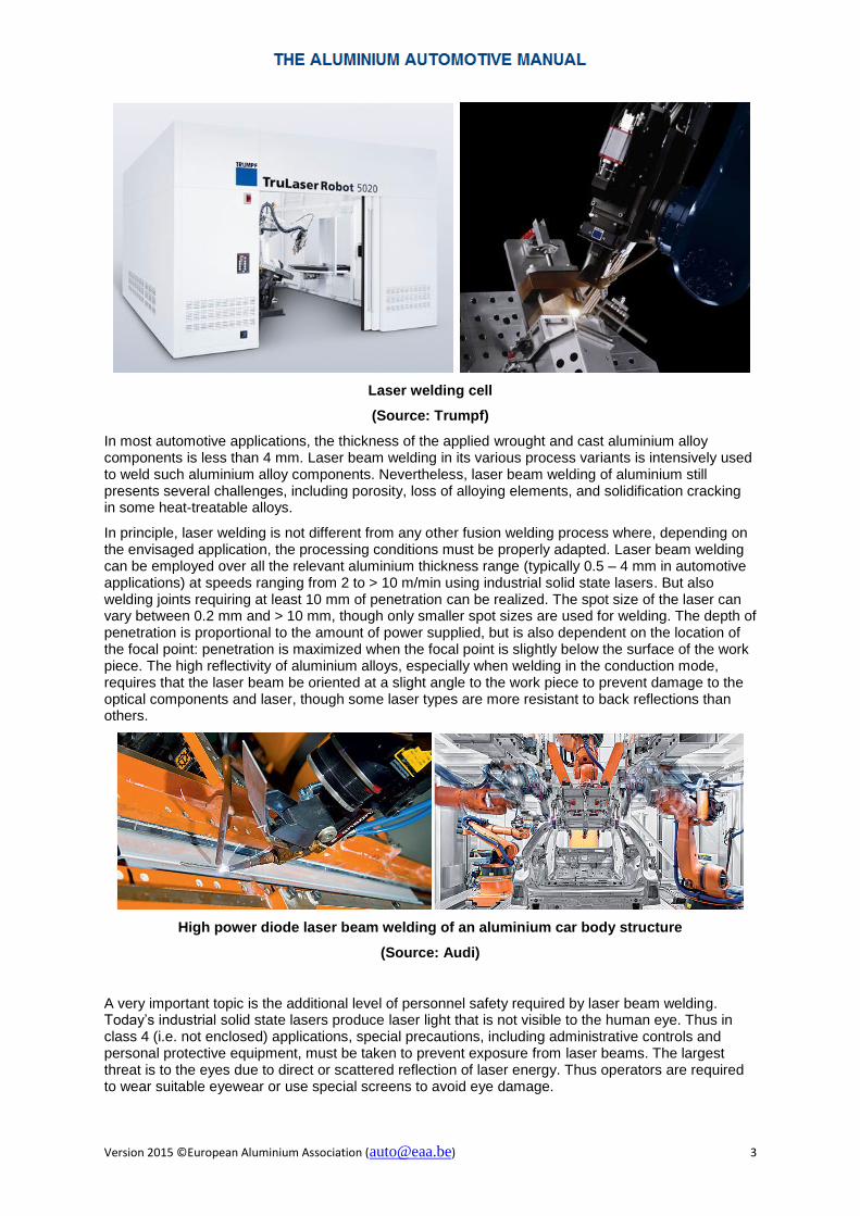
Laser welding cell
(Source: Trumpf)
In most automotive applications, the thickness of the applied wrought and cast aluminium alloy components is less than 4 mm. Laser beam welding in its various process variants is intensively used to weld such aluminium alloy components. Nevertheless, laser beam welding of aluminium still presents several challenges, including porosity, loss of alloying elements, and solidification cracking in some heat-treatable alloys.
In principle, laser welding is not different from any other fusion welding process where, depending on the envisaged application, the processing conditions must be properly adapted. Laser beam welding can be employed over all the relevant aluminium thickness range (typically 0.5 – 4 mm in automotive applications) at speeds ranging from 2 to > 10 m/min using industrial solid state lasers. But also welding joints requiring at least 10 mm of penetration can be realized. The spot size of the laser can vary between 0.2 mm and > 10 mm, though only smaller spot sizes are used for welding. The depth of penetration is proportional to the amount of power supplied, but is also dependent on the location of the focal point: penetration is maximized when the focal point is slightly below the surface of the work piece. The high reflectivity of aluminium alloys, especially when welding in the conduction mode, requires that the laser beam be oriented at a slight angle to the work piece to prevent damage to the optical components and laser, though some laser types are more resistant to back reflections than others.
High power diode laser beam welding of an aluminium car body structure
(Source: Audi)
A very important topic is the additional level of personnel safety required by laser beam welding. Today’s industrial solid state lasers produce laser light that is not visible to the human eye. Thus in class 4 (i.e. not enclosed) applications, special precautions, including administrative controls and personal protective equipment, must be taken to prevent exposure from laser beams. The largest threat is to the eyes due to direct or scattered reflection of laser energy. Thus operators are required to wear suitable eyewear or use special screens to avoid eye damage.

Version 2015 ©European Aluminium Association ([email protected]) 4
4.1.1 Laser sources
The two types of lasers commonly used for welding are solid state lasers and gas lasers. Lasers can further be grouped into several categories depending on various characteristics such as the wavelength and the quality of the light produced. A most important differentiation criterion is the mode of light emission:
− Continuous wave mode In this mode, the laser medium is pumped continuously and emits a continuous laser beam.
− Pulsing mode In the pulsed mode, the gain medium is pumped in bursts to generate short laser pulses. Power, duration and frequency of the laser pulses are important parameters for material processing.
Different kinds of joints require different operation modes of the laser device. Selection of the appropriate laser type should be made in close coordination with the
Practical metal seam welding was only feasible in the early 1970s when multi-kilowatt, continuous wave CO2 lasers were developed. In the 1980s, high power deep penetration keyhole welding of carbon steels with CO2 lasers became a regular industrial practice. However, there was only limited application of CO2 lasers for aluminium welding due to its very high reflectivity at the relatively long wavelength (10.6 μm). Practical application of flash-pumped Nd:YAG (neodymium doped-yttrium aluminium garnet) lasers, which emit a more suitable wavelength (1.06 μm), was not possible due to their low power and extremely poor efficiency at the time. In the mid-1990s, diode pumped Nd:YAG lasers were developed which offered kilowatt power and high efficiency. As a result, there was a growing interest in aluminium laser welding since the absorption of the laser beam energy in aluminium alloys at 1.06 μm is three times as much as it is at 10.6 μm. Nevertheless, the poor beam quality and high cost of diode pumped Nd:YAG lasers still hindered their acceptance in industry. In the early 2000s, with the arrival of the high power ytterbium fibre lasers, the disc and diode lasers, along with excellent beam quality and low maintenance cost, the advantages of laser welding aluminium components could be better realized.
Laser Name Lasing Medium Wavelength
[μm]
Power Beam
Quality
Electrical Efficiency
CO2 Gaseous (CO2) 10.6 Medium
/ High
High /
Medium
Low (10 %)
Fibre Solid State (Yb-doped
quartz fibre)
1.075 High High High (25 – 35 %)
YAG Solid State (Nd:YAG) 1.064 Medium Medium Low / Medium (5 – 25 %)
Disk Solid State (Yb:YAG) 1.030 High High High (25 – 35 %)
Diode Solid State 0.9 – 1.07 High Low Highest (45 %)
Common industrial laser types and characteristics
The requirement of very high laser power for aluminium welding is not only due to its high reflectivity and heat conductivity. An important parameter is also the absorption spectrum. Generally, metals have relatively high absorptions in the ultraviolet (UV) end of spectrum and low absorptions in the infrared (IR) range of the spectrum. Unlike most other metals, iron and steel have relatively high absorption factors in the IR spectrum. These materials therefore show good weldability with both solid-state and CO2 lasers. In case of aluminium, however, the decisive factor is the increase of the absorbed laser energy with decreasing wavelength. Thus for aluminium welding, solid state lasers are generally more efficient (except for welding depths > 6 – 8 mm where CO2 lasers are better).

Version 2015 ©European Aluminium Association ([email protected]) 5
The various types of solid state lasers differ somewhat in the wavelength, but more important are the differences in the intensity of the laser radiation, the quality of the laser beam and the sensitivity to back reflection. The beam quality refers to the ability to produce a beam of true Gaussian energy distribution and how tightly the beam may be focused. It depends on the laser type, the other optical components in the system and any contamination of these components. Highest beam qualities are required for cutting, while welding can tolerate slightly lower beam qualities. Welding with filler may be possible with even lower beam qualities.Thus, depending on the specific application, the most cost efficient solution must be carefully evaluated.
4.1.1.1 CO2 lasers
CO2 lasers generally use a three-component gas mixture consisting of helium, nitrogen and CO2 to generate the laser beam. High-voltage, low-current power sources supply the energy needed to excite the lasing medium. The purity of lasing gas must be extremely high in order to avoid any contamination of the laser components and thus an impaired laser performance. Moisture and hydrocarbons are particularly detrimental to the laser performance.
The wavelength of the laser beam is 10.6 μm, putting it in the far-infrared spectrum, i.e. invisible to the human eye. CO2 lasers can operate in both continuous and pulsed mode. Fibre optic cables, which are made of quartz glass and absorb this wavelength, would be destroyed. Therefore a rigid lens and a carefully aligned and maintained mirror delivery system must be used.
Owing to their reliability and durability as beam sources, CO2 lasers are well established in material processing. However, these machines require a large gas supply (except sealed CO2 lasers), draw a lot of power and produce extremely hot gas that requires cooling, which explains why their wall plug efficiency is only 10 to 12 %.
CO2 laser head (left) with mirror optic (right), the focusing mirror simultaneously deflects the laser beam by 90 degrees
(Source: Trumpf)
Version 2015 ©European Aluminium Association ([email protected]) 6
CO2 lasers typically provide a high-power, well-collimated beam of about 10 – 20 mm in diameter. While the infrared light is not well absorbed by most metals, the combination of high power (> 20 kW) and small, focussed beam diameter yields the power density necessary to initiate keyhole welding.
4.1.1.2 Solid state lasers
In solid state lasers, the light from a lamp or a series of diode lasers is focused (“pumped”) into a crystal medium, which then emits a small, well-collimated beam of laser light in the near infrared. They operate at wavelengths on the order of 1 μm, much shorter than gas lasers.
The power spectrum of solid state lasers typically ranges from 20 W to > 10 kW. Depending on the laser type, solid state lasers work in continuous operation or pulsed operation with pulse durations of milli- down to pico- or even femtoseconds, opening a vast range of possible applications. In order to deliver the laser beam to the weld area, fibre optics is usually employed.
Nd:YAG solid state lasers include a solid rod of material pumped with light from flash lamps or diodes. The basic configuration of flash lamp-pumped lasers makes them less efficient (electrical efficiency only 2 - 3 %) than diode-pumped lasers which are less complicated and have lower consumables cost (the lamps also must be replaced every few months). On the other hand, diode-pumped lasers show a higher initial purchase price. They are mostly used for conduction welding due to the combination of relatively poor beam quality and moderate power level.
Fibre lasers are conceptually like diode-pumped solid state lasers, but employ a glass fibre doped with ytterbium to generate the laser light. The laser energy is then transferred via another glass fibre to the point of use. Due to their high beam quality, they can be focused to a small spot and thus allow achieving also the power density necessary for keyhole welding. Fibre lasers produce narrow weld seams, they offer high process speeds and are increasingly used for robotic industrial welding, in particular for thin-sheet applications.
Diode lasers are a more recent development in the 1 µm wavelength range. Based on high-power diodes, the diode laser achieves its high power output through the arrangement of many electronic components in a single block. By directly coupling the diodes to an output fibre increases the wall plug efficiency while providing high flexibility. The beam quality is comparatively low; nevertheless, diode lasers are popular for use in welding metals. They produce precise and visually perfect weld seams, are energy-efficient and extremely efficient in operation. Diode lasers are best-used for conduction welding of thin metals. Because of their small size, diode laser systems can be mounted directly on robot arms and moved relatively quickly. It also makes it easier to keep them cool.
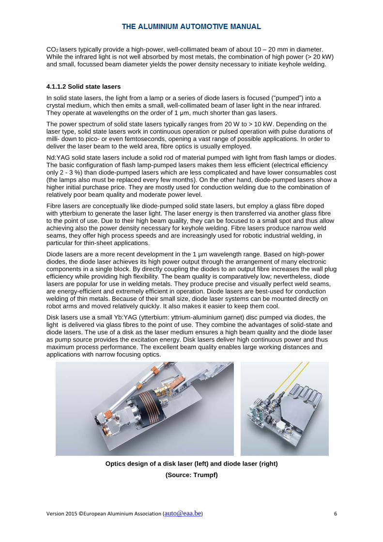
Disk lasers use a small Yb:YAG (ytterbium: yttrium-aluminium garnet) disc pumped via diodes, the light is delivered via glass fibres to the point of use. They combine the advantages of solid-state and diode lasers. The use of a disk as the laser medium ensures a high beam quality and the diode laser as pump source provides the excitation energy. Disk lasers deliver high continuous power and thus maximum process performance. The excellent beam quality enables large working distances and applications with narrow focusing optics.
Optics design of a disk laser (left) and diode laser (right)
(Source: Trumpf)

Version 2015 ©European Aluminium Association ([email protected]) 7
Solid state lasers can be placed independent of the processing location. Using flexible fibre cables, the laser beam is guided to the processing location and focused on the work piece with easy-to-integrate optics. The laser beam can traverse distances of over 100 m, without significant loss of power. However, the fibre cost, routing and handling logistic and spare part availability are considerations that limit the practical length of a fibre optic cable. Several processing stations can be supplied by a single laser.
Welding optics for solid state lasers
(Source: Trumpf)
4.1.2 Laser beam welding processes
Two main laser welding methods can be distinguished: heat conduction welding and deep penetration (keyhole) welding. Heat conduction welding is characterised by lower energy intensity on the work piece leading primarily to surface melting. When the energy intensity is significantly increased, the material is heated above its boiling point forming a keyhole which contains metal vapour. As the laser moves relative to the work piece, a deep penetrating laser weld is produced. The beneficial characteristics of keyhole welding (i.e. large penetration depth and relatively small heat affected zone) attracted more industrial applications. However, conduction welding - where vaporisation of the material is insignificant - can be a viable alternative since it is a very stable process and it is easier to obtain high quality welds free of pores and spatter.
Both continuous and pulsed lasers can be applied for welding. The short, powerful pulses of pulsed lasers are ideal for spot welding, but can also be used for seam welding. The resulting “cold” welding process is suitable in particular for components where the amount of heat introduced and the degree of deformation must be very low. High power laser sources ensure that materials with a high melting point as well as materials with a high thermal conductivity can be successfully welded.
Laser beam welding facilities can be grouped into two types. Traditionally, the laser head is moved along the weld seam, usually with a robot. Nowadays, the remote laser beam welding technique is also often used. In this method, the laser beam is moved along the seam with the help of a laser scanner, so that the robotic arm does not need to follow the seam any more. The advantages of remote laser welding are the higher speed and the higher precision of the welding process.
4.1.2.1 Heat conduction welding
Heat conduction welding is the typical mode of operation at lower power densities. In heat conduction welding, the materials to be joined are melted by absorption of the laser beam at the material surface and the solidified melt joins the mating parts along a common joint. The weld penetration depth is generally below 1 to 2 mm, there is no vaporisation of the molten material. The maximum weld depth
Version 2015 ©European Aluminium Association ([email protected]) 8
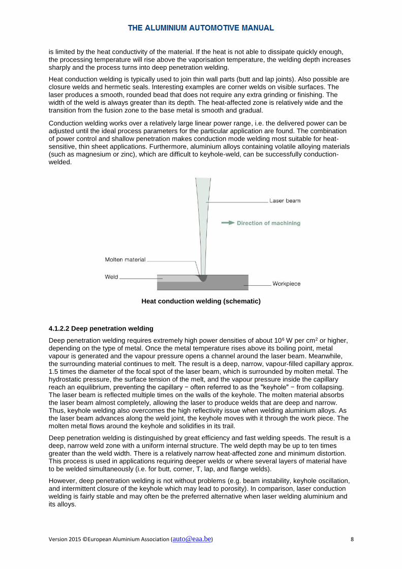
is limited by the heat conductivity of the material. If the heat is not able to dissipate quickly enough, the processing temperature will rise above the vaporisation temperature, the welding depth increases sharply and the process turns into deep penetration welding.
Heat conduction welding is typically used to join thin wall parts (butt and lap joints). Also possible are closure welds and hermetic seals. Interesting examples are corner welds on visible surfaces. The laser produces a smooth, rounded bead that does not require any extra grinding or finishing. The width of the weld is always greater than its depth. The heat-affected zone is relatively wide and the transition from the fusion zone to the base metal is smooth and gradual.
Conduction welding works over a relatively large linear power range, i.e. the delivered power can be adjusted until the ideal process parameters for the particular application are found. The combination of power control and shallow penetration makes conduction mode welding most suitable for heat-sensitive, thin sheet applications. Furthermore, aluminium alloys containing volatile alloying materials (such as magnesium or zinc), which are difficult to keyhole-weld, can be successfully conduction-welded.
Heat conduction welding (schematic)
4.1.2.2 Deep penetration welding
Deep penetration welding requires extremely high power densities of about 106 W per cm2 or higher, depending on the type of metal. Once the metal temperature rises above its boiling point, metal vapour is generated and the vapour pressure opens a channel around the laser beam. Meanwhile, the surrounding material continues to melt. The result is a deep, narrow, vapour-filled capillary approx. 1.5 times the diameter of the focal spot of the laser beam, which is surrounded by molten metal. The hydrostatic pressure, the surface tension of the melt, and the vapour pressure inside the capillary reach an equilibrium, preventing the capillary − often referred to as the "keyhole" − from collapsing. The laser beam is reflected multiple times on the walls of the keyhole. The molten material absorbs the laser beam almost completely, allowing the laser to produce welds that are deep and narrow. Thus, keyhole welding also overcomes the high reflectivity issue when welding aluminium alloys. As the laser beam advances along the weld joint, the keyhole moves with it through the work piece. The molten metal flows around the keyhole and solidifies in its trail.
Deep penetration welding is distinguished by great efficiency and fast welding speeds. The result is a deep, narrow weld zone with a uniform internal structure. The weld depth may be up to ten times greater than the weld width. There is a relatively narrow heat-affected zone and minimum distortion. This process is used in applications requiring deeper welds or where several layers of material have to be welded simultaneously (i.e. for butt, corner, T, lap, and flange welds).
However, deep penetration welding is not without problems (e.g. beam instability, keyhole oscillation, and intermittent closure of the keyhole which may lead to porosity). In comparison, laser conduction welding is fairly stable and may often be the preferred alternative when laser welding aluminium and its alloys.

Version 2015 ©European Aluminium Association ([email protected]) 9
Deep penetration welding produces a vapour-filled capillary (“keyhole”)
4.1.2.3 Twin laser welding
A possibility to increase the weld quality and the process stability is the use of two focused laser beams generated by one (“bifocal” method) or two lasers (“Twistlas” method). The result is a higher positioning and gap tolerance which is particularly useful for butt joint welding. Also the keyhole stability is improved, i.e. the time of opportunity for volatile constituents to exhaust through the keyhole is increased.
Laser welding with bifocal and Twistlas
(Source: Trumpf)
4.1.2.4 Remote laser welding
Remote laser welding uses scan mirrors for positioning the beam precisely at the desired weld location and quick decoupling in between welds. It enables the realisation of highly productive and flexible production line layouts, making laser beam welding in series production faster, more accurate, and thus more cost-effective than traditional welding processes. The essential process advantages offered by remote laser welding are single-sided component accessibility and high processing speeds up to 15 times faster in comparison to resistance spot welding.

Version 2015 ©European Aluminium Association ([email protected]) 10
Scanner welding
(Source: Trumpf)
The scanner technology offers an attractive alternative to moving the laser head or the work piece for beam positioning. Beam guidance is performed with mobile mirrors [1]. By changing the angle of the mirror, the beam can be moved in a controlled manner [4]. Using an additional lens system [2], the focus point can be moved in the Z direction. Thus three-dimensional components can be completely processed without moving either the processing head or the part. High-power disk lasers with good beam quality are used as beam sources. One or more flexible fibre optic laser cables lead the laser light from the laser unit to the processing station.
The processing field [3] determines which welds can be carried out. The processing speed and size of the focus diameter at the work piece depends on the imaging properties of the optic, the beam incidence angle, the laser beam quality and the material.
Compared to moving the work piece axes, the scanner technology enables significantly higher processing speeds with lower investment costs. The limiting factor in the scanner technology, however, is the size of the processing field. For welding applications, the spot size of the focused laser beam must be about 500 μm in order to achieve the required energy density. Historically, this has been accomplished through the use of reflective or light-transmissive optics and focal lengths have been limited to 50 to 400 mm. As a consequence, only relatively flat components of limited dimensions could be processed.
A necessary condition for the widespread introduction of the remote laser welding method into industrial practice was therefore an increase of the work envelope by increasing the focal distance. Since the focused spot size is determined by the raw beam diameter and quality, a raw laser beam of high quality and enlarged diameter is necessary. For many years, this condition limited remote welding to high-power CO2 lasers where the typical beam delivery system consists of reflective optical components. Thus the scan head had to remain stationary, limiting the working volume.
The high beam quality available with today’s solid state (diode, disk or fibre) laser systems, combined with a fibre light transport system and a beam-expanding telescope, however, enables the realisation of the required focused spot diameter even with a focal length of 1.5 to 2.25 m. Because of the long focal length of the focusing lens, small deviations of the mirror now cause long paths in the plane, and
Version 2015 ©European Aluminium Association ([email protected]) 11
thus extremely fast positioning of the focal spot at different welding positions. Due to the very fast translation movements, beam-off time is nearly eliminated, and the laser unit can produce at close to 100% of the available fabrication time.
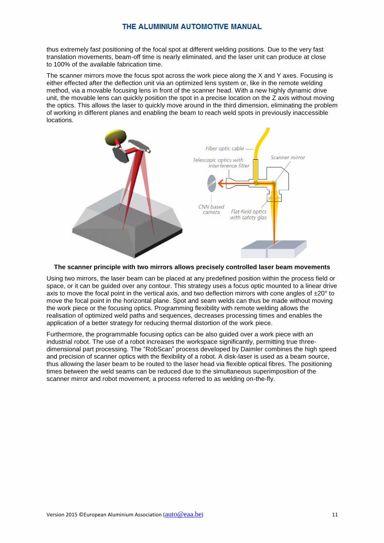
The scanner mirrors move the focus spot across the work piece along the X and Y axes. Focusing is either effected after the deflection unit via an optimized lens system or, like in the remote welding method, via a movable focusing lens in front of the scanner head. With a new highly dynamic drive unit, the movable lens can quickly position the spot in a precise location on the Z axis without moving the optics. This allows the laser to quickly move around in the third dimension, eliminating the problem of working in different planes and enabling the beam to reach weld spots in previously inaccessible locations.
The scanner principle with two mirrors allows precisely controlled laser beam movements
Using two mirrors, the laser beam can be placed at any predefined position within the process field or space, or it can be guided over any contour. This strategy uses a focus optic mounted to a linear drive axis to move the focal point in the vertical axis, and two deflection mirrors with cone angles of ±20° to move the focal point in the horizontal plane. Spot and seam welds can thus be made without moving the work piece or the focusing optics. Programming flexibility with remote welding allows the realisation of optimized weld paths and sequences, decreases processing times and enables the application of a better strategy for reducing thermal distortion of the work piece.
Furthermore, the programmable focusing optics can be also guided over a work piece with an industrial robot. The use of a robot increases the workspace significantly, permitting true three-dimensional part processing. The “RobScan” process developed by Daimler combines the high speed and precision of scanner optics with the flexibility of a robot. A disk-laser is used as a beam source, thus allowing the laser beam to be routed to the laser head via flexible optical fibres. The positioning times between the weld seams can be reduced due to the simultaneous superimposition of the scanner mirror and robot movement, a process referred to as welding on-the-fly.

Version 2015 ©European Aluminium Association ([email protected]) 12
Robotic welding with a scanning head
(Source: Trumpf)
Mounted on the end of the robot arm, the scanning head uses two electronically controlled adjustable mirrors to move the tightly focussed laser beam from one welding spot to the next at a high speed. However, the system does not stop at each welding spot to make a seam before moving on a few centimetres to the next spot. Instead, the steel robot arm continually moves along the component while the scanner head simultaneously guides the laser beam across the component.
Remote welding of door panel showing linear stitches and staple shaped welds
(Source: Daimler)
Technological developments in remote laser welding are currently going on very rapidly. Another example is the “laser stir” welding technique developed by Volkswagen. Conventionally, a gap width of 0.2 mm has been considered as the upper limit for remote laser welding. The two mirrors inside the scan head enable to rapidly focus the laser beam on the work piece with a high degree of precision. This allows manipulating the beam into a circular motion it is guided along the gap. The resulting “wobble effect” causes the laser to stir the melt pool, which increases the volume of molten material and enables to bridge gaps of up to 0.5 mm.
In addition, remote laser welding decreases production tolerances. It subjects the parts to less heat input and mechanical stress than conventional welding processes, i.e. there is less geometrical distortion of the parts. The lower number of positioning and clamping devices also contributes to a greater dimensional stability of the welded components. On the other hand, additional complexities arise when a filler metal has to be added or a shielding gas has to be integrated in order to produce a high quality joint. The large focal distance prevents direct coordination of the laser beam movement

Version 2015 ©European Aluminium Association ([email protected]) 13
and wire feeding mechanism. A solution has been found with the development of a special multi-layer aluminium sheet material (see section 4.1.5) which already incorporates the filler metal functionality.
In summary, remote laser welding is a high speed metal joining technology that involves a multi-kilowatt laser beam, an industrial robot and a laser scanning system working in combination to rapidly produce a sequence of laser welds across a work piece with minimum non-productive time. The scanner permits a reduction of the time between each weld to fractions of a second, enabling more joints to be made within a given cycle time; the robot allows the scanner to be placed where needed around the parts to be welded, reducing the number of re-orientation operations of the part. The on-going development activities ensure that this process will play an even more important role in future.
4.1.2.5 Laser welding of tubes, profiles and tailored blanks
Compared to conventional fusion welding techniques, longitudinal laser welding of tubes and profiles clearly benefits from the higher process speeds. But there are also qualitative improvements. The low heat input in laser beam welding leads amongst others to a narrow weld seam, a small heat-affected zone and little loss of alloying elements. The fine-grained microstructure of the welding seam allows subsequent forming processes with high deformation degrees, even without any heat treatment.
Endless laser welded tubes
(Source: Trumpf)
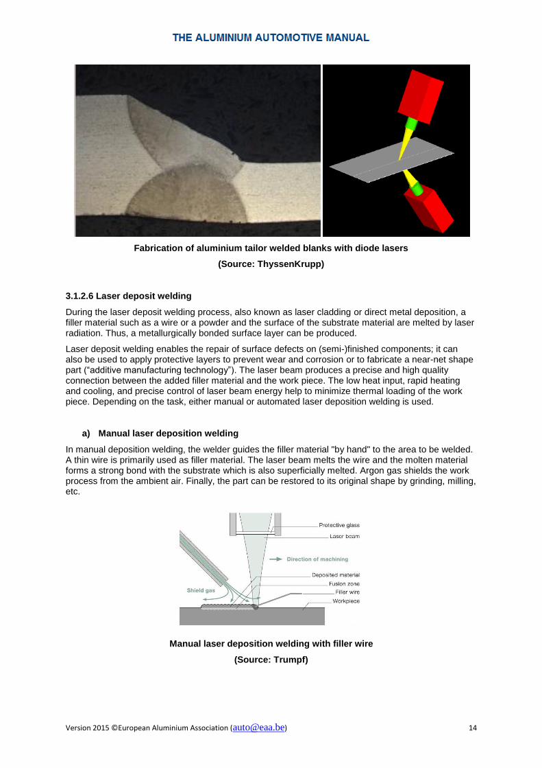
Laser welding is also a preferred method for the production of high quality aluminium tailor welded blanks. In the past, laboratory tests have been carried out using various lasers. Excellent results have been achieved in particular with two-sided simultaneous welding using two diode lasers. The use of two lasers not only increases the process speed, but also offers qualitative advantages both regarding avoidance of defects (porosity, hot cracking, etc.) and optimization of weld seam geometry
Version 2015 ©European Aluminium Association ([email protected]) 14
Fabrication of aluminium tailor welded blanks with diode lasers
(Source: ThyssenKrupp)
3.1.2.6 Laser deposit welding
During the laser deposit welding process, also known as laser cladding or direct metal deposition, a filler material such as a wire or a powder and the surface of the substrate material are melted by laser radiation. Thus, a metallurgically bonded surface layer can be produced.
Laser deposit welding enables the repair of surface defects on (semi-)finished components; it can also be used to apply protective layers to prevent wear and corrosion or to fabricate a near-net shape part (“additive manufacturing technology”). The laser beam produces a precise and high quality connection between the added filler material and the work piece. The low heat input, rapid heating and cooling, and precise control of laser beam energy help to minimize thermal loading of the work piece. Depending on the task, either manual or automated laser deposition welding is used.
a) Manual laser deposition welding
In manual deposition welding, the welder guides the filler material "by hand" to the area to be welded. A thin wire is primarily used as filler material. The laser beam melts the wire and the molten material forms a strong bond with the substrate which is also superficially melted. Argon gas shields the work process from the ambient air. Finally, the part can be restored to its original shape by grinding, milling, etc.
Manual laser deposition welding with filler wire
(Source: Trumpf)

Version 2015 ©European Aluminium Association ([email protected]) 15
b) Automated laser deposition welding
In this case, a machine guides the filler material to the area to be welded. Although the filler material can also be a wire, this process primarily uses metal powders. Metal powder is “welded” in layers to the base material without pores or cracks. After cooling, the deposited metal layer can be machined. The laser is used to generate a molten bath on the substrate surface. Powdered material is guided through the nozzle into the melt pool and, step by step, the next layer can be deposited.
Automated deposition welding, the filler material is delivered in powder form
(Source: Trumpf)
The powder used in laser cladding is injected into the system by either coaxial or lateral nozzles. Moving the substrate allows the melt pool to solidify and thus produces a track of solid metal. This is the most common technique; however some processes involve moving the laser/nozzle assembly over a stationary substrate. The injected powder is normally of metallic nature; however, ceramic particles can be also used.
The same principle can be also used to improve the surface characteristics of aluminium components by laser surface melting. In this case, the laser radiation does not penetrate the material very deeply, but changes the surface structure and/or the properties of the surface layer. The technique principally involved are laser surface melting and laser surface alloying. Pure surface re-melting can be used to modify the surface topography on a microstructural scale or to create pressure tension in the surface. With the addition of suitable powders, the composition of the surface layer can be modified allowing for example significant hardening effects (e.g. by adding iron powder). Also the wear resistance can be drastically improved for example by introducing a fine dispersion of hard ceramic particles into the surface. A wide range of unique microstructures can be produced by these techniques resulting from the extremely high cooling rates when the relatively thin laser melted surface layer is allowed to solidify in contact with the virtually unaffected substrate which acts as a large heat sink.
4.1.3 Laser welding defects
Compared to the solidification rates encountered in conventional arc welding processes (102 to 103 °C/sec), the solidification rates in laser welding are much higher (105 to 106 °C/sec). Consequently, the weld metal shows mostly a very fine grained microstructure.
Special care is necessary in process planning regarding the appropriate weld position as the low viscosity of highly fluid molten aluminium can result in dropping or sagging of the under bead. Apart from typical fusion welding defects like incomplete fusion, craters, expelled material, weld spatters and geometrical defect (misalignment, undercut, etc.), there are four types of internal weld defects in laser welding of aluminium which must be considered in more detail:
− porosity, − cracking, − inclusions and − loss of alloying elements.

Version 2015 ©European Aluminium Association ([email protected]) 16
Most gas porosity in aluminium alloys can be attributed to hydrogen. Hydrogen porosity can be a bigger problem than in conventional arc welding since the high cooling rate has an unfavourable effect which hinders diffusion of the trapped hydrogen. A possible measure to avoid excessive formation and growth of hydrogen porosity is a lower welding speed. Another way to reduce hydrogen porosity would be to increase power density and thus the solidification time, allowing the hydrogen to escape. The best option, however, is to avoid the formation of hydrogen porosity beforehand by ensuring proper quality of the starting material, suitable material storage conditions, proper surface preparation and processing conditions, etc.
But even with proper material surface preparation, laser parameters, shielding gas and filler metal, aluminium alloys are susceptible to random porosities after keyhole laser welding. These types of pores have an irregular or tubular shape and are usually located in the keyhole path, whereas hydrogen pores are more or less evenly distributed. The highest level of process-related porosity is found in the regions where an unstable keyhole is formed. Consequently the keyhole must be kept as stable as possible; this can be achieved by welding at high speeds and the addition of filler wire
Many aluminium alloys also exhibit a strong tendency for weld crack formation because of their large solidification temperature range, high coefficient of thermal expansion, and large solidification shrinkage. The restrained contraction of a weld during cooling induces tensile stresses in the joint which may cause cracking. There are two types of hot cracking: cracking that occurs in the weld fusion zone during solidification (solidification cracking), and cracking that takes place in the immediately adjoining zone due to local liquation (liquation cracking). Hot cracking sensitivity can be often avoided by adding the appropriate filler wire, thereby altering the weld chemistry away from the most crack-sensitive compositions.
External and internal weld defects that can occur in laser welding
Oxides are the main type of inclusions found in laser welded aluminium alloys. During keyhole laser welding, the inherently unstable keyhole flow may entrap shielding gas or even air because of imperfect gas shielding. Therefore, some oxide particles may be formed in the keyhole vapour. Furthermore, some surface oxide film particles may be entrapped in the weld pool.
In addition, the high power density used for laser welding may cause selective vaporisation of alloying elements with a low melting point (e.g. magnesium or zinc) because of their higher vapour pressure than aluminium. Selective vaporisation of alloying elements can take place in both keyhole and conduction laser welding. The loss of alloying elements can be minimised by controlling the beam power density, which influences the temperature of the molten metal in the welding pool. Another way to reduce the loss of alloying elements is the use of a suitable filler metal. Laser welding of aluminium alloys with the addition of a filler metal may replenish the loss of alloying elements and also prevent solidification cracking.
When the vaporised elements escape through the keyhole, they can also pull molten material along with them, leaving weld voids and spatter in their wake. The solution is to choose either a large focused spot size or to reduce the welding speed in order to allow the vapours to exhaust without causing damage.

Version 2015 ©European Aluminium Association ([email protected]) 17
4.1.4 Joint configurations
The laser welding process is characterised by high welding speeds, deep penetration effect and low heat input. This makes the laser particularly suitable for welding overlap joints. The high welding speed is advantageous for long, one-dimensional welds. On the other hand, fast and precise beam movements in remote laser welding offer the possibility to exactly position the weld spots at the required locations. Depending on the required strength of the weld and the acceptable maximum amount of heat input into the component, continuous or individual welding spots, short lines (stitches) or small circles can be made. Another advantage is of laser welding that the high accessibility, it only needs single sided access and welds can be carried out in narrow places.
Two aspects are particularly beneficial:
- the reduced flange width (i.e. reduction of component size, weight and cost), and - the increased strength and stiffness of the component as a result of the continuous joint and
weld shape optimization for loading and stresses.
Laser welded joints can be also significantly smaller and thinner than their MIG (GMA) welded counterparts. The greatest advantages in costs and productivity compared to conventional welding can be achieved when the components are intentionally designed or re-designed to take advantage of the laser joining process.
Laser welding can reduce or eliminate flanges compared with resistance spot welding (left) or enable improved (reduced weight or increased strength) designs (right)
In order to get an acceptable joint profile and weld quality, a number of processing and fit-up conditions have to be satisfied. Some examples of sheet metal joint configurations suitable for laser welding are shown below.

Version 2015 ©European Aluminium Association ([email protected]) 18
Sheet metal configurations suitable for laser welding
(Source: Trumpf)
In a specific application, the joint configuration must be selected taking into account he principle stresses acting on the joint, i.e. tension, compression or shear loads. Shear stress should be largely avoided, because most joints are very sensitive to this kind of loading.
But there are also process-specific considerations. As an example, butt joints provide higher strength, higher welding efficiency (faster or less power) and reduced material usage, but require closer positioning tolerances and better edge geometry and fit-up. The smaller weld fusion area also reduces the size of the heat affected zone and distortion of the welded assembly. On the other hand, overlap joints provide greater process window regarding positioning, but generally yield lower strength, lower welding efficiency, and increased material usage.

Version 2015 ©European Aluminium Association ([email protected]) 19
Joint Configuration Weld Fusion
Area
Positioning
Tolerance
Seam weld on butt joint
+ -
Lap weld on lap joint
- +
Seam weld on T joint
+ -
Lap weld on T joint
- +
Seam weld on flange
+ -
Lap weld on flange
- +
Characteristics of laser joint configurations
The most important requirement for reliable laser welding is a close fit-up at the joint interfaces. If the welding interfaces are too far apart, there is insufficient weld material to bridge the gap or the weld will be undercut.
Acceptable joint tolerances in laser welding
(Source: Trumpf)
However, the acceptable gap tolerance is always case specific. An improved fit-up can be achieved for example through precision shearing of the edges or the use of special clamping arrangements (such as rollers near the welding region). Furthermore, appropriate control of the laser beam can be used for better gap bridging, e.g. by increasing the spot size (if the laser source has sufficient power), by beam spitting (twin spot technique) or by weaving or wobbling the laser beam. Also possible is the addition of a filler wire or – as a last resort − the application of the laser MIG (GMA) hybrid welding method.
Another important factor is the positioning tolerance. The position of the joint under the laser must be precise enough such that the focused laser spot does not miss the joint. The tolerance of this misalignment is a function of the focused beam diameter and to a lesser extent the joint design. Seam tracking devices are therefore often used in practice.

Version 2015 ©European Aluminium Association ([email protected]) 20
Good weld fixtures using appropriate clamping devices is a prerequisite for success. When joining pre-fabricated components (e.g. formed and machined tubes or extruded profiles) or net-shaped parts (castings), even more possibilities exist as positioning aids or interlocking features can be integrated into the individual components.
4.1.5 Addition of filler wire
Laser beam welding is preferably carried out without the addition of a filler metal. However, in many cases, a filler metal must be added either for metallurgical reasons or to accommodate larger gaps. Due to the specific characteristics of laser welding, the addition of filler wire introduces a number of limitations to the process in terms of alignment, productivity (especially with remote laser welding), etc. The small laser spot and the narrow welding gap require very precise wire feeding. Thus, in practical application, sophisticated coordination between beam and wire feeding positioning mechanisms and the optical seam tracking device is necessary.
Solidification cracking is a concern when aluminium alloys are laser welded, especially in pulsed laser welding. While most non-heat treatable aluminium alloys can be welded without filler metal in the continuous wave mode, filler metal is necessary for welding heat treatable alloys. Proper filler metal selection is most important in preventing weld cracking and ensuring good mechanical characteristics of the weld (see also 2.4). In general, the filler metal alloys recommended for arc welding are also recommended for laser beam welding. Si-rich filler wires (e.g. EN AW-4043 and 4047) are typically used for laser welding of the standard automotive EN AW-6xxx alloys among each other or with EN AW-5xxx alloys (etc.). Structural EN AW-5xxx automotive alloys (with Mg < 3.5 %) can be welded without filler wire or, if appropriate, EN AW-5356 or EN AW-4043. For the selection of suitable filler wire wires for other age hardening aluminium alloy systems, please see section 2.4.1).
In practice, the wire feeding mechanism is generally attached to a robot arm together with the laser head. In specific cases, the use of ancillary equipment to preheat the wire by resistance heating (hot wire) has shown to result in increased process stability (high quality and spatter-free welding) and increased welding speeds. In the laser hot wire method, the laser beam heats the base metal. The pre-heated wire is fed in, and welded with the base metal. In the laser cold wire mode, the laser beam heats both the base metal and the filler metal, and welds them together.
Laser welding with hot (left) and cold wire (right)

Version 2015 ©European Aluminium Association ([email protected]) 21
(Source: Fronius)
As an alternative, the filler metal can also be added in powder form using the laser metal deposition approach, i.e. the filler metal powder is directly injected into the melt pool.
In remote laser welding, both mechanisms for the addition of filler metal outlined above will not work because the distance between the laser head and the weld location is too large. A solution was found with the development of the laser remote weldable car body sheet alloy Anticorodal®-200 RW (Novelis FusionTM alloy 8840). It is a patented multi-layer AlMgSi sheet product suitable for outer body application based on the Novelis Fusion™ process. The application of this multi-layer alloy enables remote laser welding without using filler material which otherwise would not be possible for EN AW-6xxx type alloys. It also enables to bridge up to 4 mm wide gaps between the components to be welded. A wide variety of weld configurations (overlap, butt, edge, edge overlap, T joint, etc.) have been successfully tested. The multi-layer alloy can be also successfully welded to conventional (monolithic) aluminium sheet and extrusion alloys as long as the multi-layer alloy Ac-200RW (8840) is on top allowing easier flow of the extra clad alloy to into the weld joint.
Multi-layer FusionTM alloy 8840 is laser weldable without filler metal
(Source: Novelis)
4.1.6 Shielding gases for laser welding
The primary function of the shielding gas during laser welding is the protection of the molten weld pool from oxidation and other environmental contaminations. For full penetration welds that require acceptable root weld profiles, the root should also be shielded with argon to prevent sagging, underfill and sharp angles. In addition, shielding gases are used to suppress plasma formation in case of CO2 lasers (which can absorb laser power), to stabilise the process and to protect the laser optics against fumes and spatter.
Nozzles for shielding gas supply

Version 2015 ©European Aluminium Association ([email protected]) 22
Coaxial, annular or lateral (side-jet) nozzles can be used for delivering the gas to the weld region. Laminar flow is a prerequisite for proper shielding gas coverage. High shielding gas velocity causes turbulence which entrains atmospheric air with the gas flow.
The choice of the shielding gas can have a significant effect on both the weld quality and the process productivity. For laser welding of aluminium, the use of argon, helium or helium-argon mixtures (up to 50% argon) is recommended; although for specialised applications, mixtures may give enhanced performance.
Originally, pure helium was used for welding since helium offers optimum protections and its application is least critical. Today the shielding gases used in laser welding tend to be more like those used in gas metal arc welding (see 2.5).
4.1.7 Characteristics of laser welding of aluminium alloys
Today, laser welding of most wrought aluminium alloys presents little problems. In particular the EN AW-5xxx and the EN AW-6xxx series alloys which are commonly used in the automotive industry can be properly laser welded. The addition of a suitable filler metal (or the application of other appropriate measures) is, however, generally necessary to safely avoid hot cracking when EN AW-6xxx alloys are joined.
The mechanical properties of laser-welded aluminium alloys depend on joint configuration, face and root bead profiles, fusion zone composition (with or without filler metal), and the amount of weld heat input. In the weld zone, depending on the alloy system(s), some of the strength achieved in the base metal by work hardening and heat treating may be lost in the weld metal. The above mentioned issues with alloying element vaporization in alloys containing Mg and Zn may also degrade the strength of the weld metal. Some reduction in cross-weld tensile strength may be also caused by cross-sectional reductions caused by welding defects (e.g. undercut or porosity).
Laser welded joints in EN AW-5xxx series alloys retain their cross-weld tensile strengths to within 80 - 100 % of the strength level of the parent material and only show a small reduction in elongation-to-failure value. The reduction in cross-weld tensile strength is due to annealing effects resulting from the heat impact. EN AW-5xxx alloys are generally welded without filler metal although a filler metal (e.g. EN AW-5356)) can be introduced to improve the strength and ductility of the joint, if desired.
For the heat-treatable EN AW-6xxx (AlMgSi) alloys, a greater loss in cross-weld tensile strength and elongation-to-failure value occurs. This drop is caused by the local dissolution of hardening precipitates and the loss of strain-hardening. The heat affected zone is also softened by over-ageing during welding. Post weld aging of the heat-treatable alloys may be used to further increase the tensile strength.
Although no special surface treatment is required when welding aluminium, care has to be taken to avoid excessive porosity. The predominant cause for porosity is the evolution of hydrogen gas during weld metal solidification. This hydrogen can originate from lubricants, moisture in the atmosphere and surface oxides or the presence of hydrogen in the parent material. Good quality welds can be achieved for most alloys by cleaning the surfaces prior to welding and adequate inert gas shielding of the weld pool area.
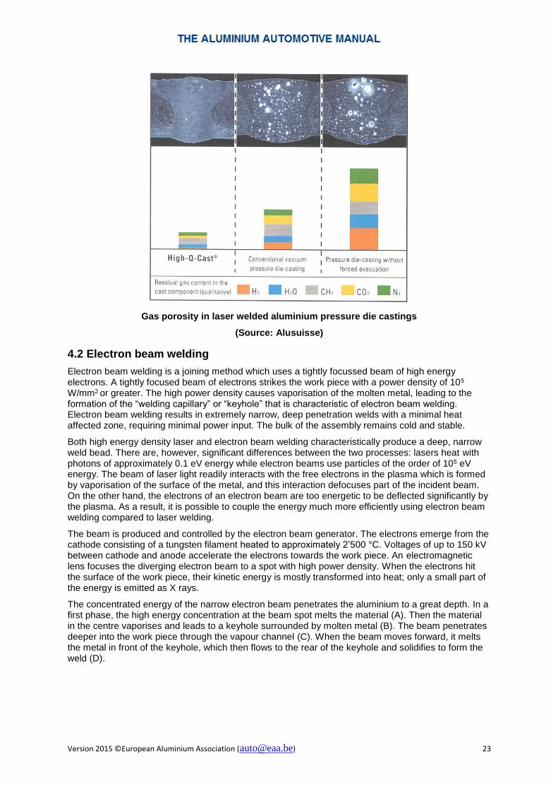
Hydrogen content may, however, present problems when aluminium castings are laser welded. Whereas for example the MIG (GMA) arc welding method will still produce an adequate weld joint quality in conventional high pressure die castings, the faster laser welding process may lead to an irregular distribution of relatively large gas pores (i.e. an inacceptable joint quality). Only castings produced with high quality vacuum pressure die casting techniques are properly weldable using the laser welding process.
Version 2015 ©European Aluminium Association ([email protected]) 23
Gas porosity in laser welded aluminium pressure die castings
(Source: Alusuisse)
4.2 Electron beam welding
Electron beam welding is a joining method which uses a tightly focussed beam of high energy electrons. A tightly focused beam of electrons strikes the work piece with a power density of 105 W/mm2 or greater. The high power density causes vaporisation of the molten metal, leading to the formation of the “welding capillary” or “keyhole” that is characteristic of electron beam welding. Electron beam welding results in extremely narrow, deep penetration welds with a minimal heat affected zone, requiring minimal power input. The bulk of the assembly remains cold and stable.
Both high energy density laser and electron beam welding characteristically produce a deep, narrow weld bead. There are, however, significant differences between the two processes: lasers heat with photons of approximately 0.1 eV energy while electron beams use particles of the order of 105 eV energy. The beam of laser light readily interacts with the free electrons in the plasma which is formed by vaporisation of the surface of the metal, and this interaction defocuses part of the incident beam. On the other hand, the electrons of an electron beam are too energetic to be deflected significantly by the plasma. As a result, it is possible to couple the energy much more efficiently using electron beam welding compared to laser welding.
The beam is produced and controlled by the electron beam generator. The electrons emerge from the cathode consisting of a tungsten filament heated to approximately 2’500 °C. Voltages of up to 150 kV between cathode and anode accelerate the electrons towards the work piece. An electromagnetic lens focuses the diverging electron beam to a spot with high power density. When the electrons hit the surface of the work piece, their kinetic energy is mostly transformed into heat; only a small part of the energy is emitted as X rays.
The concentrated energy of the narrow electron beam penetrates the aluminium to a great depth. In a first phase, the high energy concentration at the beam spot melts the material (A). Then the material in the centre vaporises and leads to a keyhole surrounded by molten metal (B). The beam penetrates deeper into the work piece through the vapour channel (C). When the beam moves forward, it melts the metal in front of the keyhole, which then flows to the rear of the keyhole and solidifies to form the weld (D).

Version 2015 ©European Aluminium Association ([email protected]) 24
Electron beam welding process
(Source: Steigerwald Strahltechnik)
The energy absorption on the work piece is nearly independent of the incident angle, the type of material and surface state. Consequently in electron beam welding, the electrical wall-plug efficiency is high (> 50 %, including all auxiliaries).
Various types of weld are distinguished depending on the basic geometric shape of the components; the welds can be made continuous, discontinuous or as a spot weld.
Vacuum (left) and non-vacuum (right) electron beam welding technology
(Source: Steigerwald Strahltechnik)

Version 2015 ©European Aluminium Association ([email protected]) 25
4.2.1 Vacuum electron beam welding
Electron beam welding is traditionally performed with the component to be welded contained entirely within a vacuum chamber. The generator is mounted to the processing chamber. With a conventional beam generator, a vacuum better than 10 -4 mbar must be achieved in the electron gun vacuum envelope. In industrial systems, the processing chamber pressure typically ranges from 10 -2 mbar to 10 -4 mbar. Whilst in many applications a vacuum welding environment is attractive, for large parts and where high productivity is required, the need for an evacuated chamber can drastically hinder efficient work. The limiting factor is the pump cycle time which may be reduced by twin chamber machines.
Electron beam welds are usually either fully penetrating or partially penetrating. Electron beam welding creates high integrity joints with low heat input. The narrow melt and heat affected zones minimises distortion to the component as whole. Depth-width-ratios of 50:1 and welding depths up to 300 mm are possible. Deep weld penetration can be achieved in a single pass with a high welding speed (>>10 m/min). Normally the components are welded without filler materials, but are added when necessary. Welding in vacuum ensures in a clean and reproducible environment and protects the molten metal. The mechanised (or automated) operation guarantees reliability and reproducibility.
Electron beam welding under vacuum causes a low divergence of the electron beam. The power density with a beam power of 100 kW or more and a spot diameter between 0.1 and 1 mm is extremely high. The beam is moved over the work piece either by electromagnetic deflection or mechanical motion or both, enabling rapid changes of weld direction combined with high welding speeds. It is also possible to oscillate the beam by modulation of the frequencies of the free programmable deflector coils in order to improve out-gassing of the weld and gap bridging. It is important to maintain the cavity long enough for optimum degassing to keep porosity to a minimum.
The preferred joint geometries are lap joints and simple butt joints. Also used are weld pool supported joints, joints with positioning guides and special weld geometries for penetration improvement.
4.2.2 Non-vacuum electron beam welding
Non-vacuum electron beam welding employs essentially the same equipment as vacuum electron beam welding except that the working chamber is replaced by an orifice system. The electron beam emerges from the gun column via a series of differentially pumped vacuum stages which are separated by small diameter orifices. Thus the need for evacuation time is eliminated, as the orifice system and the generator column are permanently kept under vacuum. The electron beam is guided to the atmosphere (1’000 mbar) from the high vacuum (10-4 mbar) in the electron beam generator over a soft vacuum (10-2 mbar) and rough vacuum (< 1 mbar).
The other difference is that in vacuum electron beam welding, the working distance can be varied over a wide range (up to 2000 mm) by changing the lens current. In non-vacuum electron beam welding, the working distance is fixed. The electron beam is focused on the outer nozzle of the orifice system which has a diameter between 1 mm and 2 mm. This small nozzle makes sure that only a

Version 2015 ©European Aluminium Association ([email protected]) 26
small amount of vaporized material can reach the rough vacuum range and the beam generator. Additionally a cross-jet of the applied processing gas, crosswise to the beam direction, seals the orifice. Thus a steady welding operation is guaranteed. Differences in the working distance are equalized by moving the electron beam generator.
After leaving the nozzle, a diffuse and diverging electron beam is formed due to the interaction of the electrons with the gas molecules in the surrounding air. The power distribution of the electron beam allows keyhole welding within a distance of up to 25 mm working distance. A minimum working distance (> 5 mm) must be kept to prevent a thermal distortion of the orifice system.
In non-vacuum electron beam welding, the use of a shielding gas (He, Ar) to protect the weld pool is generally necessary. In addition, a working gas protects the nozzle and beam generator against pollution. Helium is the preferred working/shielding gas. With its small atomic diameter, helium minimises the expansion of the electron beam. The gas quantity and the working distance are important parameters apart from the beam parameters (beam current and acceleration voltage). They all influence welding velocity, welding depth and joint quality.
With non-vacuum electron beam welding, deep penetration welding with depth-width-ratios of 5:1 can be reached. Non-vacuum electron beam welding allows single pass welding of thick section at atmospheric pressure with weld characteristics similar to those produced by in-vacuum welding, i.e. low distortion and high weld quality. The diverging and high-energy electron beam permits a good gap bridging without using filler material and is insensitive to working distance variations and pollution. Gaps between 0.1 up to 1 mm can be tolerated depending on the joint design, material thickness and welding speed. If necessary, a filler material can be used. However, in this case, the welding velocity is reduced
Welding depth as a function of welding speed in non-vacuum electron beam welding
(Source: Steigerwald Strahltechnik)
The classical application for non-vacuum electron beam welding is welding of thin metal sheets (< 5 mm). Flange and overlap joints are ideal joints for non-vacuum electron beam welding. Due to the presence of large material quantities, only coarse joint preparation is required and relative large gaps can be tolerated. The “tailored blank“ joint allows gaps of a few tenth of a millimetre. In case of a butt weld, gaps with < 0.1 mm are only tolerated without filler metal.

Version 2015 ©European Aluminium Association ([email protected]) 27
Joint geometries for non-vacuum electron beam welding
(Source: Steigerwald Strahltechnik)
Most important in electron beam welding is proper protection from the emitted X rays. Whereas in vacuum electron beam welding, the vacuum chamber provides the necessary protection, the working area of a non-vacuum electron beam welding machine must be shielded by properly adopted lead walls.
4.2.3 Electron beam welding of aluminium alloys
Electron beam welding can be used to join aluminium alloys in a similar manner as laser beam welding. There are no electron beam-specific issues or problems. It also allows joining different types of materials, e.g. joining aluminium and steel. As the energy input can be precisely controlled, durable weld-solder joints can be made (in this case, the steel partner remains solid and the aluminium is fused to it).
Version 2015 ©European Aluminium Association ([email protected]) 28
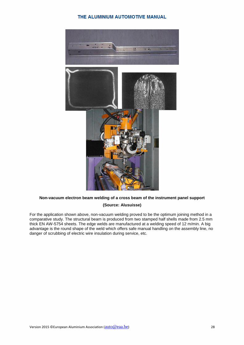
Non-vacuum electron beam welding of a cross beam of the instrument panel support
(Source: Alusuisse) For the application shown above, non-vacuum welding proved to be the optimum joining method in a comparative study. The structural beam is produced from two stamped half shells made from 2.5 mm thick EN AW-5754 sheets. The edge welds are manufactured at a welding speed of 12 m/min. A big advantage is the round shape of the weld which offers safe manual handling on the assembly line, no danger of scrubbing of electric wire insulation during service, etc.

Related Documents