V1.1 – EA001A Calibration Guide – updated 27/03/2015 Transmille Ltd Unit 4 Select Business Centre Lodge Road Staplehurst Kent TN12 0QW United Kingdom www.transmille.com EA001A Calibration Guide Table of Contents Equipment Required ......................................................................................................... 2 Calibration Procedure ...................................................................................................... 3 Cold Junction – Source Function. ............................................................................................ 3 Cold Junction – Measure Function ......................................................................................... 4 Thermocouple simulation output Function ....................................................................... 5 Thermocouple measurement input Function ................................................................... 7 Appendix 1: EA001A Extended Specifications.......................................................... 9

Welcome message from author
This document is posted to help you gain knowledge. Please leave a comment to let me know what you think about it! Share it to your friends and learn new things together.
Transcript

1
V1.1 – EA001A Calibration Guide – updated 27/03/2015
Transmille Ltd Unit 4 Select Business Centre
Lodge Road Staplehurst
Kent TN12 0QW
United Kingdom www.transmille.com
EA001A Calibration Guide
Table of Contents
Equipment Required ......................................................................................................... 2
Calibration Procedure ...................................................................................................... 3 Cold Junction – Source Function. ............................................................................................ 3 Cold Junction – Measure Function ......................................................................................... 4 Thermocouple simulation output Function ....................................................................... 5 Thermocouple measurement input Function ................................................................... 7
Appendix 1: EA001A Extended Specifications .......................................................... 9
2
V1.1 – EA001A Calibration Guide – updated 27/03/2015
Transmille Ltd Unit 4 Select Business Centre
Lodge Road Staplehurst
Kent TN12 0QW
United Kingdom www.transmille.com
EA001A Calibration Guide
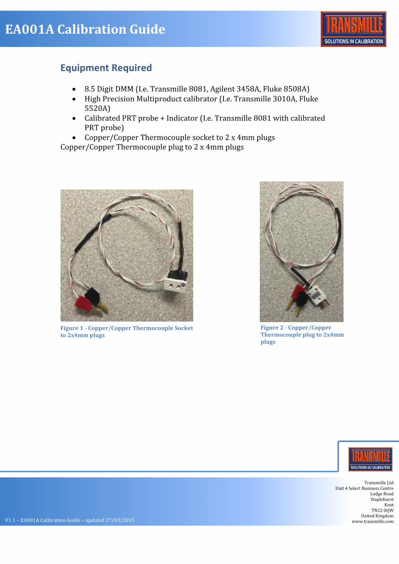
Equipment Required
8.5 Digit DMM (I.e. Transmille 8081, Agilent 3458A, Fluke 8508A) High Precision Multiproduct calibrator (I.e. Transmille 3010A, Fluke
5520A) Calibrated PRT probe + Indicator (I.e. Transmille 8081 with calibrated
PRT probe) Copper/Copper Thermocouple socket to 2 x 4mm plugs
Copper/Copper Thermocouple plug to 2 x 4mm plugs
Figure 1 - Copper/Copper Thermocouple Socket to 2x4mm plugs
Figure 2 - Copper/Copper Thermocouple plug to 2x4mm plugs
3
V1.1 – EA001A Calibration Guide – updated 27/03/2015
Transmille Ltd Unit 4 Select Business Centre
Lodge Road Staplehurst
Kent TN12 0QW
United Kingdom www.transmille.com
EA001A Calibration Guide
Calibration Procedure
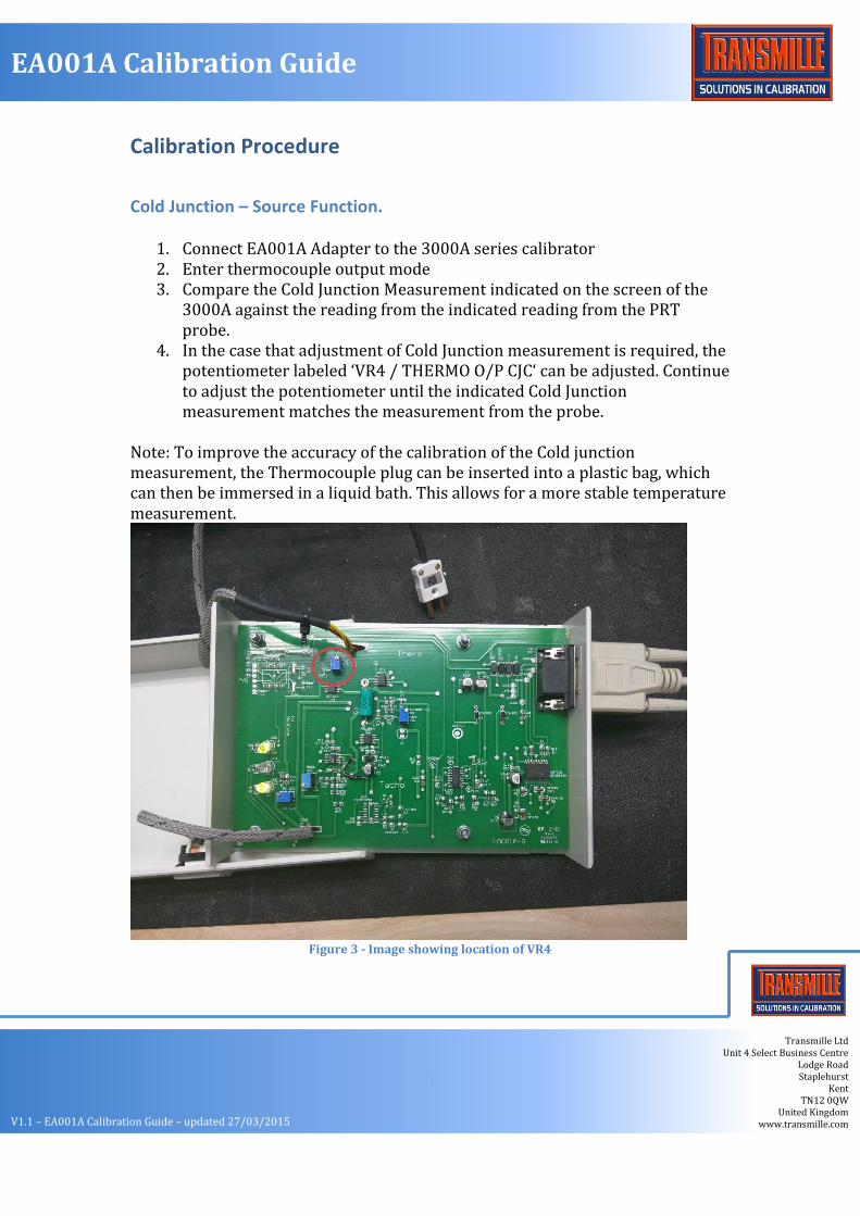
Cold Junction – Source Function.
1. Connect EA001A Adapter to the 3000A series calibrator 2. Enter thermocouple output mode 3. Compare the Cold Junction Measurement indicated on the screen of the
3000A against the reading from the indicated reading from the PRT probe.
4. In the case that adjustment of Cold Junction measurement is required, the potentiometer labeled ‘VR4 / THERMO O/P CJC‘ can be adjusted. Continue to adjust the potentiometer until the indicated Cold Junction measurement matches the measurement from the probe.
Note: To improve the accuracy of the calibration of the Cold junction measurement, the Thermocouple plug can be inserted into a plastic bag, which can then be immersed in a liquid bath. This allows for a more stable temperature measurement.
Figure 3 - Image showing location of VR4
4
V1.1 – EA001A Calibration Guide – updated 27/03/2015
Transmille Ltd Unit 4 Select Business Centre
Lodge Road Staplehurst
Kent TN12 0QW
United Kingdom www.transmille.com
EA001A Calibration Guide
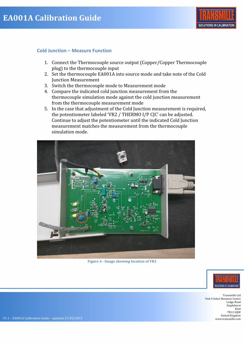
Cold Junction – Measure Function
1. Connect the Thermocouple source output (Copper/Copper Thermocouple plug) to the thermocouple input
2. Set the thermocouple EA001A into source mode and take note of the Cold Junction Measurement
3. Switch the thermocouple mode to Measurement mode 4. Compare the indicated cold junction measurement from the
thermocouple simulation mode against the cold junction measurement from the thermocouple measurement mode
5. In the case that adjustment of the Cold Junction measurement is required, the potentiometer labeled ‘VR2 / THERMO I/P CJC’ can be adjusted. Continue to adjust the potentiometer until the indicated Cold Junction measurement matches the measurement from the thermocouple simulation mode.
Figure 4 - Image showing location of VR2

5
V1.1 – EA001A Calibration Guide – updated 27/03/2015
Transmille Ltd Unit 4 Select Business Centre
Lodge Road Staplehurst
Kent TN12 0QW
United Kingdom www.transmille.com
EA001A Calibration Guide
Thermocouple simulation output Function
1. Connect the thermocouple output plug into the Copper/Copper Thermocouple socket
2. Connect the 2 x 4mm plugs to the Voltage terminals of the DMM. 3. With the EA001A thermocouple disconnected from the calibrator,
perform a Null. This removes any voltage offsets in the leads and connections. As the thermocouple outputs are accurate in terms of µV it is essential to correctly null the system for measurements.
4. Connect the EA001A to the calibrator 5. Set the cold junction compensation to Manual, with a setting of 0’C 6. Set the required thermocouple type and value and press output on 7. Proceed through the test points in the Calibration worksheet in the
Appendix 8. If the thermocouple is found to require adjustment, set the calibrator to a
setting of 5V DC 9. The setting of 5V will equate to an output of 50mV DC from the EA001A 10. Adjust potentiometer ‘VR3 / THERMO O/P ADJ‘ for a setting of 50mV
output as measured by the DMM 11. Proceed to re-verify the EA001A output
Figure 5 - Image showing connection described in Step 1
6
V1.1 – EA001A Calibration Guide – updated 27/03/2015
Transmille Ltd Unit 4 Select Business Centre
Lodge Road Staplehurst
Kent TN12 0QW
United Kingdom www.transmille.com
EA001A Calibration Guide
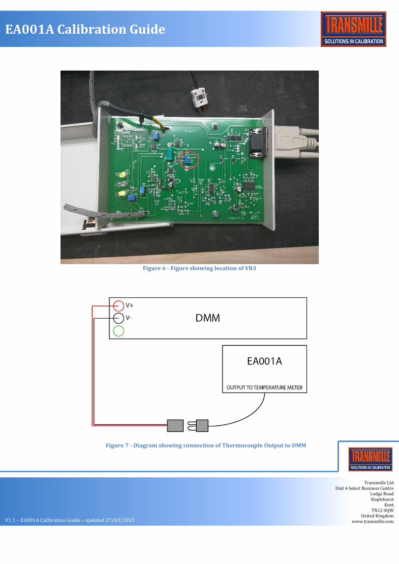
Figure 6 - Figure showing location of VR3
Figure 7 - Diagram showing connection of Thermocouple Output to DMM
7
V1.1 – EA001A Calibration Guide – updated 27/03/2015
Transmille Ltd Unit 4 Select Business Centre
Lodge Road Staplehurst
Kent TN12 0QW
United Kingdom www.transmille.com
EA001A Calibration Guide
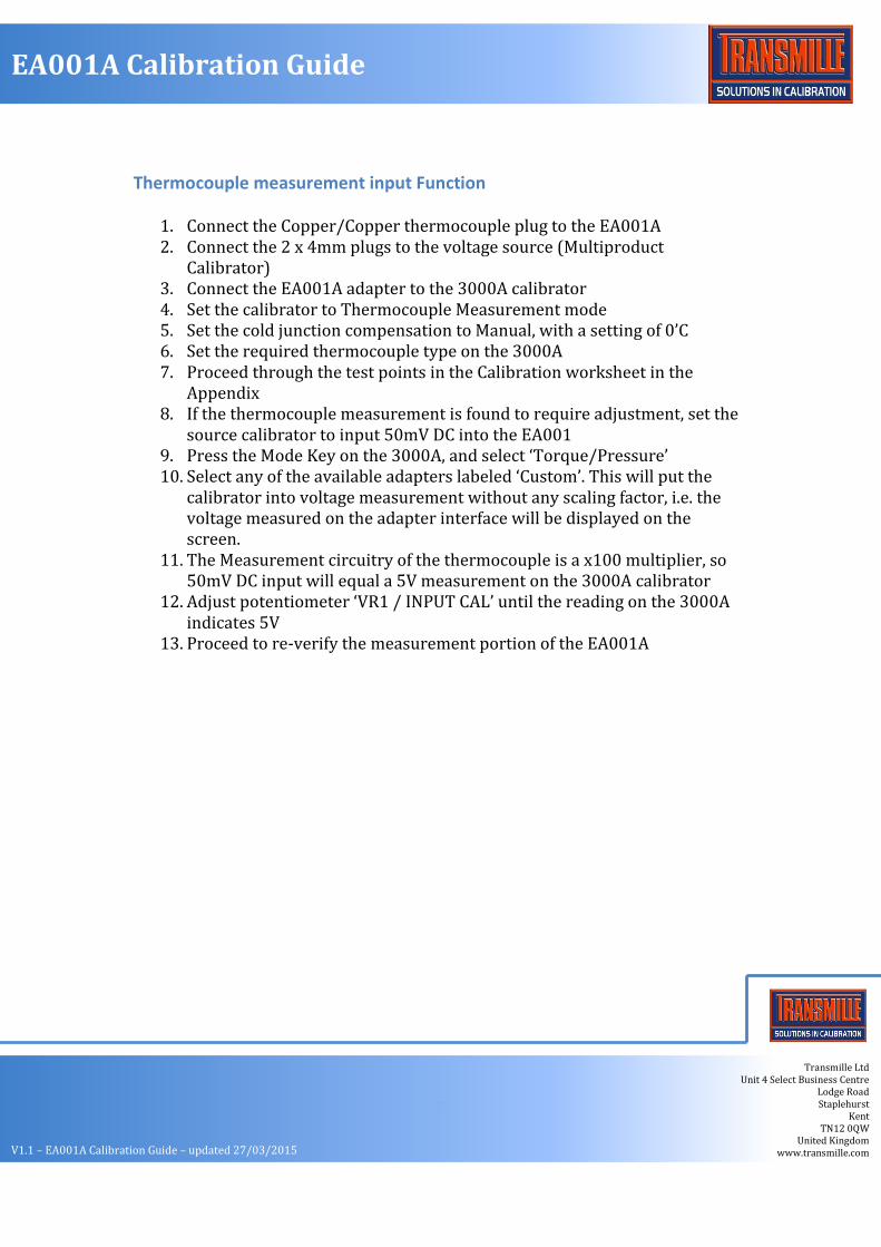
Thermocouple measurement input Function
1. Connect the Copper/Copper thermocouple plug to the EA001A 2. Connect the 2 x 4mm plugs to the voltage source (Multiproduct
Calibrator) 3. Connect the EA001A adapter to the 3000A calibrator 4. Set the calibrator to Thermocouple Measurement mode 5. Set the cold junction compensation to Manual, with a setting of 0’C 6. Set the required thermocouple type on the 3000A 7. Proceed through the test points in the Calibration worksheet in the
Appendix 8. If the thermocouple measurement is found to require adjustment, set the
source calibrator to input 50mV DC into the EA001 9. Press the Mode Key on the 3000A, and select ‘Torque/Pressure’ 10. Select any of the available adapters labeled ‘Custom’. This will put the
calibrator into voltage measurement without any scaling factor, i.e. the voltage measured on the adapter interface will be displayed on the screen.
11. The Measurement circuitry of the thermocouple is a x100 multiplier, so 50mV DC input will equal a 5V measurement on the 3000A calibrator
12. Adjust potentiometer ‘VR1 / INPUT CAL’ until the reading on the 3000A indicates 5V
13. Proceed to re-verify the measurement portion of the EA001A

8
V1.1 – EA001A Calibration Guide – updated 27/03/2015
Transmille Ltd Unit 4 Select Business Centre
Lodge Road Staplehurst
Kent TN12 0QW
United Kingdom www.transmille.com
EA001A Calibration Guide
Figure 8 - Image showing location of VR1
Figure 9 - Diagram showing connection of EA001A Thermocouple input to Multiproduct Calibrator
9
V1.1 – EA001A Calibration Guide – updated 27/03/2015
Transmille Ltd Unit 4 Select Business Centre
Lodge Road Staplehurst
Kent TN12 0QW
United Kingdom www.transmille.com
EA001A Calibration Guide
Appendix 1: EA001A Extended Specifications Extended specifications are correct at the time of printing, for the most up to date specifications please download from www.transmille.com
10
V1.1 – EA001A Calibration Guide – updated 27/03/2015
Transmille Ltd Unit 4 Select Business Centre
Lodge Road Staplehurst
Kent TN12 0QW
United Kingdom www.transmille.com
EA001A Calibration Guide
EA001A Extended Specifications TRANSMILLE LTD
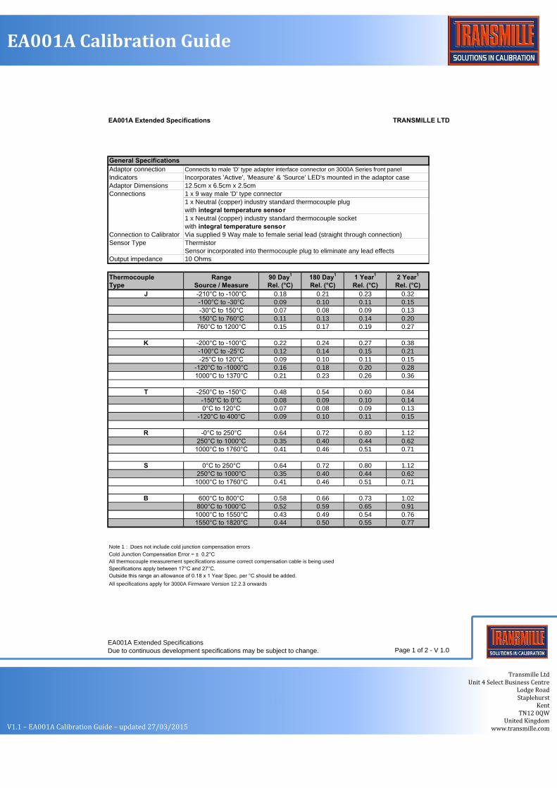
General Specifications
Adaptor connection Connects to male 'D' type adapter interface connector on 3000A Series front panel
Indicators Incorporates 'Active', 'Measure' & 'Source' LED's mounted in the adaptor case
Adaptor Dimensions 12.5cm x 6.5cm x 2.5cm
Connections 1 x 9 way male 'D' type connector
1 x Neutral (copper) industry standard thermocouple plug
with integral temperature sensor
1 x Neutral (copper) industry standard thermocouple socket
with integral temperature sensor
Connection to Calibrator Via supplied 9 Way male to female serial lead (straight through connection)
Sensor Type Thermistor
Sensor incorporated into thermocouple plug to eliminate any lead effects
Output impedance 10 Ohms
Thermocouple Range 90 Day1
180 Day1
1 Year1
2 Year1
Type Source / Measure Rel. (°C) Rel. (°C) Rel. (°C) Rel. (°C)
J -210°C to -100°C 0.18 0.21 0.23 0.32
-100°C to -30°C 0.09 0.10 0.11 0.15
-30°C to 150°C 0.07 0.08 0.09 0.13
150°C to 760°C 0.11 0.13 0.14 0.20
760°C to 1200°C 0.15 0.17 0.19 0.27
K -200°C to -100°C 0.22 0.24 0.27 0.38
-100°C to -25°C 0.12 0.14 0.15 0.21
-25°C to 120°C 0.09 0.10 0.11 0.15
-120°C to -1000°C 0.16 0.18 0.20 0.28
1000°C to 1370°C 0.21 0.23 0.26 0.36
T -250°C to -150°C 0.48 0.54 0.60 0.84
-150°C to 0°C 0.08 0.09 0.10 0.14
0°C to 120°C 0.07 0.08 0.09 0.13
-120°C to 400°C 0.09 0.10 0.11 0.15
R -0°C to 250°C 0.64 0.72 0.80 1.12
250°C to 1000°C 0.35 0.40 0.44 0.62
1000°C to 1760°C 0.41 0.46 0.51 0.71
S 0°C to 250°C 0.64 0.72 0.80 1.12
250°C to 1000°C 0.35 0.40 0.44 0.62
1000°C to 1760°C 0.41 0.46 0.51 0.71
B 600°C to 800°C 0.58 0.66 0.73 1.02
800°C to 1000°C 0.52 0.59 0.65 0.91
1000°C to 1550°C 0.43 0.49 0.54 0.76
1550°C to 1820°C 0.44 0.50 0.55 0.77
Note 1 : Does not include cold junction compensation errors
Cold Junction Compensation Error = ± 0.2°C
All thermocouple measurement specifications assume correct compensation cable is being used
Specifications apply between 17°C and 27°C.
Outside this range an allowance of 0.18 x 1 Year Spec. per °C should be added.
All specifications apply for 3000A Firmware Version 12.2.3 onwards
EA001A Extended Specifications
Due to continuous development specifications may be subject to change. Page 1 of 2 - V 1.0
11
V1.1 – EA001A Calibration Guide – updated 27/03/2015
Transmille Ltd Unit 4 Select Business Centre
Lodge Road Staplehurst
Kent TN12 0QW
United Kingdom www.transmille.com
EA001A Calibration Guide
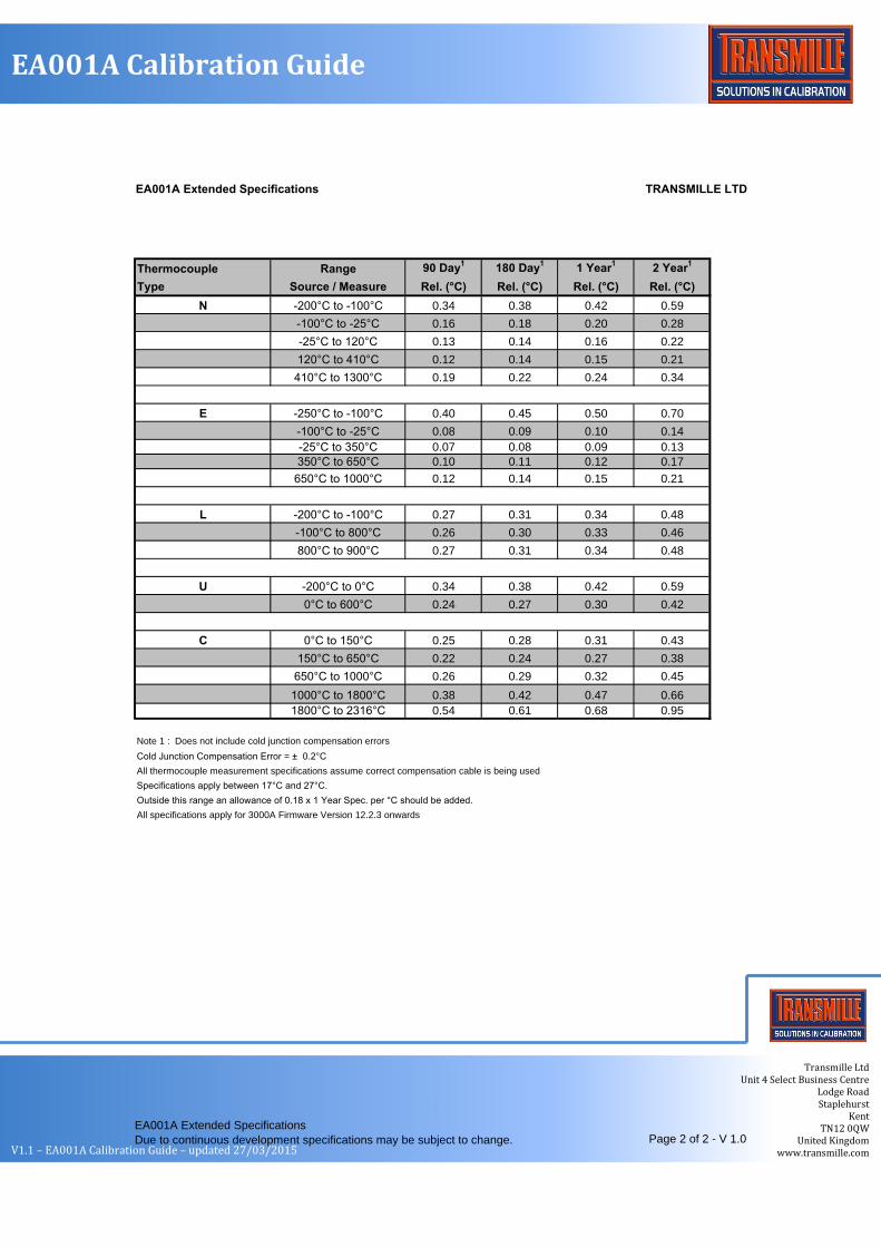
EA001A Extended Specifications TRANSMILLE LTD
Thermocouple Range 90 Day1
180 Day1
1 Year1
2 Year1
Type Source / Measure Rel. (°C) Rel. (°C) Rel. (°C) Rel. (°C)
N -200°C to -100°C 0.34 0.38 0.42 0.59
-100°C to -25°C 0.16 0.18 0.20 0.28
-25°C to 120°C 0.13 0.14 0.16 0.22
120°C to 410°C 0.12 0.14 0.15 0.21
410°C to 1300°C 0.19 0.22 0.24 0.34
E -250°C to -100°C 0.40 0.45 0.50 0.70
-100°C to -25°C 0.08 0.09 0.10 0.14
-25°C to 350°C 0.07 0.08 0.09 0.13
350°C to 650°C 0.10 0.11 0.12 0.17
650°C to 1000°C 0.12 0.14 0.15 0.21
L -200°C to -100°C 0.27 0.31 0.34 0.48
-100°C to 800°C 0.26 0.30 0.33 0.46
800°C to 900°C 0.27 0.31 0.34 0.48
U -200°C to 0°C 0.34 0.38 0.42 0.59
0°C to 600°C 0.24 0.27 0.30 0.42
C 0°C to 150°C 0.25 0.28 0.31 0.43
150°C to 650°C 0.22 0.24 0.27 0.38
650°C to 1000°C 0.26 0.29 0.32 0.45
1000°C to 1800°C 0.38 0.42 0.47 0.66
1800°C to 2316°C 0.54 0.61 0.68 0.95
Note 1 : Does not include cold junction compensation errors
Cold Junction Compensation Error = ± 0.2°C
All thermocouple measurement specifications assume correct compensation cable is being used
Specifications apply between 17°C and 27°C.
Outside this range an allowance of 0.18 x 1 Year Spec. per °C should be added.
All specifications apply for 3000A Firmware Version 12.2.3 onwards
EA001A Extended Specifications
Due to continuous development specifications may be subject to change. Page 2 of 2 - V 1.0
Related Documents