Z206855-0C Page 1 of 31 ©2015 Veris Industries USA 800.354.8556 or +1.503.598.4564 / [email protected] 0815 Alta Labs, Enercept, Enspector, Hawkeye, Trustat, Aerospond, Veris, and the Veris ‘V’ logo are trademarks or registered trademarks of Veris Industries, L.L.C. in the USA and/or other countries. Other companies’ trademarks are hereby acknowledged to belong to their respective owners. Installation Guide Power Monitoring TM Product Identification Product Overview The E31E Series panelboard monitoring system is designed to measure the current, voltage, and energy consumption of up to 92 circuits (84 branch circuits, 2 3-phase mains, 2 neutrals), enabling users to monitor two panelboards or an entire data center PDU with a single product. The E31E consists of a data acquisition module, up to four current sensor adapter boards, and up to 84 split-core branch current sensors (50A, 100A, or 200A), with eight auxiliary inputs. Each conductor passes through the appropriate branch current sensor before terminating at the breaker. Each sensor transmits the current data to the data acquisition board. The E31E measures both current and power for the mains and branch circuits. The E31E can easily accommodate different panel configurations, including any combination of multi-phase breaker positions, voltage phase mapping, and breaker sizes. To configure the E31E for operation, download the NetConfig configuration software tool and the E3x Commissioning Guide from the Veris website at www.veris.com /modbus_downloads. Data is transmitted via Ethernet with Modbus TCP, BACnet IP or SNMP protocol, or via RS-485 with Modbus RTU or BACnet MS/TP protocols. Some protocols can be used simultaneously, and the Ethernet protocols all support access by multiple masters. Each data acquisition board requires two Modbus addresses, one for each set of 42 current sensors, and four auxiliary inputs. When a circuit exceeds the user-defined thresholds, the E31E activates the alarm indicators. The communication interfaces and protocols require configuration at the time of installation. E31E Series Branch Circuit Power Meter with Ethernet Communication E31E # of CTs 002 = 2 adapter boards, no CTs, no cables 004 = 4 adapter boards, no CTs, no cables 42 = 2 adapter boards, 42 50A CTs, 2 4 ft. round ribbon cables 84 = 4 adapter boards, 84 50A CTs, 4 4 ft. round ribbon cables * *The CE mark indicates RoHS2 compliance. Please refer to the CE Declaration of Conformity for additional details.

Welcome message from author
This document is posted to help you gain knowledge. Please leave a comment to let me know what you think about it! Share it to your friends and learn new things together.
Transcript

Z206855-0C Page 1 of 31 ©2015 Veris Industries USA 800.354.8556 or +1.503.598.4564 / [email protected] 0815 Alta Labs, Enercept, Enspector, Hawkeye, Trustat, Aerospond, Veris, and the Veris ‘V’ logo are trademarks or registered trademarks of Veris Industries, L.L.C. in the USA and/or other countries.
Other companies’ trademarks are hereby acknowledged to belong to their respective owners.
Installation GuidePower Monitoring TM
Product Identification
Product OverviewThe E31E Series panelboard monitoring system is designed to measure the current, voltage, and energy consumption of up to 92 circuits (84 branch circuits, 2 3-phase mains, 2 neutrals), enabling users to monitor two panelboards or an entire data center PDU with a single product.
The E31E consists of a data acquisition module, up to four current sensor adapter boards, and up to 84 split-core branch current sensors (50A, 100A, or 200A), with eight auxiliary inputs. Each conductor passes through the appropriate branch current sensor before terminating at the breaker. Each sensor transmits the current data to the data acquisition board. The E31E measures both current and power for the mains and branch circuits. The E31E can easily accommodate different panel configurations, including any combination of multi-phase breaker positions, voltage phase mapping, and breaker sizes. To configure the E31E for operation, download the NetConfig configuration software tool and the E3x Commissioning Guide from the Veris website at www.veris.com /modbus_downloads.
Data is transmitted via Ethernet with Modbus TCP, BACnet IP or SNMP protocol, or via RS-485 with Modbus RTU or BACnet MS/TP protocols. Some protocols can be used simultaneously, and the Ethernet protocols all support access by multiple masters. Each data acquisition board requires two Modbus addresses, one for each set of 42 current sensors, and four auxiliary inputs. When a circuit exceeds the user-defined thresholds, the E31E activates the alarm indicators. The communication interfaces and protocols require configuration at the time of installation.
E31E SeriesBranch Circuit Power Meter with
Ethernet Communication
E31E# of CTs
002 = 2 adapter boards, no CTs, no cables004 = 4 adapter boards, no CTs, no cables42 = 2 adapter boards, 42 50A CTs, 2 4 ft. round ribbon cables84 = 4 adapter boards, 84 50A CTs, 4 4 ft. round ribbon cables
*
*The CE mark indicates RoHS2 compliance. Please refer to the CE Declaration of Conformity for additional details.

Z206855-0C Page 2 of 31 ©2015 Veris Industries USA 800.354.8556 or +1.503.598.4564 / [email protected] 0815 Alta Labs, Enercept, Enspector, Hawkeye, Trustat, Aerospond, Veris, and the Veris ‘V’ logo are trademarks or registered trademarks of Veris Industries, L.L.C. in the USA and/or other countries.
Other companies’ trademarks are hereby acknowledged to belong to their respective owners.
E31E Series Installation GuideTM
Regulatory Information
FCC PART 15 INFORMATIONNOTE: This equipment has been tested by the manufacturer and found to
comply with the limits for a class A digital device, pursuant to part 15 of the FCC Rules. These limits are designed to provide reasonable protection against harmful interference when the equipment is operated in a commercial environment. This equipment generates, uses, and can radiate radio frequency energy and, if not installed and used in accordance with the instruction manual, may cause harmful interference to radio communications. Operation of this equipment in a residential area is likely to cause harmful interference in which case the user will be required to correct the interference at his own expense. Modifications to this product without the express authorization of the manufacturer nullify this statement.
WARNINGLOSS OF CONTROL• Assure that the system will reach a safe state during and after a
control path failure.• Separate or redundant control paths must be provided for critical
control functions.• Test the e�ect of transmission delays or failures of communication
links.1
• Each implementation of equipment using communication links must be individually and thoroughly tested for proper operation before placing it in service.
Failure to follow these instructions may cause injury, death or equipment damage.
Control system design must consider the potential failure modes of control paths and, for certain critical control functions, provide a means to acheive a safe state during and after a path failure. Examples of critical control functions are emergency stop and over-travel stop.
1For additional information about anticipated transmission delays or failures of the link, refer to NEMA ICS 1.1 (latest edition). Safety Guidelines for the Application, Installation, and Maintenance of Solid-State Controls or its equivalent in your speci�c country, language, and/or location.
A quali�ed person is one who has skills and knowledgerelated to the construction and operation of this electricalequipment and installations, and has received safety trainingto recognize and avoid the hazards involved. NEC Article 100If this product is used in a manner not speci�ed by themanufacturer, the protection provided by the product may beimpaired. No responsibility is assumed by the manufacturer for any consequences arising out of the use of this material.
DANGERHAZARD OF ELECTRIC SHOCK, EXPLOSION, OR
ARC FLASH• This product must be installed inside a suitable fire and
electrical enclosure.• Follow safe electrical work practices. See NFPA 70E in
the USA, or applicable local codes.• This equipment must only be installed and serviced by
qualified electrical personnel.• Do not use this product for life or safety applications.• Do not install this product in hazardous or classified locations.• Read, understand and follow the instructions before
installing this product.• Turn off all power supplying equipment before working on or
inside the equipment.• Product may use multiple voltage/power sources. Disconnect ALL sources before servicing.• Use a properly rated voltage sensing device to confirm that
power is off. DO NOT depend on this product for voltage indication.
• Current transformer secondaries (current mode) must be shorted or connected to a burden at all times.
• Products rated only for basic insulation must be installed on insulated conductors.
• Replace all doors, covers and protective devices before powering the equipment.
• The installer is responsible for conformance to all applicable codes.
Failure to follow these instructions will result in death or serious injury.
This Class A digital apparatus complies with Canadian ICES-003.)
Provide a disconnect device to disconnect the meter from the supply source. Place this device in close proximity to the equipment and within easy reach of the operator, and mark it as the disconnecting device. The disconnecting device shall meet the relevant requirements of IEC 60947-1 and IEC 60947-3 and shall be suitable for the application. In the US and Canada, disconnecting fuse holders can be used. Provide overcurrent protection and disconecting device for supply conductors with approved current limiting devices suitable for protecting the wiring.
This symbol indicates an electrical shock hazard exists.
Documentation must be consulted where this symbol is used on the product.
Z206855-0C Page 3 of 31 ©2015 Veris Industries USA 800.354.8556 or +1.503.598.4564 / [email protected] 0815 Alta Labs, Enercept, Enspector, Hawkeye, Trustat, Aerospond, Veris, and the Veris ‘V’ logo are trademarks or registered trademarks of Veris Industries, L.L.C. in the USA and/or other countries.
Other companies’ trademarks are hereby acknowledged to belong to their respective owners.
E31E Series Installation GuideTM
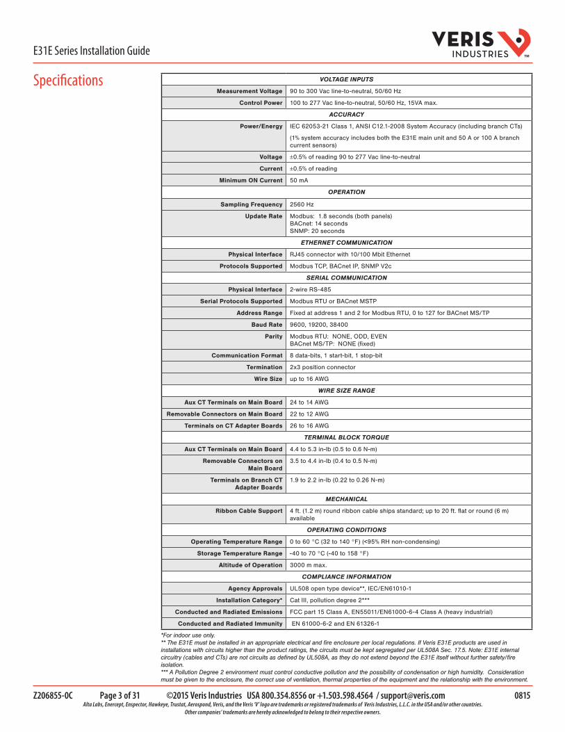
VOLTAGE INPUTS
Measurement Voltage 90 to 300 Vac line-to-neutral, 50/60 Hz
Control Power 100 to 277 Vac line-to-neutral, 50/60 Hz, 15VA max.
ACCURACY
Power/Energy IEC 62053-21 Class 1, ANSI C12.1-2008 System Accuracy (including branch CTs)
(1% system accuracy includes both the E31E main unit and 50 A or 100 A branch current sensors)
Voltage ±0.5% of reading 90 to 277 Vac line-to-neutral
Current ±0.5% of reading
Minimum ON Current 50 mA
OPERATION
Sampling Frequency 2560 Hz
Update Rate Modbus: 1.8 seconds (both panels) BACnet: 14 seconds SNMP: 20 seconds
ETHERNET COMMUNICATION
Physical Interface RJ45 connector with 10/100 Mbit Ethernet
Protocols Supported Modbus TCP, BACnet IP, SNMP V2c
SERIAL COMMUNICATION
Physical Interface 2-wire RS-485
Serial Protocols Supported Modbus RTU or BACnet MSTP
Address Range Fixed at address 1 and 2 for Modbus RTU, 0 to 127 for BACnet MS/TP
Baud Rate 9600, 19200, 38400
Parity Modbus RTU: NONE, ODD, EVEN BACnet MS/TP: NONE (fixed)
Communication Format 8 data-bits, 1 start-bit, 1 stop-bit
Termination 2x3 position connector
Wire Size up to 16 AWG
WIRE SIZE RANGE
Aux CT Terminals on Main Board 24 to 14 AWG
Removable Connectors on Main Board 22 to 12 AWG
Terminals on CT Adapter Boards 26 to 16 AWG
TERMINAL BLOCK TORQUE
Aux CT Terminals on Main Board 4.4 to 5.3 in-lb (0.5 to 0.6 N-m)
Removable Connectors on Main Board
3.5 to 4.4 in-lb (0.4 to 0.5 N-m)
Terminals on Branch CT Adapter Boards
1.9 to 2.2 in-lb (0.22 to 0.26 N-m)
MECHANICAL
Ribbon Cable Support 4 ft. (1.2 m) round ribbon cable ships standard; up to 20 ft. flat or round (6 m) available
OPERATING CONDITIONS
Operating Temperature Range 0 to 60 °C (32 to 140 °F) (<95% RH non-condensing)
Storage Temperature Range -40 to 70 °C (-40 to 158 °F)
Altitude of Operation 3000 m max.
COMPLIANCE INFORMATION
Agency Approvals UL508 open type device**, IEC/EN61010-1
Installation Category* Cat III, pollution degree 2***
Conducted and Radiated Emissions FCC part 15 Class A, EN55011/EN61000-6-4 Class A (heavy industrial)
Conducted and Radiated Immunity EN 61000-6-2 and EN 61326-1
*For indoor use only. ** The E31E must be installed in an appropriate electrical and fire enclosure per local regulations. If Veris E31E products are used in installations with circuits higher than the product ratings, the circuits must be kept segregated per UL508A Sec. 17.5. Note: E31E internal circuitry (cables and CTs) are not circuits as defined by UL508A, as they do not extend beyond the E31E itself without further safety/fire isolation. *** A Pollution Degree 2 environment must control conductive pollution and the possibility of condensation or high humidity. Consideration must be given to the enclosure, the correct use of ventilation, thermal properties of the equipment and the relationship with the environment.
Specifications
Z206855-0C Page 4 of 31 ©2015 Veris Industries USA 800.354.8556 or +1.503.598.4564 / [email protected] 0815 Alta Labs, Enercept, Enspector, Hawkeye, Trustat, Aerospond, Veris, and the Veris ‘V’ logo are trademarks or registered trademarks of Veris Industries, L.L.C. in the USA and/or other countries.
Other companies’ trademarks are hereby acknowledged to belong to their respective owners.
E31E Series Installation GuideTM
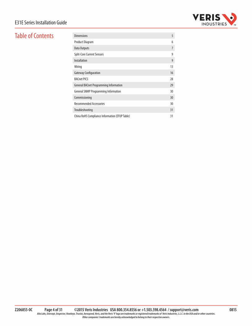
Table of Contents Dimensions 5
Product Diagram 6
Data Outputs 7
Split-Core Current Sensors 9
Installation 9
Wiring 13
Gateway Configuration 16
BACnet PICS 28
General BACnet Programming Information 29
General SNMP Programming Information 30
Commissioning 30
Recommended Accessories 30
Troubleshooting 31
China RoHS Compliance Information (EFUP Table) 31

Z206855-0C Page 5 of 31 ©2015 Veris Industries USA 800.354.8556 or +1.503.598.4564 / [email protected] 0815 Alta Labs, Enercept, Enspector, Hawkeye, Trustat, Aerospond, Veris, and the Veris ‘V’ logo are trademarks or registered trademarks of Veris Industries, L.L.C. in the USA and/or other countries.
Other companies’ trademarks are hereby acknowledged to belong to their respective owners.
E31E Series Installation GuideTM
Dimensions
13.9”(353 mm)
2x: 5.9”(150 mm)
12.8”(325 mm)
8.9”(225 mm)
10.0”(253 mm)
12.1”(307 mm)
8.2”(210 mm)
2.8”(71 mm)
4.6”(117 mm)
2.75”(70 mm)
1.00”(26 mm)
1.00”(26 mm)
Adapter Board
D
ECB
A
D
EB
A
C
E31CT0 50 AmpA = 1.0” (26 mm)B = 0.5” (11 mm)C = 0.4” (10 mm)D = 0.9” (23 mm)E = 1.6” (40 mm)
E31CT1 100 AmpA = 1.5” (37.5 mm)B = 0.6” (16 mm)C = 0.6” (16 mm)D = 1.85” (47 mm)E = 2.1” (53 mm)
E31CT3 200 AmpA = 1.5” (39 mm)B = 1.25” (32 mm)C = 1.25” (32 mm)D = 2.5” (64 mm)E = 2.8” (71 mm)
BE
A
C
D
Current Sensors
Note: The dotted lines indicate dimensions if the two brackets are placed for horizontal mounting. At the factory, the brackets are placed for vertical mounting. See Installation section for more information.

Z206855-0C Page 6 of 31 ©2015 Veris Industries USA 800.354.8556 or +1.503.598.4564 / [email protected] 0815 Alta Labs, Enercept, Enspector, Hawkeye, Trustat, Aerospond, Veris, and the Veris ‘V’ logo are trademarks or registered trademarks of Veris Industries, L.L.C. in the USA and/or other countries.
Other companies’ trademarks are hereby acknowledged to belong to their respective owners.
E31E Series Installation GuideTM
Product Diagram
1. Ethernet port: Provides Ethernet connection for the gateway component.
2. Power LED: Indicates power is applied to the meter.
3. 2x3 RS-485 serial connection.
4. Protective ground connection.
5. Voltage Taps: 1, 2, or 3 phase plus neutral connections. For voltage sensing and power calculations.
6. Control Power Connection: Provides power to operate the meter.
7. Auxiliary CT Inputs: These 0.333 Vac inputs are used for monitoring the main breaker or other high amperage source. Inputs on the left are for panelboard 2; inputs on the right are for panelboard 1.
8. 50-Pin Ribbon Cable Connectors: 4-foot (0.9 m) ribbon cables are provided for easy connection of the adapter boards to this point of the data acquisition board. Other ribbon cable lengths are available (sold separately). The two connectors on the left are for panelboard 2; the two on the right are for panelboard 1.
Connect adapter boards A and B to the correct ribbon cable connectors for each panel. The top connectors are for Board B, and the bottom connectors are for Board A.
Note: Ribbon cables are not included with all E31E models (see Ordering Information).
9. Branch Current Sensors: Up to 84 sensors can be used with the E31E. One of each style is pictured here.
10. Adapter Board: Includes connectors for a ribbon cable and up to 42 current sensors.
12
3
465
7 78
9
10

Z206855-0C Page 7 of 31 ©2015 Veris Industries USA 800.354.8556 or +1.503.598.4564 / [email protected] 0815 Alta Labs, Enercept, Enspector, Hawkeye, Trustat, Aerospond, Veris, and the Veris ‘V’ logo are trademarks or registered trademarks of Veris Industries, L.L.C. in the USA and/or other countries.
Other companies’ trademarks are hereby acknowledged to belong to their respective owners.
E31E Series Installation GuideTM
The E31E provides several types of measurements that give a comprehensive view of power consumption for every monitored load on the panel:
• Real-time measurements: A live and up-to-date view of present power levels and the factors that affect them. • Demand measurements: Averages of values measured over a specified time interval. The time interval (typically
15 minutes) can be set from 10 seconds to more than a day. The demand calculation can be configured to use single intervals or the sliding average of up to 6 sub-intervals. Demand measurements are useful for tracking or graphing load levels over time to correlate with total energy consumption.
• Historic maximum measurements: These measurements store the largest value recorded for a specific measurement since the last time they were cleared. They are useful for identifying peak levels critical to equipment sizing or demand limits in utility agreements.
• Accumulated energy measurements: Ongoing totals of cumulative energy used since the last time the value was cleared. Energy values provide the informational basis for billing, cost allocation, carbon offset, BTU equivalent calculations, and other applications of overall energy use.
• Energy snapshots: Energy totals that only change when the demand intervals are updated. They are samples of the free-running energy accumulators at the end of each demand interval, as configured by the user. These provide energy readings that are easily correlated to the demand values to simplify the tasks of sub-billing and cost allocation.
• Alarms: Provide a warning of excessively high or low current on each branch and aux channel. The user can set two high-level and two low-level thresholds, and a delay time for latching alarms. Alarms are reported as both non-latched events and latched events. Non-latching alarms are active while the current exceeds the threshold, but go inactive if the current returns to a level within the specific thresholds. Latching alarms become active when the current exceeds the threshold for a time period greater than the specified delay and remain active until they are cleared remotely. Alarm status can be polled via any protocol. Via BACnet, Subscribe_COV can be used to generate alarm notifications. Via SNMP, alarms drive SNMP event notifications.
Advanced Features - The E31E supports a number of advanced features. Some are always active, and others are configured manually via Modbus register 62017, BACnet object AV164, or SNMP MIB variable “spanels/panel1/p1Configuration/p1Setup/p1UserDefinedSettings” (OID .1.3.6.1 .4.1.40845.1.30.1.1.6.3.4.0). For models with 42 channels or more, these features are configured independently for each panel.
• Logical meter support: The E31E can be configured to map any set of 1, 2 or 3 channels that are adjacent in the panel to a logical meter, referred to in the point map as a logical circuit, that provides accurate multi-phase measurement totals. Map these logical circuits by writing the desired logical circuit number into a set of registers/data objects provided for each branch and aux channel (per panel).
• The channels assigned to each logical circuit must be adjacent in the panel (usually used for multi-phase breakers), but there are no limitations on where those adjacent channels are aligned in the panel (any position where a multi-phase breaker can be installed). This functionality is always active, but a user selection affects the how the data can be accessed via Modbus. Measurement data via Modbus for logical circuits is presented in two ways, arranged either by logical circuit number (looks more like a collection of individual meters) or by measurement type (arranged similar to the single-phase data section of the point map).
• Legacy point map or alternate logical circuit point map: The E31E can be configured to select a preferred version of the Modbus registers in the address range 4000 to 9999. If enabled (default), the logical circuits by measurement type is active. Otherwise, the legacy point maps for 2-phase and 3-phase breakers used in E3x models with a firmware version earlier than 1.023 is active. The logical circuits functionality can also be accessed via the “Logical Circuits by Circuit” section of the point map (address range 10000 to 45000), regardless of the state of this selection.
• Phase angle measurements: The E31E measures the phase angle of every voltage and current input and presents these measurements (in degrees) in additional data registers/objects. These values are used to verify that current inputs are assigned to the proper voltage phases and to help determine how power factor variations are influenced by current phase changes vs. harmonic distortion. Phase angle measurements are instantaneous and always active.
• User CT phase assignment: In the default mode, the E31E assigns each channel to the corresponding phase that most 3-phase panels implement, so that the user does not have worry about it. The user can opt to replace this self-assignment paradigm with a mode that allows explicit specification of the phase assignment for each channel. The explicit assignments set by the user are stored by the E31E in non-volatile memory.
• Phase angle reference: The E31E measures the phase angle of every current and voltage input. The user can select whether the phase angles are stated relative to an absolute reference (the phase angle of voltage input V1) or relative to the voltage phase assigned to that specific current input channel.
• Signed power: Users can configure the E31E to report power as a signed value indicating whether the power is currently being delivered (imported from the grid) or received (exported to the grid) for channels with generation sources or bi-directional (regenerative) loads. When signed power is disabled, the energy accumulators include all energy measured, regardless of direction. When signed power is enabled, the energy accumulators only include all energy delivered (imported from the grid).
Data Outputs

Z206855-0C Page 8 of 31 ©2015 Veris Industries USA 800.354.8556 or +1.503.598.4564 / [email protected] 0815 Alta Labs, Enercept, Enspector, Hawkeye, Trustat, Aerospond, Veris, and the Veris ‘V’ logo are trademarks or registered trademarks of Veris Industries, L.L.C. in the USA and/or other countries.
Other companies’ trademarks are hereby acknowledged to belong to their respective owners.
E31E Series Installation GuideTM
• Signed power factor: By default the E31E reports power factor as an unsigned value. The user can set it to report as a signed value, where the sign indicates whether the current phase angle leads or lags the corresponding voltage phase.
• Demand/snapshot time interval source: The E31E offers two mechanisms for driving the demand/snapshot time interval, an interval timer or an RTC (real-time clock). The legacy mode (default) uses an interval timer that does not need to be set to an absolute time. When using the interval timer the demand/snapshot interval can be set from 10 to 32767 seconds (over 9 hours). An alternate mode utilizes an RTC set to a specific date and time to synchronize the results with a larger system. The RTC must first be set in order to run and capture demand values and energy snapshots. When power is interrupted, the RTC resets to a default date and time and must be set again in order to run. When using the RTC, the demand/snapshot interval can be set from 10 to 3600 seconds (1 hour).
Monitoring of Mains
Real Time Measurements
Current: multi-phase average and per phase
Current phase angle
Real power (kW): multi-phase total and per phase
Apparent power (kVA): multi-phase total and per phase
Power factor: multi-phase average and per phase
Voltage - L-L: multi-phase average and per phase
Voltage - L-N: multi-phase average and per phase
Frequency (phase A)
Demand MeasurementsCurrent present demand: multi-phase average and per phase
Real Power (kW) present demand: multi-phase average and per phase
Historic Maximums
Maximum instantaneous current: multi-phase average and per phase
Maximum current demand: multi-phase average and per phase
Maximum real power demand: multi-phase total and per phase
Accumulated Energy Energy (kWh): multi-phase total and per phase
Energy Snapshots Energy (kWh): multi-phase total and per phase
Monitoring of Branch Circuits
Real Time Measurements
Current: multi-phase average and per phase
Current phase angle per branch
Real power (kW): multi-phase total and per phase
Apparent power (kVA): multi-phase total and per phase
Power factor: multi-phase average and per phase
Demand MeasurementsCurrent present demand: multi-phase average and per phase
Real power (kW) present demand: multi-phase average and per phase
Historic Maximums
Maximum instantaneous current: multi-phase average and per phase
Maximum current demand: multi-phase average and per phase
Maximum real power demand: multi-phase total and per phase
Accumulated Energy Energy (kWh): multi-phase total and per phase
Energy Snapshots Energy (kWh): multi-phase total and per phase
Modbus Alarms
Alarms
Voltage over/under
Branch current over/under
Mains current over/under
Data Outputs (cont.)

Z206855-0C Page 9 of 31 ©2015 Veris Industries USA 800.354.8556 or +1.503.598.4564 / [email protected] 0815 Alta Labs, Enercept, Enspector, Hawkeye, Trustat, Aerospond, Veris, and the Veris ‘V’ logo are trademarks or registered trademarks of Veris Industries, L.L.C. in the USA and/or other countries.
Other companies’ trademarks are hereby acknowledged to belong to their respective owners.
E31E Series Installation GuideTM
Installation Observe precautions for handling static sensitivedevices to avoid damage to the circuitry thatis not covered under the factory warranty.
Disconnect power to the panel before beginning the installation.
1. Determine where you will mount the E31E measurement unit. The preferred location is inside the enclosure of the panelboard being monitored. If sufficient space is not available there, then mount the unit in an appropriate enclosure nearby. Decide whether to mount the E31E vertically or horizontally. The E31E is shipped with the brackets placed for vertical mounting. If desired, you can move the brackets from the sides to the ends of the housing. Loosen the screws on the ends of the E31E that hold the brackets in place (do not fully remove the screws from the E31E housing). Loosen the screws on the two ends of the housing (do not fully remove the screws from the E31E housing), and set the brackets into their new positions. Tighten all screws.
Vertical Mounting Horizontal Mounting
2. Install the E31E in the panel (hardware not provided). A grounding connection is located on the housing (see below). Use this stud to ground the device when it is mounted on a nonconductive surface.
The protective ground connection on the housing (item 4 in the Product Diagram) should be used if the E31E will not be mounted to a suitably grounded surface. Assure conductivity to the protective ground.
Split-Core Current Sensors
50 A Split-Core CT 100 A Split-Core CT 200 A Split-Core CT
Voltage Rating 300 Vac 300 Vac (CE), 600 Vac (UL) 300 Vac (CE), 600 Vac (UL)
Measurement Range 60 A* 120 A* 240 A*
Temperature 0 to 60 °C 0 to 60 °C 0 to 60 °C
Agency UL 61010-1 Recognized, EN61010-1 UL 61010-1 Recognized, EN61010-1 UL 61010-1 Recognized, EN61010-1*Momentary.
Z206855-0C Page 10 of 31 ©2015 Veris Industries USA 800.354.8556 or +1.503.598.4564 / [email protected] 0815 Alta Labs, Enercept, Enspector, Hawkeye, Trustat, Aerospond, Veris, and the Veris ‘V’ logo are trademarks or registered trademarks of Veris Industries, L.L.C. in the USA and/or other countries.
Other companies’ trademarks are hereby acknowledged to belong to their respective owners.
E31E Series Installation GuideTM
CURR
ENT S
ENSO
R STR
IP
CURR
ENT S
ENSO
R STR
IP
CURR
ENT S
ENSO
R STR
IP
CURR
ENT S
ENSO
R STR
IP
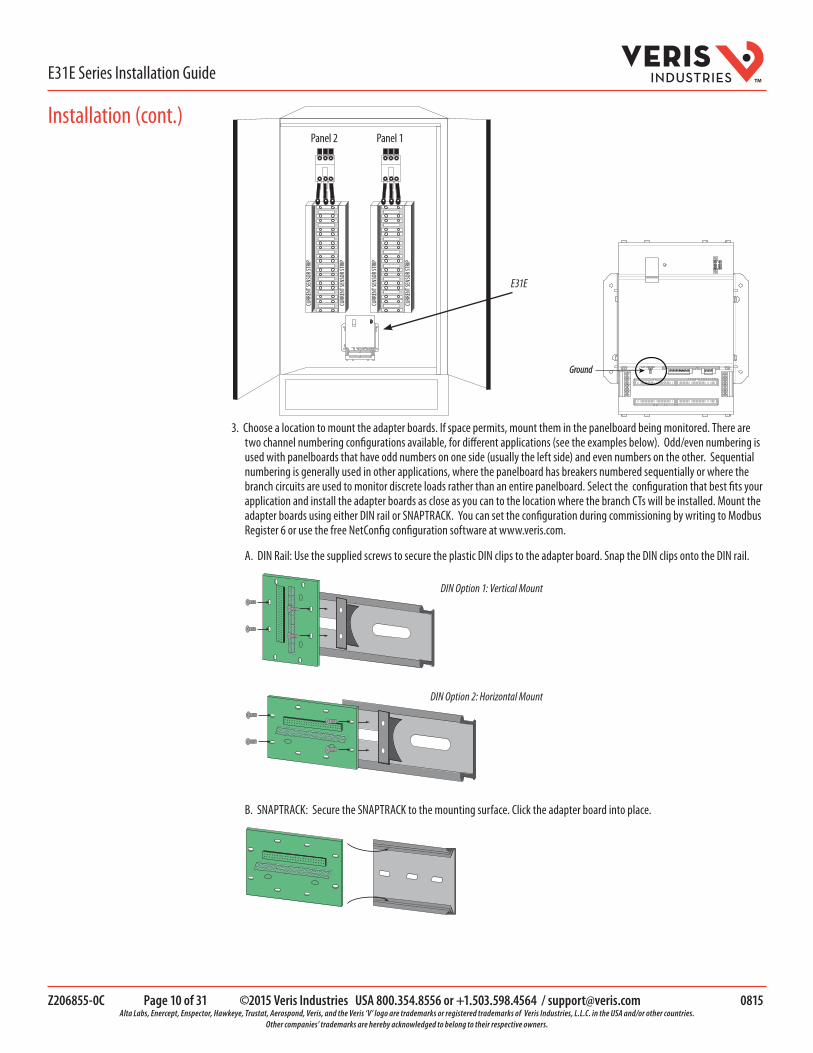
Panel 2 Panel 1
E31E
Ground
3. Choose a location to mount the adapter boards. If space permits, mount them in the panelboard being monitored. There are two channel numbering configurations available, for different applications (see the examples below). Odd/even numbering is used with panelboards that have odd numbers on one side (usually the left side) and even numbers on the other. Sequential numbering is generally used in other applications, where the panelboard has breakers numbered sequentially or where the branch circuits are used to monitor discrete loads rather than an entire panelboard. Select the configuration that best fits your application and install the adapter boards as close as you can to the location where the branch CTs will be installed. Mount the adapter boards using either DIN rail or SNAPTRACK. You can set the configuration during commissioning by writing to Modbus Register 6 or use the free NetConfig configuration software at www.veris.com.
A. DIN Rail: Use the supplied screws to secure the plastic DIN clips to the adapter board. Snap the DIN clips onto the DIN rail.
DIN Option 1: Vertical Mount
DIN Option 2: Horizontal Mount
B. SNAPTRACK: Secure the SNAPTRACK to the mounting surface. Click the adapter board into place.
Installation (cont.)

Z206855-0C Page 11 of 31 ©2015 Veris Industries USA 800.354.8556 or +1.503.598.4564 / [email protected] 0815 Alta Labs, Enercept, Enspector, Hawkeye, Trustat, Aerospond, Veris, and the Veris ‘V’ logo are trademarks or registered trademarks of Veris Industries, L.L.C. in the USA and/or other countries.
Other companies’ trademarks are hereby acknowledged to belong to their respective owners.
E31E Series Installation GuideTM
behavior. If this feature IS enabled, orient the current sensors so that the arrow points toward the load for proper operation.
Note: Clean split-core contact surfaces before closing. The hinge can detach, allowing the base and the top to separate for easier cleaning and installation.
✓
Close current sensors until the clasp clicks into place to ensure that contact
surfaces are firmly seated.
The 50 A CT accepts a maximum #2 AWG (0.384” O.D.) wire with THHN insulation.The 100 A CT accepts a maximum 3/0 AWG (0.584” O.D.) wire with THHN insulation.
The 200 A CT accepts a maximum of 350 MCM wire with THHN insulation.
5. Connect the adapter boards to the main board using ribbon cable. Ribbon cables are keyed to ensure proper installation.
4. Install the current sensors onto the conductors to be monitored.
Orientation Note: If the signed power factor feature is NOT enabled, then the current sensor orientation does not affect meter
6. Connect the current sensors to the terminals on the adapter boards.
Panel 1,Strip A
Panel 1,Strip B
Panel 2,Strip A
Panel 2,Strip B
If the signed power factor feature is NOT enabled, then the current sensor
orientation does not affect meter behavior.If this feature IS enabled, orient the current
sensors so that the arrow points toward the load for proper operation.
Align ribbon cable key with connector
keyhole.
Installation (cont.)

Z206855-0C Page 12 of 31 ©2015 Veris Industries USA 800.354.8556 or +1.503.598.4564 / [email protected] 0815 Alta Labs, Enercept, Enspector, Hawkeye, Trustat, Aerospond, Veris, and the Veris ‘V’ logo are trademarks or registered trademarks of Veris Industries, L.L.C. in the USA and/or other countries.
Other companies’ trademarks are hereby acknowledged to belong to their respective owners.
E31E Series Installation GuideTM
7. Plastic cable ties are included with the product for strain relief. Insert the strain relief device into one of the available holes on the adapter board (A). Gather all current sensor wires connected to that adapter board and secure the cable tie around them (B).
(A) (B)
8. The adapter boards are silk screened with two rows of numbers. For applications that require odd/even branch circuit numbering, use the row designated ODD or EVEN. Odd/even numbering is used with panelboards that have odd numbers on one side (usually the left side) and even numbers on the other. For applications that require sequential numbering, use the number row marked SEQ. Sequential numbering is generally used in other applications, where the panelboard has breakers numbered sequentially or where the branch circuits are used to monitor discrete loads rather than an entire panelboard.
4139373533312927252321191715131197531
123456789101112131415161718192021
ODD
SEQ
BLACK
WHITE
Adapter Board A numbering:
ODD 1 3 5 7 9 11 13 15 17 19 21 23 25 27 29 31 33 35 37 39 41SEQ 21 20 19 18 17 16 15 14 13 12 11 10 9 8 7 6 5 4 3 2 1
42403836343230282624222018161412108642
424140393837363534333231302928272624242322
EVEN
SEQ
BLACK
WHITE
Adapter Board B numbering:
EVEN 2 4 6 8 10 12 14 16 18 20 22 24 26 28 30 32 34 36 38 40 42SEQ 22 23 24 25 26 27 28 29 30 31 32 33 34 35 36 37 38 39 40 41 42
Aux CT Installation
1. Connect 0.333 Vac current transducers (CTs) to the mains or other conductors to be monitored. Refer to the appropriate CT installation instructions for further information.
E30 C
URRE
NT SE
NSOR
STRIP
E30 C
URRE
NT SE
NSOR
STRIP
E30 C
URRE
NT SE
NSOR
STRIP
E30 C
URRE
NT SE
NSOR
STRIP
Panel 2 Panel 1
Note: The E31E measures and reports the phase angle of each voltage input and each CT (when there is active current through the primary of that CT). Use the NetConfig configuration software tool to view the phase angles of active circuits to help verify that those circuits are connected to and mapped to the proper voltage phases. See the E3x Commissioning Guide for instructions on how to download and operate the tool from a PC.
Installation (cont.)
Z206855-0C Page 13 of 31 ©2015 Veris Industries USA 800.354.8556 or +1.503.598.4564 / [email protected] 0815 Alta Labs, Enercept, Enspector, Hawkeye, Trustat, Aerospond, Veris, and the Veris ‘V’ logo are trademarks or registered trademarks of Veris Industries, L.L.C. in the USA and/or other countries.
Other companies’ trademarks are hereby acknowledged to belong to their respective owners.
E31E Series Installation GuideTM
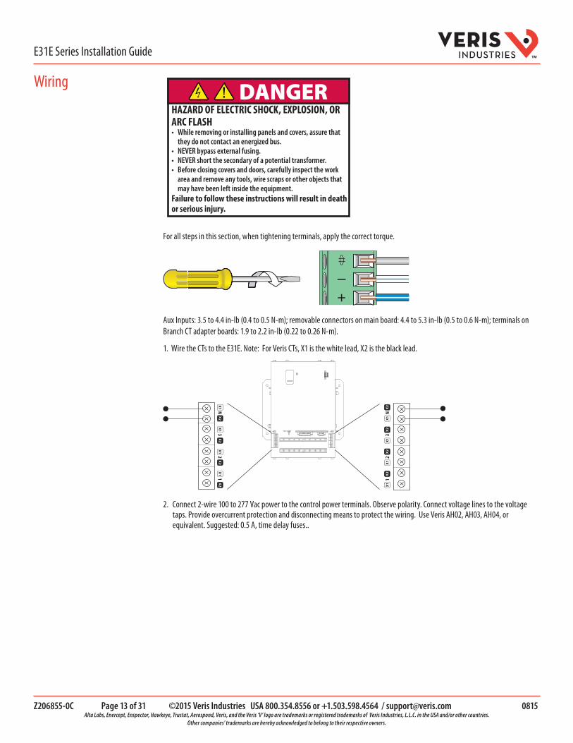
DANGERHAZARD OF ELECTRIC SHOCK, EXPLOSION, OR ARC FLASH• While removing or installing panels and covers, assure that
they do not contact an energized bus.• NEVER bypass external fusing.• NEVER short the secondary of a potential transformer.• Before closing covers and doors, carefully inspect the work
area and remove any tools, wire scraps or other objects that may have been left inside the equipment.
Failure to follow these instructions will result in death or serious injury.
For all steps in this section, when tightening terminals, apply the correct torque.
–+
Aux Inputs: 3.5 to 4.4 in-lb (0.4 to 0.5 N-m); removable connectors on main board: 4.4 to 5.3 in-lb (0.5 to 0.6 N-m); terminals on Branch CT adapter boards: 1.9 to 2.2 in-lb (0.22 to 0.26 N-m).
1. Wire the CTs to the E31E. Note: For Veris CTs, X1 is the white lead, X2 is the black lead.
1 2
3 N
X1
X1
X1
X1
X2
X2
X2
X2
N 3
2 1
X1
X1
X1
X1
X2
X2
X2
X2
2. Connect 2-wire 100 to 277 Vac power to the control power terminals. Observe polarity. Connect voltage lines to the voltage taps. Provide overcurrent protection and disconnecting means to protect the wiring. Use Veris AH02, AH03, AH04, or equivalent. Suggested: 0.5 A, time delay fuses..
Wiring

Z206855-0C Page 14 of 31 ©2015 Veris Industries USA 800.354.8556 or +1.503.598.4564 / [email protected] 0815 Alta Labs, Enercept, Enspector, Hawkeye, Trustat, Aerospond, Veris, and the Veris ‘V’ logo are trademarks or registered trademarks of Veris Industries, L.L.C. in the USA and/or other countries.
Other companies’ trademarks are hereby acknowledged to belong to their respective owners.
E31E Series Installation GuideTM
Voltage taps are shared by both panels.
L-N V1 V2/NL-L
Voltage Inputs90 to 300 V 50/60 Hz
N V3 V2 V1
Control Power100 to 277 V 50/60 Hz 15 VA
V1 V2/N
Wiring configurations:
3-wire (ungrounded)Delta
Corner-groundedDelta
4-wireWye
3-wireSplit-phase
2-wireSingle-phase
120/240V High-LegDelta
L3 L3 L3L3
XL2 L1 L2 L1 L2 L1
L2
L1
L1N
N
NN
N
L2 L1
120 V/240 V Delta High Leg (where the center tap of one of the three phase-to-phase transformers is grounded): the E3x supports these applications, as long as the line-to neutral voltage [especially of the High Leg] does not exceed 300 Vac (as in North American 120/240 V High Leg Delta configurations).
In 3-wire (ungrounded) Delta applications, the E3x supports these applications with the following caveats:
Control Power for the meter cannot exceed 277 Vac. In applications where the L-L voltage is 277 Vac or less (e.g. 208 V line-to-line) it can be connected to two of the phases being monitored without exceeding the limit. For higher voltages (e.g. 480 V line-to-line), this must be supplied from a source that is 277 Vac or less. It could be a separate source or a transformer can be used to step it down from two of the phases being measured.
All of the CT inputs (both branches and Aux inputs) are neutral-referenced. One side of each CT is essentially connected directly to the neutral voltage input. If this is left floating, the solid-core CT strips, split-core CT adapter boards and all CTs will float at the same potential (while the panel is energized). This does not present a risk to the equipment as long as it is within 300 V of ground, but should be considered from a safety perspective in the overall application. The E3x will provide measurements in this application with the accuracy specified, with the exception of line-to-neutral voltages, which will be calculated and reported, based on a derived virtual neutral voltage, even though they are not relevant.
Corner-grounded delta: the E3x does not support these applications at any voltage level.
The E3x supports measurement of all 4-wire Wye, 3-wire split-phase and 2-wire single phase and configurations that operate between 90 and 300 Vac line-to neutral.
3. Connect the 2-wire Modbus RS-485 network.
Wiring (cont.)

Z206855-0C Page 15 of 31 ©2015 Veris Industries USA 800.354.8556 or +1.503.598.4564 / [email protected] 0815 Alta Labs, Enercept, Enspector, Hawkeye, Trustat, Aerospond, Veris, and the Veris ‘V’ logo are trademarks or registered trademarks of Veris Industries, L.L.C. in the USA and/or other countries.
Other companies’ trademarks are hereby acknowledged to belong to their respective owners.
E31E Series Installation GuideTM
RS-485S–+
S–+
4. Mechanically secure the RS-485 cable(s) where they enter the electrical panel.
5. If using Modbus RTU or BACnet MS/TP protocol, connect serial cable(s) from the RS-485 loop to the serial connector on the E31E. Connect all RS-485 devices in a daisy-chain, and properly terminate the chain. Two sets of connections are provided to simplify daisy-chain connections and enable retention of each wire. Follow all applicable wiring and termination connection guidelines for the standard in use. Note that while both the Modbus RTU and BACnet MS/TP standards identify requirements for RS-485 line polarization/bias and termination, the value and placement of these resistors varies for each standard. The E31E does not implement any RS-485 line polarization/bias or termination internally. For the RS-485 cable, use shielded, twisted-pair wire that is voltage-rated for the installation. The shield is not internally connected to Earth Ground. Connect the shield to Earth Ground somewhere on the RS-485 bus (single point connection only).
RS-485S–+
S–+
RS485 cable
120 Ω terminator where specified
by the applicable standard
6. Connect an Ethernet cable to a local PC. Secure a ferrite filter (included) around the Ethernet cable to ensure the device
meets emission requirements. Use the PC to configure the gateway (see “Gateway Configuration” on page 16 for further information). Note: 100 to 277 Vac must be applied to the control power inputs to supply power to the gateway during configuration.
Wiring (cont.)

Z206855-0C Page 16 of 31 ©2015 Veris Industries USA 800.354.8556 or +1.503.598.4564 / [email protected] 0815 Alta Labs, Enercept, Enspector, Hawkeye, Trustat, Aerospond, Veris, and the Veris ‘V’ logo are trademarks or registered trademarks of Veris Industries, L.L.C. in the USA and/or other countries.
Other companies’ trademarks are hereby acknowledged to belong to their respective owners.
E31E Series Installation GuideTM
7. Once configured, disconnect the local PC. If desired (and the device is configured for operation on the network), connect the E31E directly to the network for ongoing access to the GUI even if primarily using a serial protocol to access and control the E31E.
A quali�ed person is one who has skills and knowledgerelated to the construction and operation of this electricalequipment and installations, and has received safety trainingto recognize and avoid the hazards involved. NEC Article 100If this product is used in a manner not speci�ed by themanufacturer, the protection provided by the product may beimpaired. No responsibility is assumed by the manufacturer for any consequences arising out of the use of this material.
DANGERHAZARD OF ELECTRIC SHOCK, EXPLOSION, OR
ARC FLASH• This product must be installed inside a suitable fire and
electrical enclosure.• Follow safe electrical work practices. See NFPA 70E in
the USA, or applicable local codes.• This equipment must only be installed and serviced by
qualified electrical personnel.• Do not use this product for life or safety applications.• Do not install this product in hazardous or classified locations.• Read, understand and follow the instructions before
installing this product.• Turn off all power supplying equipment before working on or
inside the equipment.• Product may use multiple voltage/power sources. Disconnect ALL sources before servicing.• Use a properly rated voltage sensing device to confirm that
power is off. DO NOT depend on this product for voltage indication.
• Current transformer secondaries (current mode) must be shorted or connected to a burden at all times.
• Products rated only for basic insulation must be installed on insulated conductors.
• Replace all doors, covers and protective devices before powering the equipment.
• The installer is responsible for conformance to all applicable codes.
Failure to follow these instructions will result in death or serious injury.
Gateway Configuration
Z206855-0C Page 17 of 31 ©2015 Veris Industries USA 800.354.8556 or +1.503.598.4564 / [email protected] 0815 Alta Labs, Enercept, Enspector, Hawkeye, Trustat, Aerospond, Veris, and the Veris ‘V’ logo are trademarks or registered trademarks of Veris Industries, L.L.C. in the USA and/or other countries.
Other companies’ trademarks are hereby acknowledged to belong to their respective owners.
E31E Series Installation GuideTM
Accessing the Graphical User Interface (GUI)
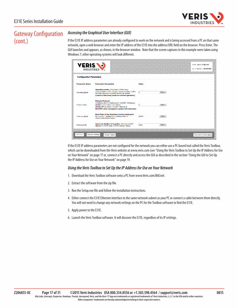
If the E31E IP address parameters are already configured to work on the network and is being accessed from a PC on that same network, open a web browser and enter the IP address of the E31E into the address/URL field on the browser. Press Enter. The GUI launches and appears, as shown, in the browser window. Note that the screen captures in this example were taken using Windows 7; other operating systems will look different.
If the E31E IP address parameters are not configured for the network you can either use a PC-based tool called the Veris Toolbox, which can be downloaded from the Veris website at www.veris.com (see “Using the Veris Toolbox to Set Up the IP Address for Use on Your Network” on page 17 or, connect a PC directly and access the GUI as described in the section “Using the GUI to Set Up the IP Address for Use on Your Network” on page 19.
Using the Veris Toolbox to Set Up the IP Address for Use on Your Network
1. Download the Veris Toolbox software onto a PC from www.Veris.com/BACnet.
2. Extract the software from the zip file.
3. Run the Setup.exe file and follow the installation instructions.
4. Either connect the E31E Ethernet interface to the same network subnet as your PC or connect a cable between them directly. You will not need to change any network settings on the PC for the Toolbox software to find the E31E.
5. Apply power to the E31E.
6. Launch the Veris Toolbox software. It will discover the E31E, regardless of its IP settings.
Gateway Configuration (cont.)

Z206855-0C Page 18 of 31 ©2015 Veris Industries USA 800.354.8556 or +1.503.598.4564 / [email protected] 0815 Alta Labs, Enercept, Enspector, Hawkeye, Trustat, Aerospond, Veris, and the Veris ‘V’ logo are trademarks or registered trademarks of Veris Industries, L.L.C. in the USA and/or other countries.
Other companies’ trademarks are hereby acknowledged to belong to their respective owners.
E31E Series Installation GuideTM
7. Click the gear-shaped configuration icon near the right edge of the window on the line that shows the device you wish to configure. The Configure Device dialog will appear.
8. Click the Network Settings button. The Device Network Settings dialog will appear. This dialog shows all the current IP settings of the E31E.
9. Enter the network settings needed to operate properly on your network.
Gateway Configuration (cont.)
Z206855-0C Page 19 of 31 ©2015 Veris Industries USA 800.354.8556 or +1.503.598.4564 / [email protected] 0815 Alta Labs, Enercept, Enspector, Hawkeye, Trustat, Aerospond, Veris, and the Veris ‘V’ logo are trademarks or registered trademarks of Veris Industries, L.L.C. in the USA and/or other countries.
Other companies’ trademarks are hereby acknowledged to belong to their respective owners.
E31E Series Installation GuideTM
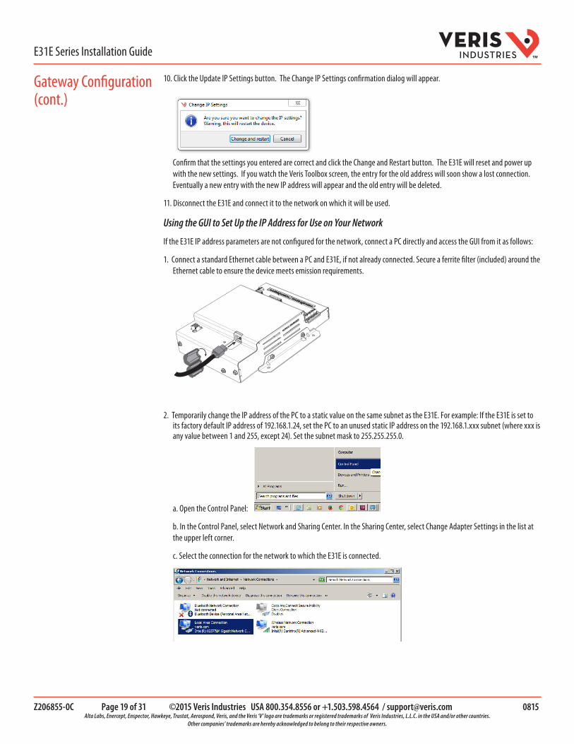
10. Click the Update IP Settings button. The Change IP Settings confirmation dialog will appear.
Confirm that the settings you entered are correct and click the Change and Restart button. The E31E will reset and power up with the new settings. If you watch the Veris Toolbox screen, the entry for the old address will soon show a lost connection. Eventually a new entry with the new IP address will appear and the old entry will be deleted.
11. Disconnect the E31E and connect it to the network on which it will be used.
Using the GUI to Set Up the IP Address for Use on Your Network
If the E31E IP address parameters are not configured for the network, connect a PC directly and access the GUI from it as follows:
1. Connect a standard Ethernet cable between a PC and E31E, if not already connected. Secure a ferrite filter (included) around the Ethernet cable to ensure the device meets emission requirements.
2. Temporarily change the IP address of the PC to a static value on the same subnet as the E31E. For example: If the E31E is set to its factory default IP address of 192.168.1.24, set the PC to an unused static IP address on the 192.168.1.xxx subnet (where xxx is any value between 1 and 255, except 24). Set the subnet mask to 255.255.255.0.
a. Open the Control Panel:
b. In the Control Panel, select Network and Sharing Center. In the Sharing Center, select Change Adapter Settings in the list at the upper left corner.
c. Select the connection for the network to which the E31E is connected.
Gateway Configuration (cont.)

Z206855-0C Page 20 of 31 ©2015 Veris Industries USA 800.354.8556 or +1.503.598.4564 / [email protected] 0815 Alta Labs, Enercept, Enspector, Hawkeye, Trustat, Aerospond, Veris, and the Veris ‘V’ logo are trademarks or registered trademarks of Veris Industries, L.L.C. in the USA and/or other countries.
Other companies’ trademarks are hereby acknowledged to belong to their respective owners.
E31E Series Installation GuideTM
When the Local Area Connection Status dialog box appears, click on Properties.
d. Highlight Internet Protocol Version 4 (TCP/IPv4), and click OK.
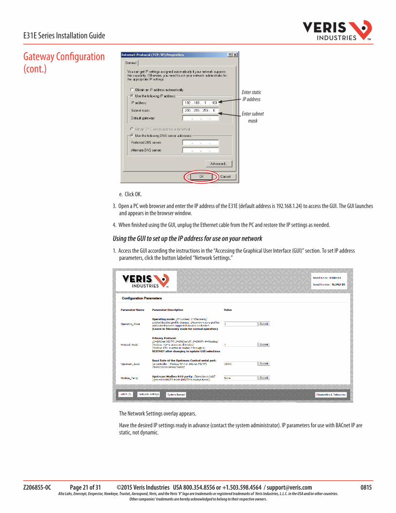
e. Select <Use the following IP Address>. Make note of the IP address that appears, then enter the static IP address (e.g. if the E31E Series is still set to its default address of 192.168.1.24, then change it to 192.168.1.100). Enter 255.255.255.0 for the subnet mask. Click OK.
Gateway Configuration (cont.)
Z206855-0C Page 21 of 31 ©2015 Veris Industries USA 800.354.8556 or +1.503.598.4564 / [email protected] 0815 Alta Labs, Enercept, Enspector, Hawkeye, Trustat, Aerospond, Veris, and the Veris ‘V’ logo are trademarks or registered trademarks of Veris Industries, L.L.C. in the USA and/or other countries.
Other companies’ trademarks are hereby acknowledged to belong to their respective owners.
E31E Series Installation GuideTM
Enter static IP address
Enter subnet mask
e. Click OK.
3. Open a PC web browser and enter the IP address of the E31E (default address is 192.168.1.24) to access the GUI. The GUI launches and appears in the browser window.
4. When finished using the GUI, unplug the Ethernet cable from the PC and restore the IP settings as needed.
Using the GUI to set up the IP address for use on your network
1. Access the GUI according the instructions in the “Accessing the Graphical User Interface (GUI)” section. To set IP address parameters, click the button labeled “Network Settings.”
The Network Settings overlay appears.
Have the desired IP settings ready in advance (contact the system administrator). IP parameters for use with BACnet IP are static, not dynamic.
Gateway Configuration (cont.)

Z206855-0C Page 22 of 31 ©2015 Veris Industries USA 800.354.8556 or +1.503.598.4564 / [email protected] 0815 Alta Labs, Enercept, Enspector, Hawkeye, Trustat, Aerospond, Veris, and the Veris ‘V’ logo are trademarks or registered trademarks of Veris Industries, L.L.C. in the USA and/or other countries.
Other companies’ trademarks are hereby acknowledged to belong to their respective owners.
E31E Series Installation GuideTM
2. Set the IP address for use on the BACnet/IP network:
a. Enter the desired IP address in the N1_IP_Address field (in the format xxx.xxx.xxx.xxx)
b. If necessary, change the Subnet Mask by entering the appropriate new value in the N1_Netmask field
c. If the E31E is connected to an Ethernet gateway, enter its IP address in the Default Gateway field. This is especially critical if the E31E will be used as a BACnet BBMD device.
d. Click the Update IP settings button. The E31E changes its settings.
e. Click the System Restart button and wait for the E31E to fully initialize. The GUI will connect when the E31E is installed on a network that matches the settings and the new IP address is entered into a web browser on a PC properly configured for the network.
Using the GUI to Set the Configuration Parameters for the Communication Protocols
Access the GUI according the instructions in the “Accessing the Graphical User Interface (GUI)” section.
The home screen on the GUI provides fields for configuration of the E31E. The E31E has four primary modes of operation, each of which support a different combination of protocols. Each option field has a Submit button to the right. When changing the value
Gateway Configuration (cont.)
Z206855-0C Page 23 of 31 ©2015 Veris Industries USA 800.354.8556 or +1.503.598.4564 / [email protected] 0815 Alta Labs, Enercept, Enspector, Hawkeye, Trustat, Aerospond, Veris, and the Veris ‘V’ logo are trademarks or registered trademarks of Veris Industries, L.L.C. in the USA and/or other countries.
Other companies’ trademarks are hereby acknowledged to belong to their respective owners.
E31E Series Installation GuideTM
in any field, click Submit to store the new value. The GUI prompts the user to restart the system. If multiple values are changed, it is easiest to submit all changes and restart only once when finished with the whole screen. To restart, click the System Restart button in the row at the bottom of the screen. The restart takes several seconds, during which the server may lose its connection. Messages appear at the top of the screen indicating current status, but do not perform any actions. Simply allow the tool to complete the restart cycle.
The first selection in the GUI is Operating_Mode, which has two choices:
1. Locked: used for all normal product operation. It is provided as a tool for high-level technical support. The gateway retains its current profile configuration when powered. 2. Discovery mode (default): deletes profiles and rediscovers them when the device is powered again. The results are the same, unless the profile configuration is intentionally altered. Profile selection and discovery are especially important when using BACnet or SNMP protocols. For normal operation, always use discovery mode.
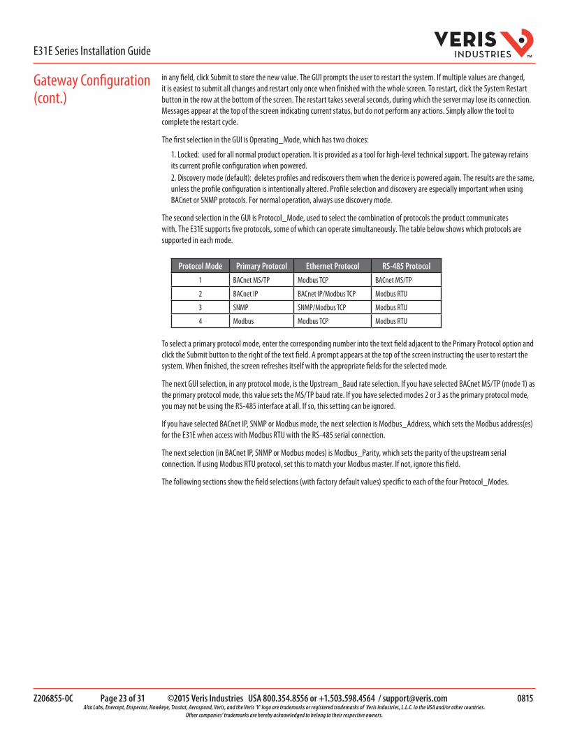
The second selection in the GUI is Protocol_Mode, used to select the combination of protocols the product communicates with. The E31E supports five protocols, some of which can operate simultaneously. The table below shows which protocols are supported in each mode.
Protocol Mode Primary Protocol Ethernet Protocol RS-485 Protocol
1 BACnet MS/TP Modbus TCP BACnet MS/TP
2 BACnet IP BACnet IP/Modbus TCP Modbus RTU
3 SNMP SNMP/Modbus TCP Modbus RTU
4 Modbus Modbus TCP Modbus RTU To select a primary protocol mode, enter the corresponding number into the text field adjacent to the Primary Protocol option and click the Submit button to the right of the text field. A prompt appears at the top of the screen instructing the user to restart the system. When finished, the screen refreshes itself with the appropriate fields for the selected mode.
The next GUI selection, in any protocol mode, is the Upstream_Baud rate selection. If you have selected BACnet MS/TP (mode 1) as the primary protocol mode, this value sets the MS/TP baud rate. If you have selected modes 2 or 3 as the primary protocol mode, you may not be using the RS-485 interface at all. If so, this setting can be ignored.
If you have selected BACnet IP, SNMP or Modbus mode, the next selection is Modbus_Address, which sets the Modbus address(es) for the E31E when access with Modbus RTU with the RS-485 serial connection.
The next selection (in BACnet IP, SNMP or Modbus modes) is Modbus_Parity, which sets the parity of the upstream serial connection. If using Modbus RTU protocol, set this to match your Modbus master. If not, ignore this field.
The following sections show the field selections (with factory default values) specific to each of the four Protocol_Modes.
Gateway Configuration (cont.)
Z206855-0C Page 24 of 31 ©2015 Veris Industries USA 800.354.8556 or +1.503.598.4564 / [email protected] 0815 Alta Labs, Enercept, Enspector, Hawkeye, Trustat, Aerospond, Veris, and the Veris ‘V’ logo are trademarks or registered trademarks of Veris Industries, L.L.C. in the USA and/or other countries.
Other companies’ trademarks are hereby acknowledged to belong to their respective owners.
E31E Series Installation GuideTM
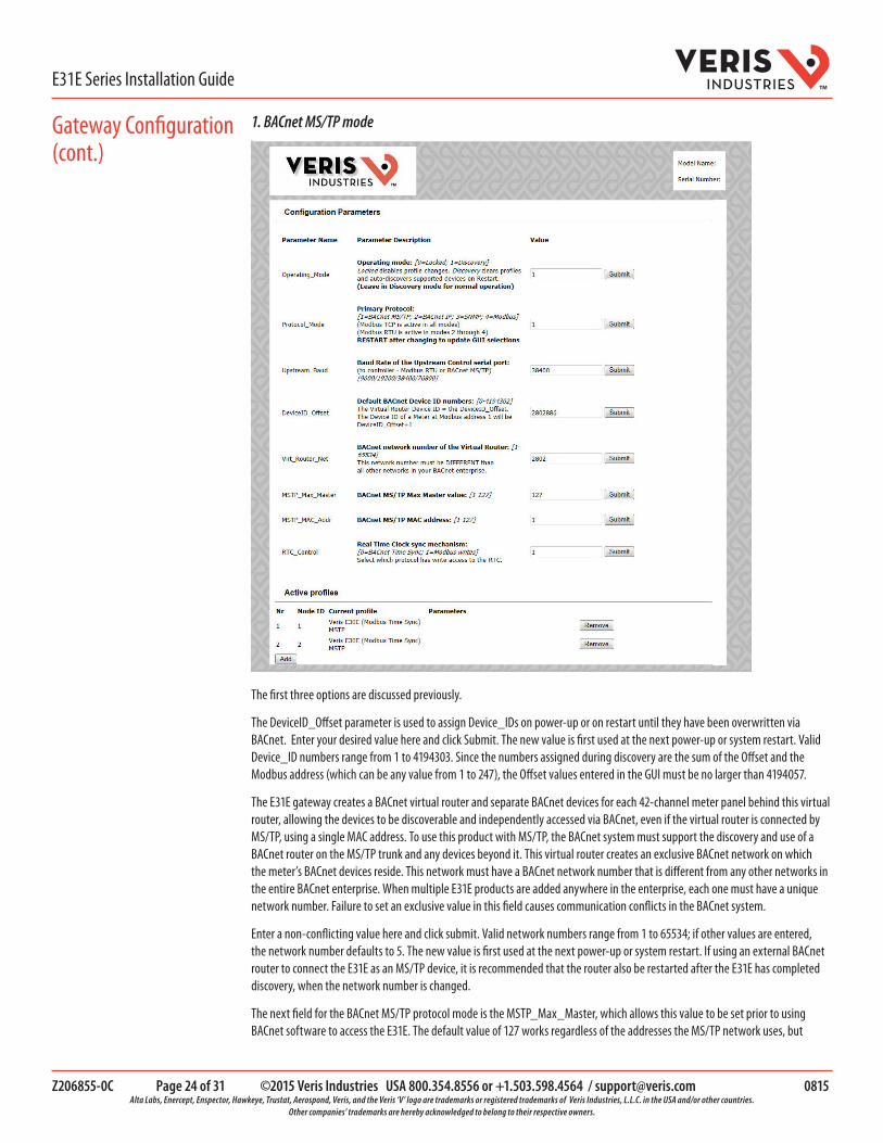
1. BACnet MS/TP mode
The first three options are discussed previously.
The DeviceID_Offset parameter is used to assign Device_IDs on power-up or on restart until they have been overwritten via BACnet. Enter your desired value here and click Submit. The new value is first used at the next power-up or system restart. Valid Device_ID numbers range from 1 to 4194303. Since the numbers assigned during discovery are the sum of the Offset and the Modbus address (which can be any value from 1 to 247), the Offset values entered in the GUI must be no larger than 4194057.
The E31E gateway creates a BACnet virtual router and separate BACnet devices for each 42-channel meter panel behind this virtual router, allowing the devices to be discoverable and independently accessed via BACnet, even if the virtual router is connected by MS/TP, using a single MAC address. To use this product with MS/TP, the BACnet system must support the discovery and use of a BACnet router on the MS/TP trunk and any devices beyond it. This virtual router creates an exclusive BACnet network on which the meter’s BACnet devices reside. This network must have a BACnet network number that is different from any other networks in the entire BACnet enterprise. When multiple E31E products are added anywhere in the enterprise, each one must have a unique network number. Failure to set an exclusive value in this field causes communication conflicts in the BACnet system.
Enter a non-conflicting value here and click submit. Valid network numbers range from 1 to 65534; if other values are entered, the network number defaults to 5. The new value is first used at the next power-up or system restart. If using an external BACnet router to connect the E31E as an MS/TP device, it is recommended that the router also be restarted after the E31E has completed discovery, when the network number is changed.
The next field for the BACnet MS/TP protocol mode is the MSTP_Max_Master, which allows this value to be set prior to using BACnet software to access the E31E. The default value of 127 works regardless of the addresses the MS/TP network uses, but
Gateway Configuration (cont.)

Z206855-0C Page 25 of 31 ©2015 Veris Industries USA 800.354.8556 or +1.503.598.4564 / [email protected] 0815 Alta Labs, Enercept, Enspector, Hawkeye, Trustat, Aerospond, Veris, and the Veris ‘V’ logo are trademarks or registered trademarks of Veris Industries, L.L.C. in the USA and/or other countries.
Other companies’ trademarks are hereby acknowledged to belong to their respective owners.
E31E Series Installation GuideTM
selecting a lower value may optimize the network. Do not set this value lower than the highest address on the network. To set this value via BACnet, write to the Max_Master property of the device object for the E31E’s virtual router.
The next field for the BACnet MS/TP protocol mode is the MSTP_MAC_Addr, which sets the MAC address for the virtual router. The E31E panel(s) are devices on the internal BACnet network and are not directly addressable as MAC addresses on the MS/TP network.
The final field for the BACnet MS/TP mode is RTC_Control, which selects which protocol (BACnet or Modbus) has write access to the RTC. If 0 (BACnet) is selected, the RTC is set using the BACnet Time Synchronization service. If 1 (Modbus) is selected, the RTC is set by writing to the appropriate Modbus registers.
2. BACnet IP mode
BACnet IP mode uses the same DeviceID_Offset, Virt_Router_Net and RTC_Control parameters described above for BACnet MS/TP mode. One additional parameter, BACnet_IP_Port, is used to set the UDP port. Most BACnet systems use the default port (47808 decimal, 0xBAC0 hex) that is recommended in the BACnet standard as the only UDP port. Some large systems need to segment the enterprise and use more than port. If so, enter the number of the port you need to use to access this device. BACnet IP mode does not use MSTP_Max_Master or MSTP_MAC_Addr.
Gateway Configuration (cont.)
Z206855-0C Page 26 of 31 ©2015 Veris Industries USA 800.354.8556 or +1.503.598.4564 / [email protected] 0815 Alta Labs, Enercept, Enspector, Hawkeye, Trustat, Aerospond, Veris, and the Veris ‘V’ logo are trademarks or registered trademarks of Veris Industries, L.L.C. in the USA and/or other countries.
Other companies’ trademarks are hereby acknowledged to belong to their respective owners.
E31E Series Installation GuideTM
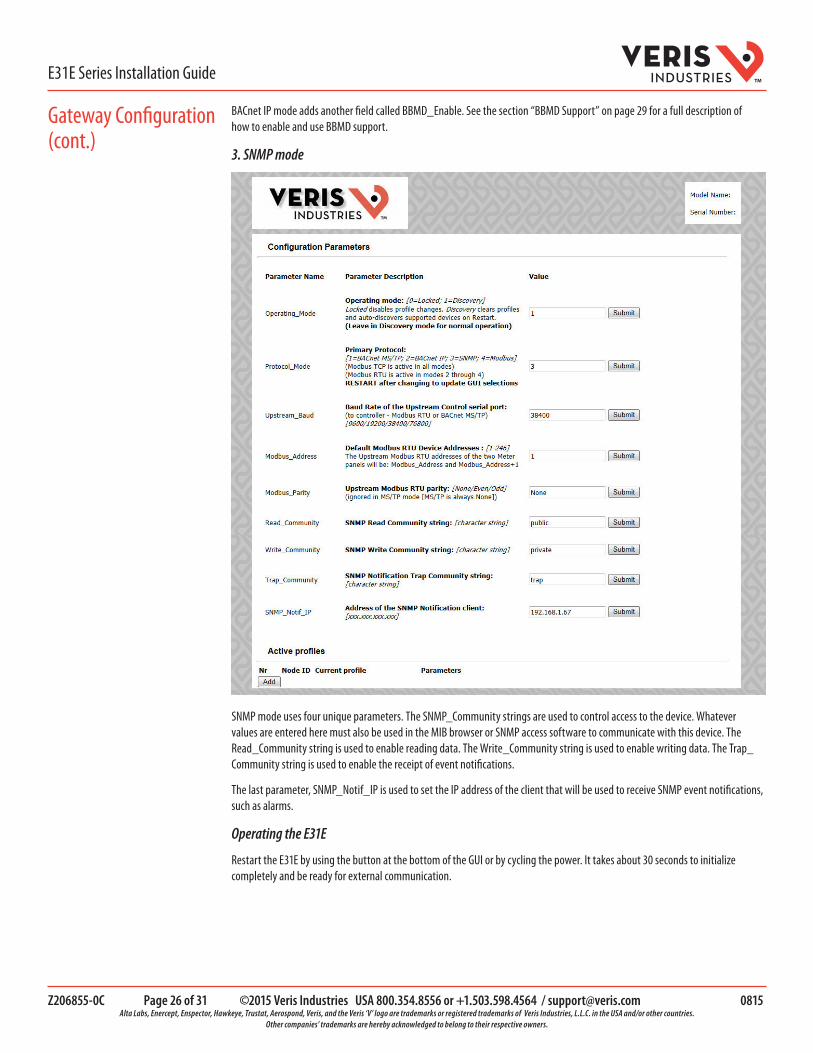
BACnet IP mode adds another field called BBMD_Enable. See the section “BBMD Support” on page 29 for a full description of how to enable and use BBMD support.
3. SNMP mode
SNMP mode uses four unique parameters. The SNMP_Community strings are used to control access to the device. Whatever values are entered here must also be used in the MIB browser or SNMP access software to communicate with this device. The Read_Community string is used to enable reading data. The Write_Community string is used to enable writing data. The Trap_Community string is used to enable the receipt of event notifications.
The last parameter, SNMP_Notif_IP is used to set the IP address of the client that will be used to receive SNMP event notifications, such as alarms.
Operating the E31E
Restart the E31E by using the button at the bottom of the GUI or by cycling the power. It takes about 30 seconds to initialize completely and be ready for external communication.
Gateway Configuration (cont.)

Z206855-0C Page 27 of 31 ©2015 Veris Industries USA 800.354.8556 or +1.503.598.4564 / [email protected] 0815 Alta Labs, Enercept, Enspector, Hawkeye, Trustat, Aerospond, Veris, and the Veris ‘V’ logo are trademarks or registered trademarks of Veris Industries, L.L.C. in the USA and/or other countries.
Other companies’ trademarks are hereby acknowledged to belong to their respective owners.
E31E Series Installation GuideTM
BACnet Network Management – Important Steps to Avoid Conflicts
BACnet configuration uses two default settings that might need to be changed, depending on the application.
a. Virtual router network ID number. Every logical network segment (IP subnet, MS/TP trunk, etc.) in an entire system must have a (16-bit) network ID number that is unique from all other BACnet networks in the enterprise. The BACnet network administrator assigns this network ID so that no two ID numbers conflict (whether using BACnet/IP or MS/TP). Within each segment, every device is physically identified by the combination of its 8-bit MAC address and the 16-bit network ID number.
To support multiple meter panels (panel 1 and panel 2 are separate) with a single gateway, the E31E creates a virtual BACnet router that presents multiple BACnet devices using a single (its own) MS/TP MAC address. Each E31E must have its own (internal) network ID, and it creates a device object for itself and one for each Modbus address discovered.
The factory default network address is 50 (decimal). If that number is already in use in the system, assign a unique address using the graphical user interface (GUI) on the built-in web server (this requires an Ethernet connection to a web browser; see “General BACnet Programming Information” on page 29 for instructions on changing configuration settings using the GUI). Valid network numbers range from 1 to 65534; if other values are entered, the network number defaults to 5.
b. Device_ID Offset. Every BACnet device must have a BACnet Device_ID number that is unique throughout the entire enterprise. Since the E31E presents every Modbus meter as a BACnet device, each connected meter that has a Modbus address must have a BACnet Device_ID.
By default, each device discovered receives a Device_ID number that is the sum of an offset value (default is 50000) and the Modbus address of the device. If these Device_ID numbers cause a conflict with existing devices in the system, or if the system includes multiple E31E Series, change the Device_ID numbers before connecting the E31E to the system. This can be managed one of two ways:
i. Connect to the E31E directly (offline from the system) with the devices (meters). After the E31E discovers the devices and assigns their default ID numbers, the user can choose new Device_ID values and write these to each device using BACnet software. Subsequent discoveries will not overwrite these values with defaults even if the E31E is then set to Discovery mode.
ii. Use the GUI on the built-in web server to modify the offset value used to calculate default Device_IDs in the discovery process (this requires an Ethernet connection to a web browser; see “General BACnet Programming Information” on page 29 for instructions on changing configuration settings using the GUI). The E31E retains this offset value and uses it to assign Device_ID numbers every time power is cycled if the E31E is in Discovery mode. Valid Device_ID numbers range from 1 to 4194303. Since the numbers assigned during discovery are the sum of the Offset and the Modbus address (which can be any value from 1 to 247), any Offset values entered in the GUI must be less than 4194057.
Gateway Configuration (cont.)

Z206855-0C Page 28 of 31 ©2015 Veris Industries USA 800.354.8556 or +1.503.598.4564 / [email protected] 0815 Alta Labs, Enercept, Enspector, Hawkeye, Trustat, Aerospond, Veris, and the Veris ‘V’ logo are trademarks or registered trademarks of Veris Industries, L.L.C. in the USA and/or other countries.
Other companies’ trademarks are hereby acknowledged to belong to their respective owners.
E31E Series Installation GuideTM
BACnet PICS (Protocol Implementation Conformance Statement)
Vendor Name: Veris IndustriesBACnet Vendor ID 133Product Name: E31E Series Branch Circuit MonitorProduct Model Number: <Model Number>Product Description: Branch Circuit MonitorBACnet Protocol Version: Version 1 Revision 12
BACnet Standardized Device Profile (Annex L) - [Note: E31E incorporates a gateway device]• BACnet Application Specific Controller (B-ASC)
BACnet Interoperability Building Blocks Supported (Annex K):• K.1.2 BIBB - Data Sharing - ReadProperty-B (DS-RP-B)• K.1.4 BIBB - Data Sharing - ReadPropertyMultiple-B (DS-RPM-B)• K.1.8 BIBB - Data Sharing - WriteProperty-B (DS-WP-B)• K.1.10 BIBB - Data Sharing - WritePropertyMultiple-B (DS-WPM-B)• K.1.12 BIBB - Data Sharing - COV-B (DS-COV-B)• K.2.2 BIBB - Alarm and Event-Notification Internal-B (AE-N-I-B)• K.2.5 BIBB - Alarm and Event-ACK-B (AE-ACK-B)• K.2.11 BIBB - Alarm and Event-Information-B (AE-INFO-B)• K.5.2 BIBB - Device Management - Dynamic Device Binding-B (DM-DDB-B)• K.5.4 BIBB - Device Management - Dynamic Object Binding-B (DM-DOB-B)• K.5.6 BIBB - Device Management - DeviceCommunicationControl-B (DM-DCC-B)• K.5.12 BIBB - Device Management - TimeSyncronization-B (DM-TS-B)• K.5.22 BIBB - Device Management - List Manipulation-B (DM-LM-B)• K.5.20 BIBB - Device Management - Restart-B (DM-R-B)
Standard Object Types Supported• Device Object• Analog Input• Analog Output• Analog Value
Unsupported Properties and Restrictions• Does not support BACnet CreateObject• Does not support BACnet DeleteObject• Does not support any proprietary properties• No proprietary properties exist• No range restrictions exist• Max_Master is writable
Data Link Layer Options:• BACnet IP, (Annex J)• MS/TP master (Clause 9), baud rate up to 76.8 kbps
Networking Options: • BACnet/IP Broadcast Management Device (BBMD)• Registrations by Foreign Devices
Character Sets Supported: • ISO 10646 (UTF-8) / ANSI X3.4
BACnet PICS

Z206855-0C Page 29 of 31 ©2015 Veris Industries USA 800.354.8556 or +1.503.598.4564 / [email protected] 0815 Alta Labs, Enercept, Enspector, Hawkeye, Trustat, Aerospond, Veris, and the Veris ‘V’ logo are trademarks or registered trademarks of Veris Industries, L.L.C. in the USA and/or other countries.
Other companies’ trademarks are hereby acknowledged to belong to their respective owners.
E31E Series Installation GuideTM
General BACnet Programming Information
The E31E consists of a BACnet virtual router and one or two 42-channel branch circuit meters. The BACnet virtual router has its own device object and an internal BACnet network. The branch circuit monitors have their own device objects that are logical devices on the network internal to (beneath) the virtual router. It is critical that the network number of the virtual router’s internal network be different than any other network number in your entire BACnet system. The network number is set to 50 at the factory, but can be changed in the GUI or by writing to the Present_Value of the AV2 data object associated with that device. Changes to the network number do not take effect until the E31E is re-started, either from the GUI or by cycling the power.
The default Device ID of the virtual router is the Device_Offset parameter, which is set to 5000 at the factory, but can be changed in the GUI or by writing to Present_Value of the AV1 data object associated with that device. Changes to the network number do not take affect until the E31E is re-started, either from the GUI or by cycling the power. The default Device IDs are numbered to consecutively follow the Device ID of the virtual router (e.g. if the Device_Offset parameter is 50000, the virtual router has a Device_ID of 50000, the branch circuit monitor called Panel 1 has a Device_ID of 50001 and the branch circuit monitor called Panel 2 (if present) has a Device_ID of 50002.
All Device_IDs are writable. Once a device’s Object_Identifier is overwritten, changes to the ID Offset no longer affect that Object_Identifier, even in Discovery mode. Make further changes to the value by writing the Object_Identifier property.
The default Object_Name property value of each device object is an abbreviated name of the meter series discovered with an underscore and the Modbus address of the meter appended to it. The Object_Name is a writable property. Once a device’s Object_Name is overwritten, the Object_Name does not revert to the initial default, even in Discovery mode. Make further changes to the value by writing the Object_name property.
The E31E supports Subscribe_COV, with default COV increment values assigned as shown in the data object tables. If these values are not appropriate for a specific application, write them as needed when they are subscribed. On subsequent power cycles, no subscriptions are active and the COV increments return to their default values.
With few exceptions, any data values written to AV objects are accepted (without error) by the data object and passed through to the corresponding Modbus register. There is no direct indication via the BACnet protocol if invalid values are rejected. After an invalid value is written to the Present_Value of an AV, subsequent reads of that property return the new (invalid) value until the next time the E31E refreshes its data (this may take several seconds).
BBMD Support
When the E31E is in BACnet IP mode, it can be configured as a BACnet Broadcast Management Device (BBMD) by entering “BBMD” in the Enable BBMD Support field in the GUI, adding devices to a comma separated value text file named bdt.ini, and loading it onto the device. The example below shows the syntax required for the bdt.ini file. All lines beginning with two forward slashes are interpreted as comments. Use exactly one line per device added, separated by commas (no spaces). The file must include an entry (line) for each BBMD device in the BACnet enterprise, including the E31E itself. Note: the default gateway address in the network setup must be correct for BBMD support to operate correctly. Once edited, upload the btd.ini file to the gateway through the GUI. Click the <Diagnostics and Debugging> button in the lower right corner of the GUI and follow the folder tree under Navigation to the following folder: “Veris E3x Series Gateway/Setup/File Transfer.” Select the “General” tab (this is important - using the wrong tab can overwrite critical files). Click the <Browse> button and select your bdt.ini file. Then click <Submit>. The GUI quickly indicates “The file was updated successfully.” Click the <System Restart> button, click <OK> on the confirmation dialog and wait for the gateway to reinitialize (takes about 30 seconds). BBMD changes are made by uploading a new btd.ini file. After setting the GUI to enable BBMD support and transferring a new or revised bdt.ini file, restart the E31E to load the file. BBMD support can be disabled in the GUI by entering “-” (a hyphen) in the Enable BBMD Support field in the GUI.
// Bdt.ini// The format of this table must be (without the forward slashes - they are comment indicators):////BBMD IP_Address , BBMD port , BBMD subnet Mask//147.26.116.217,47808,255.255.255.255172.16.17.198,47808,255.255.255.255

Z206855-0C Page 30 of 31 ©2015 Veris Industries USA 800.354.8556 or +1.503.598.4564 / [email protected] 0815 Alta Labs, Enercept, Enspector, Hawkeye, Trustat, Aerospond, Veris, and the Veris ‘V’ logo are trademarks or registered trademarks of Veris Industries, L.L.C. in the USA and/or other countries.
Other companies’ trademarks are hereby acknowledged to belong to their respective owners.
E31E Series Installation GuideTM
The E31E can be configured to support the SNMP V2c protocol over Ethernet. The SNMP community string and the IP address for the client receiving SNMP V2c event notifications can be set via the GUI. MIB files are available for download at www.veris.com/SNMP.aspx to enable accessing the E31E from an MIB browser.
The E31E OID structure organizes the data under two “panels” representing the two breaker panels that can be monitored by a fully populated E31E. Panel 1 corresponds to the CT strips connected to the “Panel 1A” and “Panel 1B” connectors and to the data set under Modbus address 1 or BACnet device identified as Node_1 in the GUI. Panel 2 corresponds to the CT strips connected to the “Panel 2A” and “Panel 2B” connectors and to the data set under Modbus address 2 or BACnet device identified as Node_2 in the GUI.
For each panel, data is arranged under six tree branches.
• The Configuration branch contains all writable configuration parameters. • The Alarms branch contains all the alarm notification traps, the global alarm status registers and counters and tables
of the alarm status indicators.• The Voltage Inputs branch contains all data measurements pertaining to the voltage inputs.• The Auxiliary Inputs branch contains all data measurements pertaining to the aux inputs other than voltage-related.• The Branch Inputs branch contains all data measurements to the branch inputs in table format.• The Flex Circuits branch contains all data measurements to the logical meter summaries in table format.
1. Reconnect power to the panel.
2. Configure installation mode using Modbus Register 6.
3. Configure CT scaling.
4. Configure alarms.
5. Configure demand.
Download the free E3xE configuration tool from www.veris.com to commission the device for operation.
Part ID Description
CBL008 Flat ribbon cable, 50 x 28 AWG, 1.5 ft. (0.45 m)
CBL016 Flat ribbon cable, 50 x 28 AWG, 4 ft. (1.2 m)
CBL017 Flat ribbon cable, 50 x 28 AWG, 5 ft. (1.5 m)
CBL018 Flat ribbon cable, 50 x 28 AWG, 6 ft. (1.8 m)
CBL019 Flat ribbon cable, 50 x 28 AWG, 8 ft. (2.4 m)
CBL020 Flat ribbon cable, 50 x 28 AWG, 10 ft. (3.0 m)
CBL021 Flat ribbon cable, 50 x 28 AWG, 20 ft. (6.1 m)
CBL022 Round ribbon cable, 50 x 28 AWG, 4 ft. (1.2 m)
CBL023 Round ribbon cable, 50 x 28 AWG, 10 ft. (3 m)
CBL024 Round ribbon cable, 50 x 28 AWG, 20 ft. (6 m)
CBL025 Flat ribbon cable, 50 x 28 AWG, 2 m
CBL026 Flat ribbon cable, 50 x 28 AWG, 4 m
CBL027 Flat ribbon cable, 50 x 28 AWG, 6 m
CBL031 Round ribbon cable, 50 x 28 AWG, 1.5 ft. (0.45 m)
CBL032 Round ribbon cable, 50 x 28 AWG, 2.5 ft. (0.76 m)
AE001 E3xE MCB cover
General SNMP Programming Information
Commissioning
Recommended Accessories

Z206855-0C Page 31 of 31 ©2015 Veris Industries USA 800.354.8556 or +1.503.598.4564 / [email protected] 0815 Alta Labs, Enercept, Enspector, Hawkeye, Trustat, Aerospond, Veris, and the Veris ‘V’ logo are trademarks or registered trademarks of Veris Industries, L.L.C. in the USA and/or other countries.
Other companies’ trademarks are hereby acknowledged to belong to their respective owners.
E31E Series Installation GuideTM
Problem Solution
Product is not communicating over Modbus daisy chain
• Check the unit Modbus address to ensure that each device on the daisy chain has a unique address.
• Check Parity.• Check the communications wiring.• Check that the daisy chain is properly terminated.
Power factor reading is not as expected • Verify voltage taps are connected in appropriate phase rotation.• Verify strip configuration register matches actual strip installation.• Verify phase rotation of breakers.
Current reading is not as expected, or reading is on different CT number than expected
• Verify strip configuration register matches actual strip installation.• Verify ribbon cable is fully seated and in the correct orientation.
Current is reading zero, even when small currents are still flowing through circuit
• The product cuts off at 50 mA, and will set the reporting register to 0 mA for currents near or below this range.
E3xE Config Tool returns Modbus error on read/write
• Verify using the latest release of the NetConfig configuration software tool as older versions may not support all features in current product firmware. Latest version is available on our website http://www.veris.com/modbus.aspx
Troubleshooting
部件名称
产品中有毒有害物质或元素的名称及含量Substances
铅 (Pb) 汞 (Hg) 镉 (Cd) 六价铬 (Cr(VI)) 多溴联苯(PBB) 多溴二苯醚(PBDE)
电子线路板 X O O O O O
O = 表示该有毒有害物质在该部件所有均质材料中的含量均在 SJ/T11363-2006 标准规定的限量要求以下.
X = 表示该有毒有害物质至少在该部件的某一均质材料中的含量超出SJ/T11363-2006标准规定的限量要求.
Z000057-0A
China RoHS Compliance Information (EFUP Table)
Related Documents