-- 1 - ・ 本器を強い電磁波を出す機器の近くや静電気のたまっている物体の近くで 使用しないで下さい。 ・ 本器を落としたり、強い衝撃を与えないで下さい。 ・ 本器は防水形ではありませんので、水中や水のかかる場所での使用は避け て下さい。 ・ 本器を直射日光、ほこり、高温・多湿の影響を受ける環境で使用、保管し ないで下さい。 ・ 本器の分解、改造等を絶対に行わないで下さい。 ・ 本器の外装の汚れをシンナーなどの有機溶剤で拭かないように して下さい。 ・ 定格以外の電圧を印加しますと内部回路が破損する恐れがあります。 ・ ノイズが多く発生する環境下でカウンタをご使用になる場合には、ノイズ発生源 から入力信号源の機器、カウンタ本体、及び配線をできるだけ離して下さい。 また、ノイズ対策として、入力信号線をシールド線化することもおすすめします。 ・ 供給電源にサージやノイズが乗っている場合には、サージ吸収素子やノイズ フィルタをカウンタの近くに設置し、接続して下さい。 ・ 通信ケーブルを屋外に配線する場合には、雷の影響により、カウンタ及び 通信ケーブルに接続されている機器が破損する恐れがありますので、 必ず雷対策を行って下さい。 リレー出力(1C接点) Relay Output (Type 1C) オープンコレクタ出力 Open collector Output リレー出力(1C接点) Relay Output (Type 1C) オープンコレクタ出力 Open collector Output リレー出力(1C接点) Relay Output (Type 1C) オープンコレクタ出力 Open collector Output E21-101 E21-111 E21-201 E21-211 E21-401 E21-411 6 AC100 - 240V Model 1 level preset 2 level preset 4 level preset Contact / Open collector / Voltage input (Selectable) Output Input Power Supply Preset Level Digit ・ Do not use this device near machines that emit strong electromagnetic fields or objects that store static electricity. ・ Do not drop or subject this device to strong impact. ・ Do not use or store this device where it will be exposed to water or in places with wet conditions. ・ Do not use or store this device where it can be exposed to direct sunlight, dust, high temperature and high humidity. ・ Do not attempt to disassemble or modify this device. ・ Do not use organic solvents such as thinners etc. They will damage the external finish. ・ Internal circuit may be destroyed if a voltage outside the rated voltage is applied. ・ Keep the input signal source, counter itself or its wiring away from the noise source when the counter is used in a noisy environment. It is effective to make the wireleads for input to be shielded. ・ In case there are surge and noise on power supply, connect a line noise filter to the counter. ・ In case of wiring for the communication cable outside, equip a varistor to prevent the counter from the lightning shock. ATTENTION ■ 形式 MODELS ■ 各部の名称 FRONT PANEL FEATURES 接点/オープンコレクタ/ 電圧入力 (選択可) ご使用上の注意 形 式 桁数 設定段数 電 源 入力方式 出力方式 1段 2段 4段 ① ② ⑦ ⑧ この度は当社のE21シリーズをお買い上げ頂き、 誠にありがとうございます。 この製品を安全に正しくご使用頂くために、ご使用前に この取扱説明書をよくお読みになり、正しくお使い下さい。 この説明書は、いつでも使用できるよう大切に保管して下さい。 Thank you for purchasing our E21 Series. Please read this instruction manual carefully before using to ensure the correct usage of this device. Please keep this instruction manual for future reference. 注意〒152-0001 東京都目黒区中央町2-37-7 37-7 Chuo-cho, 2-Chome, Meguro-ku,Tokyo 152-0001 Japan お問い合わせ電話番号は当社ウェブサイトをご確認下さい Please visit our company website for contact details メールアドレス [email protected] Email ホームページ https://www.line.co.jp Website https://www.lineseiki.com ●お問い合わせは下記まで 電子プリセットカウンタ 取扱説明書 Electronic Preset Counter Instruction Manual E21 Series ATTENTION 取扱いを誤った場合に、取扱者が傷害を負う恐れの ある場合や機器を損傷する恐れのある場合の 注意事項を記載しています。 Please note that misuse of this device may lead to injury to the user or damage to the device. Please observe all safety precautions and warnings in this instruction manual. E21 Series LINE SEIKI CO., LTD. Customer Service 5 3 1 6 4 2 MODE RESET BATCH SET4 SET3 SET2 SET1 TACHO OUT 1 OUT 2 OUT 3 OUT 4 DISP ENT UD ① ② ③ ④ ⑤ ⑨ ⑥ ⑧ ⑦ UPPER DISPLAY Shows count values, tachometer values, write (Setting of initial value at resetting) and programming items when the unit is in the PROGRAM MODE. INDICATOR FOR TACHOMETER Light turns ON while tachometer value is on the display. LOWER DISPLAY Shows preset values and programmed data. It shows value below the decimal point of count value by pressing E N T / U D key. カウント値、タコメータ値、各モード設定項目表示 カウント値(プリセットカウント値、トータルカウント値、バッチカウント値)、 タコメータ値、書き込み値、及びプログラムモード時の設定項目を表示します プリセット値、各モード設定状態表示 各プリセット値、及びプログラムモード時の設定状態を表示します また『ENT/UDキー』を押すことにより、カウント値の小数点以下を表示します 出力ランプ 制御出力の状態を示します タコメータランプ タコメータ値表示中に点灯します バッチランプ バッチカウント値表示中に点灯します 設定ランプ 表示されているプリセット値の内容を示します 桁別キー(1 - 6の数字キー) 数値入力時、それぞれの桁に対応したキーを押して変更します プログラムモードへの移行する際、使用します RESETキー カウント値及び出力をリセットします MODEキー プログラムモードへ移行する際、使用します プログラムモード時、設定項目の切り替えを行います DISPキー 表示内容の切り替えを行います プログラムモードから、動作モードに復帰します ENT/UDキー 設定値変更時、数値を確定します プログラムモード時、設定状態の変更を行います 動作モード時、カウント値及びタコメータ値の小数点以下を表示します ⑩ ⑪ INDICATOR FOR BATCH COUNT Light turns ON while batch count is on the display. INDICATOR FOR PRESET VALUE It shows which preset level is on the display. INDICATOR FOR OUTPUT It shows which preset output is ON. MODE KEY This key is used to enter the PROGRAM MODE. Programming items can be changed by pressing MODE key in the PROGRAM MODE. RESET KEY This key is used to reset the count value and output. INDIVIDUAL DIGIT SETTING KEYS (1 - 6) These keys are used to input the preset value and enter the PROGRAM MODE with pressing mode key. ENT / UD KEY It defines the numeric value when the preset value is edited. In the PROGRAM MODE, this key is used to store the edited data in the memory. It shows the value below decimal point of count value or tachometer value when in run mode. DISP KEY This key is used when changing the programming items and returning to run mode from the PROGRAM MODE. ③ ④ ⑤ ⑥ ⑨ ⑩ ⑪

Welcome message from author
This document is posted to help you gain knowledge. Please leave a comment to let me know what you think about it! Share it to your friends and learn new things together.
Transcript

-- 1 -
・ 本器を強い電磁波を出す機器の近くや静電気のたまっている物体の近くで 使用しないで下さい。・ 本器を落としたり、強い衝撃を与えないで下さい。・ 本器は防水形ではありませんので、水中や水のかかる場所での使用は避け て下さい。・ 本器を直射日光、ほこり、高温・多湿の影響を受ける環境で使用、保管し ないで下さい。・ 本器の分解、改造等を絶対に行わないで下さい。・ 本器の外装の汚れをシンナーなどの有機溶剤で拭かないように して下さい。・ 定格以外の電圧を印加しますと内部回路が破損する恐れがあります。・ ノイズが多く発生する環境下でカウンタをご使用になる場合には、ノイズ発生源 から入力信号源の機器、カウンタ本体、及び配線をできるだけ離して下さい。 また、ノイズ対策として、入力信号線をシールド線化することもおすすめします。・ 供給電源にサージやノイズが乗っている場合には、サージ吸収素子やノイズ フィルタをカウンタの近くに設置し、接続して下さい。・ 通信ケーブルを屋外に配線する場合には、雷の影響により、カウンタ及び 通信ケーブルに接続されている機器が破損する恐れがありますので、 必ず雷対策を行って下さい。
リレー出力(1C接点) Relay Output (Type 1C)
オープンコレクタ出力 Open collector Output
リレー出力(1C接点) Relay Output (Type 1C)
オープンコレクタ出力 Open collector Output
リレー出力(1C接点) Relay Output (Type 1C)
オープンコレクタ出力 Open collector Output
E21-101
E21-111
E21-201
E21-211
E21-401
E21-411
6 AC100 - 240V
Model
1 level preset
2 level preset
4 level preset
Contact / Open collector /Voltage input(Selectable)
OutputInputPower SupplyPreset LevelDigit
・ Do not use this device near machines that emit strong electromagnetic fields or objects that store static electricity.・ Do not drop or subject this device to strong impact.・ Do not use or store this device where it will be exposed to water or in places with wet conditions.・ Do not use or store this device where it can be exposed to direct sunlight, dust, high temperature and high humidity.・ Do not attempt to disassemble or modify this device.・ Do not use organic solvents such as thinners etc. They will damage the external finish.・ Internal circuit may be destroyed if a voltage outside the rated voltage is applied.・ Keep the input signal source, counter itself or its wiring away from the noise source when the counter is used in a noisy environment. It is effective to make the wireleads for input to be shielded.・ In case there are surge and noise on power supply, connect a line noise filter to the counter.・ In case of wiring for the communication cable outside, equip a varistor to prevent the counter from the lightning shock.
ATTENTION
■ 形式 MODELS
■ 各部の名称 FRONT PANEL FEATURES
接点/オープンコレクタ/電圧入力(選択可)
ご使用上の注意
形 式 桁数 設定段数 電 源 入力方式 出力方式
1段
2段
4段
①
②
⑦
⑧
この度は当社のE21シリーズをお買い上げ頂き、誠にありがとうございます。この製品を安全に正しくご使用頂くために、ご使用前にこの取扱説明書をよくお読みになり、正しくお使い下さい。この説明書は、いつでも使用できるよう大切に保管して下さい。
Thank you for purchasing our E21 Series.Please read this instruction manual carefully before using to ensure the correct usage of this device.Please keep this instruction manual for future reference.
注意
〒152-0001 東京都目黒区中央町2-37-737-7 Chuo-cho, 2-Chome, Meguro-ku,Tokyo 152-0001 Japanお問い合わせ電話番号は当社ウェブサイトをご確認下さいPlease visit our company website for contact detailsメールアドレス [email protected]ホームページ https://www.line.co.jpWebsite https://www.lineseiki.com
●お問い合わせは下記まで
電子プリセットカウンタ 取扱説明書Electronic Preset CounterInstruction Manual
E21 SeriesATTENTION
取扱いを誤った場合に、取扱者が傷害を負う恐れのある場合や機器を損傷する恐れのある場合の注意事項を記載しています。Please note that misuse of this device may lead to injury to the user or damage to the device.Please observe all safety precautions and warnings in this instruction manual.
E21 Series
LINE SEIKI CO., LTD.
Customer Service
5 3 1
6 4 2
MODERESET
BATCH
SET4
SET3
SET2
SET1
TACHO OUT 1 OUT 2 OUT 3 OUT 4
DISP ENTUD
①
②
③④⑤
⑨
⑥
⑧
⑦
UPPER DISPLAYShows count values, tachometer values, write (Setting of initial value at resetting) and programming items when the unit is in the PROGRAM MODE.
INDICATOR FOR TACHOMETERLight turns ON while tachometer value is on the display.
LOWER DISPLAYShows preset values and programmed data. It shows value below thedecimal point of count value by pressing E N T / U D key.
カウント値、タコメータ値、各モード設定項目表示カウント値(プリセットカウント値、トータルカウント値、バッチカウント値)、タコメータ値、書き込み値、及びプログラムモード時の設定項目を表示します
プリセット値、各モード設定状態表示各プリセット値、及びプログラムモード時の設定状態を表示しますまた『ENT/UDキー』を押すことにより、カウント値の小数点以下を表示します
出力ランプ制御出力の状態を示します
タコメータランプタコメータ値表示中に点灯します
バッチランプバッチカウント値表示中に点灯します
設定ランプ表示されているプリセット値の内容を示します
桁別キー(1 - 6の数字キー)数値入力時、それぞれの桁に対応したキーを押して変更しますプログラムモードへの移行する際、使用します
RESETキーカウント値及び出力をリセットします
MODEキープログラムモードへ移行する際、使用しますプログラムモード時、設定項目の切り替えを行います
DISPキー表示内容の切り替えを行いますプログラムモードから、動作モードに復帰します
ENT/UDキー設定値変更時、数値を確定しますプログラムモード時、設定状態の変更を行います動作モード時、カウント値及びタコメータ値の小数点以下を表示します
⑩ ⑪
INDICATOR FOR BATCH COUNTLight turns ON while batch count is on the display.
INDICATOR FOR PRESET VALUEIt shows which preset level is on the display.
INDICATOR FOR OUTPUTIt shows which preset output is ON.
MODE KEYThis key is used to enter the PROGRAM MODE.Programming items can be changed bypressing MODE key in the PROGRAM MODE.
RESET KEYThis key is used to reset the count value and output.
INDIVIDUAL DIGIT SETTING KEYS (1 - 6)These keys are used to input the preset value andenter the PROGRAM MODE with pressing mode key.
ENT / UD KEYIt defines the numeric value when the preset value is edited.In the PROGRAM MODE, this key is used to store the edited data in the memory.It shows the value below decimal point of count value or tachometer value when in run mode.
DISP KEYThis key is used when changing the programming items and returning to run mode from the PROGRAM MODE.
③
④
⑤
⑥
⑨
⑩
⑪
- 2 -
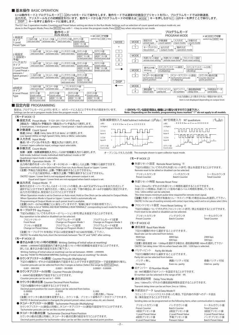
E21は動作モードとプログラムモード 1 - 4 の2つのモードにて操作をします。動作モードでは通常の計数及びプリセットを行い、プログラムモードでは計数速度、出力方式、プリスケールなどの初期設定を行います。動作モードから各プログラムモードの切替えは キーを押しながら 1 - 4 のキーを押すことで移行します。 キーを押すと動作モードに復帰します。
RUN MODE
BASIC OPERATION
PROGRAMMING
Low Speed (30Hz) or High Speed (1kHz, 5kHz or 8kHz ) selectable.
2-level preset, 1-level preset + prewarn, 1-level preset + batch selectable.
Operation Mode
設定は、プログラムモードにより行います。1 - 4のモードに入ることでそれぞれの設定を行います。 ※ 印の付いている設定項目は、機種により異なりますのでご注意下さい。■ 設定内容
低速 (30Hz) ・ 高速 (1kHz, 5kHz または 8kHz )より選択します。
Add mode, Subtract mode, Individual Add/Subtract mode or 90° Quadrature input mode is selectable.
Operation method can be selected from Over run, Auto-Reset, Equal or Upper / Lower.
《NOTE》 Upper / Lower limit is not equipped when prewarn output is set. Equal and Upper / Lower limit are not equipped when batch output is set.
加算 ・ 減算 ・ 加算減算個別入力もしくは90°位相差入力から選択します。
出力時の動作をオーバーラン ・ オートリセット ・ 一致もしくは上限 / 下限から選択できます。
《注意》 予報出力設定時は、上限 / 下限を選択することができません。 バッチ出力設定時は、一致及び上限 / 下限を選択することはできません。
● 動作方式 ※
※Output Mode動作方式がオーバーランもしくはオートリセットの場合、ホールド又はワンショットを出力方式として選択することができます。動作方式が、一致もしくは上限 / 下限の場合は、ホールドが自動的に設定されます。 出力方式の設定は、設定段ごとに行うことができます
《注意》 OUT1 - OUT4は機種ごとに異なっていますので、”配線と端子”の項を参照下さい。
● 出力方式
Key Protect下記の6項目についてそれぞれキーオペレーション許可/禁止を設定することができます。
● キープロテクト
■ 基本操作
MODEDISP
DISP
MODE
2
3
4
動作モード
Count Speed● 計数速度
2段出力 ・ 1段出力+予報出力・1段出力+バッチ出力より選択します。※ E21-201 / E21-211のみ onlyPreset Mode● 設定方式
Count Mode● 計数方式Contact /open collector input, voltage input selectable.接点 / オープンコレクタ入力 ・ 電圧入力より選択します。
Input Mode● 入力方式
※出力段数により表示されない項目があります。Item is not displayed depending on output level.
PROGRAM MODE
Writing書き込み値
counter prescale(multiplying)
カウンタプリスケール(逓倍)counter prescale(dividing)
カウンタプリスケール(分周)
tachometer prescale(multiplying)
タコメータプリスケール(逓倍)counter decimal point position
カウンタ小数点位置tachometer decimal point position
タコメータ小数点位置
key protectキープロテクト
output mode出力方式
operation mode動作方式
preset type設定方式
count speed計数速度
input mode入力方式
count mode計数方式
remote reset setting外部リセット設定
remote reset time外部リセット時間
front reset settingフロントリセット設定
baud rate通信速度
parity bitパリティビット
ID numberIDナンバー
send data外部送出データ
delay time通信遅延時間
プログラムモード
1
+
MODE
1+
MODE
2+
MODE
3+
MODE
4+
MODEは で切替
フロントリセット
プリセット値変更Front Reset
Change on Preset Value
Writing (Setting of initial value at resetting) can be set between -99999 - +999999.See the "HOW TO PROGRAM WRITING (Setting of initial value at resetting)" for details.
Change on Program Mode 1
Change on Program Mode 2
Change on Program Mode 3
Change on Program Mode 4
Remote Reset Setting下記の3項目についてそれぞれ外部リセット許可 / 禁止を設定することができます。
● 外部リセット設定
プログラムモード1変更
プログラムモード2変更
プログラムモード3変更
プログラムモード4変更
プリセットカウンタ バッチカウンタ トータルカウンタ
Front Reset Setting下記の3項目についてそれぞれフロントリセット許可 / 禁止を設定することができます。
● フロントリセット設定
Writing (Setting of initial value at resetting)-99999 - +999999の設定範囲内で書き込み値 (リセット時の初期値)を設定することができます。 詳しくは、書き込み値の設定方法をご覧下さい。
● 書き込み値 (リセット時の初期値)
Counter Prescale (Multiplying)下記の3種類のいずれかの設定範囲内で設定することができます( ENT/UD キーで設定範囲切り替え)。
● カウンタプリスケール(逓倍)
プリセットカウンタ バッチカウンタ トータルカウンタ
0.001 - 999.999 0.0001 - 99.9999 0.00001 - 9.99999
Counter Prescale (Dividing)1 - 9999の設定範囲内で設定することができます。
● カウンタプリスケール(分周)
Counter Decimal Point Position下記の6種類の中から選択することができます。
● カウンタ小数点位置
Remote Reset Time
1ms / 20msのいずれかの外部リセット時間を選択することができます。外部リセット時間は、外部リセット信号の最小パルス時間を意味しています。
● 外部リセット時間
《モード MODE 1》
《モード MODE 2》
Baud Rate Mode下記の5種類の中から選択することができます。
● 通信速度
Delay Time Mode2ms / 100msのいずれかの通信遅延時間を設定することができます。
● 通信遅延時間
ID Number Mode00 - 99の範囲内でIDナンバーを設定することができます。
● IDナンバー
Send Data Modeコミュニケーションリクエストがあった場合、下記内容の外部へのデータ送出有 / 無を設定することができます。
● 外部送出データ
パリティ無し 偶数パリティ付加 奇数パリティ付加
9600 bps1200 bps
No parity Even no. parity Odd no. parity
4800 bps600 bps
2400 bps300 bps
プリセットカウント値
1段目プリセット値
4段目プリセット値
バッチカウント値
2段目プリセット値
予報プリセット値
トータルカウント値
3段目プリセット値
バッチプリセット値
Parity Bit Mode下記の3種類の中から選択することができます。
● パリティビット
《モード MODE 4》
《モード MODE 3》
《注意》 カウンタ小数点位置を変更すると、カウント値、プリセット値等のデータがクリアされます。
0. 000000. 00
0. 00000. 0
0. 000小数点無し / None
Tachometer Prescale (Multiplying)カウンタプリスケール(逓倍)と同様に、タコメータプリスケール(逓倍)の設定を行うことができます。
● タコメータプリスケール(逓倍)
Tachometer Decimal Point Positionカウンタ小数点位置と同様に、タコメータ小数点位置の設定を行うことができます。
● タコメータ小数点位置
《注意》 外部リセット信号が有接点(リレーやスイッチ等) の場合は20msを選択して下さい。《NOTE》 In the case of resetting remotely with contact input (relay, switch and so on), please select 20ms.
Front reset to be abled or disabled can be selected.
Baud rate can be selected from below.
Parity bit can be selected from below.
ID number can be selected in the range of 00 - 99.
Transmit delay time can be set from 2ms or 100ms.
Sending data can be programmed on the following items, when communication is requested.
The example shown is open collector input mode.
Add/Subtract individual ( )
- 9 9 9 9 9 9 9 9 9 9 90
H
H
L
L
01 1 1
2 23
23
( 6 Digits )
Input A
Input B
Count value
90° quadrature ( )- 9 9 9 9 9 9 9 9 9 9 90
H
H
L
L
01 1
2 2 2 23 3 3
( 6桁)
オープンコレクタ入力の例
入力 A
入力 B
カウント値
( 6 Digits )
Input A
Input B
Count value
( 6桁)
入力 A
入力 B
カウント値
加算/減算個別入力 90°位相差入力
※
※
※
The E21 has 2 operation modes. Counting and Preset Values setting are done in the Run Mode. Settings such as selection of count speed and output mode etc. aredone in the Program Mode. Press the MODE key with 1 - 4 key to enter the program mode. Press DISP key when returning to run mode.
Note : Depending on the models, programming items marked "※" do not apply to all models.
When Operation mode is set to Overrun or Auto-reset, Hold or One Shot can be selected in Output Mode.When Operation Mode is Equal or Upper / Lower, Hold is automatically set.Programming of Output Mode on each preset level is available.
《NOTE》 Refer to list of ”WIRING AND REAR TERMINALS-REAR TERMINALS” corresponding to each model for the setting.
Key operation to be abled or disabled can be selected.
Remote reset to be abled or disabled can be selected.
1ms / 20ms either can be selected.This time means minimum pulse time required for remote reset signal.
Preset Counter Batch Counter Total Counter
Preset Counter Batch Counter Total Counter
Preset Counter
1 Level Preset Value
4 Level Preset Value
Batch Counter
2 Level Preset Value
Prewarn Value
Total Counter
3 Level Preset Value
Batch Preset Value
Counter prescale can be selected from the 3 ranges as below (Select the range by ENT/UD key).
Counter prescale can be set to 1 - 9999.
Decimal point position for count values can be selected from below.
Tachometer prescale can be set like counter prescale.
Decimal point position for tachometer value can be set like counter decimal point position.
《NOTE》 If decimal position is changed, the present preset value, count value, etc. are cleared.
《注意》 キープロテクトを有効にするには設定後端子19とGNDを短絡して下さい。《NOTE》 To enable Key lock, short the terminals between "No.19" and "GND" after setting.
Settings can be set in program mode. Enter the program mode 1-4.
switch by key
《注意》 通信速度 300 - 1200bpsを選択する場合は、通信遅延時間 100msを選択して下さい《NOTE》 Set delay time 100 ms when baud rate 300 - 1200 bps is selected.
MODE
DISPは で切替switch by keyDISP
1 Level Preset Type
2 Level Preset (1 Level Preset +prewarn / batch preset )Type
4 Level Preset Type
total count valueトー タルカウント値
tachometer valueタコメータ値
batch count valueバッチカウント値
1st level preset value1段目プリセット値
total count valueトー タルカウント値
tachometer valueタコメータ値
batch count valueバッチカウント値
1 段設定タイプ
2 段設定(1 段設定+予報/バッチ出力)タイプ
4段設定タイプ
count valueカウント値
total count valueトー タルカウント値
tachometer valueタコメータ値
batch count valueバッチカウント値
1st level preset value1段目プリセット値count valueカウント値
2nd level preset value2段目プリセット値count valueカウント値
total count valueトー タルカウント値
tachometer valueタコメータ値
batch count valueバッチカウント値
1st level preset value1段目プリセット値count valueカウント値
prewarn preset value予報プリセット値count valueカウント値
total count valueトー タルカウント値
tachometer valueタコメータ値
batch count valueバッチカウント値
batch preset valueバッチプリセット値
1st level preset value1段目プリセット値count valueカウント値
1st level preset value1段目プリセット値count valueカウント値
2nd level preset value2段目プリセット値count valueカウント値
3rd level preset value3段目プリセット値count valueカウント値
4th level preset value4段目プリセット値count valueカウント値

-- 3 -
)
DISP キーを押して、1段目プリセット値を表示させます。 (SET1ランプ点灯)
桁別キーを押して、プリセット値を変更します。 (下段全桁が表示され変更中の桁が点滅表示になります)1 - 6で対応する桁の数値を変更します。数値は桁別キーを押すことにより右図の通り移動します。
※但し、6は右図のようになっており、-(マイナス)の数値を設定する際には、このキーを使用します。
数値変更後3秒間キー入力が無い場合、又は ENT/UD キーを押すことにより、数値が確定します。 (数値の点滅が終了し、設定は終了となります)
※ 他のプリセット値の設定・変更についても、同様の手順で行って下さい。
● 1段目プリセット値を、現在値100から2500に変更。
(マイナス)
1)
2)
3)
Press DISP key to make the lower display show 1 level preset value. (Indicator "SET 1" turns on.)
Use digit key 1 - 6 to edit preset value. (all digits of the lower display turn on, and the digit to be edited is blinking.)Change preset value key by using digit keys of 1 - 6 and the numerical value is shifted as shown on the right figure by pressing digit key.
As to the 6 key, the numerical value is shifted as shown on the right figure and the final - is used to edit minus (-) preset value.
Edited numerical values are memorized automatically if there is no key operation for 3 seconds.Also, the above values are programmed by pressing ENT/UD key. (The digit stops blinking and this means the programming is completed.)
How to set or change the preset value is all the same in any models.
In case that 1 level preset value is changed from 100 to 2500.
HOW TO PROGRAM PRESET VALUE■ プリセット値の設定方法
HOW TO PROGRAM COUNT START VALUE■ 書き込み値の設定方法
1)
2)
MODE キーを押しながら3を押し、プログラムモード(モード3)の書き込み値変更の項目に移行させます。 (上段に. と表示され、下段に書き込み値が表示されます)
桁別キーを押して、書き込み値を変更します。 (プリセット値の設定と同様に行って下さい)
数値変更後3秒間キー入力が無い場合、又は ENT/UD キーを押した場合に数値が確定します。 (数値の点滅が終了し、設定は終了となります)
※ 動作モード時にリセットをすることにより、書き込み値をプリセットカウント値に書き込むことができます。 (トータルカウント値には書き込み値は反映されません)
● 書き込み値の設定は、プログラムモード(モード3)の中で行います。 The count start value can be edited in PROGRAM MODE 3.
BATCH FUNCTION■ バッチ機能について
E21シリーズには、バッチカウント機能が付いています。
バッチカウント機能により、例えばダース単位や10・20・50・100と必要に応じた単位で、最終段の出力回数をカウントさせることが可能です。
E21-101/ E21-111では、プリセット値に到達するごとに、+1カウントされます。
E21-401/ E21-411では、4段目のプリセット値に到達するごとに、+1カウントされます。
E21-201/ E21-211では、予報出力機能やバッチ出力機能を使用していない場合、2段目のプリセット値に到達するごとに、+1カウントされます。予報出力やバッチ出力を使用している場合、1段目のプリセット値に到達するごとに、+1カウントされます。
またE21-201/ E21-211でバッチ出力機能を使用している場合、バッチカウントが設定したバッチプリセット値に到達するとバッチ出力が出力されます。
●
・
・
・
・
E21 Series have batch function.
In Batch count function, counting the output time such as the unit by the dozen or unit by 10, 20, 50 and 100 is possible.
E21-101 / E21-111 : One count is added when the counts reach the 1-level preset value.
E21-401 / E21-411 : One count is added when the counts reach the 4-level preset value.
E21-201 / E21-211 (Batch preset / Prewarn preset not used) : One count is added when the counts reach the 2-level preset value.E21-201 / E21-211 (Batch preset / Prewarn preset used) : One count is added when the counts reach the 1-level preset value.
E21-201 / E21-211 (Batch preset used) : The batch output turns ON when the batch count reaches the batch preset value.
MOUNTING METHOD■ 取付け方法
パネル厚最大14mmまで可能
Panel thickness : max 14mm
《注意》パネルクランパーを取付けると、その部分は5mm程度ずつ外形寸法が大きくなりますので、並べて取付ける場合、上下左右の間隔には、十分に注意して下さい。パネルクランパーのネジを締めすぎないよう注意して下さい。
パネル前面よりカウンタを挿入し、付属のパネルクランパーの爪をカウンタ側面の穴に掛け、ネジを締めて固定して下さい。Insert the unit from front side of panel, and hang the nails of panel clamper on both sides or upper-lower side of the unit, and fix the unit by fastening the screw.
《NOTE》 The thickness of panel clamper is approx. 5mm.Make enough space to arrange other unit on this panel.Avoid excessive fastening for the screw of panel clamper.
RESET■ リセットについて
Press 3 key while pressing MODE key to enter COUNT SET in PROGRAM MODE 3. (The upper display shows . , and the lower display shows the count start value.)
Edit the count start value by using digit keys. (same as the program of preset value.)
Edited numerical values are memorized automatically if there is no key operation for 3 seconds.Also, the above values are programmed by pressing ENT/UD key. (The digit stops blinking and this means the programming is completed)
The above programmed count start value can be shown on the upper display by pressing front key reset or remote reset on. (Count start value is not reflected on the total count value)
・・・
・・・・・
※
・・・
・・・・・
フロントリセット外部リセット通信を利用したリセット (RESコマンド利用)
プログラムモードでフロント / リモートリセットの許可 / 禁止を設定することができます (通信によるリセットを除く)
通信によるリセットはコマンドにてリセット項目を指定します
どのリセットでもエラー状態 (オーバーフロー・アンダーフロー)からの復帰が可能です
外部リセットでは、リセット信号入力時に計数されません
書き込み値 (リセット時の初期値)は、リセットすることによりプリセットカウント値に書き込まれます (工場出荷時設定 : 0)
トータルカウント値バッチカウント値プリセットカウント値バッチ出力プリセット(予報)出力
Type of reset
Front / Remote reset able or disable can be selected in the PROGRAM MODE. (Except reset by communication)
Reset by communication decides the reset item by command.
Every reset is restorable from error condition (over, under flow).
Does not count during shorting.
The determined writing (setting of initial value at resetting) can be shown on the preset count display by reset ON. (Factory settings : 0)
フロントリセットの動作は表示画面により異なります。The operation of the front reset differs depending on the display screen.
Front resetRemote resetReset by serial communication command
Subject to be reset
Total count valueBatch count valuePreset count valueBatch outputPreset (Prewarn) output
● 表示画面毎のフロントリセット動作 Front reset operation for each count display
バッチカウント値の表示中 Batch count display
トータルカウント値
無効
バッチカウント値
リセット
プリセットカウント値
リセット
バッチ出力
停止
プリセット(予報)出力
停止Total count value
Disabled
Batch count value
Reset
Preset count value
Reset
Batch output
Off
Preset (Prewarn) output
Off
トータルカウント値の表示中 Total count display
トータルカウント値
リセット
バッチカウント値
無効
プリセットカウント値
リセット
バッチ出力
無効
プリセット(予報)出力
停止Total count value
Reset
Batch count value
Disabled
Preset count value
Reset
Batch output
Disabled
Preset (Prewarn) output
Off
プリセットカウント値の表示中 Preset count display
トータルカウント値
無効
バッチカウント値
無効
プリセットカウント値
リセット
バッチ出力
無効
プリセット(予報)出力
停止Total count value
Disabled
Batch count value
Disabled
Preset count value
Reset
Batch output
Disabled
Preset (Prewarn) output
Off
● リセットは、次の3つの方法で行うことができます。
● リセットの対象となるものは、次の通りです。
5 3 1
6 4 2
MODERESET
BATCH
SET4
SET3
SET2
SET1
TACHO OUT 1 OUT 2 OUT 3 OUT 4
DISP ENTUD
SET4
SET3
SET2
SET1
SET4
SET3
SET2
SET1
SET4
SET3
SET2
SET1
1 ~ 5
6
1)
2)
3)

. .(yes) (no)
. .(yes) (no)
. .(yes) (no)
. .(yes) (no)
. .(yes) (no)
. .(yes) (no) (許可) (禁止)
(許可) (禁止)
(許可) (禁止)
(許可) (禁止)
(許可) (禁止)
(許可) (禁止)
- 4 -
Program Item Setting Values Default ValueProgram Item Display
PROGRAM MODE OPERATION (MODE 1) Press and hold MODE + 1 to enter the program mode (MODE 1).Press individual digit setting keys to change setting values. Press DISP key to return to Run Mode.
.
.
.
.
.
-
-
Key 1 will selectthe desired value
Keys 2 - 4 will changedigits
Key 1 will select the desired value
Count Speed
Count Mode
Operation Mode
Key Protect
桁別キーNo.1にて設定項目を変更
Key 1 will selectthe desired value
桁別キーNo.1にて設定項目を変更
Key 1 will selectthe desired value
桁別キーNo.1にて設定項目を変更
Key 1 will selectthe desired value
桁別キーNo.1にて設定項目を変更
Key 1 will selectthe desired value
桁別キーNo.1にて設定項目を変更
Key 1 will selectthe desired value
桁別キーNo.1にて設定項目を変更
Key 1 will selectthe desired value
桁別キーNo.1にて設定項目を変更
桁別キーNo.1にて設定項目を変更
桁別キーNo.2 - 4にて対応桁の数値を変更
Setting Key表示 設定キープログラム項目 設定内容 工場出荷の既定値
計数方式
Output Mode出力方式
動作方式
キープロテクト
計数速度
Preset Type設定方式
Input Type入力方式
■ プログラムモードの操作図 (MODE 1)MODE キー + 1 キーにてプログラムモード(MODE 1)に入ります。設定変更は桁別キーにてセットを行います。 DISPキーを押すと変更を反映して動作モードに戻ります。
"Preset Type" is displayed only for models E21-201 and E21-211.
"設定方式" はE21-201 / E21-211にのみ表示されます 2-level preset .
1-level preset + prewarn. 1-level preset +batch.
2段設定
1段設定+予報設定
1段設定+バッチ設定
接点 / オープンコレクタ入力
電圧入力
加算
減算
加算減算個別
90°位相差
. . . . .
4段 / 2段 / 1段設定
1段設定+予報設定
1段設定+バッチ設定
動作方式が.や . の時のみ表示します
出力方式が .の時のみ表示します
ワンショットの設定範囲は10 - 9990msです
4段設定
2段設定1段設定+予報設定1段設定+バッチ設定
1段設定
. 30 Hz
. 1 kHz. 5 kHz
. 8 kHz
Add
Subtract
Add/Subtract individual
90° quadrature
オーバーラン
オートリセット
一致
上限/下限Over Run
Auto Reset
Equal
Upper / Lower
contact/open collector input .
voltage input .
. . . . .
.
. . .
. .
4-level, 2-level, and 1-level preset
1-level preset + prewarn
1-level preset + batch
4-level preset
2-level preset1-level preset + prewarn1-level preset + batch
1-level preset
Only when "Operation Mode" is .or .
Only when "Operation Mode" is .動作方式が.の時は出力方式の表示はありません動作方式が.や.の時の出力方式はですIf "Operation Mode" is ., "Output Mode" is not displayed.Hold is automatically set when "Operation Mode" is .or ..
Only when "Output Mode" is .
Output Time setting range: 10 - 9990ms
出力方式が.の時のみ表示します
MODE
MODEMODE
DISP
1MODE
MODE
MODE
MODE
+
Front Reset key
Preset value change
Program Mode 1 change
Program Mode 2 change
Program Mode 3 change
Program Mode 4 change
Protect item
フロントリセットキー
プリセット値変更
プログラム MODE 1 変更
プログラム MODE 2 変更
プログラム MODE 3 変更
プログラム MODE 4 変更
プロテクト項目
..
..
ホールド
ワンショット
上限
下限Hold
One Shot
Upper Limit
Lower Limit
.
.
.
.
.
.
.
・ キープロテクトを有効に するには設定後端子19と GNDを短絡して下さい。
《 注意 NOTE 》
To enable key protect after setting, short the terminals "No.19" and "GND".
-- 5 -
Program Item Setting Values Default ValueProgram Item Display
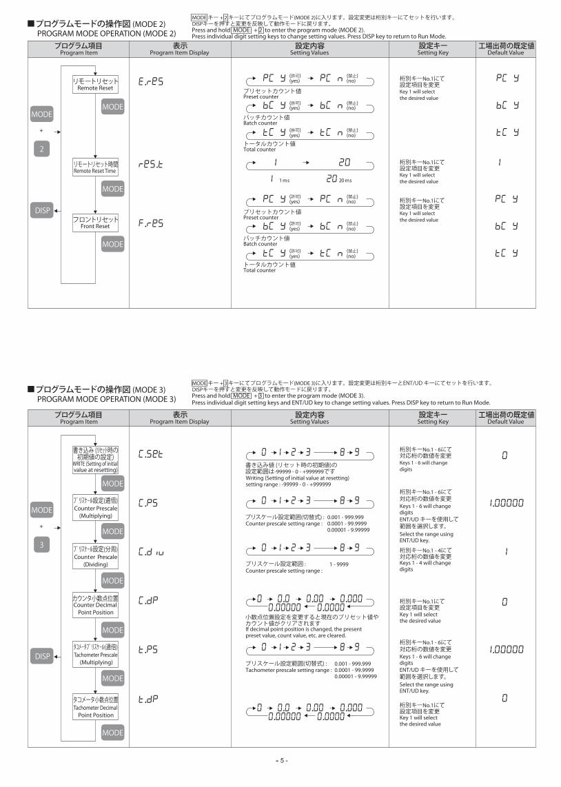
PROGRAM MODE OPERATION (MODE 2) Press and hold MODE + 2 to enter the program mode (MODE 2).Press individual digit setting keys to change setting values. Press DISP key to return to Run Mode.
.
.
.
Key 1 will selectthe desired value
Remote Reset Time
桁別キーNo.1にて設定項目を変更
Key 1 will selectthe desired value
桁別キーNo.1にて設定項目を変更
Key 1 will selectthe desired value
桁別キーNo.1にて設定項目を変更
Key 1 will selectthe desired value
桁別キーNo.1にて設定項目を変更
Key 1 will selectthe desired value
桁別キーNo.1にて設定項目を変更
Setting Key表示 設定キープログラム項目 設定内容 工場出荷の既定値
Program Item Setting Values Default ValueProgram Item Display Setting Key表示 設定キープログラム項目 設定内容 工場出荷の既定値
リモートリセット時間
Remote Resetリモートリセット
Front Resetフロントリセット
プログラムモードの操作図 (MODE 2)MODE キー + 2 キーにてプログラムモード(MODE 2)に入ります。設定変更は桁別キーにてセットを行います。 DISPキーを押すと変更を反映して動作モードに戻ります。
PROGRAM MODE OPERATION (MODE 3) Press and hold MODE + 3 to enter the program mode (MODE 3).Press individual digit setting keys and ENT/UD key to change setting values. Press DISP key to return to Run Mode.
プログラムモードの操作図 (MODE 3)MODE キー + 3 キーにてプログラムモード(MODE 3)に入ります。設定変更は桁別キーとENT/UD キーにてセットを行います。 DISPキーを押すと変更を反映して動作モードに戻ります。
MODE
MODE
MODE
DISP
2
MODE
+
プリスケール設定(逓倍)
WRITE (Setting of initial value at resetting)
書き込み (リセット時の初期値の設定)
MODE
MODE
MODE
DISP
3
+
プリセットカウント値 Preset counter
バッチカウント値 Batch counter
トータルカウント値 Total counter
1 ms 20 ms
(yes) (許可) (禁止)
(許可) (禁止)
(許可) (禁止)
(許可) (禁止)
(許可) (禁止)
(許可) (禁止)
(no)
.
. .
(yes) (no)
(yes) (no)
プリセットカウント値 Preset counter
バッチカウント値 Batch counter
トータルカウント値 Total counter
(yes) (no)
(yes) (no)
(yes) (no)
Writing (Setting of initial value at resetting) setting range : -99999 - 0 - +999999
Keys 1 - 6 will changedigits
桁別キーNo.1 - 6にて対応桁の数値を変更
Keys 1 - 4 will changedigits
桁別キーNo.1 - 4にて対応桁の数値を変更
書き込み値 (リセット時の初期値)の設定範囲は-99999 - 0 - +999999です
Counter Prescale(Multiplying)
プリスケール設定(分周)
MODE
.
Counter Prescale(Dividing)
0.001 - 999.999Counter prescale setting range : 0.0001 - 99.9999 0.00001 - 9.99999
1 - 9999Counter prescale setting range :
プリスケール設定範囲(切替式) :
プリスケール設定範囲 :
小数点位置設定を変更すると現在のプリセット値やカウント値がクリアされます
タコメータプリスケール(逓倍)
Counter Decimal Point Position
カウンタ小数点位置
MODE
MODE
.
. .
. . ...
Keys 1 - 6 will changedigits
桁別キーNo.1 - 6にて対応桁の数値を変更
ENT/UD キーを使用して範囲を選択します。
. . ...
Tachometer Prescale (Multiplying)
タコメータ小数点位置
MODE
.
Tachometer Decimal Point Position
0.001 - 999.999Tachometer prescale setting range : 0.0001 - 99.9999 0.00001 - 9.99999
Select the range using ENT/UD key.
Keys 1 - 6 will changedigits
桁別キーNo.1 - 6にて対応桁の数値を変更
ENT/UD キーを使用して範囲を選択します。Select the range using ENT/UD key.
プリスケール設定範囲(切替式) :
If decimal point position is changed, the present preset value, count value, etc. are cleared.
- 6 -
Program Item Setting Values Default ValueProgram Item Display
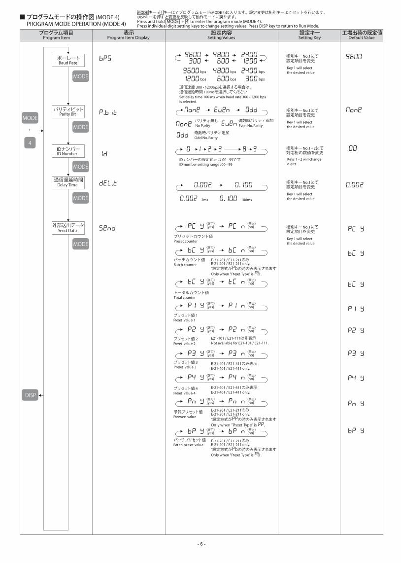
PROGRAM MODE OPERATION (MODE 4) Press and hold MODE + 4 to enter the program mode (MODE 4).Press individual digit setting keys to change setting values. Press DISP key to return to Run Mode.
.
.
Key 1 will selectthe desired value
Parity Bit
Delay Time
Send Data
桁別キーNo.1にて設定項目を変更
Key 1 will selectthe desired value
桁別キーNo.1にて設定項目を変更
Key 1 will selectthe desired value
桁別キーNo.1にて設定項目を変更
Key 1 will selectthe desired value
桁別キーNo.1にて設定項目を変更
Keys 1 - 2 will changedigits
桁別キーNo.1 - 2にて対応桁の数値を変更
Setting Key表示 設定キープログラム項目 設定内容 工場出荷の既定値
通信遅延時間
外部送出データ
パリティビット
Baud Rateボーレート
ID NumberIDナンバー
■ プログラムモードの操作図 (MODE 4)MODE キー + 4 キーにてプログラムモード(MODE 4)に入ります。設定変更は桁別キーにてセットを行います。 DISPキーを押すと変更を反映して動作モードに戻ります。
bps bps bps
bps bps
. . .
. 2ms . 100ms
bpsMODE
MODE
MODE
DISP
4
MODE
MODE
MODE
+No Parity Even No. Parityパリティ無し 偶数時パリティ追加
Odd No. Parity奇数時パリティ追加
ID number setting range : 00 - 99IDナンバーの設定範囲は 00 - 99です
プリセットカウント値 Preset counter
バッチカウント値 Batch counter
トータルカウント値 Total counter
(yes) (no)
(yes) (no)
(yes) (no)
プリセット値 1 Preset value 1
プリセット値 2Preset value 2
プリセット値 3Preset value 3
Not available for E21-101 / E21-111.E21-101 / E21-111は非表示
E-21-401 / E21-411 only.E-21-401 / E21-411のみ表示
E-21-401 / E21-411 only.E-21-401 / E21-411のみ表示
(yes) (no)
(yes) (no)
(yes) (no)
プリセット値 4 Preset value 4
予報プリセット値Prewarn value
バッチプリセット値Batch preset value
E-21-201 / E21-211 only.E-21-201 / E21-211のみ
Only when "Preset Type" is ."設定方式がの時のみ表示されます
E-21-201 / E21-211 only.E-21-201 / E21-211のみ
Only when "Preset Type" is .
"設定方式がの時のみ表示されます
E-21-201 / E21-211 only.E-21-201 / E21-211のみ
Only when "Preset Type" is .
"設定方式がの時のみ表示されます
(yes) (no)
(yes) (no)
(yes) (no)
(許可) (禁止)
(許可) (禁止)
(許可) (禁止)
(許可) (禁止)
(許可) (禁止)
(許可) (禁止)
(許可) (禁止)
(許可) (禁止)
(許可) (禁止)
通信速度 300 - 1200bpsを選択する場合は、通信遅延時間 100msを選択してくださいSet delay time 100 ms when baud rate 300 - 1200 bps is selected.

-- 7 -
WIRING AND REAR TERMINALS■ 配線と端子
REAR TERMINALS
POWER SOURCE
OUTPUT
RESET
KEY PROTECT
GND
17 19
To reset remotely, short terminals "No.18" and "GND" with a relay, microswitch, etc. (The unit does not count while shorted)
Refer to the REAR TERMINALS and the LIST FOR OUTPUT TERMINALS.
端 子 配 列
電 源
リセット
INPUT
入 力
出 力
キープロテクト
SERIAL COMMUNICATION
(RS-485)
シリアルコミュニケーション
COMMUNICATION REQUEST(RS-485)
コミュニケーションリクエスト
オープンコレクタ入力タイプ
接点入力 オープンコレクタ入力
電圧入力タイプ
加算
IN A IN B GND
171615 171615
加算
減算
Open collector Input Type
Voltage Input Type
Contact Input Open collector Input
add
減算sub
IN A IN B GND
add
sub
端子18とGNDをマイクロスイッチやリレーで短絡させることによりカウント値及び出力をリセットできます。(短絡中はカウントされません)
端子配列図及び出力端子一覧表をご参照下さい。
By shorting terminals "No.19" and "GND", programming or editing selected items in KEY PROTECT MODE is invalid.
端子19とGNDを短絡させることにより、プログラムモードで指定したオペレーション禁止が有効となります。
端子27とGNDを短絡することにより、簡単にデータの呼び出しを行うことができます。
<リレー出力タイプ>
<オープンコレクタ トランジスタ出力タイプ>
Supply 100 - 240VAC to terminals "No.22" & "No.23".端子22と23に AC100 - 240Vを入れてください。22 23
∼
GND
27 28GND
27 28
GND
18 17GND
17 18
EXTERNAL POWER SUPPLY
外部電源供給 端子21より、外部供給電源を取り出すことができます。(DC12V ±10% 100mA max.)21
通信(シリアルコミュニケーション)をご利用の際は、端子25・26をご使用下さい。
※ 通信機器間のGNDを接続して下さい。Connect "GND" of communication devices.
25 26
接点入力 電圧入力
加算
IN A IN B 12V
211615 171615
加算
減算
Contact Input Voltage Input
add
add
sub減算sub
IN A IN B GND
COM.N.C. N.O.
AC
COM.N.C. N.O.E- C E- C
COM.N.C. N.O. COM.N.C. N.O.E- C E- C
OUT1 OUT2
OUT3 OUT4
1 2 3 4 5 6 7
8 9 10 11 12 13 14
15 16 17 18 19 20 21
22 23 24 25 26 27 28
IN A IN B 12VGND
+ - REQ
RESET KEY/P GND
GNDAC100-240V RS-485
≪注意≫・ 配線作業をする場合は、電源を切った状態で行って下さい。・ 結線終了後、ネジの緩みや誤配線がないことを確認して下さい。・ ネジの締付けの際には、過度の締付けをしないよう注意して下さい。・ 未使用の端子は、中継端子として使用しないで下さい。
≪NOTE≫Be sure to turn the power supply off in case of doing the wiring.Confirm the looseness of screw, wrong wiring.. etc., after wiring.Avoid the excessive fastening for terminal of the unit.Do not use the blank terminal as relay terminal.
・・・・
※ OUT1-4は機種により異なりますので、下の出力端子一覧表をご参照下さい。
形式 MODELE21-101 / E21-111E21-201 / E21-211E21-201 / E21-211E21-201 / E21-211E21-401 / E21-411
OUT1OUTOUT1OUTOUTOUT1
OUT2-OUT2PREWARNBATCHOUT2
OUT3----OUT3
OUT4----OUT4
※入力方式がUP(加算)又はDO(減算)の時は、IN Aが有効になりIN Bは無効となります
入力方式 Input ModeUPDOUP DOQUAD
ADDSUBADD SUB
IN A加算減算加算90°位相差 90° QUAD
IN B--減算
Terminal "No.21" is used as the sensor power source. (12VDC ±10% 100mA max.)
By shorting terminals "No.27" and "GND", it will be available to read the data easily.
Use the terminal "No.25" and "No.26" in case communication is required.
In case input mode is UP(add) or DO(sub.), IN A is valid, but IN B is invalid.
<RELAY OUTPUT TYPE>
<OPEN COLLECTOR TRANSISTOR OUTPUT TYPE>
(- : 未使用端子)(- : NOT AVAILABLE)
OUT1 - 4 are different according to each models.Refer to the LIST FOR OUTPUT TERMINALS shown in below table.
+ -
LIST FOR OUTPUT TERMINALS出力端子一覧表
オープンコレクタ入力Open collector Input
オープンコレクタ入力Open collector Input
オープンコレクタ入力Open collector Input
- 8 -
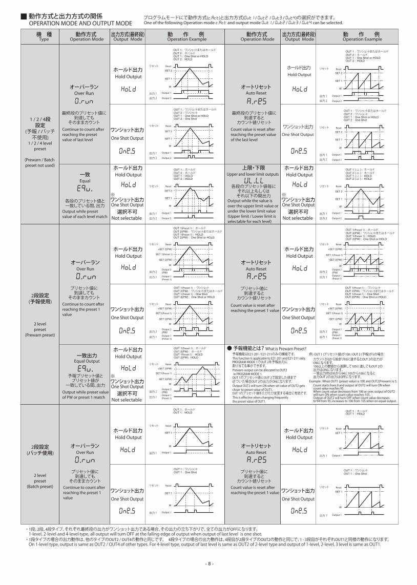
OPERATION MODE AND OUTPUT MODE One of the following Operation mode . and output mode / / / can be selected.プログラムモードにて動作方式(.)と出力方式( / / / )の選択ができます。動作方式と出力方式の関係
・ 1段、2段、4段タイプ、それぞれ最終段の出力がワンショット出力である場合、その出力の立ち下がりで、全ての出力がOFFになります。
・ 1段タイプの場合の出力動作は、他のタイプのOUT2 / OUT4の動作と同じです。 4段タイプの場合の出力動作は、4段目が2段タイプのOUT2の動作と同じで、1 - 3段目がそれぞれOUT1と同様の動作になります。
Type Operation Mode Output Mode Operation Example
1 / 2 / 4 levelpreset
(Prewarn / Batch preset not used)
Over Run
Hold Output
Reset
Output 1
Output 2
SET 2
SET 1
W
One Shot Output
Reset
Output 1
Output 2
SET 2
SET 1
W
動作方式機 種 出力方式(最終段) 動 作 例Operation Mode Output Mode Operation Example動作方式 出力方式(最終段) 動 作 例
ホールド出力
Hold Outputホールド出力
ワンショット出力
Hold Output
One Shot Output
ホールド出力
ワンショット出力
Hold Output
One Shot Output
ホールド出力
ワンショット出力
Hold Output
One Shot Output
ホールド出力
ワンショット出力
Hold Output
One Shot Output
ホールド出力
ワンショット出力
Hold Output
One Shot Output
ホールド出力
ワンショット出力
Not selectable
ワンショット出力
選択不可
1 / 2 / 4段設定
(予報 / バッチ不使用)
One Shot Output
Hold Outputホールド出力
Not selectable
ワンショット出力
選択不可
※
※ ※
One Shot Output
Hold Outputホールド出力
Not selectable
ワンショット出力
選択不可One Shot Output
2 levelpreset
(Prewarn preset)
What is Prewarn Preset?
2段設定(予報使用)
● 予報機能とは?
2 levelpreset
(Batch preset)
2段設定(バッチ使用)
出力 1
出力 2
リセット
Reset
Output 1
Output 2
SET 2
SET 1
W
出力 1
出力 2
リセット
Reset
Output 1
Output 2
SET 2
SET 1
W
出力 1
出力 2
リセット
出力 1
出力 2
リセット
オーバーラン
.
Equal一致
.
Upper and lower limit outputs上限・下限
.
OUT 1 : One Shot or HOLDOUT 2 : HOLD
OUT 1 : ワンショットまたはホールドOUT 2 : ホールド
OUT 1 : One Shot or HOLDOUT 2 : One Shot
OUT 1 : ワンショットまたはホールドOUT 2 : ワンショット
OUT 1 : HOLDOUT 2 : HOLD
OUT 1 : ホールドOUT 2 : ホールド
Reset
Output 1
Output 2
SET 2
SET 1
W
出力 1
出力 2
リセット
OUT 1 ( ) : HOLDOUT 2 ( ) : HOLD
OUT 1 ( ) : ホールドOUT 2 ( ) : ホールド
OUT 1 : One Shot or HOLDOUT 2 : HOLD
OUT 1 : ワンショットまたはホールドOUT 2 : ホールド
Reset
Output 1
Output 2
SET 2
SET 1
W
出力 1
出力 2
リセット
OUT 1 : One Shot or HOLDOUT 2 : One Shot
OUT 1 : ワンショットまたはホールドOUT 2 : ワンショット
Over Run
Reset
Output 2(PW)Output 1(Preset 1)
SET1(Preset 1)
W
出力 2
出力 1
リセット
Reset
Output 2(PW)Output 1(Preset 1)
SET 1(Preset 1)
-SET 2(PW)
+SET 2(PW)
-SET 2(PW)
+SET 2(PW)
Reset
Output 2(PW)Output 1(Preset 1)
SET1(Preset 1)
W
出力 2
出力 1
リセット
-SET 2(PW)
+SET 2(PW)
W
出力 2
出力 1
リセット Reset
Output 2(PW)Output 1 (Preset 1)
SET 1(Preset 1)
-SET 2(PW)
+SET 2(PW)
W
出力 2
出力 1
リセット
オーバーラン
.Auto Resetオートリセット
.
Equal Output一致出力
.
OUT 1(Preset 1) : HOLDOUT 2(PW) : One Shot or HOLD
OUT 1(Preset 1) : ホールドOUT 2(PW) : ワンショットまたはホールド
OUT 1(Preset 1) : One ShotOUT 2(PW) : One Shot or HOLD
OUT 1(Preset 1) : ワンショットOUT 2(PW) : ワンショットまたはホールド
OUT 1Preset 1) : HOLDOUT 2(PW): HOLD
OUT 1(Preset 1) : ホールドOUT 2(PW) : ホールド
OUT 1(Preset 1) : HOLDOUT 2(PW) : One Shot or HOLD
OUT 1(Preset 1) : ホールドOUT 2(PW) : ワンショットまたはホールド
Reset
Output 1
SET 1
W
Reset
Output 1
SET 1
W
出力 1
リセット
Reset
Output 1
SET 1
W
出力 1
リセット
出力 1
リセット
OUT 1 : HOLDOUT 1 : ホールド
OUT 1 : One ShotOUT 1 : ワンショット
OUT 1 : HOLDOUT 1 : ホールド
Reset
Output 1
SET 1
W
出力 1
リセット
OUT 1 : One ShotOUT 1 : ワンショット
最終段のプリセット値に到達しても
そのままカウント
各段のプリセット値と一致している間、出力
各段のプリセット値毎にそれ以上もしくはそれ以下の間出力
プリセット値に到達しても
そのままカウント
Over Runオーバーラン
.プリセット値に到達しても
そのままカウント
予報プリセット値とプリセット値が
一致している間、出力
プリセット値に到達すると
カウント値リセット
Auto Resetオートリセット
. プリセット値に到達すると
カウント値リセット
Auto Resetオートリセット
. 最終段のプリセット値に
到達するとカウント値リセット
Reset
Output 2(PW)Output 1(Preset 1)
SET 1(Preset 1)
W
出力 2
出力 1
リセット
-SET 2(PW)
+SET 2(PW)
OUT 1(Preset 1) : One ShotOUT 2(PW) : One Shot or HOLD
OUT 1(Preset 1) : ワンショットOUT 2(PW) : ワンショットまたはホールド
予報機能はE21-201 / E21-211のみの機能です。
PROGRAM MODE 1でOUT 2を予報出力に割り当てる事ができます。
OUT 1のプリセット値にOUT 2で設定した値まで近づいた場合OUT 2の出力がONになります。
OUT 1のプリセット値をたびたび変更する場合に有効です。
. .
. .
. .
1-level, 2-level and 4-level type, all output will turn OFF at the falling edge of output when output of last level is one shot.
On 1-level type, output is same as OUT2 / OUT4 of other types. For 4-level type, output of last level is same as OUT2 of 2-level type and output of 1-level, 2-level, 3 level is same as OUT1.
Continue to count after reaching the preset value of last level
Count value is reset after reaching the preset value of the last level
Output while the value is over the upper limit value or under the lower limit value(Upper limit / Lower limit isselectable for each level)
Count value is reset after reaching the preset 1 value
Count value is reset after reaching the preset 1 value
Continue to count after reaching the preset 1 value
Continue to count after reaching the preset 1 value
Output while preset value of each level match
Output while preset value of PW or preset 1 match
This function is applicable to E21-201 and E21-211 only.
Prewarn output can be allocated to OUT2 in PROGRAM MODE 1.
Output OUT2 will turn ON when set value of OUT2 gets closer to preset value of OUT1.
This is effective when changing frequently the preset value of OUT1.
例 : OUT 1 (プリセット値)が100 / OUT 2 (予報)が5の場合
Example : When OUT1 (preset value) is 100 and OUT2(Prewarn) is 5.Count starts from 0 and output of OUT2 will turn ON when count value reaches 95.When count value decreases from 106 or over, output of OUT2 will turn ON when count value reaches 105.Output of OUT2 will turn OFF when count value decreases to 94 from 95, increases to 106 from 105 when on equal output.
カウントが0から始まり95に達するとOUT 2の出力がONになります。106以上の数値から減算して105に達してもOUT 2の出力はONになります。一致出力時は95から94に105から106になると出力OUT 2の出力はOFFになります。

-- 9 -
SERIAL COMMUNICATION■ シリアルコミュニケーション
● 通信は、RS-485シリアルインターフェースと以下に示す手順、及びASCIIコードにて行います。
● RS-485の2本のデータバス(及びコモン線)により、ホストコンピュータと複数のカウンタ間でデータの送受信が行えます。
● 接続するカウンタは、ユーザーが設定した個別のIDナンバー(ID#)を持っており、コンピュータ1台に対して最大32台のE21シリーズプリセットカウンタを接続することができます。
RDD : カウント値・プリセット値呼び出し(窓枠表示のみ)
RDU : カウント値・プリセット値呼び出し(小数点以下の数値)
RES : カウント値リセット及びオーバー(アンダー)フローエラー状態リセット
STP : カウント禁止
LTD : カウント値・プリセット値のデータ保持
RDI : カウント値・プリセット値呼び出し(整数部の数値)
WRD : プリセット値書き込み
RDO : 出力状態呼び出し
RSM : カウント禁止解除
RLD : LTDコマンドで保持したデータの呼び出し
・ カウント入力パルスが最高計数速度を越えると、通信できなくなることがありますのでご注意下さい。
・ 通信では全て大文字のキャラクタを使用して下さい。(小文字のキャラクタには対応していません。)
《 注意 NOTE 》
① スタートキャラクタ(ASCII62)の意味です。これは全ての通信時に必要です。
② 10進数による2桁のユニットナンバー(ID#)です。全ての通信時に必要です。 (ID#=10(10進数)はID#=0A(16進数)と同意)
③ RDD(カウント値呼び出し)コマンドです。全てのコマンドは3文字から成ります。
④ 通信コマンドの詳細を決める命令(サブコマンド)です。 PCでプリセットカウント値の呼び出しを意味します。
● 一般的な送信フォーマットを下記に示します。(スペースは文章内容を明確にするために入れているだけで、通信時には入れません。)
1 0 R D D P C49 + 48 + 82 + 68 + 68 + 80 + 67 =462(10進数) =1CE(16進数)
⑤ チェックサムです。チェックサムは[ID#]、[通信コマンド]、[通信コマンド詳細]のASCIIコード 値を合計した値(16進数)の下位2桁となります。
チェックサムの計算式
16進の下位2桁(CE)をチェックサムとします。 スタートキャラクタ(>)とキャリッジリターン(cr)は、計算に入れません。
⑥ ASCIIコード(10進数で13)でキャリッジリターンの意味です。全ての通信の最後に必要です。
> 10 RDD PC CE (cr)> ID# コマンド(数値パラメータ) チェックサム(cr) 例 : ユニットナンバー(ID#)10のカウント値を呼び出す場合、 次のようなコードをコンピュータより出力します。① ② ③ ④ ⑤ ⑥ ① ② ③ ④ ⑤ ⑥
TRANSMISSION FORMAT◆ 送信フォーマット
Checksum is the last two significant digits of total sum of hexadecimal of ASCII code of[ID#], [Sub command], [Sub command details]
Check sum is the last two digit of hexadecimal.The (>) start character and carriage return (cr) are not used in calculation.
ASCII carriage return (13 decimal). Required at the end of all commands.
The general command is shown below (Spaces are used for clarity only and must not be transmitted).
COMMAND (numerical data) CHECKSUM
Example : To cause the unit #10 to transmit the value of main counter, send the RDD command as follows.
Message start character (ASCII 62).Required for all transmission to the control.
Two digits serial port ID# in decimal.Required for all transmission to the control.Unit ID#10 (decimal) is unit ID#0A (hexadecimal), capital letters must be used.
RDD command. All serial commands consist of three characters.
Sub command decides the details for serial command.This command means the read of preset count value by PC.
CHECK SUM CALCULATION
(Dec.)(Hex.)
The control uses ASCII code with the RS-485 serial specification.
This allows bi-directional communications and addressing of multiple controls on a single two-wire communication bus.
Each unit is individually addressed via a user programmable ID number. Up to 32 E21 counters can be connected directly to the bus.
Read count value / preset value. (display only)
Read count value / preset value. (value of under decimal point)
Reset for count value and condition of over / under flow error.
Count prohibition.
Store count value / preset value in memory of counter.
There are cases that communication is not possible if the count input pulse speed goes over the max. count speed.
Use only the character of capital letter in communication.
Read count value / preset value. (value of integral number)
Write preset value.
Read output condition.
Cancellation for count prohibition.
Read stored data by LTD command.
通信方式
フォーマット
ボーレート
パリティ
半二重、調歩同期式
ASCIIコード / スタートビット : 1ビット, データビット : 8ビット, パリティビット : 1ビット, ストップビット : 1ビット
300 / 600 / 1200 / 2400 / 4800 / 9600 bps (選択指定)
パリティ無し / 奇数 / 偶数(選択指定)
RS-485 SERIAL INTERFACE◆ RS-485シリアルインターフェース
WAY OF COMMUNICATION
FORMAT
BAUD RATE
PARITY
Half duplex, Asynchronous
ASCII code / Start bit : 1 bit, Data bit : 8 bit (Parity bit : 1 bit), Stop bit : 1 bit
300 / 600 / 1200 / 2400 / 4800 / 9600 bps (Selection)
NON / ODD / EVEN (Selection)
OPERATION MODE AND OUTPUT MODE動作方式と出力方式の関係
● バッチ出力について
例 : 動作方式がオートリセットの場合
リセット
バッチカウンタ 0 1 2 3 4 5 0 1
1段目プリセット値
W
Reset
Batch Counter
1-Level preset
E21 シリーズには、全機種バッチカウント機能が付いています。最終段がプリセット値に到達した時に、バッチカウンタが+1されます。DISP キーによる切り替えでバッチカウント値を確認できます。またE21-201 / E21-211はOUT2をバッチプリセット出力に割り当てることができます。バッチプリセット出力を使用している場合は、バッチカウンタがバッチプリセット値に到達するとバッチ出力がONになります。バッチ出力は、ワンショット又はホールドを選択することができます。E21 Series has Batch count function.Batch counter counts 1 when the preset counter reaches the last level preset value.Batch count value can be displayed by pressing DISP key. On E21-201/E21-211, batch preset output can be allotted to OUT2.The batch output turns on when the batch count reaches the batch preset value.For the batch output, ONE SHOT or HOLD can be selected.
Example : OPERATION MODE is set to AUTO-RESET.
2 levelpreset
(Batch preset)
2段設定(バッチ使用)
※ 通信速度 300 - 1200bpsを選択する場合は、通信遅延時間 100msを選択してくださいSet delay time 100 ms when baud rate 300 - 1200 bps is selected.
※

- 10 -
① ② ③ ④
● 応答承認フォーマット
2本の通信線に並列接続された個々のカウンタは、自分のID#と送信ID#が一致しない場合コマンドには応答しません。ID#が一致した場合は、コマンドとチェックサムは有効となりコマンドを実行します。応答承認フォーマットは下記のようになります。
● エラー応答フォーマット
IDナンバーが一致したにも関わらず、コマンドが無効又は実行できない場合は、カウンタは“N”(未承認)とこれに続く下記のエラーコード及び(cr)を送信し、コマンドは無視します。
※エラーコード一覧
N02 : チェックサムエラー 受信したチェックサムがカウンタのチェックサム計算値と一致しない為、通信エラーと判断します。
N05 : 無効データ 桁数が不的確な数、又は不適当なキャラクタをデータフィールド内で受信した時、エラーになります。
N11 : プリセット値変更中 プリセット値をフロントキーで変更している間は、エラーになります。
N13 : プログラムモード中 プログラムモード中は、エラーになります。
NFF : カウント値がオーバーフロー又はアンダーフロー中 オーバーフローエラー表示、又はアンダーエラー表示中は通信が行えません。
※ 例外として、エラー解除の為のRESコマンドのみ通信可。
例1 : N05 (cr) = 無効データ
RESPONSE FORMAT◆ 応答フォーマット
[A] [データ][チェックサム] (cr)
① 承認キャラクタで、何らかの有効コマンドを受信し実行した時に送信されます。
② 要求されたデータの返答を送信します。
③ カウント値・プリセット値呼び出しコマンド(RDD, RDI, RDU)の時だけ送信します。 [データ]の全キャラクタ(スペースも含む)のASCIIコード値を加算した合計 (16進数)の下位2桁の数字が、チェックサムとなります。
④ ASCIIコードのキャリッジリターンの意味です(10進数で13)。 全ての応答の最後に通信します。
例1 : A (cr) =コマンドの承認を応答(データの要求は無いコマンドの時)例2 : A PC 123456 48 (cr) =カウント値要求の時
Ex1 : N05 (cr) = Invalid data
OVERFLOW or UNDERFLOW FOR COUNT VALUEIt is impossible to communicate under displaying of overflow error or underflow error.
It is possible to communicate by reset command for error cancellation as the exception.
PROGRAM MODE IS ACTIVECannot enter serial program mode if in the program mode.
PRESET VALUE EDIT IN PROGRESSSerial preset cannot be sent if the preset is being changed with the front key.
INVALID DATAIncorrect number of digit or illegal characters received in data field.
CHECKSUM ERRORReceived checksum does not match the calculated check sum.
Ex1 : A (cr) = No data requested.Ex2 : A PC 123456 48 (cr) = Count data requested.
(cr) is the ASCII carriage return (13 decimal). Transmitted at the end of all responses.
[CHECK SUM] is sent only when data is requested (RDD, RDI or RDU commands).The checksum is calculated by adding the ASCII values of all preceding characters (including the spaces).The checksum is the two least significant digits of this sum in hexadecimal.
[DATA] is sent in response to requested data.
[A] is the acknowledge character sent when any valid command is received and executed.
The counter does not respond to a command unless the transmitted ID number matches its programmed ID number.If the ID number match and the command and checksum are valid, the control executes the command and transmits a response as shown below.
If the ID numbers match but the command is not valid or cannot be executed, the counter ignores the command and responds by sending an ASCII "N" (not acknowledged), followed by one character and carriage return.
RESPONSE RECOGNITION FORMAT ERROR RESPONSE FORMAT
[DATA] [CHECK SUM]
* ERROR CODE
通信サブコマンド(XX)
PCBCTCTMP1P2P3P4PWBPSO
要求内容
プリセットカウント値バッチカウント値トータルカウント値タコメータ値1段目プリセット値2段目プリセット値3段目プリセット値4段目プリセット値予報プリセット値バッチプリセット値プログラムモード(外部送出データ)で設定したものを出力
※通信サブコマンドは、機種により異なります。
Communication sub command. (XX)
Communication sub command is different according to each models
※通信サブコマンドは、機種により異なります。Communication sub command is different according to each models
※通信サブコマンドは、機種により異なります。Communication sub command is different according to each models
Contents of command
Preset count valueBatch count valueTotal count valueTachometer value1 level preset value2 level preset value3 level preset value4 level preset valuePrewarn valueBatch preset value
通信サブコマンド(XX)
PCBCTCER
要求内容
プリセットカウント値バッチカウント値トータルカウント値エラー状態(オーバー・アンダーフロー)解除
Communication sub command. (XX)Contents of command
Preset count valueBatch count valueTotal count value
Cancelling for error condition (over, under flow)
通信サブコマンド(XX)
P1P2P3P4PWBP
要求内容
1段目プリセット値2段目プリセット値3段目プリセット値4段目プリセット値予報プリセット値バッチプリセット値
Communication sub command. (XX)Contents of command
1 level preset value2 level preset value3 level preset value4 level preset valuePrewarn valueBatch preset value
通信サブコマンド(XX)
PCTCTM
要求内容
プリセットカウント値トータルカウント値タコメータ値
Communication sub command. (XX)Contents of command
Preset count valueTotal count valueTachometer value
Items selected for SEND DATA in the PROGRAM MODE
● このコマンドはRDDコマンドと同様に使用しますが、サブコマンド(XX)が3種類のみとなります。
● RDIは、カウント値もしくはタコメータ値の整数部分のみを呼び出すコマンドです。
● RDUは、カウント値もしくはタコメータ値の小数点以下のみを呼び出すコマンドです。
2. RDI (XX) : カウント値・タコメータ値呼び出し (整数部の数値)
3. RDU (XX) : カウント値・タコメータ値呼び出し (小数点以下の数値)
送信例 : > 10 RDU PC DF (cr) = ユニットナンバー10のプリセットカウント値呼び出し
応答例1 : A PC.12000000 64 (cr) = プリセットカウント値(小数点以下).12
● このコマンドは、2文字のサブコマンド(XX)を伴います。サブコマンドは、書き込みを行いたいデータ内容により決まります。
● 応答は[A](cr)のみとなります。
● WRDコマンドでは、小数点位置の指定は行えません。小数点は、プログラムモードで指定された位置に表示されます。
4. WRD (XX) : プリセット値書き込み
送信例 : > 10 WRD P1 001234 F9 (cr) = ユニットナンバー10の1段目プリセット値書き込み
● このコマンドは、2文字のサブコマンド(XX)を伴います。サブコマンドは、リセットを行いたいデータ内容により決まります。
● 応答は[A](cr)のみとなります。
● リセットキー、又は外部リセット入力と同様の働きをします。
5. RES (XX) : カウント値リセット
送信例 : > 00 RES PC DD (cr) = ユニットナンバー00のプリセットカウント値をリセット
● このコマンドは、2文字のサブコマンド(XX)を伴います。サブコマンドは、要求するデータ内容により決まります。
1. RDD (XX) : カウント値・プリセット値呼び出し (窓枠表示のみ)
● 応答は[A][サブコマンド][データ][チェックサム](cr)と続きます。
● この応答には、小数点位置もカウンタの表示と同様に示されます。接続することができます。
● 不要なゼロは、スペースと同じ扱いで送信されます。
送信例 : > 01 RDD PC CE (cr) = ユニットナンバー01のプリセットカウント値呼び出し
応答例 : A PC - 123.45 4D (cr) = プリセットカウント値 - 123.45
This requires sub command with two (2) figures (XX). In accordance with required data, sub command is decided.
The response is shown as [sub command] [data] [check sum] [cr] in order.
The decimal point positioning is also shown the same as the display of counter in this response.
Unnecessary zeros [0] are read as a space.
1. RDD (XX) : Reading Count value / Preset value
4. WRD (XX) : Set the preset value.
Example for read : > 01 RDD PC CE (cr) = Read preset count value in unit No. 01.
Example for answer : A PC - 123.45 4D (cr) = preset count value -123.45.
2. RDI (XX) : Read Count value / Tachometer value (the value of integral)
3. RDU (XX) : Read Count value / Tachometer value (the value of under decimal point)
This command works the same as RDD command. Only 3 kinds of sub command as shown below are available.
RDI is the command to read the value of integral part in count value or tachometer value.
RDU is the command to read the value under the decimal point in count value or tachometer value.
This requires sub command with 2 (two) figures (XX). In accordance with the contents of command, sub command is decided as shown below.
The response is [A] (cr) only.
The decimal point position can not be set by WRD command. The decimal point is shown at the position set by the program mode.
This requires sub command with two (2) figures (XX).In accordance with the contents of command, the sub command is decided as shown below.
The response are [A] (cr) only.
This command works same as front reset key operation or reset input.
Example for send : > 10 RDU PC DF (cr) = Read the preset count value in unit No. 10.
Example for response : A PC.12000000 64 (cr) = Preset count value (under the decimal point) : 12.
Example for send : > 10 WRD P1 001234 F9 (cr) = set 1 level preset value in the unit No. (ID No.) 10.
Example for send: > 00 RES PC DD (cr) = Reset preset count value in unit No. (ID No.) 00.
5. RES (XX) : Reset
EXPLANATION FOR COMMUNICATION COMMAND◆ 通信コマンド説明

-- 11 -
EASY COMMUNICATION (COMMUNICATION REQUEST)◆ 簡易通信方法(コミュニケーションリクエスト)
● 簡易的に通信を行う方法として、コミュニケーションリクエスト機能を使用する方法があります。
● これは、コミュニケーションリクエスト端子27とGNDを短絡することにより、プログラムモード(外部送出データ)で設定されているデータを呼び出す機能です。
例 : プログラムモード・外部送出データが以下の設定状態である時に、コミュニケーションリクエスト端子27とGNDを短絡した場合の応答は、次のようになります。
For the way of easy communication, there is the function named communication request in this counter.
By shorting terminal "No. 27" and "GND", it reads the data set for SEND DATA in the PROGRAM MODE.
Setting condition : With sent data of preset count value and 1-level preset value.
Example for response : A PC 123.00 P1 200.00 58 (cr)
The above example shows : Preset count value is 123.00 1level preset value is 200.00.
Example for set : The response when shorting the communication request terminal "No. 27" and "GND" is as follows. (When the data of the preset count value and 1 level preset value are set for SEND DATA in the PROGRAM MODE)
EXPLANATION FOR COMMUNICATION COMMAND◆ 通信コマンド説明
● このコマンドは、2文字のサブコマンド(XX)を伴います。サブコマンドは、要求するデータ内容により決まります。
● 保持できるデータは、一回につき一種類のみです。 このコマンドを連続で実行した場合は、前回保持したデータは破棄され、新しいデータが保持されます。
● 応答は[A](cr)のみとなります。
● カウンタの電源が切れた時には、保持したデータは無効になります。
9. LTD (XX) : カウント値・プリセット値のデータ保持
送信例 : > 00 LTD PC D7 (cr) = ユニットナンバー00のプリセットカウント値保持
● 応答は[A][サブコマンド][データ][チェックサム](cr)と続きます。
● この応答には、小数点位置もカウンタの表示と同様に示されます。
● 不要なゼロは、スペースと同じ扱いで送信されます。
● LTDコマンドでデータを保持する前にRLDコマンドを実行すると、エラー応答となります。
10. RLD : LTDコマンドで保持したデータの呼び出し
送信例 : > 00 RLD 42 (cr) = ユニットナンバー00の保持されているデータの呼び出し
応答例 : A PC - 123.45 4D (cr) = 保持されているプリセットカウント値 - 123.45
● 応答は[A][OUT1(HorL)] - [OUT4(HorL)][チェックサム](cr)と続きます。
6. RDO (XX) : 出力状態(OUT1 - OUT4の各出力状態)の呼び出し
送信例 : > 00 RDO 45 (cr) = ユニットナンバー00の出力状態呼び出し
受信例 : A 1L 2H 3L 4L F6 (cr) = この受信例では、出力状態は右図の通りであることを示しています。
● カウンタがSTPコマンドを受信した時に、全てのカウント入力パルスは、カウンタがRSMコマンドを受信するまで無視されます。
● カウンタの電源が切れた時には、カウント禁止は解除されます。カウンタに電源が再投入されると、カウンタは入力パルスのカウントを開始します。
● 応答は[A](cr)のみとなります。
7. STP : カウント禁止8. RSM : カウント禁止解除
送信例 : > 00 STP 57 (cr) = ユニットナンバー00のカウント禁止
> 00 RSM 52 (cr) = ユニットナンバー00のカウント禁止解除
データ 1L2H3L4L
出力状態OUT1 → LowOUT2 → HiOUT3 → LowOUT4 → Low
Data Output condition
通信サブコマンド(XX)
PCBCTCTMP1P2P3P4PWBP
要求内容
プリセットカウント値バッチカウント値トータルカウント値タコメータ値1段目プリセット値2段目プリセット値3段目プリセット値4段目プリセット値予報プリセット値バッチプリセット値
Communication sub command. (XX)
※通信サブコマンドは、機種により異なります。Communication sub command is different according to each model.
Contents of command
Preset count valueBatch count valueTotal count valueTachometer value1 level preset value2 level preset value3 level preset value4 level preset valuePrewarn valueBatch preset value
The response are shown [A] [OUT 1 (HorL) ] - [OUT 4 (HorL)] [Check sum] (cr) in order.
When STP command is sent to the counter, counter does not accept any count input pulse until the counter received RSM command.
Count prohibition will be cancelled when the power supply of counter is cut off.When the power supply of counter turns on, counter begins to accept the input pulse.
The response is [A] (cr) only.
Example for send: > 00 RDO 45 (cr) = Read output condition in unit No. (ID No.) 00.
Example for response : A 1L 2H 3L 4L F6 (cr) = The output condition are as shown right figure in this example for response.
Example for send : > 00 STP 57 (cr) = Count prohibition in unit No. 00.
> 00 RSM 52 (cr) = Cancellation for count prohibition in unit No. 00.
6. RDO : Read output condition (respective condition in out 1 - out 4)
7. STP : Count prohibition8. RSM : Cancellation for count prohibition
Example for send : > 00 LTD PC D7 (cr) = Store preset count value of unit No. 00. in its memory
9. LTD (XX) : Store count value, tachometer value or preset value in the memory
10. RLD : Read the data stored by LTD command
This requires sub command with two (2) figures. In accordance with the contents of command, sub command is decided as shown below.
The data which can be memorized by this command is only one (1) item per execution.In case this command is carried out newly, new data will be memorized instead of previous data.
The response is [A] (cr) only.
When the power supply of counter is cut off, the memorised data will be deleted.
The response is shown as [sub command] [data] [check sum] (cr) in order.
In this response, the decimal point position showed on the display is also sent.
The unnecessary zeros [0] are sent as a space.
If the RLD command is carried out before the data is stored by LTD command, the response will be error code.
Example for send : > 00 RLD 42 (cr) = Read the stored data of unit No (ID No.) 00 in its memory.
Example for response : A PC - 123.45 4D (cr) = Preset count value -123.45.
設定状態:プリセットカウント値と1段目プリセット値のデータ送出有
応答例 : A PC 123.00 P1 200.00 58 (cr)
この応答例では、プリセットカウント値は123.00であり、1段目プリセット値は200.00であることを示しています。

- 12 -
■ 仕様 SPECIFICATIONS
本紙は2021年10月08日現在のものです。4E21001E 記載内容は、お断りなく変更することがありますのでご了承ください。
All Rights Reserved,Copyright 2021, LINE SEIKI CO., LTD.C
■ 外形寸法図 DIMENSIONS
This manual was last revised Oct. 8, 2021. 4E21001E *Subject to change without prior notice.
7772
72
57.16
68
68
+0.7
+0.
7
0
0
パネルカット寸法
(パネル厚 Panel thickness : 14mm max.)
上段 : 7セグメント 赤色LED 文字寸法 10.0mm(H) x 5.5mm(W) / 下段 : 7セグメント 緑色LED 文字寸法 8.0mm(H) x 4.0mm(W)
接点/オープンコレクタ/電圧入力 (選択可)
オープンコレクタ入力(流出電流 : 約10mA max.)L : 4V max.
電圧入力(入力インピーダンス7KΩ)L : 0 - 4V H : 6 - 30V 直流2線式センサ使用可
加算/減算 (加算/減算個別入力、90°位相差入力)
フロントパネルリセット(RESETキー)、リモートリセット(リセット端子)、オートリセット ※リセット項目は選択可
1ms または 20ms(選択可)
周期演算方式(測定精度 : ±0.1%)
オーバーラン、 オートリセット、 一致、 上限、 下限
リレー出力 (1C接点) : AC250V 3A / DC30V 3A 抵抗負荷※ 出力中は出力ランプが点灯します
オープンコレクタ出力 : DC30V 100mA max.※ 出力中は出力ランプが点灯します
Relay output 30Hz : 20 ms max. 1kHz, 5kHz, 8kHz : 6ms max. Open Collector Output 30Hz : 15 ms max. 1kHz, 5kHz, 8kHz : 1ms max.リレー出力 30Hz : 20 ms max. 1kHz, 5kHz, 8kHz : 6ms max. オープンコレクタ出力 30Hz : 15 ms max. 1kHz, 5kHz, 8kHz : 1ms max.
E21-101E21-201E21-401
E21-111E21-211E21-411
ワンショット(10 - 9990ms/10ms単位)、 ホールド
-99999 - +999999
逓倍 : 0.00001 - 999.999 / 分周 : 1 - 9999 ( 0 設定は不可)
0.0, 0.00, 0.000, 0.0000, 0.00000, または小数点なし
30Hz (パルス幅 : 16 msec), 1kHz (パルス幅 : 500 µsec), 5kHz(パルス幅 : 100 µsec), 8kHz (パルス幅 : 62.5 µsec) / 選択可 ※ メーク比 1:130Hz (Pulse Width : 16 msec), 1kHz (Pulse Width : 500 µsec), 5kHz(Pulse Width : 100 µsec), 8kHz (Pulse Width : 62.5 µsec) / Selectable ※ Duty 1:1
約7VA(AC240V時)
AC 100 - 240V -15% / +10% 50 to 60Hz (許容電圧範囲 : AC 85 - 264V)
12V DC ±10% 100mA max.DC 12V ±10% 100mA max.
-10 - +50°C (但し、氷結しないこと) 35 - 85%RH (但し、結露しないこと)
6 (-99999 - +999999)
6 (-99999 - +999999)
0 - 999999
1段 4段2段 (2段目を予報プリセット・バッチプリセットに切替可)
0 - 999999
0 - 999999
Upper Display: 7-Segment Red LED 10.0 mm (H) x 5.5mm (W) / Lower Display: 7-Segment Green LED 8.0 mm (H) x 4.0 mm (W)
1 Level 4 levels2 Levels
Contact / Open Collector / Voltage (selectable)
Open Collector (Sink current : approx. 10mA max.)L : 4V max.
Voltage (Input impedance 7KΩ) L : 0 - 4V H : 6 - 30V (Available to use 2-wire DC sensor)
Add/Subtract (Add/Subtract individual input, 90° quadrature input)
Multiplying : 0.00001 to 999.999 / Dividing : 1 to 9999 ( 0 setting is not available )
Front panel reset via the RESET key, Remote reset via the external reset, Auto-reset *reset function is selectable
0.0, 0.00, 0.000, 0.0000, 0.00000, No decimal point
1ms or 20ms ( selectable )
Overrun, Auto-reset, Equal, Upper Limit (max.), Lower Limit (min)
1 / Tau Standard Sampling (measuring accuracy: ±0.1%)
フロントリセット、 プリセット値変更、 モード変更の有効/無効Enable/disable of front reset, preset value change, mode change
One Shot Pulse : Output Time 10 to 9990 msec (can be set in 10 msec minimum increments), Hold
Relay output (Type 1C) : load of 250V AC 3A / 30V DC 3A resistive load* Red Lamp should turn ON at the same time of output.
Approx. 7VA for AC240V
-10 - +50°C (non-freezing) 35 - 85%RH (non-condensing)
約 280gApprox. 280g
E21 - 101 E21 - 111 E21 - 201 E21 - 211 E21 - 401 E21 - 411形 式
表 示
表示桁数(上段)
設定桁数(下段)
設 定 段 数
予報プリセット設定 (PW)
バッチプリセット設定 (BP)
バッチカウント表示
エラー表示
入 力 方 式
入 力 信 号
計 数 速 度
計 数 方 式
プリスケール
小数点位置設定
書き込み (リセット時の初期値の設定)
リ セ ッ ト
リモートリセット時間
動 作 方 式
メ モ リ
タコメータ機能
キープロテクト
出 力
出力遅れ時間
出 力 方 式
通 信 方 式
電 源
センサ電源
消 費 電 力
使用温度範囲
耐電圧
絶縁抵抗
耐ノイズ
耐振動
耐衝撃
質 量
MODEL
DISPLAY
NO.OF DIGITS
NO.OF DIGIT SETTING KEYS
PRESET LEVEL
PREWARN FEATURE
BATCH PRESET FEATURE
BATCH COUNT DISPLAY
ERROR DISPLAY
INPUT MODE
INPUT SIGNAL
COUNT SPEED
COUNT MODE
PRESCALE
DECIMAL POINT POSITION
WRITE (Setting of initial value at resetting)
RESET
REMOTE RESET TIME
OPERATION MODE
MEMORY
TACHOMETER
KEY PROTECT
OUTPUT
OUTPUT DELAY
OUTPUT MODE
COMMUNICATION
POWER SUPPLY
SENSOR POWER SOURCE
POWER CONSUMPTION
OPERATING TEMPERATURE
WITHSTAND VOLTAGE
INSULATION RESISTANCE
NOISE IMMUNITY
VIBRATION IMMUNITY
SHOCK RESISTANCE
WEIGHT
E PROM ( 20年、記憶回数100,000回/20 years, can be used 100,000 times )
ノイズシュミレータによる方形派ノイズ : ±2.0kV (電源端子間), ±500V (入力端子間)
1500 VAC (1 minute)
100 MΩ min. (500 VDC Megger)
Square wave noise from Noise Simulator : ±2.0 kV (PowerTerminals), ±500 V(Input Terminals)
Operating : 10 to 55 Hz, amplitude 1.5mm, Endurance : 10 - 55 Hz, amplitude 1.5mm *3 hours (1 cycle 3 minutes) to X, Y, Z directions
Operating : 100 m/s (10G) Endurance : 300 m/s (30G), *10 times to X, Y, Z directions
AC1500V (1分間)
100MΩ以上(DC500Vメガー)
誤動作 : 10 - 55 Hz, 片振幅 1.5mm, 耐久: 10 - 55 Hz, 片振幅 1.5mm ※ 3時間 (1回3分) X, Y, Z方向
誤動作 : 100 m/s (10G), 耐久 : 300 m/s (30G) ※ 10回 X, Y, Z方向2 2
2 2
100 to 240V AC -15% / +10% 50 to 60Hz (Permissible Voltage Range: 85 to 264V AC)
2
Open Collector Output 30V DC 100mA max.* Red Lamp should turn ON at the same time of output.
Read count value, preset value, or count start value / Read the condition of reset and preset output / Count inhibition and cancellation of count inhibitionカウント値読出し, プリセット値読出し, 書き込み値読出し / リセット及びプリセット出力の状態読出し / カウント禁止及び解除設定
RS-485 Serial InterfaceRS-485 シリアル通信
計数範囲(-99999 - +999999)を超えるとLEDにエラーが表示されます。( オーバーフローエラー: アンダーフローエラー : )Error message will be displayed on the LED if the count range (-99999 - +999999) is exceeded (overflow error : underflow error : )
Panel cutout
計測範囲 0.1Hz - 最高計数速度(30Hz/1kHz/5kHz/8kHz 選択可) ※ 表示単位はタコメータプリスケール機能により変更可Measuring Range 0.1Hz - Max.Count speed (30Hz/1kHz/5kHz/8kHz Selectable) * Display unit can be changed by prescale function.
Related Documents