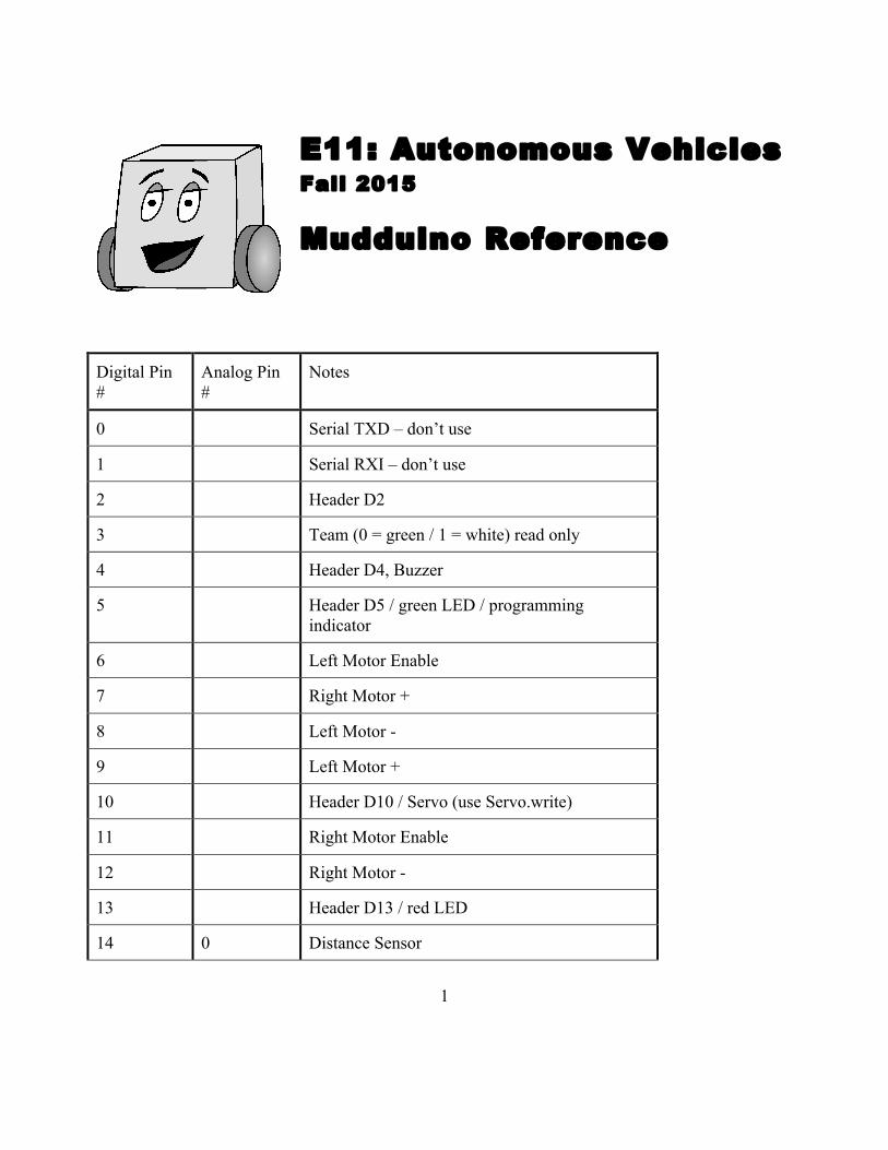
1 E11: Autonomous Vehicles Fall 2015 Mudduino Reference Digital Pin # Analog Pin # Notes 0 Serial TXD – don’t use 1 Serial RXI – don’t use 2 Header D2 3 Team (0 = green / 1 = white) read only 4 Header D4, Buzzer 5 Header D5 / green LED / programming indicator 6 Left Motor Enable 7 Right Motor + 8 Left Motor - 9 Left Motor + 10 Header D10 / Servo (use Servo.write) 11 Right Motor Enable 12 Right Motor - 13 Header D13 / red LED 14 0 Distance Sensor

Welcome message from author
This document is posted to help you gain knowledge. Please leave a comment to let me know what you think about it! Share it to your friends and learn new things together.
Transcript
1
E11: Autonomous Vehicles
Fall 2015
Mudduino Reference
Digital Pin #
Analog Pin #
Notes
0 Serial TXD – don’t use
1 Serial RXI – don’t use
2 Header D2
3 Team (0 = green / 1 = white) read only
4 Header D4, Buzzer
5 Header D5 / green LED / programming indicator
6 Left Motor Enable
7 Right Motor +
8 Left Motor -
9 Left Motor +
10 Header D10 / Servo (use Servo.write)
11 Right Motor Enable
12 Right Motor -
13 Header D13 / red LED
14 0 Distance Sensor
2
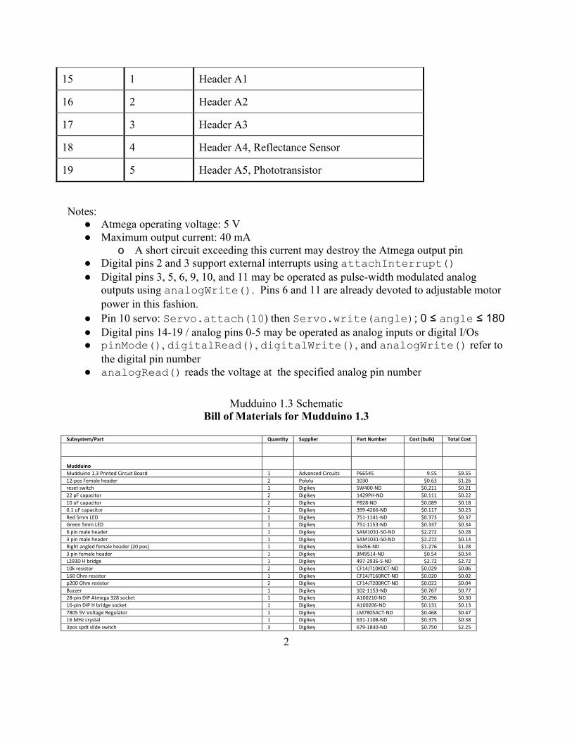
15 1 Header A1
16 2 Header A2
17 3 Header A3
18 4 Header A4, Reflectance Sensor
19 5 Header A5, Phototransistor
Notes: ● Atmega operating voltage: 5 V ● Maximum output current: 40 mA
o A short circuit exceeding this current may destroy the Atmega output pin ● Digital pins 2 and 3 support external interrupts using attachInterrupt() ● Digital pins 3, 5, 6, 9, 10, and 11 may be operated as pulse-width modulated analog
outputs using analogWrite(). Pins 6 and 11 are already devoted to adjustable motor power in this fashion.
● Pin 10 servo: Servo.attach(10) then Servo.write(angle); 0 ≤ angle ≤ 180 ● Digital pins 14-19 / analog pins 0-5 may be operated as analog inputs or digital I/Os ● pinMode(), digitalRead(), digitalWrite(), and analogWrite() refer to
the digital pin number ● analogRead() reads the voltage at the specified analog pin number
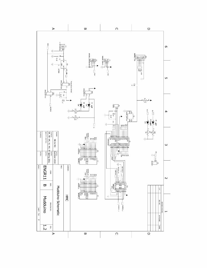
Mudduino 1.3 Schematic
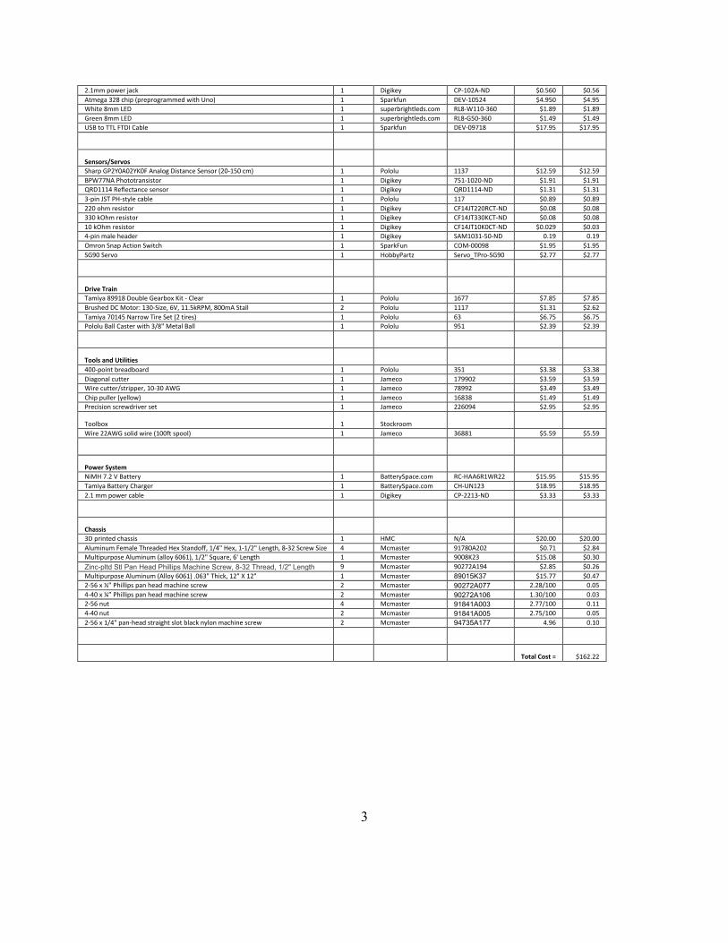
Bill of Materials for Mudduino 1.3
Subsystem/Part Quantity Supplier Part Number Cost (bulk) Total Cost Mudduino Mudduino 1.3 Printed Circuit Board 1 Advanced Circuits P66545 9.55 $9.55 12-‐pos Female header 2 Pololu 1030 $0.63 $1.26 reset switch 1 Digikey SW400-‐ND $0.211 $0.21 22 pF capacitor 2 Digikey 1429PH-‐ND $0.111 $0.22 10 uF capacitor 2 Digikey P828-‐ND $0.089 $0.18 0.1 uF capacitor 2 Digikey 399-‐4266-‐ND $0.117 $0.23 Red 5mm LED 1 Digikey 751-‐1141-‐ND $0.373 $0.37 Green 5mm LED 1 Digikey 751-‐1153-‐ND $0.337 $0.34 6 pin male header 1 Digikey SAM1031-‐50-‐ND $2.272 $0.28 3 pin male header 1 Digikey SAM1031-‐50-‐ND $2.272 $0.14 Right angled female header (20 pos) 1 Digikey S5456-‐ND $1.276 $1.28 3 pin female header 1 Digikey 3M9514-‐ND $0.54 $0.54 L293D H bridge 1 Digikey 497-‐2936-‐5-‐ND $2.72 $2.72 10k resistor 2 Digikey CF14JT10K0CT-‐ND $0.029 $0.06 160 Ohm resistor 1 Digikey CF14JT160RCT-‐ND $0.020 $0.02 p200 Ohm resistor 2 Digikey CF14JT200RCT-‐ND $0.022 $0.04 Buzzer 1 Digikey 102-‐1153-‐ND $0.767 $0.77 28-‐pin DIP Atmega 328 socket 1 Digikey A100210-‐ND $0.296 $0.30 16-‐pin DIP H bridge socket 1 Digikey A100206-‐ND $0.131 $0.13 7805 5V Voltage Regulator 1 Digikey LM7805ACT-‐ND $0.468 $0.47 16 MHz crystal 1 Digikey 631-‐1108-‐ND $0.375 $0.38 3pos spdt slide switch 3 Digikey 679-‐1840-‐ND $0.750 $2.25
3
2.1mm power jack 1 Digikey CP-‐102A-‐ND $0.560 $0.56 Atmega 328 chip (preprogrammed with Uno) 1 Sparkfun DEV-‐10524 $4.950 $4.95 White 8mm LED 1 superbrightleds.com RL8-‐W110-‐360 $1.89 $1.89 Green 8mm LED 1 superbrightleds.com RL8-‐G50-‐360 $1.49 $1.49 USB to TTL FTDI Cable 1 Sparkfun DEV-‐09718 $17.95 $17.95 Sensors/Servos Sharp GP2Y0A02YK0F Analog Distance Sensor (20-‐150 cm) 1 Pololu 1137 $12.59 $12.59 BPW77NA Phototransistor 1 Digikey 751-‐1020-‐ND $1.91 $1.91 QRD1114 Reflectance sensor 1 Digikey QRD1114-‐ND $1.31 $1.31 3-‐pin JST PH-‐style cable 1 Pololu 117 $0.89 $0.89 220 ohm resistor 1 Digikey CF14JT220RCT-‐ND $0.08 $0.08 330 kOhm resistor 1 Digikey CF14JT330KCT-‐ND $0.08 $0.08 10 kOhm resistor 1 Digikey CF14JT10K0CT-‐ND $0.029 $0.03 4-‐pin male header 1 Digikey SAM1031-‐50-‐ND 0.19 0.19 Omron Snap Action Switch 1 SparkFun COM-‐00098 $1.95 $1.95 SG90 Servo 1 HobbyPartz Servo_TPro-‐SG90 $2.77 $2.77 Drive Train Tamiya 89918 Double Gearbox Kit -‐ Clear 1 Pololu 1677 $7.85 $7.85 Brushed DC Motor: 130-‐Size, 6V, 11.5kRPM, 800mA Stall 2 Pololu 1117 $1.31 $2.62 Tamiya 70145 Narrow Tire Set (2 tires) 1 Pololu 63 $6.75 $6.75 Pololu Ball Caster with 3/8" Metal Ball 1 Pololu 951 $2.39 $2.39 Tools and Utilities 400-‐point breadboard 1 Pololu 351 $3.38 $3.38 Diagonal cutter 1 Jameco 179902 $3.59 $3.59 Wire cutter/stripper, 10-‐30 AWG 1 Jameco 78992 $3.49 $3.49 Chip puller (yellow) 1 Jameco 16838 $1.49 $1.49 Precision screwdriver set 1 Jameco 226094 $2.95 $2.95 Toolbox 1 Stockroom Wire 22AWG solid wire (100ft spool) 1 Jameco 36881 $5.59 $5.59 Power System NiMH 7.2 V Battery 1 BatterySpace.com RC-‐HAA6R1WR22 $15.95 $15.95 Tamiya Battery Charger 1 BatterySpace.com CH-‐UN123 $18.95 $18.95 2.1 mm power cable 1 Digikey CP-‐2213-‐ND $3.33 $3.33 Chassis 3D printed chassis 1 HMC N/A $20.00 $20.00 Aluminum Female Threaded Hex Standoff, 1/4" Hex, 1-‐1/2" Length, 8-‐32 Screw Size 4 Mcmaster 91780A202 $0.71 $2.84 Multipurpose Aluminum (alloy 6061), 1/2" Square, 6' Length 1 Mcmaster 9008K23 $15.08 $0.30 Zinc-pltd Stl Pan Head Phillips Machine Screw, 8-32 Thread, 1/2" Length 9 Mcmaster 90272A194 $2.85 $0.26 Multipurpose Aluminum (Alloy 6061) .063" Thick, 12" X 12" 1 Mcmaster 89015K37 $15.77 $0.47 2-‐56 x ¼” Phillips pan head machine screw 2 Mcmaster 90272A077 2.28/100 0.05 4-‐40 x ¼” Phillips pan head machine screw 2 Mcmaster 90272A106 1.30/100 0.03 2-‐56 nut 4 Mcmaster 91841A003 2.77/100 0.11 4-‐40 nut 2 Mcmaster 91841A005 2.75/100 0.05 2-‐56 x 1/4" pan-‐head straight slot black nylon machine screw 2 Mcmaster 94735A177 4.96 0.10 Total Cost = $162.22
4

5
6
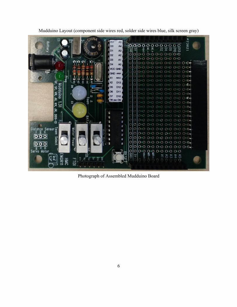
Mudduino Layout (component side wires red, solder side wires blue, silk screen gray)
Photograph of Assembled Mudduino Board
Related Documents