E User Description, Frequency Hopping User Description, Frequency Hopping © Ericsson Radio Systems AB 8/1553-HSC 103 12 Uen Rev C 1999-02-12 1 (29) © Ericsson Radio Systems AB

Welcome message from author
This document is posted to help you gain knowledge. Please leave a comment to let me know what you think about it! Share it to your friends and learn new things together.
Transcript
E User Description, Frequency Hopping
User Description, FrequencyHopping© Ericsson Radio Systems AB
8/1553-HSC 103 12 Uen Rev C
1999-02-121 (29)© Ericsson Radio Systems AB
User Description, Frequency Hopping
2 (29) 8/1553-HSC 103 12 Uen Rev C
1999-02-12© Ericsson Radio Systems AB
User Description, Frequency Hopping
Contents1 Feature overview........................................................................................... 5
1.1 Introduction.............................................................................................. 5
1.2 Background.............................................................................................. 5
1.3 What can be achieved............................................................................. 6
2 Technical description................................................................................... 9
2.1 General .................................................................................................... 9
2.2 Baseband hopping................................................................................... 9
2.3 Synthesizer hopping................................................................................10
2.4 Configuration............................................................................................10
2.5 Algorithm..................................................................................................15
2.6 Main changes in Ericsson GSM System R7/BSS R7.1..........................17
3 Engineering guidelines.................................................................................19
3.1 Applications..............................................................................................19
3.2 Impact of frequency hopping on frequency planning..............................21
3.3 Channel configuration..............................................................................22
3.4 Frequency hopping and subjective speech quality.................................24
4 Parameters.....................................................................................................27
4.1 Main controlling parameters ....................................................................27
4.2 Value ranges and default values.............................................................27
5 References.....................................................................................................29
8/1553-HSC 103 12 Uen Rev C
1999-02-123 (29)© Ericsson Radio Systems AB
User Description, Frequency Hopping
This page is intentionally left blank
4 (29) 8/1553-HSC 103 12 Uen Rev C
1999-02-12© Ericsson Radio Systems AB
Feature overview
1 Feature overview
1.1 IntroductionFrequency hopping means that multiple frequencies are used for thetransmission of speech, signalling or data in a single connection. Eachburst for the connection is transmitted on a fixed frequency, but thefrequency is changed between bursts. A burst can easily be lost whenthe mobile station happens to be located in a fading dip for thatparticular frequency, or if it is subjected to interference. The next burst,if on a different frequency, has a good chance to come through. Thecoding and interleaving scheme in GSM is constructed so that loss of asingle burst have minimal influence on the speech quality.
A predefined set of frequencies is used in each cell. The mobile stationand the base station can change frequency between every burst, i.e. 217times per second.
The Frequency Hopping feature is implemented in the Base StationController (BSC).
1.2 Background
1.2.1 General
During a call, a number of physical effects influence the perceived radioenvironment between a mobile station and a base station. One sucheffect is multipath fading, which is caused by the multiple propagationpaths the signal can take to the receiver. Depending on the difference inpath length, a constructive or destructive signal summation can beobtained, resulting in variations in the received signal strength, i.e.fading.
Another effect is various types of interference. The dominating type isnormally co-channel interference, but other types, such as adjacentchannel interference, intermodulation products, military sources etc.must be considered as well. The interference varies as the interferersswitch on and off. In the worst case, however, the interference remainsduring the entire call.
The time intervals of low received signal strength due to multipathfading are often fairly long for a slowly moving mobile station, if a fixedfrequency is used. The duration of persistent co-channel interference isalso usually fairly long. For both of these cases, the coding andinterleaving are not adequate to protect the signal information.
1.2.2 Multipath fading
The destructive signal summation produced by multipath propagation iscalled “fading dips”. Fading dips may cause speech quality degradation.For a fix frequency, multipath fading dips in the radio signal arenormally separated in space approximately by one half wavelength (i.e.17 cm for GSM 900, and approximately 8 cm for GSM 1800 and GSM1900). If the antenna of the mobile station is placed in such a dip (e.g.when a car stops at red light, the so called red light problem), thespeech quality can become unacceptable. For different frequencies, thefading dips occur at slightly different positions in space.
8/1553-HSC 103 12 Uen Rev C
1999-02-125 (29)© Ericsson Radio Systems AB
Feature overview
1.2.3 Co-channel interference
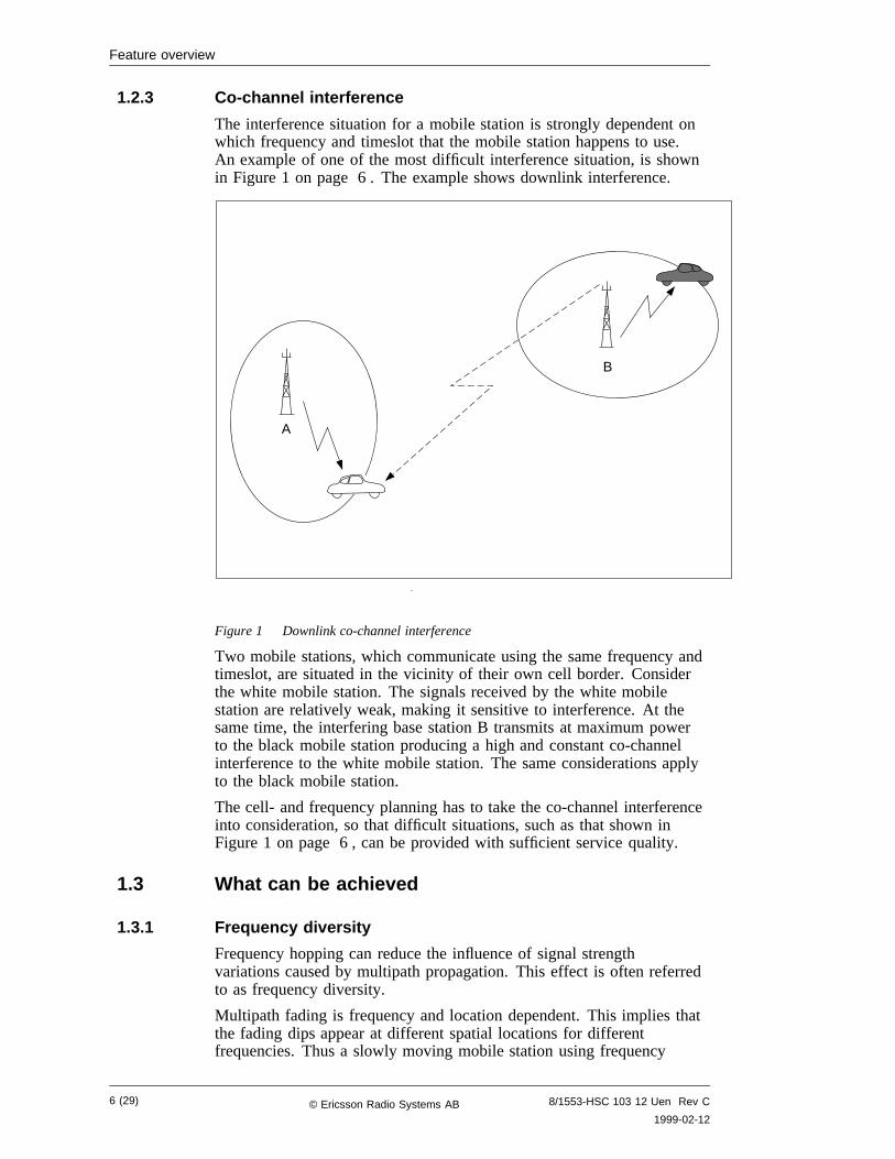
The interference situation for a mobile station is strongly dependent onwhich frequency and timeslot that the mobile station happens to use.An example of one of the most difficult interference situation, is shownin Figure 1 on page 6 . The example shows downlink interference.
A
B
Figure 1 Downlink co-channel interference
Two mobile stations, which communicate using the same frequency andtimeslot, are situated in the vicinity of their own cell border. Considerthe white mobile station. The signals received by the white mobilestation are relatively weak, making it sensitive to interference. At thesame time, the interfering base station B transmits at maximum powerto the black mobile station producing a high and constant co-channelinterference to the white mobile station. The same considerations applyto the black mobile station.
The cell- and frequency planning has to take the co-channel interferenceinto consideration, so that difficult situations, such as that shown inFigure 1 on page 6 , can be provided with sufficient service quality.
1.3 What can be achieved
1.3.1 Frequency diversity
Frequency hopping can reduce the influence of signal strengthvariations caused by multipath propagation. This effect is often referredto as frequency diversity.
Multipath fading is frequency and location dependent. This implies thatthe fading dips appear at different spatial locations for differentfrequencies. Thus a slowly moving mobile station using frequency
6 (29) 8/1553-HSC 103 12 Uen Rev C
1999-02-12© Ericsson Radio Systems AB
Feature overview
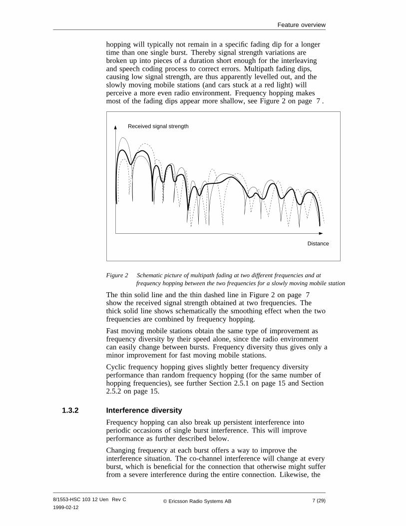
hopping will typically not remain in a specific fading dip for a longertime than one single burst. Thereby signal strength variations arebroken up into pieces of a duration short enough for the interleavingand speech coding process to correct errors. Multipath fading dips,causing low signal strength, are thus apparently levelled out, and theslowly moving mobile stations (and cars stuck at a red light) willperceive a more even radio environment. Frequency hopping makesmost of the fading dips appear more shallow, see Figure 2 on page 7 .
Distance
Received signal strength
Figure 2 Schematic picture of multipath fading at two different frequencies and atfrequency hopping between the two frequencies for a slowly moving mobile station
The thin solid line and the thin dashed line in Figure 2 on page 7show the received signal strength obtained at two frequencies. Thethick solid line shows schematically the smoothing effect when the twofrequencies are combined by frequency hopping.
Fast moving mobile stations obtain the same type of improvement asfrequency diversity by their speed alone, since the radio environmentcan easily change between bursts. Frequency diversity thus gives only aminor improvement for fast moving mobile stations.
Cyclic frequency hopping gives slightly better frequency diversityperformance than random frequency hopping (for the same number ofhopping frequencies), see further Section 2.5.1 on page 15 and Section2.5.2 on page 15.
1.3.2 Interference diversity
Frequency hopping can also break up persistent interference intoperiodic occasions of single burst interference. This will improveperformance as further described below.
Changing frequency at each burst offers a way to improve theinterference situation. The co-channel interference will change at everyburst, which is beneficial for the connection that otherwise might sufferfrom a severe interference during the entire connection. Likewise, the
8/1553-HSC 103 12 Uen Rev C
1999-02-127 (29)© Ericsson Radio Systems AB
Feature overview
interference that one connection is causing, is spread out to a number ofconnections in single bursts. This effect is called interference averaging.The radio environment, in terms of interference characteristics, will bemore even.
Occasionally there will be frequency collisions causing stronginterference, but with very short durations. Again, the coding andinterleaving will get a chance to deal with the situation. The timevarying interference increases coding and interleaving efficiency and acoding gain is achieved. The transmission link will thereby become lesssensitive to interference.
These two considerations also apply to other types of interference suchas, adjacent channel, intermodulation products etc.
Frequency hopping thus introduces an interference diversity. The cellplanning margin for the interference can be reduced which makes itpossible to implement a tigther frequency plan.
The interference diversity is independent of the mobile speed, but it ishighly dependent on the mode of hopping, cyclic or random. Thegreatest improvement is obtained when the interferer and the interferedconnections use hopping sequences that are independent of each other,i.e. no correlation between them (see Section 2.5.4 on page 16). Thelower the correlation, the higher the averaging gain. If the interferer andthe interfered connection both use cyclic hopping and, in addition, thesame frequencies, they may get in phase with one another. The twoconnections will then hop between the frequencies, hand in hand, andthe co-channel interference will persist as if there was no frequencyhopping at all. The effect is total correlation, and the resultingimprovement will be very small.
The number of frequencies used for hopping is also important for theinterference diversity gain. The more the better since the interference isspread over a larger bandwidth (provides a better averaging effect) andthe interference collisions may also be fewer. In a fully loaded system,all possible interferers will be transmitting and consequently interferingin every timeslot, but random frequency hopping will still show aperformance gain. However, a requirement is that co-channel cells usedifferent (independent) hopping sequences, see further Section 2.5.4 onpage 16.
1.3.3 Conclusions
From a subscriber point of view, frequency hopping gives an improvedspeech quality in many situations. From an operator point of view, thebenefits are:
• a possibility to decrease the cell planning margin, which might beused to employ a tighter frequency reuse yielding a capacityincrease,
• a more robust radio environment,
• a possibility to give the subscribers a more uniform speech quality.
The effects increase with the number of frequencies used for hoppingsequence, but the relative benefit of adding yet another frequency willdiminish, see further Section 3.1.2 on page 19.
8 (29) 8/1553-HSC 103 12 Uen Rev C
1999-02-12© Ericsson Radio Systems AB
Technical description
2 Technical description
2.1 GeneralFrequency hopping in the base stations can be implemented in twobasic ways, baseband hopping or synthesizer hopping, each with itspros and cons. ParameterFHOP specifies which method to be used inthe entire base station. The Frequency Hopping feature as such isswitched on and off separately for each channel group with parameterHOP, see Section 2.4.1 on page 10.
The frequency hopping can be performed on the Traffic Channels(TCHs) and the Stand alone Dedicated Control Channels (SDCCHs).However, broadcast and common control channels such as e.g. theBroadcast Control Channel (BCCH) are not allowed to hop. Theseimportant channels are mapped on timeslot 0 on the so called BCCHfrequency required for each base station.
In the following, baseband and synthesizer hopping is explained with theuse of some simple examples of combiner and antenna configurations.The actual configuration however, depends on the base station (RBS200or RBS2000) and on the type of combiner that is installed.
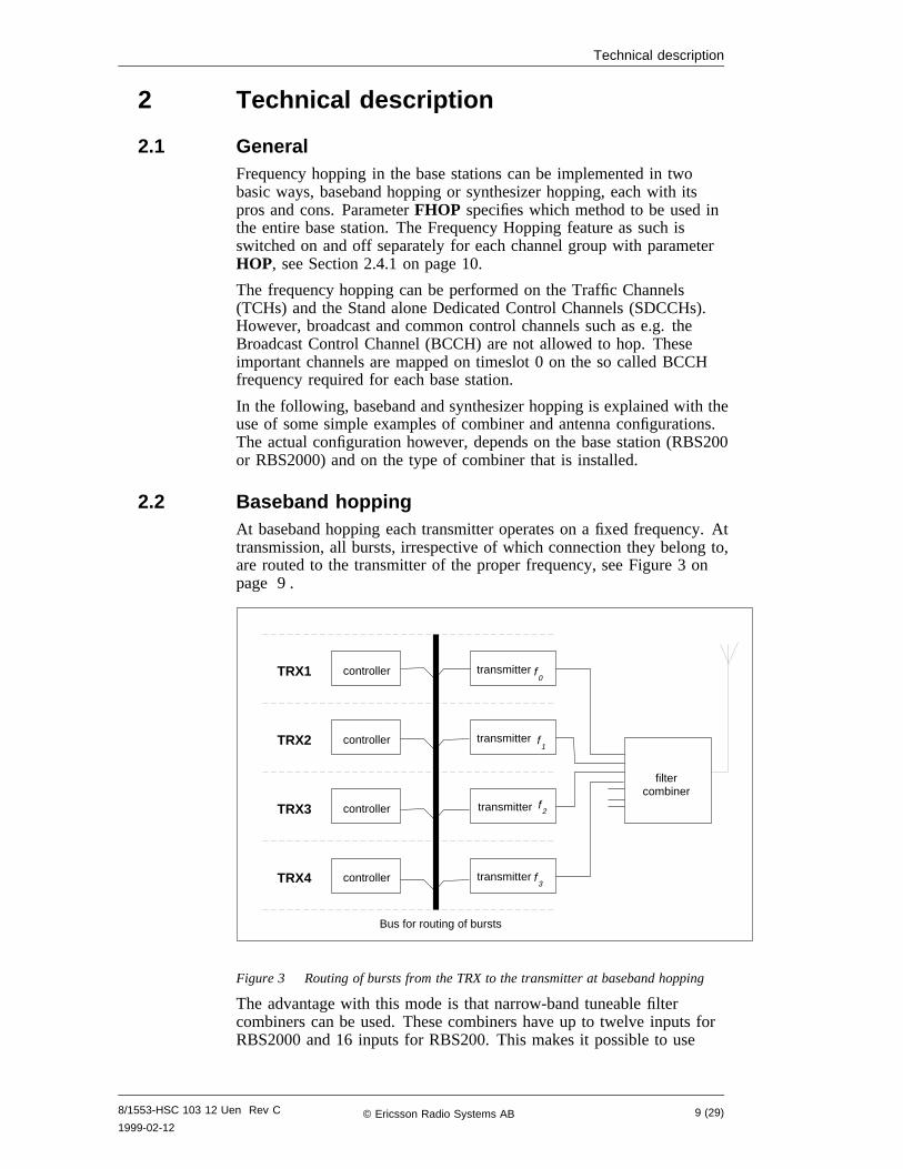
2.2 Baseband hoppingAt baseband hopping each transmitter operates on a fixed frequency. Attransmission, all bursts, irrespective of which connection they belong to,are routed to the transmitter of the proper frequency, see Figure 3 onpage 9 .
TRX1 controller
controller
controller
controller
TRX2
TRX3
TRX4 transmitter3
f
transmitter 2f
transmitter1
f
transmitter0
f
filtercombiner
Bus for routing of bursts
Figure 3 Routing of bursts from the TRX to the transmitter at baseband hopping
The advantage with this mode is that narrow-band tuneable filtercombiners can be used. These combiners have up to twelve inputs forRBS2000 and 16 inputs for RBS200. This makes it possible to use
8/1553-HSC 103 12 Uen Rev C
1999-02-129 (29)© Ericsson Radio Systems AB
Technical description
many transceivers without having to connect several combiners incascade.
The disadvantage is that it is not possible to use a larger number offrequencies in the hopping sequence than there are transmitters.
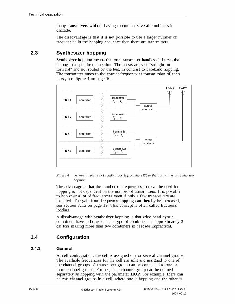
2.3 Synthesizer hoppingSynthesizer hopping means that one transmitter handles all bursts thatbelong to a specific connection. The bursts are sent “straight onforward” and not routed by the bus, in contrast to baseband hopping.The transmitter tunes to the correct frequency at transmission of eachburst, see Figure 4 on page 10.
TRX1 controller
controller
controller
controller
TRX2
TRX3
TRX4
0f
nf...
transmitter
0f
nf...
transmitter
0f
nf...
transmitter
0f
nf...
transmitter
0f
nf...
hybridcombiner
TX/RX TX/RX
hybridcombiner
Figure 4 Schematic picture of sending bursts from the TRX to the transmitter at synthesizerhopping
The advantage is that the number of frequencies that can be used forhopping is not dependent on the number of transmitters. It is possibleto hop over a lot of frequencies even if only a few transceivers areinstalled. The gain from frequency hopping can thereby be increased,see Section 3.1.2 on page 19. This concept is often called fractionalloading.
A disadvantage with synthesizer hopping is that wide-band hybridcombiners have to be used. This type of combiner has approximately 3dB loss making more than two combiners in cascade impractical.
2.4 Configuration
2.4.1 General
At cell configuration, the cell is assigned one or several channel groups.The available frequencies for the cell are split and assigned to one ofthe channel groups. A transceiver group can be connected to one ormore channel groups. Further, each channel group can be definedseparately as hopping with the parameterHOP. For example, there canbe two channel groups in a cell, where one is hopping and the other is
10 (29) 8/1553-HSC 103 12 Uen Rev C
1999-02-12© Ericsson Radio Systems AB
Technical description
not. Within each channel group, the channels will hop over thefrequencies defined for that particular channel group. SDCCHs as wellas TCHs can hop. Timeslot 0 on the BCCH frequency will not hop,even if it belongs to a channel group that is configured as hopping.
The BCCH frequency must always be transmitting. If there are notraffic bursts to be transmitted, there still must be transmission of radioenergy on all burst in the downlink at the BCCH frequency. This isprovided by the transmitter itself. If it is configured for a singlefrequency, it can be set up so that it transmits dummy bursts whenevernothing else arrives from the controllers via the bus. This is calledcarrier-zero (c0) filling when applied to the BCCH frequencyf0. The c0filling is obtained automatically for the channel group containing theBCCH frequency.
For baseband hopping, thec0 filling is straightforward (see Section 2.4.2on page 11). For synthesizer hopping, thec0 filling is morecomplicated. There are two configuration options, one with the BCCHfrequency included in the hopping set (see Section 2.4.3 on page 12),and the other with the BCCH frequency in a separate non-hoppingchannel group (see Section 2.4.4 on page 14).
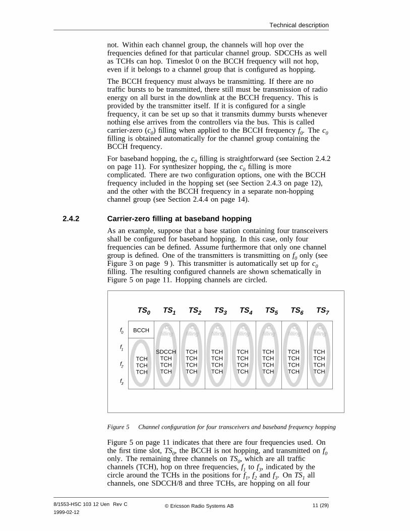
2.4.2 Carrier-zero filling at baseband hopping
As an example, suppose that a base station containing four transceiversshall be configured for baseband hopping. In this case, only fourfrequencies can be defined. Assume furthermore that only one channelgroup is defined. One of the transmitters is transmitting onf0 only (seeFigure 3 on page 9 ). This transmitter is automatically set up forc0filling. The resulting configured channels are shown schematically inFigure 5 on page 11. Hopping channels are circled.
TS0
BCCH
TCHTCHTCH
TS1 TS2 TS3 TS4 TS5 TS6 TS7
SDCCHTCHTCHTCH
TCHTCHTCHTCH
TCHTCHTCHTCH
TCHTCHTCHTCH
TCHTCHTCHTCH
TCHTCHTCHTCH
TCHTCHTCHTCH
f0
f1
f2
f3
Cfilling
0 Cfilling
0 Cfilling
0 Cfilling
0 Cfilling
0 Cfilling
0 Cfilling
0
Figure 5 Channel configuration for four transceivers and baseband frequency hopping
Figure 5 on page 11 indicates that there are four frequencies used. Onthe first time slot,TS0, the BCCH is not hopping, and transmitted onf0only. The remaining three channels onTS0, which are all trafficchannels (TCH), hop on three frequencies,f1 to f3, indicated by thecircle around the TCHs in the positions forf1, f2 and f3. On TS1 allchannels, one SDCCH/8 and three TCHs, are hopping on all four
8/1553-HSC 103 12 Uen Rev C
1999-02-1211 (29)© Ericsson Radio Systems AB
Technical description
frequencies,f0 to f3, as indicated by the circle. On the remaining timeslots, there are four TCHs hopping on all four frequencies.
2.4.3 Carrier-zero filling at synthesizer hopping: the BCCH frequencyincluded
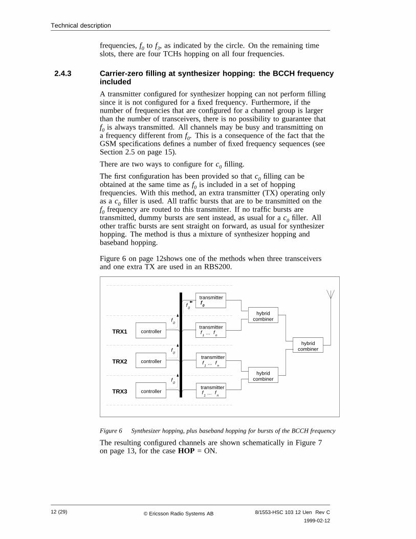
A transmitter configured for synthesizer hopping can not perform fillingsince it is not configured for a fixed frequency. Furthermore, if thenumber of frequencies that are configured for a channel group is largerthan the number of transceivers, there is no possibility to guarantee thatf0 is always transmitted. All channels may be busy and transmitting ona frequency different fromf0. This is a consequence of the fact that theGSM specifications defines a number of fixed frequency sequences (seeSection 2.5 on page 15).
There are two ways to configure forc0 filling.
The first configuration has been provided so thatc0 filling can beobtained at the same time asf0 is included in a set of hoppingfrequencies. With this method, an extra transmitter (TX) operating onlyas ac0 filler is used. All traffic bursts that are to be transmitted on thef0 frequency are routed to this transmitter. If no traffic bursts aretransmitted, dummy bursts are sent instead, as usual for ac0 filler. Allother traffic bursts are sent straight on forward, as usual for synthesizerhopping. The method is thus a mixture of synthesizer hopping andbaseband hopping.
Figure 6 on page 12shows one of the methods when three transceiversand one extra TX are used in an RBS200.
TRX1 controller
controller
controller
TRX2
TRX3
0ftransmitter
0f
transmitter
1f
nf...
transmitter
1f
nf...
transmitter
1f
nf...
hybridcombiner
hybridcombiner
hybridcombiner
0f
0f
0f
0f
Figure 6 Synthesizer hopping, plus baseband hopping for bursts of the BCCH frequency
The resulting configured channels are shown schematically in Figure 7on page 13, for the caseHOP = ON.
12 (29) 8/1553-HSC 103 12 Uen Rev C
1999-02-12© Ericsson Radio Systems AB
Technical description
TS0
BCCH
TCHTCH
TS1 TS2 TS3 TS4 TS5 TS6 TS7
SDCCHTCHTCH
TCHTCHTCH
TCHTCHTCH
TCHTCHTCH
TCHTCHTCH
TCHTCHTCH
TCHTCHTCH
f0
f1
f2
f3
fn
...
Cfilling
0 Cfilling
0 Cfilling
0 Cfilling
0 Cfilling
0 Cfilling
0 Cfilling
0
Figure 7 Channel configuration for three transceivers and one extra transmitter, frequencyhopping with the BCCH frequency included
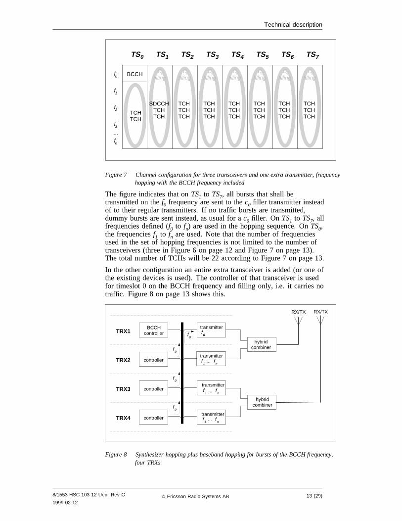
The figure indicates that onTS1 to TS7, all bursts that shall betransmitted on thef0 frequency are sent to thec0 filler transmitter insteadof to their regular transmitters. If no traffic bursts are transmitted,dummy bursts are sent instead, as usual for ac0 filler. On TS1 to TS7, allfrequencies defined (f0 to fn) are used in the hopping sequence. OnTS0,the frequenciesf1 to fn are used. Note that the number of frequenciesused in the set of hopping frequencies is not limited to the number oftransceivers (three in Figure 6 on page 12 and Figure 7 on page 13).The total number of TCHs will be 22 according to Figure 7 on page 13.
In the other configuration an entire extra transceiver is added (or one ofthe existing devices is used). The controller of that transceiver is usedfor timeslot 0 on the BCCH frequency and filling only, i.e. it carries notraffic. Figure 8 on page 13 shows this.
TRX1
controller
controller
controller
TRX2
TRX3
0ftransmitter
0f
transmitter
1f
nf...
transmitter
1f
nf...
transmitter
1f
nf...
hybridcombiner
0f
0f
0f
0f
BCCHcontroller
TRX4
RX/TX RX/TX
hybridcombiner
Figure 8 Synthesizer hopping plus baseband hopping for bursts of the BCCH frequency,four TRXs
8/1553-HSC 103 12 Uen Rev C
1999-02-1213 (29)© Ericsson Radio Systems AB
Technical description
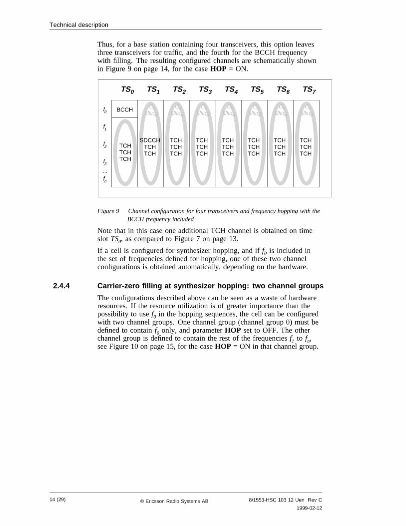
Thus, for a base station containing four transceivers, this option leavesthree transceivers for traffic, and the fourth for the BCCH frequencywith filling. The resulting configured channels are schematically shownin Figure 9 on page 14, for the caseHOP = ON.
TS0
BCCH
TCHTCHTCH
TS1 TS2 TS3 TS4 TS5 TS6 TS7
SDCCHTCHTCH
TCHTCHTCH
TCHTCHTCH
TCHTCHTCH
TCHTCHTCH
TCHTCHTCH
TCHTCHTCH
f0
f1
f2
f3
fn
...
Cfilling
0 Cfilling
0 Cfilling
0 Cfilling
0 Cfilling
0 Cfilling
0 Cfilling
0
Figure 9 Channel configuration for four transceivers and frequency hopping with theBCCH frequency included
Note that in this case one additional TCH channel is obtained on timeslot TS0, as compared to Figure 7 on page 13.
If a cell is configured for synthesizer hopping, and iff0 is included inthe set of frequencies defined for hopping, one of these two channelconfigurations is obtained automatically, depending on the hardware.
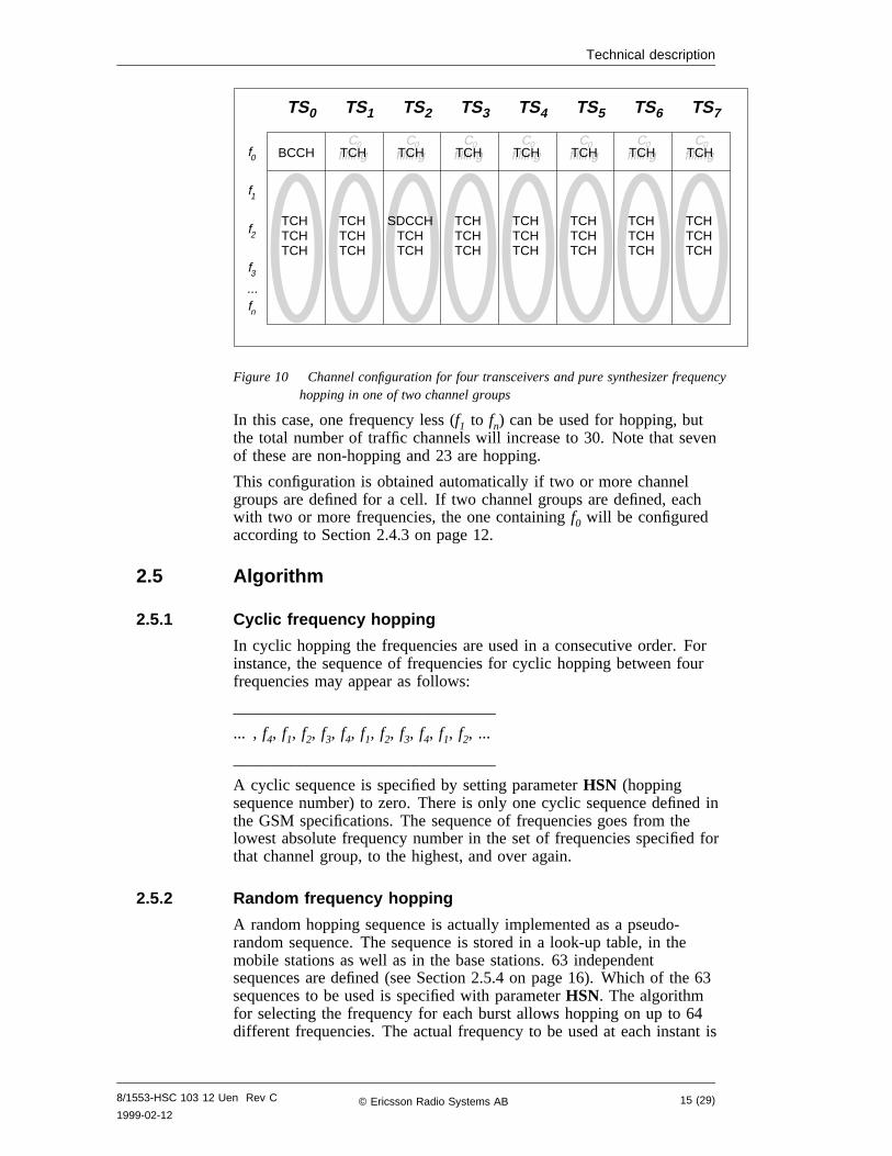
2.4.4 Carrier-zero filling at synthesizer hopping: two channel groups
The configurations described above can be seen as a waste of hardwareresources. If the resource utilization is of greater importance than thepossibility to usef0 in the hopping sequences, the cell can be configuredwith two channel groups. One channel group (channel group 0) must bedefined to containf0 only, and parameterHOP set to OFF. The otherchannel group is defined to contain the rest of the frequenciesf1 to fn,see Figure 10 on page 15, for the caseHOP = ON in that channel group.
14 (29) 8/1553-HSC 103 12 Uen Rev C
1999-02-12© Ericsson Radio Systems AB
Technical description
TS0
BCCH
TS1 TS2 TS3 TS4 TS5 TS6 TS7
TCHTCHTCH
SDCCHTCHTCH
TCHTCHTCH
TCHTCHTCH
TCHTCHTCH
TCHTCHTCH
TCHTCHTCH
Cfilling
0 Cfilling
0 Cfilling
0 Cfilling
0 Cfilling
0 Cfilling
0 Cfilling
0f0
f1
f2
f3
fn
...
TCHTCHTCH
TCH TCH TCH TCH TCH TCH TCH
Figure 10 Channel configuration for four transceivers and pure synthesizer frequencyhopping in one of two channel groups
In this case, one frequency less (f1 to fn) can be used for hopping, butthe total number of traffic channels will increase to 30. Note that sevenof these are non-hopping and 23 are hopping.
This configuration is obtained automatically if two or more channelgroups are defined for a cell. If two channel groups are defined, eachwith two or more frequencies, the one containingf0 will be configuredaccording to Section 2.4.3 on page 12.
2.5 Algorithm
2.5.1 Cyclic frequency hopping
In cyclic hopping the frequencies are used in a consecutive order. Forinstance, the sequence of frequencies for cyclic hopping between fourfrequencies may appear as follows:
________________________________
... , f4, f1, f2, f3, f4, f1, f2, f3, f4, f1, f2, ...
________________________________
A cyclic sequence is specified by setting parameterHSN (hoppingsequence number) to zero. There is only one cyclic sequence defined inthe GSM specifications. The sequence of frequencies goes from thelowest absolute frequency number in the set of frequencies specified forthat channel group, to the highest, and over again.
2.5.2 Random frequency hopping
A random hopping sequence is actually implemented as a pseudo-random sequence. The sequence is stored in a look-up table, in themobile stations as well as in the base stations. 63 independentsequences are defined (see Section 2.5.4 on page 16). Which of the 63sequences to be used is specified with parameterHSN. The algorithmfor selecting the frequency for each burst allows hopping on up to 64different frequencies. The actual frequency to be used at each instant is
8/1553-HSC 103 12 Uen Rev C
1999-02-1215 (29)© Ericsson Radio Systems AB
Technical description
obtained by a modulo operation with the available frequencies, seeGSM Specification 05.02.
When random hopping is used, the frequencies will be used (pseudo-)randomly, and a hopping sequence for four frequencies may appear asfollows:
________________________________
... , f1, f4, f4, f3, f1, f2, f4, f1, f3, f3, f2, ...
________________________________
The period for a random sequence is approximately 6 minutes.
2.5.3 Orthogonal sequences
In the baseband hopping example in Figure 5 on page 11, a base stationis configured with four transceivers. They will be given the sameHSN.In order not to interfere with each other, they must not use the samefrequency simultaneously. This is calledorthogonality. All channels ina cell must be orthogonal since non-orthogonal channels will causeco-channel interference within the cell.
This problem is solved by using a frequency offset which is alsoreferred to as the Mobile Allocation Index Offset (MAIO), see GSMspecification 05.02. Each transceiver is assigned a unique MAIO atconfiguration since two transceivers bearing the sameHSN but differentMAIOs never use the same frequency on burst basis. In this way, allchannels use the same hopping sequence, but different frequencies ateach instance in time (i.e. on burst level). The random sequence inFigure 5 on page 11 will appear as follows:
________________________________
... , f1, f4, f4, f3, f1, f2, f4, f1, f3, f3, f2, ...
... , f2, f1, f1, f4, f2, f3, f1, f2, f4, f4, f3, ...
... , f3, f2, f2, f1, f3, f4, f2, f3, f1, f1, f4, ...
... , f4, f3, f3, f2, f4, f1, f3, f4, f2, f2, f1, ...
________________________________
The hopping channels hence never use the same frequencysimultaneously.
2.5.4 Independent sequences
For the interference averaging mechanism to work well, the sequence offrequencies in co-channel cells must be different. This is even moreimportant if the cells use exactly the same frequency set. Connectionsin these cells will then use the same frequencies, but not always at thesame time. If the frequencies are independent, they will only interferewith each other now and then, when two (or more) bursts happen tocoincide in frequency. The number of collisions per second will dependon the number of frequencies in the channel group.
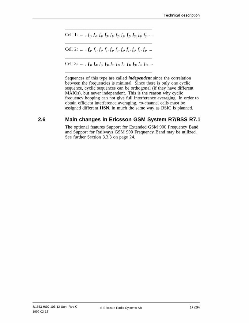
The sequences for three connections in three co-channel cells mightappear as follows for four frequencies in the hopping set. Thefrequency collisions, i.e. the instances of co-channel disturbance, areindicated with bold type:
16 (29) 8/1553-HSC 103 12 Uen Rev C
1999-02-12© Ericsson Radio Systems AB
Technical description
______________________________________
Cell 1: ... , f1, f4, f4, f3, f1, f2, f3, f1, f3, f4, f2, ...
______________________________________
Cell 2: ... , f3, f1, f1, f1, f4, f3, f2, f1, f2, f1, f4, ...
______________________________________
Cell 3: ... , f3, f4, f3, f3, f2, f1, f4, f1, f3, f2, f1, ...
______________________________________
Sequences of this type are calledindependentsince the correlationbetween the frequencies is minimal. Since there is only one cyclicsequence, cyclic sequences can be orthogonal (if they have differentMAIOs), but never independent. This is the reason why cyclicfrequency hopping can not give full interference averaging. In order toobtain efficient interference averaging, co-channel cells must beassigned differentHSN, in much the same way as BSIC is planned.
2.6 Main changes in Ericsson GSM System R7/BSS R7.1The optional features Support for Extended GSM 900 Frequency Bandand Support for Railways GSM 900 Frequency Band may be utilized.See further Section 3.3.3 on page 24.
8/1553-HSC 103 12 Uen Rev C
1999-02-1217 (29)© Ericsson Radio Systems AB
Technical description
This page is intentionally left blank
18 (29) 8/1553-HSC 103 12 Uen Rev C
1999-02-12© Ericsson Radio Systems AB
Engineering guidelines
3 Engineering guidelines
3.1 Applications
3.1.1 General
Frequency hopping should always be enabled in every cell since itintroduces frequency and interference diversity. The frequency diversitybalances the quality between slow and fast moving mobile stations, i.e.the quality for slow moving users is increased. Slow and fast users canthereby be treated in the same way when designing the radio network.Frequency diversity can be seen as a C/N (carrier to noise) gain. Theinterference diversity implies that the network can cope with a higherinterference level and thereby a tighter frequency reuse. This impliesincreased capacity compared to a non-hopping network. Theinterference diversity can, in its turn, be expressed as a C/I (carrier tointerference) gain. See also Section 1.3.1 on page 6 and Section 1.3.2on page 7 . Frequency hopping is the most important feature forsupporting high capacity networks with maintained quality. It alsomakes efficient use of DTX and power control.
3.1.2 Frequency hopping gain
The gain from frequency hopping depends on factors such aspropagation environment, number of hopping frequencies andinterference characteristics (e.g. time and strength variation).
The number of hopping frequencies affects the gain from bothfrequency and interference diversity. A large number of hoppingfrequencies increases the hopping gain. The more frequencies used forhopping, the larger gain is achieved, but there is a “law of diminishingreturns”. For example, increasing the number of frequencies in thehopping group from seven to eight does not give as much improvementas increasing it from two to three. Three hopping frequencies per cellresults in a substantial gain. With four frequencies per cell, it will workeven better. The more frequencies used for hopping the better since theinterference will then be spread over a larger bandwidth and in additionto that, the probability of being in a fading dip is reduced. Table 1summarizes the frequency hopping gain.
The interference diversity gain is also dependent on the use ofinterference reducing features such as DTX and power control. UsingDTX and power control increases the gain from the interferenceaveraging. In addition, the time variation of the interference is alsoimportant. The channel coding and interleaving schemes are notefficient when being hit by interference too often.
Frequency diversity for slowly moving mobile stations also depends onthe coherence bandwidth of the radio link, i.e. the correlation of fadingdips between different frequencies. Hopping over as few as twofrequencies will give frequency diversity if the two frequencies areseparated by more than the coherence bandwidth. In urbanenvironments with a lot of reflections present, there will be a substantialgain if the hopping frequencies are separated 1 MHz or more. Thecoherence bandwidth is strongly dependent upon the propagationenvironment and the presence of reflections (reflecting objects). More
8/1553-HSC 103 12 Uen Rev C
1999-02-1219 (29)© Ericsson Radio Systems AB

Engineering guidelines
reflections are better in this case. A line of sight connection will have asmaller gain, but fewer fading dips implying that a gain is really notneeded. Full frequency diversity gain is achieved for the TCH whenhopping over 8 frequencies since a speech frame is interleaved over 8bursts (for the SDCCH the corresponding limit is 4).
Table 1 Gain from frequency hopping
Interference diversity Frequency diversityNumber ofhoppingfrequencies
(C/I gain) (C/N gain)
2 Very small gain, and only ifhopping over 2 TCHfrequencies (BCCHfrequency not included inhopping sequence)
Substantial if carrierfrequencies separated bycoherence bandwidth:around 1 MHz, denseurban and urban scenarios
3 Significant gain Larger than with 2frequencies per cell
>=4 Larger than with 3frequencies per cell andincreasing if the traffic loadis kept low
Significantly larger thanwith 2 frequencies per cell
3.1.3 Cyclic or random hopping
The random hopping mode is superior for averaging the co-channelinterference. Random hopping is the hopping mode of choice for highcapacity networks. If random hopping is applied, co-channel cells (cellswhich have the same carrier frequencies in the hopping sequence)should have differentHSN.
3.1.4 Baseband or synthesizer hopping
The choice between baseband hopping and synthesizer hopping dependson the available hardware. Some properties of the synthesizer andbaseband hopping are summarized below:
• Number of TXs
In a synthesizer hopping system, the required number of TXs canbe less than the number of frequencies. In a baseband hoppingsystem, a dedicated TX is needed for each frequency.
• Combiner type
For the synthesizer hopping system, a hybrid combiner solution isrequired. Baseband hopping can also be specified if hybridcombiners are used. If a filter combiner is used then onlybaseband hopping can be specified.
• RBS200
The minimum channel separation in a hybrid combiner is 400kHz, while the minimum channel separation in a filter combiner is600 kHz (900 MHz band) and 1200 kHz (1800/1900 MHz band).
• RBS2000
20 (29) 8/1553-HSC 103 12 Uen Rev C
1999-02-12© Ericsson Radio Systems AB
Engineering guidelines
The minimum channel separation for CDU-A, CDU-C/C+ is 400kHz, while the minimum channel separation for CDU-D is 600kHz (900 MHz band) and 1000 kHz (1800/1900 MHz band).
• Faulty TX
In a synthesizer hopping system, a fault on a TX will affect up toeight Basic Physical Channels (BPCs) assigned to that TX. In abaseband hopping system, a fault on a TX will affect every BPCthat uses the frequency that the faulty TX was transmitting on.
A lost transceiver, included in a frequency hopping sequence, isisolated and hopping is restored without the faulty transceiver, butthe transceiver will not automatically be included in the hoppingsequence after a recovery.
It should be noted that the requirement on channel separation fordifferent combiner types can be disregarded in some cases. Insynthesizer hopping networks, it is even possible to have adjacentfrequencies (i.e. a channel separation of 0) in cells if the fractional loadis low (the number of transceivers are less than the number of hoppingfrequencies per cell) and DTX is utilized. The reason is that theprobability of being hit by adjacent channel interference from own cellis thereby made very low. The network can manage adjacencies, but theperformance is, of course, better without adjacencies.
3.2 Impact of frequency hopping on frequency planning
3.2.1 General
Frequency planning in a network is done with respect to an acceptableinterference level. This level can be set to a lower value in frequencyhopping network compared to a network without frequency hopping.
3.2.2 BCCH frequency planning
The broadcast and common control channels (e.g. the BCCH) carryinformation for identifying cells for access evaluation, paging andmeasurements on neighbour cells for locating evaluations. Because oftheir importance, great care should be taken to protect these channelsfrom interference. Furthermore, in a network using frequency hopping,the TCHs and the SDCCHs can be made hopping, but the broadcast andcommon control channels (mapped on timeslot 0 on the BCCHfrequency) are not hopping, and features like DTX and power controlcan not be applied on the BCCH frequency in the downlink. Hence, theBCCH frequency can not be planned according to a tight reuse pattern.A traditional 12 reuse is recommended for the BCCH frequencies formacrocells. It is further recommended to usea separate (dedicated)band for the BCCH frequencies.
3.2.3 High capacity networks
The general strategy is to boost the macrocell network capacity as a firststep. Deploying microcells in the later phases enables the operator toperform site hunting and establish procedures for the microcell roll-out.
8/1553-HSC 103 12 Uen Rev C
1999-02-1221 (29)© Ericsson Radio Systems AB
Engineering guidelines
The macrocell network capacity is increased by planning the TCHfrequencies using a tight frequency reuse, significantly tighter than 12.This is possible since the TCH is a more robust channel and becauseDTX and power control can be applied on the TCHs. Different highcapacity strategies can be employed depending on factors such as thecombiner type used in the network, the number of available frequenciesand number of transceivers per cell.
In networks using filter combiners and configured with manytransceivers per cell (3 or more), the Ericsson Multiple Reuse Patterns(MRP) methodology is preferred using baseband hopping. An averagereuse of typically 7-8 can be applied (the average reuse including theBCCH frequency reuse of 12). If DTX and power control are applied,an average reuse of down to 6 or even less is possible.
For networks using wide-band combiners, such as RBS2000 CDU-Aand CDU-C, it might be better to apply fractional loading usingsynthesizer hopping (especially if only a few frequencies are available).Thereby the hopping can be performed over more frequencies than thereare installed transceivers per cell in order to achieve a sufficientfrequency hopping gain. In this case, very tight reuse patterns like 1/3or 1/1 can be applied on the TCH frequencies.
As a second step, hotspot microcells based on the RBS2302 withsynthesizer hopping can be introduced to further boost the networkcapacity. In order to make the implementation easy, a few frequenciescan be reserved for the microcell BCCH frequencies. TCH frequenciesfor the microcells can be borrowed from the macrocell layer. As themicrocell network grows, it is a good option to further reservefrequencies for the microcells. A total allocation of 5-8 frequencies isnormally sufficient for a contiguous microcell layer configured with 2transceivers per cell.
3.3 Channel configuration
3.3.1 Baseband hopping
The following example illustrates the channel structure for a cell withbaseband frequency hopping.
Example:
Consider a cell without subcell structure using one channel group. Fourfrequencies are assigned to the cell in the 900 MHz band, defined byARFCN 75, 78, 81, and 84. The following parameter setting is definedfor the cell:
Table 2 Parameter setting, example
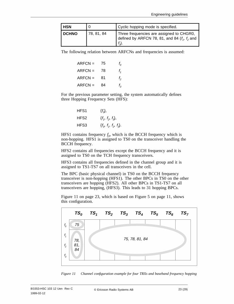
Parameter Value Description
BCCHNO 75 The frequency defined by ARFCN 75 isdefined as the BCCH frequency (f0).
CHGR 0 Channel group 0 is defined in the cell.
HOP ON Channel group 0 is hopping.
22 (29) 8/1553-HSC 103 12 Uen Rev C
1999-02-12© Ericsson Radio Systems AB
Engineering guidelines
HSN 0 Cyclic hopping mode is specified.
DCHNO 78, 81, 84 Three frequencies are assigned to CHGR0,defined by ARFCN 78, 81, and 84 (f1, f2 andf3).
The following relation between ARFCNs and frequencies is assumed:
ARFCN = 75 f0
ARFCN = 78 f1
ARFCN = 81 f2
ARFCN = 84 f3
For the previous parameter setting, the system automatically definesthree Hopping Frequency Sets (HFS):
HFS1 {f0},
HFS2 {f1, f2, f3},
HFS3 {f0, f1, f2, f3}.
HFS1 contains frequencyf0, which is the BCCH frequency which isnon-hopping. HFS1 is assigned to TS0 on the transceiver handling theBCCH frequency.
HFS2 contains all frequencies except the BCCH frequency and it isassigned to TS0 on the TCH frequency transceivers.
HFS3 contains all frequencies defined in the channel group and it isassigned to TS1-TS7 on all transceivers in the cell.
The BPC (basic physical channel) in TS0 on the BCCH frequencytransceiver is non-hopping (HFS1). The other BPCs in TS0 on the othertransceivers are hopping (HFS2). All other BPCs in TS1-TS7 on alltransceivers are hopping, (HFS3). This leads to 31 hopping BPCs.
Figure 11 on page 23, which is based on Figure 5 on page 11, showsthis configuration.
TS0 TS1 TS2 TS3 TS4 TS5 TS6 TS7
f0
f1
f2
f3
75
78,81,84
75, 78, 81, 84
Figure 11 Channel configuration example for four TRXs and baseband frequency hopping
8/1553-HSC 103 12 Uen Rev C
1999-02-1223 (29)© Ericsson Radio Systems AB
Engineering guidelines
3.3.2 Synthesizer hopping
With synthesizer hopping, TS1-TS7 on the TX that supports the BCCHfrequency might not be used if not certain actions are taken. The totalnumber of supported BPCs can be reduced by seven which would be aclear limitation for synthesizer hopping configurations. The followingtwo methods can be used to eliminate this limitation:
1 Use two channel groups
Define the available frequencies in two channel groups, onechannel group which contains only the BCCH frequency andanother channel group that contains the other frequencies. Thisconfiguration is described by Figure 10 on page 15.
An example of this procedure: consider a configuration with twotransceivers and four frequencies (f0, f1, f2, andf3). Define twochannel groups: CHGR0 and CHGR1. CHGR0 contains only theBCCH frequency (f0). CHGR1 contains the other frequencies (f1,f2, andf3). With this configuration, one TX supports CHGR0 withthe broadcast channels in TS0 and seven non-hopping TCHs inTS1-TS7. The other TX supports CHGR1, with 8 BPCs hoppingover three frequencies.
2 Add extra hardware
An extra TX can be added to the configuration. The BSC supportsbase station configurations with an extra TX. This additional TXsupports the BCCH frequency. The function of this configurationis illustrated in Figure 6 on page 12 and Figure 9 on page 14.
3.3.3 Support for extended frequency bands
With the optional features Support for Extended GSM 900 FrequencyBand and Support for Railways GSM 900 Frequency Band, it ispossible to use the extra frequency bands defined in the G1-GSM band(ARFCN 975-1023, 0) and the UIC-GSM band (ARFCN 955-974).
A channel group is not restricted to one frequency band, it is possible tomix the frequencies from different GSM bands in one channel group.When defining frequencies in channel group 0, they must be defined inthe primary GSM band (P-GSM) if the BCCH frequency is defined inthe P-GSM band. The P-GSM only mobiles will otherwise not workproperly. If the BCCH frequency is defined in the G1-GSM band, theother frequencies can be defined in the P-GSM or G1-GSM band. TheBCCH frequency can be defined in any GSM band (P-GSM, G1-GSMor UIC-GSM).
3.4 Frequency hopping and subjective speech qualityIn frequency hopping networks, there is no distinct mapping betweenthe estimated raw bit error rate, i.e.rxqual, and speech quality makingit difficult to estimate the network speech quality performance.However, the following rule-of-thumbs can still be used.
The rxqual limit for poor subjective speech quality is:
• rxequal>= 4.5 for a network without frequency hopping
• rxequal>= 5.5 for a network with frequency hopping
24 (29) 8/1553-HSC 103 12 Uen Rev C
1999-02-12© Ericsson Radio Systems AB
Engineering guidelines
These limits will approximately correspond to a speech Frame ErasureRate (FER) of 2%.
The optional feature Measurement Result Recording (MRR) can be usedfor collecting rxqual in order to assess the speech quality in both up—and downlink of a network. With this feature, data can be gathered froma lot of cells in network providing very significant values, statistically.
An alternative solution for the downlink is to use the Speech QualityIndex (SQI) measure present in TEMS. This speech quality measure isbased on bothrxqual and FER and it is independent of the use offrequency hopping which is advantageous. A SQI less than 15 dBusually reflects poor speech quality.
8/1553-HSC 103 12 Uen Rev C
1999-02-1225 (29)© Ericsson Radio Systems AB
Engineering guidelines
This page is intentionally left blank
26 (29) 8/1553-HSC 103 12 Uen Rev C
1999-02-12© Ericsson Radio Systems AB
Parameters
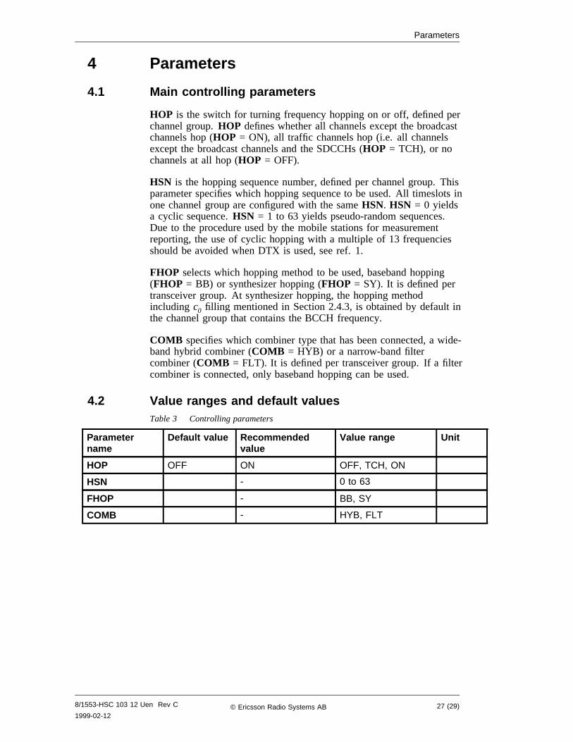
4 Parameters
4.1 Main controlling parameters
HOP is the switch for turning frequency hopping on or off, defined perchannel group.HOP defines whether all channels except the broadcastchannels hop (HOP = ON), all traffic channels hop (i.e. all channelsexcept the broadcast channels and the SDCCHs (HOP = TCH), or nochannels at all hop (HOP = OFF).
HSN is the hopping sequence number, defined per channel group. Thisparameter specifies which hopping sequence to be used. All timeslots inone channel group are configured with the sameHSN. HSN = 0 yieldsa cyclic sequence.HSN = 1 to 63 yields pseudo-random sequences.Due to the procedure used by the mobile stations for measurementreporting, the use of cyclic hopping with a multiple of 13 frequenciesshould be avoided when DTX is used, see ref. 1.
FHOP selects which hopping method to be used, baseband hopping(FHOP = BB) or synthesizer hopping (FHOP = SY). It is defined pertransceiver group. At synthesizer hopping, the hopping methodincluding c0 filling mentioned in Section 2.4.3, is obtained by default inthe channel group that contains the BCCH frequency.
COMB specifies which combiner type that has been connected, a wide-band hybrid combiner (COMB = HYB) or a narrow-band filtercombiner (COMB = FLT). It is defined per transceiver group. If a filtercombiner is connected, only baseband hopping can be used.
4.2 Value ranges and default valuesTable 3 Controlling parameters
Parametername
Default value Recommendedvalue
Value range Unit
HOP OFF ON OFF, TCH, ON
HSN - 0 to 63
FHOP - BB, SY
COMB - HYB, FLT
8/1553-HSC 103 12 Uen Rev C
1999-02-1227 (29)© Ericsson Radio Systems AB
Parameters
This page is intentionally left blank
28 (29) 8/1553-HSC 103 12 Uen Rev C
1999-02-12© Ericsson Radio Systems AB
References
5 References1 User Description, DTX.
8/1553-HSC 103 12 Uen Rev C
1999-02-1229 (29)© Ericsson Radio Systems AB
Related Documents