Installation and Servicing Instructions E-Tec 25R Wall Mounted, Fan Assisted, Room Sealed, Gas Fired, High Efficiency Condensing Regular Boiler Nepicar House, London Road, Wrotham Heath, Sevenoaks, Kent TN15 7RS For Technical help or for Service call ... ALPHA HELPLINE Tel: 0344 871 8764 website: www.alpha-innovation.co.uk Set for use with Natural Gas Leave these instructions with the User These instructions have been carefully prepared but we reserve the right to alter the specification at any time in the interest of product improvement. © Alpha Therm Limited 2018. Part No. 1.041526 rev. ST.003864/000 1118/D389

Welcome message from author
This document is posted to help you gain knowledge. Please leave a comment to let me know what you think about it! Share it to your friends and learn new things together.
Transcript

Installation and ServicingInstructions
E-Tec 25R
Wall Mounted, Fan Assisted, Room Sealed,Gas Fired, High Efficiency Condensing Regular Boiler
Nepicar House, London Road,Wrotham Heath, Sevenoaks,
Kent TN15 7RS
For Technical help or for Service call ...ALPHA HELPLINE Tel: 0344 871 8764
website: www.alpha-innovation.co.uk
Set for use with Natural Gas
Leave these instructions with the User
These instructions have been carefully prepared but we reserve the right to alter the specification at any time in the interest of product improvement.© Alpha Therm Limited 2018.
Part No. 1.041526 rev. ST.003864/0001118/D389

2 Alpha E-Tec 25R - Benchmark Scheme
BENCHMARK SCHEME
To comply with Building Regulations Part L1 (Part 6 in Scotland) the boiler should be installed in accordance with the manufacturer’s instructions. Self-certification that the boiler has been installed to comply with Building Regulations can be demonstrated by completing and signing the Benchmark Checklist at the back of these instructions.
Code of PracticeFor the installation, commissioning and servicing of domestic heating and hot water products.Benchmark places responsibilities on both manufacturers and installers*. The purpose is to ensure that customers** are provided with the correct equipment for their needs, that it is installed, commissioned and serviced in accordance with the manufacturer's instructions by competent persons and that it meets the requirements of the appropriate Building Regulations. Installers are required to carry out work in accordance with the following:
Standards of Work
• Be competent and qualified to undertake the work required.
• Install, commission, service and use products in accordance with the manufacturer's instructions provided.
• Ensure that where there is responsibility for design work, the installation is correctly sized and fit for purpose.
• Meet the requirements of the appropriate Building Regulations. Where this involves notifiable work be a member of a Competent Persons Scheme or confirm that the customer has notified Local Authority Control (LABC), prior to work commencing.
• Complete all relevant sections of the Benchmark Checklist/Service Record when carrying out commissioning or servicing of a product or system.
• Ensure that the product or system is left in a safe condition and, where possible, in good working order.
• Highlight to the customer any remedial or improvement work identified during the course of commissioning or servicing work.
• Refer to the manufacturer's helpline where assistance is needed.
• Report product faults and concerns to the manufacturer in a timely manner.
Customer Service
• Show the customer any identity card that is relevant to the work being carried out prior to commencement or on request.
• Give a full and clear explanation/demonstration of the product or system and its operation to the customer.
• Hand over the manufacturer's instructions, including the Benchmark Checklist, to the customer on completion of an installation.
• Obtain the customer's signature on the Benchmark Checklist to confirm satisfactory demonstration and receipt of manufacturer's instructions.
• Advise the customer that regular product servicing is needed, in line with manufacturers' recommendations, to ensure that safety and efficiency is maintained.
• Respond promptly to calls from a customer following completion of their work, providing advice and assistance by phone and, if necessary, visiting the customer.
• Rectify any installation problems at no cost to the customer during the installer's guarantee period.
* The use of the word "installer" is not limited to installation itself and covers those carrying out installation, commissioning and/or servicing of heating and hot water products, or the use of supporting products (such as water treatment or test equipment).
** Customer includes householders, landlords and tenants.
Benchmark Commissioning and Servicing SectionIt is a requirement that the boiler is installed and commissioned to the manufacturers instructions and the data fields on the commissioning checklist completed in full.
To instigate the boiler guarantee the boiler needs to be registered with the manufacturer within one month of the installation.
To maintain the boiler guarantee it is essential that the boiler is serviced annually by a Gas Safe registered engineer who has been trained on the boiler installed. The service details should be recorded on the Benchmark Service Interval Record and left with the householder.
Useful contact details: Gas Safe Register - 0800 408 5577 - www.gassaferegister.co.uk
Alpha Heating Innovation: General Sales Enquiries - 0344 871 8760 Technical Helpline - 0344 871 8764
www.centralheating.co.uk
3
CONTENTS
1 Introduction ........................................3
2 Safety symbols ..................................4
3 Technical data ...................................5
4 General boiler information .................9
5 Installation .........................................16
6 Commissioning ..................................26
7 Routine servicing ...............................33
8 Component replacement ...................37
9 Wiring diagram ..................................40
10 Error codes and fault finding..............41
11 Short parts list ...................................43
12 Energy classification ..........................44
Benchmark Checklist .........................50
Service Record ..................................51
The E-Tec R is a wall mounted, room sealed, fan assisted, high efficiency, condensing boiler. The burner is lit electronically and the heat output is controlled by a modulating fan and gas valve.
The E-Tec R is a boiler that provides heating only on a fully pumped open vented system or with the addition of a sealed system kit, a sealed heating system.
IMPORTANTFailure to install and commission this appliance in compliance with the manufacturer's instructions may invalidate the warranty.
It is the law that all gas appliances are installed by a competent person, ie Gas Safe registered personnel, in accordance with the following recommendations:-Current Gas Safety (Installation and Use) RegulationsAll current Building Regulations issued by the Department of the Environment, i.e. Approved Document L26.Building Standards (Scotland) (Consolidation) Regulations issued by the Scottish Development DepartmentUK Water Regulations/Byelaws (Scotland)Health & Safety Document No. 635 (The Electricity At Work Regulations 1989)The installation should also be in accordance with the following British Standard Codes of Practice:-
BS 5440-1: 2008 ........................Flueing and Ventilation Requirements BS 5440-2: 2009 ........................Installation and Maintenance of Flues and VentilationBS 5546: 2010 ...........................Specification for Water Heating AppliancesBS 6798: 2009 ...........................Specification for Installation gas fired boilers up to 70 kWBS 6891: 2005 + A2: 2008 .........Installation of low pressure Gas PipeworkIGEM/UP/2 ...............................Installation of pipeworkIGEM/UP/4 ................................Commissioning of gas fired plantIGE/UP/10 .................................Installation of Flued gas appliancesIGEM/UP/16 ..............................Design for natural gas installationsIGE/UP/1 and 1B .......................Strength Testing and tightness testing Natural Gas Installations
Reference should also be made to any other standards and requirements relating to the installation depending on the location and use.Reference should be made to DEFRA document 'Guide to condensing boiler installation assessment procedures for dwellings'.If installation is in a timber framed building, refer to the Institute of Gas Engineers document IGE/UP/7.This appliance meets the requirements of IPX5D, ie degree of protection against moisture.This appliance contains no asbestos and no substances have been used in the construction process that contravene the COSHH Regulations (Control of Substances Hazardous to Health).Failure to install this appliance correctly could lead to prosecution. It is in your own interest and that of safety to ensure that the law is complied with.Manufacturer's instructions must NOT be taken in anyway as over-riding statutory obligations.Notes: 1. Ensure that the Benchmark Checklist has been completed after the boiler has been installed and commissioned. 2. It is the law that all domestic boiler installations are registered by the installer through the Gas Safe Notification
Scheme. 3. The boiler must only be used with Alpha CD condensing flue components.
Propane Gas (LPG) - In addition to the regulations and requirements stated, the boiler must be installed in accordance with BS 5482:1 - The Installation of Propane Burning Appliances in Permanent Dwellings.
1 INTRODUCTION
Alpha E-Tec 25R - Contents/Introduction
4
ELECTRICAL HAZARD
Strictly follow all of the indications next to the symbol. The symbol indicates the appliance’s electrical components or, in this manual, identifies actions that can cause an electrical hazard.
MOVING PARTS
The symbol indicates the appliance’s moving components that can cause hazards..
HOT SURFACES
The symbol indicates the appliance’s very hot components that can cause burns.
SHARP SURFACES
The symbol indicates the appliance’s components or parts that can cause cuts if touched.
EARTH TERMINAL CONNECTION
The symbol identifies the appliance’s earth terminal connection point.
READ AND UNDERSTAND THE INSTRUCTIONS
Read and understand the appliance’s instructions before performing any operation, carefully following the indications provided.
RECOVERABLE OR RECYCLABLE MATERIAL
INFORMATION
Indicates useful tips or additional information.
SAFETY GLOVES
SAFETY GOGGLES
SAFETY FOOTWEAR
The user must not dispose of the appliance at the end of its service life as municipal waste, but send it to appropriate collection centres.
GENERIC HAZARD
Strictly follow all of the indications next to the symbol. Failure to follow the indications can generate hazard situations resulting in possible harm to the health of the operator and user in general.
Alpha E-Tec 25R - Safety Symbols
2 SAFETY SYMBOLS
PERSONAL PROTECTIVE EQUIPMENT

5
3 TECHNICAL DATA
Alpha E-Tec 25R - Technical Data
Note: OtherTechnical data is the same as NG data.
* with Alpha Diverter Kit or DHW relay fitted
** Sealed system - Kit required
* with Alpha Diverter Kit or DHW relay fitted
3.2 TECHNICAL PERFORMANCE DATA - LPG - PROPANE GAS (Cat I3P 3P - G31 37 mbar)
Heat input gross - DHW* kW
Heat input gross - CH kW
Gas supply pressure mbar
Gas burner injector mm
CO2 at maximum CH output %
CO2 at maximum DHW output %
CO2 at minimum output %
Gas rate at maximum output kg/h (g/s)
31.3
26.7
37
3.80
11.4
11.4 (+0.1/-0.3)
10.6 (+0.3/-0.1)
2.24 (0.62)
E-Tec 25R
3.1 TECHNICAL PERFORMANCE DATA - NATURAL GAS (Cat I2H 2H - G20 20 mbar)
Heat input gross - DHW* kW
Heat input gross - CH kW
Heat input net - DHW* kW
Heat input net - CH kW
Heat output condensing (50/30°C) - CH kW
Heat output non condensing (80/60°C) CH kW
Heat output min. - CH kW
Heat output nominal - DHW* kW
Gas rate at max. output m³/h
Gas supply pressure mbar
Max. CH temperature - Set point °C
Gas burner injector diameter mm
Dry NOx weight (net calorific value) mg/kWh
Dry NOx ppm
NOx Class
Factory set CO2
CO2 at maximum CH output %
CO2 at maximum DHW output %
CO2 at minimum output %
CO (max) ppm
Maximum CO/CO2 Ratio
SAP/SEDBUK seasonality efficiency 2005 %
SAP/SEDBUK seasonality efficiency 2009 %
ErP Seasonal space heating efficiency %
Max. primary system pressure** bar (MPa)
Min. primary system pressure** bar (MPa)
Recommended system pressure - Cold** bar (MPa)
System pressure relief valve setting** bar (MPa)
Expansion vessel size** litres
Expansion vessel charge pressure** bar (MPa)
Electrical power consumption - Max. Watts
Electrical power consumption - Standby Watts
Max. temperature of combustion products °C
Max. flue overheating temperature °C
Category
Type of installation
E-Tec 25R
32.0
27.3
28.8
24.6
26.1
24.1
4.3
28.3
3.05
20
80
5.00
35
20
6
9.7
9.7 (+0.5/-0.2%)
8.8 (+0.2/-0.3%)
450
0.004
90.3
89
92
2.5 (0.25)
0.5 (0.05)
1.0 (0.1)
3.0 (0.3)
8.0
1.0 (0.1)
55
6
75
120
II 2H3P
C13, C33, C43, C53, C63, C83, C93

6 Alpha E-Tec 25R - Technical Data
3.4 FLUE LENGTHS
A 500 mm or 1000 mm Easy-Flue terminal kit with 90° bend or horizontal terminal is available.
CD 750 mm and 1000 mm flue extensions are available.
Length of Flue Required:-
Rear Flue = wall thickness + 163 mm (includes terminal).
Side Flue = wall thickness + distance between wall and side of boiler + 205 mm (left side) or 235 (right side)
(includes terminal).
Vertical Flue = distance from top of boiler side panel to required roof position minus 1000 mm for vertical terminal assembly.
Maximum horizontal flue length = 12 m.
Maximum vertical flue length including terminal is 14 m.
Each additional CD 90° Bend is equivalent to 1.3 m of flue length.
Each CD 45° Bend is equivalent to 0.9 m of flue length.
The CD Vertical Flue terminal assembly is equivalent to 1 m of flue length.
3.3 PHYSICAL DATA
Boiler flow and return connections mm
Gas connection diameter mm
Boiler dimensions Height mm
Width mm
Depth mm
Clearances for servicing Bottom mm
Top (horizontal flue) mm
Top (vertical flue) mm
Sides mm
Front mm
Recommended hole size for flue pipe mm
Recommended hole size for instalation from inside the building mm
Boiler dry lift weight kg
Boiler operating weight (full of water) approx. kg
Max. total flue length Horizontal m
Max. total flue length Vertical m
Flue system diameter mm
Ambient operating temperature °C
22
22
600
390
300
250
235
150
5
450
110
130
25
27
12
14
60/100
-5 min. 40 Max.*
* with frost protection enabled

7
Colour Code
Bk BlackBl BlueBr BrownG GreenGy GreyG/Y Green/YellowR RedW White
B4
M
When an Alpha Climatic control isconnected to terminals 41 and 44
remove the links between terminalblocks 1 and 2
Remove link toconnect 230 V
room thermostat
Mains Supply230 V ~ 50 Hz
230 V Roomthermostat(optional)
External pump(optional)
230 Vac Max 1 A
Programmer clock(optional)
Remove link toconnect clock
Bk
Bl
Br
Gy
W
(Hea
tin
g)
CH
1 -
DH
W O
FF
(DH
W O
N)
CH
2 -
CH
ON
(Co
mm
on
)
BrGYBr
BlW
Bl
BlBr
G/Y
G/Y
G/Y
Bk
Bk
Storage tankNTC probe(optional)
230 Vac DHWrequest signal
Diverter valve(optional)
Alpha Climatic(optional)
36 38 4137
6
5 39 44
G G W W Bk R
L N 1 2 3 4 L2 N2
Br
Br
Bl
Bl R
Bl Bk
R
G/Y
Ch 1
Ch 2
1 2
3
4
5
'230 Vac DHW request signal' is alternative to'Diverter valve' and Storage tank NTC probeX1
X2 NC COM NO
Relay board (optional)
X15 on PCB X3 on PCB X16 on PCB X12 on PCB X14 on PCB
COM
NO
Alpha E-Tec 25R - Technical Data
Note: This Appliance Must Be EarthedOptional integral controls are available if required.Note: Only use the Alpha two channel controls. Do not fit any single channel controls*.Fig. 3.1 shows the Internal two channel clock option for S or Y plan. Alternatively bring a Switched Live from external controls to terminal 1.DO Not connect an Alpha Climatic control when the proprogrammer clock is connected.
3.5 ELECTRICAL CONNECTIONS
Fig. 3.1
3.6 DATA BADGE ANNOTATION
MdSr No
TypeQnw/Qn min.
PMSNOx Class
Qnw/Qn max.
PMW
Cod. MdCod. PIN
Pn min.
DPn max.
TM
CONDENSING
Md.............................ModelCod. Md ....................Model codeSr No .........................Serial numberCHK ..........................CheckCod. PIN ...................PIN codeType ..........................Type of installation (ref. CEN TR 1749)Qnw min. .....................DHW minimum heat inputQn min. .......................CH minimum heat inputQnw max. ....................DHW maximum heat inputQn max. ......................CH maximum heat input
Pn min. .......................Minimum heat outputPn max. .......................Maximum heat outputPMS ..........................Maximum system pressurePMW .........................Maximum DHW pressureD ...............................Specific flow rateTM ............................Maximum operating temperatureNOx Class .................NOx ClassCONDENSING .........Condensing boiler
NOTE: Technical data is provided on the boiler data label and in Section 3.1.
* If the boiler is used for heating only a single channel control can be fitted.
Fit the clock or receiver as normal and connect a link between terminals L and 3 on the boiler.
8
3.7 BOILER SCHEMATIC
Fig. 3.2
Alpha E-Tec 25R - Technical Data
1 Gas isolation valve
2 Gas valve
3 Gas injector
4 Condensate trap
5 Venturi positive pressure point (+)
6 Primary flow sensor
7 Drain valve
8 Overheat thermostat
9 Ignition/sensing electrode
10 Air supply pipe
11 Flue temperature sensor and thermal fuse
12 Flue test point (pressure point +)
13 Air test point (pressure point -)
14 Condensing heat exchanger
15 Burner
16 Primary return sensor
17 Venturi
18 Fan
19 Drain valve
Gas
Condensate discharge
Primary
Heating
return
Primary
Heating
flow
1
2
3
4
5
6
7
8
9
10
11
12
17
19
16
18
15
14
13

9
4.1 GAS SUPPLY
The meter and supply pipes must be capable of delivering the required quantity of gas in addition to the demand from any other appliances connected to the same gas supply.Refer to Technical performance data in Section 3.1 and 3.2.The complete installation, including the meter, must be tested for gas tightness and purged as described in BS 6891.
4.2 ELECTRICAL SUPPLY
ATTENTION:
The power supply cable must be connected to a 230 V ±10% / 50 Hz mains supply respecting L - N polarity and earth connection; , this must be connected to a fused double pole switch with class III overvoltage category (contact separation of at least 3 mm in both poles) or a fused 3-pin plug and unswitched shuttered socket outlet (both complying with BS 1363) in compliance with installation regulations.
The boiler is supplied with a 'Special X' type electrical connection with a PVC <HAR> H05W-F 3 x 0.75 cable without a plug.
If the power cable is damaged or replaced, it must be replaced with a cable supplied by Alpha or authorized After-Sale Technical Service. Replacement is recommended using a qualified company in order to prevent any risk.
The boiler must be earthed.
There must only be one common isolator, providing complete electrical isolation, for the boiler and any external controls.
Wiring external to the boiler must be in accordance with the current IEE Wiring Regulations (BS 7671).
Note: If a room thermostat is fitted, it must be suitable for 230/240 V switching.
4.3 AIR SUPPLY
The boiler does not require any air vents for cooling in the room in which it is installed or when installed in a cupboard or compartment. The minimum clearances for servicing must always be maintained.
Note: A cupboard or compartment used to enclose the boiler must be designed and constructed specifically for the purpose, i.e. comply with the Building Regulations.
4.4 FLUE SYSTEM - Figs. 4.1, 4.2
The flue system must be installed in accordance with BS 5440:1.
When using a horizontal flue kit ensure that the flue outer duct is installed horizontally (please note that the flue inner duct already has a pre-determined slope towards the boiler for condensate to run back towards the boiler).
When additional flue extensions are used, ensure the flue slopes downwards towards the boiler by a minimum of 25 - 30 mm per metre of flue.
Horizontal and vertical flue assemblies should be supported every metre with access provided to the joints.
Additional flue components are available as follows:-
CD EasyFlue 500 mm telescopic terminal - Part No. 6.12000510.
CD EasyFlue 1000 mm telescopic terminal - Part No. 6.12001010.
CD 750 mm flue extension - Part No. 6.2000750.
CD 1000 mm flue extension - Part No. 6.2001050.
CD 100 mm flue support brackets (pack of 5) - Part No. 6.1000355.
CD 90° bend - Part No. 6.2000590.
CD 45° bend - Part No. 6.2000545.
CD Vertical flue terminal kit - Part No. 6.2000520. Refer to the separate installation instructions supplied with the kit.
Flue support brackets - Part No. 6.1000355.
Terminal guard - Part No. 6.2000570.
Additional flue accessories and plume management are also available.
Note: 1. If an extra 90° bend is used, this reduces the maximum flue length by 1.3 m. Each 45° bend used reduces the maximum flue length by 0.9 m.
2. Under no circumstances must the flue length (including allowances for extra bends) exceed 12 metres horizontally and only 14 metres vertically.
3. Failure to use Alpha flue components with the boiler will invalidate the boilers CE approval, guarantee and may be unsafe.
4 GENERAL BOILER INFORMATION
Alpha E-Tec 25R - General Boiler Information

10
L = A + B = 12m max.
Alpha E-Tec 25R - General Boiler Information
L = A + B + (90° bend = 1.3 metre)
L = A + (2 x 45° bends = 1.8 metre)
Fig. 4.2
VERTICAL FLUE OPTIONS
Hmax = 14 m Hmax = 12.2 m (14 m - 1.8 m)
12 m
B
A
A
B
A
HORIZONTAL FLUE OPTIONS - Lmax - 12 metres
Not less than
300 mm
H
Not less than
300 mm
H
Fig. 4.1
11
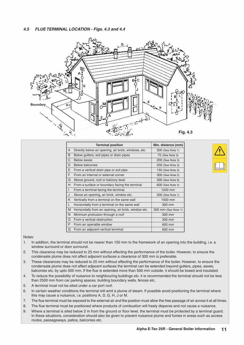
4.5 FLUE TERMINAL LOCATION - Figs. 4.3 and 4.4
Notes:1. In addition, the terminal should not be nearer than 150 mm to the framework of an opening into the building, i.e. a
window surround or door surround.2. This clearance may be reduced to 25 mm without effecting the performance of the boiler. However, to ensure the
condensate plume does not affect adjacent surfaces a clearance of 300 mm is preferable.3. These clearances may be reduced to 25 mm without effecting the performance of the boiler. However, to ensure the
condensate plume does not affect adjacent surfaces the terminal can be extended beyond gutters, pipes, eaves, balconies etc. by upto 500 mm. If the flue is extended more than 500 mm outside, it should be boxed and insulated.
4. To reduce the possibility of nuisance to neighbouring buildings etc. it is recommended the terminal should not be less than 2500 mm from car parking spaces, building boundary walls, fences etc.
5. A terminal must not be sited under a car port roof.6. In certain weather conditions the terminal will emit a plume of steam. If possible avoid positioning the terminal where
this may cause a nuisance, i.e. positions A, D, G, H, J or M.7. The flue terminal must be exposed to the external air and the position must allow the free passage of air across it at all times.8. The flue terminal must be positioned where products of combustion will freely disperse and not cause a nuisance.9. Where a terminal is sited below 2 m from the ground or floor level, the terminal must be protected by a terminal guard.
In these situations, consideration should also be given to prevent nuisance plume and fumes in areas such as access routes, passageways, patios, balconies etc.
Alpha E-Tec 25R - General Boiler Information
A Directly below an opening, air brick, windows, etc.
B Below gutters, soil pipes or drain pipes
C Below eaves
D Below balconies
E From a vertical drain pipe or soil pipe
F From an internal or external corner
G Above ground, roof or balcony level
H From a surface or boundary facing the terminal
I From a terminal facing the terminal
J Above an opening, air brick, window etc.
K Vertically from a terminal on the same wall
L Horizontally from a terminal on the same wall
M Horizontally from an opening, air brick, window etc.
N Minimum protrusion through a roof
O From a vertical obstruction
P From an openable window
Q From an adjacent vertical terminal
Min. distance (mm)Terminal position
300 (See Note 1)
75 (See Note 3)
200 (See Note 3)
200 (See Note 3)
150 (See Note 3)
300 (See Note 2)
300 (See Note 9)
600 (See Note 4)
1200 mm
300 (See Note 1)
1500 mm
300 mm
300 mm (See Note 1)
300 mm
300 mm
600 mm
600 mm
J
D
G
H I
Q
Boundary
O P
N
Fig. 4.3

12
Proximity of flue duct outlets to boundaries
The flue duct shall be sited so that it is at least 600 mm (see Fig. 4.4) from the boundary line when facing it and at least 300 mm from the boundary line when running parallel to it.
Fig. 4.4
600 mm
2000 mm600 mm300 mm
300 mm
Terminal facing the boundary
Terminal facing an opening
in adjacent building
Terminal at an angle to the boundary
Terminal parallel to the boundary
Boundary
Boundary
Boundary
Boundary
Terminal
Terminal
Terminal
Terminal
Building Building
Building
Building
Adjacent building
Window
4.6 BOILER LOCATION
The boiler is not suitable for external installation unless it is installed within a purpose designed weatherproof building.The boiler must be installed on a flat vertical wall which is capable of supporting the weight of the boiler. The boiler can be fitted to or adjacent to a wall comprising of a combustible material without the need for a special thermal insulation barrier.If the boiler is to be fitted in a timber framed building, it should be fitted in accordance with the Institute of Gas Engineers 'Guide for Gas Installations in Timber Frame Housing', reference IGE/UP/7.
The boiler may be installed in any room or internal space, although particular attention is drawn to the requirements of the current IEE Wiring (BS 7671) Regulations, and in Scotland, the electrical provisions of the Building Regulations applicable in Scotland, with respect to the installation of the boiler in a room or internal space containing a bath or shower. Where a room-sealed boiler is installed in a room containing a bath or shower, it must not be possible for a person using the bath or shower to touch any electrical switch or boiler control utilising mains electricity.
The boiler may be installed in a cupboard or compartment, provided it is correctly designed for that purpose, i.e. complies with the Building Regulations and the requirements of BS 6798.
Alpha E-Tec 25R - General Boiler Information

13
4.7 CENTRAL HEATING SYSTEM - Figs. 4.5 and 4.6
The boiler is designed for use in an open or (if the alpha sealed system kit is used) sealed central heating system in accordance with the requirements of BS 5449 and BS 6798. The external pump must be able to achieve a minimum flow rate of 900 l/m on open systems or 515 l/m on sealed systems.
Alpha E-Tec 25R - General Boiler Information
Fig. 4.5 - Open system with Y-Plan
Fig. 4.6 - Sealed system with Y-Plan
4.8 FILLING THE OPEN VENTED CENTRAL HEATING SYSTEM
A minimum head of 1 m is required between the boiler/pump and the feed and expansion tank.
The boiler must be supplied from an unrestricted water supply taken from a feed and expansion cistern situated at a maximum height of 27 m above the boiler.
The cold feed must be 15 mm minimum size. The vent should be 22 mm in size, rise continuously and be unrestricted.
It is important that the relative positions of the pump, cold feed and open vents are as shown in Fig. 4.5.
The domestict hot water cylinder must be of the fully indirect coil type.
Boiler
150mm max
1000mm min height
Feed andexpansion tank
Vent (22mm min)
Cold feed(15mm min)
Pump
DHW storagecylinder
Mid position 3-port valveor Alpha diverter valve
with cylinder sensor
Automaticby-pass valve Balancing
valve
450mm min height
Magnetic type filterrecommended
Pump
Boiler
DHW storagecylinder
Automaticby-pass valve Balancing
valve
Manual air vents
Pressure gauge
Expansion vesselDischarge
pipe
Filling point
Mid position 3-port valve orAlpha diverter valvewith cylinder sensor
Magnetic type filterrecommended
Expansionvalve

14
4.10 FLUSHING THE HEATING SYSTEM
It is essential that the central heating system is thoroughly cleaned and flushed before fitting an Alpha E-Tec R boiler. Failure to do so will invalidate the warranty. The primary condensing heat exchanger is constructed in stainless steel and therefore is compatible with most materials used in a heating system.
Where possible, the heating system should be cleaned before installing the boiler. A proprietary cleaner should be used following the product manufacturers' instructions. After installation the system should then be filled and flushed before final filling. A corrosion inhibitor approved by Alpha must be added to ensure that the heating system operates effectively and efficiently, it is important to maintain the correct level of corrosion inhibition at all times.
The corrosion inhibitor should be checked annually at the time of the boiler service, and topped up if necessary. A further dose of corrosion inhibitor should be added to the system every five years.
It is important to ensure that the correct level of inhibitor has been added, and that any cleaner residues have been adequately removed to maintain the operation of the boiler and heating system. Failure to correctly clean and treat the system will invalidate the boiler warranty.
If it is not possible to clean the system before fitting the new boiler, the system should be cleaned using a proprietary cleaner and a magnetic filter connected in the return before the boiler as this is the most effective method of ensuring that any magnetite and rust particles are prevented from entering and damaging the boiler.
Once the system condition has been restored, an effective magnetic filter and strainer should be fitted permanently to the system as a method of collecting any magnetite and rust from the system during operation.
4.11 DISPOSAL OF CONDENSATE
Provision must be made for the safe disposal of condensate produced by the flue gases of the Alpha boilers and reference should be made to BS 6798 for the requirements on the disposal of condensate.
The boilers incorporate a condensate trap which has a seal of greater than 75 mm, therefore no additional trap is required.
The condensate should ideally be discharged internally into an internal waste pipe (washing machine/sink waste) or soil pipe to avoid the possible risk of freezing. The pipework must be in 22 mm pipe (minimum).
External pipe runs should be avoided, but if it is necessary, the pipework should be protected from the risk of freezing with waterproof insulation and the length should be kept to a maximum of 3 m and the condensate pipework should be increased to a minimum of 32 mm diameter. Termination should be into an external gulley or soakaway as shown in Figs. 4.9 and 4.10.
Note: All pipework must have a continuous fall (see Figs. 4.9 and 4.10) from the boiler and must be of an acid resistant material such as plastic waste pipe. (copper or steel is not suitable).
The condensate pipe is combined with the expansion relief discharge. The flexible condensate hose supplied meets the requirements for use with both condensate and expansion relief. This should be connected to a suitable waste pipe and fittings with approval for hot and cold water, i.e. BS EN1451-1PP Waste piping, BS EN1455-1 ABS piping or BS EN 1566-1 MUPVC piping.
The condensate and discharge should be connected to a drain for sewage and foul waste or a dedicated soak away with neutraliser added.
It should be noted that the connection of a condensate pipe to a drain may be subject to local building control requirements.
Alpha E-Tec 25R - General Boiler Information
Fig. 4.7 Fig. 4.8
Filling looptemporarily connected
Heating circuit return
Mains water supplyStop
valve
Hose unions
Stop valve
Double check valve assembly
Test cock
Feed cistern to be located above highest point in the system
Mains water supply
Stop valve
Test cock
Double check valve assembly
Overflow
Heating circuit return
4.9 FILLING THE SEALED CENTRAL HEATING SYSTEM - Figs. 4.7 and 4.8
The system design pressure (cold) should be set to 1.0 bar. This pressure is equivalent to a static head (see Fig. 4.5) of 10.2 metres of water.Provision should be made to replace water lost from the system. This can be by manual or automatic means, as shown in Figs. 4.7 and 4.8. The position for connecting an automatic make-up vessel is indicated in Fig. 4.6. A double check valve assembly must be used, as shown in Fig. 4.8.Filling of the system must be carried out in a manner approved by the local Water Undertaking. Where allowed, the system may be filled via a temporary connection as shown in Fig. 4.7. After filling, always disconnect the flexible hose of the filling loop.All fittings used in the system must be able to withstand pressures up to 3 bar.Drain taps (to BS 2879) must be used to allow the system to be completely drained.

15Alpha E-Tec 25R - General Boiler Information
Fig. 4.9 - External gully
Open end of pipe
diverted into gully
below grid but above
water level
Use waterproof
pipework insulation
in very exposed
positions
Ensure pipe is
adequately supported
Plastic pipe
(minimum 32 mm)
Minimum gradient 2½°
Fig. 4.10 - External soakaway
Ground level (either/or)
22mm termination from boiler, increase to 32 mm if external
2½ fallO
25mm
300mm
Two rows of 3 x 12mm
holes at 25mm centres,
50mm from the bottom
of the tube. Holes to face
away from house.
Cement mortar sealing
100mm plastic tube
Bottom of tube sealed
Soakaway depth 400mm
filled with limestone chippings
500 mm min.

16
5.3 PREPARE THE WALL - Fig. 5.2
1. Decide upon the position of the boiler taking into account the clearances required for servicing and the flue terminal position.
2. Tape the template to the wall (ensure it is level and the right way up) and mark the position of the holes for the boiler mounting bracket. If rear exit flue is used, mark the position of the hole for the flue.
3. Side exit flue - Continue the horizontal centre line of the flue across the wall to the side wall, then along the side wall 138 mm (ensure the lines are horizontal). This will give the position of the centre of the hole for the flue.
4. Cut the 110 mm diameter hole (or use a 107 mm core drill) in the wall for the flue.
Notes: 1. Ensure the hole is horizontal. 2. For internal fitting of the flue, using the flue sealing
collar supplied, cut a 130 mm dia. flue hole using a 127 mm core drill.
5. Drill the fixing holes (10 mm dia.) to accept the No.10 plugs supplied. Using the screws supplied, fit the mounting bracket.
5 INSTALLATION
Fig. 5.1
Alpha E-Tec 25R - Installation
5.1 UNPACKING
1. The boiler carton also contains the following:-
Connection kit (union bends, washers and gas service cock)
Mounting bracket plus screws and wall plugs
Condensate discharge pipe
Literature pack and Wall template
A suitable Alpha flue system must be selected to use with the boiler.
Notes: a. All flues must be suitable for Alpha condensing boilers. b. CD 750 mm and 1000 mm flue extensions are available, if required.Damaged products must not be used.
2. Unpack boiler and remove the loose items, packs and mounting bracket.
Note: The boiler can be stood in an upright position (only while the valves and union bends are not fitted).
It is recommended that two persons lift the boiler.
5.2 CLEARANCES REQUIRED - Fig. 5.1
Fig. 5.2
Minimum clearances
5 mm 5 mm
250 mm
390 mm
235 mm - Can be reduced to150 mm when using avertical flue
600 mm
Minimumclearanceof 450 mmfrom frontof boiler
300 mm
Template
Outline ofboiler
138 mmEnsure line is levelRear exit hole110 mm dia.
Position of110 mm holeto be cut forside exit flue
141 mm
Boiler bottomfixing holes
Fixing holesfor mountingbracket
HEATING
FLOW
(22 mm)
HEATING
RETURN
(22 mm)
IF SIDE FLUE EXIT:
110 mm (4.3 in) MIN FLUE HOLE DIAMETER
C/L OF FLUE MINIMUM TOP CLEARANCE
TOP OF CASING
MINIMUM SIDE
CLEARANCE 5 mm
BOILER
MOUNTING BRACKET
FIXING HOLES
BOTTOM BRACKET
FIXING HOLES
BOTTOM OF CASING
GAS
(22 mm)
MINIMUM BOTTOM
CLEARANCE 250mm
CONTINUE CENTRE LINE HORIZONTALLY ACROSS WALL
TO SIDE WALL. THEN HORIZONTALLY ALONG SIDE WALL
138 mm. THIS WILL GIVE CENTRE OF HOLE FOR FLUE.
ENSURE THE FLUE EXTENSION(S) SLOPE DOWN
TOWARDS THE BOILER BY A MINIMUM OF 25 - 30mm
PER METRE OF FLUE EXTENSION(S) USED.
HORIZONTAL FLUE 235mm
VERTICAL FLUE 150mm

17Alpha E-Tec 25R - Installation
5.4 FIT THE BOILER - Refer to Figs. 5.2 and 5.3
Lift the boiler and locate it on the mounting bracket - the boiler should be lifted by two persons.
Note: When handling or lifting always use safe techniques - keep your back straight, bend your knees, don't twist - move your feet, avoid bending forwards and sideways and keep the load as close to your body as possible.Where possible transport the boiler using a sack truck or other suitable trolley.Always grip the boiler firmly, and before lifting feel where the weight is concentrated to establish the centre of gravity, repositioning yourself as necessary.
5.5 CONNECT THE PIPEWORK - Fig. 5.4
1. Thoroughly flush out all the water pipework. Refer to Section 4.10.
2. Fit the gas service cock to the boiler connection in Fig. 5.4.
3. Connect the system pipework to the union fittings on the top of the boiler, see Fig. 5.4.
Note: When soldering bends, ensure they are not connected to the valves, otherwise the internal seals may be damaged.
One metre of copper pipe must be fitted to the boiler before connecting to any plastic pipework conforming to BS 7291.
4. Connect the flexible condensate pipe to the rubber connector as shown in Fig. 5.4. Using the adaptor supplied, connect the flexible pipe to the condensate drain.
Ensure that the condensate discharge pipe is as required in Section 4.10.
5. Ensure that the gas service cock is closed (operating lever at right angle to valve) and do not turn on the water or gas supplies at this stage.
Fig. 5.4
Fig. 5.3 - rear of boiler
Location forwall mountingbracket onrear of boiler
Pour water into flue duct(to fill condensate trap)
Heating return(22 mm)
Heating flow(22 mm)Gas service cock
HF R
Electrical connection
65
30
Bottom view
Top viewWall
Wall
27
28 55
Condensatedischarge pipe
Gas inlet (22 mm)Use compression
fittings

18
5.6 FIT THE FLUE - Figs. 5.5 and 5.6
The following procedure applies to fitting an Alpha CD Easy-Flue to both rear or side exit flue - horizontally only.
Alpha E-Tec 25R - Installation
2. Determine the overall length (L) of flue required, (see Fig. 5.7) as follows:-
Rear flue L = wall thickness (B) + 45 mm Side flue L = wall thickness (B) + distance between boiler and wall (C) + 115 mm (right side exit) or 85 mm (left side exit)
Fig. 5.7
Fig. 5.5 Fig. 5.6
CD
Easy-Flue
500 mm
1000 mm
B (mm)
Max
470
990
Min
330
790
(B)
Rear
Flu
e
(B + C)
Side Flue
Seal Joint with Tape
L
1. The CD Easy-Flues are suitable for use in the flue length ranges shown in the tables below.
Note: Where the length is less than the minimum or more than the maximum, refer to Section 5.7.
3. Adjust the telescopic section of the flue to the distance ‘L’, ensuring that the two labels marked ‘TOP’ are aligned, then seal and secure the joint between the ducts with the sealing tape supplied.
Note: Always ensure that there is a minimum overlap of 25 mm when fully extending the telescopic section.
4. Pass the flue assembly through the wall (from inside or outside). Note: Internal fitting - If there is no access to make good the outside wall, locate the outside (black) flue sealing collar
onto the outer duct of the flue immediately before the terminal grille onto the location provided. Push the flue assembly through the 130 mm flue hole, so that the collar completely passes through the wall. Then pull the flue assembly back into the correct position. Visually check that the collar is sealing the outside wall and that it is not restricting any of the openings of the flue terminal.
Note: Silicone grease or other lubricants must not be used on the flue joints or seals.
Where a flue terminates less than 150 mm below a gutter, eaves or other obstructions it is possible to extend the flue to allow the flue termination to clear the obstruction, providing the flue is not extended beyond the first joint. For situations below balconies or large eaves where extensions may be required, the flue must be supported using the correct brackets. Alternatively plume management components can be used with supports where necessary.
CD
Easy-Flue
500 mm
1000 mm
Max
475
920
Min
260
720
B + C (mm)
Right exit
Max
505
950
Min
290
750
B + C (mm)
Left exit
19Alpha E-Tec 25R - Installation
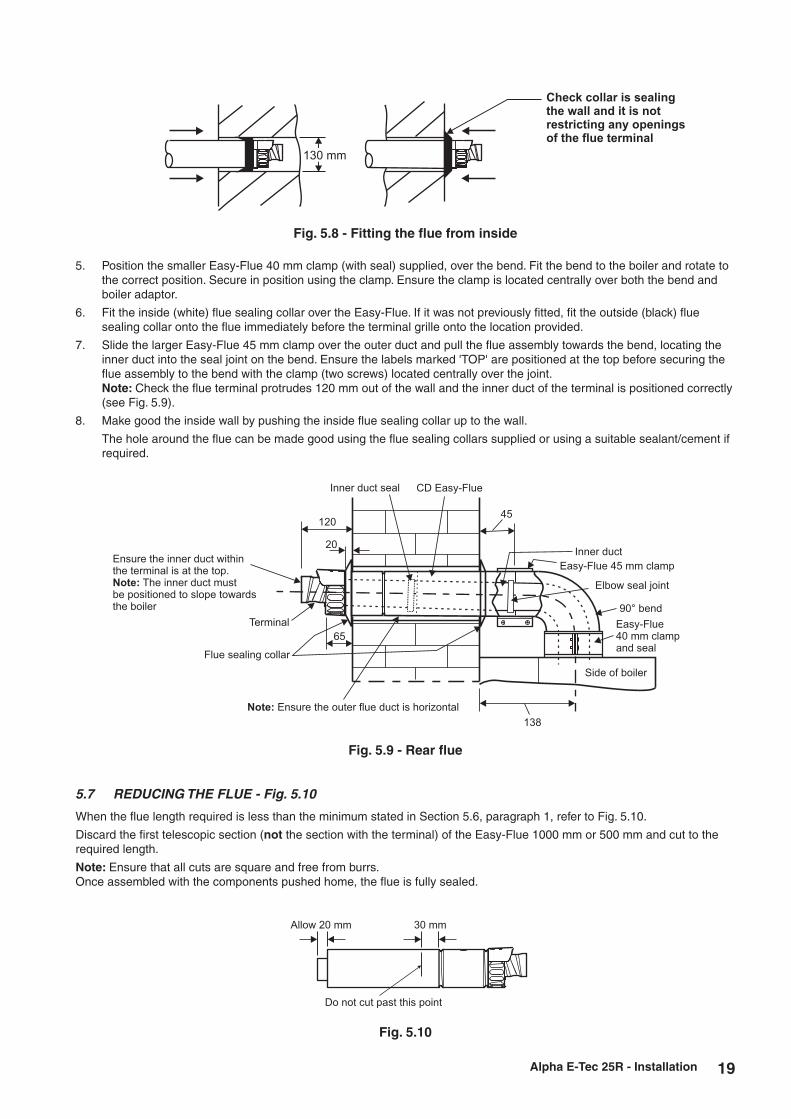
5. Position the smaller Easy-Flue 40 mm clamp (with seal) supplied, over the bend. Fit the bend to the boiler and rotate to the correct position. Secure in position using the clamp. Ensure the clamp is located centrally over both the bend and boiler adaptor.
6. Fit the inside (white) flue sealing collar over the Easy-Flue. If it was not previously fitted, fit the outside (black) flue sealing collar onto the flue immediately before the terminal grille onto the location provided.
7. Slide the larger Easy-Flue 45 mm clamp over the outer duct and pull the flue assembly towards the bend, locating the inner duct into the seal joint on the bend. Ensure the labels marked 'TOP' are positioned at the top before securing the flue assembly to the bend with the clamp (two screws) located centrally over the joint.
Note: Check the flue terminal protrudes 120 mm out of the wall and the inner duct of the terminal is positioned correctly (see Fig. 5.9).
8. Make good the inside wall by pushing the inside flue sealing collar up to the wall.
The hole around the flue can be made good using the flue sealing collars supplied or using a suitable sealant/cement if required.
Fig. 5.8 - Fitting the flue from inside
Check collar is sealingthe wall and it is notrestricting any openingsof the flue terminal
130 mm
Fig. 5.9 - Rear flue
Allow 20 mm 30 mm
Do not cut past this point
Fig. 5.10
5.7 REDUCING THE FLUE - Fig. 5.10
When the flue length required is less than the minimum stated in Section 5.6, paragraph 1, refer to Fig. 5.10.
Discard the first telescopic section (not the section with the terminal) of the Easy-Flue 1000 mm or 500 mm and cut to the required length.
Note: Ensure that all cuts are square and free from burrs.Once assembled with the components pushed home, the flue is fully sealed.
120
Inner duct
Elbow seal joint
90° bend
Easy-Flue40 mm clampand seal
Easy-Flue 45 mm clamp
Terminal
Flue sealing collar
Note: Ensure the outer flue duct is horizontal
Side of boiler
CD Easy-Flue
Ensure the inner duct withinthe terminal is at the top.
The inner duct mustNote:
be positioned to slope towardsthe boiler
20
65
Inner duct seal
45
138

20 Alpha E-Tec 25R - Installation
Easy-Flue 45 mm clamp
Easy-Flue40 mm clampand seal
45
Front of boiler
Extension clamp
Inner seal joint
Inner seal joint
Flue length (L)
90° bend
Seal joint
CD Easy-Flue
Ensure outer flue duct of Easy-Flue is horizontal
Ensure the flue extension slopesdownwards towards the boiler by aminimum of 25 - 30 mm per metre
CD Flue extension
Flue sealingcollar
Ensure the inner duct within the terminal is at the top.The inner duct must be positioned to slope towards the boilerNote:
120
Terminal
20
115
180 210
Fig. 5.11 - Side flue
5.8 EXTENDING THE FLUE - Fig. 5.11
Note: The flue assembly length must not exceed the maximum length stated, including the equivalent lengths of any extensions, bends etc. used for plume management components. E-Tec boilers must not exceed the maximum of an equivalent horizontal flue length of 12 m.
1. When the flue length required is more than the maximum stated in Section 5.6, paragraph 1, refer to the table below and Figs 5.5 and 5.6. Alpha CD 750 mm flue extension (Part No. 6.2000750) or 1000 mm extension (Part No. 6.2001050) is required to extend the range of telescopic flue.
Refer to Section 5.8 for instructions on how to extend the flue.
Note: A 130 mm flue hole (127 mm core drill) may be required in the wall. This is when the extended flue is passed through the wall.
Additional support brackets are required when extending the flue. These are available from Alpha, Part No. 6.1000355.
2. Use the template (supplied with the boiler) to mark the required flue position, ensure the slope towards the boiler is correct.
3. Determine the overall flue length as described in Section 5.6, paragraph 2 to determine the number of Alpha CD 750 or 1000 mm flue extensions required.
4. Assemble the flue extensions together by locating the inner duct into the seal joint and secure each extension together with the extension clamps supplied (three screws). Ensure that the clamps are positioned centrally over the joints.
Note: If it is required to cut an extension, DO NOT cut the end of the inner duct that incorporates the seal joint. Ensure the inner duct end without the seal joint is cut so that it is 20 mm longer than the outer duct.
Ensure that all cuts are square and free from burrs. Once assembled with the components pushed home, the flue is fully sealed.
5. Adjust the telescopic section of the Easy-Flue to the required length and secure the Easy-Flue with the sealing tape supplied. Fit the Easy-Flue to the extensions by locating the inner duct into the seal joint and secure with the clamp (three screws), ensuring it is located centrally over the joint.
6. Mark the end of the flue assembly 'TOP' where it is connected to the boiler, so that the 'TOP' of the flue terminal is aligned with the 'TOP' at the boiler end of the flue assembly.
7. Pass the complete flue assembly through the wall.
8. Position the smaller Easy-Flue 40 mm clamp (with seal) supplied, over the bend. Fit the bend to the boiler and rotate to the correct position and secure in position. Ensure the seal is located centrally over both the bend and boiler adaptor. If the inside sealing collar (white) is being used to make good the inside wall, then it will need to be fitted before assembling the flue.
9. Slide the larger Easy-Flue 45 mm clamp (two screws) over the outer duct and pull the flue assembly towards the bend, locating the inner duct into the seal joint on the bend.

21Alpha E-Tec 25R - Installation
Fig. 5.12
1
1
2
10. Secure the flue assembly to the bend with the clamp ensuring it is positioned centrally over the joint, ensuring the ‘TOP’ marked on the outer duct is positioned at the top.
Note: Check the flue terminal protrudes 120 mm out of the wall and that the inner duct of the terminal is positioned correctly, i.e. the inner duct within the terminal is at the top. See Fig. 5.11.
11. Make good the outside wall by fitting the outside sealing collar (black) onto the location provided immediately behind the flue terminal grille. Make good the inside wall using the inside sealing collar (white) if required.
5.9. FIT PLUME MANAGEMENT COMPONENTS - (OPTIONAL)
The following procedures detail the options for management of the exhaust flue gas/plume emitted from the terminal.
a. The terminal supplied with the Easy-Flue can be altered to divert exhaust flue gas/plume at an angle.
This can be achieved by simply turning the end section of the terminal to the desired angle.
b. The CD Easy-Flue can be converted to allow the inner flue duct to be extended so as to position the terminal in an area where the exhaust flue gas/plume will not cause a nuisance. This can be done before or after installation of the flue, providing there is access to the terminal from outside.
i. Remove the screws (1 in Fig. 5.12) securing the terminal and remove the terminal by pulling it from the flue assembly. Remove the screw (2 in Fig. 5.12) securing the terminal end section and remove the end section from the terminal.
ii. Locate a 93° Plume Management bend into the flue assembly and rotate it to the direction required. iii. Connect to the 93° bend the required Plume Management components as detailed and refer to Fig. 5.13. Notes: 1. The wall support brackets must be used to secure the Plume Management pipework to the wall and
prevent disconnection of the 93° bend from the flue assembly or any other component. 2. Each joint must be secured with one of the screws provided to prevent accidental disconnection. 3. Ensure there is always a slight slope towards the flue assembly fitted in the wall and there is no part
of the plume management pipework where condensate/rain will collect and cause a blockage or any restriction.
iv. Terminate the Plume Management pipework by fitting the terminal end section (push-fit) previously removed. Refer to Fig. 5.13.
v. The Plume Management components available for extending the inner flue duct are as follows:-
Plume Management 93° bend 60 mm dia. (each 93° bend equivalent to 1.3 m flue length) - Part No. 6.2001390. Plume Management 45° bend 60 mm dia. (each 45° bend equivalent to 0.9 m flue length) - Part No. 6.2001345. Plume Management 1000 mm extension 60 mm dia. (equivalent to 1 m flue length) - Part No. 6.2001310. 60 mm dia. wall bracket - Part No. 6.2001260. Plume kit (2 x 93° bends 1 x 1000 mm extension and wall bracket) - Part No. 6.2001300.

22 Alpha E-Tec 25R - Installation
PM length = C + (1 x 93° bend = 1.3 m) + (2 x 45° bends = 1.8 m)
C
Min.
400 mm
CD Easy-Flue
Flue sealing collar
Terminal end section
from CD Easy-Flue
PM length = C + (2 x 93° bend = 2.6 m) + (2 x 45° bends = 1.8 m)
C
Terminal end section
from CD Easy-Flue
PM length = C + (4 x 93° bend = 5.2 m)
C
Terminal end section
from CD Easy-Flue
Ensure there is a slope of approximately
3° back towards the Easy-Flue
Fig. 5.13
Note: The equivalent horizontal flue assembly length + the equivalent plume management length (PM length) must not exceed the maximum flue length stated for each boiler, i.e.
E-Tec boilers - the maximum equivalent flue length must not exceed 12 metres.
Note:
1. Ensure each joint is secured with the screw supplied.
2. Ensure there is always a slight slope towards the CD Easy-Flue so that there is no part of the pipework where condensate will collect.

23Alpha E-Tec 25R - Installation
5.10 CONNECT THE MAINS SUPPLY - Fig. 23
1. Gain access to the boiler terminal block by removing one screw at the top centre of the front panel, then lift up and remove panel. Release the two fixing screws (one each side) securing the control panel. Lower the control panel. See Fig. 7.1.
Refer to Technical Data, Section 3.5 for connection details.
2. Note: This boiler has been fitted with a mains supply cable. However, if it is necessary to fit an alternative supply cable, ensure the cable clamp that has been fitted is removed and connect as follows:-
Remove the three screws securing the terminal block cover from the back of the control box (see Fig. 5.14). Pass the mains supply cable through the grommet and cable clamp and connect as follows:- Brown to L, Blue to N and Green/Yellow to . Ensure correct polarity.
Note: Ensure that the length of the earth wire is such that if the supply cable is pulled out of its clamp the live and neutral wires become taut before the earth wire.
The main terminal block can be removed by pulling it off the pins to give easy access to the terminals.
Do not switch on the electrical supply at this stage.
3. If an external control, i.e. room thermostat or external clock is to be fitted, remove the terminal block cover and remove the link between terminals 1 and 2. Pass the cable through the grommet and cable clamp and connect it to terminals 1 and 2. Replace the terminal block cover. (Refer to Section 3.5).
4. Replace the terminal block, ensuring it is located correctly on the plastic pins and replace the cover.
5. Ensure that there is sufficient free cable to allow the control panel to be raised and lowered then tighten the cable clamp screws.
6. Leave the control panel open until commissioning procedures have been completed.
7. Carry out electrical system checks - Short circuit, Polarity, Earth continuity and Resistance to earth with a suitable multimeter.
5.11 FIT ALPHA CONTROLS (standard 240 V clock option) - Fig. 5.15
Ensure the electrical supply to the boiler is isolated.
IMPORTANT - Only use an Alpha two channel clock. Do not fit a single channel clock.
1. Remove the three screws securing the terminal block cover at the rear of the control panel, see Fig. 5.14.
2. Remove and discard the blanking panel.
3. Remove the controls terminal block cover.
4. Disconnect the control wiring from the terminal block and connect it to the control as follows:- Brown wire to terminal 1, Blue wire to terminal 2, Black wire to terminal 3, Grey wire to terminal 4 and White wire to terminal
5, (or, as per the instructions supplied with the control). Ensure wiring is correct.
5. Insert the control into the opening and secure in place with the screws supplied.
6. Replace the terminal block cover. Do not overtighten the fixing screws.
7. Leave the control panel open until commissioning procedures have been completed.
Fig. 5.15
Fig. 5.14
GrommetsTerminalblock cover
Cable clamps
Rear of control panel
Remove link 1 to 2when connectingexternal controls
DHW relay board (optional)
Mainsterminal strip
Rear of control panel
Remove link 1 to 2when connectingexternal controls
Control fixing screws
Blanking panel
Control
Controls terminalblock cover

24 Alpha E-Tec 25R - Installation
5.12 FITTING BOILER CONTROLS
It is recommended that Alpha controls are used with the boiler to maintain efficient and correct operation of the boiler. Please note that using controls that are not supplied or recommended by Alpha may invalidate the boiler warranty and may not control the boiler correctly.
Alpha offer a number of controls options from simple in-built mechanical timers to remote wireless programmable controllers.
The Alpha Climatic Programmable Modulating Boiler Energy Manager is a two-channel time and temperature programmer with integrated thermostat and 'BUS' system to transfer data between the boiler and controller, enabling full remote control of the boiler functions and display of information. With enhanced boiler control, the unit further increases boiler and system efficiency. Alternatively standard programmable room thermostats or mechanical and digital boiler clocks are available.
Note: Only use a Climatic or suitable two channel Alpha control.
Connecting Controls
Remove the control panel cover as described in Section 5.10, if it has not already been removed.
Refer to Sections 3.5 and 9.1 for electrical connections and wiring diagram.
Climatic RF receiver installation (only with the Alpha Diverter Kit part No. 6.5500048) for central heating and DHW control.
1. Plug the connecting wire onto the Climatic receiver PCB supplied with the controller to the OT terminal.
2. Using the two screws provided, fix the receiver PCB into position.
3. Route the wire along the groove in the PCB cover to terminal block connections 44 and 41 (the wires can be connected either way round).
4. Remove the links between terminal blocks 1 and 2.
5. Replace the control panel cover in reverse order.
Note: Ensure all wires and connections are secured safely before replacing covers.
External Sensor – Weather compensation feature
The weather compensation sensor can only be used on an E-Tec R boiler when the Alpha Diverter Kit (part No. 6.5500048) or the DHW relay kit (part No. 3.029422) are used, otherwise the DHW temperature will be affected.
The E-Tec R boilers have a built in weather compensation feature which is automatically activated when the external sensor is fitted – Part No 3.022383. When fitted the weather compensation sensor allows the boiler to control the maximum primary flow temperature to the heating circuit according to the outside temperature, heating the property more effectively and efficiently.
Operation
During a central heating on period the sensor monitors the external temperature and modulates the boiler heating output to give the correct flow temperature to maintain the required room temperature. If the external temperature drops then the flow temperature will increase, if the external temperature increases then the flow temperature will decrease. This reduces the amount of wasted energy and reduces gas consumption.
When an external weather sensor is fitted the CH temperature control dial will no longer adjust the flow temperature in °C, instead the display will show a scale of 1 to 9. Each number corresponds to a line on the graph in Fig. 5.17 e.g. line 6 will give a flow temperature of 60°C when the external temperature is 10°C.
Note: The temperature of the radiators will vary depending on the outside temperature; the required room temperature will still be maintained by the room thermostat.
Fig. 5.17
Fig. 5.16
Climaticreceiver
PCB cover
OT Terminal
9 8 7 6 5
4
3
2
1
27 20 15 10 5 0 -5 -10 -15 -20
External temperature (°C)
Max.
Min.
System
temperature
(°C)

25Alpha E-Tec 25R - Installation
Fig. 5.18
5.13 OPTIONAL ALPHA SYSTEM DIVERTER KIT
The Alpha Diverter Kit operates as a hot water priority valve. If the heating is on and there is a hot water demand the valve will divert the primary hot water to the cylinder until the cylinder sensor is satisfied. The heating will be held off during this period so it is recommended that a high recovery cylinder is used. The kit comprises of a diverter valve and cylinder sensor.
Installing the kit is simplified due to the direct wiring of the diverter valve and cylinder sensor to the boiler terminal block and the option of an RF or direct wired Climatic Programmable Boiler Energy Manager should be used to control hot water and heating (see Section 9 - Wiring Diagram).
When using this kit the hot water cylinder temperature and heating temperature can then be independantly set using the two thermostat knobs on the boiler control panel or the control dials on the Alpha Climatic control unit if fitted.
Diverter kit ..................................... Part number 6.5500048
Climatic Control Unit Wired ........... Part number 3.022144
Climatic Control Unit RF ................ Part number 3.022143
The Cylinder Sensor supplied with the kit is connected to terminals 36 and 37. See Fig. 3.3.
With the Alpha Diverter kit fitted the optional weather compensation feature can be used to control the central heating flow temperature.
weather compensation sensor ....... Part number 3.022383
Automaticby-pass valve
Boiler
150mm max
1000mm min height
Feed andexpansion tank
Vent (22mm min)
Cold feed(15mm min)
Pump
DHW storagecylinder
Alpha diverter valvewith cylinder sensor
450mm min height
Heating circuit
A B
AB
5.14 OPTIONAL ALPHA DHW RELAY KIT
The Alpha DHW relay kit can be used to enable the weather compensation feature for central heating with the optional external sensor fitted and maintain a set flow temperature during hot water demand to achieve the required cylinder set temperature. This feature requires the DHW relay kit part No. 3.029422 to be fitted into the control panel as shown in Fig. 5.14.
A 230 Vac connection from the cylinder thermostat is then connected to the DHW relay kit. When hot water is in demand and the cylinder is below the set point temperature the live signal will activate the relay. The supplied signal cable is then connected from X2 on the DHW relay kit to X4 on the boiler main PCB. During DHW demand the flow temperature will revert to the value set using the DHW thermostat knob on the boiler to heat the hot water cylinder.
Note: The DHW settings on the boiler must be set greater than the cylinder thermostat setting to satisfy the cylinder required temperature.

26
Fig. 6.1
When commissioning the boiler, ensure the Benchmark Checklist at the back of these instructions is completed.
6.1 FILL THE SYSTEM
1. Fill the central heating system from the feed tank or filling point.
2. To remove the air - Vent each radiator in turn, starting with the lowest in the system.
3. Check the system for water soundness.
Refer to Sections 4.8 and 4.9. Filling and Flushing the system.
4. Ensure that the condensate trap has been filled with water.
5. Make sure the external pump is properly vented to avoid damage to the pump.
6.2 BOILER CONTROLS - Fig. 6.1
Alpha E-Tec 25R - Commissioning
6 COMMISSIONING
6.3 TEST FOR GAS TIGHTNESS AND PURGE THE SUPPLY
1. With the boiler connected, pressure test the gas supply and inlet pipework connected to the boiler for tightness in accordance with BS 6891.
2. Loosen the gas inlet pressure test point screw on the gas valve (see Fig. 6.2) and purge in accordance with BS 6891.
3. Retighten the test point screw and test for gas tightness. Close the boiler gas service cock.
1 On-Off/Standby button2 Summer/Winter button3 Reset button4 Information button5 Domestic hot water temperature
control knob with Alpha diverter kit or DHW relay fitted
6 Central heating water temperature control knob
7 N/A8 DHW mode active9 Boiler locked, reset via 'RESET' button10 Flame present symbol and relative
power scale11 Operating in summer mode12 Operating in winter mode13 Central heating mode active14 Temperature indicator, boiler info and
error codes15 Boiler in Stand-by mode16 Climatic control fitted17 Solar function (not used on this model)18 Functioning with external temperature probe
active (optional)19 Boiler connected to remote control (optional)20 FlowSmart option (not used on this model)21 Optional boiler controls (if fitted)
12345 621
RESET
BOOST
bar
°C
x100rpm
8 9 10 11 12 13
14
151617181920
RESET
INFO
RESET
BOOST
bar
°C
x100rpm

27Alpha E-Tec 25R - Commissioning
6.4 INITIAL LIGHTING - Refer to Fig. 6.1
When the system has been filled and vented, the boiler can then be turned on and commissioned.1. Before turning on the gas and electrical supplies check the heating system is filled. Refer to Section 6.1 Fill the System.2. If connected to a sealed system the system should be filled to 1 bar when cold.3. When the electricity supply is turned on the boiler will be either in the Standby or On mode. The On-Off/
Standby button is used to scroll between the modes or press and hold the button to turn off and shutdown the boiler completely. Note: This does not isolate the electricity supply to the boiler.
4. Ensure all external controls are calling for heat. If the optional controls are fitted, refer to the instructions supplied, and ensure they are in an 'on' mode.
5. Summer ( ): In this mode the boiler will only heat a DHW cylinder. The desired hot water temperature can be set using the domestic hot water control knob and is shown on the display. Refer to Sections 5.13 and 5.14.
Note: The Summer mode will only function if the Alpha Diverter kit has been fitted. When using a standard 'Y' or 'S' plan system the boiler MUST BE left in Winter mode.
Winter ( ): In this mode the boiler will supply domestic hot water and central heating depending on the request from any controls fitted. The domestic hot water temperature is always regulated via the domestic hot water control knob, the central heating temperature is regulated via the central heating control knob with the temperature being shown on the display.
Note: The domestic hot water knob will only function if the Alpha Diverter kit or DHW relay have been fitted. When using a standard 'Y' or 'S' plan system the boiler MUST BE left in Winter mode.
Note: If a weather compensation sensor is fitted (Alpha Diverter kit or DHW relay required) a gradient value of 1 to 9 is displayed (see Fig. 6.1) when adjusting the central heating temperature. This is because the boiler output is modulated according to outside temperature. Refer to external sensor instructions for further information on this feature and Section 5.11
6. From this moment the boiler functions automatically. With no demand for heat (central heating or domestic hot water cylinder heating) the boiler goes to 'standby' function.
Each time the burner ignites, the flame present symbol ( ) is displayed together with the relative strength of the flame (output power).
7. Operation with Climatic control (Optional). If the Climatic control is connected (Apha Diverter Kit required), the ( ) symbol will appear on the display. The boiler regulation parameters can be set via the Climatic control panel and the 'RESET' button remains active on the boiler control panel, along with the standby ( ) button ('off' mode only), 'INFO' button and the display where the functioning state is shown.
Note: If the boiler is switched 'off' the Climatic control will display the connection error symbol 'ERR>CM', the Climatic control is however powered constantly so as not to lose the stored programs.
8. Operation with optional external sensor ( ). In the case of a system with optional external sensor (Alpha Diverter kit or DHW relay required), the boiler flow temperature for central heating is managed by the external sensor depending on the external temperature measured. The flow temperature can be modified by selecting the functioning curve using the central heating control knob (or on the Climatic control panel, if connected to the boiler) selecting a value from '0 to 9'.
When an external sensor is used, the relative symbol ( ) will appear on the display. In the central heating mode, if the temperature of the water in the system is sufficient to heat the radiators, the boiler can only function when the pump is activated.
9. 'Stand-by' mode. Press ( ) button until the symbol ( ) appears. From now on the boiler remains inactive with the antifreeze function (if activated), pump anti-block function. Complete system frost protection is not guaranteed.
Note: This does not isolate the electricity supply to the boiler.
10. 'Off' mode. By holding the ( ) button in for 8 seconds, the display switches off and the boiler is off completely. The safety functions are not guaranteed in this mode.
Note: While not having functions active, in these conditions the boiler must be considered still live.11. Display functioning. The display lights up while the control panel is being used, after a set inactivity period the
brightness drops until only the active symbols are displayed. The lighting mode can be varied via parameter 't3' in the PCB programming menu.
For any controls fitted please refer to the instructions supplied with the controls for connection and operation details and Section 5.11.

28
6.5 BOILER OPERATION
With the optional Alpha Diverter Kit fitted, the E-Tec R operates with hot water priority. If the heating is on and there is a hot water demand the valve will divert the primary hot water to the cylinder until the cylinder sensor is satisfied. The heating will be held off during this period so it is recommended that a high recovery cylinder is used. The kit comprises of a diverter valve and cylinder sensor. See Section 5.13.
Central Heating ModeIf there is a call for heat, the fan will run and the premix burner will light. The burner output then automatically adjusts to suit the system demand; as the temperature of the water in the boiler approaches that set by the adjustable temperature thermostat, the burner output is reduced. When the set temperature is reached, the burner is turned off. The fan continues to run for 30 seconds, after 3 minutes the burner can relight if required. If the primary sensor has not registered the preset temperature but the room thermostat is satisfied the burner is turned off. The fan continues to run for 30 seconds. In this instance there is no delay before the burner will relight. If the pump is connected to the boiler pump terminals a 3 minute pump overrun is activated between requests.
The fan modulates according to the output required.
Frost ThermostatThe boiler incorporates a built in frost thermostat which automatically turns on the boiler if the water in the boiler falls below 4°C, providing the electrical supply is on and the boiler is in standby mode. The boiler will operate until the water temperature in the boiler reaches 42°C.The boiler is supplied with frost protection disabled. This can be enabled by changing parameter P6 to 1. See Section 6.13.Any other pipework outside of the boiler must be protected from the risk of freezing and insulated. Additional protection from an external frost thermostat and pipe thermostats should be considered.
6.6 CHECKING THE COMBUSTION - CHIMNEY SWEEP MODE
As part of the Benchmark Checklist procedure the combustion levels of the boiler when the installation is completed must be measured and recorded.The air gas ratio of the boiler has been factory-set and should not require adjusting during commissioning. If adjustment is recommended or required the engineer must be competent to carry out this work. See Fig. 6.3 for analyser test point.If the boiler requires adjusting or setting to operate on LPG, further guidance is detailed in Section 6.11.
Chimney Sweep ModeWithout any CH or DHW demand, press and hold the reset button for eight seconds and the boiler will fire at a fixed output. The parasol and snowman ( ) will flash at the same time to indicate this mode, if a Climatic controller is fitted it will display ERR>07 code on the controller (this is not a fault).Using the CH control knob you can change output levels:
• 0% (Min) control knob at minimum setting• 99% (Max output) control knob at maximum setting
This mode will remain active for fifteen minutes or can be cancelled by turning the boiler off.Use the CH control knob to set the output to minimum to check the minimum CO2 reading, wait for the boiler stabilise, check the combustion and record the reading.Use the CH control knob to set the output to maximum to check the maximum heating CO2, again allow the burner to stabalise and record the reading.If the CO2 readings are not within the stated tolerance (refer to Section 3.1) then check the installation including the complete flue assembly and repeat the above process. If necessary adjust the CO2 as described in Section 6.12.The CH control knob can be used to increase and decrease the output in incremental steps if required.When checking at maximum output the boiler will have a higher noise level, this is normal.
6.7 FINAL COMMISSIONING
1. Allow the heating system to heat up, then balance the system to achieve the necessary temperature difference across the heating flow and return pipes at the boiler. (Refer to Section 3.1).
2. Turn off the boiler.3. Thoroughly flush out the water pipework (refer to Section 4.9).4. Refill and re-pressurise the system as described in Section 6.1.5. Add the correct level of inhibitor to the system as detailed in the instructions supplied with the inhibitor.
Alpha E-Tec 25R - Commissioning

29
6.8 FINAL ASSEMBLY
1. Raise the control panel and secure in position with the screws provided, locate the front casing panel in position and secure with the screw at the top of the panel.
2. If the boiler is to be left in service with the User, set the controls, clock (if fitted, see User's Operating manual) and room thermostat (if fitted) to the User's requirements.
3. If the boiler is not to be handed over immediately, close the boiler gas service cock and switch off the electrical supply.4. If there is any possibility of the boiler being left during frost conditions, then the boiler and system should be drained
(refer to Section 8.2). It is recommended that a label is attached to the boiler drawing attention to the fact that the system has been drained.
5. Complete the details of the installation in the Benchmark Checklist at the back of these instructions.
6.9 USER INFORMATION
The User must be advised (and demonstrated if necessary) of the following important points:-1. How to light and turn off the boiler and how to operate the system controls.2. The importance of annual servicing of the boiler to ensure safe and efficient operation and maintain the boiler
guarantee.3. That any servicing or replacement of parts must only be carried out by a Gas Safe registered engineer.4. Ensure that the boiler controls and room thermostat (if fitted) are set to the User's requirements.5. Explain to the User that an internal frost thermostat is fitted in the boiler, and that the electrical supply to the boiler must
be left on for the thermostat to operate, i.e. the boiler must be set to standby.6. Explain to the User that in certain weather conditions the flue terminal will emit a plume of steam, i.e. water vapour. This
is safe and quite normal.7. Show the User the position of the condensate discharge pipes.8. Leave the instructions with the User.9. Ensure the Benchmark Checklist at the back of these instructions has been completed after the boiler has been
installed and commissioned. Note: It is a requirement that the installation is registered by the installer through the Gas Safe Gas Work Notification Scheme.10. Leave these Installation and Servicing instructions with the User for use on future calls.
6.10 INFORMATION MENU
By pressing the INFO button (item 4 in Fig. 6.1) for >1s the information menu is accessed, this will then show the information according to the table below. Scroll through the information using the CH control knob.
Alpha E-Tec 25R - Commissioning
Info Menu(d - prefix)
d0
d1
d2
d3
d4
d5
d6
d7
d8
d9
Information
Not used
Flame signal
Central heating water temperature leaving the boiler (boiler flow sensor reading)
Domestic hot water cylinder temperature sensor - Alpha Diverter kit fitted
Central heating set point temperature
Domestic hot water set point temperature with Alpha Diverter kit or DHW relay fitted *
Weather compensation probe temperature (value flashes if negative)
N/A
Heating return temperature (boiler return sensor reading)
Fault history - by rotating the CH knob (item 6 in Fig. 6.1) in this menu the last five faults will be displayed
UnitsShown
mA x 10 (approx)
°C
°C
°C
°C
°C
°C
Error code
* With Alpha Diverter kit fitted it shows cylinder set temperature. With DHW relay fitted it shows the flow temperature to cylinder

30 Alpha E-Tec 25R - Commissioning
6.11 CONVERTING THE BOILER TO OPERATE ON LPGIf the boiler has to be converted for LPG, obtain the relative conversion kit. The gas conversion operation must be carried out by a competent and suitably qualified Gas Safe registered engineer.
To convert to LPG the following operations are required:
• Isolate the appliance from the electric and gas supplies.
• Replace the injector located on the upper fitting of the gas valve and re-seal the connections (Fig. 7.4).
• Re-instate gas and electric supplies.
• Calibrate the new fan speed for LPG (Section 6.13).
• Check / adjust the correct CO2 (Section 6.12).
• After completing the conversion, apply the sticker (supplied in the conversion kit) near the boiler data plate.Using an indelible marker pen, delete the data relative to the old type of gas.
These adjustments must be made according to the type of gas used, given in the table (Section 3).
6.12 CO2 SET UP PROCEDURE
The air gas ratio of the boiler has been factory set and should not require adjusting during first commission. If adjustment is recommended or required the engineer must be competent to carry out this work.
Before starting this procedure please check the following:The front case is fitted.The flue system is not blocked or restricted and is to the correct specification.The gas supply working pressure is correct and the system has been purged.There is no recirculation in the boiler flue circuit.The condensate trap is pre-filled.
If the flow temperatures are getting up to maximum operating temperature during the procedure it is possible to open a hot tap and turn the controls to heating and hot water demand to lose the heat.
Attention: the CO2 checks must be carried out with the case fitted, while the gas valve adjustments must be carried out with the front case removed.
Calibration of the minimum CO2 (minimum output)
Refer to Section 6.6 and enter the chimney sweep mode use the CH control knob to set the output to minimum (0%). Insert the analyser probe into the flue test point (Fig. 6.3) and check that the CO2 value is as specified in Section 3.1, otherwise adjust the screw (Fig. 6.2) To increase the CO2 value, turn the adjustment screw in a clockwise direction and vice versa to decrease.
Calibration of the maximum CO2 (maximum output)
When you finish the minimum CO2 adjustment, while maintaining the chimney sweep function active, use the CH control knob to set the output to maximum (99%). Insert the analyser probe into the flue test point (Fig. 6.3) and check that the CO2 value is as specified in Section 3.1, otherwise adjust the screw (Fig. 6.2). To increase the CO2 value, turn the adjustment screw (Fig. 6.2) in a clockwise direction and vice versa to decrease it.
Re-check the minimum setting and repeat the procedure if required.
At every gas valve adjustment, it is necessary to wait for the boiler to stabilise itself at the value set (approx. 30 sec.).
Fig. 6.2 Fig. 6.3
Outlet pressure
test point
Inlet pressure
test point
Wiring plug
+
+
Off/Set adjustment
screw (Min. CO )2
Gas outlet flow
adjustment screw
(Max. CO )2
Flue test pointF (+)
Air test pointA (-)

31
6.13 PROGRAMMING THE PCB
The boiler has the ability to programme several operational parameters. By modifying these parameters as described below, the boiler can be adapted according to specific needs.
Parameter Setting
To activate the parameter menus the DHW control knob must be set to 6 o'clock and the CH control knob set to 9 o'clock positions, then press button D (summer/winter) and button B (reset) simultaneously for 8 seconds. See Fig. 6.4. Now activated, the screen will display the parameter group and parameter number followed by the parameter value.
There are three settable parameter groups 'SX', 'PX' and 'tX'. To scroll through the parameters press button D (summer/winter) for 1 second. Once the parameter group is selected you can turn the CH control knob to select the parameter that needs to be adjusted. To adjust the selected parameter turn the CH control knob until the required value is obtained, this will be indicated by a fast flashing of the new value. To confirm the new value press the button B (reset) until '88' is shown on the screen for 2 seconds followed by the parameter number and new setting flashing alternately on the screen. Once the new parameter values have been entered press the button D (summer/winter) and button B (reset) simulataneously for 4 seconds to exit the parameter menu.
Note: When setting the parameters on a new PCB - set the values starting at the lowest parameter first.
Alpha E-Tec 25R - Commissioning
DHW controlknob
CH controlknob
RESET
INFO
RESET
BOOST
bar
°C
x100rpm
Button A
Button B Button C
Button D
Fig. 6.4
ID Parameter Description Range
0 - 60 (600s)(10 sec steps)
0 - 84 (840s)(10 sec steps)
0 - 60 (600s)(10 sec steps)
0 - 2
0 - 1
The boiler has electronic timing, which prevents the burner from cycling too often in central heating mode
In central heating mode the boiler performs a timed ramp up in order to reach the maximum output set
The boiler is set to switch-on immediately after a request. For zoned or complex systems with motorised and thermostatic valves it may be necessary to delay ignition to prevent overheating
Display lighting mode0 Automatic - The display lights up during use and dims after 15 secs of inactivity. In the event of an anomaly the display flashes.1 Low - The display is always lit with low intensity2 High - The display is always lit with high intensity
LCD display setting'Summer' mode0 - The display is always off1 - Displays the flow temperature during operation and off when no request'Winter' mode0 - The display shows the set value of the CH selector1 - The display shows the flow temperature during operation and the set value with no request
CH ignition timer
CH ramp timer
CH ignition delay from room thermostat and remote control
Display lighting
Display
t0
t1
t2
t3
t4
Default
18(180s)
18(180s)
0
0
1

32 Alpha E-Tec 25R - Commissioning
ID Parameter Description Range
9 - 20(x 100 rpm)
30 - 70(x 100 rpm)
S0 - S3(x 100 rpm)
S2 - S1(x 100 rpm)
15 - 40(x 100 rpm)
20 - 50 °C
(S5+5) - 80 °C
-9 to +9 °C
Defines the operating speed of the fan at minimum DHW output
Defines the operating speed of the fan at maximum DHW output
Defines the operating speed of the fan at minimum CH output
Defines the operating speed of the fan at maximum CH output
Defines the operating speed of the fan during the ignition phase
Defines the minimum flow temperature set point
Defines the maximum flow temperature set point
If the reading of the external sensor is not correct it is possible to adjust the reading to correlate with the true outside value
DHW minimumno. of fan revs
DHW maximumno. of fan revs
CH minimumno. of fan revs
CH maximumno. of fan revs
Ignition phaseno. of fan revs
CH set pointmin. temperature
CH set pointmax. temperature
External sensor
S0
S1
S2
S3
S4
S5
S6
S7
Default
NG = 14LPG = 13
NG = 60LPG = 57
NG = 14LPG = 13
NG = 53LPG = 49
28
25
80
0
ID Parameter Description Range
0
0
0 - 1
0
0
0
0 - 1
0 - 1
Not used on this model. This parameter value is fixed on 0
Not used on this model. This parameter value is fixed on 0
The external pump can function in two ways0 Intermittent - The pump is controlled according to the heating request of a room thermostat or remote control1 Continuous - In 'Winter' mode the pump runs continuously
Not used on this model. This parameter value is fixed on 0
Not used on this model. This parameter value is fixed on 0
Not used on this model. This parameter value is fixed on 0
0 - Off1 - On
0 - with external 230V DHW request signal (optional relay board is necessary)1 - with optional Alpha diverter valve kit (and cylinder sensor).
-
-
Pump functioning (optional)
-
-
-
Frost protection
Cylinder management
P0
P1
P2
P3
P4
P5
P6
P7
Default
0
0
0
0
0
0
0
0

33Alpha E-Tec 25R - Routine Servicing
7 ROUTINE SERVICING
To ensure efficient operation of the boiler it is recommended that it is checked and serviced as necessary at regular intervals. The frequency of servicing will depend upon the particular installation conditions and usage, but in general once per year is required as a minimum.
It is the law that any service work must be carried out by a competent person, i.e. Gas Safe registered engineer.
Warning: Before servicing the boiler, isolate the electrical supply and close the boiler gas service cock. Allow the boiler to cool.
Always test for gas tightness after servicing any gas carrying components.
Always carry out electrical system checks i.e. Earth Continuity, Resistance to Earth, Short Circuit and Polarity with a suitable meter before and after servicing.
General
Please Note: During routine servicing, and after any maintenance or change of part of the combustion circuit, the following must be checked:
1. The integrity of the flue system and the flue seals, as described in Section 5.6 and 5.7.
2. The integrity of the boiler combustion circuit and relevant seals.
3. The operational (working) gas inlet pressure at maximum rate.
4. The combustion performance, as described below and in Section 6.6.
Competence to carry out the check of combustion performance
Please Note: BS 6798:2009 Specification for installation and maintenance of gas-fired boilers of rated input not exceeding 70 kW net advises that:
1. The person carrying out a combustion measurement should have been assessed as competent in the use of a flue analyser and the interpretation of the results.
2. The flue gas analyser used should be one meeting the requirements of BS 7927 or BS-EN 50379-3 and be calibrated in accordance with the analyser manufacturers' requirements.
3. Competence can be demonstrated by satisfactory completion of the CPA1ACS assessment, which covers the use of electronic portable combustion gas analysers in accordance with BS 7967, Parts 1 to 4.
Combustion check
Connect the flue gas analyser to the flue gas sampling point as shown in Fig. 6.3.
Notes: 1. Prior to servicing, it is recommended that a flue gas analyser is used to measure the performance of the boiler (refer to Fig. 6.3 for the position of the flue sampling point). Refer to Section 6.6 Checking combustion. If the CO/CO2 ratio measured is greater than 0.004 or when other checks or comments from the customer have indicated that there may be problems, check the following:
Any flue gas recirculation in the flue system or boiler casing.
Any restrictions or blockages in the flue system.
The gas supply pressure and gas rate are correct.
If these are correct then cleaning of the burner and checking the electrode will be necessary. All Sections 7.1, 7.2, 7.3, 7.4 and 7.5 must be carried out. After reassembling the boiler repeat the flue gas analyser test and check that the CO/CO2 ratio is less than 0.004.
If the CO/CO2 ratio reading is still above 0.004, check again for flue gas recirculation, flue restrictions or blockage and insufficient gas supply pressure. If correct, repeat the procedure above until you obtain a ratio reading of below 0.004.
If the combustion reading is greater than the acceptable value AND the integrity of the complete flue system and combustion circuit seals have been verified and the inlet gas pressure (and gas rate) have been verified. Please call our Technical Helpline.
2. If the CO/CO2 ratio measured is less than 0.004 and other checks and comments from the customer suggest there are no problems then only Section 7.1 and Section 7.3 paragraphs 1, 2 and 3 need to be carried out to allow a visual check of the components within the room sealed chamber.

34 Alpha E-Tec 25R - Routine Servicing
7.1 IMPORTANT NOTES PRIOR TO SERVICING
1. Check the entire flue length and joints including the flue terminal outside. Ensure that all of the flue assembly has been installed correctly and there are no blockages.
2. Run the boiler and check the operation of its controls.
3. Ensure that all system connections and fittings are sound. Remake any joints and check the tightness of any fittings that may be leaking.
4. Refill and vent (re-pressurise if sealed) the system as necessary. (Refer to Commissioning, Section 6.1).
For sealed systems - If the system pressure exceeds 2.5 bar when operating at maximum temperature, the heating expansion vessel should be checked and re-pressurised, if necessary.
Note: 1. Check the expansion vessel charge only when the system pressure is zero.
5. Check that the condensate trap drain pipe is connected and all joints are sound.
6. Record details of the service in the Service Record at the back of these instructions.
7.2 PREPARE FOR SERVICING - Fig. 7.1 and 7.2
1. Ensure the electrical supply is isolated and the gas supply is off.
2. Remove the screw at the top centre of the front panel, then lift it up and remove the panel. Release the two screws securing the control panel and lower the panel.
3. Remove the seven screws securing the room sealed chamber panel and remove the panel, taking care not to damage the seal.
4. Remove the single screw securing the top of the air supply pipe and withdraw it from the fan connection.
5. Pull off the ignition lead from the electrode.
6. Remove the upper and lower spring clips from the gas supply pipe.
7. Remove the gas valve pressure tube from the fan inlet
8. Disconnect the fan wiring connector.
9. Remove the four 10 mm nuts securing the combustion manifold front assembly. See Fig. 7.4.
10. Withdraw the complete burner/fan/air inlet assembly towards you.
11. Remove the condensate trap assembly and clean as described in Section 8.11.
Fig. 7.1
Control panelfixing screws
Case front panelfixing screw
Room sealed panelfixing screws (7)
Fig. 7.2

35Alpha E-Tec 25R - Routine Servicing
Fig. 7.3
7.3 CLEANING THE ELECTRODES, BURNER AND FAN
1. Check the condition of the burner. Clean carefully using a vacuum or compressed air.
2. Check the condition and gap of the electrodes. If they are in good condition, remove any oxide deposits using a fine abrasive paper. If it is necessary to replace the electrode assembly, ensure a new gasket is used.3. Check that the fan is clean and rotates freely. Carefully clean the impellor with a soft bristle brush if necessary
7.4 CLEANING THE HEAT EXCHANGER (with the condensate trap in place)
1. Remove any deposits from the heat exchanger coils using a suitable non metallic soft brush, then a vacuum cleaner or water sprayed onto the coils. Ensure all electrical components are protected from water (if used). Any water used to clean the heat exchanger will drain to the condensate trap.
2. Check the condition of the combustion chamber insulation panels. Any damaged panels must be replaced.
3. Check the condition of the burner injector in the gas valve outlet, carefully clean with a soft brush if necessary - Do not use a brush with metallic bristles as this might damage the injector. Unscrew and replace the injector should it appear damaged.
7.5 RE-ASSEMBLE THE BOILER
1. Important: Before replacing the combustion chamber front assembly, pour at least 200 cc of water into the coils of the heat exchanger. This is to ensure the condensate trap is full of water before operating the boiler.
2. Replace the combustion chamber front assembly, ensuring it is correctly located and secure with the four 10 mm nuts previously removed. Replace seals if necessary.
3. Ensure the injector is in position in the gas valve outlet and re-connect the gas pipe securing it in position with the spring clips previously removed.
4. Reconnect the fan wiring plug and air pressure tube.
5. Insert the air inlet pipe into the fan and re-fit the screw securing top of the pipe.
6. Re-fit the ignition lead to the electrode.
7. Check all the connections are sound and re-commission, Sections 6.3 and 6.8.
8. Ensure that the room sealed chamber panel seal is intact and in position, replace the panel ensuring it has been located correctly and secure it in position with the screws previously removed.
9. Raise the control panel and secure in position with the two screws provided.
10. Replace the front case panel and secure in position.
11. Check the operation of the boiler. (Refer to Sections 6.5 and 6.6).
12. Return all controls to their original settings.
To ensure correct and safe operation of the appliance, it is essential that any worn or failed components are replaced with only genuine Alpha spare parts. Use of non-genuine Alpha spares could invalidate your warranty and may pose a potential safety hazard.
Combustion chamber
front assembly
BurnerFront panel insulation
Ignition/ sensing electrodes
Insulation panel
clips (3 off)
Electrode to burner
gap 7 mm ± 1 mm
Spark gap between
electrodes 3.5 mm ± 0.5 mm

36 Alpha E-Tec 25R - Routine Servicing
Fig. 7.4
1 Burner
2 Viewing window
3 Ignition/sensing electrode
4 Air supply pipe
5 Primary flow temperature sensor
6 Fan
7 Overheat thermostat
8 Boiler drain points
9 Gas injector
10 Gas valve
11 Condensate trap
12 Test points (air A, flue F)
13 Flue temperature sensor and thermal fuse
14 Four fixing nuts for item 15
15 Combustion chamber front assembly
16 Primary heat exchanger
17 Venturi
18 Primary return temperature sensor
19 Spark generator
A F
1
6
10
11
5
9
3
7
8
12
13
16
17
18
14
15
2
4
19
37
8 COMPONENT REPLACEMENT
It is the law that any service work must be carried out by a competent person, i.e. Gas Safe registered boiler engineer.
Warning: Before replacing any boiler components, isolate the electrical supply and close the boiler gas service cock. Allow the boiler to cool.Always test for gas tightness before and after replacing any gas carrying components or disturbing any gas connections.Always carry out electrical system checks i.e. Earth Continuity, Resistance to Earth, Short Circuit and Polarity with a suitable meter after servicing.Check the operation of the boiler. (Refer to Sections 6.5 and 6.6).Ensure that all the controls are returned to their original settings.
8.1 GENERAL ACCESS - Figs 7.1 and 7.2
1. Ensure the electrical supply is isolated and the gas supply is off.
2. Remove the screw at the top centre of the front panel, then lift it up and remove the panel. Release the two screws securing the control panel and lower the panel.
3. Remove the seven screws securing the room sealed chamber panel and remove the panel, taking care not to damage the seal.
8.2 DRAINING THE BOILER - Figs. 5.4 and 7.4
Isolate the electricity supply and close the boiler gas service cock, see Fig. 5.4. Allow the boiler to cool.
Heating circuit
1. Drain or isolate the central heating system.
2. Connect suitable pipes to the two boiler drain valves, see Fig. 7.4 and route them to a suitable container. Open the drain valves using two spanners to prevent damage and support the fitting.
8.3 IGNITION AND SENSING ELECTRODE - Fig. 7.4
Gain access as described in Section 8.1.
1. Pull off the ignition lead from the electrode.
2. Remove the cap screws securing the electrode to the front of the combustion chamber using a 3 mm allen key and carefully withdraw the electrode.
3. Fit the new electrode assembly with a new gasket and re-assemble in reverse order.
4. Test the boiler, check the ignition and test the combustion as described in Section 7.
8.4 MAIN BURNER
1. Remove the complete burner/fan/air inlet assembly as described in Routine Servicing, Section 7.2.
2. Using a flat screwdriver in the slots of the three spring clips lever each clip out of its retaining groove (see Fig. 7.3) and carefully lift off the insulation panel to gain access to the burner fixings. It will be necessary to remove the electrode assembly first as described in Section 8.3.
3. Fit the new burner (with a new gasket) and replace the insulation panel, securing it with the three clips.
4. Re-assemble as described in Routine Servicing, Section 7.5.
5. Test the boiler, check the ignition and test the combustion as described in Section 7.
8.5 FAN - Fig. 7.6
Gain access as described in Section 8.1.
1. Remove the single screw securing the top of the air supply pipe and withdraw it from the fan connection.
2. Remove the wiring connector from the fan, support the fan and remove the two screws securing the fan to the air inlet.
3. Withdraw the fan assembly forwards.
4. Re-assemble in reverse order.
5. Test the boiler, check the ignition and test the combustion as described in Section 7.
8.6 FLUE TEMPERATURE SENSOR WITH BUILT IN THERMAL FUSE - Fig. 7.4
Gain access as described in Section 8.1.
1. Unplug the wire from the flue sensor.
2. Using a 13 mm spanner, turn the sensor 90° anti-clockwise and withdraw it from the heat exchanger.
3. Fit the new sensor and re-assemble in reverse order.
Alpha E-Tec 25R - Component Replacement

38 Alpha E-Tec 25R - Component Replacement
8.7 FUSE - Fig. 8.1
The fuse is located on the PCB.
1. Gain access to the rear of the control panel and PCB as described in Section 8.8.
2. Lift out and remove the fuse. Fit a 3.15 AF 250 V fuse as a replacement.
3. Re-assemble in reverse order.
8.8 PCB - Fig. 8.1
Note: The replacement of the gas valve or PCB must be carried out by a Gas Safe registered engineer with the use of a flue analyser.
Gain access as described in Section 8.1.
1. Remove the three screws securing the terminal cover and remove the cover from the control panel. See Fig. 5.14.
2. Remove the two screws securing the PCB cover and remove cover.
3. Remove the PCB retaining screws.
4. Lift the PCB from the control panel and note the connections before unplugging the wire connections.
5. Re-assemble in reverse order. Refer to the wiring diagram in Section 9.1 for connections. When replacing the PCB cover, ensure no wires are trapped and all wiring is secured. Secure cover with two screws - do not over tighten
6. Set the correct parameters for the correct boiler model as described in Section 6.13.
7. Test the boiler.
8.9 GAS VALVE - Fig. 7.4Note: The replacement of the gas valve or PCB must be carried out by a Gas Safe registered engineer with the use of a flue analyser.
Isolate the boiler gas supply and gain access as described in Section 8.1.
1. Disconnect the electrical plug from the gas valve.
2. Remove the gas pipe retaining clip and remove the pipe.
3. Disconnect the gas valve union beneath the boiler.
4. Remove the two screws from beneath the boiler, disconnect the gas valve pressure tube and lift out the valve assembly.
5. Unscrew the brass union from the top of the gas valve and transfer it to the new gas valve using a new washer.
6. Fit the new assembly and re-assemble in reverse order and test for gas tightness.
7. Light the boiler. (Refer to Commissioning, Section 6.4).
8. Check the combustion and carry out the CO2 setup procedure as described in Section 6.12.
8.10 CONDENSATE TRAP - Figs. 7.4
Gain access as described in Section 8.1. The fan can be removed to aid better access if required. See Section 8.5.Note: Before removing the trap, ensure that the water from the trap can be contained to avoid spillage.
1. Pull the silicone flue drain hose off the top of the condensate trap and pull the rubber condensate hose adapter out of the bottom of the boiler. The cable tie is used for production and can be discarded.
2. Remove the trap fixing screw from the bottom of the boiler. Remove the rubber connection from the trap to the heat exchanger.
3. Lift out the trap being careful not to spill any condense water, remove the trap from the boiler.
4. It is important to clean the trap every time the trap is removed to flush out any deposits from the collection bowl. Note: Partially fill the trap before replacing.5. After cleaning re-fit the trap and re-connect the hoses and the locating screw.
Fig. 8.1
PCB fuse PCB
PCB cover

39Alpha E-Tec 25R - Component Replacement
8.11 PRIMARY HEAT EXCHANGER - Fig. 7.4
Gain access and drain the boiler heating circuit as described in Sections 8.1 and 8.2.
1. Remove the condensate trap assembly as described in Section 8.10.
2. Remove the combustion manifold as described in Section 7.2.
3. Unplug the connection from the flue temperature sensor and remove the sensor as described in Section 8.6.
4. Disconnect the condensate drain pipe by pulling its rubber connector from the heat exchanger.
5. Disconnect the flue sensor wires and remove the lower retaining screw on the bottom of the heat exchanger.
6. Remove the heating flow and return pipe retaining clips from the primary heat exchanger and pull the pipes downwards from the heat exchanger connections.
7. Lift the heat exchanger upwards and forwards to disconnect it from the bottom bracket and withdraw it from the boiler.
8. Remove and refit the plastic blanking cap on the right side of the heat exchanger.
9. Reassemble in reverse order using the lubricant supplied with the heat exchanger kit.
Note: Lubricating the seals with soap and water will aid assembly.
10. Refill the system and visually inspect for leaks.
11. Test the boiler, check the ignition and test the combustion as described in Section 6.
8.12 PRIMARY TEMPERATURE SENSORS - Fig. 7.4
Gain access to the boiler as described in Sections 8.1.
1. Unplug the wiring and unclip the sensor from the flow or return pipe as required. Re-assemble in reverse order with a new sensor onto the conductive paste ensuring good contact between the pipe and sensor.
8.13 COMBUSTION CHAMBER INSULATION
1. Remove the complete burner/fan/air inlet assembly as described in Routine Servicing, Section 7.2.
2. Using a flat screwdriver in the slots of the three spring clips lever each clip out of its retaining groove (see Fig. 7.3) and carefully lift off the insulation panel. It may be necessary to remove the electrode assembly first as described in Section 8.3.
3. To remove the rear insulation panel, open the four clips and prise out the panel.
4. Fit the new panel(s) and re-assemble in reverse order referring to Routine Servicing, Section 7.5.
5. Test the boiler, check the ignition and test the combustion as described in Section 7.
8.14 ALPHA CONTROLS (if fitted)
Refer to Section 5.11 on the connection options for boiler controls.
8.15 OVERHEAT THERMOSTAT
1. Gain access to the boiler as described in Section 8.1.2. Unplug the wiring and remove the retaining pin from from the base of the thermostat.3. Unclip the sensor from the flow pipe.4. Re-assemble in reverse order using a new overheat thermostat in the same position as the original and refit the
retaining pin.

40
9.1 ILLUSTRATED WIRING DIAGRAM
9 WIRING DIAGRAM
Alpha E-Tec 25R - Wiring Diagram
Colour Code
Bk ......Black
Bl .......Blue
Br .......Brown
G ........Green
Gy ......Grey
G/Y ....Green/Yellow
Or.......Orange
R ........Red
W .......White
Component identification
A28 ..........DHW relay board 230 Vac - (optional)
B1 ............Flow sensor
B4 ............External sensor (optional)
B5 ............Return sensor
B10 ..........Flue sensor
E3 ............Ignition and sensing electrode
E4 ............Overheat thermostat
E14 ..........Flue thermofuse
G3 ............Spark generator
M20..........Fan
R5 ............Trimmer DHW set
R6 ............Trimmer CH set
R14 ..........Boiler configuration resistance (2.7 kohm)
T2 ............Voltage transformer
Y1 ............Gas valve
X16 X4
2 44 25 11 53 3
X12
4 236 5 17
X18
4 236 5 178
X14
4
2
3
6
5
1
7
8
9
10
11
X7 4 236 5 1X17 3 541 2 6
X19
2 1
X3
L N 3 4
X10X9
X11
X15
1
1
2
2
3
3
Fuse3.15 AF250 V
T2
DHW SET+ CH SET+
B A
X51234 56
X81
X6R2
Low voltage electrical connections230 Vac electrical connections
E4B1 B5
B4
Y1
E3
M
G3
When an Alpha Climatic control isconnected to terminals 41 and 44remove the links between terminal
blocks 1 and 2
Remove link toconnect 230 V
room thermostat
Mains Supply230 V ~ 50 Hz
230 V Roomthermostat(optional)
External pump(optional)
230 Vac Max 1 A
Programmer clock(optional)
Remove link toconnect clock
Bk
Bl
Br
Gy
W
(Hea
tin
g)
CH
1 -
DH
W O
FF
(DH
W O
N)
CH
2 -
CH
ON
(Co
mm
on
)
- U
B
PW
M
GN
D
HS
+ U
B
M20
A28
E14
R14
B10
Bk
Bk
Br
BrGY Br
Br W W GY
W W GY
Br
Br
Br
Bk
Bl
BlW
Bl
BlBl
Bl
R
BlBr
G/Y
G/Y
GY
Bk
R R
G/Y
G/Y
Or
BlBl
Bk
Bk
Bl Bl
BR
W
W
W W
RR
R GY
GY
Storage tankNTC probe(optional)
230 Vac DHWrequest signal
Diverter valve(optional)
Alpha Climatic(optional)
36 38 4137
6
5 39 443 21
R5 R6
G G W W Bk R
R
BL
G
Bk
R
Bl
G
Bk
BlR Bl
BrBk
Or
W
L N 1 2 3 4 L2 N2
Br
Br
Bl
Bl R
Bl Bk
R
G/Y
Ch 1
Ch 2
1 2
3
4
5
230 Vacelectrical
connections
Low voltageelectrical
connections
PCB
'230 Vac DHW request signal' is alternative to'Diverter valve' and Storage tank NTC probeX1
X2 NC COM NO
COM
NO
41
10 ERROR CODES AND FAULT FINDING
10.1 CARRY OUT INITIAL FAULT FINDING CHECKS
In the event of a suspected functional fault with the boiler, carry out initial fault finding checks to establish the cause.
1. Check the correct gas, electrical and water supplies are available at the boiler.
2. Check that any boiler controls fitted are working and in an 'ON' position.
3. Carry out electrical supply and connection checks and check all fuses.
Where an error code is displayed use the following tables to identify the fault and possible causes.
10.2 ERROR CODES AND FAULT FINDING
Alpha E-Tec 25R - Error Codes and Fault Finding
If any fault or anomaly persists, contact Alpha Heating Innovation Technical Helpline.
The history of errors can be viewed in the 'INFO' menu - d9
Errorcode
Fault Fault description Possible causes
Gas supplyCheck pressure tubeIgnition and flame sensor electrode gapsIgnition generator or leadGas valve settingGas valvePCB
Pump or flow problemBlocked heat exchangerAir in heat exchangerOverheat thermostatThermal fuse
Air in the heat exchangerBlocked or restricted primary flowHeat exchanger air flow blockedFlue restrictionFlue sensor faultPump fault
Gas valve lead connection faultFaulty gas valveFaulty PCB
Flow sensor wire connectionsFlow sensor faulty
Check internal wiring connections to PCBResistor R14 on plug X14Refer to wiring diagram
Engineers function activated by pressing the reset button for 8 seconds
Refer to fault history codes (INFO menu d9)
Cylinder sensor wiring connectionsCylinder sensor faulty
Check fan wiring connectionsFan faultPCB fault
Check electrode and leadPCB fault
Return sensor wire connectionsReturn sensor faulty
Check for jammed control panel buttonsCheck for jammed PCB buttons
Flame not detected during ignition sequence
Overheat safety thermostat or flue thermal fuse (113°) has operated. If the thermal fuse has operated, the cause of its intervention must be repaired and then it must be replaced.
Flue thermostat intervention (flue temperature over 108°C)
Gas valve wiring circuit fault detected
Incorrect flow sensor resistance value
Incorrect wiring configuration detected
Chimney sweep function is active. E07 is displayed on the Climatic remote control only
Maximum number of resets reached (5)
Incorrect cylinder sensor resistance
Fan wiring fault or fan faulty
False flame detectionFlame detected but gas valve is not open
Incorrect return sensor resistance value
Control panel button stuck in the on position
Ignition failure
Overheat boiler lock out
High flue thermostat temperature
Gas valve electrical connection fault
Heating flow sensor fault
Internal wiring error
Chimney sweep function active
Maximum number of resets
Cylinder sensor fault
Fan fault
Flame sensing fault
Heating return sensor fault
Control panel button fault
01
02
03
04
05
06
07
08
12
16
20
23
24

42 Alpha E-Tec 25R - Error Codes and Fault Finding
Errorcode
Fault Fault description Possible causes
Rapid temperature rise of primary sensor
Flue sensor resistance out of range
Loss of connection between the boiler and Alpha Climatic control unit
Insufficient supply voltage to operate boiler
Flame detected but signal is lostIgnition reattempts after fan purge
Repeated loss of flame signal during operation (shown as E38 in the fault code history in the INFO menu)
The boiler has attempted to fire repeatedly for the maximum time limit
The boiler detects an unexpected increase in )T between the system flow and return sensorsBoiler output is limited for boiler protection and once the right )T is restored, the boiler resumes regular operation
No continuity of optional thermostat circuit
Flue thermostat has sensed high flue gas temperature (105°C) and reduced the burner output to prevent damage. If the temperaturecontinues to rise the boiler will lock out and E03 will be displayed
Return sensor has detected a high temperature (90°) on the heat exchanger return circuit
Error between the communication of the Climatic transmitter and boiler receiver
Possible wiring fault, sensors incorrectly fitted, system blocked
From ignition the boiler detects no temperature rise in the primary circuit
Blocked or restricted primary flowAir in heat exchangerBoiler or heating circuit valve closedPump faultPrimary flow sensor fault
Check sensor wiring connectionFlue sensor faulty
Remote control or receiver connection wiring faultRemote control or receiver fault
Check mains power supply, poor connection or power supply interrupted
Check gas supply/working pressureCheck flame sensing electrode and leadCheck spark generator and leadCheck for flue gas recirculationCheck/adjust the gas valve settingsCheck/adjust the fan speed settings
Check gas supply/working pressureCheck flame sensing electrode and leadCheck spark generator and leadCheck for flue gas recirculationCheck/adjust the gas valve settingsCheck/adjust the fan speed settings
Check external control (room thermostat) requestsCheck DHW request signal (if applicable)
Check for blockages or restrictionsMake sure there is water circulating in the boiler, that the pump is configured according to the system requirements and the sensors are fitted and reading correctly
Check optional thermostat and cable are not damaged or wetCheck continuity of optional thermostat and circuitCheck connection at X19 on PCB
Air in heat exchangerRestricted primary flowHeat exchanger air flow blockedFlue restrictionFlue sensor faultPump fault
Blocked or restricted primary flowCheck the diverter valve operates properly (if fitted)
Batteries require replacingDistance between boiler and Climatic control too greatInterferenceObject blocking signal (metallic)
Check sensor wiring and connectionsCheck sensor resistanceCheck circulation
Check system filling and ventingCheck for air locks preventing flowCheck for blocked flow or closed valves
Insufficient primary flow
Flue sensor fault
Loss of communication with external control (Alpha Climatic)
Low supply voltage
Loss of flame rectification
Loss of flame rectification
Safety lock out
High )T(temperature difference)
Optional thermostat intervention
Reduced burner output
Return sensor high temperature intervention
Climatic RF communication fault
Return/flow sensor error (return reading higher than flow)
No primary temperature increase detected
27
29
31
37
38
43
44
45
46
47
49
51
70
71

43Alpha E-Tec 25R - Short Parts List
11 SHORT PARTS LIST
Description Alpha Pt. No.
Condensate trap 1.037797
Bottom condensate trap connection 1.023581
Flow/Return sensor 1.039476
Overheat thermostat 1.040935
Flue sensor with integrated thermal fuse 1.041519
Spark generator 1.041173
Electrode 1.042568
Electrode gasket 1.030251
Main PCB 1.041489
Flue turret assembly 3.029728
Flue sampling point cap 3.026794
Primary heat exchanger 3.027697
Burner 1.040669
Burner gasket 1.025910
Gas valve 1.039944
Fan with gasket 3.029726
Complete heat exchanger seal kit 3.027772
Gas pipe to fan manifold 1.041050
Gas pipe 'O' ring 1.037816
Clip - Flow/return pipe to heat exchanger 1.026763
Clip - Gas pipe connections 1.020393
Boiler wall bracket 2.015350
Boiler accessory pack complete 3.028540
Wall template 1.041524
Burner front insulation panel 1.039141
Rear combustion insulation panel 1.040351

44 Alpha E-Tec 25R - Energy Classification
12 ENERGY CLASSIFICATION
The values in the following tables refer to the maximum heating output.
Model(s): E-Tec 25R
Condensing boiler: YES
Low-temperature boiler: NO
B1 boiler: NO
Cogeneration space heater: NO Equipped with a supplementary heater: NO
Combination heater: NO
Item Symbol Value Unit Item Symbol Value Unit
Rated heat output Pn 24 kWSeasonal space heating energy efficiency
ηs 92 %
For boiler space heaters and boiler combination heaters: useful heat output
For boiler space heaters and boiler combination heaters: Useful efficiency
At rated heat output and high temperature regime (*)
P4 24.1 kWAt rated heat output and high temperature regime (*)
η4 87.8 %
At 30% of rated heat output and low temperature regime (**)
P1 8.0 kWAt 30% of rated heat output and low temperature regime (**)
η1 97.5 %
Auxiliary electricity consumption Other items
At full load elmax 0.027 kW Standby heat loss Pstby 0.009 kW
At part load elmin 0.016 kW Ignition burner power consumption Pign 0.000 kW
In standby mode PSB 0.006 kW Emissions of nitrogen oxides NOX 32mg / kWh
For combination heaters:
Declared load profile Water heating energy efficiency ηWH %
Daily electricity consumption Qelec kWh Daily fuel consumption Qfuel kWh
Contact details Alpha Therm Ltd., Nepicar House, Wrotham Heath, Kent. TN15 7RS
(*) High temperature regime means 60°C return temperature at heater inlet and 80°C feed temperature at heater outlet.(**) Low temperature means for condensing boilers 30°C, for low-temperature boilers 37°C and for other heaters 50°C return temperature.
12.1 TECHNICAL PARAMETERS FOR MIXED BOILERS (IN COMPLIANCE WITH REGULATION 811/2013)

45
E-Tec 25R
Parameter value
Yearly energy consumption for the hea-ting function (QHE)
44 GJ
Yearly electricity consumption for the domestic hot water function (AEC)
-
Yearly fuel consumption for the domestic hot water function (AFC)
-
Seasonal room heating yield (ηs) 92 %
Domestic hot water production yield (ηwh) -
12.2 PRODUCT DATA SHEET (IN COMPLIANCE WITH REGULATION 811/2013)
Alpha E-Tec 25R - Energy Classification
A+
A
B
C
D
E
F
G
AA
++
24kW54 dB
2015 811/2013
InTec 25R

46
Seasonal space heating energy efficiency of boiler
1
%Temperature controlFrom fiche of temperaturecontrol
Supplementary boilerFrom fiche of boiler
Supplementary heat pumpFrom fiche of heat pump
Solar contribution AND Supplementary heat pump
Select smaller value
Boiler and supplementary heat pump installed with low temperature heat emitters at 35°C?
From fiche of heat pump
The energy efficiency of the package of products provided for in this fiche may not correspond to its actual energy efficiency once installed in a building, as the efficiency is influenced by further factors such as heat loss in the distribution system and the dimensioning of the products in relation to building size and characteristics.
Seasonal space heating energy efficiency of package
Seasonal space heating energy efficiency class of package
Solar contributionFrom fiche of solar device
Class I = 1 %, Class II = 2 %,Class III = 1.5 %, Class IV = 2 %,Class V = 3 %, Class VI = 4 %,Class VII = 3.5 %, Class VIII = 5 %
2
%+
3
%±
Seasonal space heating energy afficiency (in %)
( - ‘I’ ) x 0,1 =
( - ‘I’ ) x ‘II’ =
0.5 x O 0.5 x =
+ ( 50 x ‘II’ ) =
4
5
6
7
4 5
%
%
%
%
+
+
-
Collector size (in m2)
Tank volume (in m3)
Collector efficiency (in %)
Tank ratingA* = 0.95, A = 0.91B = 0.86, C = 0.83D-G = 0.81
( ‘III’ x + ‘IV’ x ) x (0.9 x ( / 100) x =
Seasonal space heating energy afficiency (in %)
G F E D C B A A+++A++A+
< 30 % ≥ 30 % ≥ 34 % ≥ 36 % ≥ 75 % ≥ 82 % ≥ 90 % ≥ 98 % ≥ 125 %≥ 150 %
%7
‘I’
12.3 FACSIMILE FOR FILLING IN ROOM HEATING SYSTEM ASSEMBLY CHART
Alpha E-Tec 25R - Energy Classification

47Alpha E-Tec 25R - Energy Classification
Parameter E-Tec 25R
‘I’ 92
‘II’ *
‘III’ 1.11
‘IV’ 0.44
12.5 PARAMETERS FOR FILLING IN ASSEMBLY CHART
* To be established by means of table 5 of Regulation 811/2013 in case of “assembly” including a heat pump to integrate the boiler. In this case the boiler must be considered as the main appliance of the assembly.
Seasonal space heating energy efficiency of boiler
1
%
Supplementary heat pumpFrom fiche of heat pump
Solar contribution AND Supplementary heat pump
Select smaller value
Boiler and supplementary heat pump installed with low temperature heat emitters at 35°C?
From fiche of heat pump
The energy efficiency of the package of products provided for in this fiche may not correspond to its actual energy efficiency once installed in a building, as the efficiency is influenced by further factors such as heat loss in the distribution system and the dimensioning of the products in relation to building size and characteristics.
Seasonal space heating energy efficiency of package
Seasonal space heating energy efficiency class of package
Solar contributionFrom fiche of solar device
2
%+
3
%±( - ______ ) x 0,1 =
( - _____ ) x _______ =
0.5 x O 0.5 x =
4
5
6
7
4 5
%
%
%
%
+
+
-
Collector size (in m2)
Tank volume (in m3)
Collector efficiency (in %)
Tank ratingA* = 0.95, A = 0.91B = 0.86, C = 0.83D-G = 0.81
( ____ x + ____ x ) x (0,9 x ( / 100) x =
G F E D C B A A+++A++A+
< 30 % ≥ 30 % ≥ 34 % ≥ 36 % ≥ 75 % ≥ 82 % ≥ 90 % ≥ 98 % ≥ 125 %≥ 150 %
%7
+ ( 50 x ______ ) =
____
12.4 ROOM HEATING SYSTEM ASSEMBLY CHART
Class I = 1 %, Class II = 2 %,Class III = 1.5 %, Class IV = 2 %,Class V = 3 %, Class VI = 4 %,Class VII = 3.5 %, Class VIII = 5 %
Temperature controlFrom fiche of temperaturecontrol
Supplementary boilerFrom fiche of boiler
Seasonal space heating energy afficiency (in %)
Seasonal space heating energy afficiency (in %)

48 Alpha E-Tec 25R - Energy Classification
Water heating energy efficiency of combination heater
Water heating energy efficiency of package under average climate
Water heating energy efficiency class of package under average climate
Water heating energy efficiency under colder and warmer climate conditions
Colder: - 0.2 x =
Warmer : + 0.4 x =
Declared load profile:
Solar contributionFrom fiche of solar device
1
%_____
2
%+( 1.1 x _____ - 10 % ) x _____ - ____ - ______ =
Auxiliary electricity
3
%
G F E D C B A A+++A++A+
< 27 %
< 27 %
< 27 %
< 28 %
≥ 27 %
≥ 27 %
≥ 27 %
≥ 28 %
≥ 30 %
≥ 30 %
≥ 30 %
≥ 32 %
≥ 33 %
≥ 34 %
≥ 35 %
≥ 36 %
≥ 36 %
≥ 37 %
≥ 38 %
≥ 40 %
≥ 39 %
≥ 50 %
≥ 55 %
≥ 60 %
≥ 65 %
≥ 75 %
≥ 80 %
≥ 85 %
≥ 100 %
≥ 115 %
≥ 123 %
≥ 131 %
≥ 130 %
≥ 150 %
≥ 160 %
≥ 170 %
≥ 163 %
≥ 188 %
≥ 200 %
≥ 213 %
M
L
XL
XXL
3 2
3 2
%
%
The energy efficiency of the package of products provided for in this fiche may not correspond to its actual energy efficiency once installed in a building, as the efficiency is influenced by further factors such as heat loss in the distribution system and the dimensioning of the products in relation to building size and characteristics.
Parameter E-Tec 25R
‘I’ -
‘II’ -
‘III’ -
12.7 PARAMETERS FOR FILLING IN DHW PACKAGE ASSEMBLY CHART
* To be determined according to Regulation 811/2014 and transient calculation methods as per Notice of the European Community no. 207/2013.
12.6 DOMESTIC HOT WATER PRODUCTION SYSTEM ASSEMBLY CHART
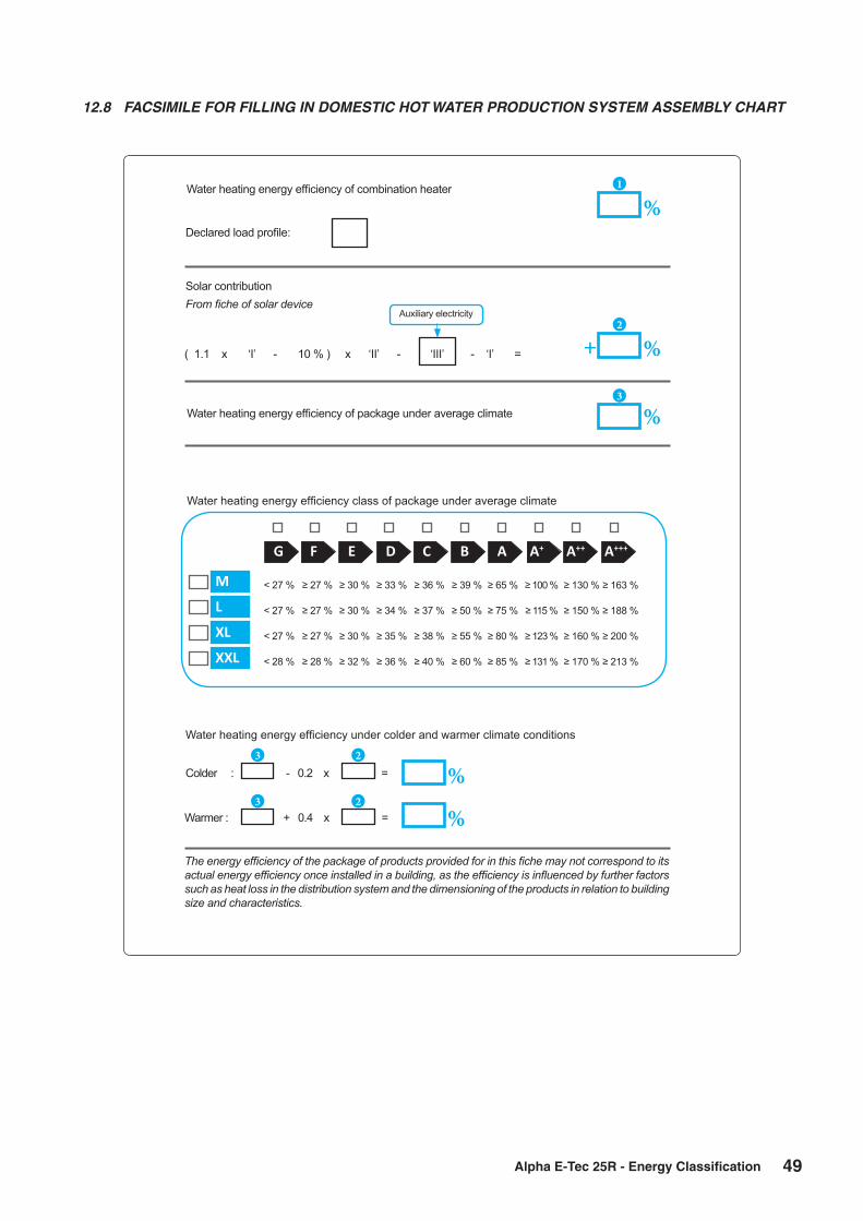
49Alpha E-Tec 25R - Energy Classification
Water heating energy efficiency of combination heater
Water heating energy efficiency of package under average climate
Water heating energy efficiency class of package under average climate
Water heating energy efficiency under colder and warmer climate conditions
Colder : - 0.2 x =
Warmer : + 0.4 x =
Declared load profile:
Solar contributionFrom fiche of solar device
1
%
2
%+( 1.1 x ‘I’ - 10 % ) x ‘II’ - ‘III’ - ‘I’ =
Auxiliary electricity
3
%
G F E D C B A A+++A++A+
< 27 %
< 27 %
< 27 %
< 28 %
≥ 27 %
≥ 27 %
≥ 27 %
≥ 28 %
≥ 30 %
≥ 30 %
≥ 30 %
≥ 32 %
≥ 33 %
≥ 34 %
≥ 35 %
≥ 36 %
≥ 36 %
≥ 37 %
≥ 38 %
≥ 40 %
≥ 39 %
≥ 50 %
≥ 55 %
≥ 60 %
≥ 65 %
≥ 75 %
≥ 80 %
≥ 85 %
≥ 100 %
≥ 115 %
≥ 123 %
≥ 131 %
≥ 130 %
≥ 150 %
≥ 160 %
≥ 170 %
≥ 163 %
≥ 188 %
≥ 200 %
≥ 213 %
M
L
XL
XXL
3 2
3 2
%
%
The energy efficiency of the package of products provided for in this fiche may not correspond to its actual energy efficiency once installed in a building, as the efficiency is influenced by further factors such as heat loss in the distribution system and the dimensioning of the products in relation to building size and characteristics.
12.8 FACSIMILE FOR FILLING IN DOMESTIC HOT WATER PRODUCTION SYSTEM ASSEMBLY CHART

This Commissioning Checklist is to be completed in full by the competent person who commissioned the boiler as a means of demonstrating
compliance with the appropriate Building Regulations and then handed to the customer to keep for future reference.
Failure to install and commission according to the manufacturer’s instructions and complete this Benchmark Commissioning Checklist will invalidate the
warranty. This does not affect the customer’s statutory rights.
GAS BOILER SYSTEM COMMISSIONING CHECKLIST
Customer name: Telephone number:
Address:
Boiler make and model:
Boiler serial number:
Commissioned by (PRINT NAME): Gas Safe register number:
Company name: Telephone number:
Company address:
Commissioning date:
To be completed by the customer on receipt of a Building Regulations Compliance Certifcate*
Building Regulations Notifcation Number (if applicable):
CONTROLS (tick the appropriate boxes)
Time and temperature control to heating
Room thermostat and programmer/timer Programmable room thermostat
Load/weather compensation Optimum start control
Time and temperature control to hot water Cylinder thermostat and programmer/timer Combination Boiler
Heating zone valves Fitted Not required
Hot water zone valves Fitted Not required
Thermostatic radiator valves Fitted Not required
Automatic bypass to system Fitted Not required
Boiler interlock Provided
ALL SYSTEMS
The system has been fushed and cleaned in accordance with BS7593 and boiler manufacturer’s instructions Yes
What system cleaner was used?
What inhibitor was used? Quantity litres
Has a primary water system flter been installed? Yes No
CENTRAL HEATING MODE measure and record:
Gas rate m³/hr OR ft³/hr
Burner operating pressure (if applicable) mbar OR Gas inlet pressure mbar
Central heating fow temperature °C
Central heating return temperature °C
COMBINATION BOILERS ONLY
Is the installation in a hard water area (above 200ppm)? Yes No
If yes, and if required by the manufacturer, has a water scale reducer been ftted? Yes No
What type of scale reducer has been ftted?
DOMESTIC HOT WATER MODE Measure and Record:
Gas rate m³/hr OR ft³/hr
Burner operating pressure (at maximum rate) mbar OR Gas inlet pressure at maximum rate mbar
Cold water inlet temperature °C
Hot water has been checked at all outlets Yes Temperature °C
Water fow rate I/min
CONDENSING BOILERS ONLY
The condensate drain has been installed in accordance with the manufacturer’s instructions and/or BS5546/BS6798 Yes
ALL INSTALLATIONS
Record the following:
At max. rate: CO ppm AND CO/CO²
Ratio
At min. rate: (where possible) CO ppm AND CO/CO²
Ratio
The heating and hot water system complies with the appropriate Building Regulations Yes
The boiler and associated products have been installed and commissioned in accordance with the manufacturer’s instructions Yes
The operation of the boiler and system controls have been demonstrated to and understood by the customer Yes
The manufacturer’s literature, including Benchmark Checklist and Service Record, has been explained and left with the customer Yes
Commissioning Engineer’s Signature
Customer’s Signature
(To confrm satisfactory demonstration and receipt of manufacturer’s literature)
© Heating and Hotwater Industry Council (HHIC) www.centralheating.co.uk
All installations in England and wales must be notified to Local Authority Building Control (LABC) either directly or through a
Competent Persons Scheme. A Building Regulations Compliance Certificate will then be issued to the customer.
*
It is recommended that your heating system is serviced regularly and that the appropriate Service Interval Record is completed.
Service Provider
Before completing the appropriate Service Record below, please ensure you have carried out the service as described in the manufacturer’s instructions.
Always use the manufacturer’s specifed spare part when replacing controls.
SERVICE RECORD
SERVICE 01 Date:
Engineer name:
Company name:
Telephone No:
Gas safe register No:
Record:At max. rate: CO ppm AND CO
²%
At min. rate: (Where Possible) CO ppm AND CO²
%
Comments:
Signature
SERVICE 02 Date:
Engineer name:
Company name:
Telephone No:
Gas safe register No:
Record:At max. rate: CO ppm AND CO
²%
At min. rate: (Where Possible) CO ppm AND CO²
%
Comments:
Signature
SERVICE 03 Date:
Engineer name:
Company name:
Telephone No:
Gas safe register No:
Record:At max. rate: CO ppm AND CO
²%
At min. rate: (Where Possible) CO ppm AND CO²
%
Comments:
Signature
SERVICE 04 Date:
Engineer name:
Company name:
Telephone No:
Gas safe register No:
Record:At max. rate: CO ppm AND CO
²%
At min. rate: (Where Possible) CO ppm AND CO²
%
Comments:
Signature
SERVICE 05 Date:
Engineer name:
Company name:
Telephone No:
Gas safe register No:
Record:At max. rate: CO ppm AND CO
²%
At min. rate: (Where Possible) CO ppm AND CO²
%
Comments:
Signature
SERVICE 06 Date:
Engineer name:
Company name:
Telephone No:
Gas safe register No:
Record:At max. rate: CO ppm AND CO
²%
At min. rate: (Where Possible) CO ppm AND CO²
%
Comments:
Signature
SERVICE 07 Date:
Engineer name:
Company name:
Telephone No:
Gas safe register No:
Record:At max. rate: CO ppm AND CO
²%
At min. rate: (Where Possible) CO ppm AND CO²
%
Comments:
Signature
SERVICE 08 Date:
Engineer name:
Company name:
Telephone No:
Gas safe register No:
Record:At max. rate: CO ppm AND CO
²%
At min. rate: (Where Possible) CO ppm AND CO²
%
Comments:
Signature
SERVICE 09 Date:
Engineer name:
Company name:
Telephone No:
Gas safe register No:
Record:At max. rate: CO ppm AND CO
²%
At min. rate: (Where Possible) CO ppm AND CO²
%
Comments:
Signature
SERVICE 10 Date:
Engineer name:
Company name:
Telephone No:
Gas safe register No:
Record:At max. rate: CO ppm AND CO
²%
At min. rate: (Where Possible) CO ppm AND CO²
%
Comments:
Signature

5 Alpha E-Tec 25R
1. BOILER LOCATIONAlways ensure the following clearances are available around the casing of the boiler:- Top: (horizontal flue) 235 mm, Top: (vertical flue) 150 mm Bottom: 250 mm, Each side: 5 mm, Front: 450 mmDo not store any other articles in a cupboard containing the boiler and never place any clothing or combustible material on or near the boiler or flue pipe.
2. FLUE TERMINALThe terminal on the outside wall must not be allowed to be obstructed. If it is damaged, in any way, turn the boiler off and contact your Service Engineer.Note: The Alpha E-Tec R boiler is a high efficiency condensing boiler and when operating vapour will be emitted from the terminal. This is safe and quite normal.
3. MAINS FAILUREIn the event of an electrical supply failure the boiler will not operate. When the supply is restored, the boiler will return to normal operation. Remember to reset any controls, if fitted, when the supply is restored.If the mains water supply fails, there will be no hot water from the taps. The boiler will continue to provide central heating.
4. ADDITIONAL BATHROOM FITTINGSAny equipment such as mixing valves, showers, bidets etc. must be designed to operate at mains water pressure. Contact your plumbing merchant or installer for advice when considering purchasing such items.
5. CLEANINGUse only a damp cloth and mild detergent to clean the boiler outer casing. Do not use abrasive cleaners.
6. SERVICINGTo maintain efficient and safe operation of your boiler, routine annual servicing is essential.For advice on servicing contact:- The Alpha Helpline: 0344 871 8764.
7. GAS LEAKIf you smell gas or are worried about gas safety, turn off the gas supply. Do not touch any electrical switches, do not smoke, extinguish all naked flames and open all doors and windows. Contact the National Gas Emergency Service immediately on 0800 111 999.8. ELECTRICAL SUPPLYThe boiler requires a 230/240 V ~ 50 Hz supply, fused at 3 A.
To connect a plug:-The colour of the wires in the mains lead of the boiler may not correspond with the coloured markings identifying the terminals in your plug. In this case proceed as follows:-The wire coloured green and yellow must be connected to the terminal in the plug that is marked with the letter E, or by the earth symbol , or coloured green or green and yellow.The blue wire must be connected to the terminal which is marked with either the letter N or coloured black.The brown wire must be connected to the terminal which is marked with the letter L or coloured red.
THE APPLIANCE MUST BE EARTHED.
9. DO NOT TAMPER WITH THE APPLIANCE OR FLUE
At the end of its service life, the appliance must not be disposed of like normal household waste nor abandoned in the environment, but must be removed by a professionally authorised company as required by current legislation. Contact the manufacturer for disposal instructions.
8 IMPORTANT NOTES
9 OPTIONAL BOILER CONTROLS (if fitted)
There is a range of controls available from Alpha to operate your boiler. In addition to the items listed below the Alpha E-Tec R boilers are compatible with most controls available on the market. However to get the most comfort and efficiency from your boiler we recommend the Alpha Climatic controls with enhanced remote boiler functions and efficiency control.Please refer to the instructions provided with the controls for further information on their setting and use.
Available Alpha controls:Alpha Climatic wired programmable boiler energy manager* ...................................................................Part No. 3.022144Alpha Climatic wireless programmable boiler energy manager (boiler mounted receiver)* .......................Part No. 3.022143External weather compensation sensor .....................................................................................................Part No. 3.022383* Should only be used with Alpha Diverter kit and Cylinder Sensor ...........................................................Part No. 6.5500048

4Alpha E-Tec 25R
5 CONDENSATE DRAINAGE
High efficiency (condensing) boilers remove more useful heat from the combustion gases, resulting in additional water vapour which is collected within the boiler (as condensate) and run to a suitable drainage point via the condensate drainage pipe.
Where possible the condensate drain should be connected internally to a waste pipe within the property to prevent the risk of freezing.
If the condensate drain pipe runs outside it should be fitted with increased diameter pipe and be suitably lagged to reduce the risk from freezing.
In situations where there are likely to be extremes of temperature or wind-chill the use of a proprietary trace-heating system for external condensate drainage pipework, incorporating an external frost thermostat, should be considered.
6 GAS SAFETY REGULATIONS
Current Gas Safety (Installation and Use) Regulations:-
It is the law that all gas appliances are installed and serviced by a competent person, i.e. Gas Safe registered personnel. Failure to install or service appliances correctly could lead to prosecution. It is in your interest and that of safety to ensure compliance with the law. The manufacturer's instructions must not be taken in any way as over-riding statutory obligations.
The Benchmark Checklist must be fully completed by the installer on installation of the boiler. The Benchmark Checklist is shown in back of the Installation and Servicing instructions. All Gas Safe registered installers carry a Gas Safe ID card and have a registration number. Both should be recorded in the Checklist. You can check your installer is Gas Safe registered by calling Gas Safe on 0800 408 5500.
It is a requirement that the boiler is installed and commissioned to the manufacturers instructions and the data fields on the commissioning checklist completed in full.
To instigate the boiler guarantee the boiler needs to be registered with the manufacturer within one month of the installation.
To maintain the boiler guarantee it is essential that the boiler is serviced annually by a Gas Safe registered engineer who has been trained on the boiler installed. The service details should be recorded on the Benchmark Service Interval Record and left with the householder.
7 BENCHMARK COMMISSIONING and SERVICING

3 Alpha InTec² 25XE and 28XE
Summer setting - This function can only be used for hot water operation if the boiler is fitted with an Alpha Diverter kit or Relay kit. With the Alpha Diverter kit fitted the DHW control knob on the boiler will independently control the temperature of the hot water cylinder. With the DHW relay kit fitted the DHW control knob on the boiler sets the water temperature leaving the boiler to heat the hot water cylinder.Note: This must be set higher than the cylinder thermostat to achieve the cylinder set temperature.
Winter setting - In this mode the boiler will operate in both heating and hot water mode according to the control requests. With the Alpha Diverter kit fitted the heating of the cylinder takes priority over heating and once the cylinder set temperature is reached the boiler will revert to heating if rquired according to the temperature set on the boiler heating control knob.Note: This is the radiator water temperature and not room temperature.
With the DHW relay option the boiler will operate according to the external control request for either heating or hot water or both. When a request for heating the hot water cylinder is given, the water temperature for both heating and hot water will be the at the set point of the hot water control knob of the boiler reverting to the heating control knob temperature once the cylinder reaches the thermostat set point and heating is requested.
For a system fitted with a standard S or Y plan layout with external controls the boiler should always be left in winter mode. During operation the boiler LCD will display the temperature of the water leaving the boiler.
Note: When using a standard Y or S plan system the central heating water temperature must be set above the cylinder thermostat value using the central heating control knob 6 in Fig. 1.
External weather compensation sensor (only for use with the Alpha Diverter Kit or Relay unit) - The temperature of the central heating water can be adjusted by using the central heating buttons (items 6 and 7 in Fig. 1). When the heating is on the temperature of the water leaving the boiler to the radiators will be displayed.
If an external weather compensation sensor is fitted, indicated by the symbol (item 18 in Fig. 1) in the display, it will automatically vary the temperature of the water in the radiators and on mild day the radiators will not feel as hot as on a cold day, this is normal and not a fault with the boiler or heating circuit. The room temperature will still be maintained as set by the room thermostat.
When an external weather sensor is fitted, the central heating control knob (item 5 in Fig. 1) will no longer adjust the flow temperature in °C, instead the display will show a scale of 1 to 9. Each number corresponds to a line on the graph in Fig 2 i.e. line 6 will give a flow temperature of 60°C when the external temperature is 10°C.
Note: This is the temperature of the water supplied to the radiators and not the desired room temperature. The time and temperature will still be maintained according to the setting of the room thermostat.
3 HEATING AND HOT WATER TEMPERATURE
Fig. 2 - External weather compensation sensor fitted
Flo
w te
mp
eratu
re (°
C)
External temperature (°C)
27155-5 100-10-15 20
25 (25)
60 (40)
80 (50)
Flow temperature in bracketsie. 25 to 50°C range when boileris used with a low temperaturesystem such as under floor heating
Setting 1 to 9 as selected usingthe central heating selector switch
98765
4
3
2
1
0
The boiler has a built in frost protection function to protect the boiler (only) from freezing. If water within the boiler falls below 4°C the boiler will fire in heating mode and raise the temperature of the heating water (in the boiler only) to 42°C. If the circulation pump is connected to terminal L2 and N2 the pump will be active during frost protection mode.
For this function to be active the gas and electricity supplies to the boiler must be turned on and the boiler be in either 'Standby' or 'On' mode and the frost protection enabled in the boiler parameters.
Further protection for the mains water supply and heating circuit must be provided separately.
If Alpha external controls are fitted, a frost protection setting is incorporated into the room thermostat activating the central heating when the temperature falls below 5°C.
4 FROST PROTECTION
Alpha E-Tec 25R

2Alpha E-Tec 25R
Please read these instructions carefully before operating your boiler.
The Alpha E-Tec R range of high efficiency condensing boilers incorporate the latest technology in boiler design. With improved burner efficiency and reduced electrical consumption together with high quality and reliability.
The boiler output will automatically adjust according to the requirements of the system.
The E-Tec R range are designed to work with most central heating controls however we recommend the enhanced Alpha Climatic boiler energy manager further improving the system efficiency by varying the system temperature depending on the room temperature and heat losses - to be used only with the Alpha Diverter kit if a DHW cylinder is used.
In addition all E-Tec R models feature optional connections for an outside sensor to enable the boilers built in weather compensation feature.
The boilers will provide central heating when required during the on times as set according to the controls fitted.
Refer to Section 2 of the Installation and Servicing document for the meaning of the information symbols.
Fig. 1
2 OPERATING THE BOILER
1 INTRODUCTION
Switch the boiler on at the mains supply socket switch. The boiler will be in either 'Standby' or 'On' mode.
By pressing button 1 (see Fig. 1) the Standby or On mode can be selected, or press and hold the button 1 for eight seconds to turn the boiler off.
Standby - In this mode the boiler will not provide hot water or central heating, but frost protection and pump circulation (if the pump has been connected to the boiler terminals) features are still active and frost protection enabled.
Off - In this mode there is electrical power to the boiler but the boiler will not function in any condition.
On - In this mode the boiler can be switched between 'Summer' or 'Winter' settings by pressing the button 2 (see Fig. 1).
The boiler can be used by children at least 8 years old as well as by persons with reduced physical, sensory or mental capabilities, lack of experience or required knowledge providing that they are under surveillance, or after they have been instructed relating to the safe use and have understood the potential dangers. Children must not play with the appliance. Cleaning and maintenance destined to be performed by the user cannot be carried out by unsupervised children.The boiler controls are located on the control panel.Make sure the heating system is filled.
1 2 3 4 56 21
RESET
BOOST
bar
°C
x100rpm
8910111213
14
15 16 17 18 19 20
RESET
INFO
RESET
BOOST
bar
°C
x100rpm
1 On-Off/Standby button2 Summer/Winter button3 Reset button4 Information button5 Domestic hot water temperature
control knob with Alpha diverter kit or DHW relay fitted
6 Central heating water temperature control knob
7 N/A8 DHW mode active9 Boiler locked, reset via 'RESET' button10 Flame present symbol and relative
power scale11 Operating in summer mode12 Operating in winter mode13 Central heating mode active14 Temperature indicator, boiler info and
error codes15 Boiler in Stand-by mode16 Climatic control fitted17 Solar function (not used on this model)18 Functioning with external temperature probe
active (optional)19 Boiler connected to remote control (optional)20 FlowSmart option (not used on this model)21 Optional boiler controls (if fitted)
UserInstructions
E-Tec 25R
Wall Mounted, Fan Assisted, Room Sealed,Gas Fired, High Efficiency Condensing Regular Boiler
Nepicar House, London Road,Wrotham Heath, Sevenoaks,
Kent TN15 7RS
For Technical help or for Service call ...ALPHA HELPLINE Tel 0344 871 8764
website: www.alpha-innovation.co.uk
Set for use with Natural Gas
Leave these instructions with the User
These instructions have been carefully prepared but we reserve the right to alter the specification at any time in the interest of product improvement.© Alpha Therm Limited 2018.
Related Documents