E-PLEX ® 2000 and 2400 Series PowerPlex 2000 and 2400 Series INSTALLATION INSTRUCTIONS

Welcome message from author
This document is posted to help you gain knowledge. Please leave a comment to let me know what you think about it! Share it to your friends and learn new things together.
Transcript

E-PLEX® 2000 and 2400 SeriesPowerPlex 2000 and 2400 SeriesINSTALLATION INSTRUCTIONS
2
APPLICABLE FOR UNITED KINGDOM INSTALLATIONS ONLY
It is the responsibility of the installer to ensure that the installation of this product complies with the relevant regulations applicable to the territory / country (UK only).
Intumescent gasket requirements for fire doors
Product Fire Door type - timber or mineral composite (to BS EN 1634-1)
Around tubular latch or lockcase
Behind forend Behind strike plate (and any back box)
Kaba Pack
E-plex 5000 E-plex 5200 E-plex 5700 ⁄
E-plex 2000 PowerPlex 2000
⁄
Simplex (L)1000 Simplex 5000 Simplex 6200 Simplex 8100
⁄
Simplex 7100 with tubular latch or tubular bolt
⁄
3
TABLE OF CONTENTS
A. Cylindrical Installation . . . . . . . . . . . . . . . . . . . . . . . . . . . . . . . . . . . . . . . . . . . . .4
B. Mortise Installation . . . . . . . . . . . . . . . . . . . . . . . . . . . . . . . . . . . . . . . . . . . . . . . .11
C. Exit Trim Installation . . . . . . . . . . . . . . . . . . . . . . . . . . . . . . . . . . . . . . . . . . . . . .33
D. Installing Outside Lever on Non-Mechanical Override . . . . . . . . . . . . . . . . .37
E. Reversing the Outside Lever for Series Without Mechanical Override . . .37
F. Installing Optional K-I-L Key or Best Removable Core . . . . . . . . . . . . . . . .38
Override and Outside Lever
G. Testing the Operations of the Outside Lever . . . . . . . . . . . . . . . . . . . . . . . .40
H. Testing the Mechanical Key Override with Change Key . . . . . . . . . . . . . . . .41
I. Changing Lock Cylinders . . . . . . . . . . . . . . . . . . . . . . . . . . . . . . . . . . . . . . . . . .42
J. Changing Best-Type Core . . . . . . . . . . . . . . . . . . . . . . . . . . . . . . . . . . . . . . . . .43
K. Removing and Reassembling the Outside Lever . . . . . . . . . . . . . . . . . . . . . .43
L. Installing Rubber Bumpers . . . . . . . . . . . . . . . . . . . . . . . . . . . . . . . . . . . . . . . .44
M. Installing Battery Pack . . . . . . . . . . . . . . . . . . . . . . . . . . . . . . . . . . . . . . . . . . . .44
N. Testing the Operation of the Lock . . . . . . . . . . . . . . . . . . . . . . . . . . . . . . . . . .45
Warranty card . . . . . . . . . . . . . . . . . . . . . . . . . . . . . . . . . . . . . . . .center of book
For technical assistance, call 1-800-849-TECH (8324) or 336-725-1331
Please read and follow all directions carefully.
These instructions are designed for use by maintenance professionals or lockinstallers who are familiar with common safety practices and competent toperform the steps described. Kaba Access Control is not responsible for dam-age or malfunction due to incorrect installation.
Important: Carefully inspect windows, doorframe, door, etc. to ensure that therecommended procedures will not cause damage. Kaba Access Control standardwarranty does not cover damages caused by installation.
4
A. CYLINDRICAL
CHECKLISTParts and Tools List
Each E-Plex/PowerPlex 2xxx lockset includes:
• Outside lock housing
• Inside lock assembly
• Outside lever
• Gasket for outside lock housing (not for PowerPlex 2000 versions)
• Cylindrical latch
• Cylinder drive unit
• Battery holder with 3 AA batteries (not included in PowerPlex 2000 versions)
• Drilling templates
• Hardware bag, includes:
- Square spindle
- Phillips screw (6-32 x 5⁄16") (not for PowerPlex 2000 versions)
- Strike kit
- (3) mounting screws (12-24, 1⁄8" hex head)
- Allen Key 1⁄8" — Allen Key 5⁄64"
- (2) 1" (25 mm) Phillips mounting screws
- (1) extension spring
- (4) pairs of Flat Head screws 10-24
- (3) spacers
• Key Override (Optional)
- (1) cylinder with 2 keys for override (if equipped)
- (1) cylinder plug (if equipped)
- (1) cylinder cap (if equipped)
- (2) adaptors for best-type cylinders (if equipped)
- (1) override shaft tool (if equipped)
Warning: For E-Plex/PowerPlex 2000 locks, the Master Code of this lock hasbeen factory preset: 1,2,3,4,5,6,7,8. To activate lock functions, the mastercombination must be changed at the time of installation.For E-Plex 24xx locks, you will have to generate an access code using the webapplication to test the lock operation.

5
DIAGRAM OF LOCK:
BackFront(A)
(D)
(B)
(E)
(F)(G)
(H)
(I)
(J)
(C)
TOOLS REQUIRED:
TOOLS REQUIRED:• Safety glasses• 1⁄2" (13 mm) chisel• 1⁄8" (3 mm) drill bit• 1⁄2" (13 mm) drill bit• 7⁄8" (22 mm) drill bit or hole saw• 1" (25 mm) drill bit or hole saw• 21⁄8" (54 mm) hole saw• Drill• Awl or center punch• Rubber mallet• Small flat screwdriver (less than 1⁄8")
• Phillips screwdriver (#2)• Fine steel file• Router• Adjustable square• Tape measure• Pencil• Tape• Cleaning supplies (drop cloth, vacuum)
• Spanner screwdriver #6
(A) Lock housing(B) Inside drive hub(C) Nylon washer(D) Drive tube
(E) Lever catch(F) Countersink (G) Outside Lever(H) Cap (if equipped)
(I) Cylinder (if equipped)(J) Cylinder plug (if equipped)

6
A-1. Door Preparation
Note: Drill from both sides of the door to prevent unsightly damage.
1. Determine which template fits your E-Plex 2xxx installation (either the 2 3⁄8" [60 mm] Backset or the 2 3⁄4" [70 mm] Backset).
2. Place appropriate paper template (supplied) onto door and mark forholes. Drill the three 1⁄2" (13 mm) holes first. Next drill the 2 1⁄8" (54 mm)cross bore hole. Drill the 1" (25 mm) hole last.
3. Mortise door edge for latch unit faceplate 3⁄16" (5 mm) deep to dimensions shown. Insert latch unit into the 1" (25 mm) hole, making certain that the latch bolt bevel faces direction of closing door.
4. Secure the latch to the door using two 1" (25 mm) Phillips Mounting screws supplied. Latch unit faceplate must be flush with door (for doors with 1" diameter hole, use sleeve on latch).
A-2. LOCK HANDING
The E-Plex 2xxx is a non-handed lockthat is preassembled for left-handdoor installations.
1. Determine the hand of your door. For Left Hand doors, proceed to section C.For Right Hand doors, follow steps below.
2. Remove the two connecting screws from thecylindrical drive unit. Rotate cylindrical driveunit 180º. Reposition spacer(s) as foundbefore disassembly. Remount drive unit withthe two connecting screws.
D
Closing Direction
Left Hand Left Hand Reverse Bevel R
LEFT HAND DOOR
Right Hand Right Hand Reverse Bevel
RIGHT HAND DOORL
LH Assembly RH Assembly
Cylindrical Drive Unit Position

7
A-3. DOOR THICKNESS
Depending on the kind of spacers shipped with the lock, choose Table 1 orTable 2 to prepare the attachment plate and cylindrical drive unit for doorthickness different than 1 3⁄4" assembled in the factory.Note: It is very important to assemble the spacers in the position shown.
1. LOCK WITH 3 DIFFERENT SPACERS
The cylindrical unit and plate assembly isshipped assembled in factory for 1 3⁄4"(44 mm) door thickness (1 11⁄16" [43 mm]to less than 1 7⁄8" [48 mm]) with 2 spac-ers "04"; 1 spacer "02" and 2 flat headscrews 5⁄8" (16 mm) LG. For other doorthicknesses, use Door Thickness Table 1for appropriate spacers and screwsincluded in the hardware bag.
Prepare attachment plate and cylindrical drive unit for door thicknesses less than 1 11⁄16"(43 mm) or 1 7⁄8" (48 mm) andabove according to theDoor Thickness Table 1.
Door Thickness Table 1Door Spacer Spacer Spacer Screw
Thickness 02 04 05 length
1 3⁄8" (35 mm) to - 1 - 3⁄8" 1 9⁄16" (40 mm) (10 mm)Over 1 9⁄16" (40 mm) to - 2 - 1⁄2" less than 1 11⁄16" (43 mm) (13 mm)
1 3⁄4" (44 mm) DOOR 1 2 - 5⁄8" 1 11⁄16 (43 mm) to less than 1 7⁄8" (16 mm)
1 7⁄8" (48 mm) to 1 - 1 5⁄8" 1 15⁄16" (49 mm) (16 mm)
Over 1 15⁄16" (49 mm) to 2 - 1 3⁄4"less than 2 1⁄8" (54 mm) (19 mm)
2 1⁄8" (54 mm) to - 1 1 3⁄4" 2 3⁄16" (56 mm) (19 mm)
Over 2 3⁄16" (56 mm) to 2 1 1 7⁄8" 2 3⁄8" (60 mm) (22 mm)
Over 2 3⁄8" (60 mm) to - - 2 7⁄8" 2 1⁄2" (64 mm) (22 mm)
Screws
CylindricalUnitAssembly
0504
02
Spacers
AttachmentPlate
Correct Position of SpacersSee Table 1

8
2. LOCK WITH 2 DIFFERENT SPACERS
The cylindrical unit and plate assembly isshipped assembled in factory for 1 3⁄4"(44 mm) door thickness up to 1 13⁄16" [46mm] with 2 spacers "07"; 1 spacer "08"and 2 flat head screws 5⁄8" (16 mm) long.For other door thicknesses, use DoorThickness Table 2 for appropriate spac-ers and screws included in the hardwarebag.
Door Thickness Table 2
Door Spacer Spacer ScrewThickness 07 08 length
1 3⁄8" (35 mm) to 1 9⁄16" (40 mm) 2 - 3⁄8" (10 mm)
1 5⁄8" (41 mm) to 1 11⁄16" (43 mm) 1 1 1⁄2" (13 mm)
1 3⁄4" (44 mm) to 1 13⁄16" (46 mm) 2 1 5⁄8" (16 mm)
1 7⁄8" (48 mm) to 1 15⁄16" (49 mm) - 2 5⁄8" (16 mm)
2" (51 mm) to 2 1⁄16" (52.5 mm) 1 2 3⁄4" (19 mm)
2 1⁄8" (54 mm) to 2 3⁄16" (56 mm) 2 2 3⁄4" (19 mm)
2 1⁄4" (57 mm) to 2 5⁄16" (59 mm) - 3 7⁄8" (22 mm)
2 3⁄8" (60 mm) to 2 1⁄2" (64 mm) 1 3 7⁄8" (22 mm)
Screw Length Full Scale
Length 3⁄8" (10 mm)
Length 1⁄2" (13 mm)
Length 5⁄8" (16 mm)
Length 3⁄4" (19 mm)
Length 7⁄8" (22 mm)
Correct Position of SpacersSee Table 2

9
A-4. INSTALLING LOCK HOUSINGS1. Remove the cylindrical plate assembly from
the outside housing (a). Insert the slotted endof the square spindle into the outside housing lever hub until it locks, at an angle of 45º.(The spindle can be removed by pulling on it,if oriented incorrectly.)
2. Assemble gasket onto the outside housing (a). Assemble cylindrical plate assembly onto the outside lock hous-ing. (Not required for PowerPlex 2000 versions)
3. Place the outside housing (a) andcylindrical plate assembly on thedoor so that it engages the latch asshown.
4. On the inside trim assembly, turn the lever to the correct horizontal rest position for the handing of the door.Install the tension spring (l) between the stop plate (h) and the post (p).
Square Spindle Position
correct incorrect
a
Cylindrical PlateAssembly
(outside)
cylindricalunit
latch
h
p
l
Gasket (not forPowerPlex 2000version)

10
A-5. INSTALLING THE STRIKENote: Use only the strike and strike box supplied. Theuse of non-approved parts will result in a functionalityproblem and may void the warranty.
1. Mark location of strike on the door frame, makingcertain that the strike opening is aligned withlatch bolt.
2. Mortise doorframe for strike 3⁄32" (3 mm)deep minimum to dimensions shown. Makecut out for dust box. Secure strike to thedoor frame using two 1" (25 mm)combination screws.
Caution: Check the operation of the latch by making sure that the deadlatchstops against the strike as shown and does not slide into the strike openingwhen the door is closed. If that situation occurs, then a total lockout mayoccur. This will void our warranty of the complete lock mechanism. Ifnecessary, correct the door over-travel by using the rubber bumpers asdescribed in Section P (Installing Rubber Bumpers).
5. Put the thumbturn (T) in a verticalposition. Assemble 3 spacers (S) onthe door (for recent models only).Place the inside trim assembly on thedoor so that the upper and lower spindles (F) and (G) engage thethumbturn and the inside lever.Fasten to the outside housing usingthe three 1/8" hex drive mountingscrews (I). Install the screws withouttightening. Verify the inside lever andthumbturn operates smootly. If notmove the inside and outside housingsslightly. Then tighten the screws.
11
B. MORTISE
Checklist and Exploded Views (Mortise Only)
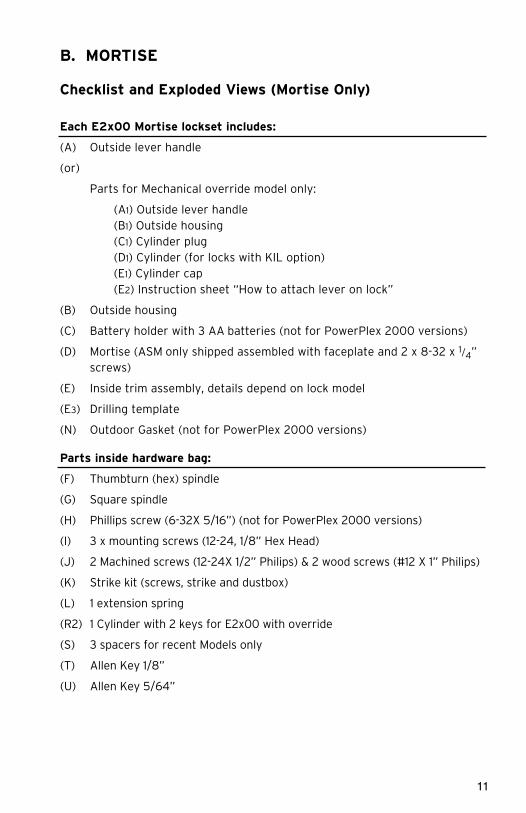
Each E2x00 Mortise lockset includes:
(A) Outside lever handle
(or)
Parts for Mechanical override model only:
(A1) Outside lever handle(B1) Outside housing(C1) Cylinder plug(D1) Cylinder (for locks with KIL option)(E1) Cylinder cap(E2) Instruction sheet “How to attach lever on lock”
(B) Outside housing
(C) Battery holder with 3 AA batteries (not for PowerPlex 2000 versions)
(D) Mortise (ASM only shipped assembled with faceplate and 2 x 8-32 x 1/4” screws)
(E) Inside trim assembly, details depend on lock model
(E3) Drilling template
(N) Outdoor Gasket (not for PowerPlex 2000 versions)
Parts inside hardware bag:
(F) Thumbturn (hex) spindle
(G) Square spindle
(H) Phillips screw (6-32X 5/16”) (not for PowerPlex 2000 versions)
(I) 3 x mounting screws (12-24, 1/8” Hex Head)
(J) 2 Machined screws (12-24X 1/2” Philips) & 2 wood screws (#12 X 1” Philips)
(K) Strike kit (screws, strike and dustbox)
(L) 1 extension spring
(R2) 1 Cylinder with 2 keys for E2x00 with override
(S) 3 spacers for recent Models only
(T) Allen Key 1/8”
(U) Allen Key 5/64”

12
Tools Required:
• Safety Glasses
• 1/2” (13mm) chisel
• 1/8” (3mm) drill bit
• 1/2” (13mm) drill bit
• 1” (25mm) drill bit or hole saw
• Drill
• Awl or center punch
• Hammer Rubber mallet
• Small flat screwdriver
• Philips screwdriver (#2)
• Fine steel file
• Mortising machine
• Router
• Mortise faceplate router template
• Adjustable square
• Tape measure
• Pencil
• Tape
• Cleaning supplies (drop cloth, vacuum)

13
American Standard Mortise illustrated
A
C
H
BN
F
D
S
G
J
J
L
I
E
K
B1
D1
C1
A1
E1

14
B-1. Installation of Standard ASM Models
1. Check the Mortise Handing
a. Compare the mortise with the diagram below. If the mortise is the correct handing for the door, continue with step 2.
Note: Refer to B-2 to change the handing of a field-reversible mortise.

15
2. Install the Strike
a. Align the paper template on the door frame at the desired handle height, and along the vertical center line of the mortise (CL), which is also the center line of the door edge, allowing for any bumpers on the door frame.
Note: Respect applicable building codes regarding handle height.
b. Mark the locations of the dust box cutout and mounting screws for the strike.
c. Mortise the door frame to receive the dust box, and drill the pilot holes for the mounting screws (dimensions and depths marked on template).
d. Position the strike against the doorframe and align it with the mounting screw holes. Trace the outline of the strike.
(CL)

16
e. Remove material from within the strike outline so that the strike will be flush with the doorframes.
f. For ASM, install the dust box (optional for wood door frames, required for metal door frames), and check the strike handing on the template. Install the strike using the screws provided. Use wood screws for wood frame and machined screws for steel frames.
Note: When strike is installed on wood frames under one inch thick, wood screws supplied are not adequate. Use screws of efficient length to engage the structural stud behind the frame. Use only the strike and dust box supplied. Use of non-approved parts may void the warranty.
17
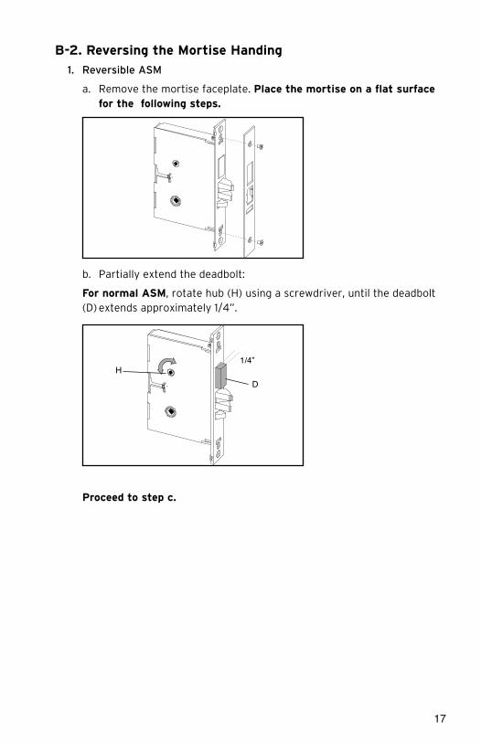
B-2. Reversing the Mortise Handing
1. Reversible ASM
a. Remove the mortise faceplate. Place the mortise on a flat surface for the following steps.
b. Partially extend the deadbolt:
For normal ASM, rotate hub (H) using a screwdriver, until the deadbolt(D) extends approximately 1/4”.
Proceed to step c.
1/4”H
D

18
For Autodeadbolt ASM, rotate hub (H) until the deadbolt (D) is fully retracted. The deadbolt will extend approx. 1/16” from the mortise case.
Hold deadbolt (D) gently. Press and release the auxiliary latch (X). You should feel the deadbolt trigger and begin to extend under the force of the spring.
Release the deadbolt (D) gently. It should extend to 5/16” approx. and stop. If the deadbolt extends past this point, gently press it in until it locks at 5/16” throw, or start step b again.
D (hold gently)
X (press and release)
D
5/16”
D
1/16”
H

19
1. Reversible ASM (continued)
c. Push in the latch bolt (L) to the middle of its stroke, and hold it there. (Continue Step 1 and 2)
Hold the latch (L) inside the mortise, and insert the tailpiece retaining tool (S, part #027-510382 or #041-513342 available separately) so that the tailpiece (T) will not drop inside the mortise case. Hold the tool and the latch with one hand, and slide up the tailpiece using a small screwdriver.
Continue to hold tool (S). Release the latch bolt (L) and keep the anti-friction latch (F) toward the flat side of the latch bolt so that the bolt extends fully.
1 2
Use a small screwdriver to lift unlock mechanism.
Unlock PositionLock Position
Push in the latchbolt to the end of the stroke, and hold it there.
L L
L
T
S (part #027-510382)
L
FS

20
d. Pull out the latch bolt (L), until it just clears the front plate. (Note: If you remove the bolt completely, you must turn it 90° to re-insert it.)
Rotate the latch bolt (L) 180°. Re-insert it to the end of its stroke.
Holding tool (S) in place, re-engage tailpiece (T) with latch bolt (L) (slide tailpiece down). There may be some play required to align the parts. Remove the tool (S).
Release the latch to the middle of the stroke and hold it there. Use a small screwdriver to push the lock mechanism back on lock position (see step 1 and 2) .
Note: The lock mechanism has to be horizontal on lock position
L
180°
L
L
T
S

21
f. The mortise should look like the diagram below. (Check the orientation of the latch bolt and auxiliary latch.) Check the bevel of the mortise and change it if required as described in section B-4, paragraph 6.
m
For LH (left hand) and RHR (right hand reverse)
For RH (right hand) and LHR (left hand reverse)
ASM
WV
WV
Only apply to mortise no deadbolt, auto-deadbolt and armed automatic deadbolt
e. Release the latch bolt (L). Position the latch bolt so that the bottom tooth of the anti-friction latch (F) remains inside the mortise case as shown.
Note: If the tooth of (F) is outside the mortise, you will not be able to re-assemble the faceplate on the mortise.
L
FL
F (tooth)
mortise
bottom view
6
m
a

22
B-3. Additional steps for Autodeadbolt ASM inside trim assembly
If not already installed at the factory, put the thumbturn in the vertical position andinstall all four (4) parts (M) as shown, on the inside trim assembly.
Turn the thumbturn all the way to the right for a RH installation (arrow on M2 points UP),or all the way to the left for a LH installation (arrow on M2 points DOWN). The thumbturnshould stop in the vertical position, and the stopper cam (M2) will be in the position illus-trated below.

23
Place 3 spacers (S) on the door (for recent models only). Place the inside trimassembly on the door so that the upper and lower spindles (F) and (G) engage thethumbturn and the inside lever. Fasten to the outside housing using the three 1/8"hex head mounting screws (I).
Note: For Auto Deadboltmodels the gap between the mortise front plate and thestrike must not exceed 1/4 “
Turn Knob VerticalX
Door Frame
M
Door Door Frame
Mortise
Max. 1/4"

24
KABA E-PLEX® and PowerPlex 2xxx SERIESLIMITED WARRANTYKaba Access Control warrants this product to be free from defects in materialand workmanship under normal use and service for a period of three (3) years.Kaba Access Control will repair or replace, at our discretion, 2xxx Series Locksfound by Kaba Access Control analysis to be defective during this period. Ouronly liability, whether in tort or in contract, under this warranty is to repair orreplace products that are returned to Kaba Access Control within the three (3)year warranty period.
This warranty is in lieu of and not in addition to any other warranty or condi-tion, express or implied, including without limitation merchantability, fitness forpurpose or absence of latent defects.
ATTENTION: This warranty does not cover problems arising out of improperinstallation, neglect or misuse. All warranties implied or written will be null andvoid if the lock is not installed properly and / or if any supplied component partis substituted with a foreign part. If the lock is used with a wall bumper, thewarranty is null and void. If a doorstop is required, we recommend the use of afloor secured stop.
The environment and conditions of use determine the life of finishes on Kaba Access Control products. Finishes on Kaba Access Control productsare subject to change due to wear and environmental corrosion. Kaba AccessControl cannot be held responsible for the deterioration of finishes.
Authorization to Return GoodsReturned merchandise will not be accepted without prior approval. Approvalsand Returned Goods Authorization Numbers (RGA Numbers) for the 2xxxSeries are available through our Customer Service department in Winston-Salem, NC (800) 849-8324. The serial number of a lock is required to obtainthis RGA Number. The issuance of an RGA does not imply that a credit orreplacement will be issued.
The RGA number must be included on the address label when material is returned to the factory. All component parts including latches and strikes(even if not inoperative) must be included in the package with return. All merchandise must be returned prepaid and properly packaged to the addressindicated.

KABA
AC
CES
S &
DAT
A SY
STEM
S AM
ERIC
AS29
41 IN
DIA
NA
AVE
WIN
STO
N-S
ALEM
, NC
271
99-3
770
NO
PO
STAG
EN
ECES
SAR
YIF
MAI
LED
IN T
HE
UN
ITED
STA
TES
BU
SIN
ESS
REP
LY M
AIL
FIR
ST-
CLA
SS
MA
ILW
INS
TON
SA
LEM
NC
PE
RM
IT N
O. 1
563
PO
STA
GE
WIL
L B
E P
AID
BY
AD
DR
ES
SE
E

Thank you for purchasing our product. In order toprotect your investm
ent and to enable us to betterserve you in the future, please fill out this registrationcard and return it to K
aba Access C
ontrol, or register online at w
ww.ka
baaccess.co
m.
This lock w
ill be used in
what ty
pe of facility?
oCom
mercial B
uildingo
Industrial / Manufacturing
oAirport
oCollege
/University
oGovernm
ent/Military
oSchool/Educational
oHospital/H
ealthcareo
Other (please specify)
What area is bein
g secured w
ith this lock?
(e.g. Front Door, C
ommon D
oor, Exercise Room
)
This lock is:
oNew
Installation
oReplacing a conventional keyed lock
oReplacing a K
aba Mechanical Pushbutton Lock
oReplacing a K
aba Electronic Access C
ontrol
oReplacing a K
eyless Lock other than Kaba
How did you
learn abou
t Kaba A
ccess Control P
ushbutton
Locks?
oAdvertisem
ento
Previous Use
oInternet / W
ebo
Another U
se
oLocksm
itho
Maintenance
oTraining C
lasso
Other (please specify)
What w
as your reason
for buying th
is lock?
Who in
stalled your lock?
oLocksm
itho
Maintenance
oOther
oCheck h
ere if you would like m
ore information
on Kaba A
ccess Control locks.
Nam
e
Position
Com
pany
Address
City
StateZIP (P
ostal Code)
Country
Phone
Nam
e of Dealer Purchased From
Date of Purchase
Lock Model N
umber
REGISTRATION CARD

25
B-4. Install the Mortise
1. Mark the handle height on the edge of the door, as determined directly from the strike.
For ASM, the axis of rotation of the handle is level with the bottom lip of the strike.
2. Align the template along the vertical center line of the mortise (CL) at the desired handleheight, and tape it to the door. Mark all holesand cutouts for the mortise in the edge of thedoor and remove the template.
ESM Strike
(ESM)
ASM Strike
11/4"
Door(CL)
(ASM shown) LH/RHR
3. Locate the two sets of vertical fold lines on the template allowing you to adjust the positioning of the template depending on the bevel of the door.
If the door has no bevel, fold the template along the solid lines. Align the fold with the edge of the door and mark the holes for the lock. Repeat on the other side of the door.
If the door has a 3º bevel, fold and align the dashed line marked “H" on thetemplate with the higher-beveled edge of the door and mark the lock holeson that side of the door. Repeat on the side with the lower-beveled edgeusing the dashed line marked “L". Remove the template.
2
5
4
3
(ASM shown) LH/RHR
26
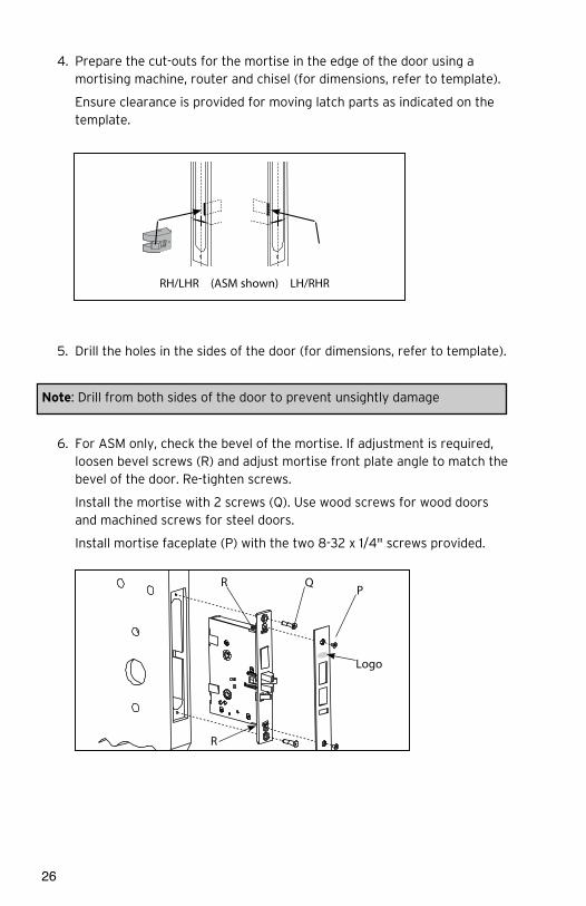
4. Prepare the cut-outs for the mortise in the edge of the door using a mortising machine, router and chisel (for dimensions, refer to template).
Ensure clearance is provided for moving latch parts as indicated on the template.
5. Drill the holes in the sides of the door (for dimensions, refer to template).
Note: Drill from both sides of the door to prevent unsightly damage
6. For ASM only, check the bevel of the mortise. If adjustment is required, loosen bevel screws (R) and adjust mortise front plate angle to match the bevel of the door. Re-tighten screws.
Install the mortise with 2 screws (Q). Use wood screws for wood doors and machined screws for steel doors.
Install mortise faceplate (P) with the two 8-32 x 1/4" screws provided.
RH/LHR (ASM shown) LH/RHR
(ASM shown) LH/RHR
Logo
PQR
R

27
B-5. Install the Outside Housing and Inside Trim Assembly for 2000 and 2400 Series without Key Override (for E2000 and 2400 Series Key Override, see Section F)
1. Install the gasket (N) (if required) on the outside housing prior to assembly, aligning the notch in the gasket with the battery compartment.
2. Insert the slotted end of the square spindle (G) into the outside lever hub until it locks, at an angle of 45º. (The spindle can be removed by pulling on it, if oriented incorrectly.)
3. Insert the thumbturn spindle (F) in the upper hub of the outside housing. (It will clip in place.)
Note: For doors more than 2 1/2” thick, order the appropriate hardware bag to receive the correct length of spindles and mounting screws.
4. Place the outside housing on the door so that the spindles engage the hubs on the mortise.
I
incorrect
I
Outdoor Gasket
Notch
incorrect
I
Square Spindle Position
correct incorrect

28
5. On the inside trim assembly turn the lever to the correct horizontal restposition for the handing of the door. Install the tension spring (L)between the handle (H) and the post (P).
Note: For Autodeadbolt ASM, Office and Storeroom models, refer to section B-3
6. Put the thumbturn (T) in a vertical position. Place 3 spacers (S) on thedoor (for recent models only) and place the inside trim assembly on thedoor so that the upper and lower spindles (F) and (G) engage the thumb-turn and the inside lever. Fasten to the outside housing using the three1/8" hex drive mounting screws (I). Install the screws without tightening.Verify the inside lever and thumbturn operates smootly. If not move theinside and outside housings slightly. Then tighten the screws.
7. Assemble the lever on the outside housing, in the horizontal rest positionappropriate to the handing of the door. Simply push the lever onto thetube until it clicks in place. If more force is required, use a rubber mallet.Test the attachment of the handle by pulling smartly on it. (For locks withkey override, see p. 35)
incorrect
I
t n
e
incorrect

29
8. Three AA batteries should already be installed in the battery holder (C).Insert the battery holder into the outside housing and secure it using thesupplied 6-32 x 5/16" (7.9mm) Phillips screw (H).
Note: If the lock makes a continuous buzzing noise or the red LED lights continuously, reset the electronics by removing the battery holder for ten seconds then reinsert it.
B-6.Reversing the Outside Lever(for Series without Mechanical Override)
The lever is field reversible. If the handing is incorrect, insert a small pick orflat screwdriver in the hole in the hub as shown. Gently pry back the springclip inside the hub, and remove the handle.
R
C
R
Access Hole
cut-away view

30
B-9.Testing (E-2400 Series ONLY)
Caution! Perform the following procedures in order, with the door OPEN unless otherwise indicated.
Inside Lever:
Turn the inside lever downward. The latch bolt retracts fully.
If the lever or the thumbturn feels tight (hard to turn or does not return easilyto its horizontal position), check the alignment of the lock assemblies. Loosenthe mounting screws and shift the inside trim assembly slightly until the fric-tion is eliminated. If the problem persists check the position of the holes onthe door (compared to the mortise).
Standard Deadbolt:
Turn the thumbturn back and forth. The deadbolt extends and retracts fullyand without undue friction.
Turn the thumbturn to extend the deadbolt again then turn the inside lever.The deadbolt and the latch bolt retract simultaneously and fully without unduefriction.
Optional Autodeadbolt:
Press and hold the auxiliary bolt (X). The deadbolt (D) will extend. Keep theauxiliary bolt depressed, and turn the inside lever all the way down and hold itthere. The latch (L) and deadbolt retract together.
Release the auxiliary bolt (X), then let the inside lever return to a horizontalposition. The deadbolt will remain retracted while the latch will extend.
Outside Lever:
Turn the outside lever downward. The latch bolt does not retract. If the latchbolt retracts verify that the batteries are properly installed. If the lever feelstight (hard to turn or does not return easily to its horizontal position), ensurethe square spindle is not too long or in proper orientation.
T
i

31
Programming
Program the Lock with at least one user with the Privacy/Deadbolt Overrideprivilege, and one user without this privilege, using the Oracode MaintenanceUnit.
Generate valid codes for these 2 users. (Recommendation: generate codesthat starts a day before today and finishes at least one day after current date,in order to avoid check-in/check-out time periods)
Code entry and access
With the Deadbolt/Privacy deactivated, enter the first code to validate com-plete lock operation.Verify that the green LED flashes at each key pressed anda longer green LED flash at the end of the code entry. Turn the outside lever.Make sure the latch bolt retracts fully. Release the lever, wait for the lock toreturn to the locked mode (default settings is 5 seconds after unlocking), andthen turn the lever again.
The latch bolt must not retract after the lock has returned to locked mode,which is typically 5 seconds (max 15 sec) after unlocking, without first enteringa valid user code.
Repeat with the second code.
Emergency Access (Deadbolt Override)
After programming turn the thumb turn to the horizontal position to engagethe Deadbolt/Privacy feature.
Deadbolt/Privacy engaged, access denied:
Enter the user code that does not have the Deadbolt/Privacy Override privi-lege. Instead of the normal sequence of indicator LED with the green LEDflashing once indicating a valid code, this will be followed by a single red LEDflash, indicating access denied. Turn the outside lever, latch should notretract. Access denied. If you see only the green LED flash once and /or thelatch retracting there might be a problem with the deadbolt/Privacy switch, oryou may have used a code with a Deadbolt/Privacy override privilege. Verifythumbturn position. It should be vertical.
Emergency access: Deadbolt/Privacy engaged, user code with override privi-lege, access granted: Enter the user code that has the Deadbolt/PrivacyOverride privilege. You should see the normal sequence of indicator LED:green LED flashes once. Turn the outside lever ,the latch and deadboltretracts simultaneously and fully: Access granted. If you see the red LED andno Latch bolt retraction, verify that the code used has the deadbolt/privacyoverride privilege enabled. Turn the thumb turn back to the vertical position ifnot already so.
32
Operating the Override
Operating the Key Override, See Section H.
Note: If the lock will not respond to any code, there are three options that should be attempted to open the door. In order, they are:
1. Verify the batteries, and replace them if they are providing less than 4 Volts total.
2. Use the electronic override feature (requires maintenance unit and communication cable). Refer to maintenance unit user guide.3. Contact Technical Support for instructions on using the drill point.
Deadbolt Deactivation:
A. Deadbolt Deactivation by Thumbturn
While standing inside the room, close the door and then turn the thumbturn toextend the deadbolt. (If the lock has an autodeadbolt mortise, go to step Bbelow).
Turn the thumbturn to retract the deadbolt. Repeat.
B. Deadbolt Deactivation by Lever
While standing inside the room, close the door and turn the thumbturn tothe horizontal position to extend the deadbolt (or to select privacy onautodeadbolt models). Open the door by turning the lever. The deadboltand the latch bolt retract simultaneously and fully. Take note of anyexcess friction, which might necessitate filing the strike (deadbolt areaonly). Repeat.
33
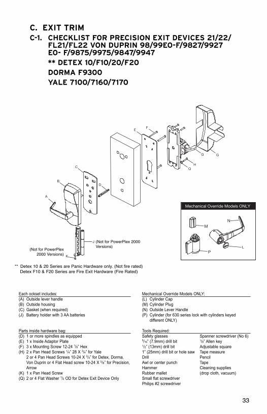
C. EXIT TRIMC-1. CHECKLIST FOR PRECISION EXIT DEVICES 21/22/
FL21/FL22 VON DUPRIN 98/99EO-F/9827/9927 EO- F/9875/9975/9847/9947** DETEX 10/F10/20/F20DORMA F9300YALE 7100/7160/7170
�� �������� �� ��� � �����������
�� �������� �� ��� � �����������
Mechanical Override Models ONLY
A
K
B
C
D
Q H
G G
E F
L
J
P
MN
(Not for PowerPlex2000 Versions)
(Not for PowerPlex 2000Versions)
** Detex 10 & 20 Series are Panic Hardware only. (Not fire rated)Detex F10 & F20 Series are Fire Exit Hardware (Fire Rated)
Each ockset includes:(A) Outside lever handle(B) Outside housing(C) Gasket (when required)(J) Battery holder with 3 AA batteries
Parts inside hardware bag:(D) 1 or more spindles as equipped(E) 1 x Inside Adaptor Plate(F) 3 x Mounting Screw 12-24 1/8” Hex(H) 2 x Pan Head Screws 1/4” 28 X 3/4” for Yale
2 or 4 Pan Head Screws 10-24 X 3/4” for Detex, Dorma,Von Duprin or 4 Flat Head screw 10-24 X 5/8” for Precision,Arrow
(K) 1 x Pan Head Screw(Q) 2 or 4 Flat Washer 1/2 OD for Detex Exit Device Only
Mechanical Override Models ONLY:(L) Cylinder Cap(M) Cylinder Plug(N) Outside Lever Handle(P) Cylinder (for 630 series lock with cylinders keyed
different ONLY)
Tools Required:Safety glasses Spanner screwdriver (No 6)5/16” (7.9mm) drill bit 1/8” Allen key1/2” (13mm) drill bit Adjustable square1” (25mm) drill bit or hole saw Tape measureDrill PencilAwl or center punch TapeHammer Cleaning suppliesRubber mallet (drop cloth, vacuum)Small flat screwdriverPhilips #2 screwdriver

34
C-2. PREPARE THE DOOR FOR THE APPROPRIATE EXIT DEVICE
1. Choose the drilling template of the lock for the exit device to be assembled on the door.
2. Mark the desired handle height on the edge of the door. (see Fig.1)
3. Mark the backset vertical line on each side of the door. Consult the exit device manufacturer’s instructions for the correct backset. The backset shown on the paper template is for reference only. use exit device backset.
Note: Respect all applicable building codes regarding the handle height of the lock and positioning of the bar.
4. Position the drilling template on the inside of the door aligning the door handle height mark and backset vertical line mark with the lines on the template. Mark the door for the holes position.
5. Drill holes to diameters specified on the drilling templates.
Drill the holes in the door required for the exit device according to the manufacturer’s instructions.
Note: Drill from both sides of the door to prevent unsightly damage. Refer to template for drill size and depths.
3 through holes
From the inside, counter bore 5/16 dia. X 3/4 Deep See Drilling Template
2 or 4 Holes
Backset Vertical Line
Inside of Door
4
3
4
Fig. 1
Fig. 27/8”
7/8
35
6
p
I
J
K
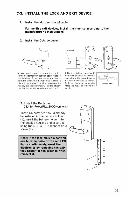
C-3. INSTALL THE LOCK AND EXIT DEVICE
1. Install the Mortise (if applicable)
For mortise exit devices, install the mortise according to the manufacturer’s instructions
2. Install the Outside Lever
6
Assemble the lever on the outside housing, in the horizontal rest position appropriate to the handing of the door as shown. Simply push the lever onto the tube until it clicks in place. If more force is required to engage the handle, use a rubber mallet. Test the attach-ment of the handle by pulling smartly on it.
F
The lever is field reversible. If the handing is incorrect, insert a small pick or flat screwdriver in the hole in the hub as shown. Gently pry back the spring clip inside the hub, and remove the handle.
A B
I
Access Hole
cutaway view
A. Assemble the lever on the outside housing,in the horizontal rest position appropriate tothe handing of the door as shown. Simplypush the lever onto the tube until it clicks inplace. If more force is required to engage thehandle, use a rubber mallet. Test the attach-ment of the handle by pulling smartly on it.
B. The lever is field reversible. Ifthe handing is incorrect, insert asmall pick or flat screwdriver inthe hole in the hub as shown.Gently pry back the spring clipinside the hub, and remove thehandle.
3. Install the Batteries(Not for PowerPlex 2000 versions)
Three AA batteries should alreadybe installed in the battery holder(J). Insert the battery holder intothe outside housing and secure itusing the 6-32 X 3/8” spanner drivescrew (K).
Note: If the lock makes a continu-ous buzzing noise or the red LEDlights continuously, reset theelectronics by removing the bat-tery holder for ten seconds, thenreinsert it.
36
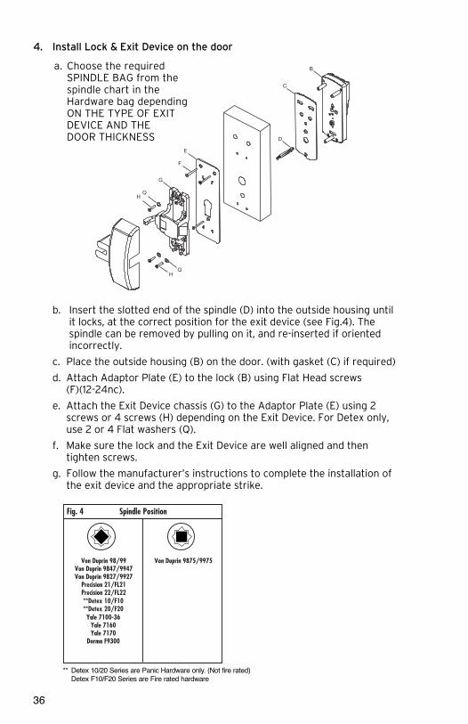
4. Install Lock & Exit Device on the door
b. Insert the slotted end of the spindle (D) into the outside housing until it locks, at the correct position for the exit device (see Fig.4). The spindle can be removed by pulling on it, and re-inserted if oriented incorrectly.
c. Place the outside housing (B) on the door. (with gasket (C) if required)
d. Attach Adaptor Plate (E) to the lock (B) using Flat Head screws (F)(12-24nc).
e. Attach the Exit Device chassis (G) to the Adaptor Plate (E) using 2 screws or 4 screws (H) depending on the Exit Device. For Detex only, use 2 or 4 Flat washers (Q).
f. Make sure the lock and the Exit Device are well aligned and then tighten screws.
g. Follow the manufacturer’s instructions to complete the installation of the exit device and the appropriate strike.
HQ
D
C
B
G
Q H
E
F
a. Choose the required SPINDLE BAG from the spindle chart in the Hardware bag dependingON THE TYPE OF EXIT DEVICE AND THE DOOR THICKNESS
In
Attach Adaptor Plate (E) to the lock (B) using 3 Flat Head screw (F)(12-2
Attach the Exit Device chassis (G) to the Adaptor Plate (E) using 2 screws or 4
Make sure the lock and the Exit Device are well aligned and then tighten s
Follow the manufacturer’s instructions to complete the installation of the exit d
Spindle Position
Von Duprin 98/99Von Duprin 9847/9947Von Duprin 9827/9927
Precision 21/FL21Precision 22/FL22
Arrow S3888**Detex 10/F10**Detex 20/F20
**Detex V40Yale 7100-36
Yale 7160Yale 7170
Dorma F9300
Von Duprin 9875/9975Arrow S1908/S3908Arrow S1708/S3708Arrow S1808/S3808
Fig. 4
In
Attach Adaptor Plate (E) to the lock (B) using 3 Flat Head screw (F)(12-2
Attach the Exit Device chassis (G) to the Adaptor Plate (E) using 2 screws or 4
Make sure the lock and the Exit Device are well aligned and then tighten s
Follow the manufacturer’s instructions to complete the installation of the exit d
**Detex 10/F10**Detex 20/F20
*
In
Attach Adaptor Plate (E) to the lock (B) using 3 Flat Head screw (F)(12-2
Attach the Exit Device chassis (G) to the Adaptor Plate (E) using 2 screws or 4
Make sure the lock and the Exit Device are well aligned and then tighten s
Follow the manufacturer’s instructions to complete the installation of the exit d
Yale 7100-36
Yale 7160Yale 7170
Dorma F9300
V
** Detex 10/20 Series are Panic Hardware only. (Not fire rated)Detex F10/F20 Series are Fire rated hardware

37
D. INSTALLING OUTSIDE LEVER ON NON-MECHANICAL OVERRIDE
Assemble the lever on the outside housing in the hori-zontal rest position appropriate to the handing of thedoor. Simply push the lever onto the tube until it clicksin place. If more force is required, use a rubber mallet. Test the attachment ofthe handle by pulling on it to make sure it is securely fastened.
E. REVERSING THE OUTSIDE LEVER FOR SERIES WITHOUT MECHANICAL OVERRIDE
The lever is field reversible. If the handing is incorrect, insert a small pick or flat screwdriver in the hole in the hub as shown. Gentlypry back the spring clip inside the hub, and removethe handle.

38
F. INSTALLING OPTIONAL K-I-L KEY OR BESTREMOVABLE CORE OVERRIDE AND OUTSIDE LEVER
F-1 Upon unpacking, the lock housing with mechanicaloverride should look like the diagram below with:
• The small indents (i) on the cross of the override shaft (m) in line horizontally
• The plastic washer (c) on the drive tube
• The lever catch (f) in the out position
• Cylinder (j) and 2 keys (n) (included in thehardware bag)
• Shaft override tool (o) (included in thehardware bag)
F-2 Using the override shaft tool (o), turn the overrideshaft clockwise until it stops so that the two smallindents on the cross are now vertically in line.
F-3 Push in the lever catch (f) firmly.
F-4 Insert the cylinder (j) into the lever handle (h).
Note: For Best Removable Core, use Steps F-5, F-6 and F-7, then proceed to F-10 and continue. For Optional K-I-L Key, skip ahead to F-8 and proceed as normal.
For Best Removable Core
F-5 Insert 6-pin Best adapter (thicker) into 6-pin interchangeable core or insert 7-pin Best adapter (thinner) into 7-pin interchangeable core. Insert theadapter until it makes contact with the removable core.
F-6 Using the control key, assemble the removable core with its adapter into the lever. Remove control key.
F-7 Insert the change key into the removablecore.
f
7-pin
adapterThinner
adapterThicker
6-pin
(j)
(o)
h
j
(f)
(i)
(m)
(c, d) (n)
39
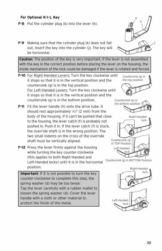
For Optional K-I-L Key
F-8 Put the cylinder plug (k) into the lever (h).
F-9 Making sure that the cylinder plug (k) does not fallout, insert the key into the cylinder (j). The key willbe horizontal.
Caution: The position of the key is very important. If the lever is not assembledwith the key in the correct position before placing the lever on the housing, theinside mechanism of the lock could be damaged if the lever is rotated and forced.
F-10 For Right-Handed Levers: Turn the key clockwise untilit stops so that it is in the vertical position and thecountersink (g) is in the top position. For Left-Handed Levers: Turn the key clockwise untilit stops so that it is in the vertical position and thecountersink (g) is in the bottom position.
F-11 Fit the lever handle (h) onto the drive tube. It should rest approximately 1⁄16" (2 mm) from the body of the housing. If it can’t be pushed that closeto the housing, the lever catch (f) is probably notpushed in. Push it in. If the lever catch (f) is stuck,the override shaft is in the wrong position. Thetwo small indents on the cross of the override shaft must be vertically aligned.
F-12 Press the lever firmly against the housing while turning the key counter-clockwise (this applies to both Right-Handed and Left-Handed locks) until it is in the horizontalposition.
Important: If it is not possible to turn the key counter-clockwise to complete this step, the spring washer (d) may be too tense: Tap the lever carefully with a rubber mallet to loosen the spring washer (d). Cover the lever handle with a cloth or other material to protect the finish of the metal.
Right-Handedlock
Countersink (g)in TOP Position
Countersink (g) in BOTTOM Position
Left-Handedlock
Right-Handedlock
Left-Handedlock
h
j
k
Countersink (g) inthe top position
Countersink (g) inthe bottom position

40
F-13 Remove the key. The lock will look as shown at right.
F-14 Gently check the rotation of the lever handle. It should easily rotate approximately 45º.
Troubleshooting: If you have assembled the lever and housing with the key in the wrong position, the key will getstuck. To remove the key, turn it so that it is in the verticalposition and insert a small flat screwdriver into the holeunder the lever handle to push the lever catch in (f). Remove key. If it is still stuck, turn the key clockwise untilit stops to the horizontal position and push the Lever Catch in again with the small screwdriver. Remove key.
Troubleshooting: Right-Handed Lock: Turn the lever handle clockwise withoutforcing it. If it stops at approximately 15º, it was not assembled correctly. Donot try to force it to turn - this will damage the inside mechanism of the lock.Release the lever handle. Insert the small screwdriver into the small hole on the underside of the lever handle and push in the lever catch.
Re-do steps in section D
Left-Handed Lock: Turn the lever handle counter-clockwise without forcing. Thedrive hub should not rotate when the lever handle is turned. If it does, it was notassembled correctly. Release the lever handle. Insert the small screwdriver intothe small hole on the underside of the lever handle and push in the lever catch.
Re-do steps in section D
F-15 Using the 5/64” Allen Key, tighten the set screw while pushing the lever against the plastic washer to remove the lever play.
G. TESTING THE OPERATION OF THE OUTSIDE LEVERG-1 Verify that the lever has been correctly attached to the housing:
a. Remove key.
b. Insert a small flat screwdriver into the hole on the underside of the leverhandle and push in the lever catch.
c. Pull on the lever.You should not be able to remove the lever. If the lever comes off of thehousing, the lock is not assembled correctly. Return to steps in section Dand repeat this verification process.
Right-Handed lock
Left-Handedlock

41
G-2 Test the Movement of the Lever (without the key in cylinder)a. Turn the lever (h) clockwise for a Right-Handed lockor counter-clockwise for a Left-Handed lock
b. Release the lever slowly. It should return freely to itshorizontal position.
H. TESTING THE MECHANICAL KEY OVERRIDE WITH CHANGE KEY
Important: The Key Override itself does not retract the latch or deadbolt. Do notuse too much force when turning the key as this may damage the unit. To retractthe latch, turn the key clockwise until it stops, release the key and turn the lever.
Note: The lever must stay in the horizontal position whenturning the key (do not try to turn the key while turningthe lever) or the override mechanism will not work.
H-1 Without using the key, turn the lever clockwise forRight-Handed locks or counter-clockwise for Left-Handed locks. The inside drive hub should not rotatewhen the lever turns.
H-2 With the lever (h) in the horizontal position, insertthe key (n) into the cylinder and turn it clockwiseuntil it stops. (This applies to both Right and Left-Handed locks.)
H-3 Let go of the key, and again turn the lever handle(h) clockwise for Right-Handed locks or counter-clockwise for Left-Handed locks. Now the insidedrive hub (b) should rotate in the same direction as the lever handle when it is turned.
Inside drive hubdoes not move
h
n
h
b
h
n
h

42
H-4 Install cap (i) to cover key hole. The cap has a smallgroove on one edge (to allow ease of removal). Thisshould be facing down. Insert bottom snap of cap inlever hole below the cylinder. With a small screw-driver, push top snap of cap down while pushing thecap into place.
H-5 To remove the cap (i), insert a small flat screwdriverinto this groove and gently pry the cap off,being careful not to damage it. Cover the bottom of the lever to protect the finish from being scratched through the process ofremoving the cap.
I. CHANGING KEY-IN-LEVER LOCK CYLINDERSI-1 Loosen the set screw to free the lever (just
1/4 to 1/2 turn).
I-2 Remove the cap from the outside lever (h).
I-3 Insert key (n).
I-4 Turn the key clockwise until it stops.
I-5 Release key (n).
I-6 Use a small flat screwdriver to push in the lever catch through the small hole underneath the outside lever
I-7 Pull the outside lever (h) off of the lock housing.Be careful not to lose the cylinder plug (k).If it is difficult to pull the lever, slightly tighten or loosen the set screw
I-8 Replace the old cylinder with the new one in thelever handle. Only the same kind of cylinder with2 grooves in cross in the end of the cylinder plugcan be used on the lock.
I-9 Re-insert the cylinder plug (k).
I-10 While holding the cylinder (j) and plug (k) in place,insert the key.
I-11 Follow steps F-10 to F-14 and Test as per stepsG and H.
2 Groovesin cross
j
k
h
h
h
Hole below cylinder
Bottom snapi (First)
Top snap(Second)
n
i

43
J. CHANGING BEST-TYPE COREJ-1 Use the control key to remove the removable core from the lever
J-2 Remove the adapter from the removable core and reassemble it on thenew removable core.
Note: It is important that the new removable core has the same number ofpins (6 or 7) as the dismounted one. If not, change the adapter to fit the core.
J-3 Check to make sure that the override shaft did not move and that the 2small indents on override shaft are still vertical (see below). Then, using thecontrol key on the new core, assemble the new removable core on the lever.
J-4 Test the locks using Steps G and H.
K. REMOVING AND REASSEMBLING THE OUTSIDE LEVER
K-1 Loosen the set screw to free the lever (just 1/4 to 1/2 turn).
K-2 Insert the change key in the cylinder.
K-3 Turn the key clockwise until it stops (for both right and left-hand locks).
K-4 Release the key.
K-5 Use a small flat screw driver to push in the lever catch through the smallhole underneath the outside lever.
K-6 Pull the outside lever off of the lock housing. Be careful not to lose theadapter.
Important: Assemble the lever, cylinder and lock components before affixing the entire unit to the door.
K-7 Ensure that the two small indents on the cross arenow vertically in line. (The cylinder or override shafttool can be used to turn override shaft.)
K-8 Push in the lever catch (f) firmly.2 indentsvertical
f

44
L. INSTALLING RUBBER BUMPERSL-1 Close the door and apply pressure making
sure the deadlatch (a) rests on the strikeplate (b) as shown. Standing on the frame(door stop) side of the door, check for gapsbetween the door and the frame on thethree sides of the frame (left, right, andtop).
L-2 Mark locations where the gaps areapproximately 3⁄16" (5 mm). Make surethese locations are free from grease anddust. Peel the bumpers (c) from theirprotective backing without touching theadhesive surface and stick them on themarked locations.
Note: Allow 24 hours for adhesive to set before testing. The door may be operated normally during this time.
M. INSTALLING BATTERY PACK (Not for PowerPlex 2000 Versions)
Note: If the lock makes a continuous buzzing noise or the red LED lights continuously, reset the electronics by removing the battery holder for ten seconds, then reinsert it.
M-1 Three AA batteries should already be installed in the battery holder (q).
M-2 Insert the battery holder into the outside housing and secure it using the 6-32 x 5⁄16" (8 mm) screw (r).
c
aCorrect
b
q
r

45
N. TESTING THE OPERATION OF THE LOCKN-1 Rotate inside lever and hold. Ensure that the latch is fully retracted and
flush with the latch faceplate. Release the inside lever; the latch should befully extended.
N-2 For PowerPlex 2000 you need to activate the outside lever 3 to 4 times to power the lock prior
N-3 Enter the factory-set combination: 1,2,3,4,5,6,7,8. You should see a green light and hear a high pitched tone as you push each button. When the lock opens, you will briefly hear the sound of an electronic motor. Rotate outside lever and hold. Ensure that the latch is fully retracted and flush with the latch faceplate. Release the outside lever; the latch should be fully extended. When the lock re-locks, you will again hear the mot or.
N-4 If your product is an E24xx, you will have to generate an access code usingthe web application to test the lock operation.
N-5 With the door open, verify functionality of the mechanical Key Override asdetailed in Section F.

Kaba Access & Data Systems Americas2941 Indiana Avenue Winston-Salem, NC 27105 USATel: 800.849.8324 336.725.1331Fax: 800.346.9640 336.725.3269
www.kaba-adsamericas.com PKG3218 0413
Related Documents