47th International SAMPE Symposium and Exhibition 2002 (Symposium Title: Affordable Materials Technology; Volume 47:2/2:1690-1702) E-Glass/DGEBA/m-PDA Model Composites: Time Dependent Failure in a Brittle Multi-Fiber Composite G. A. Holmes and W. G. McDonough National Institute of Standards and Technology 100 Bureau Drive Stop 8543 Polymers Division, Multiphase Materials Group Gaithersburg, Maryland 20899-8543 ABSTRACT The fiber-direction properties of a unidirectional laminate are generally considered to be fiber- dominated and the elastic modulus may be predicted by the Rule-of-Mixtures approach using the respective Young’s modulus of the constituents. However, the failure behavior has been qualitatively shown to be dependent on the matrix. For example, Bader in 1968 noted that composites with brittle matrices and relatively weak fiber-matrix interfacial bonding failed in a brush-like manner, while composites with comparatively strong interfaces failed by propagation of a single crack across the section, with little or no longitudinal splitting. Although the tensile strength in a unidirectional composite is mainly influenced by the fiber strength and fiber volume fraction, Bader concluded that the matrix and fiber-matrix interface influences both the strength and failure mode. Research on 2-D multi-fiber model composites has shown that the nucleation of the critical flaw that induces brittle failure is dependent on the redistribution of stress around the fiber breaks through the viscoelastic matrix. Hence, the nucleation process is time-dependent. In addition, the inter-fiber spacing has been shown to influence the mode of failure after fiber fracture. The implication of these observations on failure initiation, propagation, and energy absorption in unidirectional fibrous composites will be discussed. KEYWORDS: Composite Materials, Failure Analysis, Fracture, Viscoelasticity “This paper is declared a work of the U.S. Government and is not subject to copyright protection in the United States”.

Welcome message from author
This document is posted to help you gain knowledge. Please leave a comment to let me know what you think about it! Share it to your friends and learn new things together.
Transcript
47th International SAMPE Symposium and Exhibition 2002 (Symposium Title: Affordable Materials Technology; Volume 47:2/2:1690-1702)
E-Glass/DGEBA/m-PDA Model Composites: Time Dependent Failure in a Brittle Multi-Fiber Composite
G. A. Holmes and W. G. McDonough
National Institute of Standards and Technology 100 Bureau Drive Stop 8543
Polymers Division, Multiphase Materials Group Gaithersburg, Maryland 20899-8543
ABSTRACT
The fiber-direction properties of a unidirectional laminate are generally considered to be fiber-dominated and the elastic modulus may be predicted by the Rule-of-Mixtures approach using the respective Young’s modulus of the constituents. However, the failure behavior has been qualitatively shown to be dependent on the matrix. For example, Bader in 1968 noted that composites with brittle matrices and relatively weak fiber-matrix interfacial bonding failed in a brush-like manner, while composites with comparatively strong interfaces failed by propagation of a single crack across the section, with little or no longitudinal splitting. Although the tensile strength in a unidirectional composite is mainly influenced by the fiber strength and fiber volume fraction, Bader concluded that the matrix and fiber-matrix interface influences both the strength and failure mode. Research on 2-D multi-fiber model composites has shown that the nucleation of the critical flaw that induces brittle failure is dependent on the redistribution of stress around the fiber breaks through the viscoelastic matrix. Hence, the nucleation process is time-dependent. In addition, the inter-fiber spacing has been shown to influence the mode of failure after fiber fracture. The implication of these observations on failure initiation, propagation, and energy absorption in unidirectional fibrous composites will be discussed. KEYWORDS: Composite Materials, Failure Analysis, Fracture, Viscoelasticity
“This paper is declared a work of the U.S. Government and is not subject to copyright protection in the United States”.
47th International SAMPE Symposium and Exhibition 2002 (Symposium Title: Affordable Materials Technology; Volume 47:2/2:1690-1702)
1. INTRODUCTION Damage accumulation and failure in structural composites is of critical importance when designing structures with composites. From a design perspective, the strength prediction of a material and damage evolution in the material when it is exposed to environmental conditions, temperature fluctuations, stresses are critical parameters that must be quantified in order to predict its service life and usefulness. Unlike traditional materials, which are homogeneous, the multiphase and laminated structure of composites precludes the determination of damage evolution in a simplistic manner. The basic structural element of a fibrous composite is the unidirectional lamina, where parallel fibers are embedded in a matrix. In constructing a fibrous composite, the laminae are stacked and oriented in different directions depending on the predicted loads on the structure. The response of the composite to these loads is assessed by classical lamination theory. The fiber-direction properties of a uniaxial lamina are generally considered to be fiber-dominated and the elastic modulus may be predicted accurately by the rule-of-mixtures approach using the properties of the constituent materials. However, the failure behavior, even though the fiber generally has a much high modulus, has been shown qualitatively to be dependent on the matrix. For example, Bader in 1968 (1) noted that composites with brittle matrices and relatively weak fiber-matrix interfacial bonding failed in a brush-like manner, while composites with comparatively strong interfaces failed by propagation of a single crack across the section, with little or no longitudinal splitting. Although the tensile strength in a uniaxial composite is mainly influenced by the fiber strength and fiber volume fraction, Bader concluded that the matrix and fiber-matrix interface influences the failure mode of the composite and has some impact on composite strength. In 1991, reseach by Drzal et al. (2) on glass fiber composites showed that an epoxy-compatible “sizing” used to promote adhesion and environmental stability at the fiber-matrix interphase produced a composite with higher modulus and a greater tensile strength. However, the composite exhibited lower fracture toughness when compared to composites made with bare E-glass fibers. Consistent with the latter result, the failure mode of the uniaxial lamina when tested by flexural loading in the fiber direction changed with the incorporation of the “sizing”. Failure in the bare E-glass composite proceeded by fiber bundle breakage with delamination along the surface of the specimen (quasi-ductile or gradual failure). Incorporation of the “sizing” changed the failure mode to brittle type failure that included, in addition to the previous failure modes, matrix cracks that extended through the specimen thickness. Qualitatively, Drzal connected the composite failure modes, to changes in failure behavior found at the fiber-matrix interphase during testing of single fiber composite specimens. More recently, experiments (3) have shown the effect of the fiber sizing on its strength and failure behavior of hybrid glass-carbon fiber composite. Within the last decade, computational programs designed to predict composite failure behavior have begun to incorporate interphase properties in an attempt to improve their predictive capability. (4-7) Based on his research, Reifsnider made the following comment:
47th International SAMPE Symposium and Exhibition 2002 (Symposium Title: Affordable Materials Technology; Volume 47:2/2:1690-1702)
“It is found that property variations in the interphase have a distinct effect on the local stresses. This is significant, considering the fact that local stresses play an important role in controlling the structural performance of a composites.”
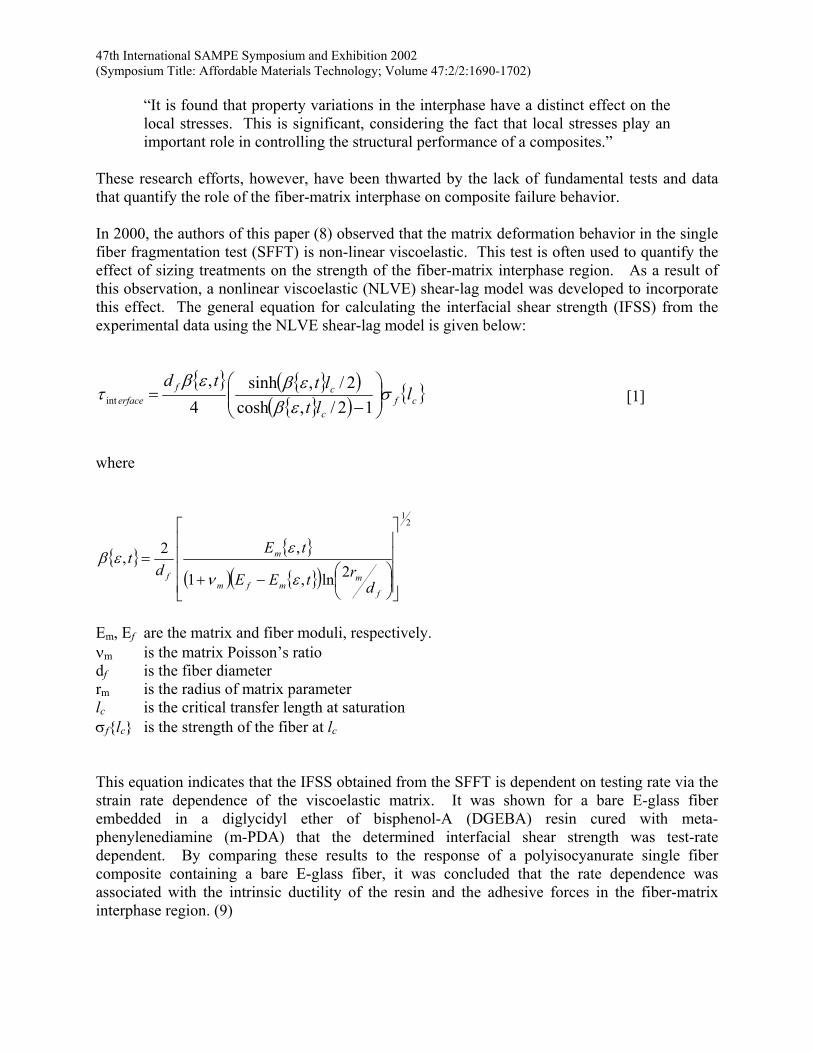
These research efforts, however, have been thwarted by the lack of fundamental tests and data that quantify the role of the fiber-matrix interphase on composite failure behavior. In 2000, the authors of this paper (8) observed that the matrix deformation behavior in the single fiber fragmentation test (SFFT) is non-linear viscoelastic. This test is often used to quantify the effect of sizing treatments on the strength of the fiber-matrix interphase region. As a result of this observation, a nonlinear viscoelastic (NLVE) shear-lag model was developed to incorporate this effect. The general equation for calculating the interfacial shear strength (IFSS) from the experimental data using the NLVE shear-lag model is given below:
{ } { }( ){ }( ) { }cf
c
cferface l
ltlttd
σεβ
εβεβτ
−
=12/,cosh
2/,sinh4
,int [1]
where
{ } { }
( ) { }( )
21
2ln,1
,2,
−+
=
f
mmfm
m
fd
rtEE
tEd
tεν
εεβ
Em, Ef are the matrix and fiber moduli, respectively. νm is the matrix Poisson’s ratio df is the fiber diameter rm is the radius of matrix parameter lc is the critical transfer length at saturation σf{lc} is the strength of the fiber at lc This equation indicates that the IFSS obtained from the SFFT is dependent on testing rate via the strain rate dependence of the viscoelastic matrix. It was shown for a bare E-glass fiber embedded in a diglycidyl ether of bisphenol-A (DGEBA) resin cured with meta-phenylenediamine (m-PDA) that the determined interfacial shear strength was test-rate dependent. By comparing these results to the response of a polyisocyanurate single fiber composite containing a bare E-glass fiber, it was concluded that the rate dependence was associated with the intrinsic ductility of the resin and the adhesive forces in the fiber-matrix interphase region. (9)
47th International SAMPE Symposium and Exhibition 2002 (Symposium Title: Affordable Materials Technology; Volume 47:2/2:1690-1702)
Since most uniaxial laminae used in structural composites typically exhibit brittle failure, reconciling the need for a viscoelastic shear-lag model in the computation of uniaxial laminae strength and failure behavior is problematic. The brittle failure exhibited by typical structural composites has lead most researchers to use the simpler and time independent elastic and elastic-perfectly plastic constitutive laws to quantify the behavior of the matrix in composites materials. Since it has been shown previously that the matrix influences the strength and failure behavior of laminate composites, this paper will focus on how the non-linear viscoelastic behavior of the matrix may influence the failure process. In this initial study, 2-D multi-fiber arrays are tested to assess the fundamentals of composite failure initiation and crack propagation.
2. EXPERIMENTAL 2.1 Fiber-Preparation. The E-glass fibers used in this investigation were coated with 11-aminoundecyl silane (11-AUS). This silane has the same functional group for bonding to epoxy resin as γ-aminopropyl trichlorosilane (γ-APTCS) and γ-aminopropyl trialkoxysilane (γ-APTAS), where the alkoxy group is most often methoxy (γ-APTMS) or ethoxy (γ-APTES). 11-AUS, γ-APTCS, and γ-APTMS were used in a larger study to quantify the mechanical response of the fiber interphase-matrix interphase interface to fiber fracture and covalent bonding. The synthesis of the relevant compounds can be found in that research.(10) A 30 cm long tow was cut from a spool of E-glass fibers (from Owens-Corning,∗ average fiber diameter of 15 mm) previously shown to be bare with no processing aids by X-ray photoelectron spectroscopy (XPS). (9) The tow was washed with acetone (spectrophotometric grade) and vacuum-dried at 100 oC for 2 h and cooled prior to use. The washed E-glass fibers were coated with 11-bromoundecyl trichlorosilane (11-BrUTCS) by dissolving 0.3 % mass fraction of 11-BrUTCS into hexadecane. The acetone-cleaned fibers were immediately immersed in the silane solution. The vial was then placed in an oven and heated to (40 to 50) oC for (4 to 6) h. The coated fibers were then withdrawn from the solution and carefully rinsed with methylene chloride, followed by acetone. The bromine groups on the 11-BrUTCS treated E-glass fibers were then converted to an azide group by placing the treated fibers in a supersaturated solution of NaN3 in dry N,N-dimethylformamide (1.5 g in 100 ml) with continuous stirring. After 24 h the azide-terminated fibers were rinsed with distilled water and converted to amino-terminated fibers by placing the fibers for 24 h in a lithium aluminum hydride solution (0.2 mol/L in tetrahydrofuran). The amine-terminated fibers were then placed in a 5 % mass fraction of hydrochloric acid solution for 5 h to complete the hydrolysis of the aluminum complex. The fibers were then rinsed with distilled water, followed by acetone, and then placed in triethylamine for 24 h to convert the terminal –NH3
+ groups into –NH2 groups. The coated surfaces were then dried for 1 h.
∗ Certain commercial materials and equipment are identified in this paper to specify adequately the experimental procedure. In no case does such identification imply recommendation or endorsement by the National Institute of Standards and Technology, nor does it imply necessarily that the product is the best available for the purpose.
47th International SAMPE Symposium and Exhibition 2002 (Symposium Title: Affordable Materials Technology; Volume 47:2/2:1690-1702)
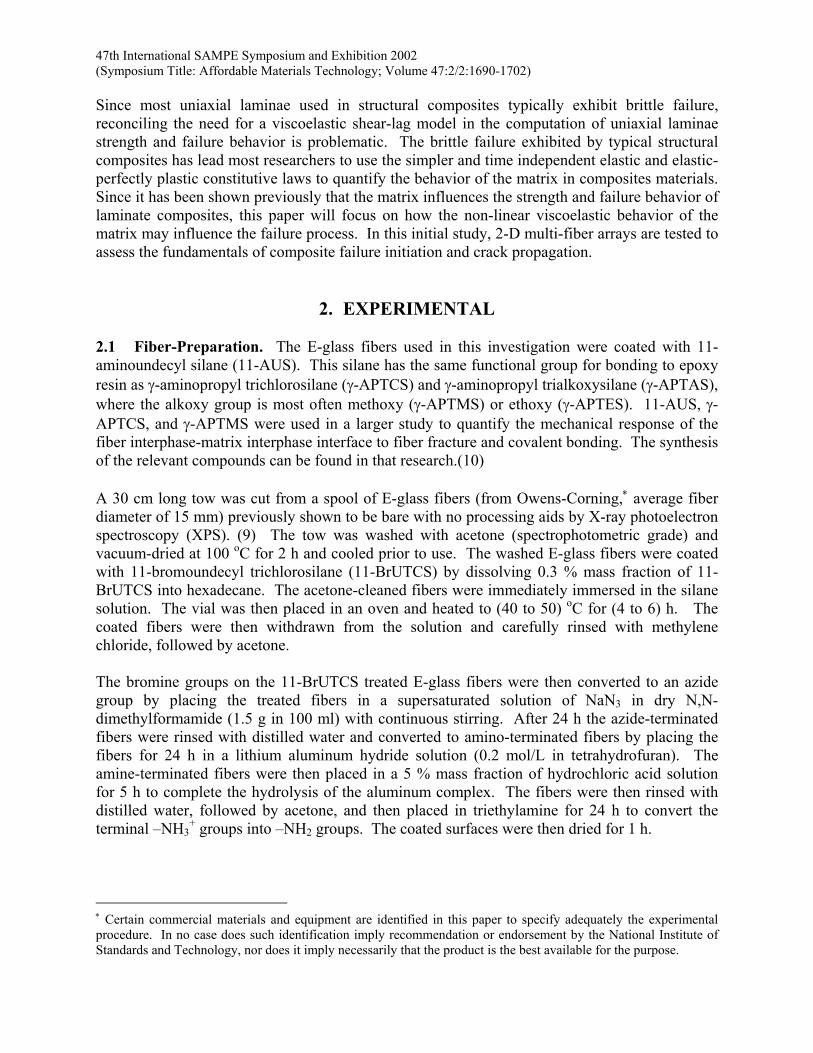
2.2 Multi-Fiber Fragmentation Test (MFFT) Specimen Preparation. The molds for preparing SFFT specimens were made with silicon rubber (General Electric) following the procedure described by Drzal and Herrera-Franco [11]. All molds were post cured at 150 °C and rinsed with acetone prior to use. E-glass filaments were then placed on a multi-fiber-positioner (MFP) originally described by Wagner and Steenbakkers.(12) Using the MFP, a planar array of eight fibers were placed within 3 fiber diameters of each other. The fibers were then aligned and suspended into the silicone molds. The fibers were temporarily fixed in place by pressing them onto double-stick tape. Small strips of double-stick tape were placed over each set of fiber ends to hold them in place until the fiber was permanently mounted with 5-min epoxy (see Figure 1).
SILICON RUBBER
GLASSFIBERS
EPOXY GLUE
Figure 1. Molds for preparing SFFT specimens.
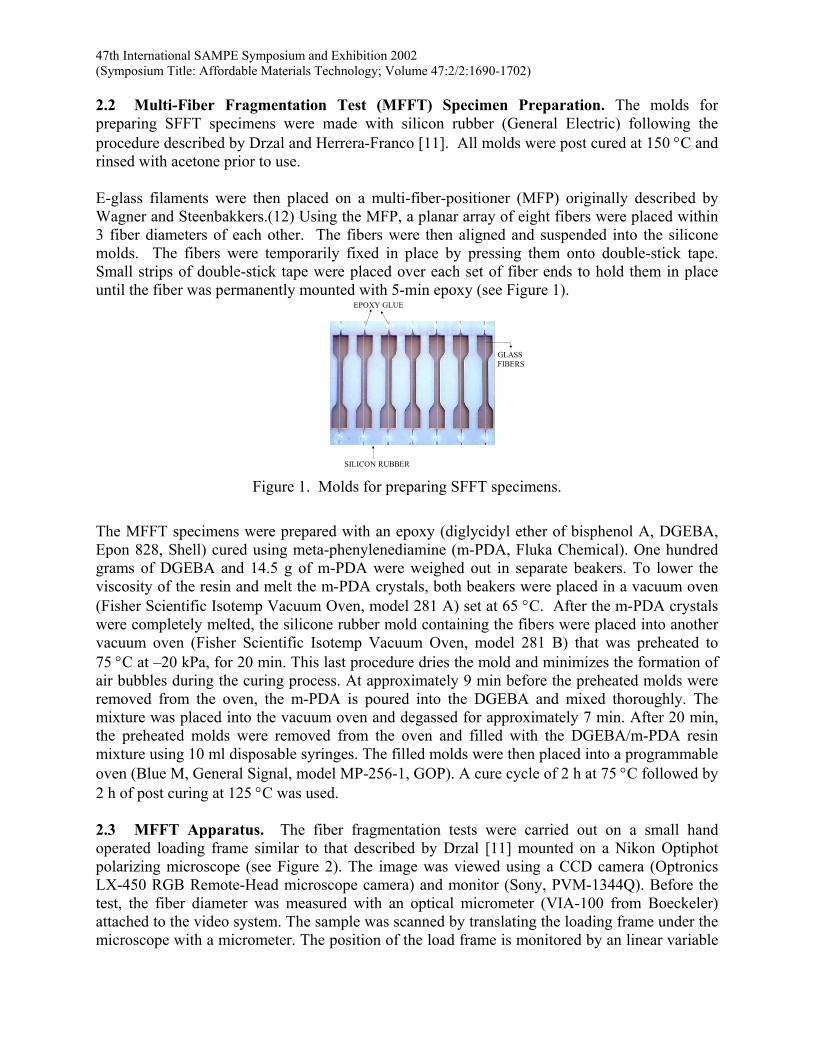
The MFFT specimens were prepared with an epoxy (diglycidyl ether of bisphenol A, DGEBA, Epon 828, Shell) cured using meta-phenylenediamine (m-PDA, Fluka Chemical). One hundred grams of DGEBA and 14.5 g of m-PDA were weighed out in separate beakers. To lower the viscosity of the resin and melt the m-PDA crystals, both beakers were placed in a vacuum oven (Fisher Scientific Isotemp Vacuum Oven, model 281 A) set at 65 °C. After the m-PDA crystals were completely melted, the silicone rubber mold containing the fibers were placed into another vacuum oven (Fisher Scientific Isotemp Vacuum Oven, model 281 B) that was preheated to 75 °C at –20 kPa, for 20 min. This last procedure dries the mold and minimizes the formation of air bubbles during the curing process. At approximately 9 min before the preheated molds were removed from the oven, the m-PDA is poured into the DGEBA and mixed thoroughly. The mixture was placed into the vacuum oven and degassed for approximately 7 min. After 20 min, the preheated molds were removed from the oven and filled with the DGEBA/m-PDA resin mixture using 10 ml disposable syringes. The filled molds were then placed into a programmable oven (Blue M, General Signal, model MP-256-1, GOP). A cure cycle of 2 h at 75 °C followed by 2 h of post curing at 125 °C was used. 2.3 MFFT Apparatus. The fiber fragmentation tests were carried out on a small hand operated loading frame similar to that described by Drzal [11] mounted on a Nikon Optiphot polarizing microscope (see Figure 2). The image was viewed using a CCD camera (Optronics LX-450 RGB Remote-Head microscope camera) and monitor (Sony, PVM-1344Q). Before the test, the fiber diameter was measured with an optical micrometer (VIA-100 from Boeckeler) attached to the video system. The sample was scanned by translating the loading frame under the microscope with a micrometer. The position of the load frame is monitored by an linear variable
47th International SAMPE Symposium and Exhibition 2002 (Symposium Title: Affordable Materials Technology; Volume 47:2/2:1690-1702)
differential transformer (LVDT) (Trans-Tek, Inc. model 1002-0012) connected to an A-to-D board (Strawberry Tree, Inc.) in a computer. To measure fragment lengths or other points of interest in the sample, the location was aligned with a cross hair in the microscope as seen on the video monitor, and the position of the LVDT was digitized into the computer. The standard uncertainty in relocating a point reproducibly is ± 1.1 µm. The load is also monitored during the experiment using a 2,224 N (500 pounds) load cell connected to a bridge (load cell and AED 9001A bridge, Cooper Instruments). The expected standard fractional uncertainty of the load measurements is 3 % of the load. The bridge is attached to the same computer via a serial connection. A custom program was developed to continuously record changes in the load and displacement.
Figure 2. Schematic of Single Fiber Fragmentation Test Machine
2.4 MFFT Testing Protocol. The MFFT specimen was loaded in tension by the sequential application of step-strains. The average application time of each strain step was (1.1 ± 0.2) s and the average deformation was (14.5 ± 3.1) µm, where the number after the “±” sign represents one standard deviation about the mean value. The delay time between the application of successive step-strains was 10 min. [9]
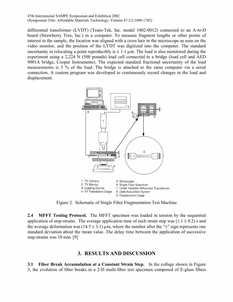
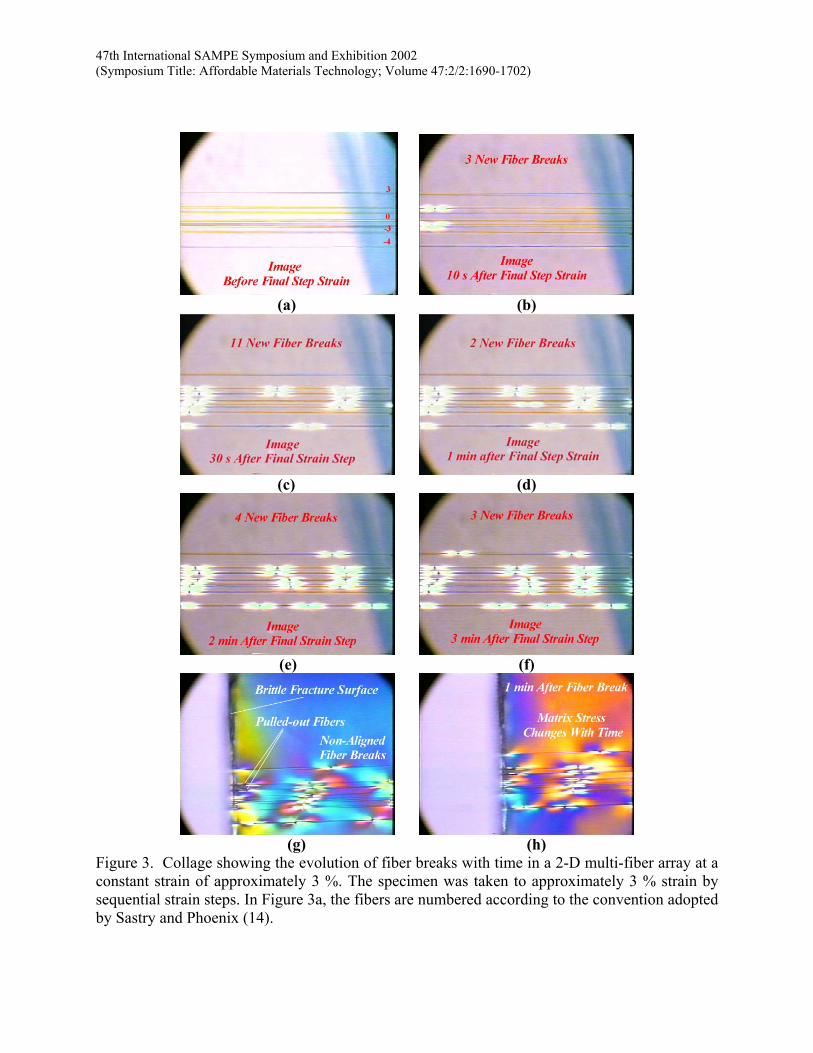
3. RESULTS AND DISCUSSION 3.1 Fiber Break Accumulation at a Constant Strain Step. In the collage shown in Figure 3, the evolution of fiber breaks in a 2-D multi-fiber test specimen composed of E-glass fibers
47th International SAMPE Symposium and Exhibition 2002 (Symposium Title: Affordable Materials Technology; Volume 47:2/2:1690-1702)
embedded in a DGEBA/m-PDA matrix is shown. The E-glass fibers were coated with an amine silane-coupling agent that had been shown to induce matrix cracks during fiber fracture.(13) The approximate 3 % strain in the specimen was obtained by sequential strain steps using the standard 10 min between strain increment testing protocol.(9) Using the nomenclature adopted by Sastry and Phoenix (14), the eight E-glass fibers are numbered from 3 to –4 (see the numbers above selected fibers on the right side of Figure 3a). Three fiber-breaks occur within 10 s after reaching 3 % strain in fibers 2, -1, and –2. These fiber-breaks initiate a cascade of subsequent breaks that occur over a period of approximately 3 min in the test specimen (see Figure 3b to f). Of critical importance in these images is the evolution of the fiber break pattern with increasing time and constant strain.
47th International SAMPE Symposium and Exhibition 2002 (Symposium Title: Affordable Materials Technology; Volume 47:2/2:1690-1702)
(a) (b)
(c) (d)
(e) (f)
(g) (h)
Figure 3. Collage showing the evolution of fiber breaks with time in a 2-D multi-fiber array at a constant strain of approximately 3 %. The specimen was taken to approximately 3 % strain by sequential strain steps. In Figure 3a, the fibers are numbered according to the convention adopted by Sastry and Phoenix (14).
47th International SAMPE Symposium and Exhibition 2002 (Symposium Title: Affordable Materials Technology; Volume 47:2/2:1690-1702)
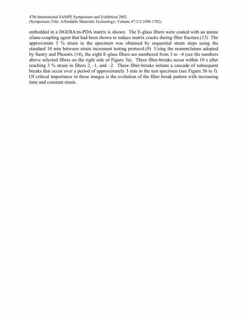
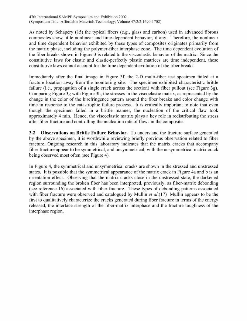
As noted by Schapery (15) the typical fibers (e.g., glass and carbon) used in advanced fibrous composites show little nonlinear and time-dependent behavior, if any. Therefore, the nonlinear and time dependent behavior exhibited by these types of composites originates primarily from the matrix phase, including the polymer-fiber interphase zone. The time dependent evolution of the fiber breaks shown in Figure 3 is related to the viscoelastic behavior of the matrix. Since the constitutive laws for elastic and elastic-perfectly plastic matrices are time independent, these constitutive laws cannot account for the time dependent evolution of the fiber breaks. Immediately after the final image in Figure 3f, the 2-D multi-fiber test specimen failed at a fracture location away from the monitoring site. The specimen exhibited characteristic brittle failure (i.e., propagation of a single crack across the section) with fiber pullout (see Figure 3g). Comparing Figure 3g with Figure 3h, the stresses in the viscoelastic matrix, as represented by the change in the color of the birefringence pattern around the fiber breaks and color change with time in response to the catastrophic failure process. It is critically important to note that even though the specimen failed in a brittle manner, the nucleation of the critical flaw took approximately 4 min. Hence, the viscoelastic matrix plays a key role in redistributing the stress after fiber fracture and controlling the nucleation rate of flaws in the composite. 3.2 Observations on Brittle Failure Behavior. To understand the fracture surface generated by the above specimen, it is worthwhile reviewing briefly previous observation related to fiber fracture. Ongoing research in this laboratory indicates that the matrix cracks that accompany fiber fracture appear to be symmetrical, and unsymmetrical, with the unsymmetrical matrix crack being observed most often (see Figure 4). In Figure 4, the symmetrical and unsymmetrical cracks are shown in the stressed and unstressed states. It is possible that the symmetrical appearance of the matrix crack in Figure 4a and b is an orientation effect. Observing that the matrix cracks close in the unstressed state, the darkened region surrounding the broken fiber has been interpreted, previously, as fiber-matrix debonding (see reference 16) associated with fiber fracture. These types of debonding patterns associated with fiber fracture were observed and catalogued by Mullin et al.(17) Mullin appears to be the first to qualitatively characterize the cracks generated during fiber fracture in terms of the energy released, the interface strength of the fiber-matrix interphase and the fracture toughness of the interphase region.
47th International SAMPE Symposium and Exhibition 2002 (Symposium Title: Affordable Materials Technology; Volume 47:2/2:1690-1702)
(a) (b)
(c) (d)
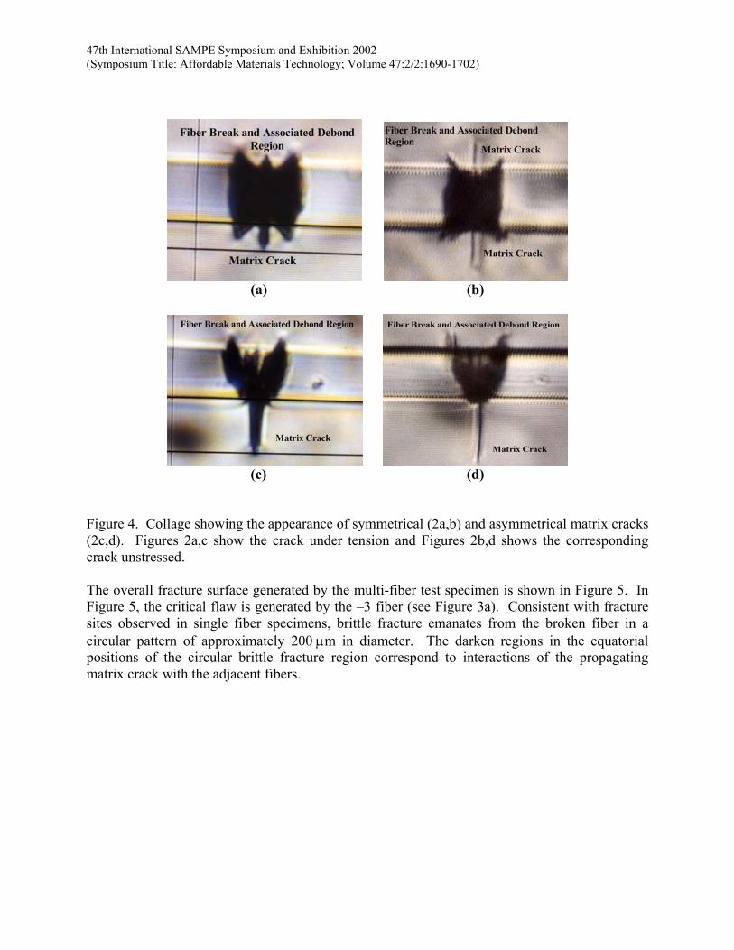
Figure 4. Collage showing the appearance of symmetrical (2a,b) and asymmetrical matrix cracks (2c,d). Figures 2a,c show the crack under tension and Figures 2b,d shows the corresponding crack unstressed. The overall fracture surface generated by the multi-fiber test specimen is shown in Figure 5. In Figure 5, the critical flaw is generated by the –3 fiber (see Figure 3a). Consistent with fracture sites observed in single fiber specimens, brittle fracture emanates from the broken fiber in a circular pattern of approximately 200 µm in diameter. The darken regions in the equatorial positions of the circular brittle fracture region correspond to interactions of the propagating matrix crack with the adjacent fibers.
47th International SAMPE Symposium and Exhibition 2002 (Symposium Title: Affordable Materials Technology; Volume 47:2/2:1690-1702)
Figure 5. Fracture surface of multifiber test specimen. The fiber break that initiated the critical flaw generated a brittle fracture surface approximately 200 µm in diameter.
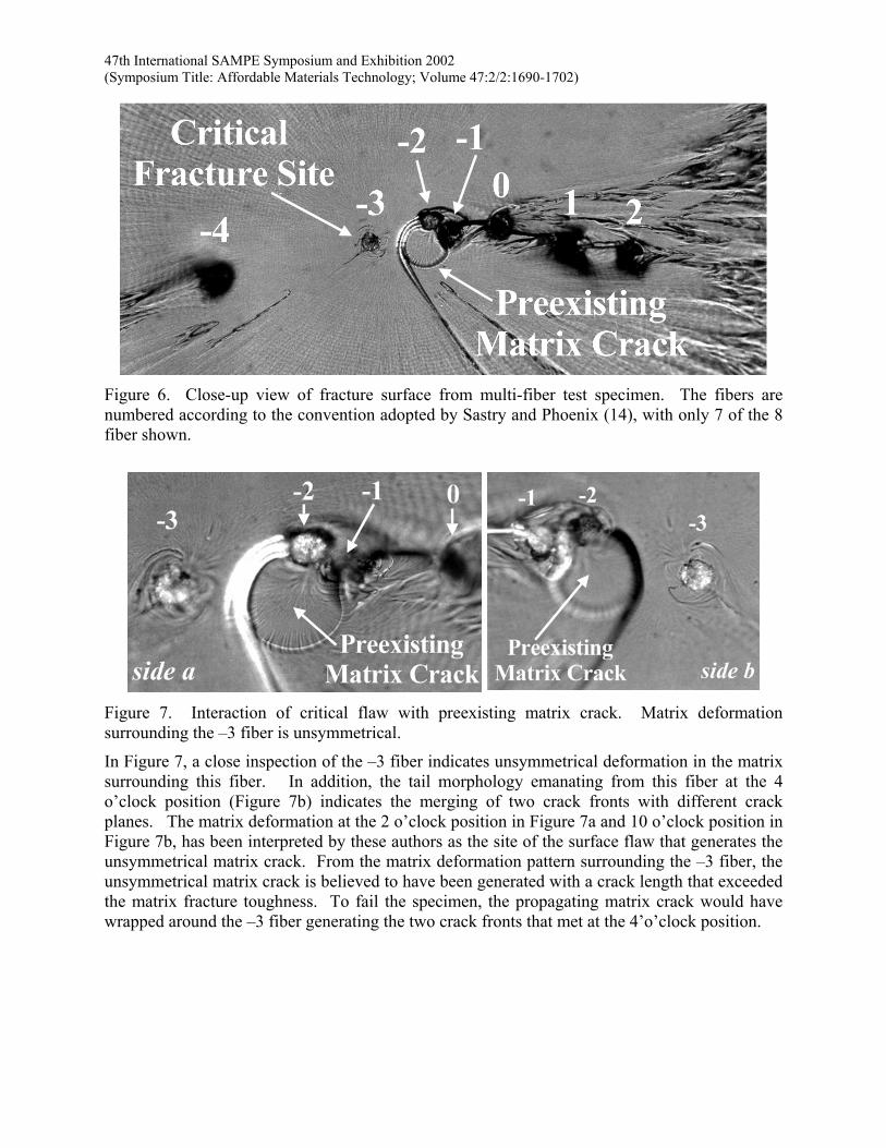
In the dark circular and triangular regions the propagating matrix crack is bifurcated by the adjacent fibers. In the circular region, this bifurcation is caused by the –4 fiber that has a preexisting fiber break approximately 3 fiber diameters away from the crack plane. This distance is a sufficient distance from the propagating crack plane to result in the –4 fiber being pulled out of the resin at its preexisting fiber break site (see Figure 6). The critical flaw generated by the fracture of fiber 3 also interacts with a preexisting matrix crack that was generated prior to complete failure of the specimen by the fracture of the –1 or –2 fiber or both. Observe that the matrix crack is non-symmetrical, suggesting that a surface flaw may have caused the failure of the –1 or –2 fiber. Optical measurements indicate that the plane of the preexisting matrix crack and the critical flaw differ by less than 1 fiber diameter. The imprint of the matrix crack on both sides of the fracture surface (see Figure 7) is consistent with this measurement. The unsymmetrical matrix deformations surrounding the –3 fiber may suggest that the critical flaw originated from a surface flaw on the E-glass fiber.
47th International SAMPE Symposium and Exhibition 2002 (Symposium Title: Affordable Materials Technology; Volume 47:2/2:1690-1702)
Figure 6. Close-up view of fracture surface from multi-fiber test specimen. The fibers are numbered according to the convention adopted by Sastry and Phoenix (14), with only 7 of the 8 fiber shown.
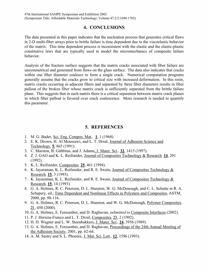
Figure 7. Interaction of critical flaw with preexisting matrix crack. Matrix deformation surrounding the –3 fiber is unsymmetrical.
In Figure 7, a close inspection of the –3 fiber indicates unsymmetrical deformation in the matrix surrounding this fiber. In addition, the tail morphology emanating from this fiber at the 4 o’clock position (Figure 7b) indicates the merging of two crack fronts with different crack planes. The matrix deformation at the 2 o’clock position in Figure 7a and 10 o’clock position in Figure 7b, has been interpreted by these authors as the site of the surface flaw that generates the unsymmetrical matrix crack. From the matrix deformation pattern surrounding the –3 fiber, the unsymmetrical matrix crack is believed to have been generated with a crack length that exceeded the matrix fracture toughness. To fail the specimen, the propagating matrix crack would have wrapped around the –3 fiber generating the two crack fronts that met at the 4’o’clock position.
47th International SAMPE Symposium and Exhibition 2002 (Symposium Title: Affordable Materials Technology; Volume 47:2/2:1690-1702)
4. CONCLUSIONS The data presented in this paper indicates that the nucleation process that generates critical flaws in 2-D multi-fiber arrays prior to brittle failure is time dependent due to the viscoelastic behavior of the matrix. This time dependent process is inconsistent with the elastic and the elastic-plastic constitutive laws that are typically used to model the micromechanics of composite failure behavior. Analysis of the fracture surface suggests that the matrix cracks associated with fiber failure are unsymmetrical and generated from flaws on the glass surface. The data also indicates that cracks within one fiber diameter coalesce to form a single crack. Numerical computation programs generally assume that the cracks grow to critical size with increased deformation. In this resin, matrix cracks occurring in adjacent fibers and separated by three fiber diameters results in fiber pullout of the broken fiber whose matrix crack is sufficiently separated from the brittle failure plane. This suggests that in each matrix there is a critical separation between matrix crack planes in which fiber pullout is favored over crack coalescence. More research is needed to quantify this parameter.
5. REFERENCES
1. M. G. Bader, Sci. Eng. Compos. Mat., 1, 1 (1968). 2. E. K. Drown, H. Al Moussawi, and L. T. Drzal, Journal of Adhesion Science and
Technology, 5, 865 (1991). 3. C. Marston, B. Gabbitas, and J. Adams, J. Mater. Sci., 32, 1415 (1997). 4. Z. J. GAO and K. L. Reifsnider, Journal of Composites Technology & Research, 14, 201
(1992). 5. K. L. Reifsnider, Composites, 25, 461 (1994). 6. K. Jayaraman, K. L. Reifsnider, and R. E. Swain, Journal of Composites Technology &
Research, 15, 3 (1993). 7. K. Jayaraman, K. L. Reifsnider, and R. E. Swain, Journal of Composites Technology &
Research, 15, 14 (1993). 8. G. A. Holmes, R. C. Peterson, D. L. Hunston, W. G. McDonough, and C. L. Schutte in R. A.
Schapery, ed., Time Dependent and Nonlinear Effects in Polymers and Composites, ASTM, 2000, pp. 98-116.
9. G. A. Holmes, R. C. Peterson, D. L. Hunston, and W. G. McDonough, Polymer Composites, 21, 450 (2000).
10. G. A. Holmes, E. Feresenbet, and D. Raghavan, submitted to Composite Interfaces (2002). 11. P. J. Herrera-Franco and L. T. Drzal, Composites, 23, 2 (1992). 12. H. D. Wagner and L. W. Steenbakkers, J. Mater. Sci., 24, 3956 (1989). 13. G. A. Holmes, E. Feresenbet, and D. Raghavan, Proceedings of the 24th Annual Meeting of
the Adhesion Society, 2001, pp. 62-64. 14. A. M. Sastry and S. L. Phoenix, J. Mat. Sci. Lett., 12, 1596 (1993).
47th International SAMPE Symposium and Exhibition 2002 (Symposium Title: Affordable Materials Technology; Volume 47:2/2:1690-1702)
15. R. A. Schapery and C. T. Sun, Time Dependent and Nonlinear Effects in Polymers and Composites, American Society for Testing and Materials, Philadelphia, PA, 2000
16. G. A. Holmes, R. C. Peterson, D. L. Hunston, and W. G. McDonough, submitted to Polymer Composites (2002).
17. J. Mullin, J. M. Berry, and A. Gatti, Journal of Composite Materials, 2, 82 (1968).
Related Documents