Designation: E 2230 – 02 An American National Standard Standard Practice for Thermal Qualification of Type B Packages for Radioactive Material 1 This standard is issued under the fixed designation E 2230; the number immediately following the designation indicates the year of original adoption or, in the case of revision, the year of last revision. A number in parentheses indicates the year of last reapproval. A superscript epsilon (e) indicates an editorial change since the last revision or reapproval. 1. Scope 1.1 This practice defines detailed methods for thermal qualification of “Type B” radioactive materials packages under Title 10, Code of Federal Regulations, Part 71 (10CFR71) in the United States or, under International Atomic Energy Agency Regulation TS-R-1. Under these regulations, packages transporting what are designated to be Type B quantities of radioactive material shall be demonstrated to be capable of withstanding a sequence of hypothetical accidents without significant release of contents. 1.2 This standard does not purport to address all of the safety concerns, if any, associated with its use. It is the responsibility of the user of this standard to establish appro- priate safety and health practices and determine the applica- bility of regulatory limitations prior to use. 1.3 This standard is used to measure and describe the response of materials, products, or assemblies to heat and flame under controlled conditions, but does not by itself incorporate all factors required for fire hazard or fire risk assessment of the materials, products, or assemblies under actual fire conditions. 2. Referenced Documents 2.1 ASTM Standards: E 176 Terminology of Fire Standards 2 IEEE/ASTM SI-10 International System of Units (SI) The Modernized Metric System 2.2 Federal Standard: Title 10, Code of Federal Regulations, Part 71 (10CFR71), Packaging and Transportation of Radioac- tive Material, United States Government Printing Office, 2000 2.3 Nuclear Regulatory Commission Standards: Standard Format and Content of Part 71 Applications for Approval of Packaging of Type B Large Quantity and Fissile Radioactive Material, Regulatory Guide 7.9, United States Nuclear Regulatory Commission, United States Government Printing Office, 1986. Standard Review Plan for Transportation of Radioactive Materials, NUREG-1609, United States Nuclear Regula- tory Commission, United States Government Printing Office, May 1999 2.4 International Atomic Energy Agency Standards: Regulations for the Safe Transport of Radioactive Material, No. TS-R-1, (IAEA ST-1 Revised) International Atomic Energy Agency, Vienna, Austria, 1996 Regulations for the Safe Transport of Radioactive Material, No. ST-2, (IAEA ST-2) International Atomic Energy Agency, Vienna, Austria, 1996 2.5 American Society of Mechanical Engineers Standard: Quality Assurance Program Requirements for Nuclear Fa- cilities, NQA-1, American Society of Mechanical Engi- neers, New York, 2001 2.6 International Organization for Standards (ISO) Stan- dard: ISO 9000:2000, Quality Management Systems— Fundamentals and Vocabulary, International Organization for Standards (ISO), Geneva, Switzerland, 2000 3. Terminology 3.1 Definitions—For definitions of terms used in this test method refer to the terminology contained in Terminology E 176 and ISO 13943. In case of conflict, the definitions given in Terminology E 176 shall prevail. 3.2 Definitions of Terms Specific to This Standard: 3.2.1 hypothetical accident conditions, n—a series of acci- dent environments, defined by regulation, that a Type B package must survive without significant loss of contents. 3.2.2 insolation, n—solar energy incident on the surface of a package. 3.2.3 normal conditions of transport, n—a range of condi- tions, defined by regulation, that a package must withstand during normal usage. 3.2.4 regulatory hydrocarbon fire, n—a fire environment, one of the hypothetical accident conditions, defined by regu- lation, that a package shall survive for 30 min without significant release of contents. 1 This practice is under the jurisdiction of ASTM Committee E05 on Fire Standards and is the direct responsibility of Subcommittee E05.13 on Large Scale Fire Tests. Current edition approved Aug. 10, 2002. Published October 2002. 2 Annual Book of ASTM Standards, Vol 04.07. 1 Copyright © ASTM International, 100 Barr Harbor Drive, PO Box C700, West Conshohocken, PA 19428-2959, United States.

E 2230 - 02 _RTIYMZA_
Jan 01, 2016
E 2230 - 02 _RTIYMZA_
Welcome message from author
This document is posted to help you gain knowledge. Please leave a comment to let me know what you think about it! Share it to your friends and learn new things together.
Transcript
Designation: E 2230 – 02 An American National Standard
Standard Practice forThermal Qualification of Type B Packages for RadioactiveMaterial 1
This standard is issued under the fixed designation E 2230; the number immediately following the designation indicates the year oforiginal adoption or, in the case of revision, the year of last revision. A number in parentheses indicates the year of last reapproval. Asuperscript epsilon (e) indicates an editorial change since the last revision or reapproval.
1. Scope
1.1 This practice defines detailed methods for thermalqualification of “Type B” radioactive materials packages underTitle 10, Code of Federal Regulations, Part 71 (10CFR71) inthe United States or, under International Atomic EnergyAgency Regulation TS-R-1. Under these regulations, packagestransporting what are designated to be Type B quantities ofradioactive material shall be demonstrated to be capable ofwithstanding a sequence of hypothetical accidents withoutsignificant release of contents.
1.2 This standard does not purport to address all of thesafety concerns, if any, associated with its use. It is theresponsibility of the user of this standard to establish appro-priate safety and health practices and determine the applica-bility of regulatory limitations prior to use.
1.3 This standard is used to measure and describe theresponse of materials, products, or assemblies to heat andflame under controlled conditions, but does not by itselfincorporate all factors required for fire hazard or fire riskassessment of the materials, products, or assemblies underactual fire conditions.
2. Referenced Documents
2.1 ASTM Standards:E 176 Terminology of Fire Standards2
IEEE/ASTM SI-10 International System of Units (SI) TheModernized Metric System
2.2 Federal Standard:Title 10, Code of Federal Regulations, Part 71
(10CFR71),Packaging and Transportation of Radioac-tive Material, United States Government Printing Office,2000
2.3 Nuclear Regulatory Commission Standards:Standard Format and Content of Part 71 Applications for
Approval of Packaging of Type B Large Quantity andFissile Radioactive Material, Regulatory Guide
7.9, United States Nuclear Regulatory Commission,United States Government Printing Office, 1986.
Standard Review Plan for Transportation of RadioactiveMaterials, NUREG-1609, United States Nuclear Regula-tory Commission, United States Government PrintingOffice, May 1999
2.4 International Atomic Energy Agency Standards:Regulations for the Safe Transport of Radioactive Material,
No. TS-R-1, (IAEA ST-1 Revised) International AtomicEnergy Agency, Vienna, Austria, 1996
Regulations for the Safe Transport of Radioactive Material,No. ST-2, (IAEA ST-2) International Atomic EnergyAgency, Vienna, Austria, 1996
2.5 American Society of Mechanical Engineers Standard:Quality Assurance Program Requirements for Nuclear Fa-
cilities, NQA-1, American Society of Mechanical Engi-neers, New York, 2001
2.6 International Organization for Standards (ISO) Stan-dard:
ISO 9000:2000, Quality Management Systems—Fundamentals and Vocabulary, International Organizationfor Standards (ISO), Geneva, Switzerland, 2000
3. Terminology
3.1 Definitions—For definitions of terms used in this testmethod refer to the terminology contained in TerminologyE 176 and ISO 13943. In case of conflict, the definitions givenin Terminology E 176 shall prevail.
3.2 Definitions of Terms Specific to This Standard:3.2.1 hypothetical accident conditions, n—a series of acci-
dent environments, defined by regulation, that a Type Bpackage must survive without significant loss of contents.
3.2.2 insolation, n—solar energy incident on the surface ofa package.
3.2.3 normal conditions of transport, n—a range of condi-tions, defined by regulation, that a package must withstandduring normal usage.
3.2.4 regulatory hydrocarbon fire, n—a fire environment,one of the hypothetical accident conditions, defined by regu-lation, that a package shall survive for 30 min withoutsignificant release of contents.
1 This practice is under the jurisdiction of ASTM Committee E05 on FireStandards and is the direct responsibility of Subcommittee E05.13 on Large ScaleFire Tests.
Current edition approved Aug. 10, 2002. Published October 2002.2 Annual Book of ASTM Standards, Vol 04.07.
1
Copyright © ASTM International, 100 Barr Harbor Drive, PO Box C700, West Conshohocken, PA 19428-2959, United States.
3.2.5 thermal qualification, n—the portion of the certifica-tion process for a radioactive materials transportation packagethat includes the submittal, review, and approval of a SafetyAnalysis Report for Packages (SARP) through an appropriateregulatory authority, and which demonstrates that the packagemeets the thermal requirements stated in the regulations.
3.2.6 Type B package, n—a transportation package that islicensed to carry what the regulations define to be a Type Bquantity of a specific radioactive material or materials.
4. Summary of Practice
4.1 This document outlines four methods for meeting thethermal qualification requirements: qualification by analysis,pool fire testing, furnace testing, and radiant heat testing. Thechoice of the certification method for a particular package isbased on discussions between the package suppliers and theappropriate regulatory authorities prior to the start of thequalification process. Factors that influence the choice ofmethod are package size, construction and cost, as well ashazards associated with certification process. Environmentalfactors such as air and water pollution are increasingly a factorin choice of qualification method. Specific benefits and limi-tations for each method are discussed in the sections coveringthe particular methods.
4.2 The complete hypothetical accident condition sequenceconsists of a drop test, a puncture test, and a 30-min hydro-carbon fire test, commonly called a pool fire test, on thepackage. Submersion tests on undamaged packages are alsorequired, and smaller packages are also required to survivecrush tests that simulate handling accidents. Details of the testsand test sequences are given in the regulations cited. Thisdocument focuses on thermal qualification, which is similar inboth the U.S. and IAEA regulations. A summary of importantdifferences is included as Appendix X3 to this document. Theoverall thermal test requirements are described generally inPart 71.73 of 10CFR71 and in Section VII of TS-R-1.Additional guidance on thermal tests is also included in IAEAST-2.
4.3 The regulatory thermal test is intended to simulate a30-min exposure to a fully engulfing pool fire that occurs if atransportation accident involves the spill of large quantities ofhydrocarbon fuels from a tank truck or similar vehicle. Theregulations are “mode independent” meaning that they areintended to cover packages for a wide range of transportationmodes such as truck and rail.
5. Significance and Use
5.1 The major objective of this practice is to provide acommon reference document for both applicants and certifica-tion authorities on the accepted practices for accomplishingpackage thermal qualification. Details and methods for accom-plishing qualification are described in this document in morespecific detail than available in the regulations. Methods thathave been shown by experience to lead to successful qualifi-cation are emphasized. Possible problems and pitfalls that leadto unsatisfactory results are also described.
5.2 The work described in this standard practice shall bedone under a quality assurance program that is accepted by theregulatory authority that certifies the package for use. For
packages certified in the United States, ASME NQA-1 shall beused as the basis for the quality assurance (QA) program, whilefor international certification, ISO 9000 usually defines theappropriate program. Note that 10 CFR 71, Subpart H outlinesQA requirements for transportation packages qualified in theU. S. The quality assurance program shall be in place andfunctioning prior to submittal of any information to thecertifying authority.
5.3 The unit system (SI metric or English) used for thermalqualification shall be agreed upon prior to submission ofinformation to the certification authority. If SI units are to bestandard, then use IEEE/ASTM SI-10. Additional units givenin parentheses are for information purposes only.
TEST METHODS
6. Scope
6.1 In preparing a Safety Analysis Report for Packaging(SARP), the normal transport and accident thermal conditionsspecified in 10CFR71 or IAEA TS-R-1 shall be addressed. Forapproval in the United States, reports addressing the thermalissues shall be included in a SARP prepared according to theformat described in Nuclear Regulatory Commission (NRC)Regulatory Guide 7.9. Upon review, a package is consideredqualified if material temperatures are within acceptable limits,temperature gradients lead to acceptable thermal stresses, thecavity gas pressure is within design limits, and safety featurescontinue to function over the entire temperature range. Testinitial conditions vary with regulation, but are intended to givethe most unfavorable normal ambient temperature for thefeature under consideration, and corresponding internal pres-sures are usually at the maximum normal values unless a lowerpressure is shown to be more unfavorable. Depending on theregulation used, the ambient air temperature is in the -29°C(-20°F) to 38°C (100°F) range. Normal transport requirementsinclude a maximum air temperature of 38°C (100°F), insola-tion, and a cold temperature of -40°C (-40°F). Regulations alsoinclude a maximum package surface temperatures for person-nel protection of 50°C (122°F). See Appendix X3 for clarifi-cation of differences between U.S. and international regula-tions.
6.2 Hypothetical accident thermal requirements stated inPart 71.73 or IAEA TS-R-1, Section VII call for a 30 minexposure of the entire container to a radiation environment of800°C (1475°F) with a flame emissivity of 0.9. The surfaceemissivity of the package shall be 0.8 or the package surfacevalue, whichever is greater. With temperatures and emissivitiesstated in the specification, the basic laws of radiation heattransfer permit direct calculation of the resulting radiant heatflux to a package surface. This means that what appears at firstglance to be a flame or furnace temperature specification is inreality a heat flux specification for testing. Testing shall beconducted with this point in mind.
6.3 Two definitions of flame emissivity exist, and thiscauses confusion during the qualification process. Siegel andHowell, 2001, provide the textbook definition for a cloud of hotsoot particles representing a typical flame zone in open poolfires. In this definition the black body emissive power of theflame,sT4, is multiplied by the flame emissivity,e, in order to
E 2230 – 02
2

account for the fact that soot clouds in flames behave as if theyare weak black body emitters. A second definition of flameemissivity, often used for package analysis, assumes that theflame emissivity, e, is the surface emissivity of a large,high-temperature, gray-body surface that both emits and re-flects energy and completely surrounds the package underanalysis. The second definition leads to slightly higher (con-servative) heat fluxes to the package surface, and also leads toa zero heat flux as the package surface reaches the firetemperature. For the first definition, the heat flux falls to zerowhile the package surface is somewhat below the fire tempera-ture. For package qualification, use of the second definition isoften more convenient, especially with computer codes thatmodel surface-to-surface thermal radiation, and is usuallypermitted by regulatory authorities.
6.4 Convective heat transfer from moving air at 800°C shallalso be included in the analysis. Convection correlations shallbe chosen to conform to the surface configuration, that is,vertical or horizonal, flat plate or cylinder, that is used forpackage transport. Typical flow velocities for combustion gasesmeasured in large fires range are in the 1 to 10 m/s range withmean velocities near the middle of that range (see Schneiderand Kent, 1989, Gregory, et al, 1987, and Koski, et al, 1996).No external non-natural cooling of the package after heat inputis permitted after the fire event,, and combustion shall proceeduntil it stops naturally. During the fire, effects of solar radiationare often neglected for analysis and test purposes.
6.5 For purposes of analysis, the hypothetical accidentthermal conditions are specified by the surface heat flux values.Peak regulatory heat fluxes for low surface temperaturestypically range from 55 to 65 kW/m2. Convective heat transferfrom air is estimated from convective heat transfer correla-tions, and contributes of 15 to 20 % of the total heat flux. Thevalue of 15 to 20 % value is consistent with experimentalestimates. Recent versions of the regulations specify moving,hot air for convection calculations, and an appropriate forcedconvection correlation shall be used in place of the olderpractice that assumed still air convection. A further discussionof heat flux values is provided in 7.2.
6.6 While 10CFR71 or TS-R-1 values represent typicalpackage average heat fluxes in pool fires, large variations inheat flux depending on both time and location have beenobserved in actual pool fires. Local heat fluxes as high as 150kW/m2 under low wind conditions are routinely observed forlow package surface temperatures. For high winds, heat fluxesas high as 400 kW/m2 are observed locally. Local flux valuesare a function of several parameters, including height above thepool. Thus the size, shape, and construction of the packageaffects local heat flux conditions. Designers shall keep thepossible differences between the hypothetical accident andactual test conditions in mind during the design and testingprocess. These differences explain some unpleasant surprisessuch as localized high seal or cargo temperatures that haveoccurred during the testing process.
6.7 For proper testing, good simulations of both the regula-tory hydrocarbon fire heat flux transient and resulting materialtemperatures shall be achieved. Unless both the heat flux andmaterial surface temperature transients are simultaneously
reproduced, then the thermal stresses resulting from materialtemperature gradients and the final container temperature arereported to be erroneously high or low. Some test methods arebetter suited to meeting these required transient conditions fora particular package than others. The relative benefits andlimitations of the various methods in simulating the pool fireenvironment are discussed in the following sections.
7. Procedure
7.1 Qualification by Analysis7.1.1 Benefits, Limitations:7.1.1.1 The objective of thermal qualification of radioactive
material transportation packages by analysis is to ensure thatcontainment of the contents, shielding of radiation from thecontents, and the sub-criticality of the contents is maintainedper the regulations. The analysis determines the thermalbehavior in response to the thermal conditions specified in theregulations for normal conditions of transport and for hypo-thetical accident conditions by calculating the maximum tem-peratures and temperature gradients for the various compo-nents of the package being qualified. Refer to Appendix X3 forspecific requirements of the regulations.
7.1.1.2 Temperatures that are typically determined by analy-sis are package surface temperatures and the temperaturedistribution throughout the package during normal conditionsof transport and during thermal accident conditions. In addi-tion, maximum pressure inside the package is determined forboth normal and accident conditions.
7.1.1.3 While an analysis cannot fully take place of anactual test, performing the thermal analysis on a radioactivematerial transportation package allows the applicant to esti-mate, with relatively high accuracy, the anticipated thermalbehavior of the package during both normal and accidentconditions without actually exposing a package to the extremeconditions of the thermal qualification tests described inSection 6. Qualification by analysis is also a necessity in thosecases where only a design is being qualified and an actualspecimen for a radioactive materials package does not exist.
7.1.1.4 While today’s thermal codes provide a useful tool toperform the thermal qualification by analysis producing reli-able results, the limitation of any method lies in the experienceof the user, the completeness of the model and accuracy of theinput data. Since in these analyses the heat transfer is the mainphenomenon being modeled and since it is mostly nonlinear,the thermal code used shall be verified against available data orbenchmarked against other codes that have been verified. Inaddition, limitations of analyses for determining the thermalbehavior of a package include as-built package geometry, realmaterial properties including phase changes and destruction ofinsulation, and real fire characteristics, including actual con-vection. Code software used shall be managed in a mannerconsistent with the appropriate QA methodology outlined inNQA-1 or ISO 9000 as appropriate.
7.1.2 Model Preparation—This section describes the vari-ous aspects a thermal model shall include and the methodologyof preparing a representative model.
7.1.2.1 A common approach to analyzing a package is tomodel the package as a drum or in a cylindrical configuration.This approach considers the package as an axisymmetric
E 2230 – 02
3

circular cylinder (outer shell) with a constant internal heatsource. Another common approach is to model the packages asa finite length right circular cylinder with an impact limiter(which also acts as a thermal insulator to the package). Theouter shell will surround a lead shield that contains the contentheat source.
7.1.2.2 Thermal protection of a typical radioactive materialspackage includes the impact limiters placed at the ends of thepackage and the thermal shield surrounding the cylindricalsection of the package. The impact limiters consist of alow-density material, such as polyurethane foam, wood, orother organic material enclosed in a steel shell, hollow steelstructures or aluminum honeycomb design structure. Thelow-density configuration impact limiter usually has a loweffective thermal conductivity.
7.1.2.3 The low thermal conductivity impact limiter reducesthe heat transfer from the ends of the cask during normalconditions of transport, and into the ends of the cask duringhypothetical accident conditions. Analysis often shows that forpolyurethane foam impact limiters, the foam burns during ahypothetical accident and off-gases creating pressure within theimpact limiter structure. This, along with the thermal expan-sion of the materials is to be considered in order to provide forthe worst case conduction/insulating properties. Credit for theinsulating properties of the impact limiters shall be taken onlywhen structural analyses can demonstrate that the limiterremains in place under hypothetical accident conditions.
7.1.2.4 The thermal shield of radioactive waste and spentfuel packages typically is a stainless steel shell surrounding thecylindrical structural shell of the package. A gap is createdbetween the thermal shield and the structural shell of thepackage. Because of the low conductivity of air contained inthe gap, the heat resistance of the gap greatly reduces the heattransfer rate during both normal conditions of transport andhypothetical accident conditions. Heat transfer across the gapbetween the thermal shield and structural shell is modeled withconduction and radiation. Natural convection in the gap isusually neglected. Drum type packages usually have an inte-gral thermal shield.
7.1.2.5 The package contents and their heat generation shallbe considered in the model preparation. The impact limiter andthe thermal shield insulation properties will result in slightlyelevated temperatures during normal conditions of transportdue to the resistance to heat flow from the package. Thus thepackage interior has higher temperatures than the surroundingambient temperature.
7.1.2.6 When creating the model and selecting the nodes, itis important to represent all materials of construction andcomponents essential to containment in the model. Fig. 1shows a typical nodal network/finite difference model withnode selection for temperature information on a package withan impact limiter. Additional nodes will need to be created andutilized for an accurate Finite Element Analysis or FiniteDifference Analysis model.
FIG. 1 Example of Node Selection When Modeling a Package
E 2230 – 02
4
7.1.2.7 The mesh selected in the model for temperatureprofile analysis in the thermal portion of the hypotheticalaccident analysis shall be varied depending on the temperaturegradients. The finest mesh is located near the outer surface ofthe package where the steepest temperature gradients occur.The mesh size is increased as temperature gradients decrease,which usually occurs as the distance from the surface in-creases. A test for proper mesh size is to refine the mesh furtherand demonstrate that no significant change in calculatedtemperatures results from the refinement.
7.1.2.8 Thermo-physical Properties of Typical Materials:(1) The thermal properties of the materials of construction
need to be defined and documented as they are critical toachieving meaningful results from the analysis. Properties ofthe various components involved are often obtained fromreference materials but all sources are to be verified forreliability by determining that the properties were measured inaccordance with accepted standards (that is, ASTM) and underan accepted quality assurance program (that is, NQA-1 or ISO9000).
(2) The material properties used need to cover the tempera-ture range of the conditions being analyzed. If materials haveproperties that change with temperature, they shall be modeledwith the appropriate variable properties. Note that uncertaintiesin the temperature dependence of material property dataincrease with the variation of temperature from “room tem-perature.” Additional testing is necessary for any material thatdoes not have well defined material properties.
(3) Parts that are small or thin, or both, and do not have ameasurable affect on the overall heat transfer rates are oftenomitted from the model. Typical examples for this are thinparts that have high thermal conductivity and are not separatedby air gaps from other components of the package beinganalyzed. Thin parts separated by gaps, however, act as thermalradiation shields that greatly affect the overall heat transfer rateand shall be considered.
(4) When a material phase change or decomposition isexpected to occur, the analysis shall consider replacing thematerial properties with conservative values. For example,polyurethane begins to decompose at 200°C (400°F), and theanalyst often considers replacing the polyurethane propertieswith those of air at the same temperature. Note that the thermalproperties of polyurethane are similar to those of air andactually the polyurethane properties are not critical since theuse of polyurethane results in a nearly adiabatic, that is, wellinsulated, surface during hypothetical accident conditions.
(5) Radiation heat transfer occurs at the outer surfaces of apackage and also in the gap between the thermal shield and thestructural shell. Therefore, the consideration of the surfaceemittance of these surfaces is critical to the model. Emittancevalues of the package exterior surface for the fire are specifiedin the regulations.
(6) The analyst shall be familiar with the how the codemodels radiation and, in specific, surface emissivity or absorp-tivity (also treated by some codes as reflectivity or albedo). Ingeneral, conservative surface emittance values are to be used inthe analysis, that is, emittance value of 0.9 or unity (blackbody) for fire conditions, and an emittance of 0.8 shall be
assumed for the outer surfaces in accordance with regulations.Package interior gap surfaces might be assumed machined forpre-fire conditions. Use of other than conservative values shallbe justified.
7.1.2.9 Model Preparation for Normal Conditions of Trans-port Thermal Evaluation:
(1) The analysis for normal conditions of transport shallassume steady state conditions in which Insolation is 800W/m2 for 12 h per day (800 g cal/cm2 for 12 h per day) onhorizontal surfaces and 400 W/m2 for 12 h per day (400 gcal/cm2 for 12 h per day) for curved surfaces and Ambienttemperature is 38°C (100°F). Note that Insolation depends onthe shape and orientation of the package surface.
(2) In addition, representative internal heat generation shallbe considered when preparing the model to determine thetemperature distribution of the package.
(3) The model shall address external natural convectionand radiation boundary conditions and temperature propertyvariations.
(4) The temperature distribution of the package is assumedsymmetric about the vertical axis and its horizontal mid-plane.The heat transfer model needs to be defined, for example,two-dimensional axisymmetric heat transfer (radial and axial).The model shall address insolation on the package surfaces.Radiation heat exchange at the package interior surfaces shallbe addressed.
(5) Heat transfer within the contents of the package areoften omitted in the special case where the heat generated inthe contents is uniformly transferred to the surrounding pack-age surfaces. It is possible to use the package symmetry in themodel to facilitate even heat transfer considerations. Spent fuelpackages require special consideration as the bulk of the heatgenerated by the contents is transferred radially to the packag-ing due to the large aspect ratio and the impact limiters on theends of the package.
(6) The inside containment vessel temperature causes theinternal pressure to be elevated above atmospheric pressure.The internal pressure at steady state are estimated by assumingthe atmosphere contains dry air at an appropriate pressure andtemperature when the package is closed. If the packagecontains water, assume that at steady-state transport conditionsthe air is saturated with water vapor. The internal pressure isequal to the sum of the dry air and the vapor pressure of waterat the temperature of the environment within the containmentvessel for normal conditions of transport. The stresses due topressurization of the package need to be addressed as part ofthe structural analysis.
7.1.2.10 Model Preparation for Hypothetical AccidentThermal Qualification:
(1) The effects of the hypothetical accident thermal condi-tions on the package need to be evaluated. The hypotheticalaccident thermal conditions are defined in the regulations. Thevarious test conditions shall be applied sequentially, whichmeans that the thermal test follows the drop and the puncturetests. The reduction of the insulating capabilities of the impactlimiter caused by the free drop and puncture test shall beconsidered in the analysis of packages. In cases where drop andpuncture damage to the impact limiters cannot be modeled in
E 2230 – 02
5
sufficient detail, two cases are analyzed to envelope theperformance of the impact limiters during a fire.
(2) The initial temperature distribution in the package priorto the fire shall be that determined for either the normalconditions of transport (38°C with insolation) [TS-R-1, §728]or that determined for the case of defining the type of shipment(exclusive or nonexclusive) from 10 CFR 71.43 (g) [10 CFR71.73 (b)]. Usually, undamaged packages lead to higherpre-fire temperatures because package insulation is undam-aged. However in cases where damaged conditions lead tohigher pre-fire temperatures, those temperatures shall be usedinstead.
(3) The thermal conditions imposed on the package duringhypothetical accident conditions are that the package, with theinitial temperature distribution as determined above, is sub-jected to a fire of 800°C (1475°F) for a period of 30 min. Afterthe 30-min period, the source fire is assumed extinguished andthe ambient temperature reduced to 38°C (100°F). Any ongo-ing combustion that continues after the fire shall be accountedfor in the analysis. Flames of the ongoing combustion are notallowed to be extinguished. In addition to the natural convec-tion to the ambient air and radiation to the environment, thepackage shall be subject to insolation during the post-firecool-down.
(4) To determine the effect of the reduced insulatingcapabilities of the impact limiter, two cases are analyzed. Thefirst one assumes that the free drop and puncture tests hadminor effects in thermal performance of the package during ahypothetical accident. The second case assumes that theinsulating capabilities of the impact limiter have been com-pletely lost. This assumption provides a conservative approach.
These two cases envelop the best and worst case scenariosduring the hypothetical accident thermal evaluation.
(5) Underlying assumptions shall be documented andinclude:
Enclosure radiationExternal radiationNatural convectionInsolationInternal heat dissipationInternal convection
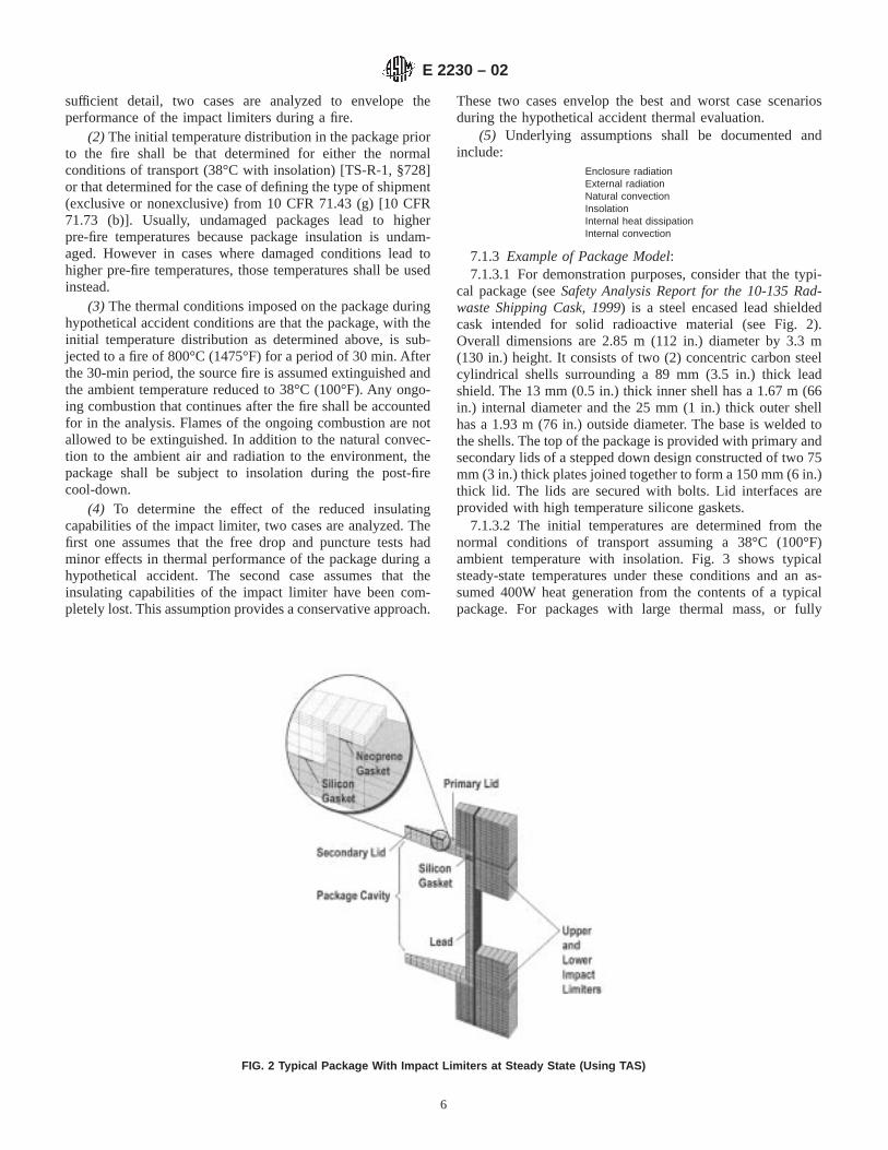
7.1.3 Example of Package Model:7.1.3.1 For demonstration purposes, consider that the typi-
cal package (seeSafety Analysis Report for the 10-135 Rad-waste Shipping Cask, 1999) is a steel encased lead shieldedcask intended for solid radioactive material (see Fig. 2).Overall dimensions are 2.85 m (112 in.) diameter by 3.3 m(130 in.) height. It consists of two (2) concentric carbon steelcylindrical shells surrounding a 89 mm (3.5 in.) thick leadshield. The 13 mm (0.5 in.) thick inner shell has a 1.67 m (66in.) internal diameter and the 25 mm (1 in.) thick outer shellhas a 1.93 m (76 in.) outside diameter. The base is welded tothe shells. The top of the package is provided with primary andsecondary lids of a stepped down design constructed of two 75mm (3 in.) thick plates joined together to form a 150 mm (6 in.)thick lid. The lids are secured with bolts. Lid interfaces areprovided with high temperature silicone gaskets.
7.1.3.2 The initial temperatures are determined from thenormal conditions of transport assuming a 38°C (100°F)ambient temperature with insolation. Fig. 3 shows typicalsteady-state temperatures under these conditions and an as-sumed 400W heat generation from the contents of a typicalpackage. For packages with large thermal mass, or fully
FIG. 2 Typical Package With Impact Limiters at Steady State (Using TAS)
E 2230 – 02
6

enclosed by a thick insulating medium, such as polyurethanefoam, a 24 h average insolation value is often used todetermine temperatures of interior components.
7.1.3.3 Two impact limiters are located at the top andbottom of the package. The impact limiters are 10-gagestainless steel shells filled with rigid polyurethane. The innersurfaces of the body and the lid are clad with 12-gage stainlesssteel. The exposed portion of the cask body is provided with a10-gage stainless steel thermal shield. A 6.4 mm (0.25 in.) gapbetween the cask body and the thermal shield is maintained byspacers. One issue that may arise during thermal qualification
is the manufacturer’s ability to maintain uniform gap width andpotential effect of gap variation on the thermal results. Theeffect of gap widths in the as-manufactured package shall beconsidered and discussed by the analyst.
7.1.3.4 Fig. 4 shows the predicted temperatures of a typicalpackage after 30 min following the initiation of the flameenvironment for the cask with the impact limiter attached. Themodel was created using TAS of Harvard Thermal.
7.1.3.5 After 30 min, the ambient temperature is reducedfrom 800°C (1475°F) to 38°C (100°F) and, consequently, thepackage begins to lose heat to the environment by natural
NOTE—Temperatures are in °F. Note that in the original figure, colors were used to represent temperature variations.FIG. 3 Initial Temperatures for Transient Analysis for a Typical Package With Impact Limiters (Using TAS)
NOTE—Temperatures are in °F. Note that in the original figure, colors were used to represent temperature variations.FIG. 4 Temperatures After the 30-Min. Fire on a Typical Package With Impact Limiters Attached (Using TAS)
E 2230 – 02
7
convection to the still air and radiation to the environment.However, the temperature in some regions of the packagecontinues to increase for some time due to heat conductionfrom surrounding regions of higher temperatures. These localtemperatures will continue to increase until the content tem-perature exceeds the temperature of the surrounding packagecomponents. The rate at which the package cools will bereduced as insolation is applied during the cool-down time. If,as permitted in the U. S. (10 CFR 71.73(b)), pre-fire conditionsare determined without the insolation specified in 10 CFR71.71, then initial package surface and contents temperatureswill often be lower than the steady state temperatures reachedwith insolation after the fire. If package temperatures withoutinsolation are lower at the start of the fire, initial fire heat fluxesto the package surface will be higher, compensating, at leastpartially, for the lack of pre-fire insolation. For packages to bequalified under both U. S. and international regulations, thiseffect shall be addressed and quantified for the regulator.
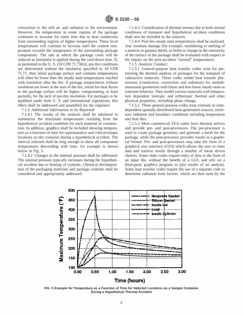
7.1.4 Additional Information to be Reported:7.1.4.1 The results of the analysis shall be tabulated to
summarize the maximum temperatures resulting from thehypothetical accident condition for each material of construc-tion. In addition, graph(s) shall be included showing tempera-ture as a function of time for representative and critical/uniquelocations on the container during a hypothetical accident. Theinterval selected shall be long enough to show all componenttemperatures descending with time. An example is shownbelow in Fig. 5.
7.1.4.2 Changes in the internal pressure shall be addressed.The internal pressure typically increases during the hypotheti-cal accident due to heating of contents. Chemical decomposi-tion of the packaging materials and package contents shall beconsidered and appropriately addressed.
7.1.4.3 Consideration of thermal stresses due to both normalconditions of transport and hypothetical accident conditionsshall also be included in the analysis.
7.1.4.4 Post-fire steady state temperatures shall be analyzed.Any resultant damage (for example, smoldering or melting ofa neutron or gamma shield, or both) or change in the emissivityof the surface of the package shall be evaluated with respect tothe impact on the post-accident “normal” temperatures.
7.1.5 Analysis Conduct:7.1.5.1 General-purpose heat transfer codes exist for per-
forming the thermal analysis of packages for the transport ofradioactive materials. These codes model heat transfer phe-nomena (conduction, convection and radiation) for multidi-mensional geometries with linear and non-linear steady-state ortransient behavior. They model various materials with tempera-ture dependent isotropic and orthotropic thermal and otherphysical properties, including phase change.
7.1.5.2 These general-purpose codes treat constant or time-dependent spatially-distributed heat-generation sources, enclo-sure radiation and boundary conditions including temperatureand heat flux.
7.1.5.3 Most commercial FEA codes have thermal solversand provide pre- and post-processors. The pre-processor isused to create package geometry and generate a mesh for thepackage, while the post-processor provides results in a graphi-cal format. Pre- and post-processors may take the form of agraphical user interface (GUI) which allows the user to enterdata and retrieve results through a number of menu drivenchoices. Some older codes require entry of data in the form ofan input file, without the benefit of a GUI, and rely on athird-party graphics program to plot results of an analysis.Some heat transfer codes require the use of a separate code todetermine radiation form factors, which are then used by the
FIG. 5 Example for Temperature as a Function of Time for Selected Locations on a Sample ContainerDuring a Hypothetical Thermal Accident
E 2230 – 02
8
thermal code to treat enclosure radiation. The results of thethermal analysis are often used by the structural analyst toperform thermal or pressure-induced stress analyses.
7.1.5.4 Thermal codes shall be qualified for package evalu-ation by verification, benchmarking, or validation. A code isverified by comparison of the results with the results ofappropriate closed form solutions.
7.1.5.5 Sample Problem Manual for Benchmarking of CaskAnalysis Codes(Glass, et al, 1988) describes a series ofproblems, which have been defined to evaluate structural andthermal codes. These problems were developed to simulate thehypothetical accident conditions given in the regulations whileretaining simple geometries. The intent of the manual is toprovide code users with a set of structural and thermalproblems and solutions which are used to evaluate individualcodes.
7.1.5.6 A code is benchmarked by comparison of the resultswith the results of other qualified codes. An alternative codevalidation method is to compare the code results to results frompackage design-based test data or hand calculations performedunder qualified QA programs.
7.1.5.7 Any code selected to perform the thermal designanalysis of a radioactive material transportation package shallbe subject to the QA program requirements for nuclearfacilities as prescribed in ASME NQA-1 or software require-ments of ISO 9000 as required by the certifying authority.
7.1.5.8 Several thermal analysis codes are available tolicensees of radioactive packages to perform the qualificationanalyses. This document is not intended to describe the variousthermal codes in detail, but a few are mentioned and brieflydescribed in Appendix X4 for the reader’s benefit. Codes notmentioned in Appendix X4 are often equally adequate toperform thermal qualification of packages to regulatory re-quirements. No comparison or evaluation of codes is providedin this document.
7.2 Pool Fire Testing7.2.1 Benefits, Limitations:7.2.1.1 Pool fire testing has been the traditional testing
method by which a package is qualified to the thermal accidentenvironment set forth in the regulations. In the test, theprototype package is placed 1 m over a pool of fuel whoselateral dimensions relative to the package meet the require-ments stated in the regulation. When atmospheric conditionsare quiescent, the fuel is ignited and the package is engulfed inthe fire plume. After 30 min, the fuel is consumed, the fire goesout, and the prototype package is left to cool down naturally.
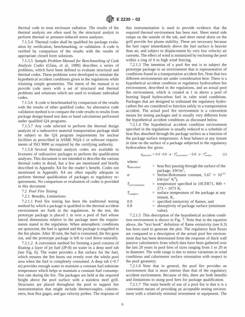
7.2.1.2 A convenient method for forming a pool consists offloating a layer of jet fuel (JP-8) on water in a deep steel tub(see Fig. 6). The water provides a flat surface for the fuel,which ensures the fire burns out evenly over the whole poolarea when the fuel is completely consumed. A deep tub (~0.7m) provides enough water to maintain a constant fuel substratetemperature which helps to maintain a constant fuel consump-tion rate during the fire. The packages are held at the requiredheight above the pool surface with a stainless steel grill.Structures are placed throughout the pool to support fireinstrumentation that might include thermocouples, calorim-eters, heat flux gages, and gas velocity probes. The response of
this instrumentation is used to provide evidence that therequired thermal environment has been met. Sheet metal sideramps on the outside of the tub, and sheet metal skirts on thegrill provide fire plume stability. These are necessary becausethe fuel vapor immediately above the fuel surface is heavierthan air, and subject to displacement by very low velocity aircurrents. The effect of wind is minimized by enclosing the poolwithin a ring of 6 m high wind fencing.
7.2.1.3 The intention of a pool fire test is to subject theprototype package to an environment that is representative ofconditions found in a transportation accident fire. Note that twodifferent environments are under consideration here. There is ahypothetical accident condition or regulatory hydrocarbon fireenvironment, described in the regulations, and an actual poolfire environment, which is created at 1 m above a pool ofburning liquid hydrocarbon fuel in calm wind conditions.Packages that are designed to withstand the regulatory hydro-carbon fire are considered to function safely in a transportationaccident. The actual pool fire environment is a convenientmeans for testing packages and is usually very different fromthe hypothetical accident conditions as discussed below.
7.2.1.4 The hypothetical accident condition environmentspecified in the regulations is usually reduced to a schedule ofheat flux absorbed through the package surface as a function ofthe package surface temperature. A heat balance at any instantin time on the surface of a package subjected to the regulatoryhydrocarbon fire gives:
qabsorbed5 0.9 · 0.8 ·s · Tenvironment4 2 0.8 ·s · Tsurface
4 (1)
where:qabsorbed = heat flux passing through the surface of the
package, kW/m2,s = Stefan-Boltzmann constant, 5.673 10-11
kW/(m2 K4),Tenvironment = temperature specified in 10CFR71, 800 +
273 = 1073 K,Tsurface = surface temperature of the package at any
instant, K,0.9 = specified emissivity of flames, and0.8 = absorptivity of package surface (minimum
value).7.2.1.5 This description of the hypothetical accident condi-
tion environment is shown in Fig. 7. Note that in the equationabove, the “text book” definition of flame emissivity (see 6.3)has been used to generate the plot. The regulatory heat fluxesare compared to a description of the actual pool fire environ-ment that has been determined from the response of thick wallpassive calorimeters from which data have been gathered overthe last 20 years in pool fires of sizes ranging from 1 to 20 min diameter. The wide range is due to minor variations in windconditions and calorimeter surface orientation with respect tothe pool geometry.
7.2.1.6 Note that in general, the pool fire provides anenvironment that is more intense than that of the regulatoryaccident environment. Because of this, there are both benefitsand limitations to using pool fires for package qualification.
7.2.1.7 The main benefit of use of a pool fire is that it is aconvenient means of providing an acceptable testing environ-ment with a relatively minimal investment in equipment. The
E 2230 – 02
9
basic set up requires some source of fuel such as a rentedtanker truck, a large open flat area, and some disposable metalsupport structures. In terms of flexibility and cost, there areobvious benefits over those associated with an oven or radiantheat facility.
7.2.1.8 A second benefit is that the pool fire environmentoften surpasses the requirements, providing a conservative test.Fig. 7 shows that the flux from a pool fire to an engulfed objectoften exceeds the criteria by a factor approaching four. Fur-thermore, the fact that the environment is a real fire shall not beoverlooked. The so-called second order characteristics, such asfire plume chemistry or non-uniform spatial and temporal heatfluxes, affect package performance in unforeseen ways; andsubjecting a prototype package to a pool fire brings outdeficiencies due to features that weren’t considered in thedesign. Examples of this that have occurred in the past withpackages in pool fires include unexpected seal response due touneven heating, and unexpected material response (out-gassing, phase change, and decomposition) due to temperatureswell above the 800°C (1475°F) design criteria.
7.2.1.9 The main limitation is that the test represents a highprogrammatic risk because the test is destructive and only
marginally under control. Once the test is initiated, there is nostopping and no readjustments are possible. One waits until thefire is over and then reconciles the available physical evidenceto show that the fire environment met or surpassed theminimum requirements as set forth in the regulations. Thereare four possible outcomes of this post-test harmonizingactivity as shown in Table 1.
7.2.1.10 The inconclusive results from the High-Fail com-bination in Table 1 are due to the pool fire environment beingoverly conservative. The inconclusive results for the Low-Passcombination are due the possibility of the fire environment notmeeting the criteria. In either case, the test has to be re-done,which requires repeating the entire package testing sequenceleading up to the fire as well.
7.2.2 Test Preparation:7.2.2.1 Except for the basic 1 m height, every pool fire test
setup is different. However, the basic simplicity of the hard-ware allows a great deal of flexibility. A pool, some supportstructure, and a supply of fuel are the basic items needed. Thebasic features of a pool fire test setup along with someadditional comments are listed in Table 2.
NOTE—Some features are to meet geometrical requirements, some stabilize the plume, and others provide evidence of supplying the requiredenvironment.
FIG. 6 A Pool Fire Test and Setup That Meets the Regulatory Requirements
E 2230 – 02
10

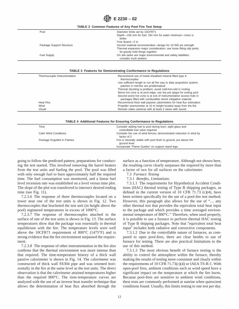
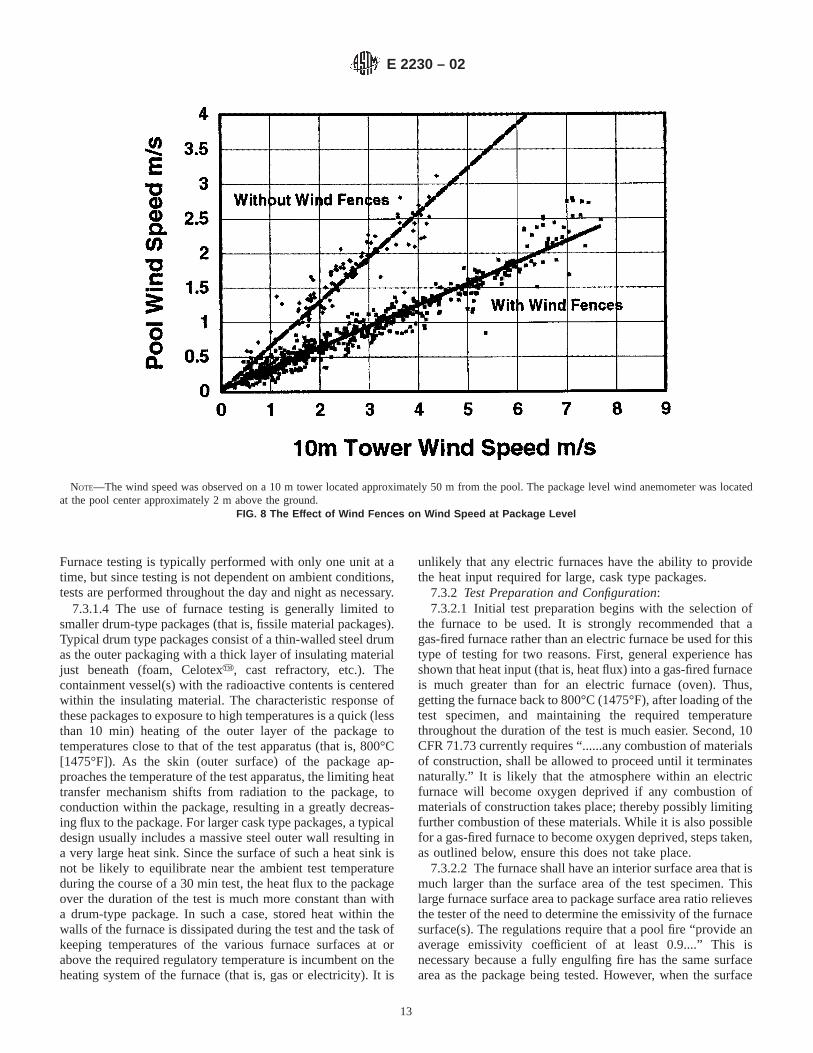
7.2.2.2 Features that aid in ensuring conformance to theregulations are shown in Tables 3 and 4. Of particular note inthe table is the use of wind fences to mitigate the effect of wind.Several testing organizations have successfully used this ap-proach, however, no written documentation has been found onthe design. The effect of placing a 30 m diameter ring of windfences around a pool setup is shown in Fig. 8. The wind fenceswere constructed of 6 m high chain link fencing fitted withaluminum slats that provided 50 % blockage.
7.2.2.3 A fire is neutrally stable with the pool flush to theground. The fuel vapor just above the burning fuel surface isheavier than air and has little upward momentum, and thus, issubject to lateral dislocation from minor air currents. Puttingthe pool surface above ground level mitigates this situation.Also, the placement of lateral dams or “flame guides” on thesupport stand just under the package helps to contain the vaporabove the pool.
7.2.3 Test Performance:7.2.3.1 The major consideration in performing the test is the
effect of wind on the results. Wind, even at low speed exercisesa major change in the fire environment in the lower regions ofa pool fire where the test article is located. The concept of aleaning fire plume as a result of wind does not apply at 1 mabove the pool surface. Instead, the fuel vapor directly abovethe fuel surface is pushed in the down wind direction causingthe fire plume to relocate out from under the package. Thisphenomena occurs at very low wind speeds, therefore it is
absolutely essential that the wind behavior at the test site bepredictable and well understood.
7.2.3.2 An example of predictable wind behavior is shownin Fig. 9. This data (wind speed and direction) was taken at atest site located in the floor of a mountain canyon over a 5 dayperiod. In that location, cold air drains down canyon during thenight hours and heated air rises up canyon during daylighthours. The change in local direction occurs twice daily (onceafter sunup and once after sundown) accompanied by a lull inwind speed. Wide area weather patterns disrupt this behaviorwhich is the cause of deviations in the Fig. 9. Note that the besttime for finding low wind conditions at this site is during theearly morning hours.
7.2.3.3 Once the time window is selected the concernbecomes choosing the appropriate time. The wind speed anddirection on a particular single day is shown in Fig. 10. Thechallenge is to set up the test between first light and the timethe wind changes direction and perform the burn before thespeed begins to rise. Accomplishing this requires a wellthought out procedure and practice. For this reason, a full dressrehearsal (including lighting the fire) is highly recommended.
7.2.3.4 An example of a completed procedure where twoshipping containers were subjected to a pool fire test under10CFR71 regulations is provided in Appendix X2. The activi-ties began several days before the actual fire, because the testunits were pre-conditioned to a desired initial temperature.This was accomplished by heating the test units in place overthe pool with barrel heaters.
7.2.3.5 Through reading the procedure provided as an ex-ample in Appendix X1, note that test materials were gathered,equipment checked out, and the pre-conditioning begun. Onthe day before the test, a general announcement of the intentionto test was made to interested parties. On the day of the test, thetest personnel were brought in at first light and wind conditionsbegan to be monitored. When it was apparent that the wind was
FIG. 7 Comparison of the Hypothetical Accident Fire Environment and the Actual Pool Fire Environment
TABLE 1 Four Possible Outcomes of a Pool Fire Test
Package Responseto Fire
Fire Environmentwith Respect to 10CFR 71
Low Heat Flux High Heat Flux
Pass Inconclusive ConclusiveFail Conclusive Inconclusive
E 2230 – 02
11
going to follow the predicted pattern, preparations for conduct-ing the test started. This involved removing the barrel heatersfrom the test units and fueling the pool. The pool was filledwith only enough fuel to burn approximately half the requiredtime. The fuel consumption was monitored, and a linear fuellevel recession rate was established on a level versus time plot.The slope of the plot was transferred to intersect desired endingtime (see Fig. 11).
7.2.3.6 The response of three thermocouples located on atower near one of the test units is shown in Fig. 12. Twothermocouples that bracketed the test unit (in height above thepool) registered temperatures in excess of 1000°C.
7.2.3.7 The response of thermocouples attached to thesurface of one of the test units is shown in Fig. 13. The surfacetemperatures show that the package was essentially in thermalequilibrium with the fire. The temperature levels were wellabove the 10CFR71 requirement of 800°C (1475°F) and isstrong evidence that the fire environment surpassed the require-ment.
7.2.3.8 The response of other instrumentation in the fire alsoconfirms that the thermal environment was more intense thanthat required. The time-temperature history of a thick wallpassive calorimeter is shown in Fig. 14. The calorimeter wasconstructed of thick wall SS304 pipe and was oriented hori-zontally in the fire at the same level as the test units. The directobservation is that the calorimeter attained temperatures higherthan the required 800°C. The time-temperature curves areanalyzed with the use of an inverse heat transfer technique thatallows the determination of heat flux absorbed through the
surface as a function of temperature. Although not shown here,the resulting curve clearly surpasses the required by more thana factor of two for all surfaces on the calorimeter.
7.3 Furnace Testing7.3.1 Benefits, Limitations:7.3.1.1 The requirements for Hypothetical Accident Condi-
tions (HAC) thermal testing of Type B shipping packages, asdefined in the current version of 10 CFR 71.73 (c)(4), havebeen written specifically for the use of a pool-fire test method.However, this paragraph also allows for the use of “.... anyother thermal test that provides the equivalent total heat inputto the package and which provides a time averaged environ-mental temperature of 800°C.” Therefore, when used properly,it is possible to use a furnace to perform thermal HAC testingof Type B shipping packages. Note that9equivalent total heatinput9 includes both radiative and convective components.
7.3.1.2 Due to the controllable nature of furnaces, as com-pared to open pool-fires, there are clear benfits to use offurnace for testing. There are also practical limitations to theuse of this method.
7.3.1.3 The most obvious benefit of furnace testing is theability to control the atmosphere within the furnace, therebymaking the results of testing more consistent and clearly withinthe requirements of 10 CFR 71.73(c)(4) or IAEA TS-R-1. Withopen-pool fires, ambient conditions such as wind speed have asignificant impact on the temperature at which the fire burns.Because pool-fires are sensitive to ambient wind conditions,thest tests are commonly performed at sunrise when quiescientconditions found. Usually, this limits testing to one test per day.
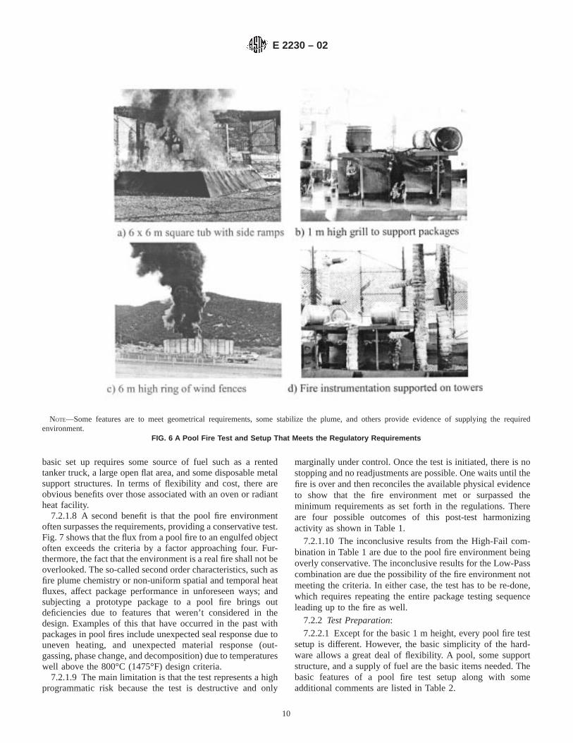
TABLE 2 Common Features of Any Pool Fire Test Setup
Pool Diameter limits set by 10CFR71Depth—150 mm for fuel; 150 mm for water minimum—more is
betterFree Board—2 in.
Package Support Structure Inconel material recommended—design for 10 000 psi strengthThermal expansion major consideration; use loose fitting slip joints;
let gravity hold things togetherFuel Supply On site tanks are major environmental and safety liabilities;
consider truck tankers
TABLE 3 Features for Demonstrating Conformance to Regulations
Thermocouple Instrumentation Recommend use of metal sheathed mineral filled type Kthermocouples
Use sufficient length to run all the way to data acquisition system;patches in mid-fire are problematical
Thermal shunting is problem; avoid cold-hot-cold in routingWorst hot zone is at pool edge; use tea pot spigot for exiting poolSecond worst hot zone is at exit of instrumentation access hole in
packages filled with combustible shock mitigation materialHeat Flux Recommend thick wall passive calorimeters for heat flux estimationWind Propeller anemometer at 10 m height located away from the fireVisual Remote video cameras with at least 2 views with sound
TABLE 4 Additional Features for Ensuring Conformance to Regulations
Time Consider adding fuel to pool during burn; sight glass andcontrollable fuel valve required
Calm Wind Conditions Consider the use of wind fences; demonstrated reduction in wind byfactor of 2
Package Engulfed in Flames Fire is neutrally stable with pool flush to ground, put above theground level
Incorporate “Flame Guides” on support stand legs
E 2230 – 02
12
Furnace testing is typically performed with only one unit at atime, but since testing is not dependent on ambient conditions,tests are performed throughout the day and night as necessary.
7.3.1.4 The use of furnace testing is generally limited tosmaller drum-type packages (that is, fissile material packages).Typical drum type packages consist of a thin-walled steel drumas the outer packaging with a thick layer of insulating materialjust beneath (foam, Celotexy, cast refractory, etc.). Thecontainment vessel(s) with the radioactive contents is centeredwithin the insulating material. The characteristic response ofthese packages to exposure to high temperatures is a quick (lessthan 10 min) heating of the outer layer of the package totemperatures close to that of the test apparatus (that is, 800°C[1475°F]). As the skin (outer surface) of the package ap-proaches the temperature of the test apparatus, the limiting heattransfer mechanism shifts from radiation to the package, toconduction within the package, resulting in a greatly decreas-ing flux to the package. For larger cask type packages, a typicaldesign usually includes a massive steel outer wall resulting ina very large heat sink. Since the surface of such a heat sink isnot be likely to equilibrate near the ambient test temperatureduring the course of a 30 min test, the heat flux to the packageover the duration of the test is much more constant than witha drum-type package. In such a case, stored heat within thewalls of the furnace is dissipated during the test and the task ofkeeping temperatures of the various furnace surfaces at orabove the required regulatory temperature is incumbent on theheating system of the furnace (that is, gas or electricity). It is
unlikely that any electric furnaces have the ability to providethe heat input required for large, cask type packages.
7.3.2 Test Preparation and Configuration:7.3.2.1 Initial test preparation begins with the selection of
the furnace to be used. It is strongly recommended that agas-fired furnace rather than an electric furnace be used for thistype of testing for two reasons. First, general experience hasshown that heat input (that is, heat flux) into a gas-fired furnaceis much greater than for an electric furnace (oven). Thus,getting the furnace back to 800°C (1475°F), after loading of thetest specimen, and maintaining the required temperaturethroughout the duration of the test is much easier. Second, 10CFR 71.73 currently requires “......any combustion of materialsof construction, shall be allowed to proceed until it terminatesnaturally.” It is likely that the atmosphere within an electricfurnace will become oxygen deprived if any combustion ofmaterials of construction takes place; thereby possibly limitingfurther combustion of these materials. While it is also possiblefor a gas-fired furnace to become oxygen deprived, steps taken,as outlined below, ensure this does not take place.
7.3.2.2 The furnace shall have an interior surface area that ismuch larger than the surface area of the test specimen. Thislarge furnace surface area to package surface area ratio relievesthe tester of the need to determine the emissivity of the furnacesurface(s). The regulations require that a pool fire “provide anaverage emissivity coefficient of at least 0.9....” This isnecessary because a fully engulfing fire has the same surfacearea as the package being tested. However, when the surface
NOTE—The wind speed was observed on a 10 m tower located approximately 50 m from the pool. The package level wind anemometer was locatedat the pool center approximately 2 m above the ground.
FIG. 8 The Effect of Wind Fences on Wind Speed at Package Level
E 2230 – 02
13

area of the furnace is much greater than the surface area of thepackage, the emissivity of the furnace surface has no effect onthe rate of heat transfer to the package, rather the rate of heattransfer to the package is controlled by the absorptivity of the
package (for radiative heat transfer). A furnace surface area ofat least 10 times that of the package is recommended.
7.3.2.3 The furnace used for package testing shall have adigital control system for regulation of the temperature within
FIG. 9 Example of 5 Consecutive Days of Wind Speed and Direction at a Pool Fire Test Site
FIG. 10 Set Up Activities Start at First Light; the Fire is Ignited When the Wind Shifts in Direction
E 2230 – 02
14

the furnace. Typical control systems include two thermo-couples, one for the main control and one as a high-temperature limit in case the main control unit fails (usuallydue to thermocouple malfunction). These control thermo-couples are typically mounted to monitor atmospheric tempera-tures within the furnace, while the temperatures of greatestinterest to package testers are those of the furnace surfaceswhich are radiating to the package. It is also possible for flamesfrom a package being tested to impinge directly on the controlthermocouple resulting in high temperature readings and pos-sible loss of power to the furnace. For these reasons, it isnecessary to use a furnace in which the control and upper limitfurnace temperatures are easily adjusted. It is also recom-mended that a furnace with a maximum operating temperatureof at least 1000°C (1832°F) be selected (1100°C [2012°F]preferred).
7.3.2.4 Loading of the test specimen, and to a lesser extent,unloading is key to a successful completion of the tests. Afurnace is typically heat soaked prior to loading of the testspecimen. During loading, a significant decrease of the tem-peratures (both atmospheric and surfaces) within the furnaceoften takes place. Thus, loading the specimen both quickly andsafely is important. For most furnaces a loading time of up to90 s is acceptable; however, this is dependent on the individualfurnace and it is recommended that mock trials be used prior toloading to determine the effects of loading on furnace tempera-tures. Loading is achieved either by an automatic loadingmachine that is specifically outfitted for the furnace being used
or through the use of a forklift. Clearly the machine that hasbeen outfitted for the specific purpose of loading the furnace ispreferable as repeatability is assured. Loading with a forkliftrequires great skill on the part of the operator.
7.3.2.5 The package shall be loaded onto a stand inside thefurnace. It shall not be loaded directly onto the floor of thefurnace. If the package is set on the floor, the area directlybelow the package will most assuredly drop below the regula-tory temperature of 800°C (1475°F). Thus, the package is not“fully engulfed” as is required by regulations. The stand shallbe designed in a manner such that contact between the standand the package is minimized, and the obstruction of the viewof the furnace surfaces from the package shall also beminimized. When using a loading machine to load the furnace,the stand is usually a permanent part of the furnace test set-up.For forklift loading, the stand is placed in the furnace prior tothe test (this is required). The package is then loaded onto thestand to initiate the test, and when the test is complete both thepackage and stand are removed as single piece. Removing ahot package from a stand is very difficult with a forklift andremoving both the stand and the package is considerably easierand safer (the stand is designed for ease of forklift use; thepackage will not be designed to specifically facilitate removalof the package from the stand).
7.3.2.6 The regulations require “an average flame tempera-ture of at least 800°C (1475°F) for a period of 30 min or anyother thermal test that provides the equivalent total heat input
FIG. 11 Control of burn time is accomplished by adding fuel to pool during the fire. The fuel consumption rate is established duringthe first half of the fire, the slope is transferred to intercept the desired ending time and fuel is added until the level reaches the new
line.
E 2230 – 02
15

to the package and which provides a time averaged environ-mental temperature of 800°C.” To ensure that the time aver-aged environment is at least 800°C, it is necessary to monitorthe temperatures of the surfaces that are radiating to thepackage, namely the walls, floor and ceiling of the furnace(assuming a rectangular furnace). The simple use of the controlthermocouple as evidence of the time averaged temperatureenvironment is not sufficient for several reasons. For one,combustion gases from the package’s materials of constructionimpinges on the control thermocouple indicating a hot furnacewhen in fact the wall temperatures are actually decreasing,sometimes significantly. Also, some furnaces have relativelyuneven heating from side to side or from front to back therebyrendering the reading of a single thermocouple useless. Finally,since most of the heat transfer to the package is through radianttransfer, it is paramount that the radiative environment withinthe furnace be documented.
7.3.2.7 Mounting of thermocouples within a furnace hasbeen successfully achieved in two different manners in thepast. If the owner of the furnace is amenable to structuralmodifications, the simplest method is to mount the thermo-couple through the wall of the furnace by first drilling holes inthe furnace and then pushing the thermocouples through theholes. A less invasive but also less dependable technique is torun the thermocouple leads along the walls of the furnace suchthat the thermocouple junctions are mounted in the respectivelocations. If this method is used, then typically all the leadscome together at the bottom of the furnace and out the door. Ifan electric furnace is used, it is important to ensure that the
thermocouple leads do not come in contact with the heatingelements, especially if the latter method of installation is used.As the furnace heats-up, the thermocouple sheaths will grow inlength. In an electric furnace, this allows the sheaths to comein contact with the heating elements resulting in shorted-outthermocouples.
7.3.2.8 Thermocouples shall be mounted in the walls of thefurnace in such a manner to measure the temperature of thewall (not the temperature of the atmosphere near the wall). Thisrequires that the junction of the thermocouple be mounted flushwith the surface of the furnace. When bringing thermocouplesthrough the wall of the furnace, the hole shall first be drilled allthe way through the wall. Mounts are then attached to theoutside of the furnace and the thermocouples are broughtthrough the mounts until the end of the junction is just flushwith the furnace surface. For thermocouples that are strungalong the furnace surfaces, a small area of the refractory isscratched away creating an indentation for the thermocouplejunction. For use of either method of mounting, the thermo-couple tip shall then be covered with a very light covering ofa refractory patch material. This ensures that the emissivity ofthe radiative surface at which the temperature is being mea-sured is similar to that of the furnace wall and it also assuresthat a surface (or slightly sub-surface) temperature rather thanan atmospheric temperature is being measured.
7.3.2.9 A minimum of three thermocouples shall be placedon each distinct radiative surface within a furnace. Assuming abox type furnace, this totals to 18 surface thermocouples (3 oneach of 4 walls, the floor and the ceiling). The thermocouple
NOTE—The test item was 1 m above the pool.FIG. 12 Temperature Time Histories of Thermocouples in the Fire Near a Test Item
E 2230 – 02
16

placement shall ensure that all zones of the radiating surfaceare measured. By assuming that the surface area of the furnaceis much larger than the surface area of the package, in effectone is assuming that all furnace radiating surfaces are supply-
ing heat. Thus, all areas of these surfaces need to be monitored.An easy way to accomplish this is to mount the three
FIG. 13 Temperature of Package Surface in 4 Locations During the Fire
FIG. 14 Response of a Thick Wall Stainless Steel Calorimeter
E 2230 – 02
17

thermocouples on a single surface in a diagonal line. Specifi-cally, mounting the thermocouples in a horizontal or verticalline shall be avoided.
7.3.2.10 Additional items within the furnace for testingpurposes, specifically test stands, shall be thermocoupled. Thestand shall be at temperature at the beginning and throughoutthe duration of the test, thus demonstrating that the stand is notacting as a protective heat sink for the package.
7.3.2.11 A computerized data acquisition system to gatherand record data is recommended but not required. All portionsof the data acquisition system shall be calibrated and certifiedas discussed in Appendix X5 of this document. Prior to testing,the furnace temperatures shall be recorded during the heat-soakprocess as well as between consecutive test runs. During thesetimes, collecting (recording) data at 15 min intervals isrecommended. During testing, temperatures shall be recordedat least every minute with 15 or 30 s intervals suggested.
7.3.2.12 As 10CFR71 requires “......any combustion of ma-terials of construction, shall be allowed to proceed until itterminates naturally,” it is necessary to ensure that the oxygenlevel within the furnace remains at or above the level that isfound at the center of a pool fire test. This is accomplished ina gas-fired furnace by de-tuning the burners such that excess airis forced into the furnace during testing. Monitoring of theoxygen level in the flue gases leaving the furnace during testingis then used to document the availability of O2 for materials ofconstruction combustion during testing. Monitoring of O2
levels within an electric furnace is more complicated as fluegases generally do not exist. In such a situation, some othertechnique shall be employed to ensure the oxygen level doesnot drop too low and is documented. Additionally, somepackages are constructed of materials which will not combustat the temperatures associated with this type of testing. Whenit is shown that no materials of construction are combustible,then there is no need to monitor oxygen levels within the testapparatus.
7.3.2.13 To meet the requirements of 10 CFR 71, the testspecimen shall be at the shaded normal conditions of transport(NCT) temperature prior to the initiation of the thermal test.
7.3.2.14 The package to be tested shall be instrumentedsuch that the surface temperatures of the package is monitored.A typical mounting approach is described in Appendix X5.Note that the junction of the thermocouple shall not have directa “radiative view” of the furnace heat source. Such a viewskews temperature measurements. The ends of the thermo-couple are typically covered with a foil piece as described inAppendix X5.
7.3.2.15 Prior to inserting the package into the furnace, thefunctionality of all of the thermocouples (both those measuringfurnace temperatures and package temperatures) shall bechecked. Once it is determined that all thermocouples areworking, the package is readied for insertion (for example,picking the package up with a forklift or loading the packageonto a loading machine, usually with an overhead crane). Theorientation of the package is important, especially if there issignificant damage to the package from previous structural
testing. While this standard does not deal with packageorientation, one shall be able to defend the orientation used as“worst-case.”
7.3.3 Additional Data to be Reported—The following datashall be recorded during testing:
7.3.3.1 All thermocouple data (typically in 15 or 30 sintervals for the duration of the test),
7.3.3.2 Time at which the package is inserted into thefurnace,
7.3.3.3 Time at which the test begins,7.3.3.4 Time at which the package is removed from the
furnace, and7.3.3.5 Test apparatus gas oxygenation (every 5 min during
the test when combustible materials of construction arepresent).
7.3.4 Test Conduct:7.3.4.1 The actual testing of the package is simple and
straightforward. The furnace door is opened and the package isloaded into the furnace. When the test is complete, the packageis removed from the furnace. However, the determination ofwhen the test begins, and thereby when it ends (that is, 30 minlater) is less straightforward.
7.3.4.2 The regulations require a “....thermal test that pro-vides the equivalent total heat input to the package (of an800°C [1475°F] pool fire with an emissivity coefficient of 0.9)and which provides a time averaged environmental tempera-ture of 800°C.” There are several ways to get to this point eachof which, if properly documented, is acceptable.
7.3.4.3 The method which requires the least calculationalinput is often referred to as the “steady-state” method (seeCombination Test/Analysis Method…, 1992, and Shah, 1996).For this type of test, the package is inserted into the furnaceand the surface of the package is allowed to come to tempera-ture (800°C [1475°F]). The point at which all package surfacethermocouples and the average of the furnace thermocouplesread 800°C (1475°F) or greater is considered the beginning ofthe 30-min test. During the ensuing 30 min, the packagesurface temperatures as well as the average furnace tempera-ture shall remain at or above 800°C (1475°F).
7.3.4.4 Since a perfect 800°C (1475°F) pool fire never heatsa package surface above 800°C (1475°F) it is clear that this testmethod meets all of the requirements in 10 CFR 71.73(c)(4)and IAEA TS-R-1, Section VII. From the perspective of theapplicant/tester/package manufacturer, the steady state methodis an over test of the package, however from the perspective ofthe regulator, the benefit of this test method is that this methodwill adequately satisfy the regulatory requirements for thehypothetical accident conditions and provide added support tothe applicant’s assertion that the package met the requirements.For small drum-type packages, it often takes 8 to 12 min for thedrum surface to reach 800°C (1475°F), thus the package isactually inside the furnace for 38 to 42 min. Also, to heat thepackage to at or above 800°C (1475°F), it is typically neces-sary to run the furnace at 820 to 850°C (1508 to 1562°F). Somefurnaces have cold spots that require the tester to keep thataverage temperature of the furnace higher just to ensure thatportions of the package surface, which have a strong view of a
E 2230 – 02
18

cold spot, remain at or above 800°C (1475°F). Clearly, thesteady-state method cannot be used on large heat-sink pack-ages.
7.3.4.5 Some additional guidance has been provided by theUnited States Department of Energy for thermal testing ofpackages in the form of Combination Test/Analysis MethodUsed to Demonstrate Compliance to DOE Type B PackagingThermal Test Requirements, SG 140.1. The document is oflimited use since the publication date of 1992 predates theinclusion of convection as a necessary component in thethermal test defined in 10 CFR 71. This document providesinformation for use in a non-steady-state method; however, aspecific furnace temperature above 800°C is used for theduration of the test simply based on the instantaneous heat fluxat the beginning of the test. The information is inconsistentwith the current version of 10 CFR 71.73 as the time-averagedenvironmental temperature is now specified. The methodspresented are acceptable, though stringent, test methods.
7.3.4.6 To perform a furnace test without utilizing thesteady-state method, some knowledge or analysis of thepackage’s response to a pool-fire test is needed. If the total heatinput (that is, the integration of the heat flux from thebeginning of the test to the end) a package receives if exposedto a perfect 800°C fully engulfing pool-fire including the heattransfer from radiation and convection is determined, then itcan be shown that the package subjected to a furnace testreceived either a greater or lesser total heat input during theactual physical testing. For a test method to be acceptable, itmust provide an equal or greater total heat input as well as an“averaged environmental temperature of 800°C.” Some gen-eral guidelines for performing such an analysis are found inVan Sant, et al, 1993. This document also predates the currentversion of the regulations, but the insight necessary to make thediscussed calculations is included.
7.3.4.7 The method of loading and unloading the testspecimen varies from furnace to furnace. As stated earlier, if aloading machine is used, it is likely the stand will stay in thefurnace after the test, but if a forklift is used, it is usually easierto remove the test specimen and the stand as a single unit.Because the furnace is typically turned off during this time andlosing heat due to the door being open, it is necessary tocomplete the loading process as quickly as possible. Thisallows the furnace to stay hotter, and especially if the steady-state method is used, allows the 30-min test period to beginsooner. It is paramount that all loading and unloading activitiesas well as other processes associated with the test (dataacquisition, etc.) be thoroughly practiced and/or tested, asappropriate, prior to test initiation.
7.3.4.8 Once the package has been unloaded from thefurnace, it shall cool naturally. This means that the packagemust not be exposed to either significantly cold temperatures orto breezes of any sort. Ideally, the ambient temperature shall benear 38°C (100°F). Recent interpretation of the regulations hasrequired the inclusion of the effects of insolation during thecool-down period. This is typically shown, through analysis, tobe insignificant. However, the applicant often desires to simu-late the insolation according to 10 CFR 71.71.
7.3.4.9 After unloading, the temperatures of the surfaces ofthe package typically fall quickly. This data is of no real use, sothere is no need to continue monitoring these temperatures.Some test specimens are instrumented to record interiorpackage temperatures such as containment vessel tempera-tures. Typically, these values will continue to rise for sometime after the package is removed from the furnace. Suchtemperatures must continue to be monitored until well afterthey have peaked. Generally, the data are recorded at 5 to 15min intervals. This information often also proves helpful indetermining the relative non-effect of introducing insolationfollowing the thermal test.
7.3.5 Adjustment of Results for Differences from Regulatoryand Initial Boundary Conditions:
7.3.5.1 There are no specific adjustments necessary for TypeB shipping packages thermally tested in a furnace. Standardmethods for making adjustments for items such as reducedcontent weight, package temperature gradients due to decayheat of contents, etc, be made as outlined in Appendix X1 ofthis document.
7.3.6 Abnormal Events, Remediation:7.3.6.1 There are many abnormal events that take place
during furnace testing. However, remediation of such problemsis often nearly impossible. It is strongly recommended that theentire test procedure be practiced using a cold furnace well inadvance of the actual test to ensure that all procedures willwork correctly and that unexpected difficulties are discoveredprior to the actual test. It is also recommended that somepractice take place with a “dummy” test unit and an “at-temperature” furnace to ensure that expectations of the test aremet.
7.4 Radiant Heat Testing7.4.1 Benefits, Limitations:7.4.1.1 Pool fire testing (see 7.2) has been the traditional
method by which one tests a package to 10CFR71. A packageis exposed to an engulfing fire for the required duration of 30min. Other methods exist by which one generates the environ-ment specified in 10CFR71, for example furnace testingdiscussed in 7.3. The use of radiant heat lamps is anothermethod for thermal testing of packages.
7.4.1.2 Radiant heat simulations of high temperature envi-ronments has been used for many years for high temperaturetesting (that is, up to 1200°C [2200°F]). In this method,infrared lamps are the heat source and are made of a spiralwound tungsten filament enclosed in a fused quartz envelopeand powered electrically. Each lamp is about 30 cm long and10 mm in diameter (12 in. long and3⁄8 in. diameter). Typically,arrays of these lamps form lamp panels as shown in Fig. 15.The lamp panels are placed in front of a stainless steel orinconel enclosure that surrounds the package to be qualified asshown in Fig. 16. The lamps heat the steel enclosure (which isnormally painted black,e = 0.85), which heats the package.The enclosure is typically instrumented with a number ofmineral insulated, metal sheathed thermocouples to measurethe enclosure temperature. The enclosure is rapidly broughtfrom ambient to the “flame temperature,” in the case of10CFR71 the flame temperature is 800°C (1475°F). The
E 2230 – 02
19
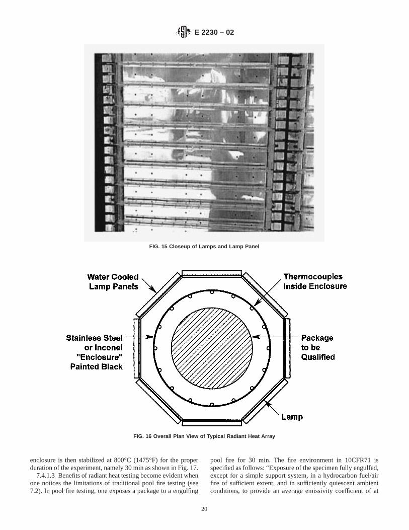
enclosure is then stabilized at 800°C (1475°F) for the properduration of the experiment, namely 30 min as shown in Fig. 17.
7.4.1.3 Benefits of radiant heat testing become evident whenone notices the limitations of traditional pool fire testing (see7.2). In pool fire testing, one exposes a package to a engulfing
pool fire for 30 min. The fire environment in 10CFR71 isspecified as follows: “Exposure of the specimen fully engulfed,except for a simple support system, in a hydrocarbon fuel/airfire of sufficient extent, and in sufficiently quiescent ambientconditions, to provide an average emissivity coefficient of at
FIG. 15 Closeup of Lamps and Lamp Panel
FIG. 16 Overall Plan View of Typical Radiant Heat Array
E 2230 – 02
20

least 0.9, with an average flame temperature of at least 800°C(1475°F) for a period of 30 min, or any other thermal test thatprovides the equivalent total heat input to the package andwhich provides a time averaged environmental temperature of800°C. The fuel source must extend horizontally at least 1 m(40 in.), but may not extend more than 3 m (10 ft), beyond anyexternal surface of the specimen, and the specimen must bepositioned 1 m (40 in.) above the surface of the fuel source. Forpurposes of calculation, the surface absorptivity coefficientmust be either that value which the package may be expectedto possess if exposed to the fire specified or 0.8, whichever isgreater; and the convective coefficient must be that value whichmay be demonstrated to exist if the package were exposed tothe fire specified. Artificial cooling may not be applied after thecessation of external neat input, and any combustion ofmaterials of construction, must be allowed to proceed until itterminates naturally.”
7.4.1.4 The radiant heat testing alternative bypasses somelimitations of traditional pool fire testing. By use of lamps anda steel enclosure painted black, one obtains a known tempera-ture heat source (measured with thermocouples), of highemissivity (black paint), that is not dependent on the windspeed or direction. Experience with Pyromarkt black paint hasbeen good. The emissivity stays high (about 0.85) even afterthe initial curing, which causes some black smoke. Measuredemissivity before and after the paint was applied has beenfound to be stable at about 0.85. If care is taken, the enclosureis made of relative uniform temperature (for example,65 %)so the temperature source is uniform at whatever temperatureis desired (for example, 800°C (1475°F)). The test length iscontrolled precisely by beginning the test when the enclosure
reaches the desired temperature and simply turning off thepower system when 30 min has elapsed as shown in Fig. 17.Lastly, if desired, the non-uniformity present in all pool fires isavoided by use of the uniform temperature enclosure.
7.4.1.5 Controlling heat flux to the top and bottom of thetest object is an important consideration in radiant heat testing.Heat lamp arrays and the steel enclosure are normally posi-tioned vertically on stands around the test object, and heatingof the top and bottom of the object is accomplished byextending the height of the lamp arrays and enclosure aboveand below the test object. The view factor from the heated steelenclosure to the top and bottom of the test object shall beconsidered in designing the test. In some cases additionalinsulated enclosure pieces may be required above or below thetest object to create a hot cavity completely surrounding thetest object.
7.4.1.6 Radiant heat testing is especially beneficial for caseswhere it is desired to obtain experimental data to compare withthermal model predictions (see 7.1). With the well controlledenvironment (as compared with pool fires), radiant heat testsprovide a uniform, constant boundary condition more suitablefor use with comparison with model predictions. Wind effectsare non-existent in radiant heat simulations. Wind plays asignificant role in the heat transfer in pool fires (see 7.2).
7.4.1.7 One key limitation of radiant heat testing is startupcost. To develop the radiant heat capability requires a highpower substation (Sandia’s Radiant Heat Facility has a dedi-cated 6 MW substation), transformers, power control system,switchgear, water cooling for the lamp arrays, banks of lamppanels, and lamps. Once up and running, the facility isrelatively inexpensive to operate and is competitive with open
FIG. 17 Typical Enclosure Temperature Profile
E 2230 – 02
21

pool fire testing. Open pool fire testing often requires addi-tional environmental approvals (for example, for the NationalEnvironmental Policy Act, NEPA), and “burn permits” if neara city with air quality restrictions. Radiant heat testing nor-mally does not require such permits because no fuel is burned.
7.4.1.8 There are several differences in the heat transfermechanisms between pool fires and radiant heat testing. Theconvective heat transfer in radiant heat tests is different than forpool fires—the latter being greater. This is usually not aproblem because the overall heat transfer in fires is thought tobe dominated by radiative heat transfer. Normally, the highestemissivity attainable on the enclosure via paint ise = 0.85, note = 0.90 as required by the regulations. An adjustment up inenclosure temperature is often required. In the many radiantheat tests performed in the past, customers have specified auniform circumferential and axial temperature on the enclo-sure. This in turn creates a uniform heating pattern on thepackage. This is very different than what actually occurs inopen pool fires (see 7.2). Significant non-symmetric circum-ferential heating of a package causes larger thermal stressesthan present in a symmetric circumferential heating environ-ment. This non-symmetric heating is often difficult to repro-duce in radiant heat testing. Because the steel enclosure mountis open to outside air at the bottom, natural convection drawsa sufficient air supply inside the steel enclosure to supportcombustion of materials inside the package.
7.4.1.9 Simulation of convection from flame velocities of 5to 10 m/s (11.2 to 27.4 mph) in radiant heat testing is difficultbut possible. One generates 800°C (1475°F) air from anexternal source and ducts it to the annular space between thesteel enclosure and the package, then provide an exit path forthe air out of the space around the heater array. Existing radiantheat facilities have not provided this kind of convectiveboundary condition in past tests. This was related to theconcept that almost all of the heat transfer in fires was due toradiative effects. What little was caused by the convection wasaccounted for by a slightly increased flame temperature (in thiscase the steel enclosure temperature was raised slightly). Bothmethods are used, but the easier method is to increase theaverage steel enclosure temperature because it requires lessequipment.
7.4.1.10 In summary, radiant heat testing generates a verysimilar radiative environment, but a less severe convectiveenvironment when compared to pool fires.
7.4.2 Test Preparation and Configuration:7.4.2.1 Test preparation and configuration are separated into
several overall tasks:ProceduresSetupCalibration and uncertainty analysis
7.4.2.2 Procedures span the following areas:(1) Environmental Documentation—If the package has a
significant flammable component that generates toxic gases orradioactive debris, or other hazardous materials, NEPA (Na-tional Environmental Policy Act) approval is often required(that is, an Environmental Assessment (EA) or EnvironmentalImpact Statement, EIS). Normally, radiant heat testing does notrequire an EA or EIS for NEPA approval for typical packagetesting (that is, without radioactive materials).
(2) Safety Procedures—Because of the lethal voltages andcurrents (480 V, 1000 A) encountered in large package radiantheat testing, safety procedures are very important to reduce thechance of injury or equipment damage.
(3) Quality Procedures—To ensure adherence to a qualityprocess, QA procedures are provided so that a regulatoryagency has the proper information to make a judgement as towhether or not an experiment was performed according to theregulations. Refer to 10 CFR71, Subpart H - Quality Assurancefor a discussion of QA requirements, procedures, etc.
(4) Operational Procedures—These are step-by-step pro-cedures written to carefully analyze the steps required toperform a radiant heat test. These often have simple instruc-tions such as “start the water pump and ensure water isflowing,” but sometimes also include safety procedures. Often,safety, quality, and operational procedures are combined into asingle list of procedures where the entire experiment isanalyzed and steps described. (See Appendix X2 for a descrip-tion of operational procedures, sometimes called “Job AnalysisWork Sheets,” or JAWS.)
7.4.2.3 Test Setup Requirements:(1) Determine Lamp Array Size Needed—For small pack-
ages, that is, less than about 1.2 m (4 ft) long, a single heightlamp array is most commonly used. For packages longer thanabout 1.2 m (4 ft) but shorter than about 7.4 m (8 ft), lamparrays made of two-high lamp panels are used. Each panel isabout 30.5 cm (12 in.) wide and 1.2 m (46 in.) long. They aremounted so the long dimension is vertical, and panels areplaced side-by-side to surround the steel enclosure as shown inFig. 2. The enclosure is stainless steel or inconel because thesematerials withstand temperatures up to about 1200°C (2200°F),which spans the maximum temperatures normally seen inhydrocarbon fuel fires. The steel enclosure is of a sufficientdiameter to provide easy installation of the package, and of thesame length as the lamp panels. The enclosure is circular andformed by bending a flat plate into a circle and welding theseam. The enclosure is painted with a high emissivity blackpaint on both sides (e = 0.85).
(2) Design Stand to Hold Package—This is relatively easybecause stands exist from past testing, especially if the packageis to be placed with the long side vertical, and becausepackages are often not heavy. However, if the package is to beplaced with the long side horizontal, the entire lamp array isoften rotated 90° from its most often used configuration, and anew stand built. Alternatively, the lamp array is kept verticalbut made a larger diameter, and a larger diameter steelenclosure made to accommodate the longer horizontal dimen-sion. Based on IAEA TS-R-1, “The package should bemounted with the shortest dimension vertical for the mostuniform flame cover, unless a different orientation will lead toa higher input or greater damage, in which case such anarrangement should be chosen.” In the case of the radiant heattest, presuming the longest dimension is not too long to fit intothe radiant heat array, the orientation chosen be the case withthe greatest expected damage.
(3) Determine Temperature Profile Required onEnclosure—This is most often a constant, uniform temperature:800°C (1475°F). As we learn more about fires (see 7.2)
E 2230 – 02
22
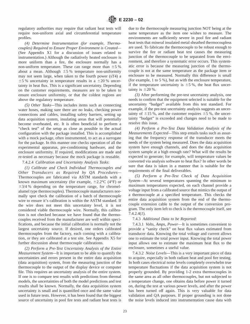
regulatory authorities may require that radiant heat tests willrequire non-uniform axial and circumferential temperatureprofiles.
(4) Determine Instrumentation (for example, Thermo-couples) Required to Ensure Proper Environment is Created—(See Appendix X1 for a discussion of issues related toinstrumentation.) Although the radiatively heated enclosure ismore uniform than a fire, the enclosure normally has anon-uniform temperature. These can range more than65 %about a mean. Although65 % temperature non-uniformitymay not seem large, when taken to the fourth power (sT4) a65 % uncertainty in temperature results in a620 % uncer-tainty in heat flux. This is a significant uncertainty. Dependingon the customer requirements, measures are to be taken toensure enclosure uniformity, or that the coldest regions areabove the regulatory temperature.
(5) Other Tasks—This includes items such as connectingwater hoses, making sure there are no leaks, checking powerconnections and cables, installing safety barriers, setting updata acquisition system, insulating areas that will potentiallybecome overheated, etc. It is often beneficial to perform a“check test” of the setup as close as possible to the actualconfiguration with the package installed. This is accomplishedwith a mock package, often instrumented, to act as a surrogatefor the package. In this manner one checks operation of all theexperimental apparatus, pre-conditioning hardware, and theenclosure uniformity. If required, modifications are made andre-tested as necessary because the mock package is reusable.
7.4.2.4 Calibration and Uncertainty Analysis Tasks:(1) Calibrate and Check Individual Thermocouples and
Other Transducers as Required by QA Procedures—Thermocouples are fabricated via ASTM standards with aknown maximum uncertainty (for example,62.2°C (4°F) or63/4 % depending on the temperature range, for chromel-alumel type thermocouples). Thermocouple manufacturers nor-mally spot check the calibration of a batch of thermocouplewire to ensure it’s calibration is within the ASTM standard. Ifthe wire does not meet this uncertainty level, it is notconsidered viable thermocouple wire. Normally, this calibra-tion is not checked because we have found that the thermo-couples received from the manufacturer are well within speci-fications, and because the initial calibration is normally not thelargest uncertainty source. If desired, one orders calibratedthermocouples from the factory, each coming with a calibra-tion, or they are calibrated at a test site. See Appendix X5 forfurther discussion about thermocouple calibrations.
(2) Perform a Pre-Test Uncertainty Analysis of the EntireMeasurement System—It is important to be able to quantify theuncertainties and errors present in the entire data acquisition(data acquisition) system, from the measuring junction of thethermocouple to the output of the display device or computerfile. This requires an uncertainty analysis of the entire system.If one is to compare test results with predictions from thermalmodels, the uncertainties of both the model predictions and testresults shall be known. Normally, the data acquisition systemuncertainty is small and is quantified once and the same valueused in future tests. However, it has been found that the biggestsource of uncertainty in pool fire tests and radiant heat tests is
due to the thermocouple measuring junction NOT being at thesame temperature as the item one wishes to measure. Theenvironments are sufficiently severe in pool fire and radiantheat tests that mineral insulated metal sheathed thermocouplessare used. To fabricate the thermocouple to be robust enough tosurvive the fire or radiant heat test causes the measuringjunction of the thermocouple to be separated from the envi-ronment, and therefore a systematic error occurs. This system-atic error is because the measuring junction of the thermo-couple is not at the same temperature as the package item orenclosure to be measured. Normally this difference is small(for example, 1 to 5 %), but as with the enclosure temperature,if the temperature uncertainty is65 %, the heat flux uncer-tainty is 620 %.
(3) After performing the pre-test uncertainty analysis, oneneeds to confirm that the equipment selected is suitable for theuncertainty “budget” available from this test standard. Forexample, if the pre-test uncertainty analysis suggests an uncer-tainty of 615 %, and the customer requires65 %, the uncer-tainty “budget” is exceeded and changes need to be made toresolve this issue.
(4) Perform a Pre-Test Data Validation Analysis of theMeasurements Expected—This step entails tasks such as assur-ing that the frequency response of the transducer meets theneeds of the system being measured. Does the data acquisitionsystem have enough channels, and does the data acquisitionsystem sample at a high enough rate? What will the results beexpected to generate; for example, will temperature values beconverted via analysis software to heat flux? In other words besure that data is taken in a manner that is suitable for therequirements of the final deliverables.
(5) Perform a Pre-Test Check of Data AcquisitionSystem—At several temperatures spanning the minimum tomaximum temperatures expected, on each channel provide avoltage input from a calibrated source that mimics the output ofa thermocouple at a specified temperature. This checks theentire data acquisition system from the end of the thermo-couple extension cable to the output of the conversion pro-gram. The only item left to check is the thermocouple itself, see7.4.2.4(1).
7.4.3 Additional Data to be Reported:7.4.3.1 Volts, Amps, Power—It is sometimes convenient to
provide a “sanity check” on heat flux values estimated fromtransducer data. Knowing the total voltage and current allowsone to estimate the total power input. Knowing the total powerinput allows one to estimate the maximum heat flux to theenclosure, sometimes a useful value.
7.4.3.2 Noise Levels—This is a very important piece of datato acquire, especially in both radiant heat and pool fire testing.In both cases electrical noise levels completely overwhelm truetemperature fluctuations if the data acquisition system is notproperly grounded. By providing 1-2 extra thermocouples inthe same area as all other thermocouples, but not subjected toa temperature change, one obtains data before power it turnedon, during the test at various power levels, and after the powerhas been turned off again. This is very valuable for datavalidation and QA purposes. If proper grounding is not donethe noise levels induced into instrumentation cause data with
E 2230 – 02
23

high uncertainties. It is feasible to modify the noisy data so itis more useful, assuming the noise levels are quantified. It isimportant for QA purposes to be able to prove that your data isnoise free, or to be able to quantify the noise level.
7.4.3.3 Reference Junction Temperature—In the past, sepa-rate devices called thermocouple reference junctions were usedto establish a reference temperature (for example, an ice bath at0°C). In newer data acquisition systems, the reference junctionis part of the electronics and is often a thermistor embeddedinto the data acquisition system thermocouple “card.” Thesethermistors have to be read at certain intervals (preferably ateach time all the thermocouples are sampled). During longduration pool fire testing, the reference junction temperature issampled at set intervals because it might change enough duringa long day (for example, 24 h) from normal diurnal tempera-ture swings to affect the overall temperature reading.
7.4.3.4 Details of Equipment Used, Calibration Dates,etc.—For quality assurance purposes it is prudent to record theequipment model and serial numbers, calibration dates, etc. onall the equipment used during the radiant heat test.
7.4.4 Abnormal Events, Remediation:7.4.4.1 As in all endeavors, sometimes there are “abnormal”
events that are unexpected and that ruin a test. For example, ifthe water hoses cooling the lamp arrays are not carefullyinsulated from the reflected light from the lamps (the light fromthe lamps is quite intense), the hoses develop a leak and spraywater over the setup. In most cases the only safe thing to do isto terminate the test and start over. In all cases with abnormalevents, personnel safety is of paramount importance.
7.4.4.2 In these cases the “JAWS” discussed in AppendixX2 are very helpful. Each step in the test is described andhazards identified. As such, before the test begins, experiencedoperators have knowledge of many of the abnormal eventspossible, and possible remediations that are initiated.
8. Report
8.1 For approval in the United States, reports addressing thethermal issues shall be included in a SARP prepared accordingto the format described in NRC Regulatory Guide 7.9. The testreport shall be as comprehensive as possible and shall includeany observations made during the test and comments on anydifficulties experienced during testing. The units for all mea-surements shall be clearly stated in the report.
8.2 Include the following descriptive information in the testreport:
8.2.1 Name and address of the testing laboratory,8.2.2 Date and identification number of the report,8.2.3 Name and address of the test requester, when appli-
cable,8.2.4 Name of manufacturer or supplier of material, prod-
uct, or assembly tested,8.2.5 Commercial name or other identification marks and
description of the sample,8.2.6 Full description of the package, including such aspects
as type, form, essential dimension, mass (in g) or density, colorand coverage rate of any coating,
8.2.7 Full description of test fixture construction and prepa-ration (see 9.1 and 9.3),
8.2.8 Face of specimen tested (if applicable),8.2.9 Conditioning of the test specimens,8.2.10 Date of the test,8.2.11 Test orientation and specimen mounting details,8.2.12 Details of test conducted including test planning
documents,8.2.13 Number of tests performed,8.2.14 Test number and any special remarks,8.2.15 All test thermocouple and calibration data, and8.2.16 Reference to approved QA program.
9. Precision and Bias
9.1 Package qualification is determined by a leak tightnesstest following completion of the entire regulatory qualificationprocess that includes drop testing, puncture testing, crushtesting (if applicable) and fire testing. For this reason, the datareported in the SARP and other regulatory documents areintended to provide evidence that the regulatory fire environ-ment was met or exceeded. For actual testing, the precision ofthese measurements shall be sufficient to convince the regula-tory authority that the regulatory fire conditions were met orexceeded. Measurements and calculations shall be done undera QA program accepted by the package certification authorityprior to submittal of the data.
10. Keywords
10.1 furnace testing; nuclear transportation package; poolfire; radiant heat; thermal qualification
E 2230 – 02
24
APPENDIXES
(Nonmandatory Information)
X1. ADJUSTMENT OF RESULTS FOR DIFFERENCES FROM REGULATORY INITIAL AND BOUNDARY CONDITIONS
X1.1 Adjustment Approaches
X1.1.1 When performing package tests, simultaneouslyachieving all the boundary and initial conditions specified bythe regulations can be difficult or impossible. For example,achieving a 38°C ambient air temperature prior to a pool firetest would severely restrict testing to warm summer days, andapproximating the solar insolation may not be possible on agiven test day because of clouds. Under such circumstances,experimental results must be adjusted to demonstrate thepackage would pass the test even if the more extreme condi-tions were present before, during and after the test.
X1.1.2 Two analytical approaches are available to adjustexperimental results to account for variations in boundary andinitial conditions. Adjustment methods should be discussedwith appropriate regulatory authorities before submission ofthe results for approval.
X1.1.2.1 The first method, based on the principle of super-position of solutions, was first developed as a method forachieving analytical mathematical solutions to complicatedboundary value problems. With this method (see, for example,Arpaci, 1966), the separate solutions for several different setsof boundary conditions acting on an object are mathematicallysummed to give the same solution that would occur if all theboundary conditions were applied to act on the object simul-taneously. Strictly speaking, this approach is valid only whenmaterial properties are constant and do not vary with tempera-ture. If applied to experimental results, material propertyvalues that give conservative results must be used. An examplewould be the superposition of a steady state solution fortemperatures resulting from internal decay heat of the cargoonto experimental temperature transients measured during anactual test. This yields estimates of transient internal packagetemperatures adjusted for the presence of a hot cargo.
X1.1.2.2 A second and more easily justified approach is tomatch experimental results to a detailed analytical model (finiteelement or finite difference), and then use the analyticalcomputer-based model to evaluate the results that would occurwith different initial or boundary conditions. If an analyticalmodel of the package were already completed as part of thepackage design process, this model could also be used tointerpret and extend experimental results with high confidence.Allowances for temperature dependence of material propertiescan be included in such models.
X1.2 Adjustment of Results for Differences fromRegulatory Initial Conditions
X1.2.1 Regulatory initial conditions, from 10CFR71, are asfollows: “ambient air temperature before and after the testsmust remain constant at that value between -29°C (-20°F) and+38°C (+100°F) which is most unfavorable for the featureunder consideration.” There is a pressure initial condition aswell, and it is: “The initial internal pressure within the
containment system must be the maximum normal operatingpressure, unless a lower internal pressure, consistent with theambient temperature assumed to precede and follow the tests,is more unfavorable.”
X1.2.2 In pool fire, radiant heat and furnace testing, acommon initial condition is the maximum temperature, 38°C(100°F). Deviation from this initial condition by a smallamount (that is,65 %) is probably inevitable. For example, tobring a package to 38°C (100°F) normally requires an airheating system and insulated enclosure surrounding the pack-age. In such systems, temperature variations of several degreesC are common. In addition, just before the beginning of the testone has to remove the heater and any insulation surroundingthe package. The package immediately begins to cool unlessthe ambient temperature is 38°C (100°F) as well. This in turncauses greater temperature gradients (colder on the outside,warmer on the inside). In all cases the initial condition of thepackage should be as close as possible to the equilibriumcondition of the package including any internal heat sources.See Appendix X3 for further discussion about initial condi-tions.
X1.2.3 In many cases, the desired initial conditions (that is,internal decay heat, external skin temperature, internal tem-perature distribution) are not possible to obtain precisely. Forthese kinds of conditions, the testing group and regulatorygroup should come to an up-front understanding of what istechnically feasible, and come to an agreement as to theuncertainty allowed and the post-test adjustments necessary tomake the data usable.
X1.2.4 For those initial conditions where the temperature isfarther away from the desired temperature, postponing the testshould be considered until the proper conditioning equipmentis available. For example if the initial condition is 38°C(100°F), and the initial condition is really 20°C (68°F) becausethe equipment malfunctioned and the temperature droppedback to ambient, then one should just wait, repair the equip-ment, and re-condition back to 38°C (100°F).
X1.2.5 For those conditions where the initial conditions areoutside the agreed upon range including the uncertainty, oneshould consider use of a validated computer model to adjust theresults and predict the response to the slightly out of boundsinitial conditions (see 7.1).
X1.2.6 It is suggested that a model be developed for severalpurposes:
X1.2.6.1 Initial predictions of the package response,X1.2.6.2 Helping to define instrumentation locations,X1.2.6.3 Prediction of the most severe initial condition,X1.2.6.4 Be able to adjust results for non-standard initial or
boundary conditions without repeat testing,X1.2.6.5 Simulate package content decay heat, and
E 2230 – 02
25

X1.2.6.6 Be able to adjust the average temperature of thetest environment (furnace or radiant heat) to include effects ofconvection anticipated in a fire.
X1.3 Adjustment of Results for Differences fromRegulatory Boundary Conditions
X1.3.1 Once the test is underway, a number of unexpectedevents might occur that would change the desired boundaryconditions. Examples in radiant heat testing include lampburnout, slight shifting of the enclosure surrounding thepackage which causes uneven heating, and control thermo-couple failure that causes either a rise or drop in the enclosuretemperature and therefore the heat flux to the package. In anyof these cases, the event that triggers a non-desirable boundarycondition could occur at any time during the test. If it occursvery early, before the package heats up appreciably, then it islikely best to just terminate the test before non-reversibledestruction of the package occurs, fix the problem, re-stabilizeat the desired initial condition, then begin the test again.
X1.3.2 If the failure event takes place after the package hasheated up and some irreversible damage has occurred, it is bestto continue the test and make as many adjustments as possible
to mitigate the non-desirable boundary condition. For examplein a radiant heat test, if enough lamps in an array panel fail,there will be a cold spot on the stainless steel enclosuresurrounding the package. This effect can be mitigated some-what by increasing power to the lamps in adjacent panels so theeffect of the burned out lamps is lessened.
X1.3.3 How to adjust results for events that generate non-desirable boundary conditions should be decided on a case-by-case basis. If the boundary condition perturbation is “small,” asdefined by the regulator and package owner, then perhaps nomajor adjustments are required. This would be the case if thepackage passed with abundant margin so a small boundarycondition perturbation would not be enough to cause thepackage to fail.
X1.3.4 In the case where it is not possible to determine theeffect of the perturbed boundary condition on the packageresponse, then additional testing, or assessment by analysis isrequired. If one does not have a validated model to use topredict the package response, then the only recourse might bean additional test. It is recommended (see above) that a thermalmodel be developed for the package.
X2. TEST PROCEDURES
X2.1 Considerations in Procedure Development
X2.1.1 Conducting a pool fire, furnace or radiant heat testrequires interaction with a number of organizations, each witha different view of the testing activity. The first is the packagedesign organization. Their objective is a timely economical testthat subjects the package to the required conditions. Thesecond organization is the package certification authority,which requires that the test definitively demonstrate that thepackage reliably meets the acceptance criteria. Organizationsrequire hard evidence that the package was exposed to therequired environment in the form of photographs, videocoverage, and instrumentation response.
X2.1.2 Other organizations have an interest in the test aswell. Open burning is prohibited in most US localities withexceptions normally given specifically for fire testing ofradioactive material packages. Obtaining the exception re-quires interaction with local Environmental Protection Agency(EPA) representatives. They need estimates of the air emis-sions, information on the waste stream from the test, andinformation about ground water contamination preventativemeasures. This interaction may be at the city, county or statelevel and involves obtaining some kind of burn permit.Furthermore, when U.S. Government agencies are involvedeither as designers or testers, the National EnvironmentalProtection Act (NEPA) reporting requirements have to be met.At a minimum, this requires preparing an EnvironmentalChecklist/Action Description Memorandum that is reviewedwithin the federal agency itself. Depending on the results of the
review, an Environmental Assessment or an EnvironmentalImpact Statement could further be required that would involvepublic hearings.
X2.1.3 Internal to the testing organization itself, are anumber of entities that have a vested interest in the test.Internal safety, accounting, and resource management groupsneed to understand the test in order to provide their input to thewhole process. Information about the conduct of the test,manpower, materials, cost and schedule are required for theiruse.
X2.1.4 To meet the needs of all interested parties in the test,some degree of formality is required. It falls upon the testingorganization to provide the formality, as they bridge thepackage designer needs, the regulatory requirements, the EPAregulations, and the impact on the testing organization’sresources. Some degree of caution needs to be exercised inadopting this formality, as it can become all consuming and candrive the cost and schedule. This is particularly true when theformality is “invented” as the test preparations progress andinteractions with the different interested agencies occur. A wellthought out approach that is acceptable to all interested partiesis needed before any test preparations begin.
X2.1.5 An example of a workable formal approach is theDOE Integrated Safety Management (ISM) program whichsystematically integrates safety management, work practices,and environmental issues. All agencies within the DOE com-plex have implemented a specific form of the program germaneto their particular activities. The ISM program consists of fivemain points listed in Table X2.1. Also in the table is thedocumentation that demonstrate compliance with the points.
E 2230 – 02
26

By following through on the points and required documenta-tion, a testing organization is assured that pertinent informationis available at the right time in the acceptable format.
X2.1.6 Note that other testing organizations are not subjectto DOE practices, however, some kind of formal program likeISM needs to be worked out among the interested partiesbefore attempting a test.
X2.2 Test Plan
X2.2.1 The purpose of the test plan is to facilitate commu-nication among the interested parties. The creation of the plangenerates and summarizes information that would otherwise beavailable in bits and pieces in widely dispersed locations. Anoutline of the information required in the test plan is shown inTable X2.2.
X2.2.2 Hazards Documentation:X2.2.2.1 The hazards analysis required documentation is
largely a function of the testing organization’s in-house re-quirements. However, in general there is a need for preliminaryscreening where hazards are identified and categorized as tobeing of concern to the organization’s employees or to thegeneral public. The hazards then need to be analyzed, miti-gated, and assessed for risk. The following is a partial list ofhazards that need to be considered for a pool fire test:
X-ray equipmentRadioactive materialExplosivesLasersChemical/Hazardous WasteElectrical EnergyMechanical EnergyThermal EnergyPressureHigh Noise LevelsEquipment used outside of design specificationsUse of non-commercial equipmentEnvironmental impacts
X2.2.2.2 If a U.S. federal agency is involved in the test, thenthe NEPA requirements need to be addressed. The federalagency is responsible for meeting NEPA requirements and hasresources and procedures in place for doing so. However, muchof the information needed would have to be furnished by thetesting organization. With this in mind, Table X2.3 shows apartial list of the issues that would have to be addressed inNEPA documentation.
X2.2.3X2.2.4 Test Procedure:X2.2.4.1 A well thought out, written, and detailed test
procedure is absolutely necessary for successfully conductingany test. As pointed before, once the test starts, the commit-ment is total. The only recourse for recovering from forgottensteps is repeating the entire test sequence up to and includingthe actual test.
X2.2.4.2 The actual format of the procedure is dependent onin-house requirements. However, there are basic requirementsthat a procedure should provide. The procedure should clearlystate the purpose of the test, identify roles and responsibilitiesof the individual participants, set a up logical time sequence ofsteps to be followed (and signed off as having been completed),identify necessary equipment and associated hazards, andspecify the required records to be kept. The procedure needs tobe a controlled recoverable document, as it will become part ofthe material submitted to the regulatory authority as evidencethat the test was properly executed.
X2.2.4.3 At a pre-meeting, all parties shall agree on thesteps for conducting the test. For purposes of example, aradiant heat test is considered here. The approach is thenformalized, and a test plan prepared by the testing organization.
X2.2.5 Test Readiness Review:X2.2.5.1 The test readiness review is a presentation by the
test organization to the package design organization. Thepurpose of the presentation is to insure that all objectives of thetest will be met, and as such, participation by the otherinterested parties is also needed. The testing organizationmakes the presentation to representatives of the package designorganization, in-house environmental safety and health groups,and any interested outside oversight group.
X2.2.5.2 A partial agenda of the review is given in TableX2.4. The documentation consists of a memorandum statingthe review occurred and list of action items. A second memo-randum is needed documenting the closeout of the actionsitems.
TABLE X2.1 Sandia Integrated Safety Management System andDocumentation
ISMS Point Documentation
Plan Work Test PlanAnalyze Hazards Preliminary Hazard Screen
Hazards AnalysisNEPA Documentation
Control Hazards Test ProcedurePerform Work Test Readiness ReviewFeedback and Improve Post-Test Debriefing
Test Data Report
TABLE X2.2 Outline of a Test Plan
Purpose of TestBackground Information on PackageGeneral Expectations of Test
Description of PackageOverall Dimensions and WeightList of MaterialsRequired Test OrientationHandling Features for Damaged Package
Proposed SetupEstimates of Fire EnvironmentFire and Package InstrumentationPackage and Instrumentation Support StructureExpected Instrumentation and Package ResponseStrategy for Demonstration of Compliance with 10CFR71
Proposed ProcedurePackage Shipping and HandlingTimeline for Test Setup, Performance, and CleanupPackage Post-mortem Activities
Quality PlanIdentify Required DocumentationIdentify Roles and Responsibilities
E 2230 – 02
27

X2.2.6 Post-Test Debriefing:X2.2.6.1 During the post-debriefing, the testing organiza-
tion presents their interpretation of the outcome of the test withrespect to meeting the accident environment described in theregulations. The quality of the data, occurrence of abnormalevents, and lessons learned are discussed. A memorandumdocuments the meeting.
X2.2.7 Test Data Report:X2.2.7.1 The testing organization generates a test data
report that ultimately becomes part of the evidence presented tothe regulatory authority. An outline of the material that needs tobe included in the report is given in Table X2.5.
X2.3 Organization
X2.3.1 The process of preparing and configuring for a poolfire test is shown in Table X2.6. In the table, the various rolesthat must be played are indicated in the columns. The roleplayers can range from entire organizations to a small taskgroups or individuals. The tasks required of the role players areshown in the table rows in more or less chronological order; theorder being determined by the degree of interaction betweenthe various tasks.
X2.4 Example ProcedureX2.4.1 The worksheets shown in Fig. X2.1 are taken from a
completed procedure where two shipping containers weresubjected to a pool fire test. The activities began several daysbefore the actual fire, because the test units were pre-conditioned to a desired initial temperature. This was accom-plished by heating the test units in place over the pool withbarrel heaters.
X2.4.2 As can be seen in reading through the procedure, testmaterials were gathered, equipment checked out, and thepre-conditioning began. On the day before the test, a generalannouncement of the intention to test was made to interestedparties. On the day of the test, the test personnel were broughtin at first light and wind conditions began to be monitored.When it was apparent that the wind was going to follow thepredicted pattern, preparations for conducting the test started.This involved removing the barrel heaters from the test unitsand fueling the pool. The pool was filled with only enough fuelto burn approximately half the required time. The fuel con-sumption was monitored, and a linear fuel level recession ratewas established on a level versus time plot. The slope of theplot was transferred to intersect desired ending time (Figure7.2.6 in main text).
FIG. X2.1 Job Analysis Worksheet
E 2230 – 02
28

FIG. X2.1 Job Analysis Worksheet (continued)
E 2230 – 02
29

FIG. X2.1 Job Analysis Worksheet (continued)
E 2230 – 02
30

TABLE X2.3 Possible NEPA Concerns
Use and Storage ChemicalsPetroleum/fuel productsHigh energy sources/explosivesPesticides/herbicides
Waste Solid wasteHazardous wasteRadioactive waste/materialsMixed waste (radioactive + hazardous)
Emissions Air emissionsLiquid effluents
Health and Safety Issues Radiation exposureChemical exposureNoise levelsTransportation of hazardous materials/waste
Land Issues Clearing or excavationArchaeological/cultural resourcesSpecial status species/environmentReal estate issuesRelated off-site activities
Special Issues AsbestosUtility system modificationsEnvironmental Restoration Site
TABLE X2.4 Agenda for Test Readiness Review
Overview of the TestStrategy for demonstrating compliance with 10CFR71Instrumentation
Expected ResponseDemonstration of Calibration
Walk-through ProcedureDiscussion of HazardsMitigation of HazardsPost-Test Cleanup
Disposal of Test UnitDisposal of test waste material
Presentation of Required DocumentationPermitsSafe Operating Procedures
List of Action Items
TABLE X2.5 Outline of Test Data Report
IntroductionIdentification of Test ItemDescription of Test setup
Overview of the InstrumentationData AcquisitionTest Procedure
Summary of EventsTest Unit Thermal ResponseFire Instrumentation Response
TemperatureHeat Flux
Weather ConditionsVisual Records
VideoPhotographs
Assessment of Thermal EnvironmentAppendices
Instrumentation CalibrationCompleted Procedure ChecklistCopies of Permits
E 2230 – 02
31

X3. COMPARISON OF 10 CFR 71.73 AND IAEA TS-R-1
X3.1 The conditions for the thermal portion of the hypo-thetical accident (10 CFR 71.73) [2000] and IAEA TS-R-1[1996] are given in Table X3.1.
X3.2 The initial thermal conditions of a package prior tothe thermal portion of a hypothetical accident are, under 10CFR 71.73, similar to those used to estimate the packagesurface temperatures for 10 CFR 71.43(g), for example, in38°C still air without insolation. The initial thermal conditionsof a package prior to the thermal portion of a hypotheticalaccident are, under IAEA TS-R-1, §728, identical to those usedto estimate the temperatures of the package for normal condi-tions of transport under 10 CFR 71.71(c)(1), for example, in38°C still air with insolation.
X3.3 The application of insolation to a package during thepost-test cool down is unspecified in 10 CFR 71.73 [2000], but
the Federal Register (Vol 60, No.188, pg. 50257, [September,1995]) noted that “NRC adopts the view of the thermal expertswho participated in developing the IAEA regulations. Thoseexperts thought the effects of solar radiation may be neglectedbefore and during the thermal test but such effects should beconsidered in the subsequent evaluation of the package re-sponse.”
X3.4 The difference in the initial conditions prescribed by10 CFR 71.73 and IAEA TS-R-1 result in different temperatureimplications for a given package. Some packages, with thesurface heat flux from the content decay much less than theinsolation, may have lower internal temperatures during a 10CFR 71.73 test than for normal conditions of transport.Conversely, for all packages the IAEA TS-R-1 tests will resultin the maximum internal temperatures being greater than fornormal conditions of transport. For no loss of thermal effec-tiveness and with insolation, the steady state post-test tempera-tures will be the same for the 10CFR 71.73 and the IAEATS-R-1 tests. For no loss of thermal effectiveness, withinsolation, and with no change in emissivity, the steady statepost-test temperatures will be the same for the 10CFR 71.73and the IAEA TS-R-1 tests and equal to that of the normalconditions of transport.
X3.5 The application of the current version of IAEATS-R-1, §728 [1996] may result in greater internal packagetemperatures from the thermal hypothetical test than will resultfrom the application of the current version of 10 CFR 71.73[2000].
TABLE X2.6 Process for a Fire Test
Customer Administration Engineering Operations Regulators
Initiate Request Cost Estimate Generate PreliminaryTest Plan
10CFR71
Supply Funding Allocate Funding toResources
Review and Concurwith Test Plan
Finalize Test Plan
Design Test CalibrateInstrumentation
NIST
File EnvironmentalDocumentation
Perform HazardsAnalysis
In-houseEnvironmentalOrganization
Obtain Open BurnPermits
Local EPA AirQuality Board
Implement TestSetup
Prepare TestProcedure
Walk ThroughProcedure
In-house SafetyOrganization
Initiate PublicNotification
Conduct Full DressRehearsal
Local EPA AirQuality Board
Review and Concurwith Test Procedure
Conduct TestReadiness Review
Provide Test Unit Shipping andHandling
Execute Test
Review Draft TestData Report
Draft Test DataReport
Conduct Post-TestDebriefing
Perform Post-TestCleanup
In-house WasteManagementOrganization
Accept Final Report Closeout FundingAccount
Finalize Test DataReport
TABLE X3.1 Conditions for the Thermal Portion of a HypotheticalAccident
Condition 10 CFR 71.73 IAEA SS TS-R-1
Initial Temperature, °C –29<T<38 38Initial Insolation May be neglected YesContent Decay Heat Yes YesEnvironment Emissivity >0.9 >0.9Package Emissivity >0.8 >0.8Environment Temperature, °C >800 >800Test Time, min 30 30Facility Fire FirePost-test Temperature, °C –29<T<38 38Post-test Insolation Implied Yes
E 2230 – 02
32

X4. THERMAL CODES
X4.1 A number of thermal analysis codes are available toperform the thermal qualification analyses of radioactive ma-terial transportation packages. A few are described in thisappendix for the reader’s benefit. Codes not mentioned hereinmay be equally adequate to perform thermal qualification ofpackages to regulatory requirements. No comparison or bench-marking of codes is done in this document.
X4.2 Older thermal codes include TAP-A, SINDA, ANSYSand HEATING. More recently developed codes areCOSMOS/M, MSC Patran Thermal and Thermal AnalysisSystem (TAS). The general characteristics of three thermalcodes are given below.
X4.3 HSTAR:
X4.3.1 The HSTAR module of COSMOS/M, developed byStructural Research and Analysis Corporation (SRAC), LosAngeles, CA, is a general purpose heat transfer analysis code.It provides a simple approach for performing thermal analysis.
X4.3.2 When modeling thermal problems, HSTAR enablesthe user to model real-world time and temperature dependentloads and boundary conditions. HSTAR models heating andcooling effects, material phase changes caused by conduction,convection and radiation under steady state and transientconditions. The matrix solver performs the analysis withoutintroducing any approximation in the result calculation.
X4.4 MSC Patran Thermal:
X4.4.1 MSC Patran Thermal, developed by MSC Softwarein Costa Mesa, CA, supports a wide range of boundaryconditions such as nodal, surface, and volumetric heat sources,nodal temperatures, convective surfaces, radiative surfaces,and advective flows. Earlier versions of this code were calledqtran, and benchmarking documents often refer to it by thatname.
X4.4.2 Radioactive packaging models may be constructedin MSC Patran using native geometric entities or models can beimported directly from all major CAD packages includingProE, Catia, or Unigraphics.
X4.4.3 All boundary conditions may be input as constant,time or temperature dependent, or spatially varying and can bedefined by combinations of built-in tabular or analytic func-tions or Fortran user-subroutines. An exact mathematicalrepresentation of the model is assured by creating a resistor-capacitor network using all finite element cross-derivativeterms. The element library includes two-dimensional, three-dimensional, and axisymmetric elements.
X4.4.4 MSC Patran Thermal includes a radiation view-factor algorithm for accurately computing and modeling ther-mal radiation interchange among radiative surfaces.
X4.4.5 All files required for the MSC Patran Thermalanalysis of radioactive packaging are created seamlessly andautomatically from the MSC Patran graphical user interface.All files are accessible as text files for manual user interventionand modification, if desired.
X4.4.6 Output from MSC Patran Thermal is in the form ofa nodal result file. It contains all nodes in the model and thetemperatures at the nodes. The nodal files are read into MSCPatran. Results can be viewed from within MSC Patran asfringe plots, contour plots, or as text reports. Data analysis ofresults can be performed within MSC Patran by combining oralgebraically manipulating result sets within the graphicsinterface.
X4.4.7 The MSC Patran interface has built-in translators toSINDA, TRASYS, and NEVADA and provides an interface tostructural analysis codes like MSC Nastran through the use ofself-interpolating temperature results fields.
X4.5 TAS:
X4.5.1 Thermal Analysis System (TAS) developed by Har-vard Thermal, Harvard, MA, provides a single graphicalinterface for generating the model, solving it for temperaturesand viewing the results. The finite element style of modelgeneration allows the user to generate complex three-dimensional models.
X4.5.2 TAS is a general-purpose commercially availabletool used to computer-simulate thermal problems. The programprovides an integrated, graphical and interactive environmentto the user. A single environment provides model generation,execution and post-processing of the results. Models aregenerated using a set of elements. Full three-dimensionalgeometry can be created using two-dimensional plate andthree-dimensional brick and tetrahedron elements. Convection,radiation and fluid flow elements are provided. Resistance canbe added using resistor elements. Properties can be tempera-ture, temperature difference, time and time cyclic dependent.Heat loads can be added on a nodal, surface or volumetricbasis.
X4.5.3 Models generated can be subjected to various envi-ronments and thermal loads. The models can be used todetermine the adequacy of a design or to determine problemareas. Geometry, thermal properties and parameters of themodel can be easily changed to determine their effect. Thedesign can be thermally optimized and characterized beforeincurring the expense of building and testing a prototype.
X4.5.4 TAS contains a finite difference solver. This tech-nique performs a heat balance at each node in the model. Thisentails calculating the node temperature based on the resistanceand the temperatures of all nodes attached to the node inquestion.
X4.5.5 The model is generated interactively with the screengraphics thus the user does not have to keep track of elementand node numbers. Convection, radiation, heat loads andtemperature boundaries are added to complete the model. Thefinite difference solution allows temperature and time-dependent properties and boundary conditions, convection andradiation to be easily handled.
X4.5.6 The element library includes two-dimensional plateelements, three-dimensional brick elements and three-dimensional tetrahedron elements.
E 2230 – 02
33

X5. INSTRUMENTATION CONCERNS AND POTENTIAL ISSUES
X5.1 Thermocouple Calibration
X5.1.1 There has been considerable discussion regardingthermocouple calibration in the literature, and this appendixdoes not intend to repeat those discussions. Suffice it to say thatto calibrate a thermocouple in practical terms, one inserts thethermocouple into an oven of a known temperature, and thethermocouple output is measured. If the thermocouple output iswithin 60.75 % or62.2°C (64°F) (depends on temperaturelevel) of the oven temperature, the thermocouple is withinASTM specifications. Assuming one has a9good9 thermo-couple, the calibration can be measured to a tighter tolerancethan60.75 % or62.2°C (64°F).
X5.1.2 However, in reality one has only calibrated thatsection of thermocouple wire in the temperature gradient. If thethermocouple is used in an environment where the “calibrated”section of thermocouple wire is in no temperature gradient,then the calibration performed is of no use. Thermocouplesgenerate output only in those sections of wire where there is atemperature gradient. Because calibrations do not specifywhere the temperature gradient was on the length of the wire,the calibrations are normally not useful. The only case where acalibration is useful is if the entire length of the wire is checkedfor inhomogeneous sections. If all parts of the wire arecalibrated, and the results show errors less than60.75 % or62.2°C (64°F), then one can conclusively say the thermo-couple is calibrated to a tolerance less than the ASTM standard.
X5.1.3 One consideration for large tests is to specify duringpurchase that all thermocouples to be used are to be made fromthe same batches of thermocouple wires. This increases con-fidence that limited calibrations can be applied to all data.
X5.2 Instrumentation Survival
X5.2.1 Instrumentation survival is easier to accomplish inradiant heat testing than in pool fire testing. Experience hasshown that the tips of inconel sheathed, type K (chromel-alumel) thermocouples are actually damaged in an intensehydrocarbon fuel fire (for example, one with high winds). Thisis not observed in a radiant heat or furnace testing except whenthe local temperature rises above the melting temperature ofthe thermocouple.
X5.3 Typical Thermocouple Types and Heat ConductionErrors
X5.3.1 Thermocouples used in radiant heat, pool fire andfurnace testing are typically 1.6 mm (0.0625 in.) diameter and3 to 6 m (10 to 20 ft) long. It is important to keep the first fewwire diameters (about 20) in an isothermal condition so heatconduction along the thermocouple wires does not induce anon-negligible error. If the thermocouple is in a large gradient,one should estimate the errors (based on the literature), andinclude a correction in the data reduction process.
X5.4 Thermocouple Shunting
X5.4.1 Thermocouple “shunting” is a concern for pool firesand other thermal tests. Shunting is a source of error induced
when the electrical resistivity of the magnesium oxide (or othermineral insulation) drops at high temperatures. The electricalresistivity of mineral insulations used in mineral-insulated,metal sheathed thermocouples drops with temperature, byseveral orders of magnitude. If the purity of the insulation islow enough (for example, 96 % rather than 99 %) and thesheath temperatures reach to over 800°C (1475°F), shuntingcan occur and cause a non-negligible error in the thermocouplereading. The shunting error is often exhibited as erratic, rapid,wide temperature swings that appear to be very large amplituderandom noise. Discussions of magnesium oxide purity with thethermocouple supplier are in order when the thermocouples areordered.
X5.4.2 A test for thermocouple shunting can be conductedprior to a large test by routing a portion of a thermocouplesheath (away from the tip) through a tube furnace or similar hotzone to simulate the cold-hot-cold profile that creates shuntingproblems in actual tests. By controlling furnace temperatureand observing the thermocouple output, the temperatures atwhich shunting becomes a problem can be determined.
X5.4.3 For fire tests, thermocouples measuring the tempera-ture of the internal parts of the package exit the package intothe fire region before exiting to cooler areas. The area afterexiting the package and before entering the pool is normallydirectly in the fire. This is the area where electrical shunting ofthe insulation in the thermocouple sheath occurs. Shunting canbe prevented but normally requires that the thermocouplesheaths be heavily insulated and in some cases actively cooled.(Active cooling is not normally required for 30 min fires if thethermocouples are sufficiently well insulated.) Neither of theseinstrumentation issues is normally important for radiant heat orfurnace testing. Also, thermocouple lengths are shorter forradiant heat or furnace tests.
X5.5 Pre-Test Checks
X5.5.1 One key element of initial checkout, especially formineral insulated, metal sheathed thermocouples is to performresistance checks and connector checks. Resistance checksconfirm wire size and viability, and that resistance to sheath issufficiently high. Connector checks are important becausesometimes the connectors are wired backwards.
X5.6 Instrumentation Intrusion
X5.6.1 Care has to be taken to ensure there is minimalintrusion by the instrumentation on the package. One alwayswants to minimize the changes in the response of the packageif the instrumentation were not present. For example, if thepackage had holes drilled to allow the thermocouple leads toexit from the interior of the package, pressurization of thepackage might not occur unless the instrumentation penetra-tions were properly sealed. If there were flammable materialsinside the package, and sufficient oxygen, there could be a fireinside the package, and the combustion products could exit theinstrumentation hole (this has occurred).
X5.6.2 For cases where the instrumentation intrusion isunavoidable, one should include the effect of such intrusions
E 2230 – 02
34
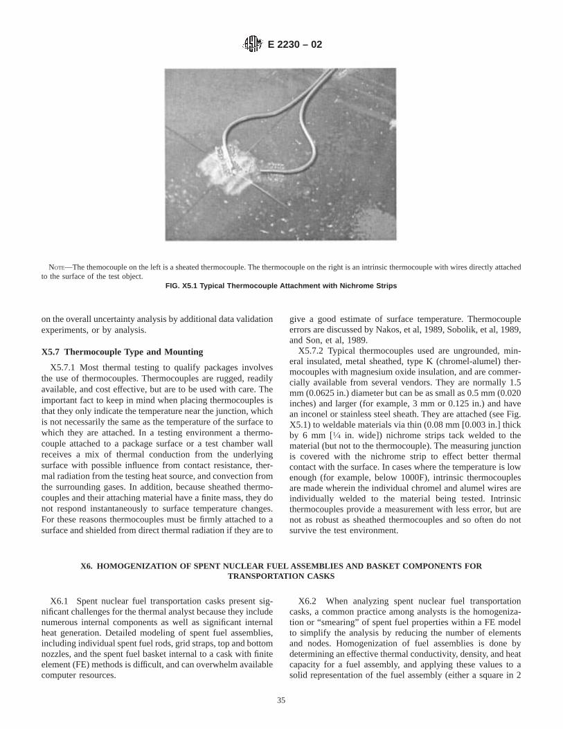
on the overall uncertainty analysis by additional data validationexperiments, or by analysis.
X5.7 Thermocouple Type and Mounting
X5.7.1 Most thermal testing to qualify packages involvesthe use of thermocouples. Thermocouples are rugged, readilyavailable, and cost effective, but are to be used with care. Theimportant fact to keep in mind when placing thermocouples isthat they only indicate the temperature near the junction, whichis not necessarily the same as the temperature of the surface towhich they are attached. In a testing environment a thermo-couple attached to a package surface or a test chamber wallreceives a mix of thermal conduction from the underlyingsurface with possible influence from contact resistance, ther-mal radiation from the testing heat source, and convection fromthe surrounding gases. In addition, because sheathed thermo-couples and their attaching material have a finite mass, they donot respond instantaneously to surface temperature changes.For these reasons thermocouples must be firmly attached to asurface and shielded from direct thermal radiation if they are to
give a good estimate of surface temperature. Thermocoupleerrors are discussed by Nakos, et al, 1989, Sobolik, et al, 1989,and Son, et al, 1989.
X5.7.2 Typical thermocouples used are ungrounded, min-eral insulated, metal sheathed, type K (chromel-alumel) ther-mocouples with magnesium oxide insulation, and are commer-cially available from several vendors. They are normally 1.5mm (0.0625 in.) diameter but can be as small as 0.5 mm (0.020inches) and larger (for example, 3 mm or 0.125 in.) and havean inconel or stainless steel sheath. They are attached (see Fig.X5.1) to weldable materials via thin (0.08 mm [0.003 in.] thickby 6 mm [1⁄4 in. wide]) nichrome strips tack welded to thematerial (but not to the thermocouple). The measuring junctionis covered with the nichrome strip to effect better thermalcontact with the surface. In cases where the temperature is lowenough (for example, below 1000F), intrinsic thermocouplesare made wherein the individual chromel and alumel wires areindividually welded to the material being tested. Intrinsicthermocouples provide a measurement with less error, but arenot as robust as sheathed thermocouples and so often do notsurvive the test environment.
X6. HOMOGENIZATION OF SPENT NUCLEAR FUEL ASSEMBLIES AND BASKET COMPONENTS FORTRANSPORTATION CASKS
X6.1 Spent nuclear fuel transportation casks present sig-nificant challenges for the thermal analyst because they includenumerous internal components as well as significant internalheat generation. Detailed modeling of spent fuel assemblies,including individual spent fuel rods, grid straps, top and bottomnozzles, and the spent fuel basket internal to a cask with finiteelement (FE) methods is difficult, and can overwhelm availablecomputer resources.
X6.2 When analyzing spent nuclear fuel transportationcasks, a common practice among analysts is the homogeniza-tion or “smearing” of spent fuel properties within a FE modelto simplify the analysis by reducing the number of elementsand nodes. Homogenization of fuel assemblies is done bydetermining an effective thermal conductivity, density, and heatcapacity for a fuel assembly, and applying these values to asolid representation of the fuel assembly (either a square in 2
NOTE—The themocouple on the left is a sheated thermocouple. The thermocouple on the right is an intrinsic thermocouple with wires directly attachedto the surface of the test object.
FIG. X5.1 Typical Thermocouple Attachment with Nichrome Strips
E 2230 – 02
35
dimensions or a rectangular solid in 3 dimensions). The solidrepresentation will have less detail and therefore fewer ele-ments and nodes than would a detailed fuel assembly model.Some analysts will go one step further and homogenize theentire fuel region including the basket structure. This practicewill be successful in estimating bounding fuel region tempera-tures, but is not as accurate for determining precise fuelcladding temperatures.
X6.3 The challenge to the analyst is to accurately determinethe effective properties of the solid homogenized fuel assemblymodels, and assure that the model is a correct representation ofthe actual fuel assembly thermal characteristics. There areseveral different methods for determining the effective proper-ties for analytic fuel models, some of which will be reviewedhere. The reference list for this section provides severalreferences that describe the different methods in depth.
X6.4 In general, a successful homogenization of fuelassemblies will be based on successful benchmarks againsttemperature data taken from actual spent nuclear fuel assem-blies stored in storage casks with the effects of orientationtaken into consideration. The basic steps for creating a homog-enized fuel model are as follows:
X6.5 Overall Approach for Developing Homogenized Mod-els of Fuel Assemblies:
X6.5.1 First, a detailed model of the fuel assemblies (in-cluding fuel pellets, fuel cladding and rod fill gasses) and thefuel basket is developed to account for all heat transfermechanisms involved, including conduction, radiation and,where appropriate, convection. This model shall be verifiedagainst spent fuel temperature data to ensure that it provides anaccurate fuel assembly and basket temperature distribution.
X6.5.2 The next step is to calculate an effective conductivityfor the simplified geometry (usually a square area or arectangular volume) that will replace the detailed fuel assemblymodel. This is commonly done by varying the temperature ofthe basket cell wall in which the fuel assembly resides andusing the temperature difference between the hottest fuel rodand the cell wall to calculate the effective conductivity. Densityand specific heat are often averaged and then applied to thearea or volume representing the homogenized fuel assembly.
X6.5.3 Finally, the effective conductivity and average den-sity region shall be modeled to assure that the temperatureprofile closely matches that of the original detailed fuel model.Note that when fuel is homogenized the temperature estimatesmade for fuel cladding are less accurate than with a detailedfuel model. This shall be taken into account when attempting todraw conclusions about peak fuel cladding temperatures fromhomogenized fuel models.
X6.6 Methods for Determining Fuel Temperatures andEffective Conductivity Values:
X6.6.1 One of the older correlations for determining peakfuel cladding temperatures and effective thermal conductivityvalues for spent fuel is the Wooton-Epstein (W-E) correlation(See Wooten and Epstein, 1963). Introduced in 1963, thiscorrelation has been used by many cask designers since that
time. The W-E correlation is based upon experiments con-ducted on a single fuel assembly in air, made up of 306 solidstainless steel tubes (0.34 in. in diameter) arranged in a 17318 assembly on 0.422 in. centers. The assembly was approxi-mately 8 ft long. The tubes were heated via resistance heatingto simulate a decay heat of 8 kW (equivalent to 3 months ofcooling). The assembly was centered in a steel pipe with aninside diameter of 1 ft. An annulus outside the pipe was filledwith coolant to maintain a constant wall temperature. In theirpaper, Wooton and Epstein stated that for a given assemblydecay heat, the correlation would over-predict the fuel claddingtemperature. Currently the W-E correlation is considered to bemore conservative than necessary for thermal analysis of spentfuel assemblies under most conditions of storage.
X6.6.2 Manteufel and Todreas, 1994, describe a method fordetermining the effective thermal conductivity of spent fuelassemblies by defining a unique effective thermal conductivityfor interior and edge regions of individual fuel assemblies. Thismodel is based on conduction and radiation within the fuelassembly. Convection effects are added to the correlation forcertain temperature regimes. The model is applied to bothPWR and BWR fuel assemblies. The model is compared withfive sets of data for experimental validation, as well as withpredictions generated by the engine maintenance, assembly,and disassembly (E-MAD) and W-E correlations.
X6.6.3 Thomas and Carlson, 1999, present an informativediscussion of heat transfer within a fuel assembly and betweena fuel assembly and its surrounding environment. The study intheir paper presented a discussion of the Fuel Temperature Test(FTT) experimental series (Bates, 1986) which was conductedfor a single Westinghouse 153 15 fuel assembly with a decayheat load of 1.17 kW, in vacuum, air, and helium backfillconditions.
X6.6.4 The authors used the TOPAZ3D finite elementanalysis (FEA) code to model the test set-up by determining aneffective thermal conductivity for the fuel region, first for thevacuum case. They then used those values to determine thehelium and air backfill cases. They adjusted the conductivityvalues of the air and helium to account for any convection thatmight be present, to closely match the values presented in theFTT experiments. Results and a discussion of those results areprovided in their report.
X6.6.5 The authors included a comparison of the resultswith the effective thermal conductivity model of Manteufel andTodreas and determined that their model produced slightlylower (more conservative) effective thermal conductivity val-ues for the same conditions present in the FTT experiments.The correlation that was developed by the authors was devel-oped for specific spent fuel parameters, and would not beapplicable to spent fuel types with different values for param-eters such as burn-up, cooling time, decay heat, etc.
X6.6.6 In a report prepared for the Department of Energy,Bahney and Lotz, 1996, review current techniques for fuelhomogenization and describe a method of determining fueleffective thermal conductivity with the use of FEA. Detailedmodels of fuel elements were developed for several PWR andBWR fuel assembly sizes and analyzed for a range of heat
E 2230 – 02
36

loads and fuel basket temperatures. Effective thermal conduc-tivity values were then determined for individual assembliesfrom the fuel temperature results. This paper provides asubstantive discussion of the W-E correlation, and includes acalculation of peak cladding temperatures with use of thecorrelation. The fuel cladding temperatures calculated with theW-E correlation were found to be greater than those calculatedwith the FE method for the same geometry and heat loadvalues. The paper provides the derivation of a formula foreffective conductivity of a homogenized fuel assembly, andprovides values for different fuel element sizes. These effectiveconductivity values are compared to conductivity values de-rived from the W-E correlation. For the most part, the W-Econductivity values were lower (more conservative) than thevalues calculated based on the FE method.
X6.6.7 In the 1980’s a series of tests was conducted onspent fuel storage casks at the Idaho National EngineeringLaboratories (INEL). The Pacific Northwest Laboratories(PNL) in cooperation with the Electrical Power ResearchInstitute (EPRI) conducted the tests and published the results.Several different casks were tested including the Castor-V/21(Dziadosz, et al, 1986), the Transnuclear(TN)-24P (Creer, et al,1987), the VSC-17 (McKinnon, et al, 1992) and the MC-10(McKinnon, et al, 1987). These casks contained spent nuclearfuel assemblies of various sizes and burn-ups, removed froman operating nuclear reactor. Temperature measurements weretaken with the casks in different orientations and using differentfill gasses. PNL used this data to validate their COBRA-SFS
code, which is a best-estimate finite difference code thatprovides accurate spent fuel cladding temperatures for almostany type of spent fuel assembly in a cask. The data from thesetests has been used by other analysts to develop accuratehomogenized spent fuel assembly thermal models.
X6.6.8 Sanders, et al, 1992, described a method of deter-mining spent fuel effective thermal conductivity that utilizedthe TOPAZ 2D finite element code. Data from the EPRI reportsmentioned above was used to develop a fuel pin model andthen a full fuel element model. From the fuel element model,an effective thermal conductivity was developed and used topredict maximum fuel cladding temperatures. The predictedtemperatures were only slightly above those reported in theEPRI reports for a similar fuel assembly.
X6.7 Conclusion—Homogenization of spent fuel for ther-mal analysis is a fairly straightforward process that yieldssignificant savings in analysis time, while providing accurateresults. The methods described in this appendix provide theanalyst with the tools to build an accurate FE model for spentfuel assemblies. A careful review of the methods summarizedhere is encouraged, as the details of each method need to beunderstood by the analyst if they are to be successful inbuilding accurate homogenized fuel models. Models developedby an analyst shall be verified against the best available data fora given fuel assembly. Verification will provide the necessarysupport for an analysis that will be reviewed by a regulatorybody.
REFERENCES
(1) Arpaci, V. S., “Conduction Heat Transfer,” Addison-Wesley Publish-ing Co., 1966.
(2) Bahney III, R. H. and Lotz, T. L., “Spent Nuclear Fuel EffectiveThermal Conductivity Report,” Prepared for U.S. Department ofEnergy, Contract #: DE-AC01-91RW00134, July 11, 1996.
(3) Creer, J. M., et. al, “TN-24P PWR Spent Fuel Storage Cask: Testingand Analysis,” EPRI NP-5128, Electric Power Research Institute, PaloAlto, California, 1987.
(4) Dziadosz, D. A., et al, “Castor-V/21 PWR Spent Fuel Storage Cask:Testing and Analysis,” EPRI NP-4887, Electric Power ResearchInstitute, Palo Alto, California, 1986.
(5) Glass, R. E., “Sample Problem Manual for Benchmarking of CaskAnalysis Codes,” SAND88-0190, Sandia National Laboratories, Al-buquerque, 1988.
(6) Gregory, J. J., Mata Jr., R. and Keltner, N. R., “Thermal Measurementsin a Series of Large Pool Fires,” SAND 85-0196, Sandia NationalLaboratories, Albuqerque, NM, 1987.
(7) Koski, J. A., Gritzo, L. A., Kent, L. A., and Wix, S. D., “ActivelyCooled Calorimeter Measurements and Environment Characterizationin a Large Pool Fire,”Fire and Materials, Vol 20, No. 2, March-April,1996, pp. 69–78.
(8) McKinnon, M. A., et. al, “The MC-10 PWR Spent Fuel Storage Cask:Testing and Analysis,” EPRI NP-5268, Electric Power ResearchInstitute, Palo Alto, California, 1987.
(9) McKinnon, M. A., et. al, “Performance Testing and Analyses of theVSC-17 Ventilated Concrete Cask,” PNL-7839, Pacific NorthwestLaboratory, Richland, Washington, May 1992.
(10) Manteufel, R. D. and Todreas, N. E., “Effective Thermal Conductiv-ity and Edge Conductance Model for a Spent-Fuel Assembly,”Nuclear Technology, Vol 105, Mar. 1994, pp. 421–440.
(11) Nakos, J. T., Gill, W., and Keltner, N. R., “An Analysis of FlameTemperature Measurements Using Sheathed Thermocouples in JP-4Pool Fires,”Thermal Engineering, Vol 5, John R. Lloyd and YasuoKurosaki,ed., ASME, NewYork, 1991, pp. 283-289. (Proceedings ofthe ASME/JSME Thermal Engineering, Joint Conference, Reno,Nevada, March 17-22, 1991.)
(12) Shah, V. L., “Estimation of Maximum Temperature in a PackageSubjected to Hypothetical-Accident Thermal Test Conditions,” ANL-96/12, Argonne National Laboratory, Argonne, IL, 1996.
(13) Sanders, T. L., et al, “A Method for Determining the Spent-FuelContribution to Transport Cask Containment Requirements,”SAND90-2406, Sandia National Laboratories, November 1992, pp.II–122 to II–153.
(14) Schneider, M. E. and Kent, L. A., “Measurements of Gas Velocitiesand Temperatures in a Large Open Pool Fire,”Fire Technology, Vol25, No. 1, February 1989.
(15) Siegel, R. and Howell, J. R.,Thermal Radiation Heat Transfer,Taylor and Francis Group, 4th Edition, 2001.
(16) Sobolik, K. B., Keltner, N. R., and Beck, J. V., “Measurement Errorsfor Thermocouples Attached to Thin Plates: Application to Heat FluxMeasurement Devices,”Heat Transfer Measurements, Analysis, andFlow Visualization, HTD-112, R. K. Shah, Ed., ASME, New York,H00504, 1989.
(17) Son, S. F., Queiroz, M., and Wood, C. G., “Compensation ofThermocouples for Thermal Inertia Effects Using a Digital Decon-volution,” Heat Transfer Phenomena in Radiation, Combustion, andFires, R. K. Shah, Ed., ASME, New York, HTD-106, 1989. (Pre-sented at The 1989 National Heat Transfer Conference, Philadelphia,PA, August 6-9, 1989.)
(18) Thomas, G. R. and Carlson, R. W., “Evaluation of the Use of
E 2230 – 02
37

Homogenized Fuel Assemblies in the Thermal Analysis of Spent FuelStorage Casks,” UCRL-ID-134567, Lawrence Livermore NationalLaboratory, July 1999.
(19) Van Sant, J. H. and Carlson, R. W., Fischer, L. E., and Hovingh, J.,“A Guide for Thermal Testing Transport Packages for RadioactiveMaterial—Hypothetical Accident Conditions,” Lawrence LivermoreNational Laboratory, Livermore, CA, UCRL-ID-110445, 1993.
(20) Wooton, R. O., Epstein, H. M., “Heat Transfer from a Parallel RodFuel Element in a Shipping Container,” Unpublished report, BatelleMemorial Institute (1963); See also Bucholz, J.A., “Scoping DesignAnalysis for Optimized Shipping Casks Containing 1-,2-,3-,5-,7-, or10-Year-Old PWR Spent Fuel,” ORNL/CSD/TM-149, Appendix J,
Oak Ridge National Laboratory, 1983.(21) “Combination Test/Analysis Method Used to Demonstrate Compli-
ance to DOE Type B Packaging Thermal Test Requirements (30Minute Fire Test),” SG 140.1, United States Department of Energy,Albuquerque Field Office, Nuclear Explosive Division, Albuquerque,NM, February 10, 1992.
(22) “Safety Analysis Report for the 10-135 Radwaste Shipping Cask,”STD-R-02-019, Rev. 4, ATG, Inc., Oak Ridge, TN 37830, 1999.
(23) “Thermal Analysis System (TAS) User’s Manual Version 3,” HarvardThermal, Cambridge, MA, 1998.
(24) “Thermal Network Modeling Handbook,” K&K Associates, Version97.001, 1997.
ASTM International takes no position respecting the validity of any patent rights asserted in connection with any item mentionedin this standard. Users of this standard are expressly advised that determination of the validity of any such patent rights, and the riskof infringement of such rights, are entirely their own responsibility.
This standard is subject to revision at any time by the responsible technical committee and must be reviewed every five years andif not revised, either reapproved or withdrawn. Your comments are invited either for revision of this standard or for additional standardsand should be addressed to ASTM International Headquarters. Your comments will receive careful consideration at a meeting of theresponsible technical committee, which you may attend. If you feel that your comments have not received a fair hearing you shouldmake your views known to the ASTM Committee on Standards, at the address shown below.
This standard is copyrighted by ASTM International, 100 Barr Harbor Drive, PO Box C700, West Conshohocken, PA 19428-2959,United States. Individual reprints (single or multiple copies) of this standard may be obtained by contacting ASTM at the aboveaddress or at 610-832-9585 (phone), 610-832-9555 (fax), or [email protected] (e-mail); or through the ASTM website(www.astm.org).
E 2230 – 02
38
Related Documents