2013.09 / b DYNEO ® VARIABLE SPEED DRIVES Unidrive M variable speed drives LSRPM permanent magnet synchronous motors 0.75 to 85 kW Technical catalogue 5034 en -

Welcome message from author
This document is posted to help you gain knowledge. Please leave a comment to let me know what you think about it! Share it to your friends and learn new things together.
Transcript

2013.09 / b
DYNEO® VARIABLE SPEED DRIVES
Unidrive M variable speed drivesLSRPM permanent magnet synchronous motors
0.75 to 85 kW
Technical catalogue5034 en -
2
QUALITYMANAGEMENT
Certificate No. Q 05176 003
ENVIROMENTALMANAGEMENT
Certificate No. EMS 54446 003
Ethernet Onboard
SensorlessPermanent Magnet
Motor Control
SIL3Safety Integrity
Level
IEEE 1588Precision
Time Protocol
Emerson Industrial Automation - Dyneo® variable speed drives - 5034 en - 2013.09 / b
DYNEO® VARIABLE SPEED DRIVES Unidrive M variable speed drives/LSRPM permanent magnet synchronous motors
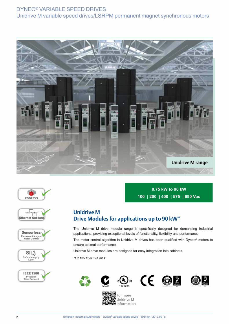
Unidrive MDrive Modules for applications up to 90 kW*
The Unidrive M drive module range is specifically designed for demanding industrial applications, providing exceptional levels of functionality, flexibility and performance.
The motor control algorithm in Unidrive M drives has been qualified with Dyneo® motors to ensure optimal performance.
Unidrive M drive modules are designed for easy integration into cabinets.
*1.2 MW from mid 2014
For more Unidrive M information
0.75 kW to 90 kW100 | 200 | 400 | 575 | 690 Vac
Unidrive M range

3Emerson Industrial Automation - Dyneo® variable speed drives - 5034 en - 2013.09 / b
DYNEO® VARIABLE SPEED DRIVES
Unidrive M variable speed drives/LSRPM permanent magnet synchronous motors
On the purchase price - Reduction in the weight and dimensions of the driven machine: up to 3 frame sizes smaller- Simplification through elimination of transmission devices (pulleys, belts, etc)- Longer service life: Lower bearing temperature, etc
On energy bills: High efficiency over the entire speed range
On maintenance: Less stress on the mechanism
Exceptional savings
- Constant torque over the entire speed range- Optimised power with centrifugal torque operation
Performance
Alliance of magnet rotor technology and the asynchronous motor’s tried and tested mechanism
Innovation you can place your trust in
LSRPM range
50 kWh
65 kWh
80 kWh
85 kWh
100 kWhOriginal solution
Mechanical optimisation
IE3 motors
Variable speed & IE3 motors
ENERGY SAVINGS
Modularity- Adapt to any application when used in combination with a 3000 range geared motor
0.75 kW to 400 kW
Guaranteed Availability !DELIVERY TIMES EX-WORKS: 5, 10 or 15 working days on a selection of drive systems
4 Emerson Industrial Automation - Dyneo® variable speed drives - 5034 en - 2013.09 / b
DYNEO® VARIABLE SPEED DRIVES
Unidrive M variable speed drives/LSRPM permanent magnet synchronous motors
Innovative solutions
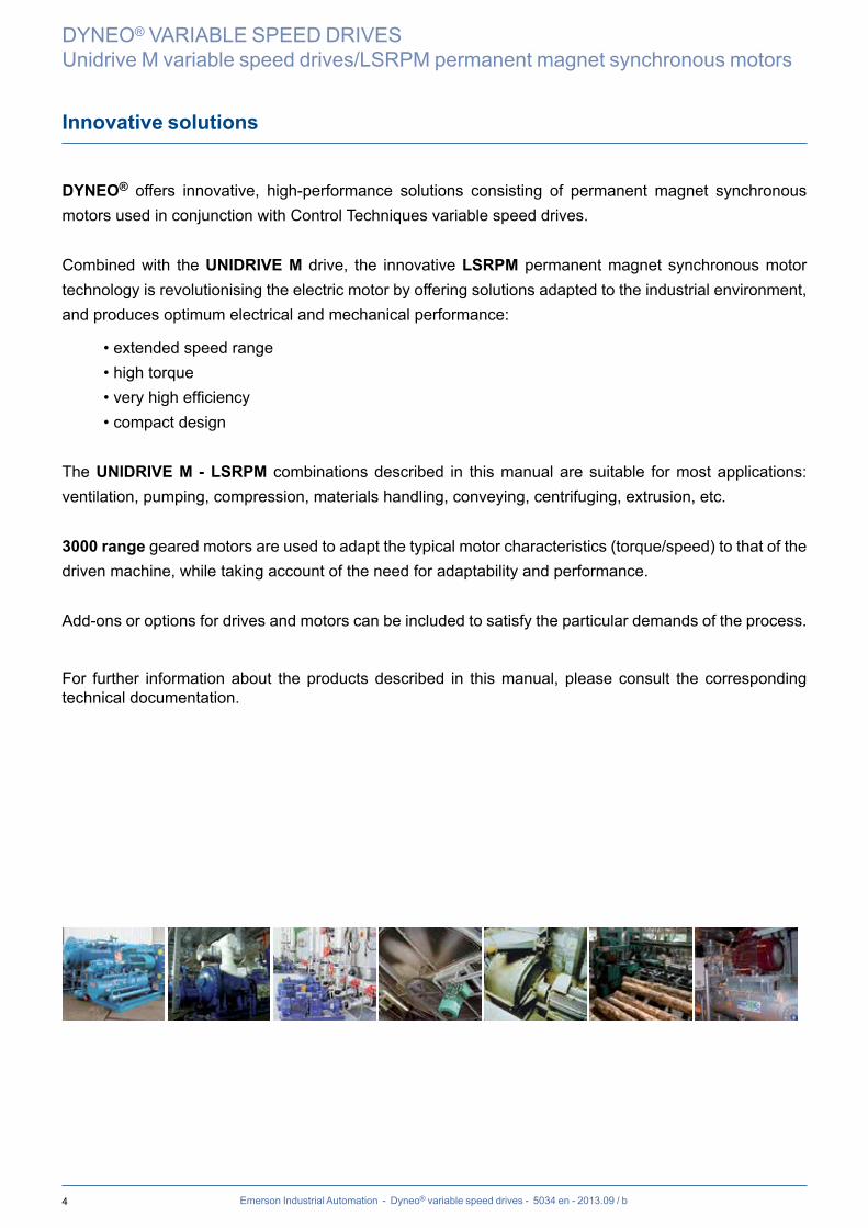
DYNEO® offers innovative, high-performance solutions consisting of permanent magnet synchronous motors used in conjunction with Control Techniques variable speed drives.
Combined with the UNIDRIVE M drive, the innovative LSRPM permanent magnet synchronous motor technology is revolutionising the electric motor by offering solutions adapted to the industrial environment, and produces optimum electrical and mechanical performance:
• extended speed range • high torque• very high efficiency• compact design
The UNIDRIVE M - LSRPM combinations described in this manual are suitable for most applications: ventilation, pumping, compression, materials handling, conveying, centrifuging, extrusion, etc.
3000 range geared motors are used to adapt the typical motor characteristics (torque/speed) to that of the driven machine, while taking account of the need for adaptability and performance.
Add-ons or options for drives and motors can be included to satisfy the particular demands of the process.
For further information about the products described in this manual, please consult the corresponding technical documentation.
5Emerson Industrial Automation - Dyneo® variable speed drives - 5034 en - 2013.09 / b
Contents
INTRODUCTIONModular offer .................................................................... 6-7
Unidrive M drive....................................................................8
LSRPM motors ....................................................................9
3000 range gearboxes combined with the LSRPM and Unidrive M ..................................................................10
Variable speed drive designation .......................................11
Selection method ................................................................12
PERFORMANCEEfficiency ...........................................................................13
5500 range - 0 to 5500 min-1
Torque from 0 to 147 N.m ...................................................14
4500 range - 0 to 4500 min-1 Torque from 0 to 170 N.m ...................................................15
3600 range - 0 to 3600 min-1
Torque from 0 to 225 N.m ...................................................16
3000 range - 0 to 3000 min-1
Torque from 0 to 271 N.m ...................................................17
2400 range - 0 to 2400 min-1
Torque from 0 to 320 N.m ...................................................18
1800 range - 0 to 1800 min-1
Torque from 0 to 450 N.m ...................................................19
1500 range - 0 to 1500 min-1
Torque from 0 to 550 N.m .............................................. 20-21
900 range - 0 to 900 min-1
Torque from 0 to 900 N.m ............................................. 22-23
750 range - 0 to 750 min-1
Torque from 0 to 1100 N.m ........................................... 24-25
SELECTION5500 range ........................................................................26
4500 range ........................................................................27
3600 range ........................................................................28
3000 range ........................................................................29
2400 range ........................................................................30
1800 range ........................................................................31
1500 range ........................................................................32
900 range ..........................................................................33
750 range ..........................................................................34
INSTALLATION AND OPTIONS
General information ............................................................36
Installation .................................................................... 37-38
Reinforced insulation ..........................................................39
Selection of position sensor................................................40
Encoders ............................................................................41
Forced ventilation - Cable glands .......................................42
Thermal protection..............................................................43
DRIVE DIMENSIONS
Unidrive M ..........................................................................44
MOTOR DIMENSIONS
Shaft extensions .................................................................45
Foot mounted IM B3 ...........................................................46
Foot and flange mounted IM B35 .......................................47
Flange mounted IM B5 - IM V1...........................................48
Foot and face mounted IM B34 ..........................................49
Face mounted IM B14 ........................................................50
Motor with options ..............................................................51
MOTOR CONSTRUCTION
Definition of “Index of Protection” (IP/IK) ............................52
External finishing ................................................................53
Mounting arrangements......................................................54
Bearings and lubrication .....................................................55
Connection .........................................................................56
Motor vibration levels..........................................................57
GENERAL INFORMATION
Quality commitment ............................................................58
Standards and approvals.............................................. 59-60
Nameplates ........................................................................61
Configurator ........................................................................62
DYNEO® VARIABLE SPEED DRIVES
Unidrive M variable speed drives/LSRPM permanent magnet synchronous motors
6 Emerson Industrial Automation - Dyneo® variable speed drives - 5034 en - 2013.09 / b
DYNEO® VARIABLE SPEED DRIVES
Unidrive M variable speed drives/LSRPM permanent magnet synchronous motorsIntroduction
Modular offer
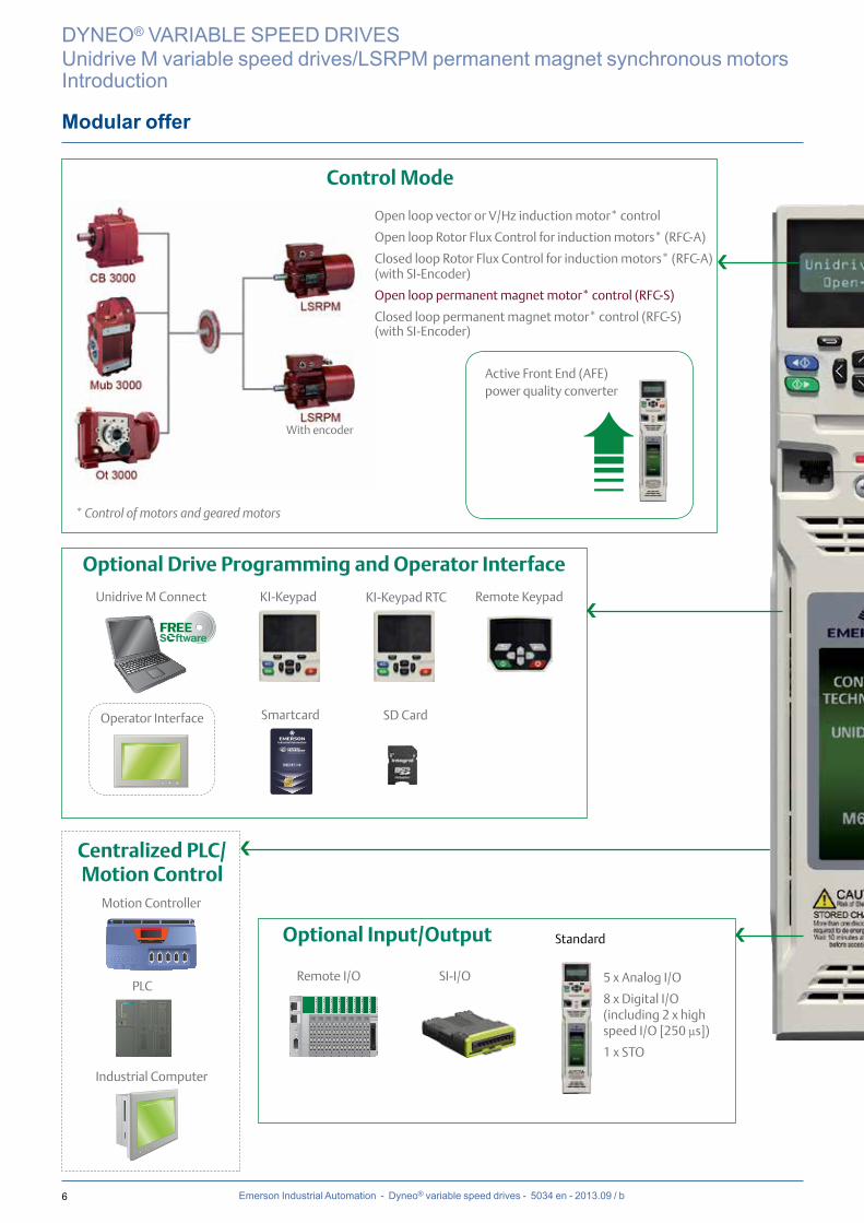
Open loop vector or V/Hz induction motor* control
Open loop Rotor Flux Control for induction motors* (RFC-A)
Closed loop Rotor Flux Control for induction motors* (RFC-A)(with SI-Encoder)
Open loop permanent magnet motor* control (RFC-S)
Closed loop permanent magnet motor* control (RFC-S)(with SI-Encoder)
Active Front End (AFE) power quality converter
Operator Interface
Remote I/O
Standard
Motion Controller
PLC
Industrial Computer
SI-I/O 5 x Analog I/O
8 x Digital I/O (including 2 x high speed I/O [250 μs])
1 x STO
Unidrive M Connect KI-Keypad
With encoder
KI-Keypad RTC
Smartcard SD Card
Remote Keypad
www.controltechniques.com
SFCPU314C-2 DP
BF
DC5V
FRCE
RUN
STOPPUSH
RUNSTOPMRES
0
1
2
3
4
5
6
7
IN IN OUTDI+2 DI+0
DI+1
D0+0
D0+1
DI8xDC24VAI5/A02x12Bit DI16/D016xDC24V
0
1
2
3
4
5
6
7
0
1
2
3
4
5
6
7
0
1
2
3
4
5
6
7
0
1
2
3
4
5
6
7
Control Mode
Optional Drive Programming and Operator Interface
Optional Input/Output
Centralized PLC/Motion Control
❯
* Control of motors and geared motors
❯
❯
❯
7Emerson Industrial Automation - Dyneo® variable speed drives - 5034 en - 2013.09 / b
Modular offer
DYNEO® VARIABLE SPEED DRIVES
Unidrive M variable speed drives/LSRPM permanent magnet synchronous motorsIntroduction
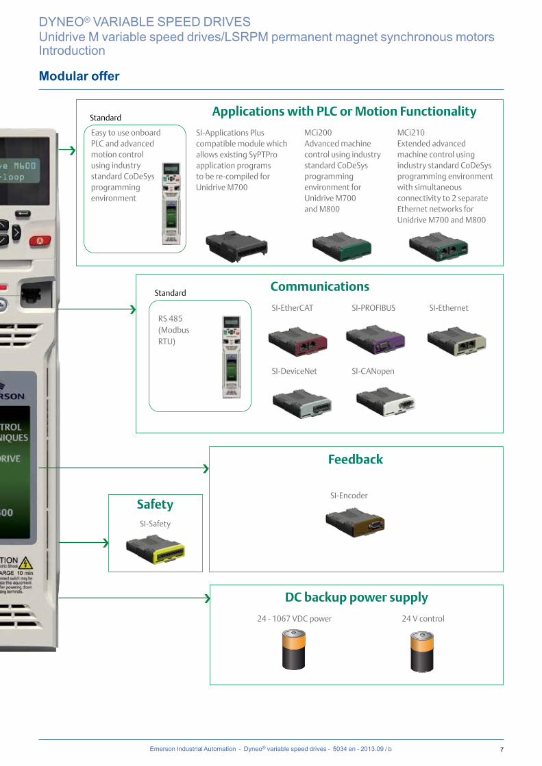
Communications
Standard
Standard
SI-Applications Plus compatible module which allows existing SyPTPro application programs to be re-compiled for Unidrive M700
SI-EtherCAT
SI-DeviceNet
SI-PROFIBUS
SI-Encoder
SI-CANopen
SI-Ethernet
24 - 1067 VDC power 24 V control
SI-Safety
Easy to use onboard PLC and advanced motion control using industry standard CoDeSys programming environment
RS 485(ModbusRTU)
MCi200 Advanced machine control using industry standard CoDeSys programming environment forUnidrive M700 and M800
MCi210 Extended advanced machine control using industry standard CoDeSys programming environment with simultaneous connectivity to 2 separate Ethernet networks forUnidrive M700 and M800
Applications with PLC or Motion Functionality
Feedback
Safety
DC backup power supply
❯
❯
❯
❯
❯

8 Emerson Industrial Automation - Dyneo® variable speed drives - 5034 en - 2013.09 / b
Unidrive M drive
The Unidrive M is a universal drive, designed for controlling asynchronous, servo or synchronous motors such as LSRPM.This feature gives the Unidrive M a vast field of applications, and it has therefore been endowed with a level of performance and functionality to cope with the most demanding systems.
Heavy duty or normal duty:The Unidrive M continuous output current and maximum transient current depend on the operating conditions.
Heavy duty:To obtain the maximum transient overload current available (applications at constant torque, or at rated torque required at low speed), the continuous output current (Ico) is limited.
Normal duty:If the operating conditions are not very demanding (for example, centrifugal applications: fans, pumps, etc), the output current can be increased and a motor with a higher output power can be controlled. However, the maximum transient current is limited.
DYNEO® VARIABLE SPEED DRIVES
Unidrive M variable speed drives/LSRPM permanent magnet synchronous motorsIntroduction
Output selection tables at 40°C - Control mode RFC-SDrive type Normal duty Heavy duty
Unidrive M600/700/800
Continuous current (A) Peak current Continuous current (A) RFC peak current
3 kHz 4 kHz 6 kHz (A) 3 kHz 4 kHz 6 kHz (A)
034 00025 3.4 3.7 2.5 5
034 00031 4.5 4.9 3.1 6.2
034 00045 6.2 6.8 4.5 9
034 00062 7.7 8.4 6.2 12.4
034 00078 10.4 11.4 7.8 15.6
034 00100 12.3 13.5 10 9.2 20
044 00150 18.5 20.3 15 30
044 00172 24 21.8 26.4 17.2 16.1 34.4
054 00270 30 25.8 33.0 25.4 23.7 20.3 54
054 00300 31 30.7 34.1 30 29.7 24 66
064 00350 38 41.8 35 70
064 00420 48 52.8 42 35.0 84
064 00470 63.0 57.0 48 69.3 46 42 35.0 94
074 00660 79 86.9 66 57 132
074 00770 94 103.4 77 70 59 154
074 01000 112 95 123.2 100 88 73 200
084 01340 155 170.5 134 130 109 268
084 01570 184 169 202.4 157 143 121 314
9Emerson Industrial Automation - Dyneo® variable speed drives - 5034 en - 2013.09 / b
LSRPM motors
DYNEO® VARIABLE SPEED DRIVES
Unidrive M variable speed drives/LSRPM permanent magnet synchronous motorsIntroduction
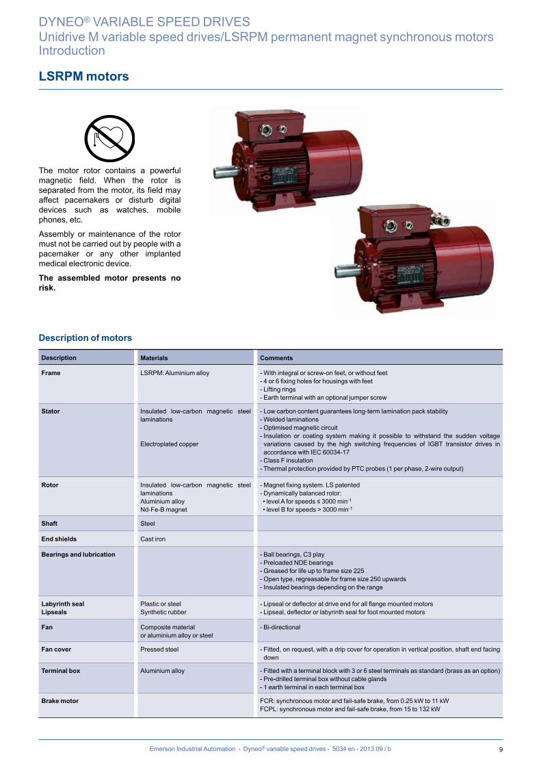
Description of motors
Description Materials Comments
Frame LSRPM: Aluminium alloy - With integral or screw-on feet, or without feet- 4 or 6 fixing holes for housings with feet- Lifting rings - Earth terminal with an optional jumper screw
Stator Insulated low-carbon magnetic steel laminations
Electroplated copper
- Low carbon content guarantees long-term lamination pack stability- Welded laminations- Optimised magnetic circuit- Insulation or coating system making it possible to withstand the sudden voltage variations caused by the high switching frequencies of IGBT transistor drives in accordance with IEC 60034-17
- Class F insulation- Thermal protection provided by PTC probes (1 per phase, 2-wire output)
Rotor Insulated low-carbon magnetic steel laminationsAluminium alloyNd-Fe-B magnet
- Magnet fixing system. LS patented- Dynamically balanced rotor: • level A for speeds ≤ 3000 min-1
• level B for speeds > 3000 min-1
Shaft Steel
End shields Cast iron
Bearings and lubrication - Ball bearings, C3 play- Preloaded NDE bearings- Greased for life up to frame size 225- Open type, regreasable for frame size 250 upwards- Insulated bearings depending on the range
Labyrinth sealLipseals
Plastic or steelSynthetic rubber
- Lipseal or deflector at drive end for all flange mounted motors- Lipseal, deflector or labyrinth seal for foot mounted motors
Fan Composite material or aluminium alloy or steel
- Bi-directional
Fan cover Pressed steel - Fitted, on request, with a drip cover for operation in vertical position, shaft end facing down
Terminal box Aluminium alloy - Fitted with a terminal block with 3 or 6 steel terminals as standard (brass as an option)- Pre-drilled terminal box without cable glands- 1 earth terminal in each terminal box
Brake motor FCR: synchronous motor and fail-safe brake, from 0.25 kW to 11 kWFCPL: synchronous motor and fail-safe brake, from 15 to 132 kW
The motor rotor contains a powerful magnetic field. When the rotor is separated from the motor, its field may affect pacemakers or disturb digital devices such as watches, mobile phones, etc.
Assembly or maintenance of the rotor must not be carried out by people with a pacemaker or any other implanted medical electronic device.
The assembled motor presents no risk.
10 Emerson Industrial Automation - Dyneo® variable speed drives - 5034 en - 2013.09 / b
3000 range gearboxes combined with the LSRPM and Unidrive M
DYNEO® VARIABLE SPEED DRIVES
Unidrive M variable speed drives/LSRPM permanent magnet synchronous motorsIntroduction
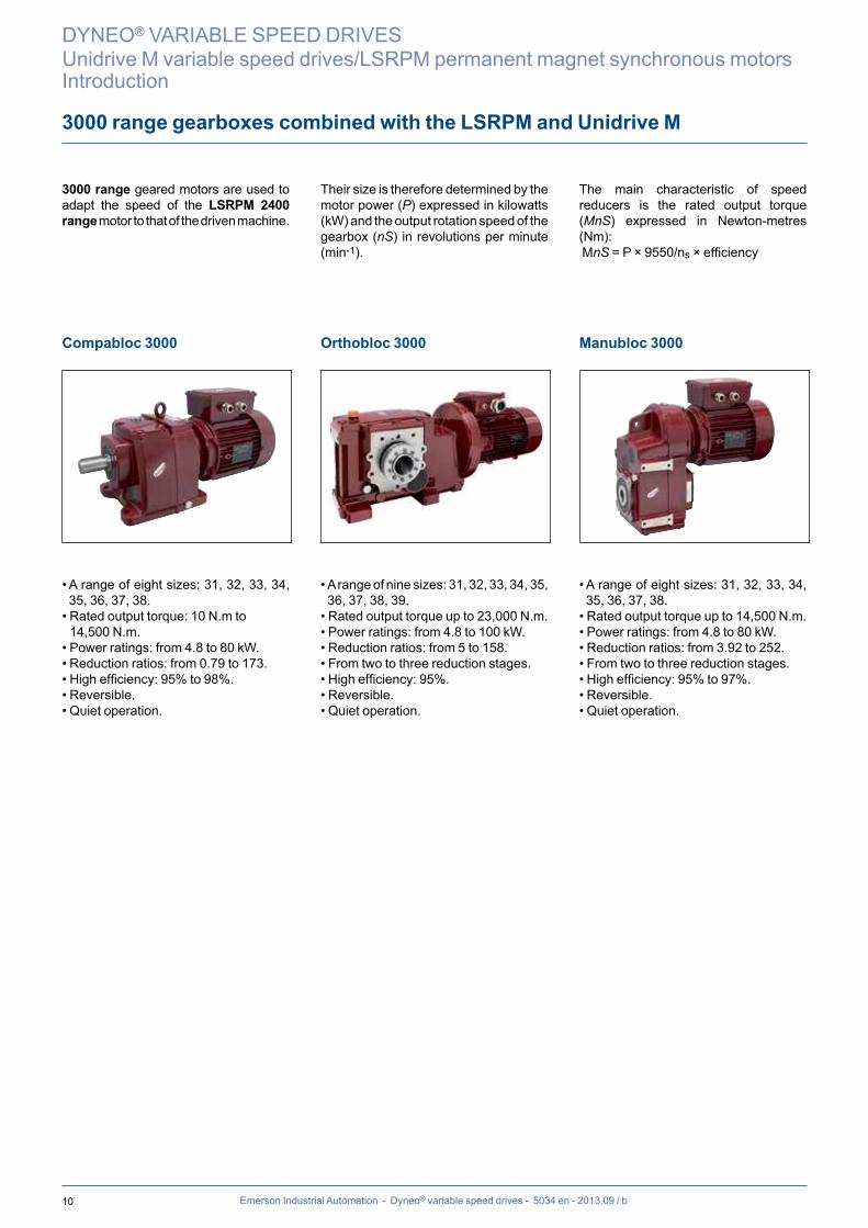
3000 range geared motors are used to adapt the speed of the LSRPM 2400 range motor to that of the driven machine.
Their size is therefore determined by the motor power (P) expressed in kilowatts (kW) and the output rotation speed of the gearbox (nS) in revolutions per minute (min-1).
The main characteristic of speed reducers is the rated output torque (MnS) expressed in Newton-metres (Nm): MnS = P × 9550/ns × efficiency
Compabloc 3000
• A range of eight sizes: 31, 32, 33, 34, 35, 36, 37, 38.
• Rated output torque: 10 N.m to 14,500 N.m.
• Power ratings: from 4.8 to 80 kW.• Reduction ratios: from 0.79 to 173.• High efficiency: 95% to 98%.• Reversible.• Quiet operation.
Orthobloc 3000
• A range of nine sizes: 31, 32, 33, 34, 35, 36, 37, 38, 39.
• Rated output torque up to 23,000 N.m.• Power ratings: from 4.8 to 100 kW.• Reduction ratios: from 5 to 158.• From two to three reduction stages.• High efficiency: 95%.• Reversible.• Quiet operation.
Manubloc 3000
• A range of eight sizes: 31, 32, 33, 34, 35, 36, 37, 38.
• Rated output torque up to 14,500 N.m.• Power ratings: from 4.8 to 80 kW.• Reduction ratios: from 3.92 to 252.• From two to three reduction stages.• High efficiency: 95% to 97%.• Reversible.• Quiet operation.

11Emerson Industrial Automation - Dyneo® variable speed drives - 5034 en - 2013.09 / b
Variable speed drive designation
DYNEO® VARIABLE SPEED DRIVES
Unidrive M variable speed drives/LSRPM permanent magnet synchronous motorsIntroduction
03 4 AMx0x-
Frame size
Voltage rating :2 : 200 V4 : 400 V5 : 575 V6 : 690 V
M600-
M700-M701-M702-M800-
High performance drive for inductionand sensorless PM motorsClass leading performance for induction,PM and servo motorsEthernet versionUnidrive SP replacementClass Ethernet and safety enhancedUltimate performance throughadvanced onboard motion control
Unidrive Range :
Derivative
00078
CurrentFrame & Volts
Current rating :Heavy duty rating x 10
Drive format :A = AC in AC out
Electrical specification
1500 LSRPM 200 L 25 kW IM 1001(IM B3) 400 V IP 55
Housing designationand manufacturer code
Ratedpower
Mounting arrangementsIEC 34-7
Power supply Protection
Seriesdesignation
Frame sizeRange
DRIVE
MOTOR
12
88
89
90
91
92
93
94
95
96
97
100
200
300
0 500 1000 1500 0 500 1000 1500
10 LSRPM 200 LU : 1500 min-1 / 55 kW / 110 A
11 LSRPM 200 L : 1500 min-1 / 40 kW / 83 A
12 LSRPM 200 L : 1500 min-1 / 33 kW / 75 A
13 LSRPM 200 L : 1500 min-1 / 25 kW / 56 A
1011
12
1388
89
90
91
92
93
94
95
96
97
100
200
300
0 500 1000 1500 0 500 1000 1500
10 LSRPM 200 LU : 1500 min-1 / 55 kW / 110 A
11 LSRPM 200 L : 1500 min-1 / 40 kW / 83 A
12 LSRPM 200 L : 1500 min-1 / 33 kW / 75 A
13 LSRPM 200 L : 1500 min-1 / 25 kW / 56 A
1011
12
13
Emerson Industrial Automation - Dyneo® variable speed drives - 5034 en - 2013.09 / b
27Leroy-Somer - Dyneo® variable speed drives - 4976 en - 2012.10 / a
1 The drive parameters must comply with the rated current values to ensure thermal control is maintained, as must the maximum current values to avoid the risk of demagnetisation
1500 range
Class F - DT80K - S1 Self-Cooled - Altitude 1000 m max - Ambient temperature 40°C max
Power supply upstream from the drive 400 V (in accordance with IEC 60034-1)
MOTOR DRIVE VARIABLE SPEED MOTOR Motor moment of inertia
Motor weight
Type
Rated power
Efficiency IEC 60034-2-1
2007Type Available
powerRated torque
Maximum torque/ Rated torque
Rated current1
Maximum current/ Rated current1
Minimum switching frequency
Efficiency
Pn η Unidrive M600 / M70x / M800
Pn Mn Mm/Mn In Im/In FD η J IM B3
kW 4/4 kW N.m A kHz 4/4 kg.m2 kg
LSRPM 90 SL 3 8703400045A
3 191,16
5,91,15
3 85,26 0,0032 1403400062A 1,50 1,49
LSRPM 90 L 3,7 89
03400045A 3,19 20,7 1,10 6,2 1,10
3 87,22 0,0051 1703400062A3,7 24
1,177,2
1,17
03400078A 1,50 1,50
LSRPM 100 L 4,5 90
03400062A 4,03 26 1,09 7,7 1,09
3 88,2 0,0066 1903400078A4,5 29
1,338,6
1,33
03400100A 1,50 1,50
LSRPM 100 L 5,2 9103400078A
5,2 331,15
9,91,15
3 89,2 0,0078 2403400100A 1,50 1,49
LSRPM 100 L 6 91,503400078A 5,72 36,3 1,10 10,4 1,10
3 89,7 0,009 2603400100A 6 38 1,24 10,9 1,24
LSRPM 132 M 8,2 91
04400150A 7,69 48,8 1,60 15 1,60
3 89,2 0,0165 4004400150A8,2 52
1,2716
1,27
04400172A 1,50 1,50
LSRPM 132 M 10,2 91,504400150A 9,48 60,4 1,10 18,5 1,10
3 89,7 0,0231 4404400172A 10,2 65 1,33 19,9 1,33
LSRPM 132 M 12 9204400150A 9,65 61,1 1,10 18,5 1,10
3 90,2 0,0311 4904400172A 12 76 1,15 23 1,15
LSRPM 160 MP 15,6 92,5 06400350A 15,6 99 1,50 30 1,50 3 90,7 0,0418 60
LSRPM 160 MP 19,2 93
06400350A 18,16 115,4 1,59 35 1,59
3 91,1 0,0514 6906400350A19,2 122
1,1337
1,13
06400420A 1,50 1,50
LSRPM 160 LR 22,8 93,5
06400420A 22,27 141,6 1,54 42 1,54
3 91,6 0,0626 7906400420A22,8 145
1,2343
1,23
06400470A 1,50 1,50
LSRPM 200 L 25 9406400420A 21,43 136,3 1,02 48 1,10
3 92,1 0,13 13506400470A 25 159 1,15 56 1,24
15.3 Drive limit
16 Motor limit
DYNEO® VARIABLE SPEED DRIVES
Unidrive M variable speed drives/LSRPM permanent magnet synchronous motorsSelection
Selection method
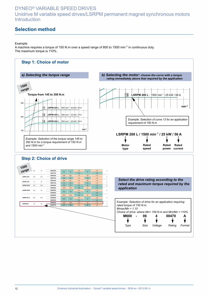
Example: Selection of curve 13 for an application requirement of 150 N.m
LSRPM 200 L / 1500 min-1 / 25 kW / 56 A
DYNEO® VARIABLE SPEED DRIVES
Unidrive M variable speed drives/LSRPM permanent magnet synchronous motorsIntroduction
1500range
1500range
Rated power
Motor type
Rated speed
Rated current
Example: Selection of drive for an application requiring rated torque of 150 N.m.Mmax/Mn = 1.10Choice of drive: where Mn= 159 N.m and Mm/Mn = 110% M600 - 06 4 00470 A
Type Size Voltage Rating Format
Example: Selection of the torque range 145 to 350 N.m for a torque requirement of 150 N.m and 1500 min-1
Example:A machine requires a torque of 150 N.m over a speed range of 800 to 1500 min-1 in continuous duty.The maximum torque is 110%.
Step 1: Choice of motor
a) Selecting the torque range b) Selecting the motor: choose the curve with a torque rating immediately above that required by the application
Torque from 145 to 350 N.m
Step 2: Choice of drive
Select the drive rating according to the rated and maximum torque required by the application
13Emerson Industrial Automation - Dyneo® variable speed drives - 5034 en - 2013.09 / b
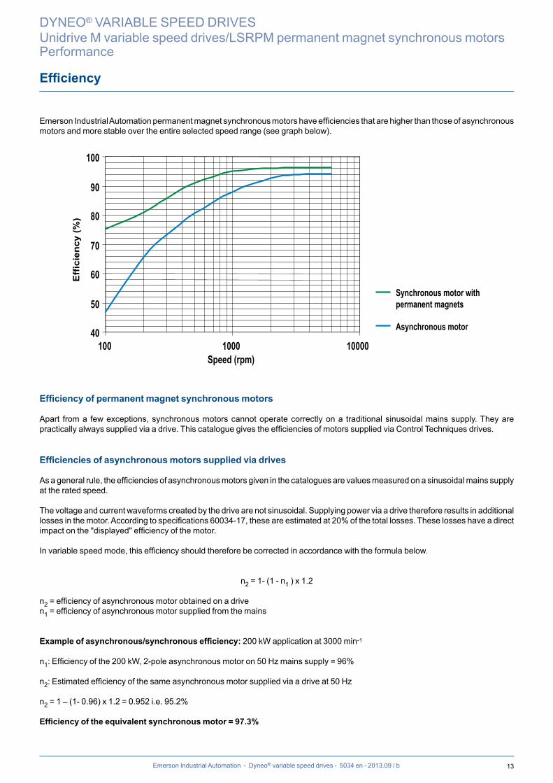
Emerson Industrial Automation permanent magnet synchronous motors have efficiencies that are higher than those of asynchronous motors and more stable over the entire selected speed range (see graph below).
40
50
60
70
80
90
100
100 1000 10000Speed (rpm)
Eff
icie
ncy
(%)
Synchronous motor with permanent magnets
Asynchronous motor
Efficiency of permanent magnet synchronous motors
Apart from a few exceptions, synchronous motors cannot operate correctly on a traditional sinusoidal mains supply. They are practically always supplied via a drive. This catalogue gives the efficiencies of motors supplied via Control Techniques drives.
Efficiencies of asynchronous motors supplied via drives
As a general rule, the efficiencies of asynchronous motors given in the catalogues are values measured on a sinusoidal mains supply at the rated speed.
The voltage and current waveforms created by the drive are not sinusoidal. Supplying power via a drive therefore results in additional losses in the motor. According to specifications 60034-17, these are estimated at 20% of the total losses. These losses have a direct impact on the "displayed" efficiency of the motor.
In variable speed mode, this efficiency should therefore be corrected in accordance with the formula below.
n2 = 1- (1 - n1 ) x 1.2
n2 = efficiency of asynchronous motor obtained on a driven1 = efficiency of asynchronous motor supplied from the mains
Example of asynchronous/synchronous efficiency: 200 kW application at 3000 min-1
n1: Efficiency of the 200 kW, 2-pole asynchronous motor on 50 Hz mains supply = 96%
n2: Estimated efficiency of the same asynchronous motor supplied via a drive at 50 Hz n2 = 1 – (1- 0.96) x 1.2 = 0.952 i.e. 95.2%
Efficiency of the equivalent synchronous motor = 97.3%
Efficiency
DYNEO® VARIABLE SPEED DRIVES
Unidrive M variable speed drives/LSRPM permanent magnet synchronous motorsPerformance
14
0 1000 2000 3000 4000 5000 6000 0 1000 2000 3000 4000 5000 600010
15
20
25
85
86
87
88
89
90
91
92
93
941513 1411 12
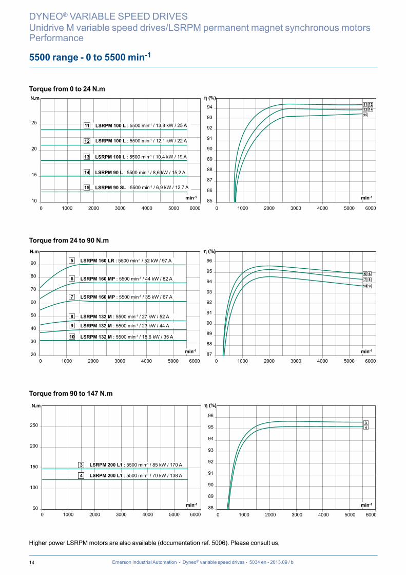
15 LSRPM 90 SL : 5500 min-1 / 6,9 kW / 12,7 A
14 LSRPM 90 L : 5500 min-1 / 8,6 kW / 15,2 A
13 LSRPM 100 L : 5500 min-1 / 10,4 kW / 19 A
12 LSRPM 100 L : 5500 min-1 / 12,1 kW / 22 A
11 LSRPM 100 L : 5500 min-1 / 13,8 kW / 25 A
0 1000 2000 3000 4000 5000 600020
30
40
50
60
70
80
90
0 1000 2000 3000 4000 5000 600087
89
91
93
95
88
90
92
94
96
10 LSRPM 132 M : 5500 min-1 / 18,6 kW / 35 A
9 LSRPM 132 M : 5500 min-1 / 23 kW / 44 A
8 LSRPM 132 M : 5500 min-1 / 27 kW / 52 A
7 LSRPM 160 MP : 5500 min-1 / 35 kW / 67 A
6 LSRPM 160 MP : 5500 min-1 / 44 kW / 82 A
5 LSRPM 160 LR : 5500 min-1 / 52 kW / 97 A
7 8
9
65
10
0 1000 2000 3000 4000 5000 6000 0 1000 2000 3000 4000 5000 600050
100
150
200
250
88
89
90
91
92
93
94
95
9634
3 LSRPM 200 L1 : 5500 min-1 / 85 kW / 170 A
4 LSRPM 200 L1 : 5500 min-1 / 70 kW / 138 A
Emerson Industrial Automation - Dyneo® variable speed drives - 5034 en - 2013.09 / b
DYNEO® VARIABLE SPEED DRIVES
Unidrive M variable speed drives/LSRPM permanent magnet synchronous motorsPerformance
5500 range - 0 to 5500 min-1
Torque from 0 to 24 N.m
Torque from 24 to 90 N.m
Torque from 90 to 147 N.m
Higher power LSRPM motors are also available (documentation ref. 5006). Please consult us.
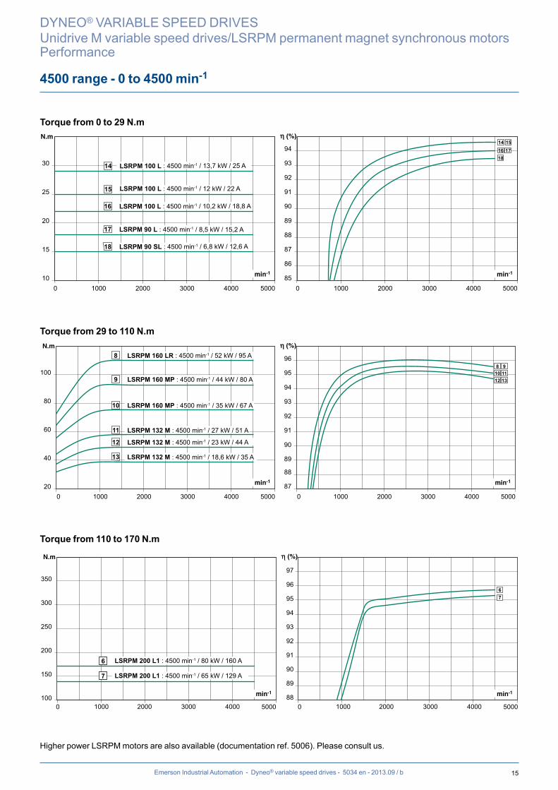
15
0 1000 2000 3000 4000 5000 0 1000 2000 3000 4000 500010
15
20
30
25
85
86
87
88
89
90
91
92
93
941816 1714 15
18 LSRPM 90 SL : 4500 min-1 / 6,8 kW / 12,6 A
17 LSRPM 90 L : 4500 min-1 / 8,5 kW / 15,2 A
16 LSRPM 100 L : 4500 min-1 / 10,2 kW / 18,8 A
15 LSRPM 100 L : 4500 min-1 / 12 kW / 22 A
14 LSRPM 100 L : 4500 min-1 / 13,7 kW / 25 A
0 1000 2000 3000 4000 5000 0 1000 2000 3000 4000 500020
40
60
80
100
87
89
91
93
95
88
90
92
94
96
1112 13
9810
13 LSRPM 132 M : 4500 min-1 / 18,6 kW / 35 A
12 LSRPM 132 M : 4500 min-1 / 23 kW / 44 A
11 LSRPM 132 M : 4500 min-1 / 27 kW / 51 A
10 LSRPM 160 MP : 4500 min-1 / 35 kW / 67 A
9 LSRPM 160 MP : 4500 min-1 / 44 kW / 80 A
8 LSRPM 160 LR : 4500 min-1 / 52 kW / 95 A
0 2000 3000 40001000 5000 0 2000 3000 40001000 5000100
150
200
250
300
350
88
89
90
91
92
93
94
95
96
97
67
6 LSRPM 200 L1 : 4500 min-1 / 80 kW / 160 A
7 LSRPM 200 L1 : 4500 min-1 / 65 kW / 129 A
Emerson Industrial Automation - Dyneo® variable speed drives - 5034 en - 2013.09 / b
DYNEO® VARIABLE SPEED DRIVES
Unidrive M variable speed drives/LSRPM permanent magnet synchronous motorsPerformance
4500 range - 0 to 4500 min-1
Torque from 0 to 29 N.m
Torque from 29 to 110 N.m
Torque from 110 to 170 N.m
Higher power LSRPM motors are also available (documentation ref. 5006). Please consult us.
16
0 300020001000 400010
15
20
25
30
35
80
82
84
86
88
90
92
94
0 300020001000 4000
23
2122
1920
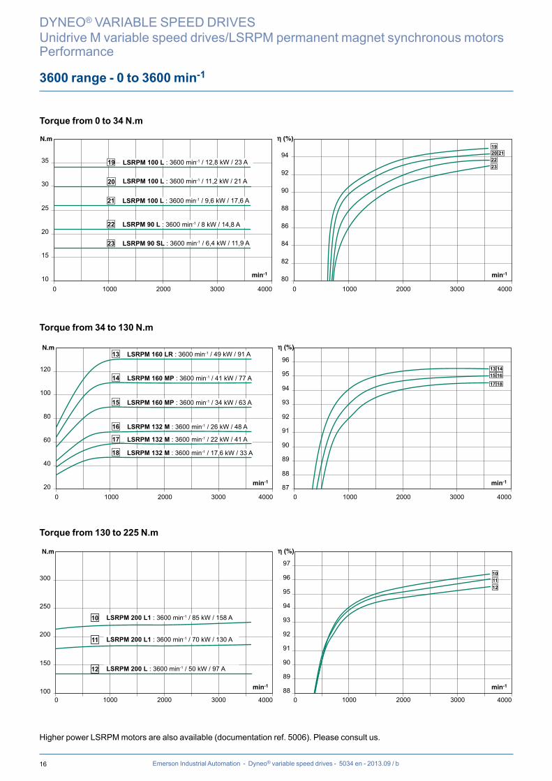
23 LSRPM 90 SL : 3600 min-1 / 6,4 kW / 11,9 A
22 LSRPM 90 L : 3600 min-1 / 8 kW / 14,8 A
21 LSRPM 100 L : 3600 min-1 / 9,6 kW / 17,6 A
20 LSRPM 100 L : 3600 min-1 / 11,2 kW / 21 A
19 LSRPM 100 L : 3600 min-1 / 12,8 kW / 23 A
20
40
60
80
100
120
87
89
91
93
95
88
90
92
94
96
0 300020001000 40000 300020001000 4000
16
17 18
151413
18 LSRPM 132 M : 3600 min-1 / 17,6 kW / 33 A
17 LSRPM 132 M : 3600 min-1 / 22 kW / 41 A
16 LSRPM 132 M : 3600 min-1 / 26 kW / 48 A
15 LSRPM 160 MP : 3600 min-1 / 34 kW / 63 A
14 LSRPM 160 MP : 3600 min-1 / 41 kW / 77 A
13 LSRPM 160 LR : 3600 min-1 / 49 kW / 91 A
0 1000 2000 3000 4000 0 1000 2000 3000 4000100
150
200
250
300
89
91
93
95
88
90
92
94
96
97101112
10 LSRPM 200 L1 : 3600 min-1 / 85 kW / 158 A
11 LSRPM 200 L1 : 3600 min-1 / 70 kW / 130 A
12 LSRPM 200 L : 3600 min-1 / 50 kW / 97 A
Emerson Industrial Automation - Dyneo® variable speed drives - 5034 en - 2013.09 / b
3600 range - 0 to 3600 min-1
DYNEO® VARIABLE SPEED DRIVES
Unidrive M variable speed drives/LSRPM permanent magnet synchronous motorsPerformance
Torque from 0 to 34 N.m
Torque from 34 to 130 N.m
Torque from 130 to 225 N.m
Higher power LSRPM motors are also available (documentation ref. 5006). Please consult us.

17
0 1000 2000 3000 0 1000 2000 300010
15
20
25
30
35
75
77
79
81
83
85
87
89
91
93
23
21 2219 20
23 LSRPM 90 SL : 3000 min-1 / 5,8 kW / 11 A
22 LSRPM 90 L : 3000 min-1 / 7,3 kW / 13,5 A
21 LSRPM 100 L : 3000 min-1 / 8,7 kW / 16,2 A
20 LSRPM 100 L : 3000 min-1 / 10,2 kW / 18,8 A
19 LSRPM 100 L : 3000 min-1 / 11,6 kW / 21 A
8120
40
60
80
100
120
140
89
93
87
91
83
85
95
0 1000 2000 30000 1000 2000 3000
16 1718
151413
18 LSRPM 132 M : 3000 min-1 / 15,8 kW / 30 A
17 LSRPM 132 M : 3000 min-1 / 19,7 kW / 38 A
16 LSRPM 132 M : 3000 min-1 / 23 kW / 44 A
15 LSRPM 160 MP : 3000 min-1 / 30 kW / 57 A
14 LSRPM 160 MP : 3000 min-1 / 37 kW / 68 A
13 LSRPM 160 LR : 3000 min-1 / 44 kW / 82 A
88
89
90
91
92
93
94
95
96
97
0 1000 2000 30000 1000 2000 3000100
200
30012
10
11
10 LSRPM 200 L1 : 3000 min-1 / 85 kW / 170 A
11 LSRPM 200 L1 : 3000 min-1 / 65 kW / 126 A
12 LSRPM 200 L : 3000 min-1 / 50 kW / 112 A
Emerson Industrial Automation - Dyneo® variable speed drives - 5034 en - 2013.09 / b
3000 range - 0 to 3000 min-1
DYNEO® VARIABLE SPEED DRIVES
Unidrive M variable speed drives/LSRPM permanent magnet synchronous motorsPerformance
Torque from 0 to 37 N.m
Torque from 37 to 140 N.m
Torque from 140 to 271 N.m
Higher power LSRPM motors are also available (documentation ref. 5006). Please consult us.

18
0 500 1000 1500 2000 25000 500 1000 1500 2000 250010
15
20
25
30
35
75
77
85
79
87
81
89
83
91
93
23
19 2021 22
23 LSRPM 90 SL : 2400 min-1 / 4,8 kW / 9,1 A
22 LSRPM 90 L : 2400 min-1 / 6 kW / 10,9 A
21 LSRPM 100 L : 2400 min-1 / 7,2 kW / 13,4 A
20 LSRPM 100 L : 2400 min-1 / 8,4 kW / 15,2 A
19 LSRPM 100 L : 2400 min-1 / 9,5 kW / 17,7 A
20
40
60
80
100
120
140
80
82
84
86
88
90
92
94
0 500 1000 1500 2000 25000 500 1000 1500 2000 2500
16
17 18
151413
18 LSRPM 132 M : 2400 min-1 / 13,1 kW / 25 A
17 LSRPM 132 M : 2400 min-1 / 16,3 kW / 31 A
16 LSRPM 132 M : 2400 min-1 / 19,2 kW / 37 A
15 LSRPM 160 MP : 2400 min-1 / 25 kW / 47 A
14 LSRPM 160 MP : 2400 min-1 / 31 kW / 58 A
13 LSRPM 160 LR : 2400 min-1 / 36 kW / 68 A
89
90
91
92
93
94
95
96
97
0 500 1000 1500 2000 25000 500 1000 1500 2000 2500100
200
300
400
9 LSRPM 200 L1 : 2400 min-1 / 80 kW / 160 A
10 LSRPM 200 L1 : 2400 min-1 / 65 kW / 137 A
11 LSRPM 200 L : 2400 min-1 / 50 kW / 110 A
12 LSRPM 200 L : 2400 min-1 / 37.5 kW / 81 A
9
101112
Emerson Industrial Automation - Dyneo® variable speed drives - 5034 en - 2013.09 / b
2400 range - 0 to 2400 min-1
DYNEO® VARIABLE SPEED DRIVES
Unidrive M variable speed drives/LSRPM permanent magnet synchronous motorsPerformance
Torque from 0 to 38 N.m
Torque from 38 to 145 N.m
Torque from 145 to 320 N.m
Higher power LSRPM motors are also available (documentation ref. 5006). Please consult us.
19
0 500 1000 1500 2000 0 500 1000 1500 200010
15
20
25
30
35
75
77
79
81
83
85
87
89
91
23
19 20
21 22
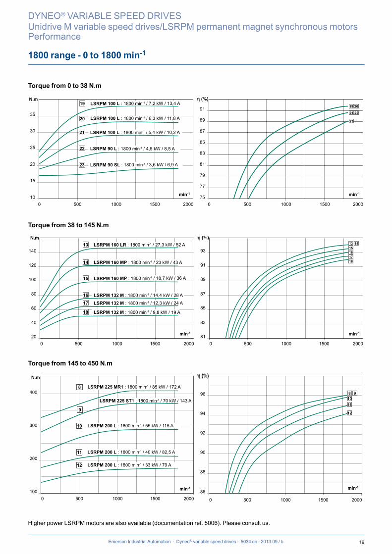
23 LSRPM 90 SL : 1800 min-1 / 3,6 kW / 6,9 A
22 LSRPM 90 L : 1800 min-1 / 4,5 kW / 8,5 A
21 LSRPM 100 L : 1800 min-1 / 5,4 kW / 10,2 A
20 LSRPM 100 L : 1800 min-1 / 6,3 kW / 11,8 A
19 LSRPM 100 L : 1800 min-1 / 7,2 kW / 13,4 A
0 500 1000 1500 2000 0 500 1000 1500 200020
40
60
80
100
120
140
81
83
85
87
89
91
93 161718
151413
18 LSRPM 132 M : 1800 min-1 / 9,8 kW / 19 A
17 LSRPM 132 M : 1800 min-1 / 12,3 kW / 24 A
16 LSRPM 132 M : 1800 min-1 / 14,4 kW / 28 A
15 LSRPM 160 MP : 1800 min-1 / 18,7 kW / 36 A
14 LSRPM 160 MP : 1800 min-1 / 23 kW / 43 A
13 LSRPM 160 LR : 1800 min-1 / 27,3 kW / 52 A
86
88
90
92
94
96
100
200
300
400
0 500 1000 1500 2000 0 500 1000 1500 2000
9
LSRPM 225 ST1 : 1800 min-1 / 70 kW / 143 A
10 LSRPM 200 L : 1800 min-1 / 55 kW / 115 A
11 LSRPM 200 L : 1800 min-1 / 40 kW / 82,5 A
12 LSRPM 200 L : 1800 min-1 / 33 kW / 79 A
8 91011
12
8 LSRPM 225 MR1 : 1800 min-1 / 85 kW / 172 A
Emerson Industrial Automation - Dyneo® variable speed drives - 5034 en - 2013.09 / b
1800 range - 0 to 1800 min-1
DYNEO® VARIABLE SPEED DRIVES
Unidrive M variable speed drives/LSRPM permanent magnet synchronous motorsPerformance
Torque from 0 to 38 N.m
Torque from 38 to 145 N.m
Torque from 145 to 450 N.m
Higher power LSRPM motors are also available (documentation ref. 5006). Please consult us.
20
10
15
20
25
30
35
75
77
79
81
83
85
87
89
91
0 500 1000 1500 0 500 1000 1500
24
20 21
2223
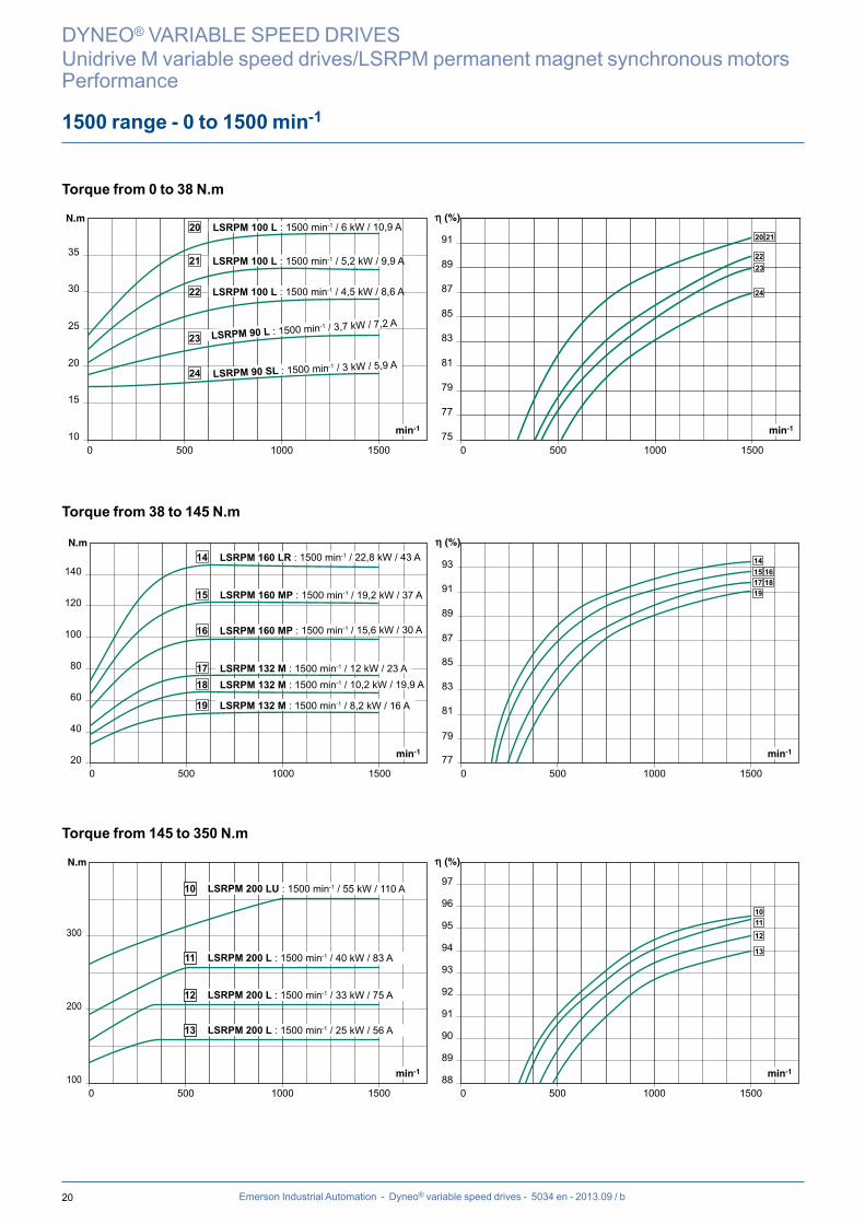
24 LSRPM 90 SL : 1500 min-1 / 3 kW / 5,9 A
23 LSRPM 90 L : 1500 min-1 / 3,7 kW / 7,2 A
22 LSRPM 100 L : 1500 min-1 / 4,5 kW / 8,6 A
21 LSRPM 100 L : 1500 min-1 / 5,2 kW / 9,9 A
20 LSRPM 100 L : 1500 min-1 / 6 kW / 10,9 A
20
40
60
80
100
120
140
77
79
81
83
85
87
89
91
93
0 500 1000 1500 0 500 1000 1500
17 1819
161514
19 LSRPM 132 M : 1500 min-1 / 8,2 kW / 16 A
18 LSRPM 132 M : 1500 min-1 / 10,2 kW / 19,9 A 17 LSRPM 132 M : 1500 min-1 / 12 kW / 23 A
16 LSRPM 160 MP : 1500 min-1 / 15,6 kW / 30 A
15 LSRPM 160 MP : 1500 min-1 / 19,2 kW / 37 A
14 LSRPM 160 LR : 1500 min-1 / 22,8 kW / 43 A
88
89
90
91
92
93
94
95
96
97
100
200
300
0 500 1000 1500 0 500 1000 1500
10 LSRPM 200 LU : 1500 min-1 / 55 kW / 110 A
11 LSRPM 200 L : 1500 min-1 / 40 kW / 83 A
12 LSRPM 200 L : 1500 min-1 / 33 kW / 75 A
13 LSRPM 200 L : 1500 min-1 / 25 kW / 56 A
1011
12
13
Emerson Industrial Automation - Dyneo® variable speed drives - 5034 en - 2013.09 / b
1500 range - 0 to 1500 min-1
DYNEO® VARIABLE SPEED DRIVES
Unidrive M variable speed drives/LSRPM permanent magnet synchronous motorsPerformance
Torque from 0 to 38 N.m
Torque from 38 to 145 N.m
Torque from 145 to 350 N.m

21
88
89
90
91
92
93
94
95
96
97
400
300
500
600
700
800
0 500 1000 1500 0 500 1000 1500
8 LSRPM 250 ME : 1500 min-1 / 85 kW / 175 A
9 LSRPM 225 MR1 : 1500 min-1 / 70 kW / 142 A
98
Emerson Industrial Automation - Dyneo® variable speed drives - 5034 en - 2013.09 / b
1500 range - 0 to 1500 min-1
DYNEO® VARIABLE SPEED DRIVES
Unidrive M variable speed drives/LSRPM permanent magnet synchronous motorsPerformance
Torque from 350 to 550 N.m
Higher power LSRPM motors are also available (documentation ref. 5006). Please consult us.
22
100
200
300
80
82
84
86
88
90
92
0 800600400200 1000 0 800600400200 1000
8 LSRPM 200 LU : 900 min-1 / 33 kW / 70 A
9 LSRPM 200 L : 900 min-1 / 25 kW / 52 A
10 LSRPM 200 L : 900 min-1 / 20 kW / 43 A
11 LSRPM 200 L : 900 min-1 / 15 kW / 38 A
89
10
11
0 800600400200 1000 0 800600400200 100010
15
20
25
30
35
60
65
70
75
80
85
22
18192021
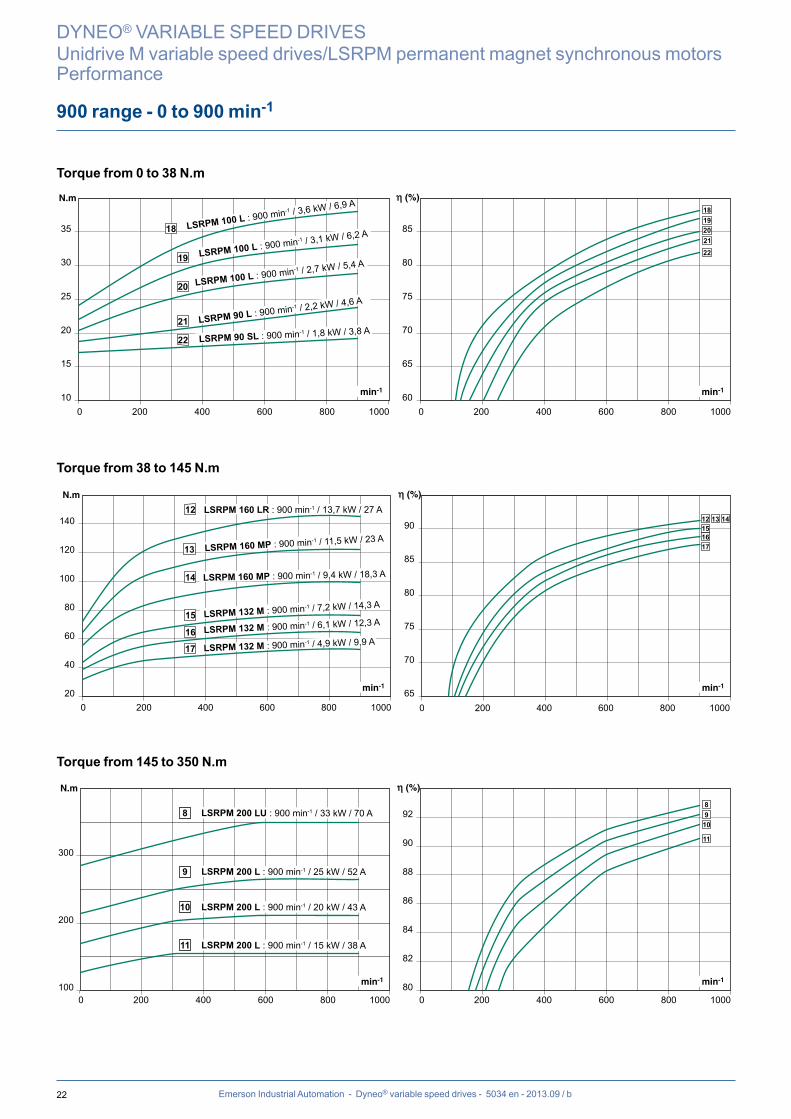
22 LSRPM 90 SL : 900 min-1 / 1,8 kW / 3,8 A 21 LSRPM 90 L : 900 min-1 / 2,2 kW / 4,6 A 20 LSRPM 100 L : 900 min-1 / 2,7 kW / 5,4 A 19 LSRPM 100 L : 900 min-1 / 3,1 kW / 6,2 A 18 LSRPM 100 L : 900 min-1 / 3,6 kW / 6,9 A
0 200 400 600 800 1000 0 200 400 600 800 100020
40
60
80
100
120
140
65
70
75
80
85
90 151617
12 13 14
17 LSRPM 132 M : 900 min-1 / 4,9 kW / 9,9 A 16 LSRPM 132 M : 900 min-1 / 6,1 kW / 12,3 A 15 LSRPM 132 M : 900 min-1 / 7,2 kW / 14,3 A
14 LSRPM 160 MP : 900 min-1 / 9,4 kW / 18,3 A
13 LSRPM 160 MP : 900 min-1 / 11,5 kW / 23 A
12 LSRPM 160 LR : 900 min-1 / 13,7 kW / 27 A
Emerson Industrial Automation - Dyneo® variable speed drives - 5034 en - 2013.09 / b
900 range - 0 to 900 min-1
DYNEO® VARIABLE SPEED DRIVES
Unidrive M variable speed drives/LSRPM permanent magnet synchronous motorsPerformance
Torque from 0 to 38 N.m
Torque from 38 to 145 N.m
Torque from 145 to 350 N.m
23
400
500
600
700
800
88
89
90
91
92
93
94
95
96
0 800600400200 1000 0 800600400200 1000
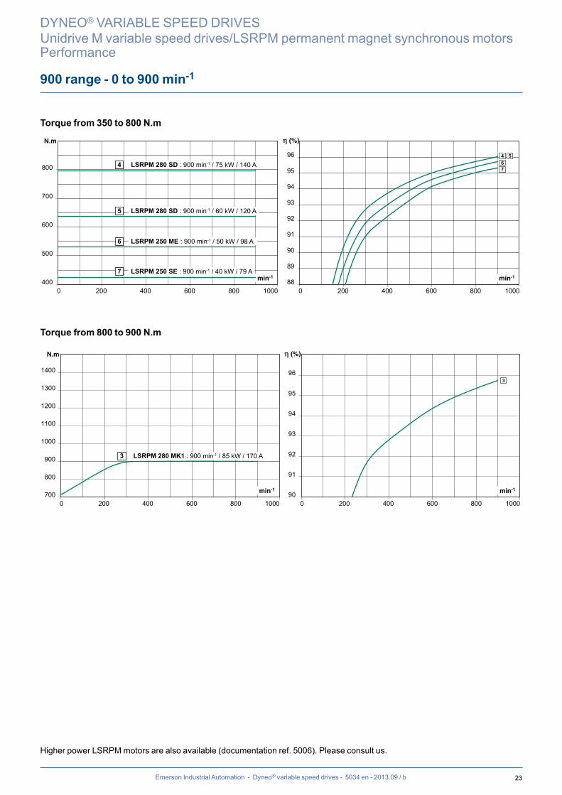
4 LSRPM 280 SD : 900 min-1 / 75 kW / 140 A
5 LSRPM 280 SD : 900 min-1 / 60 kW / 120 A
6 LSRPM 250 ME : 900 min-1 / 50 kW / 98 A
7 LSRPM 250 SE : 900 min-1 / 40 kW / 79 A
4 567
700
800
900
1000
1100
1200
1300
1400
90
91
92
93
94
95
96
0 800600400200 1000 0 800600400200 1000
3 LSRPM 280 MK1 : 900 min-1 / 85 kW / 170 A
3
Emerson Industrial Automation - Dyneo® variable speed drives - 5034 en - 2013.09 / b
900 range - 0 to 900 min-1
DYNEO® VARIABLE SPEED DRIVES
Unidrive M variable speed drives/LSRPM permanent magnet synchronous motorsPerformance
Torque from 350 to 800 N.m
Torque from 800 to 900 N.m
Higher power LSRPM motors are also available (documentation ref. 5006). Please consult us.
24
10
15
20
25
30
35
60
65
70
75
80
85
0 100 200 300 400 500 600 700 8000 100 200 300 400 500 600 700 800
17181920
21
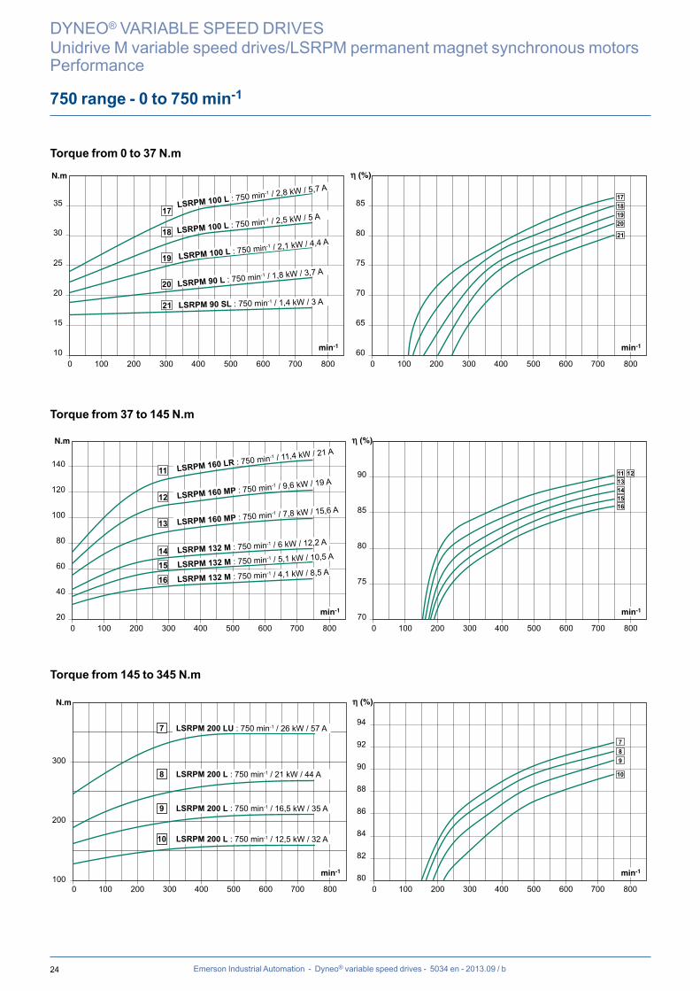
17LSRPM 100 L : 750 min-1 / 2,8 kW / 5,7 A
21 LSRPM 90 SL : 750 min-1 / 1,4 kW / 3 A
20 LSRPM 90 L : 750 min-1 / 1,8 kW / 3,7 A 19 LSRPM 100 L : 750 min-1 / 2,1 kW / 4,4 A 18 LSRPM 100 L : 750 min-1 / 2,5 kW / 5 A
20
40
60
80
100
120
140
70
75
80
85
90
0 100 200 300 400 500 600 700 8000 100 200 300 400 500 600 700 800
1516
1413
1211
16 LSRPM 132 M : 750 min-1 / 4,1 kW / 8,5 A 15 LSRPM 132 M : 750 min-1 / 5,1 kW / 10,5 A 14 LSRPM 132 M : 750 min-1 / 6 kW / 12,2 A
13 LSRPM 160 MP : 750 min-1 / 7,8 kW / 15,6 A 12 LSRPM 160 MP : 750 min-1 / 9,6 kW / 19 A 11 LSRPM 160 LR : 750 min-1 / 11,4 kW / 21 A
100
200
300
80
82
84
86
88
90
92
94
0 100 200 300 400 500 600 700 8000 100 200 300 400 500 600 700 800
10 LSRPM 200 L : 750 min-1 / 12,5 kW / 32 A
9 LSRPM 200 L : 750 min-1 / 16,5 kW / 35 A
8 LSRPM 200 L : 750 min-1 / 21 kW / 44 A
7 LSRPM 200 LU : 750 min-1 / 26 kW / 57 A
89
10
7
Emerson Industrial Automation - Dyneo® variable speed drives - 5034 en - 2013.09 / b
750 range - 0 to 750 min-1
DYNEO® VARIABLE SPEED DRIVES
Unidrive M variable speed drives/LSRPM permanent magnet synchronous motorsPerformance
Torque from 0 to 37 N.m
Torque from 37 to 145 N.m
Torque from 145 to 345 N.m
25
300
400
500
600
700
800
900
88
89
90
91
92
93
94
95
96
0 100 200 300 400 500 600 700 8000 100 200 300 400 500 600 700 800
3
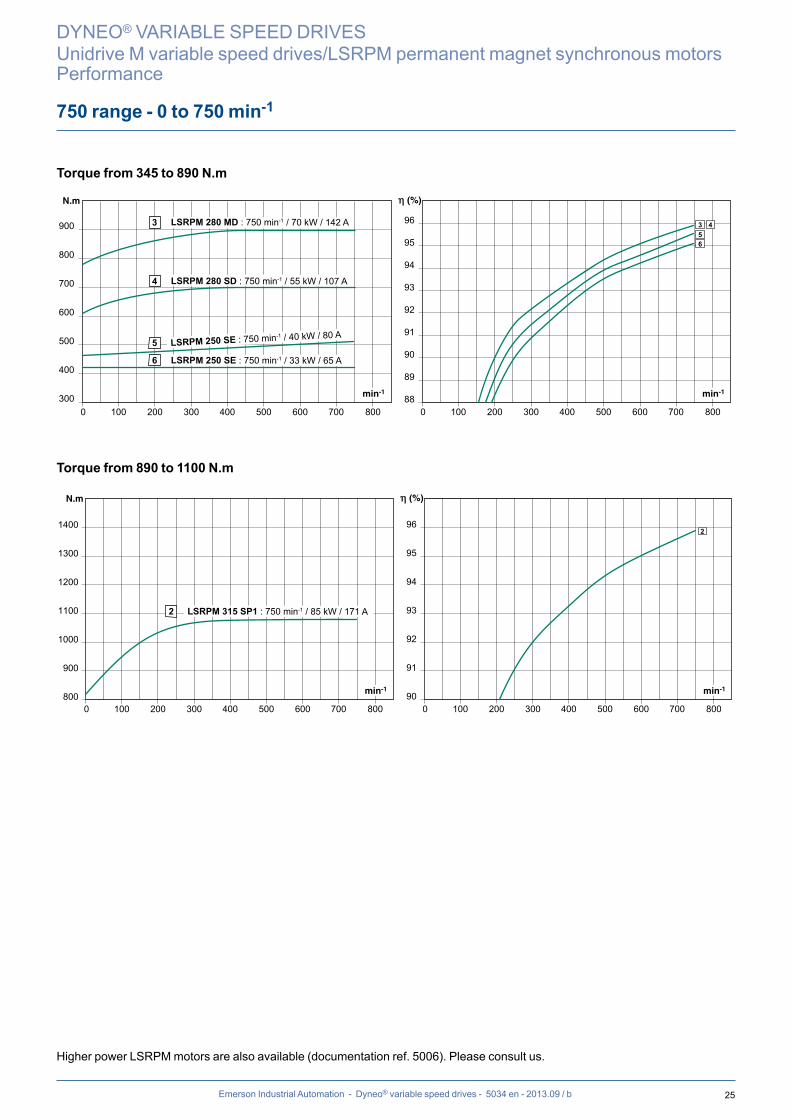
5 LSRPM 250 SE : 750 min-1 / 40 kW / 80 A
6 LSRPM 250 SE : 750 min-1 / 33 kW / 65 A
LSRPM 280 MD : 750 min-1 / 70 kW / 142 A
4 LSRPM 280 SD : 750 min-1 / 55 kW / 107 A
543
6
800
900
1000
1100
1200
1300
1400
90
91
92
93
94
95
96
0 100 200 300 400 500 600 700 8000 100 200 300 400 500 600 700 800
2 LSRPM 315 SP1 : 750 min-1 / 85 kW / 171 A
2
Emerson Industrial Automation - Dyneo® variable speed drives - 5034 en - 2013.09 / b
750 range - 0 to 750 min-1
DYNEO® VARIABLE SPEED DRIVES
Unidrive M variable speed drives/LSRPM permanent magnet synchronous motorsPerformance
Torque from 345 to 890 N.m
Torque from 890 to 1100 N.m
Higher power LSRPM motors are also available (documentation ref. 5006). Please consult us.
26 Emerson Industrial Automation - Dyneo® variable speed drives - 5034 en - 2013.09 / b
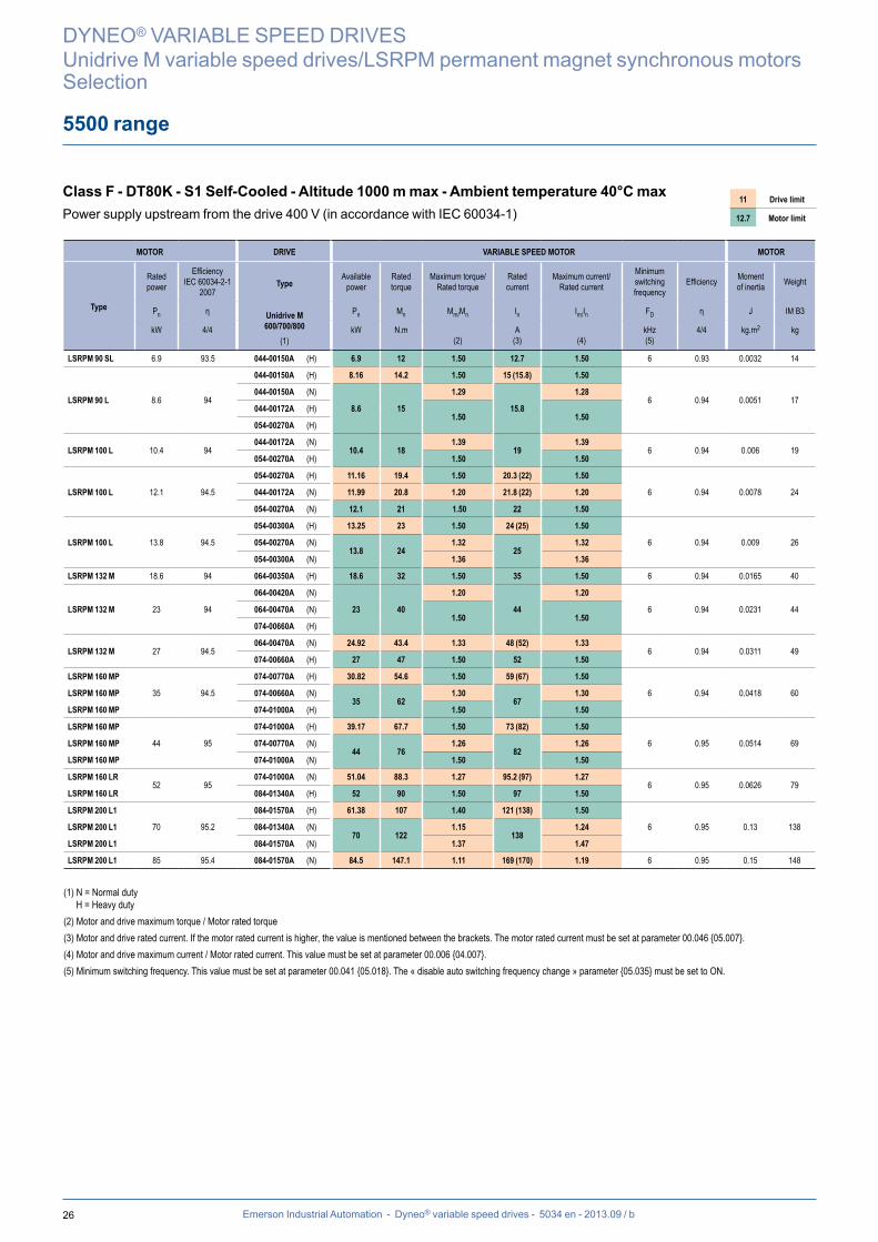
5500 range
Class F - DT80K - S1 Self-Cooled - Altitude 1000 m max - Ambient temperature 40°C maxPower supply upstream from the drive 400 V (in accordance with IEC 60034-1)
11 Drive limit
12.7 Motor limit
DYNEO® VARIABLE SPEED DRIVES
Unidrive M variable speed drives/LSRPM permanent magnet synchronous motorsSelection
MOTOR DRIVE VARIABLE SPEED MOTOR MOTOR
Type
Rated power
Efficiency IEC 60034-2-1
2007
Type
Unidrive M600/700/800
(1)
Available power
Rated torque
Maximum torque/ Rated torque
Rated current
Maximum current/ Rated current
Minimum switching frequency
Efficiency Moment of inertia Weight
Pn η Pn Mn Mm/Mn In Im/In FD η J IM B3
kW 4/4 kW N.m(2)
A(3) (4)
kHz(5)
4/4 kg.m2 kg
LSRPM 90 SL 6.9 93.5 044-00150A (H) 6.9 12 1.50 12.7 1.50 6 0.93 0.0032 14
LSRPM 90 L 8.6 94
044-00150A (H) 8.16 14.2 1.50 15 (15.8) 1.50
6 0.94 0.0051 17044-00150A (N)
8.6 15
1.29
15.8
1.28
044-00172A (H) 1.50 1.50
054-00270A (H)
LSRPM 100 L 10.4 94044-00172A (N)
10.4 18 1.39
191.39
6 0.94 0.006 19054-00270A (H) 1.50 1.50
12.1 94.5
054-00270A (H) 11.16 19.4 1.50 20.3 (22) 1.50
6 0.94 0.0078 24LSRPM 100 L 044-00172A (N) 11.99 20.8 1.20 21.8 (22) 1.20
054-00270A (N) 12.1 21 1.50 22 1.50
LSRPM 100 L 13.8 94.5
054-00300A (H) 13.25 23 1.50 24 (25) 1.50
6 0.94 0.009 26054-00270A (N)13.8 24
1.32 25
1.32
054-00300A (N) 1.36 1.36
LSRPM 132 M 18.6 94 064-00350A (H) 18.6 32 1.50 35 1.50 6 0.94 0.0165 40
LSRPM 132 M 23 94
064-00420A (N)
23 40
1.20
44
1.20
6 0.94 0.0231 44064-00470A (N) 1.50 1.50
074-00660A (H)
LSRPM 132 M 27 94.5064-00470A (N) 24.92 43.4 1.33 48 (52) 1.33
6 0.94 0.0311 49074-00660A (H) 27 47 1.50 52 1.50
LSRPM 160 MP
35 94.5
074-00770A (H) 30.82 54.6 1.50 59 (67) 1.50
6 0.94 0.0418 60LSRPM 160 MP 074-00660A (N)35 62
1.30 67
1.30
LSRPM 160 MP 074-01000A (H) 1.50 1.50
LSRPM 160 MP
44 95
074-01000A (H) 39.17 67.7 1.50 73 (82) 1.50
6 0.95 0.0514 69LSRPM 160 MP 074-00770A (N)44 76
1.26 82
1.26
LSRPM 160 MP 074-01000A (N) 1.50 1.50
LSRPM 160 LR52 95
074-01000A (N) 51.04 88.3 1.27 95.2 (97) 1.27 6 0.95 0.0626 79
LSRPM 160 LR 084-01340A (H) 52 90 1.50 97 1.50
LSRPM 200 L1
70 95.2
084-01570A (H) 61.38 107 1.40 121 (138) 1.50
6 0.95 0.13 138LSRPM 200 L1 084-01340A (N)70 122
1.15 138
1.24
LSRPM 200 L1 084-01570A (N) 1.37 1.47
LSRPM 200 L1 85 95.4 084-01570A (N) 84.5 147.1 1.11 169 (170) 1.19 6 0.95 0.15 148
(1) N = Normal dutyH = Heavy duty
(2) Motor and drive maximum torque / Motor rated torque(3) Motor and drive rated current. If the motor rated current is higher, the value is mentioned between the brackets. The motor rated current must be set at parameter 00.046 {05.007}.(4) Motor and drive maximum current / Motor rated current. This value must be set at parameter 00.006 {04.007}.(5) Minimum switching frequency. This value must be set at parameter 00.041 {05.018}. The « disable auto switching frequency change » parameter {05.035} must be set to ON.
27Emerson Industrial Automation - Dyneo® variable speed drives - 5034 en - 2013.09 / b
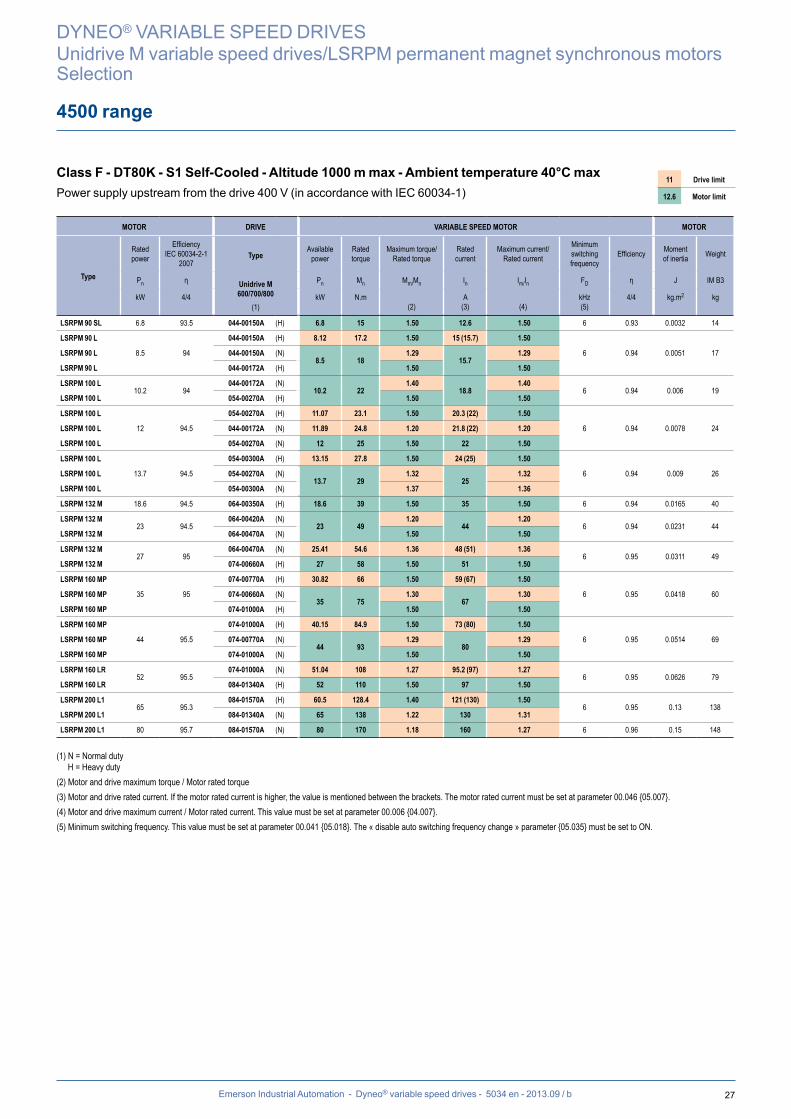
4500 range
Class F - DT80K - S1 Self-Cooled - Altitude 1000 m max - Ambient temperature 40°C maxPower supply upstream from the drive 400 V (in accordance with IEC 60034-1)
11 Drive limit
12.6 Motor limit
DYNEO® VARIABLE SPEED DRIVES
Unidrive M variable speed drives/LSRPM permanent magnet synchronous motorsSelection
(1) N = Normal dutyH = Heavy duty
(2) Motor and drive maximum torque / Motor rated torque(3) Motor and drive rated current. If the motor rated current is higher, the value is mentioned between the brackets. The motor rated current must be set at parameter 00.046 {05.007}.(4) Motor and drive maximum current / Motor rated current. This value must be set at parameter 00.006 {04.007}.(5) Minimum switching frequency. This value must be set at parameter 00.041 {05.018}. The « disable auto switching frequency change » parameter {05.035} must be set to ON.
MOTOR DRIVE VARIABLE SPEED MOTOR MOTOR
Type
Rated power
Efficiency IEC 60034-2-1
2007
Type
Unidrive M600/700/800
(1)
Available power
Rated torque
Maximum torque/ Rated torque
Rated current
Maximum current/ Rated current
Minimum switching frequency
Efficiency Moment of inertia Weight
Pn η Pn Mn Mm/Mn In Im/In FD η J IM B3
kW 4/4 kW N.m(2)
A(3) (4)
kHz(5)
4/4 kg.m2 kg
LSRPM 90 SL 6.8 93.5 044-00150A (H) 6.8 15 1.50 12.6 1.50 6 0.93 0.0032 14
LSRPM 90 L
8.5 94
044-00150A (H) 8.12 17.2 1.50 15 (15.7) 1.50
6 0.94 0.0051 17LSRPM 90 L 044-00150A (N)8.5 18
1.29 15.7
1.29
LSRPM 90 L 044-00172A (H) 1.50 1.50
LSRPM 100 L10.2 94
044-00172A (N)10.2 22
1.40 18.8
1.40 6 0.94 0.006 19
LSRPM 100 L 054-00270A (H) 1.50 1.50
LSRPM 100 L
12 94.5
054-00270A (H) 11.07 23.1 1.50 20.3 (22) 1.50
6 0.94 0.0078 24LSRPM 100 L 044-00172A (N) 11.89 24.8 1.20 21.8 (22) 1.20
LSRPM 100 L 054-00270A (N) 12 25 1.50 22 1.50
LSRPM 100 L
13.7 94.5
054-00300A (H) 13.15 27.8 1.50 24 (25) 1.50
6 0.94 0.009 26LSRPM 100 L 054-00270A (N)13.7 29
1.32 25
1.32
LSRPM 100 L 054-00300A (N) 1.37 1.36
LSRPM 132 M 18.6 94.5 064-00350A (H) 18.6 39 1.50 35 1.50 6 0.94 0.0165 40
LSRPM 132 M23 94.5
064-00420A (N)23 49
1.20 44
1.20 6 0.94 0.0231 44
LSRPM 132 M 064-00470A (N) 1.50 1.50
LSRPM 132 M27 95
064-00470A (N) 25.41 54.6 1.36 48 (51) 1.36 6 0.95 0.0311 49
LSRPM 132 M 074-00660A (H) 27 58 1.50 51 1.50
LSRPM 160 MP
35 95
074-00770A (H) 30.82 66 1.50 59 (67) 1.50
6 0.95 0.0418 60LSRPM 160 MP 074-00660A (N)35 75
1.30 67
1.30
LSRPM 160 MP 074-01000A (H) 1.50 1.50
LSRPM 160 MP
44 95.5
074-01000A (H) 40.15 84.9 1.50 73 (80) 1.50
6 0.95 0.0514 69LSRPM 160 MP 074-00770A (N)44 93
1.29 80
1.29
LSRPM 160 MP 074-01000A (N) 1.50 1.50
LSRPM 160 LR52 95.5
074-01000A (N) 51.04 108 1.27 95.2 (97) 1.27 6 0.95 0.0626 79
LSRPM 160 LR 084-01340A (H) 52 110 1.50 97 1.50
LSRPM 200 L165 95.3
084-01570A (H) 60.5 128.4 1.40 121 (130) 1.50 6 0.95 0.13 138
LSRPM 200 L1 084-01340A (N) 65 138 1.22 130 1.31
LSRPM 200 L1 80 95.7 084-01570A (N) 80 170 1.18 160 1.27 6 0.96 0.15 148
28 Emerson Industrial Automation - Dyneo® variable speed drives - 5034 en - 2013.09 / b
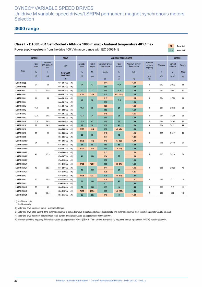
3600 range
Class F - DT80K - S1 Self-Cooled - Altitude 1000 m max - Ambient temperature 40°C maxPower supply upstream from the drive 400 V (in accordance with IEC 60034-1)
11 Drive limit
11.9 Motor limit
DYNEO® VARIABLE SPEED DRIVES
Unidrive M variable speed drives/LSRPM permanent magnet synchronous motorsSelection
MOTOR DRIVE VARIABLE SPEED MOTOR MOTOR
Type
Rated power
Efficiency IEC 60034-2-1
2007
Type
Unidrive M600/700/800
(1)
Available power
Rated torque
Maximum torque/ Rated torque
Rated current
Maximum current/ Rated current
Minimum switching frequency
Efficiency Moment of inertia Weight
Pn η Pn Mn Mm/Mn In Im/In FD η J IM B3
kW 4/4 kW N.m(2)
A(3) (4)
kHz(5)
4/4 kg.m2 kg
LSRPM 90 SL6.4 93
034-00100A (N)6.4 17
1.14 11.9
1.13 4 0.93 0.0032 14
LSRPM 90 SL 044-00150A (H) 1.50 1.50
LSRPM 90 L 8 93.5 044-00150A (H) 8 21 1.50 14.8 1.50 4 0.93 0.0051 17
LSRPM 100 L
9.6 94
044-00172A (H) 9.38 25.4 1.50 17.2 (17.6) 1.50
4 0.94 0.006 19LSRPM 100 L 044-00150A (N)9.6 26
1.15 17.6
1.15
LSRPM 100 L 044-00172A (N) 1.50 1.50
LSRPM 100 L11.2 94
044-00172A (N)11.2 30
1.26 21
1.26 4 0.94 0.0078 24
LSRPM 100 L 054-00270A (H) 1.50 1.50
LSRPM 100 L12.8 94.5
044-00172A (N)12.8 34
1.15 23
1.15 4 0.94 0.009 26
LSRPM 100 L 054-00270A (H) 1.50 1.50
LSRPM 132 M 17.6 94.5 064-00350A (H) 17.6 47 1.50 33 1.50 4 0.94 0.0165 40
LSRPM 132 M 22 94.5 064-00420A (H) 22 58 1.50 41 1.50 4 0.94 0.0231 44
LSRPM 132 M
26 95
064-00420A (H) 22.75 60.4 1.50 42 (48) 1.50
4 0.95 0.0311 49LSRPM 132 M 064-00420A (N)26 69
1.10 48
1.10
LSRPM 132 M 064-00470A (N) 1.44 1.44
LSRPM 160 MP34 95
064-00470A (N) 30.76 80.5 1.10 57 (63) 1.10 4 0.95 0.0418 60
LSRPM 160 MP 074-00660A (H) 34 89 1.50 63 1.50
LSRPM 160 MP
41 95.5
074-00770A (H) 37.27 99.1 1.50 70 (77) 1.50
4 0.95 0.0514 69LSRPM 160 MP 074-00660A (N)
41 109
1.13
77
1.13
LSRPM 160 MP 074-00770A (N) 1.34 1.34
LSRPM 160 MP 074-01000A (H) 1.50 1.50
LSRPM 160 LR
49 95.5
074-01000A (H) 47.38 125.7 1.50 88 (91) 1.50
4 0.95 0.0626 79LSRPM 160 LR 074-00770A (N)49 130
1.14 91
1.14
LSRPM 160 LR 074-01000A (N) 1.35 1.35
LSRPM 200 L
50 95.5
074-01000A (H) 45.36 120.7 1.35 88 (97) 1.45
4 0.95 0.13 135LSRPM 200 L 074-01000A (N)50 133
1.18 97
1.27
LSRPM 200 L 074-01340A (N) 1.35 1.45
LSRPM 200 L1 70 96 084-01340A (H) 70 186 1.35 130 1.45 4 0.96 0.17 153
LSRPM 200 L185 96.4
084-01570A (H) 76.93 203.6 1.35 143 (158) 1.45 4 0.96 0.22 178
LSRPM 200 L1 084-01570A (N) 85 225 1.19 158 1.28
(1) N = Normal dutyH = Heavy duty
(2) Motor and drive maximum torque / Motor rated torque(3) Motor and drive rated current. If the motor rated current is higher, the value is mentioned between the brackets. The motor rated current must be set at parameter 00.046 {05.007}.(4) Motor and drive maximum current / Motor rated current. This value must be set at parameter 00.006 {04.007}.(5) Minimum switching frequency. This value must be set at parameter 00.041 {05.018}. The « disable auto switching frequency change » parameter {05.035} must be set to ON.

29Emerson Industrial Automation - Dyneo® variable speed drives - 5034 en - 2013.09 / b
3000 range
Class F - DT80K - S1 Self-Cooled - Altitude 1000 m max - Ambient temperature 40°C maxPower supply upstream from the drive 400 V (in accordance with IEC 60034-1)
15.3 Drive limit
16.2 Motor limit
DYNEO® VARIABLE SPEED DRIVES
Unidrive M variable speed drives/LSRPM permanent magnet synchronous motorsSelection
MOTOR DRIVE VARIABLE SPEED MOTOR MOTOR
Type
Rated power
Efficiency IEC 60034-2-1
2007
Type
Unidrive M600/700/800
(1)
Available power
Rated torque
Maximum torque/ Rated torque
Rated current
Maximum current/ Rated current
Minimum switching frequency
Efficiency Moment of inertia Weight
Pn η Pn Mn Mm/Mn In Im/In FD η J IM B3
kW 4/4 kW N.m(2)
A(3) (4)
kHz(5)
4/4 kg.m2 kg
LSRPM 90 SL 5.8 91.5 034-00100A (N) 5.8 19 1.23 11 1.23 4 0.91 0.0032 14
LSRPM 90 L 7.3 93 044-00150A (H) 7.3 23 1.50 13.5 1.50 4 0.93 0.0051 17
LSRPM 100 L
8.7 93
044-00150A (H) 8.06 25.9 1.50 15 (16.2) 1.50
4 0.93 0.006 19LSRPM 100 L 044-00150A (N)8.7 28
1.25 16.2
1.25
LSRPM 100 L 044-00172A (H) 1.50 1.50
LSRPM 100 L
10.2 93.5
044-00172A (H) 9.33 29.3 1.50 17.2 (18.8) 1.50
4 0.93 0.0078 24LSRPM 100 L 044-00172A (N)10.2 32
1.40 18.8
1.40
LSRPM 100 L 054-00270A (H) 1.50 1.50
LSRPM 100 L11.6 93.5
044-00172A (N)11.6 37
1.26 21
1.26 4 0.93 0.009 26
LSRPM 100 L 054-00270A (H) 1.50 1.50
LSRPM 132 M
15.8 93
054-00300A (H) 14.69 46.5 1.50 27.9 (30) 1.50
4 0.93 0.0165 40LSRPM 132 M 054-00270A (N)
15.8 50
1.10
30
1.10
LSRPM 132 M 054-00300A (N) 1.14 1.14
LSRPM 132 M 064-00350A (H) 1.50 1.50
LSRPM 132 M
19.7 93.5
064-00350A (H) 18.14 58 1.50 35 (38) 1.50
4 0.93 0.0231 44LSRPM 132 M 064-00350A (N)19.7 63
1.10 38
1.10
LSRPM 132 M 064-00420A (H) 1.50 1.50
LSRPM 132 M
23 94
064-00420A (H)21.95 70.6 1.50 42 (44) 1.50
4 0.94 0.0311 49LSRPM 132 M 064-00470A (H)
LSRPM 132 M 064-00420A (N)23 74
1.20 44
1.20
LSRPM 132 M 064-00470A (N) 1.50 1.50
LSRPM 160 MP30 94.5
064-00470A (N)30 96
1.22 57
1.22 4 0.94 0.0418 60
LSRPM 160 MP 074-00660A (H) 1.50 1.50
LSRPM 160 MP
37 95
074-00660A (H) 35.91 114.5 1.50 66 (68) 1.50
4 0.95 0.0514 69LSRPM 160 MP 074-00660A (N)37 118
1.28 68
1.28
LSRPM 160 MP 074-00770A (H) 1.50 1.50
LSRPM 160 LR44 95
074-00770A (N)44 140
1.26 82
1.26 4 0.95 0.0626 79
LSRPM 160 LR 074-01000A (H) 1.50 1.50
LSRPM 200 L 50 95.5 084-01340A (H) 50 159 1.35 112 1.45 4 0.95 0.13 135
LSRPM 200 L1 65 96 084-01340A (H) 65 207 1.35 126 1.45 4 0.96 0.17 153
LSRPM 200 L1 85 96.5 084-01570A (N) 85 271 1.11 170 1.19 4 0.96 0.22 178
(1) N = Normal dutyH = Heavy duty
(2) Motor and drive maximum torque / Motor rated torque(3) Motor and drive rated current. If the motor rated current is higher, the value is mentioned between the brackets. The motor rated current must be set at parameter 00.046 {05.007}.(4) Motor and drive maximum current / Motor rated current. This value must be set at parameter 00.006 {04.007}.(5) Minimum switching frequency. This value must be set at parameter 00.041 {05.018}. The « disable auto switching frequency change » parameter {05.035} must be set to ON.
30 Emerson Industrial Automation - Dyneo® variable speed drives - 5034 en - 2013.09 / b
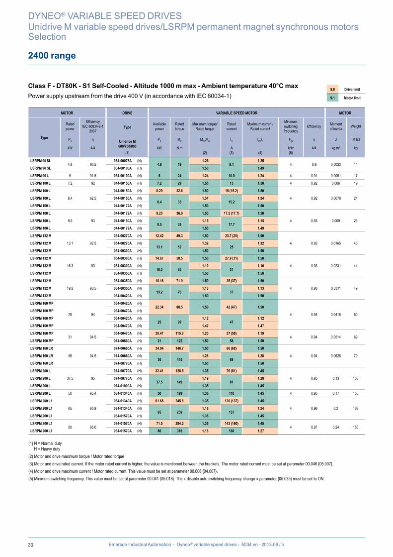
2400 range
Class F - DT80K - S1 Self-Cooled - Altitude 1000 m max - Ambient temperature 40°C maxPower supply upstream from the drive 400 V (in accordance with IEC 60034-1)
8.8 Drive limit
9.1 Motor limit
DYNEO® VARIABLE SPEED DRIVES
Unidrive M variable speed drives/LSRPM permanent magnet synchronous motorsSelection
MOTOR DRIVE VARIABLE SPEED MOTOR MOTOR
Type
Rated power
Efficiency IEC 60034-2-1
2007
Type
Unidrive M600/700/800
(1)
Available power
Rated torque
Maximum torque/ Rated torque
Rated current
Maximum current/ Rated current
Minimum switching frequency
Efficiency Moment of inertia Weight
Pn η Pn Mn Mm/Mn In Im/In FD η J IM B3
kW 4/4 kW N.m(2)
A(3) (4)
kHz(5)
4/4 kg.m2 kg
LSRPM 90 SL4.8 90.5
034-00078A (N)4.8 19
1.26 9.1
1.25 4 0.9 0.0032 14
LSRPM 90 SL 034-00100A (H) 1.50 1.49
LSRPM 90 L 6 91.5 034-00100A (N) 6 24 1.24 10.9 1.24 4 0.91 0.0051 17
LSRPM 100 L 7.2 92 044-00150A (H) 7.2 29 1.50 13 1.50 4 0.92 0.006 19
LSRPM 100 L
8.4 92.5
044-00150A (H) 8.29 32.6 1.50 15 (15.2) 1.50
4 0.92 0.0078 24LSRPM 100 L 044-00150A (N)8.4 33
1.34 15.2
1.34
LSRPM 100 L 044-00172A (H) 1.50 1.50
LSRPM 100 L
9.5 93
044-00172A (H) 9.23 36.9 1.50 17.2 (17.7) 1.50
4 0.93 0.009 26LSRPM 100 L 044-00150A (N)9.5 38
1.15 17.7
1.15
LSRPM 100 L 044-00172A (N) 1.50 1.49
LSRPM 132 M
13.1 92.5
054-00270A (H) 12.42 49.3 1.50 23.7 (25) 1.50
4 0.92 0.0165 40LSRPM 132 M 054-00270A (N)13.1 52
1.32 25
1.32
LSRPM 132 M 054-00300A (H) 1.50 1.50
LSRPM 132 M
16.3 93
054-00300A (H) 14.67 58.5 1.50 27.9 (31) 1.50
4 0.93 0.0231 44LSRPM 132 M 054-00300A (N)16.3 65
1.10 31
1.10
LSRPM 132 M 064-00350A (H) 1.50 1.50
LSRPM 132 M
19.2 93.5
064-00350A (H) 18.16 71.9 1.50 35 (37) 1.50
4 0.93 0.0311 49LSRPM 132 M 064-00350A (N)19.2 76
1.13 37
1.13
LSRPM 132 M 064-00420A (H) 1.50 1.50
LSRPM 160 MP
25 94
064-00420A (H)22.34 88.5 1.50 42 (47) 1.50
4 0.94 0.0418 60LSRPM 160 MP 064-00470A (H)
LSRPM 160 MP 064-00420A (N)25 99
1.12 47
1.12
LSRPM 160 MP 064-00470A (N) 1.47 1.47
LSRPM 160 MP31 94.5
064-00470A (N) 30.47 119.9 1.20 57 (58) 1.19 4 0.94 0.0514 69
LSRPM 160 MP 074-00660A (H) 31 122 1.50 58 1.50
LSRPM 160 LR
36 94.5
074-00660A (H) 34.94 140.7 1.50 66 (68) 1.50
4 0.94 0.0626 79LSRPM 160 LR 074-00660A (N)36 145
1.28 68
1.28
LSRPM 160 LR 074-00770A (H) 1.50 1.50
LSRPM 200 L
37.5 95
074-00770A (H) 32.41 128.8 1.35 70 (81) 1.45
4 0.95 0.13 135LSRPM 200 L 074-00770A (N)37.5 149
1.19 81
1.28
LSRPM 200 L 074-01000A (H) 1.35 1.45
LSRPM 200 L 50 95.4 084-01340A (H) 50 199 1.35 110 1.45 4 0.95 0.17 150
LSRPM 200 L1
65 95.9
084-01340A (H) 61.68 245.8 1.35 130 (137) 1.45
4 0.96 0.2 168LSRPM 200 L1 084-01340A (N)65 259
1.16 137
1.24
LSRPM 200 L1 084-01570A (H) 1.35 1.45
LSRPM 200 L180 96.6
084-01570A (H) 71.5 284.2 1.35 143 (160) 1.45 4 0.97 0.24 183
LSRPM 200 L1 084-01570A (N) 80 318 1.18 160 1.27
(1) N = Normal dutyH = Heavy duty
(2) Motor and drive maximum torque / Motor rated torque(3) Motor and drive rated current. If the motor rated current is higher, the value is mentioned between the brackets. The motor rated current must be set at parameter 00.046 {05.007}.(4) Motor and drive maximum current / Motor rated current. This value must be set at parameter 00.006 {04.007}.(5) Minimum switching frequency. This value must be set at parameter 00.041 {05.018}. The « disable auto switching frequency change » parameter {05.035} must be set to ON.
31Emerson Industrial Automation - Dyneo® variable speed drives - 5034 en - 2013.09 / b
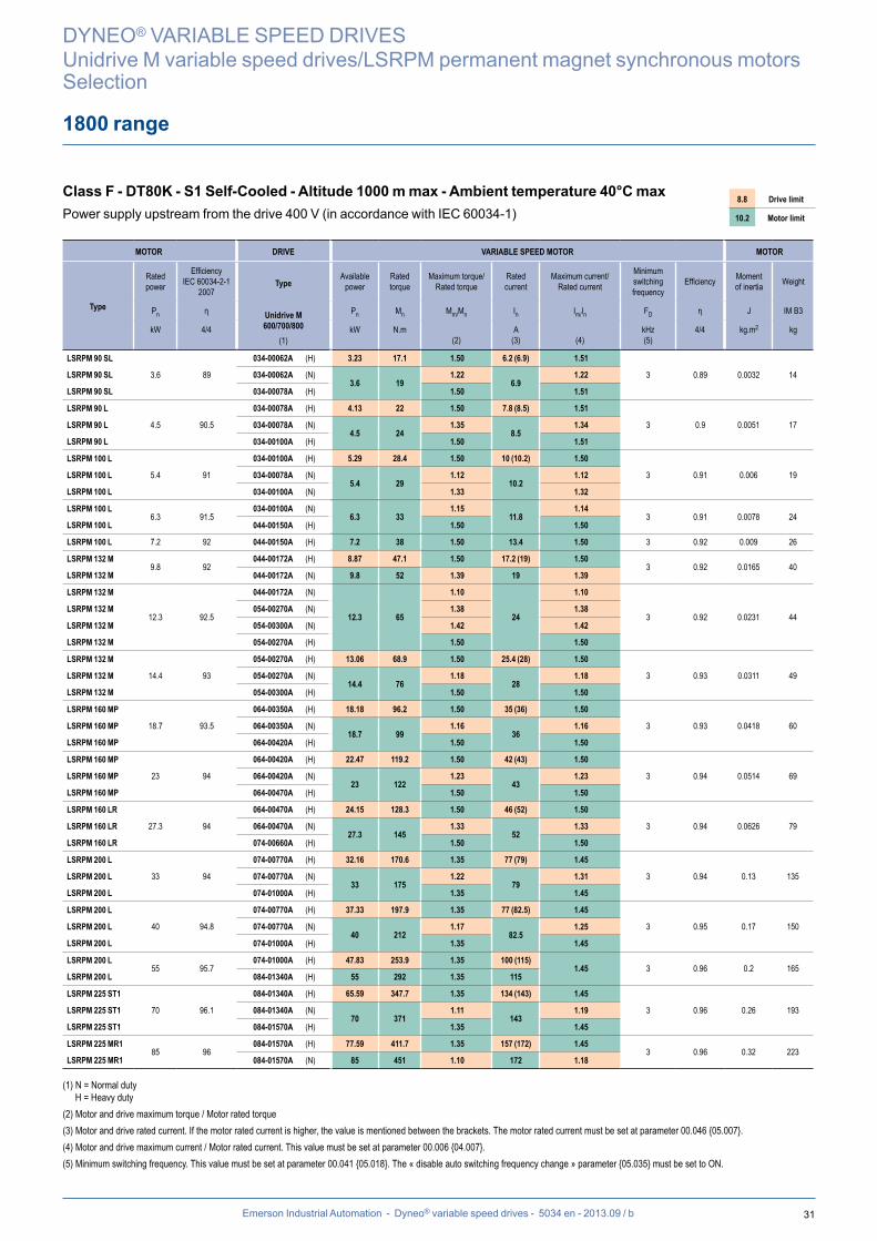
1800 range
Class F - DT80K - S1 Self-Cooled - Altitude 1000 m max - Ambient temperature 40°C maxPower supply upstream from the drive 400 V (in accordance with IEC 60034-1)
8.8 Drive limit
10.2 Motor limit
DYNEO® VARIABLE SPEED DRIVES
Unidrive M variable speed drives/LSRPM permanent magnet synchronous motorsSelection
MOTOR DRIVE VARIABLE SPEED MOTOR MOTOR
Type
Rated power
Efficiency IEC 60034-2-1
2007
Type
Unidrive M600/700/800
(1)
Available power
Rated torque
Maximum torque/ Rated torque
Rated current
Maximum current/ Rated current
Minimum switching frequency
Efficiency Moment of inertia Weight
Pn η Pn Mn Mm/Mn In Im/In FD η J IM B3
kW 4/4 kW N.m(2)
A(3) (4)
kHz(5)
4/4 kg.m2 kg
LSRPM 90 SL
3.6 89
034-00062A (H) 3.23 17.1 1.50 6.2 (6.9) 1.51
3 0.89 0.0032 14LSRPM 90 SL 034-00062A (N)3.6 19
1.22 6.9
1.22
LSRPM 90 SL 034-00078A (H) 1.50 1.51
LSRPM 90 L
4.5 90.5
034-00078A (H) 4.13 22 1.50 7.8 (8.5) 1.51
3 0.9 0.0051 17LSRPM 90 L 034-00078A (N)4.5 24
1.35 8.5
1.34
LSRPM 90 L 034-00100A (H) 1.50 1.51
LSRPM 100 L
5.4 91
034-00100A (H) 5.29 28.4 1.50 10 (10.2) 1.50
3 0.91 0.006 19LSRPM 100 L 034-00078A (N)5.4 29
1.12 10.2
1.12
LSRPM 100 L 034-00100A (N) 1.33 1.32
LSRPM 100 L6.3 91.5
034-00100A (N)6.3 33
1.15 11.8
1.14 3 0.91 0.0078 24
LSRPM 100 L 044-00150A (H) 1.50 1.50
LSRPM 100 L 7.2 92 044-00150A (H) 7.2 38 1.50 13.4 1.50 3 0.92 0.009 26
LSRPM 132 M9.8 92
044-00172A (H) 8.87 47.1 1.50 17.2 (19) 1.50 3 0.92 0.0165 40
LSRPM 132 M 044-00172A (N) 9.8 52 1.39 19 1.39
LSRPM 132 M
12.3 92.5
044-00172A (N)
12.3 65
1.10
24
1.10
3 0.92 0.0231 44LSRPM 132 M 054-00270A (N) 1.38 1.38
LSRPM 132 M 054-00300A (N) 1.42 1.42
LSRPM 132 M 054-00270A (H) 1.50 1.50
LSRPM 132 M
14.4 93
054-00270A (H) 13.06 68.9 1.50 25.4 (28) 1.50
3 0.93 0.0311 49LSRPM 132 M 054-00270A (N)14.4 76
1.18 28
1.18
LSRPM 132 M 054-00300A (H) 1.50 1.50
LSRPM 160 MP
18.7 93.5
064-00350A (H) 18.18 96.2 1.50 35 (36) 1.50
3 0.93 0.0418 60LSRPM 160 MP 064-00350A (N)18.7 99
1.16 36
1.16
LSRPM 160 MP 064-00420A (H) 1.50 1.50
LSRPM 160 MP
23 94
064-00420A (H) 22.47 119.2 1.50 42 (43) 1.50
3 0.94 0.0514 69LSRPM 160 MP 064-00420A (N)23 122
1.23 43
1.23
LSRPM 160 MP 064-00470A (H) 1.50 1.50
LSRPM 160 LR
27.3 94
064-00470A (H) 24.15 128.3 1.50 46 (52) 1.50
3 0.94 0.0626 79LSRPM 160 LR 064-00470A (N)27.3 145
1.33 52
1.33
LSRPM 160 LR 074-00660A (H) 1.50 1.50
LSRPM 200 L
33 94
074-00770A (H) 32.16 170.6 1.35 77 (79) 1.45
3 0.94 0.13 135LSRPM 200 L 074-00770A (N)33 175
1.22 79
1.31
LSRPM 200 L 074-01000A (H) 1.35 1.45
LSRPM 200 L
40 94.8
074-00770A (H) 37.33 197.9 1.35 77 (82.5) 1.45
3 0.95 0.17 150LSRPM 200 L 074-00770A (N)40 212
1.17 82.5
1.25
LSRPM 200 L 074-01000A (H) 1.35 1.45
LSRPM 200 L55 95.7
074-01000A (H) 47.83 253.9 1.35 100 (115) 1.45 3 0.96 0.2 165
LSRPM 200 L 084-01340A (H) 55 292 1.35 115
LSRPM 225 ST1
70 96.1
084-01340A (H) 65.59 347.7 1.35 134 (143) 1.45
3 0.96 0.26 193LSRPM 225 ST1 084-01340A (N)70 371
1.11 143
1.19
LSRPM 225 ST1 084-01570A (H) 1.35 1.45
LSRPM 225 MR185 96
084-01570A (H) 77.59 411.7 1.35 157 (172) 1.45 3 0.96 0.32 223
LSRPM 225 MR1 084-01570A (N) 85 451 1.10 172 1.18
(1) N = Normal dutyH = Heavy duty
(2) Motor and drive maximum torque / Motor rated torque(3) Motor and drive rated current. If the motor rated current is higher, the value is mentioned between the brackets. The motor rated current must be set at parameter 00.046 {05.007}.(4) Motor and drive maximum current / Motor rated current. This value must be set at parameter 00.006 {04.007}.(5) Minimum switching frequency. This value must be set at parameter 00.041 {05.018}. The « disable auto switching frequency change » parameter {05.035} must be set to ON.
32 Emerson Industrial Automation - Dyneo® variable speed drives - 5034 en - 2013.09 / b
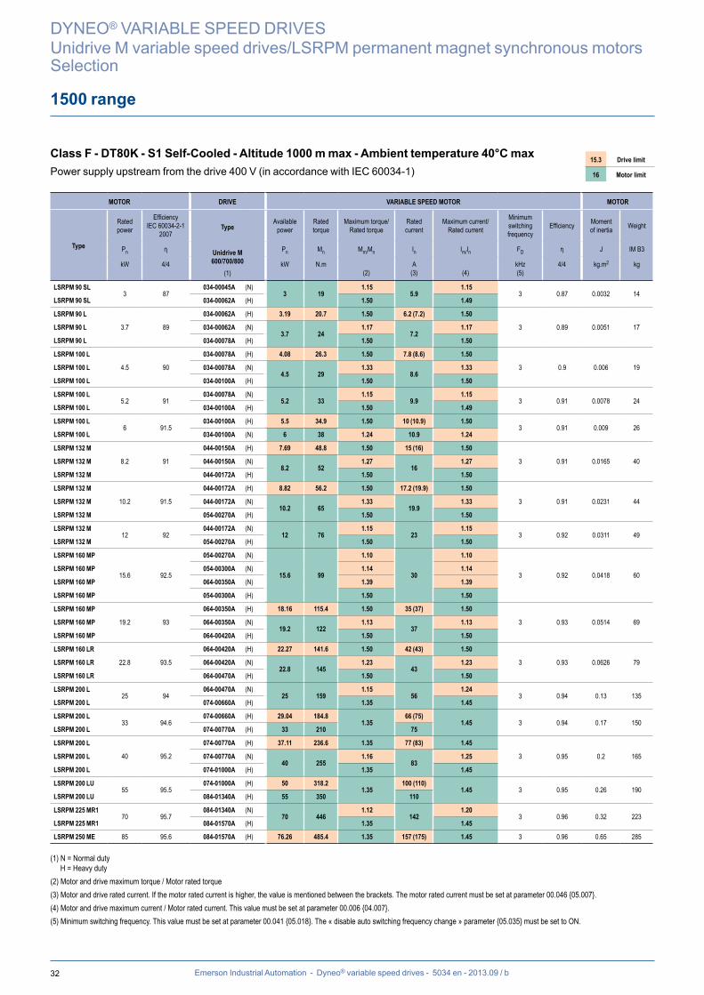
1500 range
Class F - DT80K - S1 Self-Cooled - Altitude 1000 m max - Ambient temperature 40°C maxPower supply upstream from the drive 400 V (in accordance with IEC 60034-1)
15.3 Drive limit
16 Motor limit
DYNEO® VARIABLE SPEED DRIVES
Unidrive M variable speed drives/LSRPM permanent magnet synchronous motorsSelection
MOTOR DRIVE VARIABLE SPEED MOTOR MOTOR
Type
Rated power
Efficiency IEC 60034-2-1
2007
Type
Unidrive M600/700/800
(1)
Available power
Rated torque
Maximum torque/ Rated torque
Rated current
Maximum current/ Rated current
Minimum switching frequency
Efficiency Moment of inertia Weight
Pn η Pn Mn Mm/Mn In Im/In FD η J IM B3
kW 4/4 kW N.m(2)
A(3) (4)
kHz(5)
4/4 kg.m2 kg
LSRPM 90 SL3 87
034-00045A (N)3 19
1.15 5.9
1.15 3 0.87 0.0032 14
LSRPM 90 SL 034-00062A (H) 1.50 1.49
LSRPM 90 L
3.7 89
034-00062A (H) 3.19 20.7 1.50 6.2 (7.2) 1.50
3 0.89 0.0051 17LSRPM 90 L 034-00062A (N)3.7 24
1.17 7.2
1.17
LSRPM 90 L 034-00078A (H) 1.50 1.50
LSRPM 100 L
4.5 90
034-00078A (H) 4.08 26.3 1.50 7.8 (8.6) 1.50
3 0.9 0.006 19LSRPM 100 L 034-00078A (N)4.5 29
1.33 8.6
1.33
LSRPM 100 L 034-00100A (H) 1.50 1.50
LSRPM 100 L5.2 91
034-00078A (N)5.2 33
1.15 9.9
1.15 3 0.91 0.0078 24
LSRPM 100 L 034-00100A (H) 1.50 1.49
LSRPM 100 L6 91.5
034-00100A (H) 5.5 34.9 1.50 10 (10.9) 1.50 3 0.91 0.009 26
LSRPM 100 L 034-00100A (N) 6 38 1.24 10.9 1.24
LSRPM 132 M
8.2 91
044-00150A (H) 7.69 48.8 1.50 15 (16) 1.50
3 0.91 0.0165 40LSRPM 132 M 044-00150A (N)8.2 52
1.27 16
1.27
LSRPM 132 M 044-00172A (H) 1.50 1.50
LSRPM 132 M
10.2 91.5
044-00172A (H) 8.82 56.2 1.50 17.2 (19.9) 1.50
3 0.91 0.0231 44LSRPM 132 M 044-00172A (N)10.2 65
1.33 19.9
1.33
LSRPM 132 M 054-00270A (H) 1.50 1.50
LSRPM 132 M12 92
044-00172A (N)12 76
1.15 23
1.15 3 0.92 0.0311 49
LSRPM 132 M 054-00270A (H) 1.50 1.50
LSRPM 160 MP
15.6 92.5
054-00270A (N)
15.6 99
1.10
30
1.10
3 0.92 0.0418 60LSRPM 160 MP 054-00300A (N) 1.14 1.14
LSRPM 160 MP 064-00350A (N) 1.39 1.39
LSRPM 160 MP 054-00300A (H) 1.50 1.50
LSRPM 160 MP
19.2 93
064-00350A (H) 18.16 115.4 1.50 35 (37) 1.50
3 0.93 0.0514 69LSRPM 160 MP 064-00350A (N)19.2 122
1.13 37
1.13
LSRPM 160 MP 064-00420A (H) 1.50 1.50
LSRPM 160 LR
22.8 93.5
064-00420A (H) 22.27 141.6 1.50 42 (43) 1.50
3 0.93 0.0626 79LSRPM 160 LR 064-00420A (N)22.8 145
1.23 43
1.23
LSRPM 160 LR 064-00470A (H) 1.50 1.50
LSRPM 200 L25 94
064-00470A (N)25 159
1.15 56
1.24 3 0.94 0.13 135
LSRPM 200 L 074-00660A (H) 1.35 1.45
LSRPM 200 L33 94.6
074-00660A (H) 29.04 184.8 1.35
66 (75) 1.45 3 0.94 0.17 150
LSRPM 200 L 074-00770A (H) 33 210 75
LSRPM 200 L
40 95.2
074-00770A (H) 37.11 236.6 1.35 77 (83) 1.45
3 0.95 0.2 165LSRPM 200 L 074-00770A (N)40 255
1.16 83
1.25
LSRPM 200 L 074-01000A (H) 1.35 1.45
LSRPM 200 LU55 95.5
074-01000A (H) 50 318.2 1.35
100 (110) 1.45 3 0.95 0.26 190
LSRPM 200 LU 084-01340A (H) 55 350 110
LSRPM 225 MR170 95.7
084-01340A (N)70 446
1.12 142
1.20 3 0.96 0.32 223
LSRPM 225 MR1 084-01570A (H) 1.35 1.45
LSRPM 250 ME 85 95.6 084-01570A (H) 76.26 485.4 1.35 157 (175) 1.45 3 0.96 0.65 285
(1) N = Normal dutyH = Heavy duty
(2) Motor and drive maximum torque / Motor rated torque(3) Motor and drive rated current. If the motor rated current is higher, the value is mentioned between the brackets. The motor rated current must be set at parameter 00.046 {05.007}.(4) Motor and drive maximum current / Motor rated current. This value must be set at parameter 00.006 {04.007}.(5) Minimum switching frequency. This value must be set at parameter 00.041 {05.018}. The « disable auto switching frequency change » parameter {05.035} must be set to ON.
33Emerson Industrial Automation - Dyneo® variable speed drives - 5034 en - 2013.09 / b
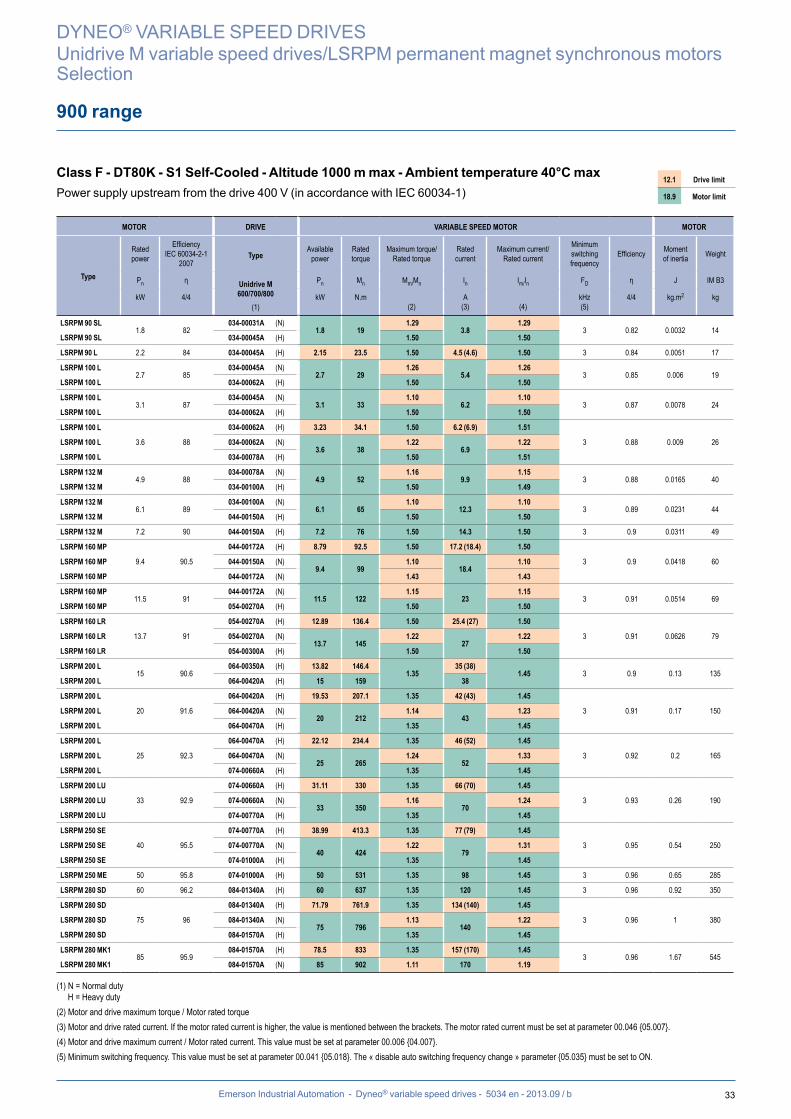
900 range
Class F - DT80K - S1 Self-Cooled - Altitude 1000 m max - Ambient temperature 40°C maxPower supply upstream from the drive 400 V (in accordance with IEC 60034-1)
12.1 Drive limit
18.9 Motor limit
DYNEO® VARIABLE SPEED DRIVES
Unidrive M variable speed drives/LSRPM permanent magnet synchronous motorsSelection
MOTOR DRIVE VARIABLE SPEED MOTOR MOTOR
Type
Rated power
Efficiency IEC 60034-2-1
2007
Type
Unidrive M600/700/800
(1)
Available power
Rated torque
Maximum torque/ Rated torque
Rated current
Maximum current/ Rated current
Minimum switching frequency
Efficiency Moment of inertia Weight
Pn η Pn Mn Mm/Mn In Im/In FD η J IM B3
kW 4/4 kW N.m(2)
A(3) (4)
kHz(5)
4/4 kg.m2 kg
LSRPM 90 SL1.8 82
034-00031A (N)1.8 19
1.29 3.8
1.29 3 0.82 0.0032 14
LSRPM 90 SL 034-00045A (H) 1.50 1.50
LSRPM 90 L 2.2 84 034-00045A (H) 2.15 23.5 1.50 4.5 (4.6) 1.50 3 0.84 0.0051 17
LSRPM 100 L2.7 85
034-00045A (N)2.7 29
1.26 5.4
1.26 3 0.85 0.006 19
LSRPM 100 L 034-00062A (H) 1.50 1.50
LSRPM 100 L3.1 87
034-00045A (N)3.1 33
1.10 6.2
1.10 3 0.87 0.0078 24
LSRPM 100 L 034-00062A (H) 1.50 1.50
LSRPM 100 L
3.6 88
034-00062A (H) 3.23 34.1 1.50 6.2 (6.9) 1.51
3 0.88 0.009 26LSRPM 100 L 034-00062A (N)3.6 38
1.22 6.9
1.22
LSRPM 100 L 034-00078A (H) 1.50 1.51
LSRPM 132 M4.9 88
034-00078A (N)4.9 52
1.16 9.9
1.15 3 0.88 0.0165 40
LSRPM 132 M 034-00100A (H) 1.50 1.49
LSRPM 132 M6.1 89
034-00100A (N)6.1 65
1.10 12.3
1.10 3 0.89 0.0231 44
LSRPM 132 M 044-00150A (H) 1.50 1.50
LSRPM 132 M 7.2 90 044-00150A (H) 7.2 76 1.50 14.3 1.50 3 0.9 0.0311 49
LSRPM 160 MP
9.4 90.5
044-00172A (H) 8.79 92.5 1.50 17.2 (18.4) 1.50
3 0.9 0.0418 60LSRPM 160 MP 044-00150A (N)9.4 99
1.10 18.4
1.10
LSRPM 160 MP 044-00172A (N) 1.43 1.43
LSRPM 160 MP11.5 91
044-00172A (N)11.5 122
1.15 23
1.15 3 0.91 0.0514 69
LSRPM 160 MP 054-00270A (H) 1.50 1.50
LSRPM 160 LR
13.7 91
054-00270A (H) 12.89 136.4 1.50 25.4 (27) 1.50
3 0.91 0.0626 79LSRPM 160 LR 054-00270A (N)13.7 145
1.22 27
1.22
LSRPM 160 LR 054-00300A (H) 1.50 1.50
LSRPM 200 L15 90.6
064-00350A (H) 13.82 146.4 1.35
35 (38) 1.45 3 0.9 0.13 135
LSRPM 200 L 064-00420A (H) 15 159 38
LSRPM 200 L
20 91.6
064-00420A (H) 19.53 207.1 1.35 42 (43) 1.45
3 0.91 0.17 150LSRPM 200 L 064-00420A (N)20 212
1.14 43
1.23
LSRPM 200 L 064-00470A (H) 1.35 1.45
LSRPM 200 L
25 92.3
064-00470A (H) 22.12 234.4 1.35 46 (52) 1.45
3 0.92 0.2 165LSRPM 200 L 064-00470A (N)25 265
1.24 52
1.33
LSRPM 200 L 074-00660A (H) 1.35 1.45
LSRPM 200 LU
33 92.9
074-00660A (H) 31.11 330 1.35 66 (70) 1.45
3 0.93 0.26 190LSRPM 200 LU 074-00660A (N)33 350
1.16 70
1.24
LSRPM 200 LU 074-00770A (H) 1.35 1.45
LSRPM 250 SE
40 95.5
074-00770A (H) 38.99 413.3 1.35 77 (79) 1.45
3 0.95 0.54 250LSRPM 250 SE 074-00770A (N)40 424
1.22 79
1.31
LSRPM 250 SE 074-01000A (H) 1.35 1.45
LSRPM 250 ME 50 95.8 074-01000A (H) 50 531 1.35 98 1.45 3 0.96 0.65 285
LSRPM 280 SD 60 96.2 084-01340A (H) 60 637 1.35 120 1.45 3 0.96 0.92 350
LSRPM 280 SD
75 96
084-01340A (H) 71.79 761.9 1.35 134 (140) 1.45
3 0.96 1 380LSRPM 280 SD 084-01340A (N)75 796
1.13 140
1.22
LSRPM 280 SD 084-01570A (H) 1.35 1.45
LSRPM 280 MK185 95.9
084-01570A (H) 78.5 833 1.35 157 (170) 1.45 3 0.96 1.67 545
LSRPM 280 MK1 084-01570A (N) 85 902 1.11 170 1.19
(1) N = Normal dutyH = Heavy duty
(2) Motor and drive maximum torque / Motor rated torque(3) Motor and drive rated current. If the motor rated current is higher, the value is mentioned between the brackets. The motor rated current must be set at parameter 00.046 {05.007}.(4) Motor and drive maximum current / Motor rated current. This value must be set at parameter 00.006 {04.007}.(5) Minimum switching frequency. This value must be set at parameter 00.041 {05.018}. The « disable auto switching frequency change » parameter {05.035} must be set to ON.
34 Emerson Industrial Automation - Dyneo® variable speed drives - 5034 en - 2013.09 / b
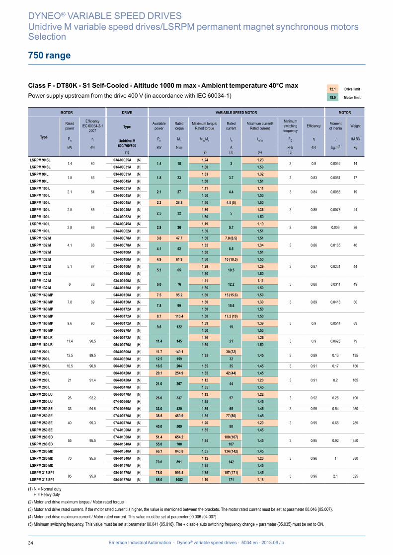
750 range
Class F - DT80K - S1 Self-Cooled - Altitude 1000 m max - Ambient temperature 40°C maxPower supply upstream from the drive 400 V (in accordance with IEC 60034-1)
12.1 Drive limit
18.9 Motor limit
DYNEO® VARIABLE SPEED DRIVES
Unidrive M variable speed drives/LSRPM permanent magnet synchronous motorsSelection
MOTOR DRIVE VARIABLE SPEED MOTOR MOTOR
Type
Rated power
Efficiency IEC 60034-2-1
2007
Type
Unidrive M600/700/800
(1)
Available power
Rated torque
Maximum torque/ Rated torque
Rated current
Maximum current/ Rated current
Minimum switching frequency
Efficiency Moment of inertia Weight
Pn η Pn Mn Mm/Mn In Im/In FD η J IM B3
kW 4/4 kW N.m(2)
A(3) (4)
kHz(5)
4/4 kg.m2 kg
LSRPM 90 SL1.4 80
034-00025A (N)1.4 18
1.24 3
1.23 3 0.8 0.0032 14
LSRPM 90 SL 034-00031A (H) 1.50 1.50
LSRPM 90 L1.8 83
034-00031A (N)1.8 23
1.33 3.7
1.32 3 0.83 0.0051 17
LSRPM 90 L 034-00045A (H) 1.50 1.51
LSRPM 100 L2.1 84
034-00031A (N)2.1 27
1.11 4.4
1.11 3 0.84 0.0066 19
LSRPM 100 L 034-00045A (H) 1.50 1.50
LSRPM 100 L
2.5 85
034-00045A (H) 2.3 28.8 1.50 4.5 (5) 1.50
3 0.85 0.0078 24LSRPM 100 L 034-00045A (N)2.5 32
1.36 5
1.36
LSRPM 100 L 034-00062A (H) 1.50 1.50
LSRPM 100 L2.8 86
034-00045A (N)2.8 36
1.19 5.7
1.19 3 0.86 0.009 26
LSRPM 100 L 034-00062A (H) 1.50 1.51
LSRPM 132 M
4.1 86
034-00078A (H) 3.8 47.7 1.50 7.8 (8.5) 1.51
3 0.86 0.0165 40LSRPM 132 M 034-00078A (N)4.1 52
1.35 8.5
1.34
LSRPM 132 M 034-00100A (H) 1.50 1.51
LSRPM 132 M
5.1 87
034-00100A (H) 4.9 61.9 1.50 10 (10.5) 1.50
3 0.87 0.0231 44LSRPM 132 M 034-00100A (N)5.1 65
1.29 10.5
1.29
LSRPM 132 M 034-00150A (N) 1.50 1.50
LSRPM 132 M6 88
034-00100A (N)6.0 76
1.11 12.2
1.11 3 0.88 0.0311 49
LSRPM 132 M 044-00150A (H) 1.50 1.50
LSRPM 160 MP
7.8 89
044-00150A (H) 7.5 95.2 1.50 15 (15.6) 1.50
3 0.89 0.0418 60LSRPM 160 MP 044-00150A (N)7.8 99
1.30 15.6
1.30
LSRPM 160 MP 044-00172A (H) 1.50 1.50
LSRPM 160 MP
9.6 90
044-00172A (H) 8.7 110.4 1.50 17.2 (19) 1.50
3 0.9 0.0514 69LSRPM 160 MP 044-00172A (N)9.6 122
1.39 19
1.39
LSRPM 160 MP 054-00270A (N) 1.50 1.50
LSRPM 160 LR11.4 90.5
044-00172A (N)11.4 145
1.26 21
1.26 3 0.9 0.0626 79
LSRPM 160 LR 054-00270A (H) 1.50 1.50
LSRPM 200 L12.5 89.5
054-00300A (H) 11.7 149.1 1.35
30 (32) 1.45 3 0.89 0.13 135
LSRPM 200 L 064-00350A (H) 12.5 159 32
LSRPM 200 L 16.5 90.8 064-00350A (H) 16.5 204 1.35 35 1.45 3 0.91 0.17 150
LSRPM 200 L
21 91.4
064-00420A (H) 20.1 254.9 1.35 42 (44) 1.45
3 0.91 0.2 165LSRPM 200 L 064-00420A (N)21.0 267
1.12 44
1.20
LSRPM 200 L 064-00470A (H) 1.35 1.45
LSRPM 200 LU26 92.2
064-00470A (N)26.0 337
1.13 57
1.22 3 0.92 0.26 190
LSRPM 200 LU 074-00660A (H) 1.35 1.45
LSRPM 250 SE 33 94.8 074-00660A (H) 33.0 420 1.35 65 1.45 3 0.95 0.54 250
LSRPM 250 SE
40 95.3
074-00770A (H) 38.5 489.9 1.35 77 (80) 1.45
3 0.95 0.65 285LSRPM 250 SE 074-00770A (N)40.0 509
1.20 80
1.29
LSRPM 250 SE 074-01000A (H) 1.35 1.45
LSRPM 280 SD55 95.5
074-01000A (H) 51.4 654.2 1.35
100 (107) 1.45 3 0.95 0.92 350
LSRPM 280 SD 084-01340A (H) 55.0 700 107
LSRPM 280 MD
70 95.6
084-01340A (H) 66.1 840.8 1.35 134 (142) 1.45
3 0.96 1 380LSRPM 280 MD 084-01340A (N)70.0 891
1.12 142
1.20
LSRPM 280 MD 084-01570A (H) 1.35 1.45
LSRPM 315 SP185 95.9
084-01570A (H) 78.0 993.4 1.35 157 (171) 1.45 3 0.96 2.1 625
LSRPM 315 SP1 084-01570A (N) 85.0 1082 1.10 171 1.18
(1) N = Normal dutyH = Heavy duty
(2) Motor and drive maximum torque / Motor rated torque(3) Motor and drive rated current. If the motor rated current is higher, the value is mentioned between the brackets. The motor rated current must be set at parameter 00.046 {05.007}.(4) Motor and drive maximum current / Motor rated current. This value must be set at parameter 00.006 {04.007}.(5) Minimum switching frequency. This value must be set at parameter 00.041 {05.018}. The « disable auto switching frequency change » parameter {05.035} must be set to ON.

35Emerson Industrial Automation - Dyneo® variable speed drives - 5034 en - 2013.09 / b
DYNEO® VARIABLE SPEED DRIVES
Unidrive M variable speed drives/LSRPM permanent magnet synchronous motors

36 Emerson Industrial Automation - Dyneo® variable speed drives - 5034 en - 2013.09 / b
DYNEO® VARIABLE SPEED DRIVES
Unidrive M variable speed drives/LSRPM permanent magnet synchronous motorsInstallation and options
General information
Influence of the mains supplyEach industrial power supply has its own intrinsic characteristics (short-circuit capability, voltage value and fluctuation, phase imbalance, etc) and supplies equipment some of which can distort its voltage either permanently or temporarily (notches, voltage dips, overvoltage, etc). The quality of the mains supply has an impact on the performance and reliability of electronic equipment, especially variable speed drives.Control Techniques drives are designed to operate with a mains supply typically found on industrial sites throughout the world.However, for each installation, it is important to know the characteristics of the mains supply in order to carry out corrective measures in the event of abnormal conditions.
Transient overvoltagesThere are numerous sources of overvoltages on an electrical installation:• Connection/disconnection of banks of power factor correction capacitors• High-power thyristor-controlled equipment (oven, DC drive, etc)• Overhead power supply
Connection/disconnection of a bank of cos j correction capacitorsConnecting power factor correction capacitors in parallel on the drive power supply line when the drive is running can generate transient overvoltages that are likely to trip the drive safety devices, or even damage it in extreme cases.If banks of power factor correction capacitors are used on the power supply line, make sure that:• The threshold between steps is low enough to avoid causing overvoltage on the line• The capacitors are not permanently connected
Presence of commutation notches on the lineWhen high-power thyristor-controlled equipment is connected on the same line as the drive, it is essential to ensure that the harmonics generated by the commutation notches do not excessively distort the mains voltage and do not create voltage peaks with amplitude higher than 1.6 x mains Vrms. If this is the case, it is essential to take corrective measures to guarantee the mains quality.
Unbalanced power supply In the same way as can be seen on an electric motor, the line phase voltage imbalance of a drive may have consequences on its operation. Please refer to the drive installation manual. Equipotential bondingThe equipotential earth bonding of some industrial sites is not always observed. This lack of equipotential leads to leakage currents which flow via the earth cables (green/yellow), the machine chassis, the pipework, etc, and also via the electrical equipment. In some extreme cases, these currents can trip the drive.It is essential that the earth network is designed and implemented by the installation supervisor so that its impedance is as low as possible, so as to distribute the fault currents and high-frequency currents without them passing through electrical equipment.Metal grounds must be mechanically connected to each other with the largest possible electrical contact area. Under no circumstances can the earth connections designed to protect people, by linking metal grounds to earth via a cable, serve as a substitute for the ground connections (see IEC 61000-5-2).
The immunity and radio-frequency emission level are directly linked to the quality of the ground connections.
Connection of control and encoder cablesWARNING: Strip back the shielding on the metal clamp collars in order to ensure 360° contact.
Metal clamp collars on the shielding
Shielding connected to the 0V
Shielding connected to the 0V
Shielded twisted pairs
Shielded twisted pairs
Cable shielding
Drive connection
Motor connection

37Emerson Industrial Automation - Dyneo® variable speed drives - 5034 en - 2013.09 / b
L1 L2 L3 PE
U V W PE
PE
PE
Mains supply
Switch-fuse
OptionalRFI filter
Optionalline reactor
Encoder
Encoder cable
DYNEO® VARIABLE SPEED DRIVES
Unidrive M variable speed drives/LSRPM permanent magnet synchronous motorsInstallation and options
Installation
The following information is given for guidance only, and should never be used as a substitute for the current standards, nor does it relieve the installer of his responsibility.Depending on the installation, more optional elements can be added to the installation:
Switch-fuse : a padlockable breaking device must be installed to isolate the installation should operator intervention be necessary. This device must provide protection against overheating and short-circuits. The fuse rating is stated in the drive documentation. The switch-fuse can be replaced with a circuit-breaker (with appropriate breaking capacity).
RFI filter : its role is to reduce the drive electromagnetic emissions, and thus comply with EMC standards. Control Techniques drives are, as standard, equipped with an internal RFI filter. Some environments require the addition of an external filter. Please consult the drive documentation to find out the drive conformance levels, with and without an external RFI filter.
Drive power supply cables : these cables do not necessarily need shielding. Their cross-section is recommended in the drive documentation, however, it can be adapted according to the type of cable, installation method, the cable length (voltage drop), etc. See below "Sizing the power cables".
Line reactor: its role is to reduce the risk of damage to the drives following phase imbalance or significant disturbance on the electrical mains supply. The line reactor can also reduce low-frequency harmonics.
Motor power supply cables: these cables must be shielded to ensure EMC conformance of the installation. The cable shielding must be connected over 360° at both ends. At the motor end, special EMC cable glands are available as an option. The cable cross-section is recommended in the drive documentation, however, it can be adapted according to the type of cable, installation method, the cable length (voltage drop), etc. See below "Sizing the power cables".
Encoder cables: shielding the sensor cables is important due to the interferences with power cables. This cable must be laid at least 30 cm away from any power cables. See "Encoders" section.
Sizing the power cables: the drive and motor power supply cables must be sized according to the applicable standard, and according to the design current, stated in the drive documentation.The different factors to be taken into account are:- The installation method: in a conduit, a cable tray, suspended, etc- The type of conductor: copper or aluminium
Once the cable cross-section has been determined, check the voltage drop at the motor terminals. A significant voltage drop results in an increase in the current and additional losses in the motor (overheating).
A motor-drive and transformer system which has been earthed in accordance with good practice will contribute significantly to reducing the voltage on the shaft and the motor casing, resulting in fewer high-frequency leakage currents. Premature breakage of bearings and auxiliary equipment, such as encoders, should also be avoided wherever possible.
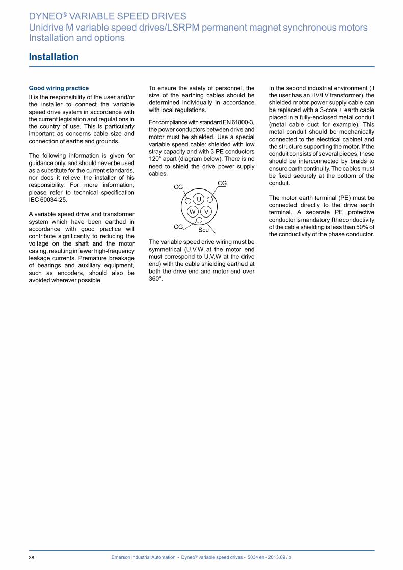
38 Emerson Industrial Automation - Dyneo® variable speed drives - 5034 en - 2013.09 / b
DYNEO® VARIABLE SPEED DRIVES
Unidrive M variable speed drives/LSRPM permanent magnet synchronous motorsInstallation and options
Installation
Good wiring practiceIt is the responsibility of the user and/or the installer to connect the variable speed drive system in accordance with the current legislation and regulations in the country of use. This is particularly important as concerns cable size and connection of earths and grounds.
The following information is given for guidance only, and should never be used as a substitute for the current standards, nor does it relieve the installer of his responsibility. For more information, please refer to technical specification IEC 60034-25.
A variable speed drive and transformer system which have been earthed in accordance with good practice will contribute significantly to reducing the voltage on the shaft and the motor casing, resulting in fewer high-frequency leakage currents. Premature breakage of bearings and auxiliary equipment, such as encoders, should also be avoided wherever possible.
To ensure the safety of personnel, the size of the earthing cables should be determined individually in accordance with local regulations.
For compliance with standard EN 61800-3, the power conductors between drive and motor must be shielded. Use a special variable speed cable: shielded with low stray capacity and with 3 PE conductors 120° apart (diagram below). There is no need to shield the drive power supply cables.
U
V
Scu
CGCG
CG
W
The variable speed drive wiring must be symmetrical (U,V,W at the motor end must correspond to U,V,W at the drive end) with the cable shielding earthed at both the drive end and motor end over 360°.
In the second industrial environment (if the user has an HV/LV transformer), the shielded motor power supply cable can be replaced with a 3-core + earth cable placed in a fully-enclosed metal conduit (metal cable duct for example). This metal conduit should be mechanically connected to the electrical cabinet and the structure supporting the motor. If the conduit consists of several pieces, these should be interconnected by braids to ensure earth continuity. The cables must be fixed securely at the bottom of the conduit.
The motor earth terminal (PE) must be connected directly to the drive earth terminal. A separate PE protective conductor is mandatory if the conductivity of the cable shielding is less than 50% of the conductivity of the phase conductor.
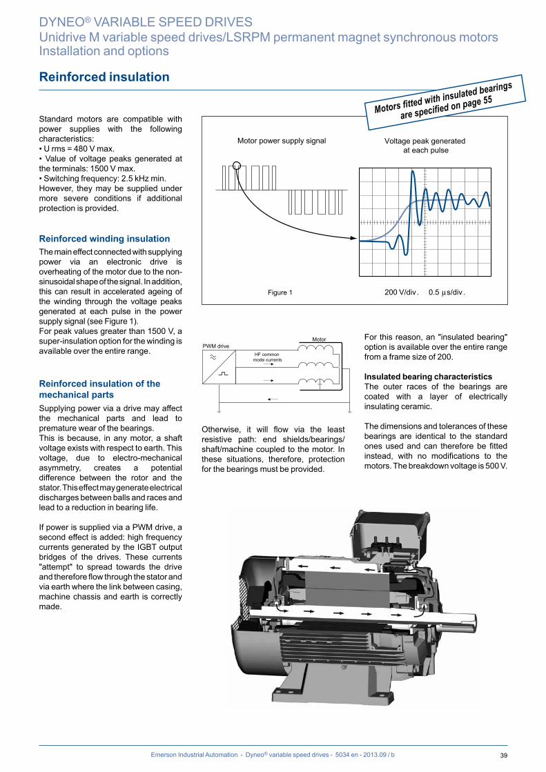
39Emerson Industrial Automation - Dyneo® variable speed drives - 5034 en - 2013.09 / b
Reinforced insulation
200 V/divFigure 1 . 0.5 µs/div.
Voltage peak generated at each pulse
Motor power supply signal
Motors fitted with insulated bearings
are specified on page 55
DYNEO® VARIABLE SPEED DRIVES
Unidrive M variable speed drives/LSRPM permanent magnet synchronous motorsInstallation and options
Standard motors are compatible with power supplies with the following characteristics:• U rms = 480 V max.• Value of voltage peaks generated at the terminals: 1500 V max.• Switching frequency: 2.5 kHz min.However, they may be supplied under more severe conditions if additional protection is provided.
Reinforced winding insulationThe main effect connected with supplying power via an electronic drive is overheating of the motor due to the non-sinusoidal shape of the signal. In addition, this can result in accelerated ageing of the winding through the voltage peaks generated at each pulse in the power supply signal (see Figure 1).For peak values greater than 1500 V, a super-insulation option for the winding is available over the entire range.
Reinforced insulation of the mechanical partsSupplying power via a drive may affect the mechanical parts and lead to premature wear of the bearings.This is because, in any motor, a shaft voltage exists with respect to earth. This voltage, due to electro-mechanical asymmetry, creates a potential difference between the rotor and the stator. This effect may generate electrical discharges between balls and races and lead to a reduction in bearing life.
If power is supplied via a PWM drive, a second effect is added: high frequency currents generated by the IGBT output bridges of the drives. These currents "attempt" to spread towards the drive and therefore flow through the stator and via earth where the link between casing, machine chassis and earth is correctly made.
HF common mode currents
MotorPWM drive
Otherwise, it will flow via the least resistive path: end shields/bearings/shaft/machine coupled to the motor. In these situations, therefore, protection for the bearings must be provided.
For this reason, an "insulated bearing" option is available over the entire range from a frame size of 200.
Insulated bearing characteristicsThe outer races of the bearings are coated with a layer of electrically insulating ceramic.
The dimensions and tolerances of these bearings are identical to the standard ones used and can therefore be fitted instead, with no modifications to the motors. The breakdown voltage is 500 V.
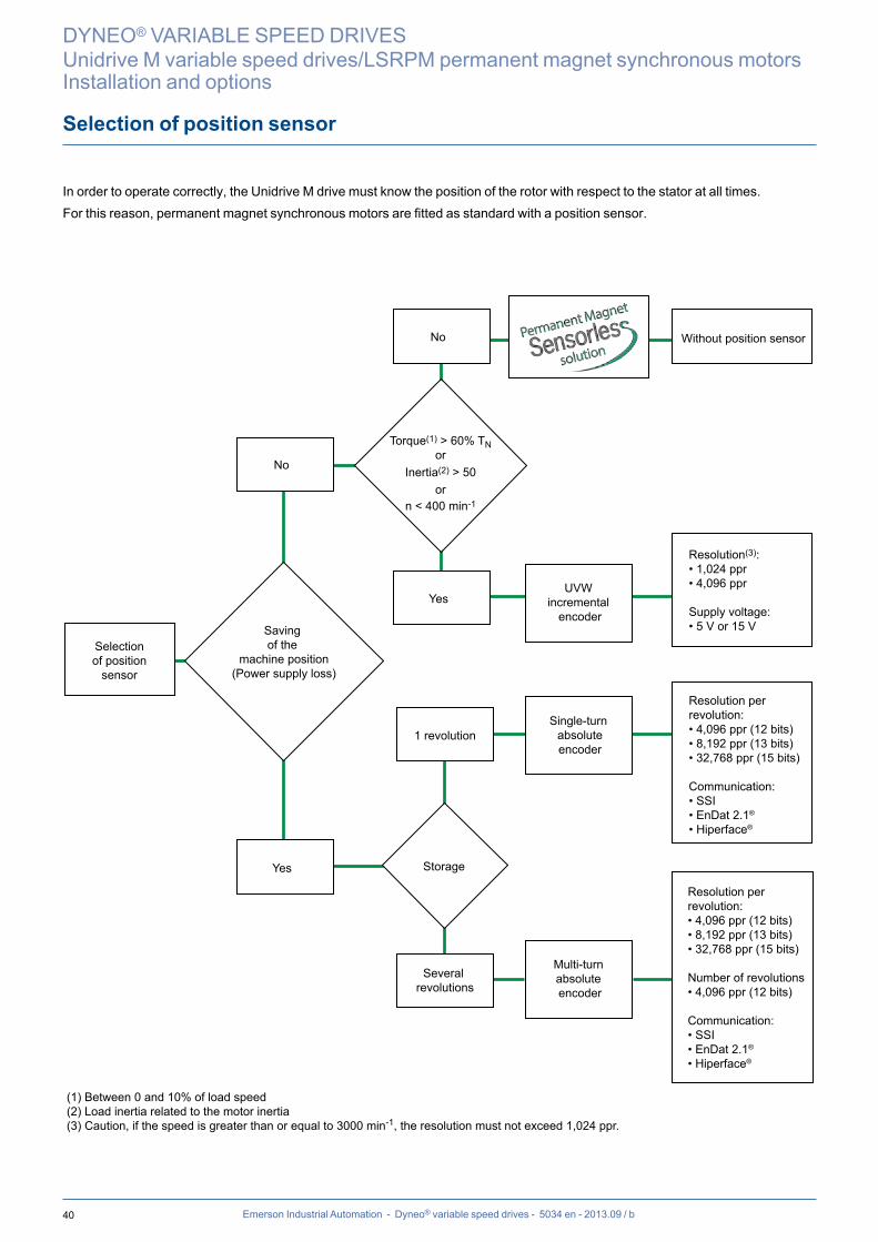
40 Emerson Industrial Automation - Dyneo® variable speed drives - 5034 en - 2013.09 / b
Selection of position sensor
DYNEO® VARIABLE SPEED DRIVES
Unidrive M variable speed drives/LSRPM permanent magnet synchronous motorsInstallation and options
In order to operate correctly, the Unidrive M drive must know the position of the rotor with respect to the stator at all times.For this reason, permanent magnet synchronous motors are fitted as standard with a position sensor.
Storage
Saving of the
machine position(Power supply loss)
Selectionof position
sensor
Multi-turn absolute encoder
Resolution per revolution: • 4,096 ppr (12 bits)• 8,192 ppr (13 bits)• 32,768 ppr (15 bits)
Communication:• SSI• EnDat 2.1®
• Hiperface®
Several revolutions
Single-turn absoluteencoder
Resolution per revolution: • 4,096 ppr (12 bits)• 8,192 ppr (13 bits)• 32,768 ppr (15 bits)
Number of revolutions • 4,096 ppr (12 bits)
Communication:• SSI• EnDat 2.1®
• Hiperface®
1 revolution
No
Yes
Torque(1) > 60% TNor
Inertia(2) > 50or
n < 400 min-1
No
YesUVW
incremental encoder
Resolution(3): • 1,024 ppr• 4,096 ppr
Supply voltage: • 5 V or 15 V
Without position sensor
(1) Between 0 and 10% of load speed(2) Load inertia related to the motor inertia(3) Caution, if the speed is greater than or equal to 3000 min-1, the resolution must not exceed 1,024 ppr.
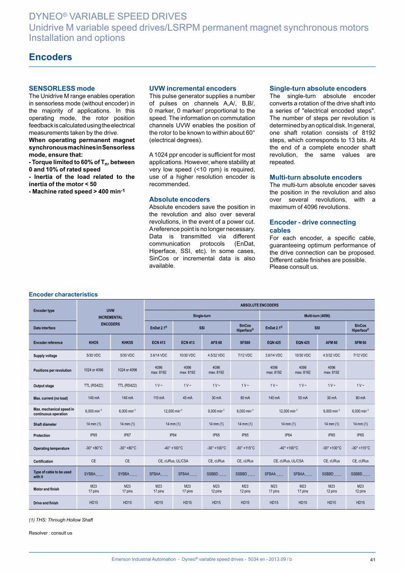
41Emerson Industrial Automation - Dyneo® variable speed drives - 5034 en - 2013.09 / b
SENSORLESS modeThe Unidrive M range enables operation in sensorless mode (without encoder) in the majority of applications. In this operating mode, the rotor position feedback is calculated using the electrical measurements taken by the drive.When operating permanent magnet synchronous machines in Sensorlessmode, ensure that:- Torque limited to 60% of Tn, between0 and 10% of rated speed- Inertia of the load related to the inertia of the motor < 50- Machine rated speed > 400 min-1
UVW incremental encodersThis pulse generator supplies a number of pulses on channels A,A/, B,B/, 0 marker, 0 marker/ proportional to the speed. The information on commutation channels UVW enables the position of the rotor to be known to within about 60° (electrical degrees).
A 1024 ppr encoder is sufficient for most applications. However, where stability at very low speed (<10 rpm) is required, use of a higher resolution encoder is recommended.
Absolute encodersAbsolute encoders save the position in the revolution and also over several revolutions, in the event of a power cut. A reference point is no longer necessary. Data is transmitted via different communication protocols (EnDat, Hiperface, SSI, etc). In some cases, SinCos or incremental data is also available.
Single-turn absolute encodersThe single-turn absolute encoder converts a rotation of the drive shaft into a series of "electrical encoded steps". The number of steps per revolution is determined by an optical disk. In general, one shaft rotation consists of 8192 steps, which corresponds to 13 bits. At the end of a complete encoder shaft revolution, the same values are repeated.
Multi-turn absolute encodersThe multi-turn absolute encoder saves the position in the revolution and also over several revolutions, with a maximum of 4096 revolutions.
Encoder - drive connecting cablesFor each encoder, a specific cable, guaranteeing optimum performance of the drive connection can be proposed. Different cable finishes are possible. Please consult us.
Encoder characteristics
Encoder type UVW INCREMENTAL
ENCODERS
ABSOLUTE ENCODERS
Single-turn Multi-turn (4096)
Data interface EnDat 2.1® SSI SinCosHiperface® EnDat 2.1® SSI SinCos
Hiperface®
Encoder reference KHO5 KHK5S ECN 413 ECN 413 AFS 60 SFS60 EQN 425 EQN 425 AFM 60 SFM 60
Supply voltage 5/30 VDC 5/30 VDC 3.6/14 VDC 10/30 VDC 4.5/32 VDC 7/12 VDC 3.6/14 VDC 10/30 VDC 4.5/32 VDC 7/12 VDC
Positions per revolution 1024 or 4096 1024 or 4096 4096 max: 8192
4096 max: 8192
4096 max: 8192
4096 max: 8192
4096 max: 8192
4096 max: 8192
Output stage TTL (RS422) TTL (RS422) 1 V ~ 1 V ~ 1 V ~ 1 V ~ 1 V ~ 1 V ~ 1 V ~ 1 V ~
Max. current (no load) 140 mA 140 mA 110 mA 45 mA 30 mA 80 mA 140 mA 55 mA 30 mA 80 mA
Max. mechanical speed in continuous operation 6,000 min-1 6,000 min-1 12,000 min-1 9,000 min-1 6,000 min-1 12,000 min-1 9,000 min-1 6,000 min-1
Shaft diameter 14 mm (1) 14 mm (1) 14 mm (1) 14 mm (1) 14 mm (1) 14 mm (1) 14 mm (1) 14 mm (1)
Protection IP65 IP67 IP64 IP65 IP65 IP64 IP65 IP65
Operating temperature -30° +80°C -30° +80°C -40° +100°C -30° +100°C -30° +115°C -40° +100°C -30° +100°C -30° +115°C
Certification CE CE CE, cURus, UL/CSA CE, cURus CE, cURus CE, cURus, UL/CSA CE, cURus CE, cURus
Type of cable to be used with it SYBBA _ _ _ SYBBA _ _ _ SFBAA _ _ _ SFBAA _ _ _ SSBBD _ _ _ SSBBD _ _ _ SFBAA _ _ _ SFBAA _ _ _ SSBBD _ _ _ SSBBD _ _ _
Motor end finish M23 17 pins
M23 17 pins
M2317 pins
M2317 pins
M23 12 pins
M2312 pins
M2317 pins
M2317 pins
M23 12 pins
M2312 pins
Drive end finish HD15 HD15 HD15 HD15 HD15 HD15 HD15 HD15 HD15 HD15
(1) THS: Through Hollow Shaft
Resolver : consult us
Encoders
DYNEO® VARIABLE SPEED DRIVES
Unidrive M variable speed drives/LSRPM permanent magnet synchronous motorsInstallation and options

42 Emerson Industrial Automation - Dyneo® variable speed drives - 5034 en - 2013.09 / b
Forced ventilation
The motors are self-cooled
as standard
DYNEO® VARIABLE SPEED DRIVES
Unidrive M variable speed drives/LSRPM permanent magnet synchronous motorsInstallation and options
To keep the rated torque over the entire speed range, forced ventilation may be necessary.
Forced ventilation characteristics for ranges up to 3600 inclusive(please consult us for 4500 and 5500 ranges)
Motor type FV supply voltage1
FV consumptionFV protection
index2P
(W) I
(A)
LSRPM 90 to 132 single-phase 230 or 400V 100 0.43/0.25 IP 55
LSRPM 160 to 280S3-phase
230/400 V 50 Hz 254/460 V 60 Hz 150 0.94/0.55 IP 55
LSRPM 280M and 3153-phase
230/400 V 50 Hz 254/460 V 60 Hz
200 1.4/0.8 IP 55
1. ± 10% for voltage, ± 2% for frequency.2. Protection index of the forced ventilation installed on the motor.
BlackW V
CP2
CP1
ZUBlue
Brown
Motor type
Capacitors
CP1 CP2
LSRPM 90 to 132
U = 230 V Power supply on U and WU = 400 V Power supply on V and W
3 mf 2 mf
230 or 400 V SINGLE-PHASE FORCED VENTILATIONfor frame size ≤ 132
3-PHASE FORCED VENTILATIONfor frame size > 132
1 SPEED - 2 VOLTAGES L1 - L2 - L3
W2 U2 V2
L1 L2 L3
U1 V1 W1
W2 U2 V2
L1 L2 L3
U1 V1 W1
Cable glands
In certain applications, it is necessary for there to be earth continuity between the cable and the motor earth to guarantee protection of the installation in accordance
with the EMC directive, 89/336/EEC. An optional cable gland with anchorage on shielded cable is therefore available over the entire range.
Type and cable size of cable glands
Cable gland typeCable size
Min. cable Ø (mm) W
Max. cable Ø (mm) A
ISO 16 6 11
ISO 20 7.5 13
ISO 25 12.5 18
ISO 32 17.5 25
ISO 40 24.5 33.5
ISO 50 33 43
ISO 63 42.5 55
The motors are supplied with pre-drilled and
tapped terminal boxes or an undrilled
mounting plate for mounting cable glands
see page 56
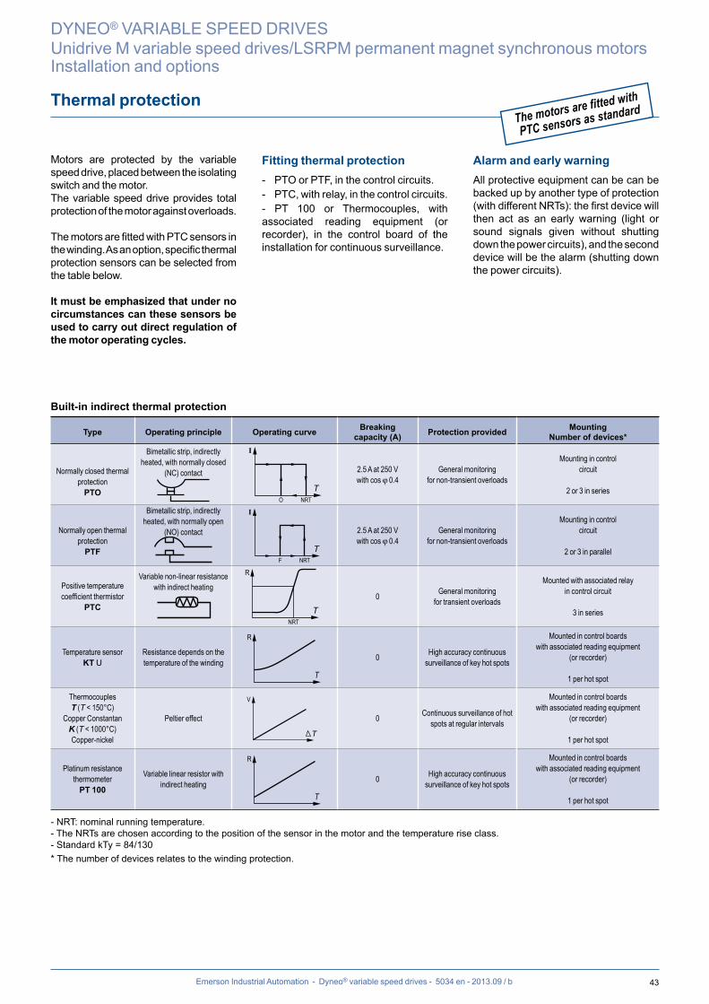
43Emerson Industrial Automation - Dyneo® variable speed drives - 5034 en - 2013.09 / b
Thermal protection
Motors are protected by the variable speed drive, placed between the isolating switch and the motor.The variable speed drive provides total protection of the motor against overloads.
The motors are fitted with PTC sensors in the winding. As an option, specific thermal protection sensors can be selected from the table below.
It must be emphasized that under no circumstances can these sensors be used to carry out direct regulation of the motor operating cycles.
Fitting thermal protection- PTO or PTF, in the control circuits.- PTC, with relay, in the control circuits.- PT 100 or Thermocouples, with associated reading equipment (or recorder), in the control board of the installation for continuous surveillance.
Alarm and early warningAll protective equipment can be can be backed up by another type of protection (with different NRTs): the first device will then act as an early warning (light or sound signals given without shutting down the power circuits), and the second device will be the alarm (shutting down the power circuits).
Built-in indirect thermal protection
Type Operating principle Operating curve Breaking capacity (A) Protection provided Mounting
Number of devices*
Normally closed thermal protection
PTO
Bimetallic strip, indirectly heated, with normally closed
(NC) contact
I
O NRTT
2.5 A at 250 Vwith cos j 0.4
General monitoringfor non-transient overloads
Mounting in control circuit
2 or 3 in series
Normally open thermal protection
PTF
Bimetallic strip, indirectly heated, with normally open
(NO) contact
I
F NRTT
2.5 A at 250 Vwith cos j 0.4
General monitoringfor non-transient overloads
Mounting in control circuit
2 or 3 in parallel
Positive temperature coefficient thermistor
PTC
Variable non-linear resistance with indirect heating
R
NRTT
0 General monitoringfor transient overloads
Mounted with associated relay in control circuit
3 in series
Temperature sensorKT U
Resistance depends on the temperature of the winding
R
T
0 High accuracy continuous surveillance of key hot spots
Mounted in control boards with associated reading equipment
(or recorder)
1 per hot spot
ThermocouplesT (T < 150°C)
Copper ConstantanK (T < 1000°C)Copper-nickel
Peltier effect
V
T
0 Continuous surveillance of hot spots at regular intervals
Mounted in control boards with associated reading equipment
(or recorder)
1 per hot spot
Platinum resistance thermometer
PT 100
Variable linear resistor with indirect heating
R
T
0 High accuracy continuous surveillance of key hot spots
Mounted in control boards with associated reading equipment
(or recorder)
1 per hot spot
- NRT: nominal running temperature.- The NRTs are chosen according to the position of the sensor in the motor and the temperature rise class.- Standard kTy = 84/130* The number of devices relates to the winding protection.
The motors are fitted with
PTC sensors as standard
DYNEO® VARIABLE SPEED DRIVES
Unidrive M variable speed drives/LSRPM permanent magnet synchronous motorsInstallation and options

44
H H1
W D
Emerson Industrial Automation - Dyneo® variable speed drives - 5034 en - 2013.09 / b
Unidrive M
DYNEO® VARIABLE SPEED DRIVES
Unidrive M variable speed drives/LSRPM permanent magnet synchronous motorsDrive dimensions
Drive type Dimensions and weight
Unidrive MH H1 W D Weight
(mm) (mm) (mm) (mm) (kg)
Frame size 03 382 365 83 200 4.5
Frame size 04 391 365 124 200 6.5
Frame size 05 391 365 143 202 7.4
Frame size 06 391 365 210 227 14
Frame size 07 557 508 270 279 28
Frame size 08 803 753 310 290 -
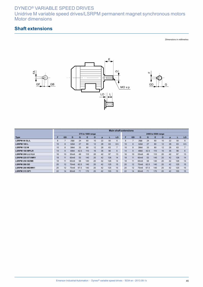
45
E
D
MO x p
F
GD G
FA
GF GB
LLO
Emerson Industrial Automation - Dyneo® variable speed drives - 5034 en - 2013.09 / b
Shaft extensions
DYNEO® VARIABLE SPEED DRIVES
Unidrive M variable speed drives/LSRPM permanent magnet synchronous motorsMotor dimensions
Main shaft extensions375 to 1800 range 2400 to 5500 range
Type F GD D G E O p L LO F GD D G E O p L LOLSRPM 90 SL/L 8 7 28j6 24 60 10 22 50 6 8 7 28j6 24 60 10 22 50 6LSRPM 100 L 10 8 32k6 27 80 12 28 63 8.5 10 8 32k6 27 80 12 28 63 8.5LSRPM 132 M 10 8 38k6 33 80 12 28 63 7 10 8 38k6 33 80 12 28 63 7LSRPM 160 MP/LR 14 9 48k6 42.5 110 16 36 98 6 14 9 48k6 42.5 110 16 36 98 6LSRPM 200 L/L1/LU 16 10 55m6 49 110 20 42 97 13 16 10 55m6 49 110 20 42 97 13LSRPM 225 ST1/MR1 18 11 60m6 53 140 20 42 126 14 18 11 60m6 53 140 20 42 126 14LSRPM 250 SE/ME 18 11 65m6 58 140 20 42 126 14 18 11 65m6 58 140 20 42 126 14LSRPM 280 SD 20 12 70m6 62.5 140 20 42 125 15 20 12 70m6 62.5 140 20 42 125 15LSRPM 280 MD/MK1 20 12 75m6 67.5 140 20 42 125 15 20 12 75m6 67.5 140 20 42 125 15LSRPM 315 SP1 22 14 80m6 71 170 20 42 155 15 22 14 80m6 71 170 20 42 155 15
Dimensions in millimetres
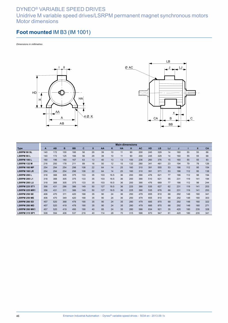
46
J LJ
LB
Ø AC
x
B C
BB
CAA
HD
H HA
AB
AA 4 Ø K
I II
Emerson Industrial Automation - Dyneo® variable speed drives - 5034 en - 2013.09 / b
DYNEO® VARIABLE SPEED DRIVES
Unidrive M variable speed drives/LSRPM permanent magnet synchronous motorsMotor dimensions
Foot mounted IM B3 (IM 1001)
Dimensions in millimetres
Main dimensionsType A AB B BB C X AA K HA H AC HD LB LJ J I II CALSRPM 90 SL 140 172 100 166 56 29 39 10 11 90 200 245 329 14 160 55 55 66LSRPM 90 L 140 172 125 166 56 29 39 10 11 90 200 245 329 14 160 55 55 68
LSRPM 100 L 160 196 140 167 63 13 40 13 13 100 236 260 376 15 160 55 55 93LSRPM 132 M 216 250 178 211 89 16 50 12 15 132 280 341 461 23 194 79 78 126
LSRPM 160 MP 254 294 254 298 108 22 64 14 25 160 310 391 555 53 186 112 95 154LSRPM 160 LR 254 294 254 298 108 22 64 14 25 160 310 391 571 53 186 112 95 138
LSRPM 200 L 318 388 305 375 133 35 103 18.5 36 200 390 476 621 77 186 112 98 194LSRPM 200 L1 318 388 305 375 133 35 103 18.5 36 200 390 510 621 55 231 119 141 194LSRPM 200 LU 318 388 305 375 133 35 103 18.5 36 200 390 476 669 77 186 112 98 244
LSRPM 225 ST1 356 431 286 386 149 50 127 18.5 36 225 390 535 627 62 231 119 141 203LSRPM 225 MR1 356 431 311 386 149 50 127 18.5 36 225 390 535 676 68 231 119 141 253
LSRPM 250 SE 406 470 311 420 168 35 90 24 36 250 479 655 810 68 292 148 180 341LSRPM 250 ME 406 470 349 420 168 35 90 24 36 250 479 655 810 68 292 148 180 303
LSRPM 280 SD 457 520 368 478 190 35 90 24 35 280 479 685 870 68 292 148 180 322LSRPM 280 MD 457 520 419 478 190 35 90 24 35 280 479 685 870 68 292 148 180 271LSRPM 280 MK1 457 520 419 495 190 40 85 24 35 280 586 834 921 35 420 180 235 328LSRPM 315 SP1 508 594 406 537 216 40 114 28 70 315 586 870 947 61 420 180 235 341

47
A
HD
H
I II
HA
AB
AA
M
n ØS
4 ØK
LA
J LJ
LB
T
x
CA B C
Nj6 P
ØAC
BB
Emerson Industrial Automation - Dyneo® variable speed drives - 5034 en - 2013.09 / b
Foot and flange mounted IM B35 (IM 2001)
DYNEO® VARIABLE SPEED DRIVES
Unidrive M variable speed drives/LSRPM permanent magnet synchronous motorsMotor dimensions
Dimensions in millimetres
Main dimensionsType A AB B BB C X AA K HA H AC HD LB LJ J I II CA Sym.LSRPM 90 SL 140 172 100 166 56 29 39 10 11 90 200 245 351 14 160 55 55 66 FF165LSRPM 90 L 140 172 125 166 56 29 39 10 11 90 200 245 351 14 160 55 55 68 FF165
LSRPM 100 L 160 196 140 167 63 13 40 13 13 100 236 260 376 15 160 55 55 93 FF215LSRPM 132 M 216 250 178 211 89 16 50 12 15 132 280 341 461 23 194 79 78 126 FF265
LSRPM 160 MP 254 294 254 298 108 22 64 14 25 160 310 391 555 53 186 112 95 154 FF300LSRPM 160 LR 254 294 254 298 108 22 64 14 25 160 310 391 571 53 186 112 95 138 FF300
LSRPM 200 L 318 388 305 375 133 35 103 18.5 36 200 390 476 621 77 186 112 98 194 FF350LSRPM 200 L1 318 388 305 375 133 35 103 18.5 36 200 390 510 621 55 231 119 141 194 FF350LSRPM 200 LU 318 388 305 375 133 35 103 18.5 36 200 390 476 669 77 186 112 98 244 FF350
LSRPM 225 ST1 356 431 286 386 149 50 127 18.5 36 225 390 535 627 62 231 119 141 203 FF400LSRPM 225 SG 356 420 286 375 149 50 65 18.5 30 225 479 629 810 68 292 148 180 360 FF400LSRPM 225 MR1 356 431 311 386 149 50 127 18.5 36 225 390 535 676 68 231 119 141 253 FF400
LSRPM 250 SE 406 470 311 420 168 35 90 24 36 250 479 655 810 68 292 148 180 341 FF500LSRPM 250 ME 406 470 349 420 168 35 90 24 36 250 479 655 810 68 292 148 180 303 FF500
LSRPM 280 SD 457 520 368 478 190 35 90 24 35 280 479 685 870 68 292 148 180 322 FF500LSRPM 280 MD 457 520 419 478 190 35 90 24 35 280 479 685 870 68 292 148 180 271 FF500LSRPM 280 MK1 457 520 419 495 190 40 85 24 35 280 586 834 921 35 420 180 235 328 FF500LSRPM 315 SP1 508 594 406 537 216 40 114 28 70 315 586 870 947 61 420 180 235 341 FF600
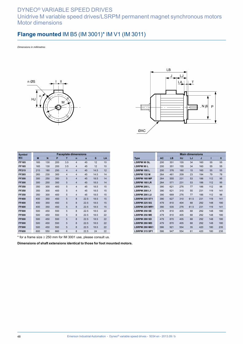
48
HJ
I II
M
n ØS LA
J LJ
LB
T
N j6 P
ØAC
α
Emerson Industrial Automation - Dyneo® variable speed drives - 5034 en - 2013.09 / b
DYNEO® VARIABLE SPEED DRIVES
Unidrive M variable speed drives/LSRPM permanent magnet synchronous motorsMotor dimensions
Flange mounted IM B5 (IM 3001)* IM V1 (IM 3011)
Dimensions in millimetres
Symbol IEC
Faceplate dimensions Main dimensionsM N P T n a S LA Type AC LB HJ LJ J I II
FF165 165 130 200 3.5 4 45 12 10 LSRPM 90 SL 200 351 155 34 160 55 55FF165 165 130 200 3.5 4 45 12 10 LSRPM 90 L 200 351 155 34 160 55 55
FF215 215 180 250 4 4 45 14.5 12 LSRPM 100 L 200 376 160 15 160 55 55FF265 265 230 300 4 4 45 14.5 14 LSRPM 132 M 264 461 209 23 194 79 78
FF300 300 250 350 5 4 45 18.5 14 LSRPM 160 MP 264 555 231 53 186 112 95FF300 300 250 350 5 4 45 18.5 14 LSRPM 160 LR 264 571 231 53 186 112 95
FF350 350 300 400 5 4 45 18.5 15 LSRPM 200 L 390 621 276 77 186 112 98FF350 350 300 400 5 4 45 18.5 15 LSRPM 200 L1 390 621 310 55 231 119 141FF350 350 300 400 5 4 45 18.5 15 LSRPM 200 LU 390 669 276 77 186 112 98
FF400 400 350 450 5 8 22.5 18.5 15 LSRPM 225 ST1 390 627 310 61.5 231 119 141FF400 400 350 450 5 8 22.5 18.5 15 LSRPM 225 SG 479 810 404 68 292 148 180FF400 400 350 450 5 8 22.5 18.5 15 LSRPM 225 MR1 390 535 276 61.5 231 119 141
FF500 500 450 550 5 8 22.5 18.5 22 LSRPM 250 SE 479 810 405 68 292 148 180FF500 500 450 550 5 8 22.5 18.5 22 LSRPM 250 ME 479 810 405 68 292 148 180
FF500 500 450 550 5 8 22.5 18.5 22 LSRPM 280 SD 479 870 405 68 292 148 180FF500 500 450 550 5 8 22.5 18.5 22 LSRPM 280 MD 479 870 405 68 292 148 180FF500 500 450 550 5 8 22.5 18.5 22 LSRPM 280 MK1 586 921 554 35 420 180 235FF600 600 550 660 6 8 22.5 24 22 LSRPM 315 SP1 586 947 554 61 420 180 235
* for a frame size ≥ 250 mm for IM 3001 use, please consult us.
Dimensions of shaft extensions identical to those for foot mounted motors.
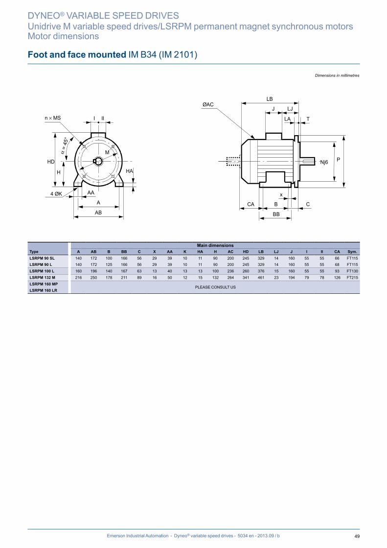
49
A
HD
H
I II
HA
AB
AA
M
4 ØK
LA
J LJ
LB
T
x
CA B C
Nj6 P
ØAC
BB
n × MS
= 45
°
Emerson Industrial Automation - Dyneo® variable speed drives - 5034 en - 2013.09 / b
Foot and face mounted IM B34 (IM 2101)
DYNEO® VARIABLE SPEED DRIVES
Unidrive M variable speed drives/LSRPM permanent magnet synchronous motorsMotor dimensions
Dimensions in millimetres
Main dimensionsType A AB B BB C X AA K HA H AC HD LB LJ J I II CA Sym.LSRPM 90 SL 140 172 100 166 56 29 39 10 11 90 200 245 329 14 160 55 55 66 FT115LSRPM 90 L 140 172 125 166 56 29 39 10 11 90 200 245 329 14 160 55 55 68 FT115
LSRPM 100 L 160 196 140 167 63 13 40 13 13 100 236 260 376 15 160 55 55 93 FT130LSRPM 132 M 216 250 178 211 89 16 50 12 15 132 264 341 461 23 194 79 78 126 FT215
LSRPM 160 MPPLEASE CONSULT US
LSRPM 160 LR
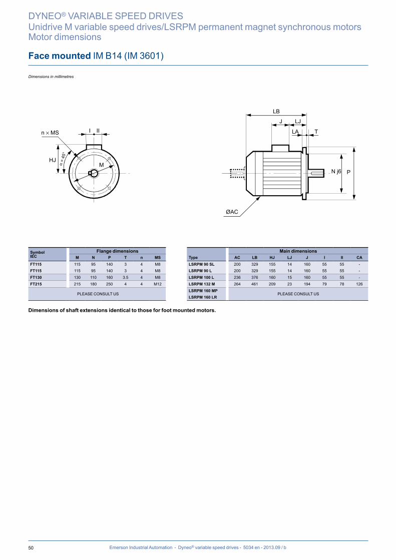
50
HJ
I II
M
LA
J LJ
LB
T
N j6 P
ØAC
n × MS
= 45
°
Emerson Industrial Automation - Dyneo® variable speed drives - 5034 en - 2013.09 / b
DYNEO® VARIABLE SPEED DRIVES
Unidrive M variable speed drives/LSRPM permanent magnet synchronous motorsMotor dimensions
Face mounted IM B14 (IM 3601)
Dimensions in millimetres
Symbol IEC
Flange dimensions Main dimensionsM N P T n MS Type AC LB HJ LJ J I II CA
FT115 115 95 140 3 4 M8 LSRPM 90 SL 200 329 155 14 160 55 55 -FT115 115 95 140 3 4 M8 LSRPM 90 L 200 329 155 14 160 55 55 -
FT130 130 110 160 3.5 4 M8 LSRPM 100 L 236 376 160 15 160 55 55 -FT215 215 180 250 4 4 M12 LSRPM 132 M 264 461 209 23 194 79 78 126
PLEASE CONSULT USLSRPM 160 MP
PLEASE CONSULT USLSRPM 160 LR
Dimensions of shaft extensions identical to those for foot mounted motors.
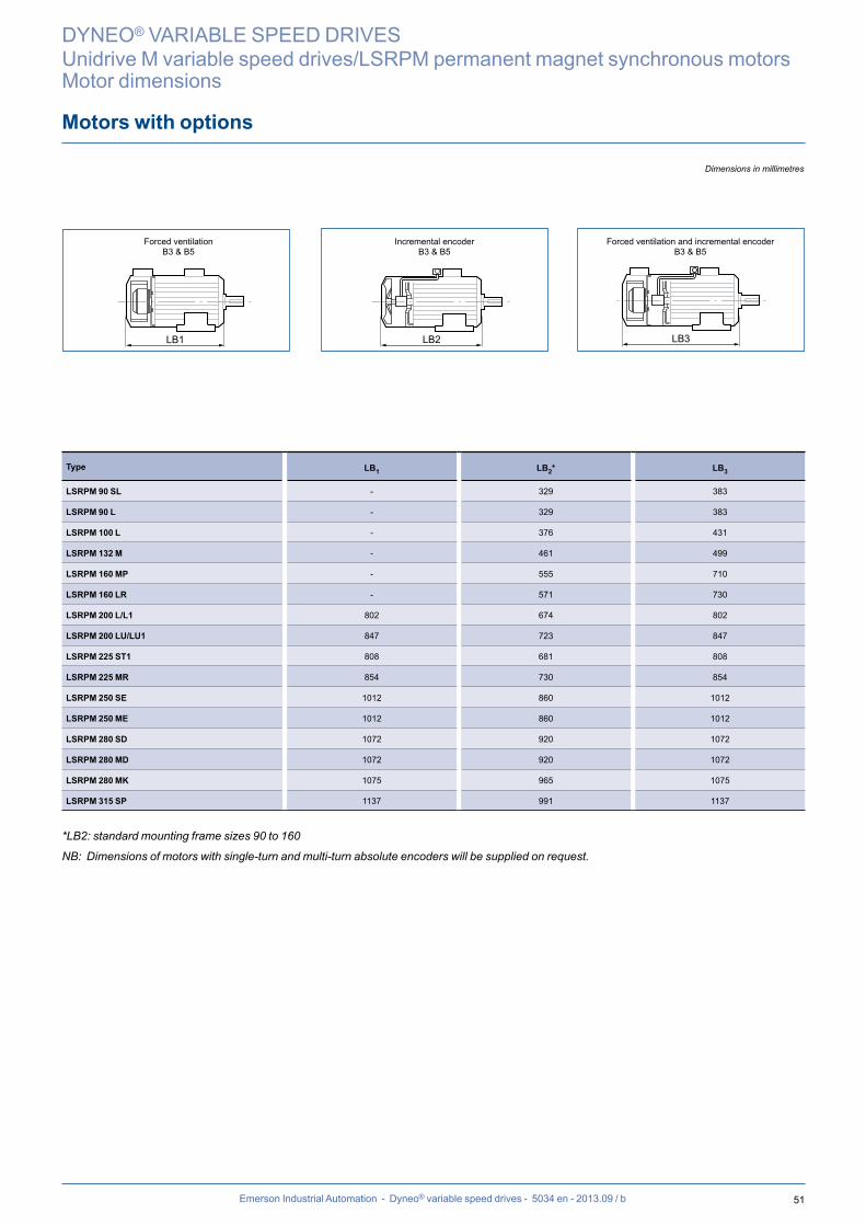
51Emerson Industrial Automation - Dyneo® variable speed drives - 5034 en - 2013.09 / b
Motors with options
DYNEO® VARIABLE SPEED DRIVES
Unidrive M variable speed drives/LSRPM permanent magnet synchronous motorsMotor dimensions
Dimensions in millimetres
LB1 LB2 LB3
Type LB1 LB2* LB3
LSRPM 90 SL - 329 383
LSRPM 90 L - 329 383
LSRPM 100 L - 376 431
LSRPM 132 M - 461 499
LSRPM 160 MP - 555 710
LSRPM 160 LR - 571 730
LSRPM 200 L/L1 802 674 802
LSRPM 200 LU/LU1 847 723 847
LSRPM 225 ST1 808 681 808
LSRPM 225 MR 854 730 854
LSRPM 250 SE 1012 860 1012
LSRPM 250 ME 1012 860 1012
LSRPM 280 SD 1072 920 1072
LSRPM 280 MD 1072 920 1072
LSRPM 280 MK 1075 965 1075
LSRPM 315 SP 1137 991 1137
*LB2: standard mounting frame sizes 90 to 160
NB: Dimensions of motors with single-turn and multi-turn absolute encoders will be supplied on request.
Forced ventilationB3 & B5
Incremental encoderB3 & B5
Forced ventilation and incremental encoderB3 & B5

52 Emerson Industrial Automation - Dyneo® variable speed drives - 5034 en - 2013.09 / b
Definition of “Index of Protection” (IP/IK)
Indices of protection of electrical equipment enclosuresIn accordance with IEC 60034-5 - EN 60034-5 (IP) - IEC 62262 (IK)
IP0
1
2
3
4
5
Tests Definition IP Tests Definition IK Tests Definition
1st number:Protection against solid objects
3rd number:Mechanical protection
Ø 50 mm
Ø 12 mm
No protection
Protected against solid objects larger than 12 mm(e.g. a finger)
Protected against solid objects larger than 50 mm(e.g. accidental contact with the hand)
Protected against solid objects larger than 2.5 mm(e.g. tools, wires)
Ø 2.5 mm
Protected against solid objects larger than 1 mm(e.g. thin tools, small wires)
Ø 1 mm
2nd number:Protection against liquids
0 No protection 00 No protection
1
15°
2
3
4
60°
5
6
7
8 ..m
0.15 m
1 m
Protected against dust (no deposits of harmful material)
Protected against any dust penetration
Protected against prolonged effects of immersion under pressure
Protected against the effects of immersion between 0.15 and 1 m
Protected against projected water comparable to big waves
Projected against jets of water from all directions from a hose
Protected against projected water from all directions
Protected against rain falling at up to 60° from the vertical
Protected against water drops falling at up to 15° from the vertical
Protected against water drops falling vertically(condensation)
01 Impact energy:0.15 J
02 Impact energy:0.20 J
03 Impact energy:0.37 J
05 Impact energy:0.70 J
07 Impact energy:2 J
09 Impact energy:10 J
150 g
10 cm
250 g
15 cm
250 g
20 cm
250 g40 cm
0.5 kg40 cm
2.5 kg40 cm
. . m
6
200 g
10 cm
350 g
20 cm
04
06
081.25 kg
40 cm
10 Impact energy:20 J
5 kg40 cm
Impact energy:5 J
Impact energy:1 J
Impact energy:0.50 J
Example:
Example of an IP 55 machine
IP : Ingress protection
5. : Machine protected against dust and accidental contact. Test result: no dust enters in harmful quantities, no risk of direct contact with rotating
parts. The test will last for 2 hours. .5 : Machine protected against jets of water from all directions from hoses at 3 m distance
with a flow rate of 12.5 l/min at 0.3 bar. The test will last for 3 minutes. Test result: no damage from water projected onto the machine.
In standard configuration the motors are
IP 55/IK 08 for LSRPM
DYNEO® VARIABLE SPEED DRIVES
Unidrive M variable speed drives/LSRPM permanent magnet synchronous motorsMotor construction

53Emerson Industrial Automation - Dyneo® variable speed drives - 5034 en - 2013.09 / b
External finishing
Emerson Industrial Automation motors are protected with a range of surface finishes.The surfaces receive appropriate special treatments, as shown below.
Preparation of surfaces
SUPPORT PARTS TREATMENT
Cast iron End shields Shot blasting + Primer
SteelAccessories Phosphatization + Primer
Terminal boxes - Fan covers Electrostatic painting or Epoxy powder
Aluminium alloy Housings - Terminal boxes Shot blasting
Definition of atmospheresAn atmosphere is said to be harsh when components are attacked by bases, acids or salts. It is said to be corrosive when components are attacked by oxygen.
Paint systems
ATMOSPHERE SYSTEM APPLICATIONS CORROSIVITY CATEGORY *ACC. TO ISO 12944-2
Non-harsh and not very harsh(indoors, rural, industrial)
IaLSRPM - PLSRPM standard 1 polyurethane top coat 20/30 μm C3L
Moderately corrosive: humid, and outdoors (temperate climate) IIa 1 Epoxy base coat 30/40 μm
1 polyurethane top coat 20/30 μm C3M
Corrosive: maritime, very humid (tropical climate) IIIa
1 Epoxy base coat 30/40 μm1 Epoxy intermediate coat 30/40 μm1 polyurethane top coat 20/30 μm
C4M
Substantial chemical attack:frequent contact with bases,
acids, alkaliSurroundings - neutral environment
(not in contact with chlorinated or sulphurous products)
IIIb**1 Epoxy base coat 30/40 μm
1 Epoxy intermediate coat 30/40 μm1 Epoxy top coat 25/35 μm
C4H
Special conditions Very harsh, polluted with chlorinated or sulphurous products
Ve**1 Epoxy base coat 20/30 μm
2 Epoxy intermediate coats, each 35/40 μm1 polyurethane top coat 35/40 μm
C5I-M
161b**1 base coat 50 μm
2 intermediate coats Epoxy 80 μm1 Epoxy top coat 50 μm
C5M-M
System Ia is for moderate climates and System IIa is for general climates as defined in standard IEC 60721.2.1.
* Values given for information only since the substrates vary in nature whereas the standard only takes account of steel substrates.* * Assessment of degree of rusting in accordance with standard ISO 4628 (rust over 1 to 0.5% of the surface)
Emerson Industrial Automation standard paint colour reference:
RAL 3005
DYNEO® VARIABLE SPEED DRIVES
Unidrive M variable speed drives/LSRPM permanent magnet synchronous motorsMotor construction
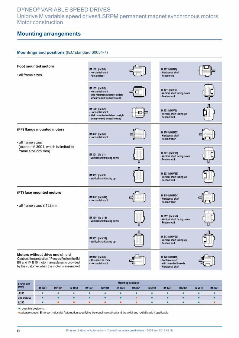
54 Emerson Industrial Automation - Dyneo® variable speed drives - 5034 en - 2013.09 / b
Mounting arrangements
Mountings and positions (IEC standard 60034-7)
Foot mounted motors
• all frame sizesIM 1001 (IM B3)- Horizontal shaft- Feet on floor
IM 1071 (IM B8)- Horizontal shaft- Feet on top
IM 1051 (IM B6)- Horizontal shaft- Wall mounted with feet on left when viewed from drive end
IM 1011 (IM V5)- Vertical shaft facing down- Feet on wall
IM 1061 (IM B7)- Horizontal shaft- Wall mounted with feet on right when viewed from drive end
IM 1031 (IM V6)- Vertical shaft facing up- Feet on wall
(FF) flange mounted motors
• all frame sizes (except IM 3001, which is limited to frame size 225 mm)
IM 3001 (IM B5)- Horizontal shaft
IM 2001 (IM B35)- Horizontal shaft- Feet on floor
IM 3011 (IM V1)- Vertical shaft facing down
IM 2011 (IM V15)- Vertical shaft facing down- Feet on wall
IM 3031 (IM V3)- Vertical shaft facing up
IM 2031 (IM V36)- Vertical shaft facing up- Feet on wall
(FT) face mounted motors
• all frame sizes ≤ 132 mm
IM 3601 (IM B14)- Horizontal shaft
IM 2101 (IM B34)- Horizontal shaft- Feet on floor
IM 3611 (IM V18)- Vertical shaft facing down
IM 2111 (IM V58)- Vertical shaft facing down- Feet on wall
IM 3631 (IM V19)- Vertical shaft facing up
IM 2131 (IM V69)- Vertical shaft facing up- Feet on wall
Motors without drive end shieldCaution: the protection (IP) specified on the IM B9 and IM B15 motor nameplates is provided by the customer when the motor is assembled
IM 9101 (IM B9)- Threaded tie rods- Horizontal shaft
IM 1201 (IM B15)- Foot mounted with threaded tie rods- Horizontal shaft
Frame size(mm)
Mounting positions
IM 1001 IM 1051 IM 1061 IM 1071 IM 1011 IM 1031 IM 3001 IM 3011 IM 3031 IM 2001 IM 2011 IM 2031
≤ 200 l l l l l l l l l l l l
225 and 250 l l l l l l n l l l l l
≥ 280 l n n n n n n l l l l n
l: possible positions.n: please consult Emerson Industrial Automation specifying the coupling method and the axial and radial loads if applicable
DYNEO® VARIABLE SPEED DRIVES
Unidrive M variable speed drives/LSRPM permanent magnet synchronous motorsMotor construction
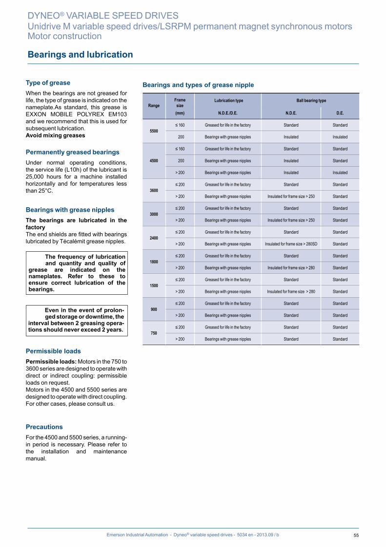
55Emerson Industrial Automation - Dyneo® variable speed drives - 5034 en - 2013.09 / b
Type of grease When the bearings are not greased for life, the type of grease is indicated on the nameplate.As standard, this grease is EXXON MOBILE POLYREX EM103 and we recommend that this is used for subsequent lubrication. Avoid mixing greases
Permanently greased bearings Under normal operating conditions, the service life (L10h) of the lubricant is 25,000 hours for a machine installed horizontally and for temperatures less than 25°C.
Bearings with grease nipples The bearings are lubricated in the factory The end shields are fitted with bearings lubricated by Técalémit grease nipples.
Permissible loadsPermissible loads: Motors in the 750 to 3600 series are designed to operate with direct or indirect coupling: permissible loads on request.Motors in the 4500 and 5500 series are designed to operate with direct coupling. For other cases, please consult us.
PrecautionsFor the 4500 and 5500 series, a running-in period is necessary. Please refer to the installation and maintenance manual.
The frequency of lubrication and quantity and quality of
grease are indicated on the nameplates. Refer to these to ensure correct lubrication of the bearings.
Even in the event of prolon-ged storage or downtime, the
interval between 2 greasing opera-tions should never exceed 2 years.
Bearings and lubrication
Bearings and types of grease nipple
RangeFramesize
Lubrication type Ball bearing type
(mm) N.D.E./D.E. N.D.E. D.E.
5500≤ 160 Greased for life in the factory Standard Standard
200 Bearings with grease nipples Insulated Insulated
4500
≤ 160 Greased for life in the factory Standard Standard
200 Bearings with grease nipples Insulated Standard
> 200 Bearings with grease nipples Insulated Insulated
3600≤ 200 Greased for life in the factory Standard Standard
> 200 Bearings with grease nipples Insulated for frame size > 250 Standard
3000≤ 200 Greased for life in the factory Standard Standard
> 200 Bearings with grease nipples Insulated for frame size > 250 Standard
2400≤ 200 Greased for life in the factory Standard Standard
> 200 Bearings with grease nipples Insulated for frame size > 280SD Standard
1800≤ 200 Greased for life in the factory Standard Standard
> 200 Bearings with grease nipples Insulated for frame size > 280 Standard
1500≤ 200 Greased for life in the factory Standard Standard
> 200 Bearings with grease nipples Insulated for frame size > 280 Standard
900≤ 200 Greased for life in the factory Standard Standard
> 200 Bearings with grease nipples Standard Standard
750≤ 200 Greased for life in the factory Standard Standard
> 200 Bearings with grease nipples Standard Standard
DYNEO® VARIABLE SPEED DRIVES
Unidrive M variable speed drives/LSRPM permanent magnet synchronous motorsMotor construction

56 Emerson Industrial Automation - Dyneo® variable speed drives - 5034 en - 2013.09 / b
Connection
Terminal boxPlaced as standard on the top of the motor near the drive end, the terminal box has IP55 protection.
The standard position of the cable gland baseplate is on the right, seen from the drive end, position A1.
Tightening torque for the nuts on the terminal blocksTerminal M4 M5 M6 M8 M10 M12 M16
TorqueN.m 2 3.2 5 10 20 35 65
t Terminal box positions in relation to the drive end
t Positions of the cable gland in relation to the drive end
2
4
13
A
BD
Standard position
Standard position
Only positions 1 and 3 are possible
Terminal box drilling for cable glands
Motor typePower + auxiliaries
Number of drill holes Drill hole diameter
LSRPM 90 S/SL
2
ISO M25x1.5 + 1xM16LSRPM 100 L
LSRPM 132 M ISO M40x1.5 + 1xM16
LSRPM 160 LR/MP ISO M50x1.5 + 1xM16
LSRPM 200 L/LU
3
2xM40 + 1xM16
LSRPM 200 L1 2xM50 + 1xM16
LSRPM 200 L2/LU2 2xM63 + 1xM16
LSRPM 225 ST1/MR1 2xM50 + 1xM16
LSRPM 225 SG/ST2/SR2 2xM63 + 1xM16
LSRPM 250 SE/ME 2xM63 + 1xM16
LSRPM 250 SE1/ME1 Removable undrilled mounting plate
LSRPM 280 SD/MD 2xM63 + 1xM16
LSRPM 280 MK10 Removable undrilled mounting plate
LSRPM 315 SP1
DYNEO® VARIABLE SPEED DRIVES
Unidrive M variable speed drives/LSRPM permanent magnet synchronous motorsMotor construction
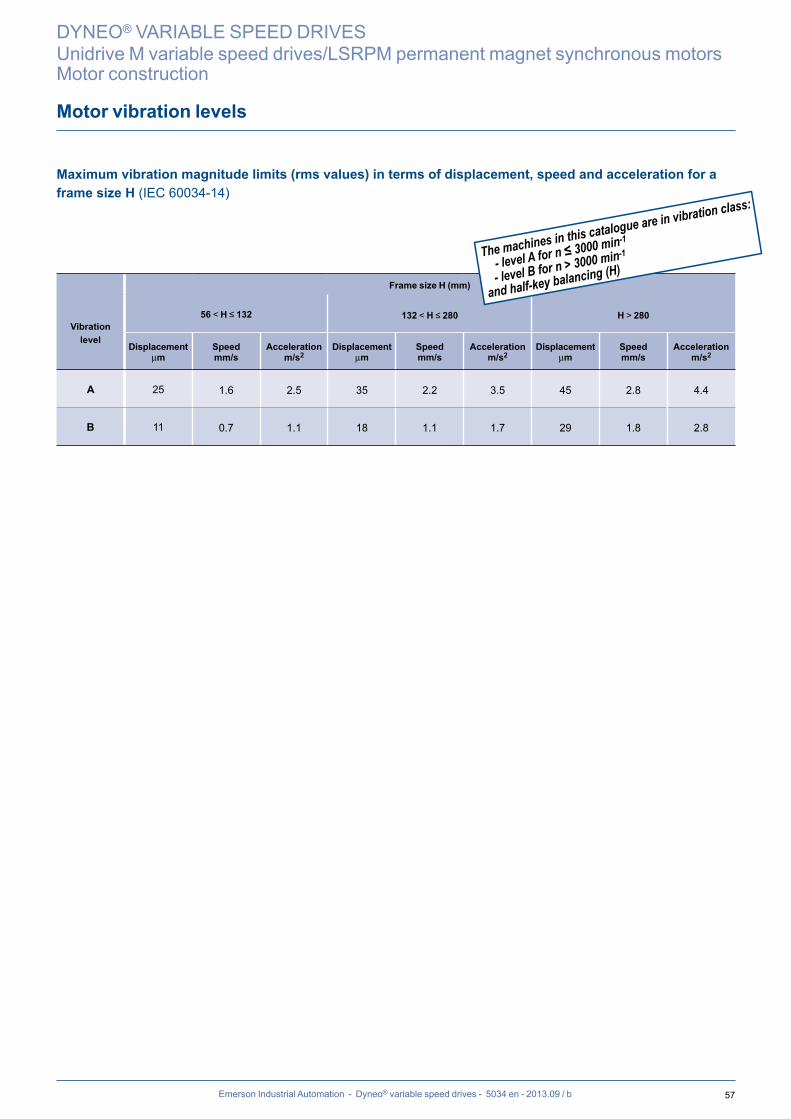
57Emerson Industrial Automation - Dyneo® variable speed drives - 5034 en - 2013.09 / b
Motor vibration levels
Maximum vibration magnitude limits (rms values) in terms of displacement, speed and acceleration for a frame size H (IEC 60034-14)
Frame size H (mm)
Vibration level
56 < H ≤ 132 132 < H ≤ 280 H > 280
Displacementmm
Speedmm/s
Accelerationm/s2
Displacementmm
Speedmm/s
Accelerationm/s2
Displacementmm
Speedmm/s
Accelerationm/s2
A 25 1.6 2.5 35 2.2 3.5 45 2.8 4.4
B 11 0.7 1.1 18 1.1 1.7 29 1.8 2.8
DYNEO® VARIABLE SPEED DRIVES
Unidrive M variable speed drives/LSRPM permanent magnet synchronous motorsMotor construction
The machines in this catalogue are in vibration class:
- level A for n ≤ 3000 min-1
- level B for n > 3000 min-1
and half-key balancing (H)

58 Emerson Industrial Automation - Dyneo® variable speed drives - 5034 en - 2013.09 / b
Quality commitment
DYNEO® VARIABLE SPEED DRIVES
Unidrive M variable speed drives/LSRPM permanent magnet synchronous motorsGeneral information
ISO 9001 : 2008
Emerson Industrial Automation has entrusted the certification of its expertise to various international organisations.Certification is granted by independent professional auditors, and recognises the high standards of the company's quality assurance procedures. All activities resulting in the final version of the machine have therefore received official certification ISO 9001: 2008 from the DNV. Similarly, our environmental approach has enabled us to obtain certification ISO 14001: 2004.Products for particular applications or those designed to operate in specific environments are also approved or certified by the following organisations: LCIE, DNV, INERIS, EFECTIS, UL, BSRIA, TUV, GOST, which check their technical performance against the various standards or recommendations.
Emerson Industrial Automation's quality management system is based on:
- Control of procedures right from the initial sales offering until delivery to the customer, including design, manufactur-ing start-up and production
- A total quality policy based on making continuous progress in improving operational procedures, involving all departments in the company in order to give customer satisfaction as regards delivery times, conformity and cost
- Indicators used to monitor procedure performance
- Corrective actions and advancements with tools such as FMECA, QFD, MAVP, MSP/MSQ and Hoshin type improve-ment workshops on flows, process re-engineering, plus Lean Manufacturing and Lean Office
- Annual surveys, opinion polls and regular visits to customers in order to ascertain and detect their expectations
Personnel are trained and take part in analyses and actions for continuous improvement of our procedures.
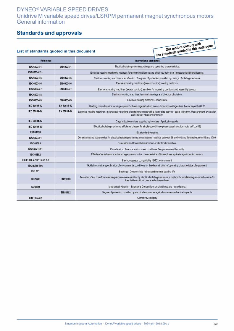
59Emerson Industrial Automation - Dyneo® variable speed drives - 5034 en - 2013.09 / b
DYNEO® VARIABLE SPEED DRIVES
Unidrive M variable speed drives/LSRPM permanent magnet synchronous motorsGeneral information
Standards and approvals
List of standards quoted in this document
Reference International standards
IEC 60034-1 EN 60034-1 Electrical rotating machines: ratings and operating characteristics.
IEC 60034-2-1 Electrical rotating machines: methods for determining losses and efficiency from tests (measured additional losses).
IEC 60034-5 EN 60034-5 Electrical rotating machines: classification of degrees of protection provided by casings of rotating machines.
IEC 60034-6 EN 60034-6 Electrical rotating machines (except traction): cooling methods.
IEC 60034-7 EN 60034-7 Electrical rotating machines (except traction): symbols for mounting positions and assembly layouts.
IEC 60034-8 Electrical rotating machines: terminal markings and direction of rotation.
IEC 60034-9 EN 60034-9 Electrical rotating machines: noise limits.
IEC 60034-12 EN 60034-12 Starting characteristics for single-speed 3-phase cage induction motors for supply voltages less than or equal to 660V.
IEC 60034-14 EN 60034-14 Electrical rotating machines: mechanical vibrations of certain machines with a frame size above or equal to 56 mm. Measurement, evaluation and limits of vibrational intensity.
IEC 60034-17 Cage induction motors supplied by inverters - Application guide.
IEC 60034-30 Electrical rotating machines: efficiency classes for single-speed three-phase cage induction motors (Code IE)
IEC 60038 IEC standard voltages.
IEC 60072-1 Dimensions and power series for electrical rotating machines: designation of casings between 56 and 400 and flanges between 55 and 1080.
IEC 60085 Evaluation and thermal classification of electrical insulation.
IEC 60721-2-1 Classification of natural environment conditions. Temperature and humidity.
IEC 60892 Effects of an imbalance in the voltage system on the characteristics of three-phase squirrel-cage induction motors.
IEC 61000-2-10/11 and 2-2 Electromagnetic compatibility (EMC): environment.
IEC guide 106 Guidelines on the specification of environmental conditions for the determination of operating characteristics of equipment.
ISO 281 Bearings - Dynamic load ratings and nominal bearing life.
ISO 1680 EN 21680 Acoustics - Test code for measuring airborne noise emitted by electrical rotating machines: a method for establishing an expert opinion for free field conditions over a reflective surface.
ISO 8821 Mechanical vibration - Balancing. Conventions on shaft keys and related parts.
EN 50102 Degree of protection provided by electrical enclosures against extreme mechanical impacts.
ISO 12944-2 Corrosivity category
Our motors comply with
the standards quoted in this catalogue
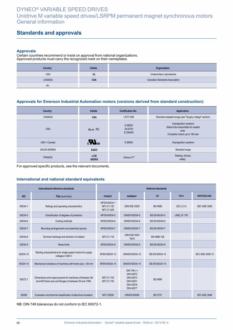
60 Emerson Industrial Automation - Dyneo® variable speed drives - 5034 en - 2013.09 / b
DYNEO® VARIABLE SPEED DRIVES
Unidrive M variable speed drives/LSRPM permanent magnet synchronous motorsGeneral information
Standards and approvals
Approvals Certain countries recommend or insist on approval from national organizations.Approved products must carry the recognized mark on their nameplates.
Country Initials Organization
USA UL Underwriters Laboratories
CANADA CSA Canadian Standards Association
etc.
Approvals for Emerson Industrial Automation motors (versions derived from standard construction):
Country Initials Certification No. Application
CANADA CSA LR 57 008 Standard adapted range (see "Supply voltage" section)
USA UL or E 68554SA 6704E 206450
Impregnation systemsStator/rotor assemblies for sealed
unitsComplete motors up to 160 size
USA + Canada C US E 68554 Impregnation systems
SAUDI ARABIA SASO Standard range
FRANCE LCIEINERIS
Various nos Sealing, shocks, safety
For approved specific products, see the relevant documents.
International and national standard equivalents
International reference standards National standards
IEC Title (summary) FRANCE GERMANY UK ITALY SWITZERLAND
60034-1 Ratings and operating characteristics NFEN 60034-1
NFC 51-120NFC 51-200
DIN/VDE O530 BS 4999 CEI 2.3.VI. SEV ASE 3009
60034-5 Classification of degrees of protection NFEN 60034-5 DIN/EN 60034-5 BS EN 60034-5 UNEL B 1781
60034-6 Cooling methods NFEN 60034-6 DIN/EN 60034-6 BS EN 60034-6
60034-7 Mounting arrangements and assembly layouts NFEN 60034-7 DIN/EN 60034-7 BS EN 60034-7
60034-8 Terminal markings and direction of rotation NFC 51 118 DIN/VDE 0530Teil 8 BS 4999-108
60034-9 Noise limits NFEN 60034-9 DIN/EN 60034-9 BS EN 60034-9
60034-12 Starting characteristics for single-speed motors for supply voltages ≤ 660 V NFEN 60034-12 DIN/EN 60034-12 BS EN 60034-12 SEV ASE 3009-12
60034-14 Mechanical vibrations of machines with frame size ≥ 56 mm NFEN 60034-14 DIN/EN 60034-14 BS EN 60034-14
60072-1 Dimensions and output powers for machines of between 56 and 400 frame size and flanges of between 55 and 1080.
NFC 51 104NFC 51 105
DIN 748 (~)DIN 42672DIN 42673DIN 42631DIN 42676DIN 42677
BS 4999
60085 Evaluation and thermal classification of electrical insulation NFC 26206 DIN/EN 60085 BS 2757 SEV ASE 3584
NB: DIN 748 tolerances do not conform to IEC 60072-1.
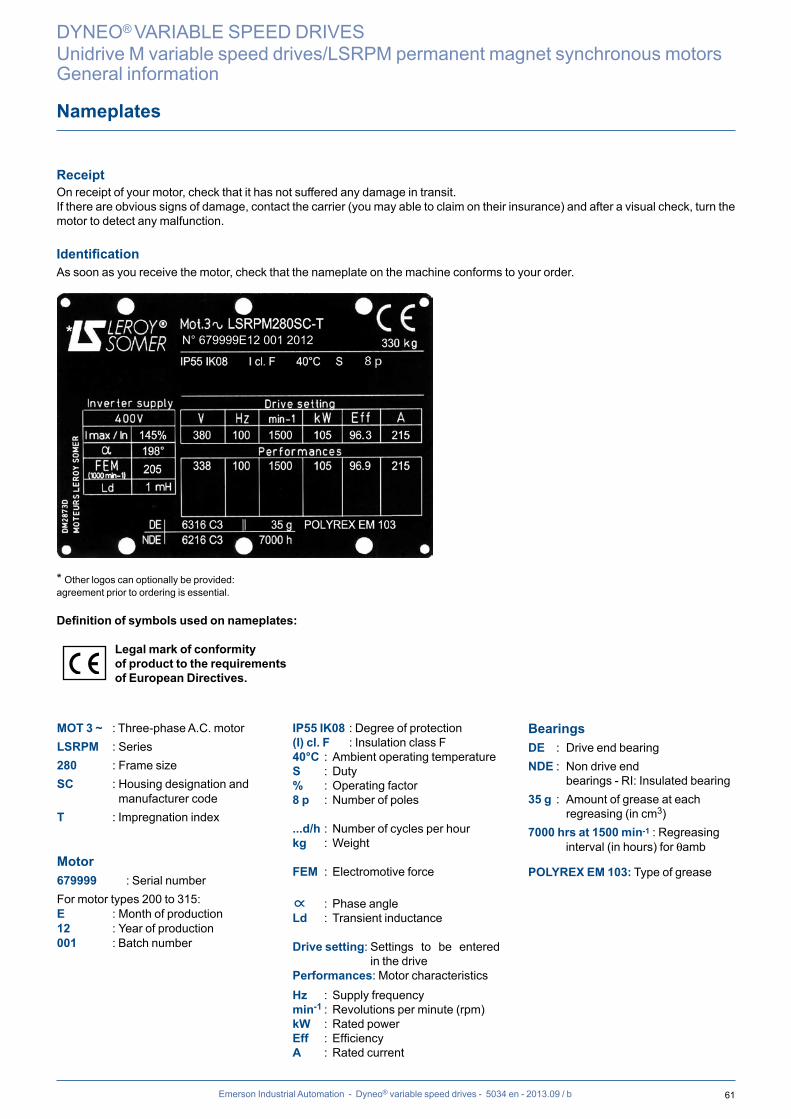
61Emerson Industrial Automation - Dyneo® variable speed drives - 5034 en - 2013.09 / b
DYNEO® VARIABLE SPEED DRIVES
Unidrive M variable speed drives/LSRPM permanent magnet synchronous motorsGeneral information
Nameplates
ReceiptOn receipt of your motor, check that it has not suffered any damage in transit. If there are obvious signs of damage, contact the carrier (you may able to claim on their insurance) and after a visual check, turn the motor to detect any malfunction.
IdentificationAs soon as you receive the motor, check that the nameplate on the machine conforms to your order.
* Other logos can optionally be provided:agreement prior to ordering is essential.
Definition of symbols used on nameplates:
Legal mark of conformity of product to the requirements of European Directives.
MOT 3 ~ : Three-phase A.C. motorLSRPM : Series280 : Frame sizeSC : Housing designation and
manufacturer codeT : Impregnation index
Motor679999 : Serial numberFor motor types 200 to 315:E : Month of production12 : Year of production001 : Batch number
IP55 IK08 : Degree of protection(I) cl. F : Insulation class F40°C : Ambient operating temperatureS : Duty% : Operating factor8 p : Number of poles
...d/h : Number of cycles per hourkg : Weight
FEM : Electromotive force
∝ : Phase angleLd : Transient inductance
Drive setting: Settings to be entered in the drive
Performances: Motor characteristicsHz : Supply frequencymin-1 : Revolutions per minute (rpm)kW : Rated powerEff : EfficiencyA : Rated current
Bearings DE : Drive end bearingNDE : Non drive end bearings - RI: Insulated bearing35 g : Amount of grease at each
regreasing (in cm3)7000 hrs at 1500 min-1 : Regreasing
interval (in hours) for qamb
POLYREX EM 103: Type of grease
* N° 679999E12 001 2012

62 Emerson Industrial Automation - Dyneo® variable speed drives - 5034 en - 2013.09 / b
The configurator can be used to choose the most suitable motor and variable speed and provides the technical spe-cifications and corresponding drawings.
To register online:www.leroy-somer.com/en/solutions_a n d _ s e r v i c e s / d r i v e _ s y s t e m s /configurator
• Help with product selection• Print-outs of technical specifications• Print-outs of 2D and 3D CAD files• The equivalent of 300 catalogues in 10
languages
Configurator
DYNEO® VARIABLE SPEED DRIVES
Unidrive M variable speed drives/LSRPM permanent magnet synchronous motorsGeneral information


- 201
3.10
/ i
The Emerson logo is a trademark and service mark of Emerson Electric Co. © 2013
Moteurs Leroy-Somer SAS - RCS 338 567 258 ANGOULÊME - Capital de 65 800 512 €
en- 2
013.
10 /
ien
www.emersonindustrial.com
© - This document is the property of Emerson Industrial Automation, it can not be reproduced in any form without prior written authorization.Emerson Industrial Automation reserves the right to modify the design, technical speci�cations and dimensions of the products shown in this document.
The descriptions cannot in any way be considered contractual.
Related Documents