Dynamics of retreating slabs: 2. Insights from three-dimensional laboratory experiments Francesca Funiciello 1 Institute of Geophysics, ETH-Ho ¨nggerberg, Zu ¨rich, Switzerland Claudio Faccenna Dipartimento di Scienze Geologiche, Universita’ degli Studi ‘‘Roma Tre,’’ Rome, Italy Domenico Giardini and Klaus Regenauer-Lieb Institute of Geophysics, ETH-Ho ¨nggerberg, Zu ¨rich, Switzerland Received 6 August 2001; revised 28 August 2002; accepted 1 October 2002; published 19 April 2003. [1] A laboratory analogue of a three-layer linear viscous slab-upper mantle-lower mantle system is established in a silicone putty, honey and crystallized honey tank experiment. The same setup as in the numerical investigation (part 1) is used. We focus on the interaction of the slab with the induced passive mantle flow by widely varying the mantle volume flux boundary conditions. In our numerical experiments the lateral volume flux was set to zero. In interpreting the results relative to the real Earth, the base of the box is taken as the bottom of the mantle convection system, while the lateral boundaries may be associated with the presence of other nearby slabs. Dynamic force equilibrium, assessed on the basis of an analytical review of forces, is described for four different phases: (1) the subduction initiation instability, (2) the accelerating dynamic free fall phase of the slab, (3) the dynamic interaction with the 660-km discontinuity, and (4) a final phase of steady state trench retreat. Phase 3 is an important feature not observed in the numerical experiments. This highly dynamic phase of interrupted trench retreat can therefore be attributed to boundary conditions on mantle volume flux. On the basis of integration constants of force equilibrium in phases 2 and 4 we identify two different classes of volume flux: one in which the lateral boundary can be considered open and the other class where it is ‘‘closed.’’ Closed boundary condition cases are obtained if any of the lateral box boundaries are 600 km away from the slab. Assuming a one-to-one relation between trench retreat and back arc spreading, enigmatic observations of episodic opening of back arc basins can be explained by our experimental observations. INDEX TERMS: 8120 Tectonophysics: Dynamics of lithosphere and mantle—general; 8121 Tectonophysics: Dynamics, convection currents and mantle plumes; 8150 Tectonophysics: Evolution of the Earth: Plate boundary—general (3040); 8168 Tectonophysics: Evolution of the Earth: Stresses—general; KEYWORDS: laboratory experiments, subduction, convection, episodicity Citation: Funiciello, F., C. Faccenna, D. Giardini, and K. Regenauer-Lieb, Dynamics of retreating slabs: 2. Insights from three- dimensional laboratory experiments, J. Geophys. Res., 108(B4), 2207, doi:10.1029/2001JB000896, 2003. 1. Introduction [2] Trenches represent areas of localized downwellings, where one plate dives beneath another into the mantle. Trenches are not stationary. Most of them moved and move in the hot spot reference frame toward the subducting plate in a ‘‘retrograde’’ fashion as a direct consequence of the negative buoyancy of the subducting oceanic lithosphere [Chase, 1978; Uyeda and Kanamori, 1979; Dewey , 1980; Garfunkel et al., 1986]. The Pacific boundaries represent the most prominent case of ‘‘retreating’’ trenches (Figure 1). [3] The most direct evidence of retreat is the formation of back arc basins [Uyeda and Kanamori, 1979]. Their open- ing is kinematically linked with the retreat of the trench toward the subducting plate and/or with the motion of the upper plate away from the trench [Chase, 1978; Dewey , 1980; DeMets et al., 1990]. The average rate of spreading of these basins is variable, ranging presently between a few millimeters per year and up to a maximum of 16 cm yr 1 [Jarrard, 1986; Bevis et al., 1995], but spreading rates are not constant. The evolution of a back arc basin is irregular in time and restricted to a few tens of million years [Karig, 1971]; the evolution ends in some cases, with the jump of the spreading center toward the trench, after a period of JOURNAL OF GEOPHYSICAL RESEARCH, VOL. 108, NO. B4, 2207, doi:10.1029/2001JB000896, 2003 1 Now at Dipartimento di Scienze Geologiche, Universita’ degli Studi ‘‘Roma Tre,’’ Rome, Italy. Copyright 2003 by the American Geophysical Union. 0148-0227/03/2001JB000896$09.00 ETG 12 - 1

Welcome message from author
This document is posted to help you gain knowledge. Please leave a comment to let me know what you think about it! Share it to your friends and learn new things together.
Transcript
Dynamics of retreating slabs:
2. Insights from three-dimensional laboratory experiments
Francesca Funiciello1
Institute of Geophysics, ETH-Honggerberg, Zurich, Switzerland
Claudio FaccennaDipartimento di Scienze Geologiche, Universita’ degli Studi ‘‘Roma Tre,’’ Rome, Italy
Domenico Giardini and Klaus Regenauer-LiebInstitute of Geophysics, ETH-Honggerberg, Zurich, Switzerland
Received 6 August 2001; revised 28 August 2002; accepted 1 October 2002; published 19 April 2003.
[1] A laboratory analogue of a three-layer linear viscous slab-upper mantle-lower mantlesystem is established in a silicone putty, honey and crystallized honey tank experiment.The same setup as in the numerical investigation (part 1) is used. We focus on theinteraction of the slab with the induced passive mantle flow by widely varying the mantlevolume flux boundary conditions. In our numerical experiments the lateral volume fluxwas set to zero. In interpreting the results relative to the real Earth, the base of the box istaken as the bottom of the mantle convection system, while the lateral boundaries may beassociated with the presence of other nearby slabs. Dynamic force equilibrium, assessed onthe basis of an analytical review of forces, is described for four different phases: (1) thesubduction initiation instability, (2) the accelerating dynamic free fall phase of the slab, (3)the dynamic interaction with the 660-km discontinuity, and (4) a final phase of steady statetrench retreat. Phase 3 is an important feature not observed in the numerical experiments.This highly dynamic phase of interrupted trench retreat can therefore be attributed toboundary conditions on mantle volume flux. On the basis of integration constants of forceequilibrium in phases 2 and 4 we identify two different classes of volume flux: one inwhich the lateral boundary can be considered open and the other class where it is‘‘closed.’’ Closed boundary condition cases are obtained if any of the lateral boxboundaries are 600 km away from the slab. Assuming a one-to-one relation betweentrench retreat and back arc spreading, enigmatic observations of episodic opening of backarc basins can be explained by our experimental observations. INDEX TERMS: 8120
Tectonophysics: Dynamics of lithosphere and mantle—general; 8121 Tectonophysics: Dynamics, convection
currents and mantle plumes; 8150 Tectonophysics: Evolution of the Earth: Plate boundary—general (3040);
8168 Tectonophysics: Evolution of the Earth: Stresses—general; KEYWORDS: laboratory experiments,
subduction, convection, episodicity
Citation: Funiciello, F., C. Faccenna, D. Giardini, and K. Regenauer-Lieb, Dynamics of retreating slabs: 2. Insights from three-
dimensional laboratory experiments, J. Geophys. Res., 108(B4), 2207, doi:10.1029/2001JB000896, 2003.
1. Introduction
[2] Trenches represent areas of localized downwellings,where one plate dives beneath another into the mantle.Trenches are not stationary. Most of them moved and movein the hot spot reference frame toward the subducting platein a ‘‘retrograde’’ fashion as a direct consequence of thenegative buoyancy of the subducting oceanic lithosphere[Chase, 1978; Uyeda and Kanamori, 1979; Dewey, 1980;
Garfunkel et al., 1986]. The Pacific boundaries represent themost prominent case of ‘‘retreating’’ trenches (Figure 1).[3] The most direct evidence of retreat is the formation of
back arc basins [Uyeda and Kanamori, 1979]. Their open-ing is kinematically linked with the retreat of the trenchtoward the subducting plate and/or with the motion of theupper plate away from the trench [Chase, 1978; Dewey,1980; DeMets et al., 1990]. The average rate of spreading ofthese basins is variable, ranging presently between a fewmillimeters per year and up to a maximum of 16 cm yr�1
[Jarrard, 1986; Bevis et al., 1995], but spreading rates arenot constant. The evolution of a back arc basin is irregularin time and restricted to a few tens of million years [Karig,1971]; the evolution ends in some cases, with the jump ofthe spreading center toward the trench, after a period of
JOURNAL OF GEOPHYSICAL RESEARCH, VOL. 108, NO. B4, 2207, doi:10.1029/2001JB000896, 2003
1Now at Dipartimento di Scienze Geologiche, Universita’ degli Studi‘‘Roma Tre,’’ Rome, Italy.
Copyright 2003 by the American Geophysical Union.0148-0227/03/2001JB000896$09.00
ETG 12 - 1
complete inactivity, and the beginning of a new spreadingcycle (Figure 1). This nonsteady state behavior has to berelated to the kinematics of trench retreat that, in turn, isthought to be a direct consequence of the dynamics of thesubduction process [Garfunkel et al., 1986; Zhong andGurnis, 1995a].[4] The knowledge of the kinematics of trench retreat
represents, also, a key point to clarify the way in which thelithosphere material is distributed in the mantle. Moreover,experiments show that the ability of the slab to penetrateinto the lower mantle can be strongly influenced by trenchmotion. Penetration through the 660 km is favored bystationary trenches, which are an exception rather than arule [Christensen and Yuen, 1984; Kincaid and Olson,1987; Griffiths and Turner, 1988; Davies, 1995; Guillou-Frottier et al., 1995; King and Ita, 1995; Zhong and Gurnis,1995b; Christensen, 1996, 1997; Houseman and Gubbins,1997; Olbertz et al., 1997].[5] In this work we describe laboratory experiments that
investigate the long-term kinematics of retreating slabs fall-ing into a uniform or viscous, stratified, passive mantle. Wechoose a viscoelastic material (silicone putty) as a slabanalogue and a mixture of different honeys as a rheologicalrepresentation of the viscous stratification in the mantle. Inthe numerical experiments, Funiciello et al. [2003] (part 1)explored the effect produced by a wider range of rheologicalparameters. The same experimental setup is used, in whichno imposed kinematic constraints are applied, i.e., the slab isdriven by gravity only. In this laboratory work we focus ontwo important coupled problems that have not been solvednumerically. First, we investigate the feedback betweenlithosphere deformation and mantle flow in the presence offinite flow boundaries. We then parameterize the effect offlow boundaries by integration constants in terms of two-dimensional (2-D) dynamic force equilibrium. Finally, weextend the analysis and describe a 3-D configuration.[6] The aim of this study thus is to investigate system-
atically the factors that influence the dynamics of trenchretreat. The effect of slab rheology has been studied in part1, while mantle-slab interactions and 3-D configurations areinvestigated in part 2. An application of these results to the
central Mediterranean case is presented by Faccenna et al.[2001].
2. Previous Models
[7] Over the two last decades, numerical and laboratoryexperiments were performed to analyze the way the litho-sphere subducts into the mantle and interacts with the deeptransition zone [Christensen and Yuen, 1984; Davies, 1995;King and Ita, 1995; Zhong and Gurnis, 1995b; Christensen,1997; Houseman and Gubbins, 1997; Olbertz et al., 1997;Pysklywec and Mitrovica, 1998]. It has been found that theability of the slab to penetrate into the lower mantle isinfluenced by parameters like age, rheology, chemicalbuoyancy of the lithosphere, thermodynamics of the phasechanges, and, especially, the kinematics of trench motion.Most of the latter models have been constructed to test theability of slabs to penetrate into the lower mantle byimposing the motion of the trench a priori [Christensenand Yuen, 1984; Davies, 1995; Griffiths et al., 1995;Guillou-Frottier et al., 1995; Christensen, 1996, 1997]and using Cartesian or spherical box boundaries [Christen-sen and Yuen, 1984; Kincaid and Olson, 1987; Macheteland Weber, 1991; Davies, 1995; Griffiths et al., 1995;Guillou-Frottier et al., 1995; Zhong and Gurnis, 1995b;Christensen, 1996; Houseman and Gubbins, 1997; Olbertzet al., 1997; Ita and King, 1998]. For these reasons,previous models have been unable to predict 3-D aspectsof slabs such as their irregular shape, changes of dip angle,strike and state of stress along their length recorded inobservational data [Isacks and Barazangi, 1977; Giardiniand Woodhouse, 1984]. Similarly, the 3-D role of the mantleflow induced in the mantle wedge by the retrograde motionof the slab cannot feasibly be considered. The strong effectof this flow has been demonstrated in a 2-D geometry by[Garfunkel et al., 1986] and is thought to be recorded inmantle anisotropy under the slab [Russo and Silver, 1994].[8] Our models are constructed to investigate the long-
term dynamics of a retreating slab, with the trench motionbeing the consequence of the dynamic interaction betweenthe slab and the passive mantle in a 3-D configuration. Our
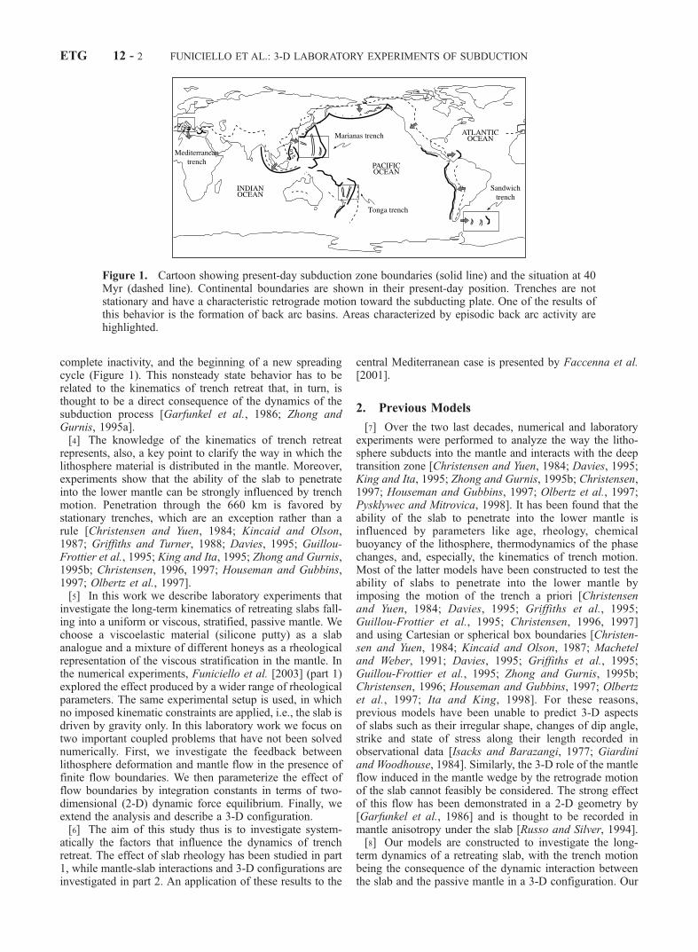
Figure 1. Cartoon showing present-day subduction zone boundaries (solid line) and the situation at 40Myr (dashed line). Continental boundaries are shown in their present-day position. Trenches are notstationary and have a characteristic retrograde motion toward the subducting plate. One of the results ofthis behavior is the formation of back arc basins. Areas characterized by episodic back arc activity arehighlighted.
ETG 12 - 2 FUNICIELLO ET AL.: 3-D LABORATORY EXPERIMENTS OF SUBDUCTION
models are inspired by the experimental work of Kincaidand Olson [1987]. As a new element we remove the lateralconstraints present in their experiments, and we enlarge ourinvestigation to the analysis of the evolution of the slab-mantle interaction in different 3-D configurations.
3. Model Setup
[9] Analysis of the parameters that control the oceaniclithosphere subduction highlights the difficulty of extractinggeneral rules [e.g., Jarrard, 1986]. Three main character-istics can be considered common to most of the subductionzones and they guide the design of our models.[10] The first feature common to most of the trenches is
their oceanward, retrograde motion in the hot spot referenceframe [Chase, 1978; Uyeda and Kanamori, 1979; Garfun-kel et al., 1986; Jarrard, 1986]. A large part of the Eurasianplate, from the Kurile to Indonesia trench, the North andSouth Americas (from the Aleutian to Chile trench), thewestern Indian plate (along the Tonga trench), and thePacific plate (along New Hebrides and Solomon trench)move toward their respective trenches, accommodating theprogressive closure of the Pacific Ocean [Garfunkel et al.,1986] (Figure 1). An exception to the retrograde behavior isfound along the Tethyan slab, where the action of Indianand Arabian indenters in Eurasia caused localized advance-ment of the trench [Le Pichon, 1982; Patriat and Achache,1984]. The Marianna trench has also been treated as anothercase of an ‘‘advancing’’ trench during the last 5 Myr [vander Hilst and Seno, 1993].[11] The second feature is the strong variability of the
lateral geometry of the slabs. The length of trenches isvariable (Figure 1). Some slabs, like the Scotia, the Car-ibbean, the Cascades, the Banda, the Tyrrhenian, and theAegean slab, are very narrow with a horizontal extent of theorder 100–300 km [see, e.g., Jarrard, 1986]. On thecontrary, others slabs, like the Andean and the Mariana-Izu-Bonin-Japan-Kurile-Kamchatka system, are very long,extending for a few thousands of kilometers. Moreover,single Benioff zones usually display very irregular shape,changing dips, strike, and state of stress along their lengthand forming arcs and cusp [Isacks and Barazangi, 1977;Giardini and Woodhouse, 1986; Yoshioka and Wortel,1995]. A striking example is the Chilean-Peru slab, whereflat portions border a steeper portion correlated with theBolivian orocline [Cahill and Isacks, 1992].[12] Finally, the majority of slabs have extended their
travel through the upper mantle and therefore interactedwith the 660-km discontinuity [e.g., Uyeda and Kanamori,1979]. The 660-km discontinuity is attributed to the phasetransition from b spinel to perovskite and magnesiowustite[e.g., Bina, 1991; Kirby et al., 1991]. It is accompanied by adensity increase (between 102 and 103 kg m�3, e.g., PREM)and a viscosity jump by a factor of 10–100). [Hager, 1984;Davies and Richards, 1992; King and Masters, 1992; Forteand Mitrovica, 1996; Mitrovica and Forte, 1997]. Tomo-graphic images and the analysis of deep earthquakes pro-vide additional information on the interaction between theslab and the phase boundary. In particular, tomographicimages indicate that some of these slabs penetrate into thelower mantle whereas others do not [van der Hilst et al.,1991; Li and Romanowicz, 1996; Grand et al., 1997;
Bijwaard et al., 1998]. Therefore the kinematics of trenchmotion of most slabs may be connected with the interactionproblem at the upper-lower mantle discontinuity.[13] These observations suggest to us that a meaningful
simulation of trench motion should take into account thefollowing: it should be able to retreat during its evolution(no kinematic constraints); it should consider 3-D complex-ities; and finally, the mature slab should interact with the660-km discontinuity. Our experiments are set up in thefollowing framework: (1) no external forces are imposed tothe system; (2) we assume a mantle with no trench-relativemotion as a reference frame; (3) the slab is fixed in the farfield of subduction; (4) the system is isothermal; and (5) thesystem does not include an overriding plate. A moredetailed explanation of these laboratory assumptions isnoted below.[14] 1. The system is driven only by the slab pull force
and by an equivalent ridge push force, implemented bylateral density contrast between plate and mantle. Noexternal kinematic boundary conditions are applied. Ourgoal is to capture the essence of the behavior of retreatingtrenches while removing all dynamic complexities.[15] 2. We are interested to isolate the effect of advection
inside the mantle produced by the subducting slab. Flow isonly generated by subduction, and we do not consider theeffect of global [Ricard et al., 1991] or local backgroundflow that is not generated by the subducting slab.[16] 3. This implies that the slab is attached in the far field
to the above reference frame.[17] 4. There are three consequences of this important
experimental constraint: One is that we consider an end-member model where the system is governed by thenegative buoyancy of the subducting slab alone; no positivebuoyancy from plumes is included. This negative buoyancyis implemented chemically. The second implication is thatthe density contrast of the slab is preserved during the wholesubduction process. This situation is equivalent to quasi-adiabatic conditions. Our velocity of the subduction processis much higher than 1 cm yr�1. Under these conditions, weeffectively neglect temperature changes during subduction[Wortel, 1982; Bunge et al., 1997]. The third consequence isthat we neglect the role of the endothermic phase changes atthe transition zone [Christensen and Yuen, 1985; Tackley etal., 1993; Pysklywec and Mitrovica, 1998]. The possibleeffect of impediment for the slab to penetrate into the lowermantle is here reproduced only by the increase in viscositywith depth.[18] 5. The system does not include an overriding plate.
This limitation has two consequences. The first conse-quence is that the plate boundary is weak since it has theviscosity of the upper mantle. Assumption influences therate of the process but has less influence on its generalbehaviour [King and Hager, 1990]. Therefore, if we con-sider the possible range of resistance given by the subduc-tion fault zone [Tichelaar and Ruff, 1993; Zhong andGurnis, 1994; Bunge et al., 1997; Toth and Gurnis,1998], the rate of plate subduction within the experimenthas to be considered as an upper bound [King and Hager,1990; Conrad and Hager, 1999]. The second consequenceis that the overriding plate is assumed to passively movewith the retreating trench. Therefore this experimentalsetting can be considered as appropriate for all the natural
FUNICIELLO ET AL.: 3-D LABORATORY EXPERIMENTS OF SUBDUCTION ETG 12 - 3
cases where the motion of the overriding plate toward thetrench is lower than the velocity of trench retreat (i.e., thewestern Pacific, the Mediterranean). For this reason ourmodel applies only to subduction systems where back arcbasins are present.[19] Following the approach used in previous analogue
studies, the rheology of the lithosphere, upper and lowermantle is approximated by linear viscous multilayer regions[Kincaid and Olson, 1987; Griffiths and Turner, 1988;Griffiths et al., 1995; Guillou-Frottier et al., 1995; Fac-cenna et al., 1996; Becker et al., 1999]. The analoguematerials, a silicone putty-honey composite, are selected
to scale to the slab-mantle system, as described by Fac-cenna et al., [1999]. A lower mantle layer has been added asa new feature. Silicone putty is a viscoelastic material. Forthe applied experimental strain rate the silicone putty can beconsidered as a quasi-Newtonian fluid where stressincreases linearly with strain rate [Weijermars, 1986]. It iscomposed of a pure polymeric substrate (polidimethylsilox-ane-PDMS) with galena and barium sulphate powder tovary both density and viscosity. The upper mantle has beenmodeled by honey, which is a Newtonian low-viscosityfluid (Table 1). The increase in viscosity in the lower mantlehas been reproduced by a mixture of pure honey and whitesugar prepared below the crystallization temperature. Theviscosity and density of each layer are constant and areconsidered as average effective values. The viscosity ratiobetween the slab (hl) and the upper mantle (hum) is variedbetween 350 and 1000, and the viscosity ratio betweenupper and lower mantle (hlm) is varied between 1 andinfinite. Viscosity ratios hl/hum and hum/hlm in nature areassumed to range between 102 and 103 and 10 and 100,respectively [Hager, 1984; Davies and Richards, 1992;King and Masters, 1992; Forte and Mitrovica, 1996;Mitrovica and Forte, 1997].[20] The multilayered system is arranged in a rectangular
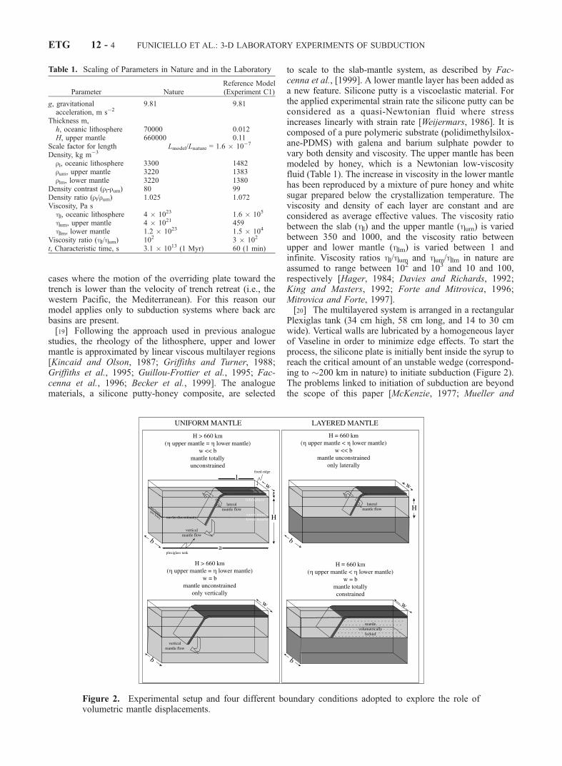
Plexiglas tank (34 cm high, 58 cm long, and 14 to 30 cmwide). Vertical walls are lubricated by a homogeneous layerof Vaseline in order to minimize edge effects. To start theprocess, the silicone plate is initially bent inside the syrup toreach the critical amount of an unstable wedge (correspond-ing to �200 km in nature) to initiate subduction (Figure 2).The problems linked to initiation of subduction are beyondthe scope of this paper [McKenzie, 1977; Mueller and
Table 1. Scaling of Parameters in Nature and in the Laboratory
Parameter NatureReference Model(Experiment C1)
g, gravitationalacceleration, m s�2
9.81 9.81
Thickness m,h, oceanic lithosphere 70000 0.012H, upper mantle 660000 0.11
Scale factor for length Lmodel/Lnature = 1.6 � 10�7
Density, kg m�3
rl, oceanic lithosphere 3300 1482rum, upper mantle 3220 1383rlm, lower mantle 3220 1380
Density contrast (rl-rum) 80 99Density ratio (rl/rum) 1.025 1.072Viscosity, Pa shl, oceanic lithosphere 4 � 1023 1.6 � 105
hum, upper mantle 4 � 1021 459hlm, lower mantle 1.2 � 1023 1.5 � 104
Viscosity ratio (hl/hum) 102 3 � 102
t, Characteristic time, s 3.1 � 1013 (1 Myr) 60 (1 min)
Figure 2. Experimental setup and four different boundary conditions adopted to explore the role ofvolumetric mantle displacements.
ETG 12 - 4 FUNICIELLO ET AL.: 3-D LABORATORY EXPERIMENTS OF SUBDUCTION
Phillips, 1991; Ericksson and Arkani-Hamed, 1993; Fac-cenna et al., 1999; Regenauer-Lieb et al., 2001].[21] The models are constructed using geometric and
dynamic similarity criteria of Davy and Cobbold [1991]and Faccenna et al. [1999]. Parameters and values fornature and the experimental system are listed in Table 1.[22] A total number of 50 different experiments were
performed using variable combinations of thickness, vis-cosities, densities of the slab and mantle and differentboundary conditions. Experiments were performed 2–6times to ensure reproducibility. Each experiment was moni-tored using a sequence of photographs taken in timeintervals (from 1 to 4 min) in the lateral and top view.Trench retreat and dip of the slab were measured usingimage-processing tools. The presence of tracers in themantle allowed us to define the behavior of volumetricmantle displacements identifying the geometry of inducedstreamlines and their evolution in time.
4. Assessment of Forces
[23] Many authors have analyzed the forces acting on theslab during the subduction process [Forsyth and Uyeda,1975; Chapple and Tullis, 1977; McKenzie, 1977; Davies,1980; Conrad and Hager, 1999] assuming steady stateconditions. In a dynamic setting, the absolute magnitudeand interaction between these forces is still poorly under-stood. An analytical assessment of forces acting on adynamically retreating slab is not feasible on the basis ofour present knowledge of slab dynamics. Here we presentthe following approach: first, we begin by reviewing steadystate conditions in the subduction process in a 2-D dip-parallel cross section through the slab. Next, we sum thedynamic forces expected in the retreating setting.
4.1. Review of Forces With a Fixed Trench
4.1.1. Driving Forces4.1.1.1. Fsp Slab Pull Force[24] A mature oceanic lithosphere is gravitationally unsta-
ble with respect to the underlying mantle. After formation ofan initial instability, the density contrast between the oce-anic lithosphere and the mantle becomes the main engine ofthe subduction.[25] The force per unit length due to the sinking slab, Fsp,
may be expressed as [McKenzie, 1977]
Fsp ¼ �rgzh; ð1Þ
where �r is the density contrast between lithosphere (rl)and mantle (rm), g is the acceleration due to gravity, and zand h are the depth and the thickness of the slab,respectively. The density contrast is not constant butdepends on the age of the oceanic lithosphere and on thephase changes that occur in the slab during the subductionprocess [e.g., Vlaar and Wortel, 1976; Turcotte andSchubert, 1982].[26] In the experimental system thermal aging of the
oceanic lithosphere is reproduced using chemistry byimposing a density contrast between the slab and themantle. In particular, we model lithosphere denser thanthe mantle with �r ranging between 50 and 100 kg m�3.As discussed, the initial density contrast is assumed to be
preserved during the entire subduction. In our experimentsFsp is the main force that drives subduction. Its valueincreases with depth and reaches 4.6 � 1013 N m�1 for660 km depth. This value is in agreement with the publishedvalues in the literature [McKenzie, 1977; Davies, 1980;Turcotte and Schubert, 1982].4.1.1.2. Frp Ridge Push Force[27] Mass conservation requires a balance between con-
sumption and plate generation. The horizontal force due toridge push, Frp, can be simplified assuming the thickness (h)and the density (rl) constant over the plate [McKenzie,1977] as
Frp ¼ �rgh
2
2
; ð2Þ
where �r is the density contrast between lithosphere (rl)and mantle (rm) and g is the acceleration due to gravity.[28] In our laboratory experiments a force similar to ridge
push arises as an initial condition. This force is due to thedensity contrast between lighter honey (the mantle) juxta-posed against the denser silicone putty (the lithosphere). Itsvalue is constant throughout the experiment. For a platewith h of 1.2 cm and �r of 100 kg m�3 in a natural gravityfield (gmodel = gnature) Frp is equal to 0.07 N m�1. This valuecorresponds, in nature, to 1.9 � 1012 N m�1. This result isin agreement with published estimates of the ridge pushforce, which vary between 3 and 7 � 1012 N m�1 [Parsonsand Richter, 1980; Toth and Gurnis, 1998]. The value of theFrp is low compared to Fsp.4.1.2. Resisting Forces4.1.2.1. Rb Slab-Bending Force[29] The force necessary to bend the plate at a trench
represents, in the mature stages of subduction, the mainresisting force controlling the subduction process [McKen-zie, 1977; Houseman and Gubbins, 1997; Becker et al.,1999; Conrad and Hager, 1999]. Following England andMcKenzie [1982], we assume that the elastic deformationover long time-scales can be incorporated in a viscoustheory. Hence the force necessary to bend a plate can beexpressed by developing the theory for the bending of aviscous plate of thickness h [Turcotte and Schubert, 1982].The order of magnitude of the viscous bending force is
Rb �uh3hlr3
; ð3Þ
where hl, h and r are the viscosity, the thickness, and theradius of curvature of the bending of the slab, respectively,and u is the subduction velocity.[30] For our linear viscous slab model the same relation-
ship holds when the slab bends at the 660-km discontinuity.In the dynamic experimental setup, steady state conditionsare, however, reached only after interaction with the 660-kmdiscontinuity. For this reason we postpone the analysis andthe comparison with previous models to section 6.4.1.2.2. Rf Resistance to Sliding Along theSubduction Fault[31] In analytical models the role of resistance to sliding
along a subduction fault is considered to be the principalfactor inhibiting the initiation of subduction [McKenzie,1977; Mueller and Phillips, 1991; Ericksson and Arkani-
FUNICIELLO ET AL.: 3-D LABORATORY EXPERIMENTS OF SUBDUCTION ETG 12 - 5
Hamed, 1993]. In the literature cited above, its value hasbeen estimated to be in the range of 4.8 � 1012 to 3 � 1013
N m�1. Toth and Gurnis [1998], using a numerical code,conclude that for subduction to initiate Rf should be lessthan 1.7 � 1012 N m�1. Zhong and Gurnis [1994] foundthat a shear friction value of between 15 and 30 MPa isrequired to match the dynamic topography at trench, con-sistent with values inferred by Tichelaar and Ruff [1993]from a frictional heating model of a subduction fault.[32] Recent numerical model results support the idea that
the subduction fault zone is particularly weak if a wetolivine rheology is assumed [Branlund et al., 2000, 2001;Regenauer-Lieb et al., 2001]. Finally, as previously dis-cussed, we assume that the fault has the same viscosity asthe upper mantle. Hence, in the force balance expression,the shear friction along this weak fault is of one order ofmagnitude less than that of Rb.4.1.2.3. Rs, Rn Shear and Normal Slab-MantleInterface Forces[33] Here we do not consider active mantle convection,
but instead, we investigate passive mantle flux driven by thesubducting plate. The displaced mantle exerts a viscousresistance on the subducting plate. For the case of a sta-tionary slab this force has been expressed in terms of cornerflow theory for a fixed dip [Turcotte and Schubert, 1982;Dvorkin et al., 1993]. In our case, a complexity is added dueto possibility of trench retreat and change of dip. For thepurpose of assessing the order of magnitude of the resist-ance as a function of the induced mantle flow we decom-pose it in terms of shear and normal components withoutsolving the full fluid dynamic problem.[34] The viscous shear slab-mantle interface force Rs is
defined as
Rs � hm u; ð4Þ
where hm is the mantle shear viscosity and u is thesubduction velocity. The shear resistance is directlyproportional to the viscosity of the mantle. For this reasonits importance increases in the lower mantle, where theviscosity is at least one order of magnitude larger than in theupper mantle [Hager, 1984; Davies and Richards, 1992;King and Masters, 1992; Forte and Mitrovica, 1996;Mitrovica and Forte, 1997]. Conrad and Hager [1999]estimate that at least 30% of the energy dissipated in theupper mantle is connected with this mechanism.[35] The normal component of slab motion Rn is set to
zero in previous steady state calculations, and therefore thisforce does not appear. In our case, however, some trench
normal energy is dissipated and Rn has to be evaluated. Infixed slab cases, Rn controls only the dip of the slab[Dvorkin et al., 1993; Turcotte and Schubert, 1982]. Thenegative and the positive value of the forces on the top andon the bottom of the descending slab, respectively, exert apressure torque that lifts the slab against the force of gravity.The sum of the lifting torque per unit length is defined, likethe shear force, as
Rn � hm u; ð5Þ
where the proportionality depends on slab dip.
4.2. Summary of Forces With Retreating Slab
[36] For a dynamically retreating slab, additional forcesarise owing to the mass redistribution within the convectingmantle. The corner flow approximation can no longer beused and a more complex approach is required. For aretreating slab, in fact, there will be an added componentto the nonhydrostatic pressure drop on the top and bottom ofthe slab that is associated with a substantial mass flux. The2-D situations have been analyzed numerically by Garfun-kel et al. [1986], who introduced a solid slab into apassively convecting uniform viscous fluid. Instantaneousstreamlines of the induced mantle flow show that for thecase of a retreating slab, the slab becomes part of theconvection cell and does not separate two independent cellsystems. That is, streamlines no longer run parallel to theslab as in the corner flow model. In fact, they cross the slabat a small but finite angle that is a function of the trenchretreat velocity. In this case, Rn is no longer negligible, andits intensity is a function of a characteristic length scale.[37] A more realistic 3-D configuration adds complexities
to the mantle flow pattern. To restore the hydrostaticequilibrium on both slab sides, it has been suggested[Luyendyk, 1970] that mantle material escapes into thecorner region between the slab and the overriding plate:this escape occurs from a region of high pressure to a regionof low pressure, with flow that has both dip-parallel andtrench-parallel components.[38] In a 3-D setting the in-plane bending of the slab is
another force that is caused by along strike lateral deforma-tion of the slab. This force is responsible for the shape ofarcs and/or cusps of several trenches.
5. Experimental Results
[39] Ten experimental setups (Table 2) with a total of 50experiments have been selected to describe: (1) the role
Table 2. Description of Materials and Parameters Used in the Selected Experiments
rl, g cm�3 rum, g cm�3 rlm, g cm�3 ml, Pa s mum, Pa s mlm, Pa s mlm/mum q, deg hl, cm hum, cm a, cm l, cm b, cm w, cm
A1 1.448 1.383 1.383 4.6 � 105 459 459 1 30 1.2 20 60 42 30 14B1 1.482 1.383 1.383 1.6 � 105 459 459 1 36 1.2 27 60 42 30 30B2 1.482 1.383 1.383 1.6 � 105 459 459 1(net) 33 1.2 11 56 42 30 30C1 1.482 1.383 ffi1.38 1.8 � 105 459 ffi1.5 � 104 32 59 1.2 11 56 42 30 14D1 1.482 1.383 ffi1.38 1.8 � 105 459 ffi4.6 � 103 10 32 1.2 11 56 42 30 30D2 1.482 1.383 - 1.6 � 105 459 1 1 31 1.2 11 56 42 14 14D3 1.482 1.383 ffi1.38 1.6 � 105 459 ffi1.5 � 104 32 30 1.2 11 56 42 14 14E1 1.487 1.383 ffi1.38 4.6 � 105 459 ffi1.5 � 104 32 20 1.2 11 56 42 14 14E2 1.452 1.383 - 1.8 � 105 459 1 1 55 1.2 11 56 42 14 14E3 1.482 1.383 ffi1.38 1.8 � 105 459 ffi1.5 � 104 32 39 1.5 11 56 42 30 30
ETG 12 - 6 FUNICIELLO ET AL.: 3-D LABORATORY EXPERIMENTS OF SUBDUCTION
played by volumetric mantle displacement and (2) the roleplayed by slab strength.
5.1. Observation of Volumetric Mantle Displacement
5.1.1. Upper Mantle Unconstrained Laterallyand Vertically[40] To define the degrees of freedom of the system, we
identify two different parameters: the ratio b/w between thebox width (b) and the plate width (w) for the lateral conditionand the ratio hum/hlm between the viscosities of the upper andthe lower mantle for the vertical condition (Figure 2).[41] Experiment A1 (Figure 3 and Table 2) is character-
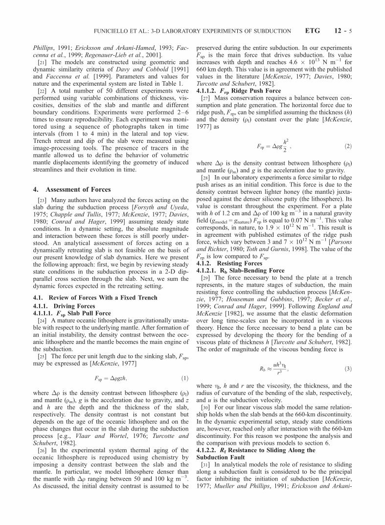
ized by a lateral aspect ratio b/w = 3 and by a viscosity ratiohum/hlm = 1. These conditions treat the case of an uppermantle that is volumetrically unconstrained (within thelimits of our laboratory approach). During the developmentof the experiment, the rate of trench retreat is fast and itincreases progressively in time with the amount of sub-ducted material. The dip of the slab also increases withtime reaching a steady state condition (�70�) in 5 Myr(Figure 3b). As the plate moves with a retrograde motion, anormal pressure force drives a poloidal fluid motion in theupper mantle. These mantle fluxes are directed from theregion of high-pressure to the region of low pressure and inthe horizontal plane they are directed toward and around theretreating trench (Figure 4a). The majority of fluid defor-mation occurs in a localized region extending 600 km onboth sides of the plate. During the entire process the trenchpreserves its straight shape.
5.1.2. Upper Mantle Unconstrained Only Vertically[42] Experiment B1 (Figure 5 and Table 2) is character-
ized by a lateral aspect ratio b/w = 1 and by a viscosity ratiohum/hlm = 1. Under these conditions the upper mantle isunconstrained only in the vertical direction. In this case therate of trench retreat and the velocity of slab also increaseprogressively in time with the increase of subducted mate-rial. The rate is slower than in the case described in section5.1.1, and the slab reaches a near-vertical dip in <20 Myr(Figure 5b). Subsequently, the laboratory limitationimposed by the bottom of the box causes a divergence fromthis behavior. The slab progressively shallows and decreasesits rate of descent. The laterally constrained boundarycondition imposes a mantle pressure, induced by the retro-grade motion, that directs mantle flow below the tip of theslab forming a shallow angle with the subducted lithosphere(Figure 4b). The trench preserves its straight shape duringthe entire process.[43] Experiment B2 (Table 2) is similar to B1 but the
upper-lower mantle discontinuity is represented by a 1 cm2
wide mesh net. This ensures circulation in the whole(laboratory) mantle but inhibits the possibility of slabpenetration into the lower mantle. The slab behavior issimilar to the previous case, accelerating exponentially andincreasing its dip to reach an angle of 90� during its descentinto the upper mantle. When the leading edge touches thenet, the trench retreat velocity is halved. The trench pre-serves its linear shape, and retreats at constant rate while theslab dip keeps a steady state value of 90�.
Figure 3. (a) Lateral view of four stages of evolution of the experiment A1. This experiment ischaracterized by an unconstrained upper mantle with respect to the horizontal and vertical directions. (b)Plot of the amount of trench retreat and dip versus time. The arrow indicates the time of interaction withthe 660-km discontinuity. Hereafter 1 min and 1 cm in the experiment correspond to 1 Myr and 60 km innature, respectively.
FUNICIELLO ET AL.: 3-D LABORATORY EXPERIMENTS OF SUBDUCTION ETG 12 - 7

5.1.3. Upper Mantle Unconstrained Only Laterally[44] In the next set of experiments we test the behavior of
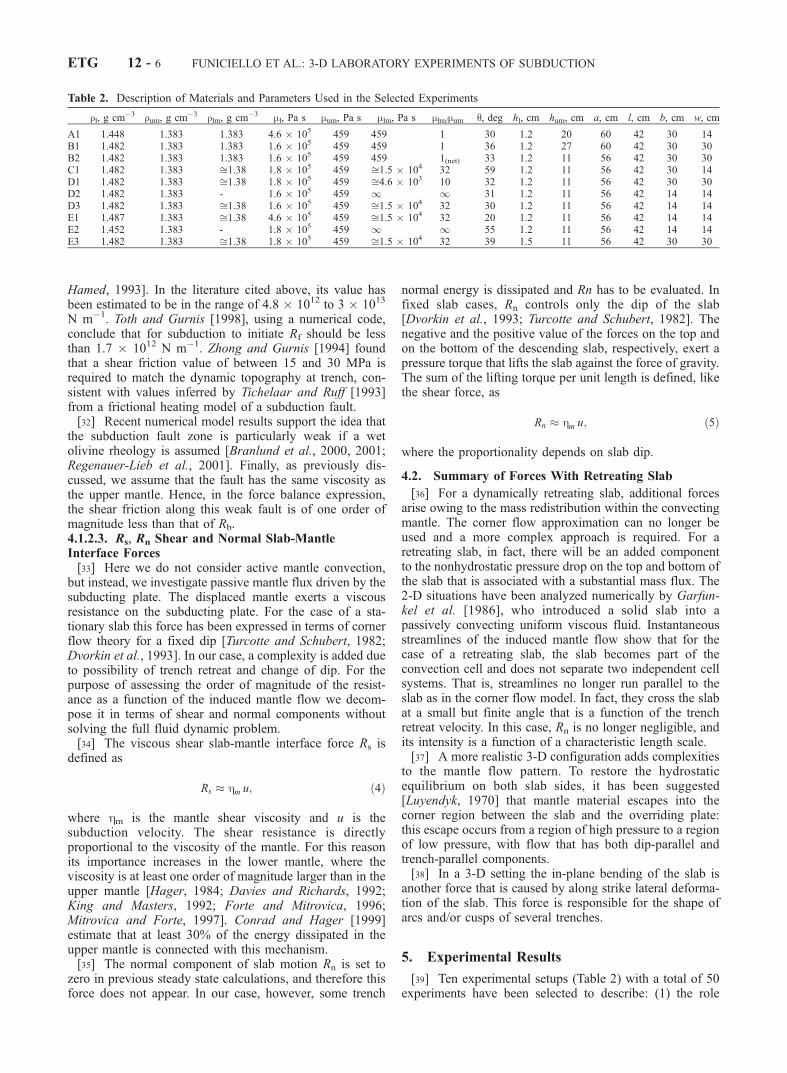
a subducting slab that is unconfined only in the lateraldirection. In comparison with previous experiments, thewidth of the box is doubled. This configuration can beadapted to areas where the slab is not continuous as in theScotia arc, Caribbean, Tonga. In the experiment C1 (Figure6 and Table 2), as in the experiment A1, the subduction
starts by increasing trench retreat velocity and dip andquickly reaches the bottom of the upper mantle (after 9Myr) with a steep dip (�70�). The tip of the slab folds anddeforms when the slab interacts with the 660-km disconti-nuity and the trend of subduction changes. The trenchretreats with a new steady state trend after 2 Myr ofslowing. The trench preserves its cylindrical shape (i.e.,no top view arc) at the surface (Figure 7). Surface mantle
Figure 5. (a) Lateral view of four stages of evolution of the experiment B1. This experiment ischaracterized by an upper mantle unconstrained only vertically. (b) Plot of amount of trench retreat anddip versus time.
Figure 4. Top and lateral view of two experiments to show the horizontal and the vertical componentsof the 3-D mantle flow pattern. (a) Toroidal mantle flow pattern observed when the slab hits the 660-kmdiscontinuity. Trench-parallel components are in direct juxtaposition to trench normal components. (b)Poloidal mantle flow component with a dip-parallel component. Because of the retreating motion of thetrench, the poloidal streamlines have a shallow angle with respect to the subducted lithosphere. Garfunkelet al. [1986] described the same distribution of instantaneous streamlines. The component in Figure 4a isthe most important when the slab falls into the upper mantle While the component in Figure 4b becomesdominant when the edge of the slab reaches a more viscous layer in the deep mantle.
ETG 12 - 8 FUNICIELLO ET AL.: 3-D LABORATORY EXPERIMENTS OF SUBDUCTION
material shows flow lines diverging laterally outside theslab/lithosphere sides and progressively converging towardthe trench.5.1.4. Upper Mantle Totally Constrained[45] This group of experiments is characterized by a
lateral aspect ratio b/w = 1 and different viscosity ratiosbetween upper and lower mantle for different experimentalruns (Figure 8 and Table 2). Experiments D1, D2, and D3,are characterized by viscosity ratio hum/hlm equal to 10, 30,and infinite (i.e., depth of the box restricted to the uppermantle), respectively (Table 2). The behavior of the slabduring its upper mantle dive is similar to the B1 case: theslab falls into the upper mantle accelerating exponentially(Figures 8a (stages 1–3) and 8b) and its dip increases up toa maximum angle of 72�, 65�, and 54� for the experimentsD1, D2, and D3, respectively. When the slab approaches theupper-lower mantle transition, at an equivalent depth of�500 km, its dip decreases by 5�–10�, while the slabdecelerates (Figures 8a (stages 4–5) and 8b).[46] Subsequently, the slab touches the transition zone,
and the trench migration halts for �5 Myr. The trench starts
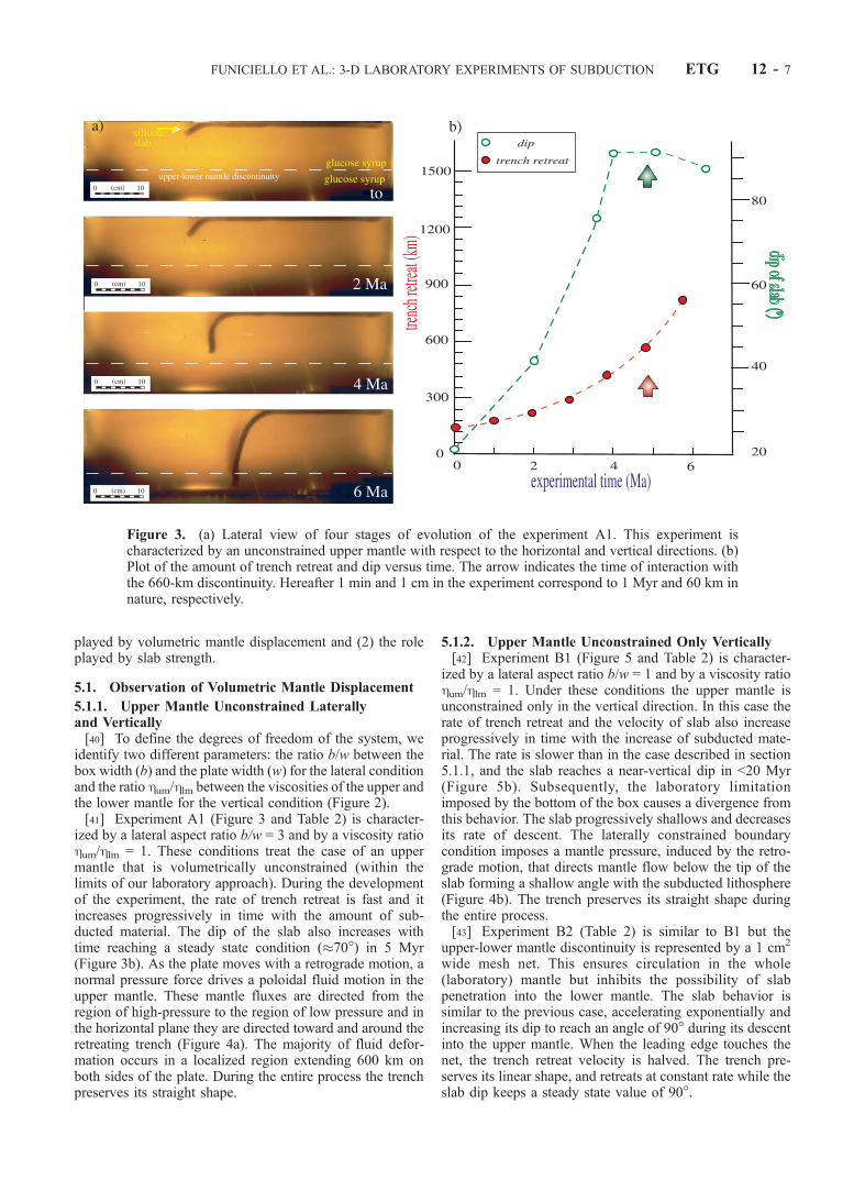
Figure 7. Top view of two different experiments characterized by a viscosity jump at the upper/lowermantle discontinuity. Consequently, the system is in both cases vertically constrained. The shape of thetrench is sensitive to the lateral boundary conditions when the slab reaches the 660-km discontinuity. (a)If the system is laterally confined, the slab forms an arc (in top view) after the interaction with the lowermantle discontinuity. (b) The trench preserves its cylindrical shape at surface during the whole process ifthe system is laterally unconfined.
Figure 6. Plot of experiment C1 (mantle unconstrainedonly laterally) in terms of the amount of trench retreat anddip versus time.
FUNICIELLO ET AL.: 3-D LABORATORY EXPERIMENTS OF SUBDUCTION ETG 12 - 9
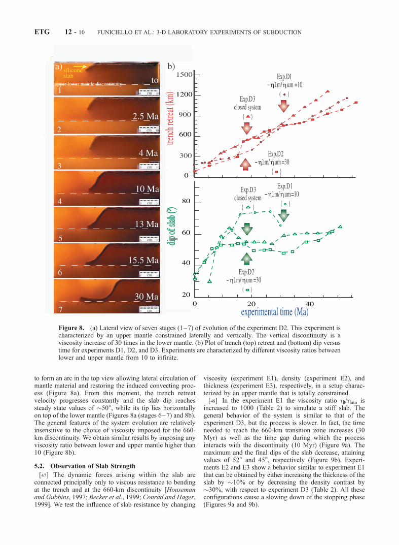
to form an arc in the top view allowing lateral circulation ofmantle material and restoring the induced convecting proc-ess (Figure 8a). From this moment, the trench retreatvelocity progresses constantly and the slab dip reachessteady state values of �50�, while its tip lies horizontallyon top of the lower mantle (Figures 8a (stages 6–7) and 8b).The general features of the system evolution are relativelyinsensitive to the choice of viscosity imposed for the 660-km discontinuity. We obtain similar results by imposing anyviscosity ratio between lower and upper mantle higher than10 (Figure 8b).
5.2. Observation of Slab Strength
[47] The dynamic forces arising within the slab areconnected principally only to viscous resistance to bendingat the trench and at the 660-km discontinuity [Housemanand Gubbins, 1997; Becker et al., 1999; Conrad and Hager,1999]. We test the influence of slab resistance by changing
viscosity (experiment E1), density (experiment E2), andthickness (experiment E3), respectively, in a setup charac-terized by an upper mantle that is totally constrained.[48] In the experiment E1 the viscosity ratio hl/hum is
increased to 1000 (Table 2) to simulate a stiff slab. Thegeneral behavior of the system is similar to that of theexperiment D3, but the process is slower. In fact, the timeneeded to reach the 660-km transition zone increases (30Myr) as well as the time gap during which the processinteracts with the discontinuity (10 Myr) (Figure 9a). Themaximum and the final dips of the slab decrease, attainingvalues of 52� and 45�, respectively (Figure 9b). Experi-ments E2 and E3 show a behavior similar to experiment E1that can be obtained by either increasing the thickness of theslab by �10% or by decreasing the density contrast by�30%, with respect to experiment D3 (Table 2). All theseconfigurations cause a slowing down of the stopping phase(Figures 9a and 9b).
Figure 8. (a) Lateral view of seven stages (1–7) of evolution of the experiment D2. This experiment ischaracterized by an upper mantle constrained laterally and vertically. The vertical discontinuity is aviscosity increase of 30 times in the lower mantle. (b) Plot of trench (top) retreat and (bottom) dip versustime for experiments D1, D2, and D3. Experiments are characterized by different viscosity ratios betweenlower and upper mantle from 10 to infinite.
ETG 12 - 10 FUNICIELLO ET AL.: 3-D LABORATORY EXPERIMENTS OF SUBDUCTION
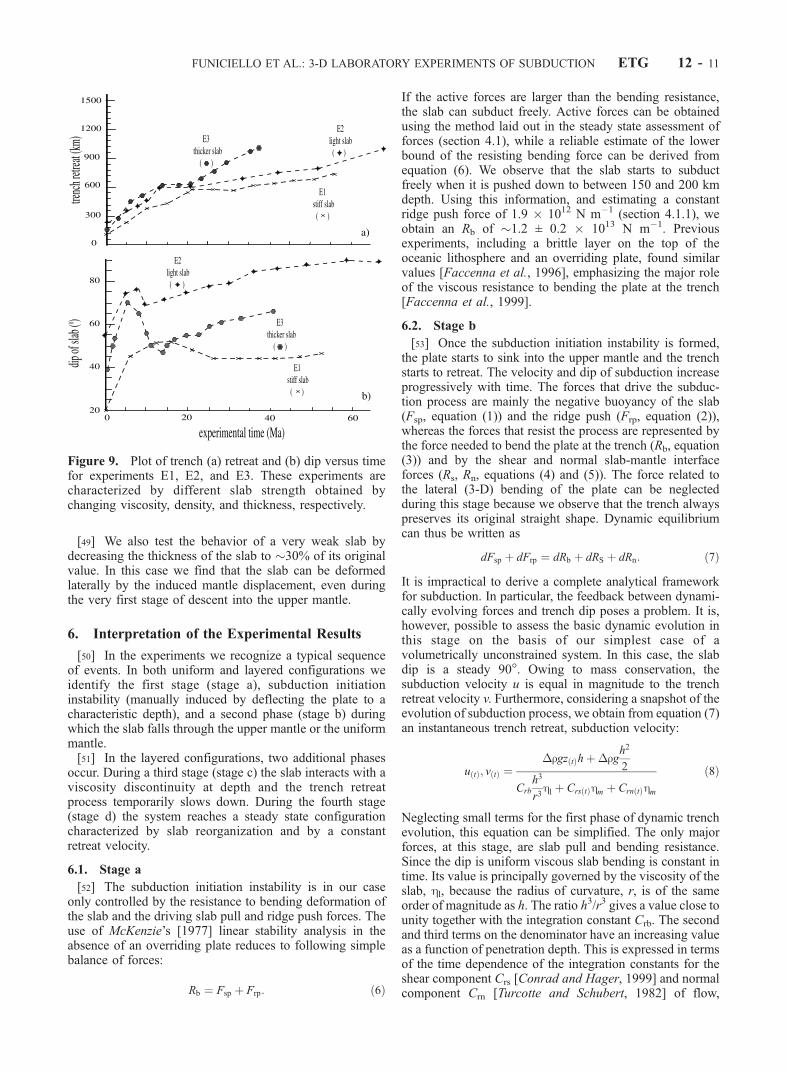
[49] We also test the behavior of a very weak slab bydecreasing the thickness of the slab to �30% of its originalvalue. In this case we find that the slab can be deformedlaterally by the induced mantle displacement, even duringthe very first stage of descent into the upper mantle.
6. Interpretation of the Experimental Results
[50] In the experiments we recognize a typical sequenceof events. In both uniform and layered configurations weidentify the first stage (stage a), subduction initiationinstability (manually induced by deflecting the plate to acharacteristic depth), and a second phase (stage b) duringwhich the slab falls through the upper mantle or the uniformmantle.[51] In the layered configurations, two additional phases
occur. During a third stage (stage c) the slab interacts with aviscosity discontinuity at depth and the trench retreatprocess temporarily slows down. During the fourth stage(stage d) the system reaches a steady state configurationcharacterized by slab reorganization and by a constantretreat velocity.
6.1. Stage a
[52] The subduction initiation instability is in our caseonly controlled by the resistance to bending deformation ofthe slab and the driving slab pull and ridge push forces. Theuse of McKenzie’s [1977] linear stability analysis in theabsence of an overriding plate reduces to following simplebalance of forces:
Rb ¼ Fsp þ Frp: ð6Þ
If the active forces are larger than the bending resistance,the slab can subduct freely. Active forces can be obtainedusing the method laid out in the steady state assessment offorces (section 4.1), while a reliable estimate of the lowerbound of the resisting bending force can be derived fromequation (6). We observe that the slab starts to subductfreely when it is pushed down to between 150 and 200 kmdepth. Using this information, and estimating a constantridge push force of 1.9 � 1012 N m�1 (section 4.1.1), weobtain an Rb of �1.2 ± 0.2 � 1013 N m�1. Previousexperiments, including a brittle layer on the top of theoceanic lithosphere and an overriding plate, found similarvalues [Faccenna et al., 1996], emphasizing the major roleof the viscous resistance to bending the plate at the trench[Faccenna et al., 1999].
6.2. Stage b
[53] Once the subduction initiation instability is formed,the plate starts to sink into the upper mantle and the trenchstarts to retreat. The velocity and dip of subduction increaseprogressively with time. The forces that drive the subduc-tion process are mainly the negative buoyancy of the slab(Fsp, equation (1)) and the ridge push (Frp, equation (2)),whereas the forces that resist the process are represented bythe force needed to bend the plate at the trench (Rb, equation(3)) and by the shear and normal slab-mantle interfaceforces (Rs, Rn, equations (4) and (5)). The force related tothe lateral (3-D) bending of the plate can be neglectedduring this stage because we observe that the trench alwayspreserves its original straight shape. Dynamic equilibriumcan thus be written as
dFsp þ dFrp ¼ dRb þ dRS þ dRn: ð7Þ
It is impractical to derive a complete analytical frameworkfor subduction. In particular, the feedback between dynami-cally evolving forces and trench dip poses a problem. It is,however, possible to assess the basic dynamic evolution inthis stage on the basis of our simplest case of avolumetrically unconstrained system. In this case, the slabdip is a steady 90�. Owing to mass conservation, thesubduction velocity u is equal in magnitude to the trenchretreat velocity v. Furthermore, considering a snapshot of theevolution of subduction process, we obtain from equation (7)an instantaneous trench retreat, subduction velocity:
u tð Þ; v tð Þ ¼�rgz tð Þhþ�rg
h2
2
Crb
h3
r3hl þ Crs tð Þhm þ Crn tð Þhm
ð8Þ
Neglecting small terms for the first phase of dynamic trenchevolution, this equation can be simplified. The only majorforces, at this stage, are slab pull and bending resistance.Since the dip is uniform viscous slab bending is constant intime. Its value is principally governed by the viscosity of theslab, hl, because the radius of curvature, r, is of the sameorder of magnitude as h. The ratio h3/r3 gives a value close tounity together with the integration constant Crb. The secondand third terms on the denominator have an increasing valueas a function of penetration depth. This is expressed in termsof the time dependence of the integration constants for theshear component Crs [Conrad and Hager, 1999] and normalcomponent Crn [Turcotte and Schubert, 1982] of flow,
Figure 9. Plot of trench (a) retreat and (b) dip versus timefor experiments E1, E2, and E3. These experiments arecharacterized by different slab strength obtained bychanging viscosity, density, and thickness, respectively.
FUNICIELLO ET AL.: 3-D LABORATORY EXPERIMENTS OF SUBDUCTION ETG 12 - 11

respectively. These terms are also governed by viscosityvalues. However, the mantle viscosity hm is �2 orders ofmagnitude smaller than that of the slab hl. For this reason themantle resistance can be treated as negligible in this phase. Inthe numerator, the second term that corresponds to ridgepush, Rp, can also be neglected because it is one order ofmagnitude lower than slab pull. Equation (8) now becomes
u tð Þ; v tð Þ ��rgz tð Þh
Crb
h3
r3hl
: ð9Þ
Since u(t) = dx(t)/dt, v(t) = dz(t)/dt, equation (9) can then beintegrated [Becker et al., 1999] to yield
z tð Þ; x tð Þ � z0 exp C�rgr3
h2hlt
� �: ð10Þ
Equation (10) is used to fit the experimental data (Figure 10).In this case, the integration constant C is a fixed parameterand both the radius of curvature and induced initial depth ofsubduction z0 are observables.[54] For the family of experiments with laterally uncon-
strained convection systems, a good fit is obtained using avalue of C = 1.2. On the contrary, experiments done with
laterally confined boundary conditions yield an integrationof C = 0.2. Similar results have been obtained for a laterallyclosed system using the numerical experiments of Becker etal. [1999]. C appears to be independent on the way themantle is stratified and it does not depend on the rheologyof the slab.[55] Although this provides a satisfactory first-order
approach, the kinematic consequence of the balance of thedynamic equilibrium between Fsp and Rb is always aretrograde migration of the descending slab. This retrogrademotion of the slab produces a significant mass flux in themantle [Garfunkel et al., 1986], which has to be discussed.The mantle flow is directed from the region of high pressureto the region of low pressure (Figure 4). The interactionbetween the mantle induced flow and the slab depends uponthe strength of the slab, its viscous coupling with the mantleand velocity boundary conditions.[56] A striking example of this interaction is observed
before the slab hits the 660-km discontinuity. In stage b wealways note that �150 km above the mantle discontinuity,the slab appears to sense it and decreases its dip by 10�–20�while its retreat velocity continues to increase (Figures 3, 5,6, and 8). We interpret this change in the slab behavior as adirect consequence of enhanced mass flux concentrated inthe window between the slab tip and the upper/lower mantle
Figure 10. Best fit of the experimental data with the amount of trench retreat vs. time during thedescent of the slab into the mantle. (a) Exponential curves obtained during the dynamic free fall stagefitted by equation (10). (b) Linear fits obtained after the interaction with the 660-km discontinuity usingequation (12).
ETG 12 - 12 FUNICIELLO ET AL.: 3-D LABORATORY EXPERIMENTS OF SUBDUCTION
discontinuity. The mantle circulation is confined in a criticalnarrow channel that divides the upper mantle reservoir intwo distinct parts. The high pressure behind the slab causesshallowing of the slab as predicted by Luyendyk [1970],Garfunkel et al. [1986], and Dvorkin et al. [1993] and itdeforms the plate as it approaches the deep discontinuity(Figure 8a, stage 4).[57] This interpretation is confirmed by our experimental
run using a net at the same depth of the upper-lower mantlediscontinuity. The netting allows mantle circulation whileinhibiting slab penetration. This experiment shows a steepslab during the whole process as the mantle can freelycirculate thought the net. The influence of mantle flow isobserved in all the layered systems, but it is more pro-nounced for laterally constrained systems.
6.3. Stage c
[58] The slab reaches its minimum dip, and the subduc-tion process is temporarily delayed for �5–10 Myr whenthe slab interacts with the mantle discontinuity. The platethen bends at depth: in a laterally constrained system,bending at depth occurs only after the slab deforms hori-zontally into an arc shape, whereas in laterally uncon-strained systems, trench retreat halts for �5 Myr and thetrench preserves its straight linear shape (Figure 7).[59] This system evolution is a direct consequence of the
high viscosity of the lower mantle. Over the timescale of theexperiments, convection inside the lower viscosity layer isslow, and our slab does not penetrate into the lower mantle. Insuch a case, the slab obstructs the circulation of the uppermantle material. To restore the mantle circulation whileconserving mass, the material can only flow on the lateralsides. The time necessary for this process is a function of thelateral boundary conditions, the strength of the slab and themantle viscosity. As expected, the time gap is drasticallyreduced in the case of a laterally unconstrained slab/plate orfor a very weak slab/plate that can easily deform. Once thesystem reaches this new dynamic equilibrium, the slab startsto bend and lies down on the deep discontinuity, the dip of theslab increases and the trench resumes its retrograde motion.[60] This third stage, characterized by the ‘‘stop-and-go’’
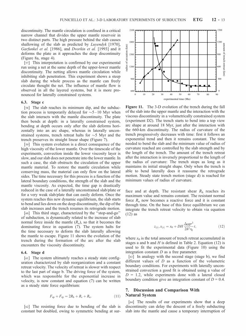
of subduction, is dynamically related to the increase of slabnormal force inside the mantle (Rn), so that it becomes thedominating force in equation (7). The system halts forthe time necessary to deform the slab laterally allowingthe mantle to escape. Figure 11 shows the evolution of thetrench during the formation of the arc after the slabencounters the viscosity discontinuity.
6.4. Stage d
[61] The system ultimately reaches a steady state config-uration characterized by slab reorganization and a constantretreat velocity. The velocity of retreat is slower with respectto the last part of stage b. The driving force of the system,which was responsible for the exponential increase invelocity, is now constant and equation (7) can be writtenas a steady state force equilibrium:
Fsp þ Frp ¼ 2Rb þ Rs þ Rn: ð11Þ
[62] The resisting force due to bending of the slab isconstant but doubled, owing to symmetric bending at sur-
face and at depth. The resistant shear Rb reaches itsmaximum value and remains constant. The resistant normalforce Rn now becomes a reactive force and it is constantthrough time. On the base of this force equilibrium we canintegrate the trench retreat velocity to obtain via equation(12) as
z tð Þ; x tð Þ ¼ x0 þ DH�rgr3
2h2hlt; ð12Þ
where x0 is the total amount of trench retreat accumulated instages a and b and H is defined in Table 2. Equation (12) isused to fit the experimental data (Figure 10) using theintegration constant D as a free parameter.[63] In analogy with the second stage (stage b), we find
different values of D as a function of the volumetricboundary conditions. For experiments with laterally uncon-strained convection a good fit is obtained using a value ofD = 1.2, while experiments done with a lateral closedboundary condition give an integration constant of D = 0.4.
7. Discussion and Comparison WithNatural System
[64] The results of our experiments show that a deepdiscontinuity can delay the descent of a freely subductingslab into the mantle and cause a temporary interruption of
Figure 11. The 3-D evolution of the trench during the fallof the slab into the upper mantle and the interaction with theviscous discontinuity in a volumetrically constrained system(experiment D2). The trench starts to bend into a top viewarc shape at around 18 Myr, just after the interaction withthe 660-km discontinuity. The radius of curvature of thetrench progressively decreases with time: first it follows anexponential trend and then it remains constant. The timeneeded to bend the slab and the minimum value of radius ofcurvature reached are controlled by the slab strength and bythe length of the trench. The amount of the trench retreatafter the interaction is inversely proportional to the length ofthe radius of curvature: The trench stops as long as itmaintains its initial straight shape. Only when the trench isable to bend laterally does it reassume the retrogrademotion. Steady state trench motion (stage d) is reached forminimum values of radius of curvature.
FUNICIELLO ET AL.: 3-D LABORATORY EXPERIMENTS OF SUBDUCTION ETG 12 - 13
its retrograde motion and a possible reorganization of theslab-mantle system. After initiation of subduction (stage a)the trench moves backward in three stages (stages b–d).Stage b is a dynamic phase of accelerated trench retreat thatoccurs during the ‘‘free’’ fall of the slab into the uppermantle. We have shown that this stage is primarily con-trolled by the resistance of the slab to bending at the trench.However, we obtain different results for lateral flow boun-dary conditions. The laterally open system shows a muchfaster retreat than the closed system. We have obtainedconsistent results with an integration constant of C = 1.2 foran open system versus 0.2 for a closed system. Stage b laststypically 6–30 Myr and ends when the slab interacts withthe 660-km discontinuity. A striking observation is thatstage b ceases when the slab reaches �150 km from thelower mantle discontinuity, and we believe this change isdue to accelerating mantle flow in the gap between slab and660-km discontinuity. Stage c is another dynamic phasecharacterized by the interaction of the slab, the deepdiscontinuity and induced mantle flow. The latter flow ofmantle material is the controlling factor in this phase. In avolumetrically locked upper mantle system, the slab andtrench retreat velocities drop significantly. After thisdynamic phase and reequilibration of mantle flow pathwaysstage d occurs. It is characterized by steady state trenchretreat with a velocity that is up to 2 times smaller than themaximum velocity recorded in stage b.[65] In comparison with the numerical results (part 1) we
have following conclusions. The dynamic acceleration stageb and the steady trench phase, stage d, are recorded in boththe numerical and experimental results. They can thereforebe considered a robust result of our experiments. Anintriguing difference between the numerical and the exper-imental results is evident in stage c between the dynamic‘‘free fall’’ and steady state trench retreat phases. This phaseis not recorded in the numerical results where the volumet-ric mantle flow is not present. This suggests to us that thestage c is strongly influenced by the volume flow into themantle.[66] It is important to note that even in the laterally
unconstrained laboratory experiments, which should beclosest to the numerical model, this intermittent phaseshows up as a less significant but still important process.In summary, we conclude that subduction cannot be treatedas a steady state process and that there are phases ofepisodicity embedded in the nature of mantle-lithosphereinteraction.[67] Another result from numerical and analogue experi-
ments is that a slab does not penetrate across the lowerdiscontinuity if kinematic boundary conditions are notimposed. This inference holds if the viscosity of the lowermantle is an order of magnitude larger than the upper mantleand the timescale of deformation is <30 Myr. Similar resultshave been obtained for kinematic boundary conditions[Davies, 1995; Guillou-Frottier et al., 1995; Christensen,1996] in which penetration only occurred 100 Myr after theinitiation of the process [Davies, 1995].[68] A primary test for the validity of our experiments is
to determine whether natural systems show the character-istic episodic behavior of trench retreat. Under the assump-tions of a one-to-one relation between back-arc spreadingand trench retreat we can test the observation of episodicity
of back arc extension/trench retreat. The direct comparisonbetween experiments and nature has been performed for thecentral Mediterranean region [Faccenna et al., 2001]. In thisarea two basins, the Liguro-Provencal and the Tyrrhenian,opened one after the other, with a pause of �5 Myr. We canextend the comparison to other cases of episodic back arcextension, although the available data set is not that accu-rate. Here we extend this model to the case of the Tongatrench with the South Fiji and Lau Basins and to theMariana trench with the Parece-Vela Basin and the MarianaTrough. Despite differences between these back arc sys-tems, such as the convergence velocity (ranging from 0–2cm yr�1 in the central Mediterranean to �10 cm yr�1 in thewest Pacific basins), the lateral dimension of the slab(ranging from 200–500 km in the Tyrrhenian slab to thethousands of kilometers for the Marianna and Tonga-Ker-madec slabs), some features appear to be common and canbe interpreted dynamically using our experimental results.For example, the life of these basins is never longer than 30Myr [Uyeda and Kanamori, 1979; Taylor and Karner,1983], and the phase between the two extensional episodesranges from 5 to 20 Myr [Hussong and Uyeda, 1981; Hall,1996; Ballance, 1999; Park et al., 1990]. These timescalesare of the same order of magnitude than those observed inthe laboratory. In addition, as observed in the experiments,in most of the cases the opening of the first back-arc basinoccurred soon after the initiation of subduction, while theslab was still plunging into the upper mantle [Jolivet et al.,1989; Rangin et al., 1990; Stern and Bloomer, 1992; Hall etal., 1995]. Finally, the closure of the first basin is associ-ated, in the experiments, with a decrease in the dip of theslab to a minimum value. This relationship possibly holdsalso for the case of the Japan Sea, where from 20 Ma[Isezaki, 1986; Jolivet et al., 1994] the former back arcspreading center became inactive while the slab attained ashallow dip of �40� [Isacks and Molnar, 1971].[69] Another observable is the seismic anisotropy that is
interpreted as indication of flow direction in the mantle[Russo and Silver, 1994]. Trench-parallel orientation of thefast polarization direction is preferentially found on theseaward side of trenches, while on the wedge side a trenchnormal component has been observed. A striking example ofthis behavior is recognizable beneath the Nazca plate alongthe Chilean-Peru slab [Russo and Silver, 1994]. In ourexperiments we find a similar trench-parallel trend in thewake of the retreating slab [see alsoButtles andOlson, 1998].
8. Conclusions
[70] The key aspect of the dynamics of trench retreat for agravity driven slab is governed by bending deformation andslab-mantle interactions. We have shown here that thissystem has a highly dynamic evolution with distinctlydifferent phases of deformation. We have classified twofamilies of dynamic results with different parameters ofintegration constants C and D. These families are catego-rized by the presence of open or closed boundary conditions.[71] A characteristic lateral length scale of 10 cm across
the slab, corresponding to �600 km in nature, is observedas the critical distance separating the closed from openboundary cases. Below this length scale the subducting slabfeels the effect of the boundary and is considered a closed
ETG 12 - 14 FUNICIELLO ET AL.: 3-D LABORATORY EXPERIMENTS OF SUBDUCTION
system. In our experiments, closed boundary conditioncases are more prone to episodicity. In the above compar-ison to nature we have discussed episodic behaviorobserved in Tonga, the Marianas the central Mediterraneancases. All of these cases are relevant to our closed labo-ratory system since the next subduction zone is closer than600 km away.
[72] Acknowledgments. We would like to thank Thorsten Becker andSaskia Goes, who improved the first draft of the manuscript. We also thankGabriele Morra for fruitful discussions and constructive comments. Thepaper benefited from the constructive reviews of Michel Manga and NormSleep. We are particularly grateful to the associate editor Jerry Mitrovica forhis insightful comments and his revision. Agnes Ganivet is thanked for herkind assistance. This is publication 1235 of Institute of Geophysics, ETHZurich.
ReferencesBallance, P. F., Simplification of the southwest Pacific Neogene arcs: In-herited complexity and control by a retreating pole of rotation, in Con-tinental Tectonics, edited by C. MacNiocaill and P. D. Ryan, Geol. Soc.Spec. Publ., 164, 7–19, 1999.
Becker, T. W., C. Faccenna, R. J. O’Connell, and D. Giardini, The devel-opment of slabs in the upper mantle: Insights from numerical and labora-tory experiments, J. Geophys. Res., 104, 15,207–15,226, 1999.
Bevis, M., et al., Geodetic observations of very rapid convergence andback-arc extension at Tonga arc, Nature, 374, 249–251, 1995.
Bijwaard, H., W. Spakman, and E. R. Engdahl, Closing the gap betweenregional and global travel time tomography, J. Geophys. Res., 103,30,055–30,078, 1998.
Bina, C. R., Mantle discontinuities, Rev. Geophys., 29, 783–793, 1991.Branlund, J., K. Regenauer-Lieb, and D. Yuen, Fast ductile failure of pas-sive margins from sediment loading, Geophys. Res. Lett., 27, 1989–1993, 2000.
Branlund, J., K. Regenauer-Lieb, and D. Yuen, Weak zone formation forinitiating subduction from thermo-mechanical feedback of low-tempera-ture plasticity, Earth Planet. Sci. Lett., 190, 237–250, 2001.
Bunge, H. P., M. A. Richards, and J. R. Baumgardner, A sensitivity study ofthree-dimensional spherical mantle convection at 108 Rayleigh number:Effects of depth-dependent viscosity, heating mode, and endothermicphase change, J. Geophys. Res., 102, 11,991–12,007, 1997.
Buttles, J., and P. Olson, A laboratory model of subduction zone anisotropy,Earth Planet. Sci. Lett., 164, 245–262, 1998.
Cahill, T., and B. L. Isacks, Seismicity and shape of the subducted Nazcaplate, J. Geophys. Res., 97, 17,503–17,529, 1992.
Chapple, W. M., and T. E. Tullis, Evaluation of the forces that drive theplates, J. Geophys. Res., 82, 1867–1984, 1977.
Chase, C. G., Plate kinematics: The Americas, East Africa and the rest ofthe world, Earth Planet. Sci. Lett., 37, 357–368, 1978.
Christensen, U. R., The influence of trench migration on slab penetrationinto the lower mantle, Earth Planet. Sci. Lett., 140, 27–39, 1996.
Christensen, U. R., Influence of chemical buoyancy on the dynamics of slabin the transition zone, J. Geophys. Res., 102, 22,435–22,443, 1997.
Christensen, U. R., and D. Yuen, The interaction of the subducting litho-spheric slab with a chemical or phase boundary, J. Geophys. Res., 89,4389–4402, 1984.
Christensen, U. R., and D. Yuen, Layered convection induced by phasechanges, J. Geophys. Res., 90, 10,291–10,300, 1985.
Conrad, C. P., and B. H. Hager, Effects of plate bending and fault strengthat subduction zones on plate dynamics, J. Geophys. Res., 104, 17,551–17,571, 1999.
Davies, G. F., Mechanics of subducted lithosphere, J. Geophys. Res., 85,6304–6318, 1980.
Davies, G. F., Penetration of plates and plumes through the mantle transi-tion zone, Earth Planet. Sci. Lett., 133, 507–516, 1995.
Davies, G. F., and G. F. Richards, Mantle convection, J. Geol., 100, 151–206, 1992.
Davy, P., and P. R. Cobbold, Experiments on shortening of a 4-layer con-tinental Lithosphere, Tectonophysics, 188, 1–25, 1991.
DeMets, C., R. G. Gordon, D. F. Argus, and S. Stein, Current plate motions,Geophys J. Int., 101, 425–478, 1990.
Dewey, J. F., Episodicity, sequence and style at convercent plate bound-aries, in The Continental Crust and Its Mineral Deposits, edited by D. W.Strangway, Geol. Assoc. Can. Spec. Pap., 20, 553–573, 1980.
Dvorkin, J., A. Nur, G. Mavko, and A. Z. Ben, Narrow subducting slabsand the origin of backarc basins, Tectonophysics, 227, 63–79, 1993.
England, P., and D. P. McKenzie, A thin viscous sheet model for continen-tal deformation, Geophys. J. R. Astron. Soc., 70, 295–321, 1982.
Ericksson, S. G., and J. Arkani-Hamed, Subduction initiation at passivemargins: The Scotian Basin, eastern Canada as a potential example,Tectonics, 12, 678–687, 1993.
Faccenna, C., P. Davy, J. P. Brun, R. Funiciello, D. Giardini, M. Mattei, andT. Nalpas, The dynamic of backarc basins: An experimental approach tothe opening of the Tyrrhenian Sea, Geophys. J. Int., 126, 781–795, 1996.
Faccenna, C., D. Giardini, P. Davy, and A. Argentieri, Initiation of subduc-tion at Atlantic-type margins: Insights from laboratory experiments,J. Geophys. Res., 104, 2749–2766, 1999.
Faccenna, C., F. Funiciello, D. Giardini, and P. Lucente, Episodic back-arcextension during restricted mantle convection in the central Mediterra-nean, Earth Planet. Sci. Lett., 187, 105–116, 2001.
Forsyth, D., and S. Uyeda, On the relative importance of the driving forcesof plate motion, Geophys. J. R. Astron. Soc., 43, 163–200, 1975.
Forte, A. M., and J. X. Mitrovica, New inferences of mantle viscosity fromjoint inversion of long-wavelength mantle convection and post glacialrebound data, Geophys. Res. Lett., 23, 1147–1150, 1996.
Funiciello, F., G. Morra, K. Regenauer-Lieb, and D. Giardini, Dynamics ofretreating slabs: 1. Insights from two-dimensional numerical experiments,J. Geophys. Res., 108, doi:10.1029/2001JB000898, in press, 2003.
Garfunkel, Z., D. L. Anderson, and G. Schubert, Mantle circulation andlateral migration of subducting slabs, J. Geophys. Res., 91, 7205–7223,1986.
Giardini, D., and J. H. Woodhouse, Deep seismicity and modes of defor-mation in Tonga subduction zone, Nature, 307, 505–509, 1984.
Giardini, D., and J. W. Woodhouse, Horizontal shear flow in the mantlebeneath the Tonga arc, Nature, 319, 551–555, 1986.
Grand, S. P., R. D. van der Hilst, and S. Widiyantoro, Global seismictomography: A snapshot of convection in the Earth, GSA Today, 7, 1–17,1997.
Griffiths, R. W., and J. S. Turner, Folding of viscous plumes impinging on adensity or viscosity interface, Geophys. J., 95, 397–419, 1988.
Griffiths, R. W., R. I. Hackney, and R. D. van der Hilst, A laboratoryinvestigation of effects of trench migration on the descent of subductedslabs, Earth Planet. Sci. Lett., 133, 1–17, 1995.
Guillou-Frottier, L., J. Buttles, and P. Olson, Laboratory experiments onstructure of subducted lithosphere, Earth Planet. Sci. Lett., 133, 19–34,1995.
Hager, B. H., Subducted slab and the geoid: Constraints on mantle rheologyand flow, J. Geophys. Res., 89, 6003–6015, 1984.
Hall, R., Reconstructing Cenozoic SE Asia, in Tectonic Evolution of South-east Asia, edited by R. Hall and D. Blundell, Geol. Soc. Spec. Publ., 106,153–184, 1996.
Hall, R., J. R. Ali, C. D. Anderson, and S. J. Baker, Origin and motionhistory of the Philippine Sea Plate, Tectonophysics, 251, 229–250, 1995.
Houseman, G. A., and D. Gubbins, Deformation of subducted oceaniclithosphere, Geophys. J. Int., 131, 535–551, 1997.
Hussong, D. M., and S. Uyeda, Tectonic processes and the history of theMariana Arc: A synthesis of the results of Deep Sea Drilling Project Leg60, Initial Rep. Deep Sea Drill. Proj., 60, 909–929, 1981.
Isacks, B. L., and M. Barazangi, Geometry of Benioff zone: Lateral seg-mentation and downwards bending of the subducted lithosphere, in DeepSea Trenches and Back-Arc Basins, Maurice Ewing Ser., vol. 1, edited byM. Talwani and W. C. Pitman, pp. 99–114, AGU, Washington, D. C.,1977.
Isacks, B. L., and P. Molnar, Distribution of stresses in descending litho-sphere from a global survey of focal mechanism solution of mantle earth-quakes, Rev. Geophys., 9, 103, 1971.
Isezaki, N., A magnetic anomaly map of the Japan Sea, J. Geomagn.Geoelectr., 38(5), 403–410, 1986.
Ita, J., and S. D. King, The influence of thermodynamic formulation onsimulations of subduction zone geometry and history, Geophys. Res.Lett., 25, 1463–1466, 1998.
Jarrard, R. D., Relations among subduction parameters, Rev. Geophys., 24,217–284, 1986.
Jolivet, L., P. Huchon, and C. Rangin, Tectonic setting of western Pacificmarginal basins, Tectonophysics, 160, 23–47, 1989.
Jolivet, L., K. Tamaki, and M. Fournier, Japan Sea, opening history andmechanism, a synthesis, J. Geophys. Res., 99, 22,237–22,259, 1994.
Karig, D. E., Origin and development of marginal basins in the westernPacific, J. Geophys. Res., 76, 2542–2561, 1971.
Kincaid, C., and P. Olson, An experimental study of subduction and slabmigration, J. Geophys. Res., 92, 13,832–13,840, 1987.
King, S. D., and B. H. Hager, The relationship between plate velocity andtrench viscosity in a Newtonian and power-law subduction calculations,Geophys. Res. Lett., 17, 2409–2412, 1990.
King, S. D., and J. Ita, Effect of slab rheology on mass transport across aphase transition boundary, J. Geophys. Res., 100, 20,211–20,222, 1995.
FUNICIELLO ET AL.: 3-D LABORATORY EXPERIMENTS OF SUBDUCTION ETG 12 - 15
King, S. D., and G. Masters, An inversion for radial viscosity structureusing seismic tomography, Geophys. Res. Lett., 19, 1551–1554, 1992.
Kirby, S. H., W. B. Durham, and L. A. Stern, Mantle phase-changes anddeep-earthquake faulting in subducting lithosphere, Science, 252, 216–225, 1991.
Le Pichon, X., Land-locked ocean basin and continental collision: Theeastern Mediterranean area as a case example, in Mountain BuildingProcesses, edited by K. J. Hsu, pp. 201–213, Academic, San Diego,Calif., 1982.
Li, X., and B. Romanowicz, Global mantle shear-velocity model developedusing nonlinear asymptotic coupling theory, J. Geophys. Res., 101,22,245–22,272, 1996.
Luyendyk, B. P., Dip of downgoing lithospheric plates beneath island arcs,Geol. Soc. Am. Bull., 81, 3411–3416, 1970.
Machetel, P., and P. Weber, Intermittent layered convection in a modelmantle with an endothermic phase-change at 670 km, Nature, 350,55–57, 1991.
McKenzie, D. P., The initiation of trenches: A finite amplitude instability, inIsland Arcs Deep Sea Trenches and Back-Arc Basins, Maurice EwingSer., vol. 1, edited by M. Talwani and W. C. Pitman, pp. 57–61, AGU,Washington, D. C., 1977.
Mitrovica, J. X., and A. M. Forte, Radial profile of mantle viscosity: Re-sults from the joint inversion of convection and postglacial rebound ob-servables, J. Geophys. Res., 102, 2751–2769, 1997.
Mueller, S., and R. Phillips, On the initiation of subduction, J. Geophys.Res., 96, 651–665, 1991.
Olbertz, D., M. J. R. Wortel, and U. Hansen, Trench migration and sub-duction zone geometry, Geophys. Res. Lett., 24, 221–224, 1997.
Park, C. H., K. Tamaki, and K. Kobayashi, Age-depth correlation pf thePhilippine Sea back-arc basins and other marginal basins in the world,Tectonophysics, 181, 351–371, 1990.
Parsons, B., and M. Richter, A relation between the driving force and geoidanomaly associated with mid-oceanic ridges, Earth Planet. Sci. Lett., 51,445–450, 1980.
Patriat, P., and J. Achache, India Eurasia collision chronology has implica-tions for crustal shortening and driving mechanism of plates, Nature, 311,615–621, 1984.
Pysklywec, R. N., and J. X. Mitrovica, Mantle flow mechanisms for thelarge-scale subsidence of continental interiors, Geology, 26(8), 687–690,1998.
Rangin, C., L. Jolivet, and M. Pubellier, A simple model for the tectonicevolution of southeast Asia and Indonesia region for the past 43 m.y.,Bull. Soc. Geol. Fr., 8, 889–905, 1990.
Regenauer-Lieb, K., D. Yuen, and J. Branlund, Subduction initiation: Weakfault by water?, Science, 294, 578–581, 2001.
Ricard, Y., C. Doglioni, and R. Sabadini, Differential rotation betweenlithosphere and mantle: A consequence of lateral mantle viscosity varia-tions, J. Geophys. Res., 96, 8407–8415, 1991.
Russo, R. M., and P. G. Silver, Trench-parallel flow beneath the Nazca platefrom seismic anisotropy, Science, 263, 1105–1111, 1994.
Stern, J. R., and S. H. Bloomer, Subduction zone infacy: Examples from theEocene Izu-Bonin-Mariana and Jurassic California arcs, Geol. Soc. Am.Bull., 104, 1621–1636, 1992.
Tackley, P. J., D. J. Stevenson, G. A. Glatzmaier, and G. Schubert, Effectsof an endothermic phase transition at 670 km depth in a spherical modelof convection in the Earth’s mantle, Nature, 361, 699–704, 1993.
Taylor, B., and G. D. Karner, On the evolution of marginal basins, Rev.Geophys., 21, 1727–1741, 1983.
Tichelaar, B. W., and L. J. Ruff, Depth of seismic coupling along subduc-tion zones, J. Geophys. Res., 98, 2017–2037, 1993.
Toth, G., and M. Gurnis, Dynamics of subduction initiation at preexistingfault zones, J. Geophys. Res., 103, 18053–18067, 1998.
Turcotte, D. L., and G. Schubert, Geodynamics Application of ContinuumPhysics to Geological Problems, 450 pp., John Wiley, New York, 1982.
Uyeda, S. K. H., and H. Kanamori, Back-arc opening and the mode ofsubduction, J. Geophys. Res., 84, 1049–1061, 1979.
van der Hilst, R., and T. Seno, Effects of relative plate motion on the deepstructure and penetration depth of slabs below the Izu-Bonin and Marianaisland arcs, Earth Planet. Sci. Lett., 120, 395–407, 1993.
van der Hilst, R., R. Engdahl, W. Spakman, and G. Nolet, Tomographicimaging of subducted lithosphere below northwest Pacific island arcs,Nature, 353, 37–43, 1991.
Vlaar, N. J., and M. J. R. Wortel, Lithospheric ageing, instabilities andsubduction, Tectonophysics, 32, 331–351, 1976.
Weijermars, R., Flow behavior and physical chemistry of bouncing puttyand related polymers in view of tectonic laboratory applications, Tecto-nophysics, 124, 325–358, 1986.
Wortel, M. J. R., Seismicity and rheology of subducted slabs, Nature, 296,553–556, 1982.
Yoshioka, S., and M. J. R. Wortel, Three-dimensional numerical modelingof detachment of subducted lithosphere, J. Geophys. Res., 100, 20,223–20,244, 1995.
Zhong, S., and M. Gurnis, Controls on trench topography from dynamicmodels of subducted slabs, J. Geophys. Res., 99, 15,683–15,695, 1994.
Zhong, S., and M. Gurnis, Mantle convection with plates and mobile,faulted plate margins, Science, 267, 838–843, 1995a.
Zhong, S., and M. Gurnis, Towards a realistic simulation of plate margins inmantle convection, Geophys. Res. Lett., 22, 981–984, 1995b.
�����������������������C. Faccenna and F. Funiciello, Dipartimento di Scienze Geologiche,
Universita degli Studi ‘‘Roma TRE,’’ Largo S. Leonardo Murialdo, I-00146Rome, Italy. ([email protected])D. Giardini and K. Regenauer-Lieb, Institute of Geophysics, ETH
Honggerberg, CH-8093 Zurich, Switzerland.
ETG 12 - 16 FUNICIELLO ET AL.: 3-D LABORATORY EXPERIMENTS OF SUBDUCTION
Related Documents