Dynamics of Large Space Debris Removal Using Tethered Space Tug Vladimir Aslanov 1 , Vadim Yudintsev Samara State Aerospace University, Samara, Russia Abstract At present, thousands of space debris are located in Earth's orbits. It has a different size ranging from a few millimeters to tens of meters. Tethered systems are promising technology to de-orbit the space debris. The tethers have been proposed for reduction of space debris either through momentum transfer or use of electrodynamic effects. Another possible way to remove the large space debris from the critical areas of near-Earth orbit is using a tethered space tug attached to the space debris. Large space debris can strongly affect the motion of the space tug and the tether during the transportation process, which can lead to the loss of control of the tethered system. The problem of removal a large space debris from the orbit to the Earth's surface is studied. The space transportation system is composed of two bodies connected by the tether. The first body is a space debris (upper rocket stage or a large nonfunctional satellite) and the second body is a space tug. The spatial motion of the system is studied in the gravity field of the Earth under the action of the space tug thruster, aerodynamic drag and the gravitational torque. Osculating elements of the orbit are used to describe the motion of the center of mass of the system. Particular attention is given to investigate the spatial motion of the space debris relative to the tether and to the space tug. The influence of the initial conditions and the properties of the system on the motion of the system is studied. Keywords: space debris, attitude motion, space tug, tether, thruster, deorbit 1 Introduction The number of defunct objects (spent rocket stages, old satellites, fragments from disintegration, erosion, and collisions) in orbit around the Earth is growing very fast. The more crowded the space around the Earth becomes the more likely collisions between satellites and space debris to occur. Due to these collisions, many more dangerous pieces of debris are created. To preserve space environment for spaceflight investigations the active debris removal technologies should be considered as a high priority strategic goal of the international efforts [1-6]. Tethers look like a promising way to de-orbit old satellites [7-13]. The tethers have been proposed for reduction of space debris either through momentum transfer or use of electrodynamic effects [7, 9]. For example, in [9] satellite de-orbit modules is proposed that 1 Corresponding author ([email protected])

Welcome message from author
This document is posted to help you gain knowledge. Please leave a comment to let me know what you think about it! Share it to your friends and learn new things together.
Transcript
Dynamics of Large Space Debris Removal Using Tethered Space Tug
Vladimir Aslanov1, Vadim Yudintsev
Samara State Aerospace University, Samara, Russia
Abstract
At present, thousands of space debris are located in Earth's orbits. It has a different size
ranging from a few millimeters to tens of meters. Tethered systems are promising technology to
de-orbit the space debris. The tethers have been proposed for reduction of space debris either
through momentum transfer or use of electrodynamic effects. Another possible way to remove
the large space debris from the critical areas of near-Earth orbit is using a tethered space tug
attached to the space debris. Large space debris can strongly affect the motion of the space tug
and the tether during the transportation process, which can lead to the loss of control of the
tethered system. The problem of removal a large space debris from the orbit to the Earth's
surface is studied. The space transportation system is composed of two bodies connected by the
tether. The first body is a space debris (upper rocket stage or a large nonfunctional satellite) and
the second body is a space tug. The spatial motion of the system is studied in the gravity field of
the Earth under the action of the space tug thruster, aerodynamic drag and the gravitational
torque. Osculating elements of the orbit are used to describe the motion of the center of mass of
the system. Particular attention is given to investigate the spatial motion of the space debris
relative to the tether and to the space tug. The influence of the initial conditions and the
properties of the system on the motion of the system is studied.
Keywords: space debris, attitude motion, space tug, tether, thruster, deorbit
1 Introduction
The number of defunct objects (spent rocket stages, old satellites, fragments from
disintegration, erosion, and collisions) in orbit around the Earth is growing very fast. The more
crowded the space around the Earth becomes the more likely collisions between satellites and
space debris to occur. Due to these collisions, many more dangerous pieces of debris are
created. To preserve space environment for spaceflight investigations the active debris removal
technologies should be considered as a high priority strategic goal of the international efforts
[1-6].
Tethers look like a promising way to de-orbit old satellites [7-13]. The tethers have been
proposed for reduction of space debris either through momentum transfer or use of
electrodynamic effects [7, 9]. For example, in [9] satellite de-orbit modules is proposed that
1Corresponding author ([email protected])
provide cost-effective, lightweight, and reliable means of removing objects from low-Earth-orbit.
On the other hand, the large collision area of long tethers, combined with operational hazards
and meteoroid risk may result in a large orbital exposure. Another possible ways to remove the
large space debris from the critical areas of near-Earth orbit is tethered space tug (“debritor” [8]),
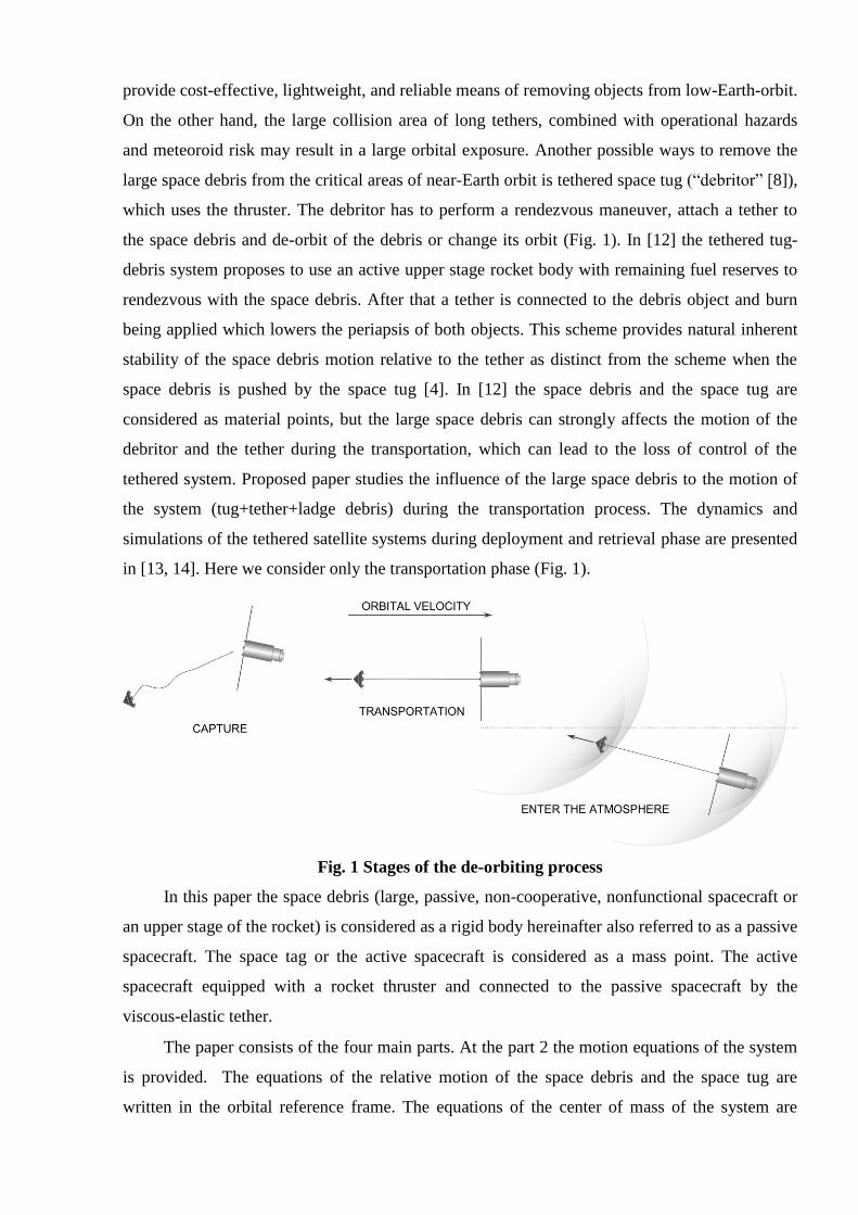
which uses the thruster. The debritor has to perform a rendezvous maneuver, attach a tether to
the space debris and de-orbit of the debris or change its orbit (Fig. 1). In [12] the tethered tug-
debris system proposes to use an active upper stage rocket body with remaining fuel reserves to
rendezvous with the space debris. After that a tether is connected to the debris object and burn
being applied which lowers the periapsis of both objects. This scheme provides natural inherent
stability of the space debris motion relative to the tether as distinct from the scheme when the
space debris is pushed by the space tug [4]. In [12] the space debris and the space tug are
considered as material points, but the large space debris can strongly affects the motion of the
debritor and the tether during the transportation, which can lead to the loss of control of the
tethered system. Proposed paper studies the influence of the large space debris to the motion of
the system (tug+tether+ladge debris) during the transportation process. The dynamics and
simulations of the tethered satellite systems during deployment and retrieval phase are presented
in [13, 14]. Here we consider only the transportation phase (Fig. 1).
Fig. 1 Stages of the de-orbiting process
In this paper the space debris (large, passive, non-cooperative, nonfunctional spacecraft or
an upper stage of the rocket) is considered as a rigid body hereinafter also referred to as a passive
spacecraft. The space tag or the active spacecraft is considered as a mass point. The active
spacecraft equipped with a rocket thruster and connected to the passive spacecraft by the
viscous-elastic tether.
The paper consists of the four main parts. At the part 2 the motion equations of the system
is provided. The equations of the relative motion of the space debris and the space tug are
written in the orbital reference frame. The equations of the center of mass of the system are

written using osculating elements of the orbit. At the part 3 several numerical examples is
considered. The influence of the parameters of the system to its motion is examined. The
correctness of the mathematical model is discussed at the part 4.
2 Motion Equation
The motion of the space debris and the space tug is considered in the rotating reference
frame o o o
Ox y z (Fig. 2). The differential equations of the centers of mass of the space debris and
the space tug are the following
1 1 1 1 1
( )io
m m a A g T D F (1)
2 2 2 2 2
iom m a A g T D (2)
where1
m , 2
m are masses of the space tug and the space debris, 1
a , 2
a are absolute accelerations
of the space tug and the space debris, ioA is a rotation matrix that transforms the coordinates
from orbital reference frame o o o
Ox y z to the Earth centered inertial frame XYZ (all vectors in
parentheses in (1) and (2) supposed to be written in the orbital frame), T is a tether force,
1 2,D D are atmospheric drag forces, F is a space tug thruster force. The absolute accelerations of
the space tug and the space debris are expressed as
2
2( ) , 1, 2
io
j o j
dj
d t
a A r ρ (3)
The positions of the space tug and the space debris relative to the center of the Earth are denoted
by the vectors 1
r and 2
r
, [ , , ] , 1, 2T
j o j j j j jx y z j r r ρ ρ (4)
where 1ρ and
2ρ are positions of the space tug and the space debris relative to the center of mass
of the system. The vector o
r describes the position of the center of mass of the system, which
performs an orbital motion. Vectoro
r has the following coordinates in the frame o o o
Ox y z
, 0, 0 1 cos
T
o
p
e
r (5)
The coordinates of the orbital velocity vector oV in the frame
o o oOx y z is
/ sin
/ (1 cos ) cos
cos( ) sin
o o o
o o
p e
p r i
r i
V

where p is a focal parameter of the orbit, e is an eccentricity, is a true anomaly, is the
standard gravitational parameter of the Earth, o
is an angular velocity of the orbital motion.
Fig. 2 The space tug and the space debris
The rotation matrix io
A is
c c c s s c s c c s s s
c c s s c c c c s s s c
s s c c
i i i
i i i
i i
io
is
A (6)
where cos , sinc s , cos , sini ic i s i , cos ( ), sin ( )
w wc w s w , i is
an orbit inclination, is an argument of perigee. The accelerations of the gravity forces are
expressed as
3, 1, 2 .
j
j
j
j r
g
r
(7)

Fig. 3 The position of the space tug relative to the orbital debris
The accelerations of the space debris and the space tug due to atmospheric drag are
1, 1, 2
2
j d j j
d j rj rj
j j
c SV j
m m
Da V
where is the atmospheric density, d j
c is a drag coefficient, j
S is an average cross-sectional area
of the spacecraft normal to its direction of travel (drag area). The drag area is directly related to
the spacecraft’s shape, dimensions and attitude motion. The term /j d j j j
BC c S m is a ballistic
coefficient. r j
V is the spacecraft’s velocity relative to the atmosphere. Due to small relative
velocity of the space tug and the space debris in comparison with orbital velocity we suppose
that the velocity vector of the space tug and the space debris with respect to the atmosphere are
equal to the velocity of the center of mass of the system relative to the atmospherero rjV V . In
the orbital reference frame vector roV
are expressed as
0
cos ,
cos( ) sin
ro o o
o
r i
r i
V V
where is an angular velocity of the Earth. We suppose that the space tug thruster force F of
constant magnitude acts along the Oy axis of the orbital frame, i. e., in the orbital frame
o o oOx y z : [0, , 0 ] , con st
TF FF . The tether force T acting on the space tug and the
passive spacecraft is defined as
1 2
0 0( ) ( )
A
l T T
dlH l l c l l d
dt l
ρ ρ ρT (8)

where0
( )l
H l l is a Heaviside step function, T
c is a tether stiffness, T
d is a tether damping, A
ρ
is a tether attachment point vector with respect to the center of mass of the space debris,
1 2 Al ρ ρ ρ is a tether length (Fig. 3).
2.1 Orbital motion
Due to acting of the atmospheric drag and the space tug thruster force the orbital
parameters change over the time. The evolution of the osculating elements of the orbit described
by the following Gauss’ variation equations [15] (an another form of Gauss’ variation equations
is presented in [16])
0
2y
pa
dp
tr
d (9)
0 0sin 1 cos
x y
er rpa a
p p
de
dt
(10)
0
0
1cos 1 sin
x y
p rpa a
d
d t r e p
(11)
0cos( )
z
d i
d
ra
pt
(12)
0 01
cos 1 sin co t sin ( )x y z
d
d t
r rpa a a e i
e p p
(13)
0sin ( )
sin z
d
d t
ra
ip
(14)
where , ,x y za a a are projections onto the orbital axes , ,
o o ox y z of the accelerations of perturbative
forces (e. g. the space tug thruster or the atmospheric drag), or is a distance from the Earth center
to the center of mass of the system. For the undisturbed Keplerian orbital elements i , , ,
e remain constant and the focal parameter p is the function of the true anomaly only.
2.2 Attitude motion of the space debris
The attitude motion of the space debris described by the Euler equations [17]
2 2 2 2 2 2
J ω ω J ω M (15)
where 2
J is an inertia tensor of the space debris
2 2 2 2
diag ( , , )A B CJ (16)

2ω is an absolute angular velocity of the space debris that is
2 2 o ω Ω ω (17)
where 2
Ω is an angular velocity of the space debris relative to the orbital frame
o o oOx y z ,
oω is
an angular velocity vector of the orbital frame relative to an inertial frame in the space debris
reference frame 2
O xyz . Vector o
ω has the following coordinates in the reference frame 2O xyz
2
sin sin ( ) cos( )
sin cos( ) sin ( )
c
( )
o s
o T
o
d d ii
d t d t
d d ii
d t d t
d d di
d t d t d t
ω A (18)
The space debris orientation relative to the reference frame o o o
Ox y z described by the
elements of the rotation matrix 2oA that transforms coordinates from the space debris principal
frame to the orbital frameo o o
Ox y z
11 12 13
2
21 22 23
31 32 33
o
a a a
a a a
a a a
A
where ( , 1, 2, 3)ij
a i j are functions of time.
The torque vector 2 T g M M M includes tether force torque
T A M ρ T , (19)
and the gravitational torque [16]
2 2
2 23
2
2 2
3z y
z x
x y
g
C B
A C
B A
r
M
where , ,x y z
are direction cosines between the axes , ,x y z of the space debris and the
vector2
r
22 2
2 32 1 2 2
2 2 2
, ,
oo o
x y z
r Ar A r A
r r r

where 2( 1, 2, 3)
o
ii A are columns of the matrix 2o
A .There is also a torque of the drag force that
we neglect. To determine space debris attitude the kinematic equations are used [17]
2
2
2
o
od
dt
AΩ A (20)
where2
Ω is an angular velocity tensor associated to the angular velocity 2
Ω
2 2
2 2 2
2 2
0
0
0
z y
z x
y x
Ω .
Equations (1), (2), (9)-(15) and (20) form a closed set of equations of the spatial motion of
the system (tug+tether+ladge debris).
3 Numerical simulation and analysis
3.1 Parameters of the system
Here the influence of the parameters of the system to its motion is studied, including the
moments of inertia of the space debris, the length and the properties of the tether, the thruster
force of the space tug and the initial conditions. Parameters of the base system are presented in
Table 1.
The axisymmetric (2 2 2,A B C ) space debris is considered on the orbit with the following
initial values of the parameters
6871 , 0 .001, 20 , 60 , 60 , 90p km e i . (21)
The space debris has initial angular velocity around its C2x axis 2x=0.05 rad/s.
Table 1 Parameters of the base system
Parameter Value Parameter Value
2A 3000 kgm2 2 2
B C 15000 kgm2
F 20 N
5 N (case 5) 2m 3000 kg
1m 500 kg T
c 60 GPa
0l
30 m
100 m (case 4) Td
0
16 Ns/m (case 3)
1dc 2
2dc 2
1S 1 m2
2S 18 m2
In the cases 1, 2, 3 and 4 the motion of the system with initially tensioned and initially
slackened tether is considered. The influence of the tether length and the tether damping to the

attitude motion of the space debris is investigated. The tethers with the length 0
30l m ,
0100l m and with the damping coefficients 10 /
Td N s m and 0
Td are considered. Initial
positions of the space tug and the space debris for the cases 1-4 are shown at Fig 4a.
In the case 5 and 6 the influence on the system under of the space tag thruster force is
examined. Initial positions of the space tug and the space debris are shown at Fig 4b for these
cases and further. In the case 7 full simulation of the descent process from the orbit (21) to the
edge of the atmosphere 100h km is presented.
a) Cases 1-4
b) Cases 5-9
Fig. 4 The initial positions and the orientations of the space tug and the space debris
3.2 Case1
Let us consider the motion of the system with initially tensioned tether. The initial angle
between the axis 2
O x and the force vector F is / 6 rad. The time history of angle and the
tether elongation 0
l l are given at Fig. 5. Fig. 5 shows that two modes of oscillation occur. A
high frequency longitudinal oscillation of the tether (Fig. 5b) and low frequency precess motion
the space debris relative to the tether due to the initial angular momentum of the space debris.

a)
b)
Fig. 5 Time history of the angle and the tether elongation for the case 1
3.3 Case 2
Next we consider the motion of the system with initially slackened tether. At 0t
0(0 ) 2 7l m l . At Fig. 6a the time history of the angle is shown. At Fig. 6b the time history
of the tether elongation is presented. The amplitude of the oscillation of the angle is higher
than in the case 1. We can expect greater tension of the tether in this case. It’s obvious that the
high oscillation of the angle during de-orbiting of the space debris should be avoided. It can
lead to the tether break or tether tangles.
a)
b)
Fig. 6 Time history of the angle and the tether elongation for the case 2
3.4 Case 3
At Fig. 7 the time history of the angle is shown for the initially slackened tether
(0
(0 ) 2 7l m l ) with damping coefficient 16 /T
d N s m . The amplitude of the oscillation of
the angle is a smaller than in the case 2, but effect of the tether damping on oscillation of the
space debris relative to the tether is insignificant.

a)
b)
Fig. 7 Time history of the angle and the tether elongation for the case 3
3.5 Case 4
Let us consider the attitude motion of the space debris with the longer tether. At Fig. 8 the
time history of the angle and the tether elongation is shown for the system with
0100l m .We note that the amplitude of the angle doesn’t differ sufficiently from the
case 1.
a)
b)
Fig. 8 Time history of the angle and the tether elongation for the case 4 (l0 = 100 m)
3.6 Case 5
Here the behavior of the system is investigated when the space tug thruster force has small
value 2F N and the initial value of angle is equal to 0. Fig. 9a shows the time history of
angle . Angle is increased due to the orbital motion of the space debris and its initial
angular momentum.

3.7 Case 6
The Fig. 9b shows how the angle changes when the space tug force is ten times greater
than in the previous case ( 20F N ). We note the ten times smaller amplitude oscillation of the
angle compared to case 5. The thruster force must be sufficed to retain small angle .
a) 2F N
b) 20F N
Fig. 9 Time history of the angle for the cases 5 and 6
3.8 Case 7
At last, let us consider the descent process of the space debris from the near-circular orbit
with 500h km to the edge of the Earth’s atmosphere 100h km . The results of the simulation
are presented at Fig. 10. Fig. 10a shows the time history of the angle and the evolution of the
orbit height of the system. We note that the height of the space debris falls below 100 km after
the 7 turns around the Earth. The life time of the space debris on the initial orbit at least six years
[18]. The space tug de-orbit the space debris in 11-12 hours. Note that after 11 hours the tether
slacked and two spacecraft approach each other. The space tug can come into collision with the
connected space debris. This collision can increase uncertainty of the initial conditions of the
space debris at the beginning of the atmospheric stage of the descent process.
a)
b)
Fig. 10 Time history of the angle and the tether elongation for the case 8

Let us provide detail analysis of the motion of the system at the low altitude (100-120 km)
where the atmospheric drag is essential. The atmospheric drag is the main non-gravitational
force that acts on a satellite in LEO. Drag is part of the total aerodynamic force that acts on a
body moving through an atmosphere. It acts in the direction opposite of the velocity. The large
space debris with large cross section area can slow down by the atmospheric drag much stronger
then the space tug. In this case tether slacks and the space debris can collide with the space tug.
To avoid tether slackness the space tug thrust force F should be such that (Fig. 11a)
1 2
1 2
0D F D
m m
(22)
or
*1
2 1 1 1 1
2 2 1
1 1( ) ( )
mF F F m q h m q h B C
m B C B C
(23)
where 2
0 .5 ( )o
q h V is a dynamic pressure1
BC is a ballistic coefficient of the space tug, 2
B C is
a ballistic coefficient of the space debris. The minimal space tug force that ensure the tension of
the tether is
m in 1
2 1
1 1F q h m
B C B C
(24)
At Fig.11b the minimal force of the space tug as a function of height is shown for two
types of the space debris. The atmosphere density approximated by the function
/ 7000 3
0 0e , .( ) 1 1 /
hkg mh
a)
b)
Fig. 11 Minimal space tug force for two types of the space debris
(the ballistic coefficient of the space tug BC1=250 kg/m2)
For the particular system parameters the minimal height of the safe transportation exists
below which the tether can slack. This height depends on the maximum thruster force of the
space tug and on the ballistic coefficients of the space tug and the space debris. Below this height
the space tug can come into collision with the connected space debris. The collision can
increases uncertainty of the initial conditions of the space debris at the beginning of the

atmospheric stage of descent process. The space tug has to perform reorient maneuver before re-
entering Earth's atmosphere to prevent the collision with the space debris.
4 Model correctness
The motion of the space debris and the space tug is considered relative to the center of
mass of the system. The position of the space tug and the space debris relative to the center of
mass of the system described by the vectors 1ρ and
2ρ respectively. The vectors
1ρ and
2ρ are
obtained from the independent differential equations (1) and (2). For the center of mass vector of
the system Cρ takes place the following expression
1 2 1 1 2 2
( ) 0C
m m m m ρ ρ ρ
(25)
For the correct mathematical model Cρ should be equal to zero vector or close to the zero vector
due to errors the numerical integration process. During numerical simulation the error of the
position of the center mass is tested. For all considered cases norm of the vector c is less than
0.001 meters.
Conclusion
The influence of the parameters of the system to its motion, including the moments of
inertia of the space debris, the length and the properties of the tether, the thruster force of the
space tug and the initial conditions of the motion is studied. The safe transportation process is
possible when the space tug force vector coincides with the direction of the tether and the tether
is always tensioned. Tether damping device slightly reduces the amplitude oscillations of the
space debris. The space tug has to keep sufficient level of the thruster force to eliminate the high
amplitude oscillations of the space debris relative to the tether. There is the minimal height of the
safe transportation below which the space tug can come into collision with the connected space
debris.
Acknowledgements
This research was supported by Russian Foundation for Basic Research (12-01-00317-a).
References
[1] V. Braun, A. Lüpken, S. Flegel, J. Gelhaus, M. Möckel, C. Kebschull, C. Wiedemann, P.
Vörsmann, Active Debris Removal of Multiple Priority Targets, Advances in Space Research,
Available online 13 December 2012, ISSN 0273-1177, 10.1016/j.asr.2012.12.003.
[2] B. Bastida, H. Krag, Strategies for Active Removal in LEO. 5th European Conference on
Space Debris, Germany, 2009.

[3] J. C. Liou, N. L. Johnson, A sensitivity study of the effectiveness of active debris removal
in LEO. ActaAstronautica, Volume64, Issue 2-3 (2008), 236–243.
[4] C. Kaiser, E. Bellido, P. Hofmann, Space debris mitigation using on-orbit servicing
solutions, IAC-12.A6.5.29, 63rd International Astronautical Congress, 1-5 October 2012,
Naples, Italy.
[5] L. T. DeLuca, Active space debris removal by hybrid engine module, IAC-12-A6.5.8, 63rd
International Astronautical Congress, 1-5 October 2012, Naples, Italy.
[6] Bischof, B., Kerstein, L., Starke, J., Guenther, H., Foth, W., 2004. ROGER- Robotic
geostationary orbit restorer. Science and Technology Series 109, 183–193.
[7] P. Williams, A Review of Space Tether Technology, Recent Patents on Space
Technology. 2 (2012) 22–36.
[8] C. Cougnet, D. Alary, B. Gerber, J. Utzmann, A. Wagner, The debritor: an “Off the shelf”
based multimission vehicle, IAC-12-A6.7.7, 63rd International Astronautical Congress, 1-5
October 2012, Naples, Italy.
[9] R.P. Hoyt, I.M. Barnes, N.R. Voronka, J.T. Slostad, The Terminator Tape: A cost-effective
de-orbit module for end-of-life disposal of LEO satellites, in: AIAA Space 2009 Conference,
2009: p. 6733.
[10] Nishida, S.-I., Kawamoto, S., Okawa, Y., Terui, F., Kitamura, S., 2009. Space debris
removal system using a small satellite. Acta Astronautica 65, 95–102.
[11] Yamaigiwa, Y., Hiragi, E., Kishimoto, T. Dynamic behavior of electrodynamic tether
deorbit system on elliptical orbit and its control by Lorentz force. Aerospace Science and
Technology 9 (2005), 366–373.
[12] Lee E. Z. Jasper, Seubert, C. R., Schaub, H., Trushlyakov, V., and Yutkin, V., “Tethered
Tug For Large Low Earth Orbit Debris Removal,” AAS/AIAA Astrodynamics Specialists
Conference, Charleston, South Carolina, 2012.
[13] K. K. Mankala, S. K. Agrawal Dynamic Modeling and Simulation of Impact in Tether
Net/Gripper Systems,Multibody System Dynamics. 11 (2004), 235–250.
[14] Nishida, S.-I., Kawamoto, S., 2011. Strategy for capturing of a tumbling space debris. Acta
Astronautica 68, 113–120.
[15] Elyasberg, P. E. Vvedenie v teoriyu poleta iskusstvennyh sputnikov Zemli [in Russian].
Moskva : Izd-vo "Nauka". 1965. p. 303.
[16] H. Schaub, J. L. Junkins Analytical mechanics of aerospace systems, AIAA, 2002. p. 417.
[17] J. Wittenburg, Dynamics of Multibody Systems, Springer-Verlag, 2008.
[18] NASA Debris Assessment Software, Version 2.0.2 http://orbitaldebris.jsc.nasa.gov.
Related Documents