IEEE TRANSACTIONS ON INDUSTRY APPLICATIONS, VOL. IA-21, NO. 4, JULY/AUGUST 1985 Dynamically Optimal Switching Patterns for PWM Inverter Drives (for Minimization of the Torque and Speed Ripples) FRANZ C. ZACH, MEMBER, IEEE, ROBERTO MARTINEZ, SIEGFRIED KEPLINGER, AND ALBERT SEISER Abstract-Several optimization criteria exist for pulsewidth modula- tion (PWM) inverter control as applied to ac motor drives. Drive dynamics, i.e., torque and speed ripples, are analyzed and optimized. As a representative example, the PWM inverter control is assumed to have three and five degrees of freedom. These degrees of freedom are realized by so-called switching angles which determine the inverter output voltage waveshape. This voltage is applied to an induction motor. Analysis is executed for a steady-state approximation (using Fourier analysis) as well as for the rigorous fifth-order dynamic equations. The results are compared. The optimal solution for the switching angles as a function of the voltage fundamental is shown. The location of the optima is compared with the efficiency optimal control presented in an earlier paper. A means is provided to compare results for different optimization criteria in order to reach an overall optimum as the best compromise between the results gained from the different optimization methods. I. INTRODUCTION SEVERAL optimization criteria can be identified for power electronic systems. If one considers, e.g., pulsewidth modulation (PWM) inverters as used for ac motor drives, especially the following criteria should be taken into account: optimal efficiency, optimal drive dynamics (i.e., minimization of torque, speed, and position ripples), minimization of current peaks (especially in the switching devices), minimiza- tion of voltage peaks across the devices and electromagnetic influence minimization. (Other more commercially oriented criteria are considered beyond the scope of this paper.) This paper treats the torque and especially the speed ripple minimization by optimizing the PWM patterns. For this purpose, a microprocessor-controlled transistor inverter is assumed (Fig. 1). Typical output voltage wave patterns are shown in Fig. 2. There, NM I denotes negative values of URO in 7r/2, PMI stands for positive values there. The aim of this paper is to find switching angles oil, a2, a3 (see Fig. 2) generated by microprocessor control which lead to minimal deviations of the instantaneous torque and speed values from the average torque and speed. Also, the case of five switching angles will be treated, but the same approach also is valid for any number of such angles. In this paper, the speed shall be considered primarily. So far in the literature, e.g., in [3], the Paper IPCSD 84-48, approved by the Industrial Drives Committee of the IEEE Industry Applications Society for presentation at the 1984 Industry Applications Society Annual Meeting, Chicago, IL, April 3-6, 1984. Manuscript released for publication November 8, 1984. This work was supported by the Austrian Fonds zur Foerderung der wissenschaftlichen Forschung. The authors are with the Department of Power Electronics at the Institute of Electronics, University of Technology, 359.5, Gusshaustrasse 27, A-1040 Vienna, Austria. I For a detailed explanation of NM and PM, see the Appendix. efficiency has been optimized and in [4] the torque behavior has been analyzed for current source inverters. Optimization of the dynamic behavior (and, generally, treatment of the voltage source inverter for this purpose) seems to be new here. II. INVERTER VOLTAGES AND DRIVE DYNAMICS Inverter and Motor Voltages Fig. 1 shows the structure of the drive with the transistor inverter, alternating current machine, and the microprocessor controller. The latter not only provides closed loop control functions but also generates the PWM pulses [14]. The PWM pulses are shown in Fig. 2 for a special example. Due to the symmetries only uneven order harmonics may exist. All harmonics with orders of k = 3m; m = 1, 2, 3, are of no interest due to the cancellation effect in three-phase applications, as considered here. The harmonics can be expressed as follows [10]: 4Ud ak=- (1-2 cos ka, k-r +2 cos kcI2-2 cos kC13 ± ± 2 cos kaj) e.g., for URO, or, normalized, Uk=aklr/(4Ud). (1) (2) The ak are the amplitudes (equivalent to the Fourier coeffi- cients) of the harmonics (including the fundamental) of URM. The minus sign for the last term is valid if the number (n) of switching actions per quarter period is uneven, plus is valid for n even. The normalized stator voltages (phase voltages with respect to the load center) in general are expressed by Ua = Z Uk sin (koIt +k) k Ub = U Uk sin (kcoIt + k-2k7r/3) k Uc = I Uk sin (kwI,t + tk-4k7r/3) k (3) where a, b, c denote the three phases for normalized values in place of R, S, T. Considering positive and negative se- quences, we can write for the stator voltages [11] (4) US = uSkfejkfoit + uskb*eikbwlt kf kb 0093-9994/85/0700-0975$01 .00 © 1985 IEEE 975

Welcome message from author
This document is posted to help you gain knowledge. Please leave a comment to let me know what you think about it! Share it to your friends and learn new things together.
Transcript
IEEE TRANSACTIONS ON INDUSTRY APPLICATIONS, VOL. IA-21, NO. 4, JULY/AUGUST 1985
Dynamically Optimal Switching Patterns for PWMInverter Drives (for Minimization of the Torque and
Speed Ripples)FRANZ C. ZACH, MEMBER, IEEE, ROBERTO MARTINEZ, SIEGFRIED KEPLINGER, AND ALBERT SEISER
Abstract-Several optimization criteria exist for pulsewidth modula-tion (PWM) inverter control as applied to ac motor drives. Drivedynamics, i.e., torque and speed ripples, are analyzed and optimized. Asa representative example, the PWM inverter control is assumed to havethree and five degrees of freedom. These degrees of freedom are realizedby so-called switching angles which determine the inverter output voltagewaveshape. This voltage is applied to an induction motor. Analysis isexecuted for a steady-state approximation (using Fourier analysis) as wellas for the rigorous fifth-order dynamic equations. The results arecompared. The optimal solution for the switching angles as a function ofthe voltage fundamental is shown. The location of the optima iscompared with the efficiency optimal control presented in an earlierpaper. A means is provided to compare results for different optimizationcriteria in order to reach an overall optimum as the best compromisebetween the results gained from the different optimization methods.
I. INTRODUCTIONSEVERAL optimization criteria can be identified for power
electronic systems. If one considers, e.g., pulsewidthmodulation (PWM) inverters as used for ac motor drives,especially the following criteria should be taken into account:optimal efficiency, optimal drive dynamics (i.e., minimizationof torque, speed, and position ripples), minimization ofcurrent peaks (especially in the switching devices), minimiza-tion of voltage peaks across the devices and electromagneticinfluence minimization. (Other more commercially orientedcriteria are considered beyond the scope of this paper.) Thispaper treats the torque and especially the speed rippleminimization by optimizing the PWM patterns. For thispurpose, a microprocessor-controlled transistor inverter isassumed (Fig. 1). Typical output voltage wave patterns areshown in Fig. 2. There, NM I denotes negative values of URO in7r/2, PMI stands for positive values there. The aim of thispaper is to find switching angles oil, a2, a3 (see Fig. 2)generated by microprocessor control which lead to minimaldeviations of the instantaneous torque and speed values fromthe average torque and speed. Also, the case of five switchingangles will be treated, but the same approach also is valid forany number of such angles. In this paper, the speed shall beconsidered primarily. So far in the literature, e.g., in [3], the
Paper IPCSD 84-48, approved by the Industrial Drives Committee of theIEEE Industry Applications Society for presentation at the 1984 IndustryApplications Society Annual Meeting, Chicago, IL, April 3-6, 1984.Manuscript released for publication November 8, 1984. This work wassupported by the Austrian Fonds zur Foerderung der wissenschaftlichenForschung.The authors are with the Department of Power Electronics at the Institute of
Electronics, University of Technology, 359.5, Gusshaustrasse 27, A-1040Vienna, Austria.
I For a detailed explanation of NM and PM, see the Appendix.
efficiency has been optimized and in [4] the torque behavior hasbeen analyzed for current source inverters. Optimization ofthe dynamic behavior (and, generally, treatment of the voltagesource inverter for this purpose) seems to be new here.
II. INVERTER VOLTAGES AND DRIVE DYNAMICSInverter and Motor Voltages
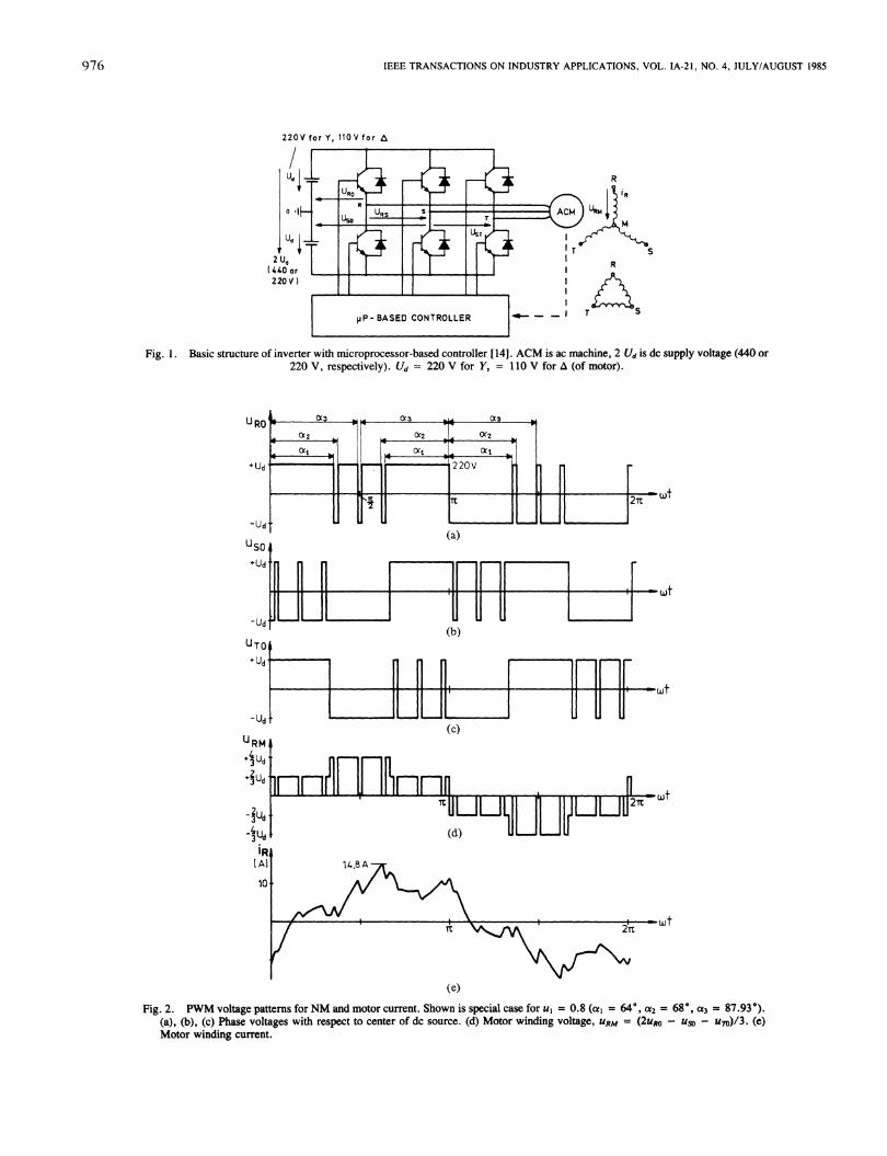
Fig. 1 shows the structure of the drive with the transistorinverter, alternating current machine, and the microprocessorcontroller. The latter not only provides closed loop controlfunctions but also generates the PWM pulses [14]. The PWMpulses are shown in Fig. 2 for a special example. Due to thesymmetries only uneven order harmonics may exist.
All harmonics with orders of k = 3m; m = 1, 2, 3, areof no interest due to the cancellation effect in three-phaseapplications, as considered here. The harmonics can beexpressed as follows [10]:
4Udak=- (1-2 cos ka,
k-r
+2 cos kcI2-2 cos kC13 ±±2 cos kaj)e.g., for URO, or, normalized,
Uk=aklr/(4Ud).
(1)
(2)The ak are the amplitudes (equivalent to the Fourier coeffi-cients) of the harmonics (including the fundamental) of URM.The minus sign for the last term is valid if the number (n) ofswitching actions per quarter period is uneven, plus is valid forn even.The normalized stator voltages (phase voltages with respect
to the load center) in general are expressed by
Ua =Z Uk sin (koIt+k)k
Ub = UUk sin (kcoIt + k-2k7r/3)k
Uc=I Uk sin (kwI,t+ tk-4k7r/3)k
(3)
where a, b, c denote the three phases for normalized values inplace of R, S, T. Considering positive and negative se-quences, we can write for the stator voltages [11]
(4)US= uSkfejkfoit + uskb*eikbwltkf kb
0093-9994/85/0700-0975$01 .00 © 1985 IEEE
975
IEEE TRANSACTIONS ON INDUSTRY APPLICATIONS, VOL. IA-21, NO. 4, JULY/AUGUST 1985
220V for Y, 110 V for A
2 Ud( 4I0 or220V)
Fig. 1. Basic structure of inverter with microprocessor-based controller [14]. ACM is ac machine, 2 Ud is dc supply voltage (440 or220 V, respectively). Ud = 220 V for Y, = 110 V for A (of motor).
220V h
(a)
F2Tt
(b)
(c)
(e)
Fig. 2. PWM voltage patterns for NM and motor current. Shown is special case for ul = 0.8 (a1 = 640, a2 = 68°, a3 = 87.93°).(a), (b), (c) Phase voltages with respect to center of dc source. (d) Motor winding voltage, URM = (2URo - Uso - un)/3. (e)Motor winding current.
L (X2aI ft 1F b
CYf D.*WI (Xi
II-
[ID V+Ud'
-Ud
UTO+ Ud
-Ud
10o
0.
l'- OctT
976
ZACH et al.: DYNAMICALLY OPTIMAL SWITCHING PATTERNS FOR PWM INVERTER
where kf = (6m - 5), m = 1, 2, 3, , is the order ofharmonics which induce rotating magnetic fields in the samedirection as does the fundamental, and kb = (6m - 1), m =1, 2, 3, , is the order of harmonics inducing backwardrotating field; index s for stator.
Exact Calculation of DynamicsThe exact motor equations are of fifth order. They can be
expressed by (e.g., [1], [2], [6], [8], [9], [11])
di5a djraRlisa+LI d +LMdi= Usa
dt dt
RIiss + LI dis+dLMdmdir,dt dt"s
R2ira+ L2( d + W,) +LM (di f =0dt /dt /
R2irO + L2( Wi&, + LM (d wis =
damJ-bm= T- TLdtdtSm
J t = (3/2)pLM(ira is6 -ir, isj)-TL
Wr=P C)m(ech) =P ' m(ech)
LI=LM+LIS, L2=LM+L2S
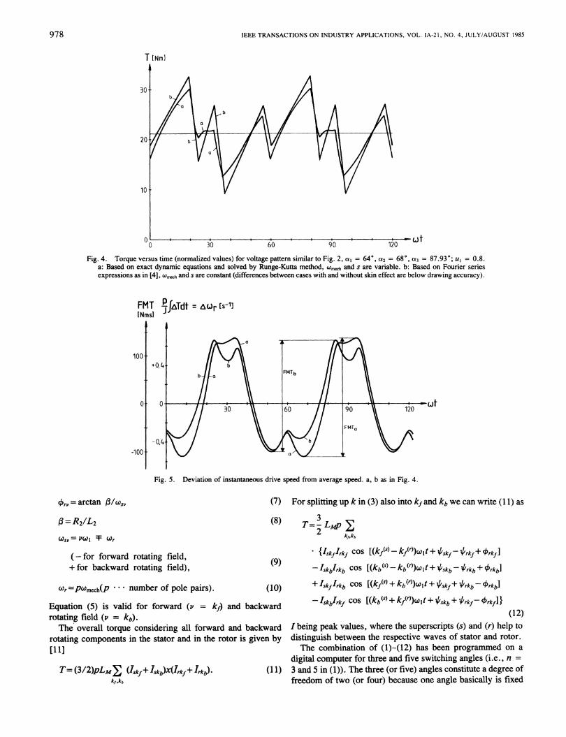
where a, j3 indicate the rectangular coordinate system fixed tothe stator, p is the pole pair number, index r is for rotor, L forload, m or mech for mechanical angle and speed. Thiscomplete set of equations has been programmed on a digitalcomputer. (Consideration of frequency-dependent parameterswill be the topic of a future paper. Here comparison has beenmade with the following Fourier series approach without skineffect.) An improved Runge-Kutta method [15] was applied,where Wmech and s are considered as variables. The statorcurrent obtained is shown in Fig. 2(e); also, torque and speedwere calculated dependent on the voltage patterns given byFig. 2, as shown in Figs. 4 and 5. The variation of theswitching angles ai (Fig. 2) yields different torque and speedbehavior. How this variation of the ai is used to optimize thear-control is shown later.
Fourier Series Approach for Dynamics CalculationThe rigorous calculation described before in the average
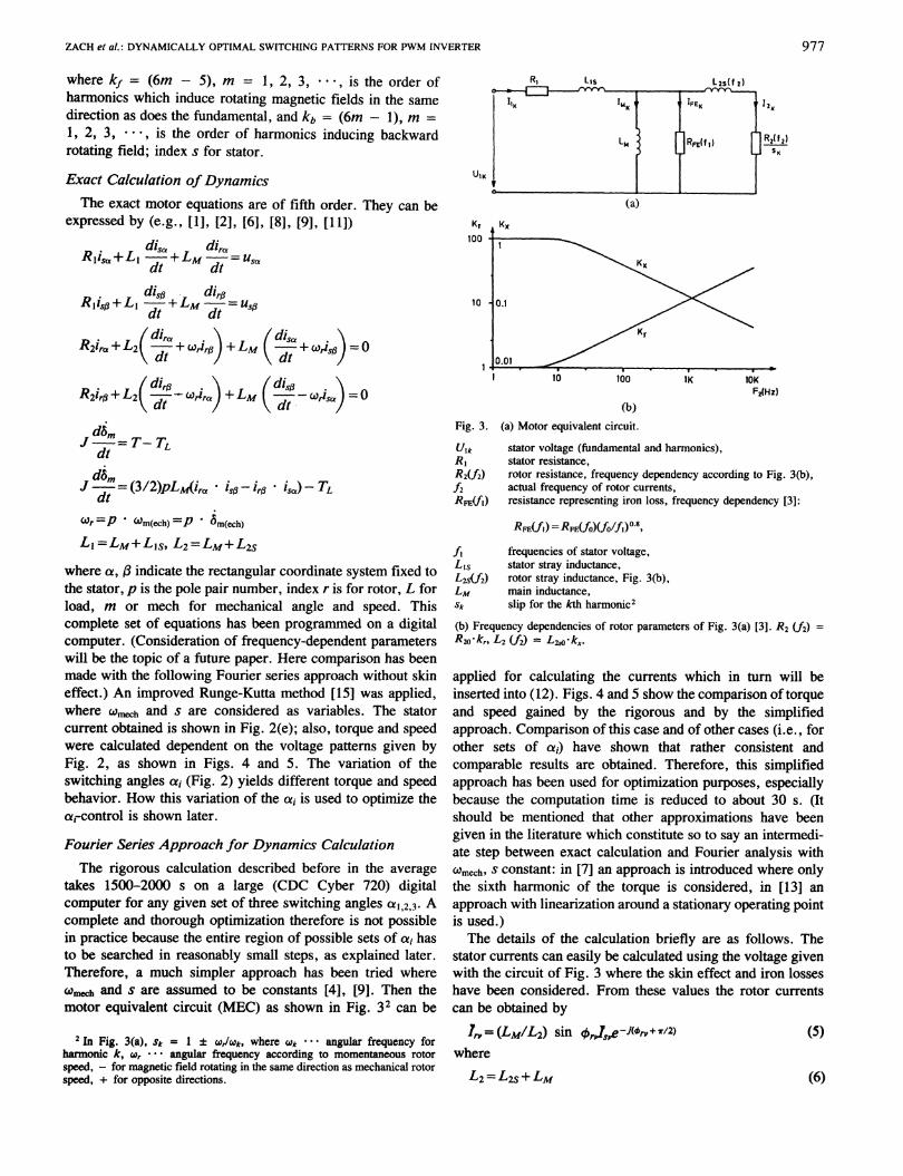
takes 1500-2000 s on a large (CDC Cyber 720) digitalcomputer for any given set of three switching angles a1,2,3. Acomplete and thorough optimization therefore is not possiblein practice because the entire region of possible sets of ai hasto be searched in reasonably small steps, as explained later.Therefore, a much simpler approach has been tried wherewmech and s are assumed to be constants [4], [9]. Then themotor equivalent circuit (MEC) as shown in Fig. 32 can be
2 In Fig. 3(a), Sk = 1 ± W/Wk, where Wk ... angular frequency forharmonic k, wr ... angular frequency according to momentaneous rotorspeed, - for magnetic field rotating in the same direction as mechanical rotorspeed, + for opposite directions.
Kr100
10
Fig. 3.
UlkRIR2(f2)f2RFE(fl)
IRI Lis Lzs(f 2)is
IIK im IFEK IF 12K
i ~~~~ ~ ~~~~LmRFCR(f ) RZ(f,2)SK
(a)
IOKF2(Hz)
(b)(a) Motor equivalent circuit.
stator voltage (fundamental and harmonics),stator resistance,rotor resistance, frequency dependency according to Fig. 3(b),actual frequency of rotor currents,resistance representing iron loss, frequency dependency [3]:
RFE(_fl)= RFE(_f)( fO1fi) 0 8,
f, frequencies of stator voltage,Lis stator stray inductance,L2Sf2) rotor stray inductance, Fig. 3(b),LM main inductance,Sk slip for the kth harmonic2
(b) Frequency dependencies of rotor parameters of Fig. 3(a) [3]. R2 (A) =R2k,, L2 (A2) = L2S0-kX
applied for calculating the currents which in turn will beinserted into (12). Figs. 4 and 5 show the comparison of torqueand speed gained by the rigorous and by the simplifiedapproach. Comparison of this case and of other cases (i.e., forother sets of a1) have shown that rather consistent andcomparable results are obtained. Therefore, this simplifiedapproach has been used for optimization purposes, especiallybecause the computation time is reduced to about 30 s. (Itshould be mentioned that other approximations have beengiven in the literature which constitute so to say an intermedi-ate step between exact calculation and Fourier analysis witht0mech, s constant: in [7] an approach is introduced where onlythe sixth harmonic of the torque is considered, in [13] anapproach with linearization around a stationary operating pointis used.)The details of the calculation briefly are as follows. The
stator currents can easily be calculated using the voltage givenwith the circuit of Fig. 3 where the skin effect and iron losseshave been considered. From these values the rotor currentscan be obtained by
7, = (Lm/L2) sin 4',.J,,e-i(Or,+T/2) (5)where
977
UIK
L2 =L2S+Lm (6)
IEEE TRANSACTIONS ON INDUSTRY APPLICATIONS, VOL. IA-21, NO. 4, JULY/AUGUST 1985
T [NmI
ct
Fig. 4. Torque versus time (normalized values) for voltage pattern similar to Fig. 2, a, = 64°, 0a2 = 680, a3 = 87.93°; ul = 0.8.a: Based on exact dynamic equations and solved by Runge-Kutta method, Wech and s are variable. b: Based on Fourier seriesexpressions as in [4], '0meh and s are constant (differences between cases with and without skin effect are below drawing accuracy).
FMT .faTdt = wj, (s-I]I Nmsl
100i
0
-loot
Fig. 5. Deviation of instantaneous drive speed from average speed. a, b as in Fig. 4.
krp= arctan f3/W.,.
fl= R2/L2Ws,= P( I T C°r
(-ffr forwqrdl rntqtin fit-Id
(7) For splitting up k in (3) also into kf and kb we can write (11) as
(8)
k-V IvIWl IVLailr I vV.;IU5'sv (9)+for backward rotating field),
Wr=PWmech(P number of pole pairs). (10)
Equation (5) is valid for forward (v = kf) and backwardrotating field (v = kb)The overall torque considering all forward and backward
rotating components in the stator and in the rotor is given by[1 1]
T= (3/2)pLMY (Iskf+ Iskb)X(lrkf+ Irkb).kf,kb
T= -Lmp YT2~LMP kf,kb
{IskfIrkf cos Rkf(s)-kf(r))wlt + Vskf-{ rkf+ 'rkfI
-Iskb'rkb COS [(kb(s) - kb (r))cjt + /skb - 'rkb + frkb]
+ Iskf'rkb COS [(kf( ) + kb (r))W t + /skf+ 1//rkb- 'krkb]
-IskbIrkf COS [(kb( ) + kf(r))(W.1lt + 1/1skb + lkrkf-")rkf I}(12)
I being peak values, where the superscripts (s) and (r) help to
distinguish between the respective waves of stator and rotor.The combination of (I)-(12) has been programmed on a
digital computer for three and five switching angles (i.e., n =
3 and 5 in (1)). The three (or five) angles constitute a degree offreedom of two (or four) because one angle basically is fixed
978
ZACH et al.: DYNAMICALLY OPTIMAL SWITCHING PATTERNS FOR PWM INVERTER
once the voltage fundamental a, has been set (a, is also givenby (1)).
These remaining two (or four) angles can be varied on thecomputer in order to optimize the system performance. Eachset of angles results in a torque and speed behavior as shownfor a special case in Figs. 4 and 5.
It should be mentioned that a first approach in the literaturehad been to eliminate lower order voltage harmonics com-pletely [1], [10], [12]. (An improved solution for thisapproach is given in [3].) Three or five switching angles(generally an odd number of switching angles) are of specialinterest because then in the case of selected harmonicelimination (SHE) the sixth or the sixth and the twelfth (or alsohigher order) harmonic torques can be eliminated completely.This does not say that in our opinion it is very advantageous toeliminate certain harmonics completely because then theremaining harmonics are highly increased. The new approachas described here gives a thorough and exact optimization.This means that all harmonics are taken into consideration andoverall torque and speed ripples are treated and improved.
HII. OPTIMIZATION PROCEDUREThree Switching Angles-General IdeasAs indicated previously, for the purpose of calculating the
drive dynamics, the voltage patterns according to Fig. 2 in afirst approach are applied to the exact induction machineequations using an improved Runge-Kutta method, leading toFigs. 4 and 5. For Ar, the deviation ATof the torque Tfromits mean (average) value Tav is taken and integrated, since
=-J | T dt (13)
where Wr/P is the rotor speed ( = Cmh) and J is the moment ofinertia.A mean value Tav in T with Ta, * 0 would lead to a linearly
rising Wr which is of no interest here. As optimizationcriterion, the figure of merit for torque (FMT, proportional toAor.,, being the variation of the instantaneous speed Wrbetween its lowest and its highest value) is taken (Fig. 5):
FMT= JACrmax/P= maximum peak-to-peak value of
AT dt .(14)
For an optimization of the switching angles ai a large numberof cases with various combinations of such switching angleshas to be taken. (The great number of various cases necessaryis based on the fact that a complete search has to be performed.The variation can be performed basically by steepest descentmethods applying initial guesses. The danger with thisapproach is, however, that in many cases only local optima arefound. To be safe, a multitude of initial guesses has to be used.This has been tried here also. However, to be completelycertain, it has turned out to be better and in the long run evenless time consuming to search the entire region of possible
I
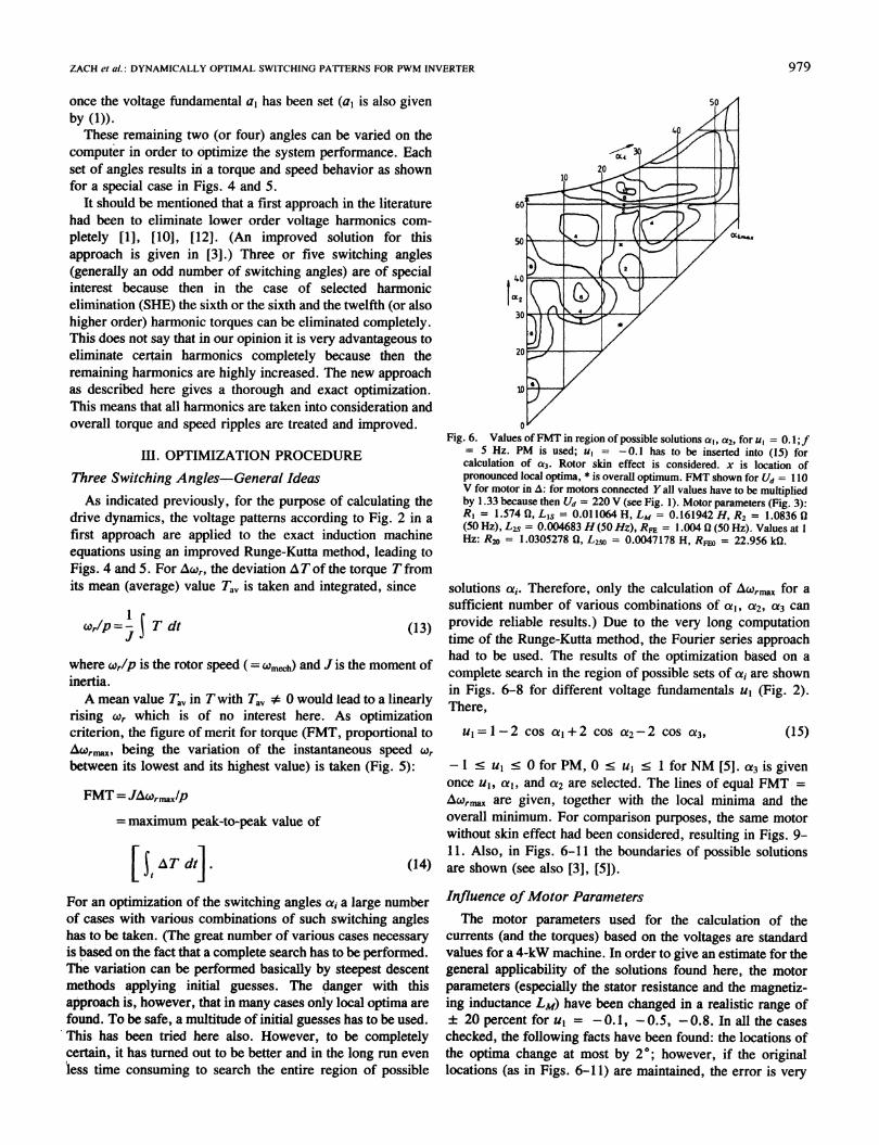
Fig. 6. Values ofFMT in region of possible solutions at, a2, for ul = 0. 1;f= 5 Hz. PM is used; ul = -0.1 has to be inserted into (15) forcalculation of a3. Rotor skin effect is considered. x is location ofpronounced local optima, * is overall optimum. FMT shown for Ud = 110V for motor in A: for motors connected Y all values have to be multipliedby 1.33 because then Ud = 220 V (see Fig. 1). Motor parameters (Fig. 3):RI = 1.574 1, Li5 = 0.01 1064 H, LM = 0.161942 H, R2 = 1.0836 n(50 Hz), Ls = 0.004683 H (50 Hz), RFE = 1.004 0 (50 Hz). Values at 1Hz: R20 = 1.0305278 0, L2so 0.0047178 H, RFE0 = 22.956 kS2.
solutions Cia. Therefore, only the calculation of Awrma for asufficient number of various combinations of al, ai2, ai3 canprovide reliable results.) Due to the very long computationtime of the Runge-Kutta method, the Fourier series approachhad to be used. The results of the optimization based on acomplete search in the region of possible sets of a, are shownin Figs. 6-8 for different voltage fundamentals ul (Fig. 2).There,
(15)u=l--2 cos ol+2 cos oz2-2 cos a3,
-Is ul < OforPM, 0<uc l < 1 forNM [5]. a3is givenonce ul, a,, and a2 are selected. The lines of equal FMT =AWripaxa are given, together with the local minima and theoverall minimum. For comparison purposes, the same motorwithout skin effect had been considered, resulting in Figs. 9-11. Also, in Figs. 6-11 the boundaries of possible solutionsare shown (see also [3], [51).
Influence of Motor ParametersThe motor parameters used for the calculation of the
currents (and the torques) based on the voltages are standardvalues for a 4-kW machine. In order to give an estimate for thegeneral applicability of the solutions found here, the motorparameters (especially the stator resistance and the magnetiz-ing inductance LM) have been changed in a realistic range of± 20 percent foru1 = -0.1, 0.5, -0.8. In all the caseschecked, the following facts have been found: the locations ofthe optima change at most by 20; however, if the originallocations (as in Figs. 6-11) are maintained, the error is very
979
IEEE TRANSACTIONS ON INDUSTRY APPLICATIONS, VOL. IA-21, NO. 4, JULY/AUGUST 1985
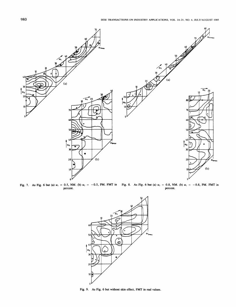
(a)(a)
Fig. 7. As Fig. 6 but (a) u1 = 0.5, NM. (b) u1 = -0.5, PM. FMT inpercent.
Fig. 8. As Fig. 6 but (a) u, = 0.8, NM. (b) u1 = -0.8, PM. FMT inpercent.
S
KZ4 zAZI2
20
10
0'
0L
U
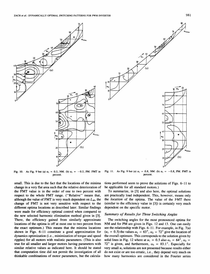
Fig. 9. As Fig. 6 but without skin effect, FMT in real values.
980
Oct
4%.----\
x 14
("I.)
ZACH et al.: DYNAMICALLY OPTIMAL SWITCHING PATTERNS FOR PWM INVERTER
Fig. 10. As Fig. 9 but (a) u1 = 0.5, NM. (b) ul = -0.5, PM. FMT in Fig. 11. As Fig. 9 but (a) uI = 0.8, NM. (b) uI = -0.8, PM. FMT inpercent. percent.
small. This is due to the fact that the locations of the minimachange in a very flat area such that the relative deterioration ofthe FMT value is in the order of one to two percent withrespect to the whole FMT range. ("Relative" means that,although the value of FMT is very much dependent on LM, thechange of FMT is not very sensitive with respect to thedifferent optima locations as described later. Similar findingswere made for efficiency optimal control when compared tothe new selected harmonic elimination method given in [3].There, the efficiency gained from similarly approximatelocations of the optima is off at most one to two percent fromthe exact optimum.) This means that the minima locationsshown in Figs. 6-11 constitute a good approximation fordynamics optimization (i.e., minimization of torque and speedripples) for all motors with realistic parameters. (This is alsotrue for all smaller and larger motors having parameters withsimilar relative values as indicated here. It should be statedthat computation time did not permit the investigation of allthinkable combinations of motor parameters, but the calcula-
tions performed seem to prove the solutions of Figs. 6-11 tobe applicable for all standard motors.)To summarize, in [3] and also here, the optimal solutions
are practically load indbpendent. This, however, means onlythe location of the optima. The value of the FMT there(similar to the efficiency value in [3]) is certainly very muchdependent on the specific motor.
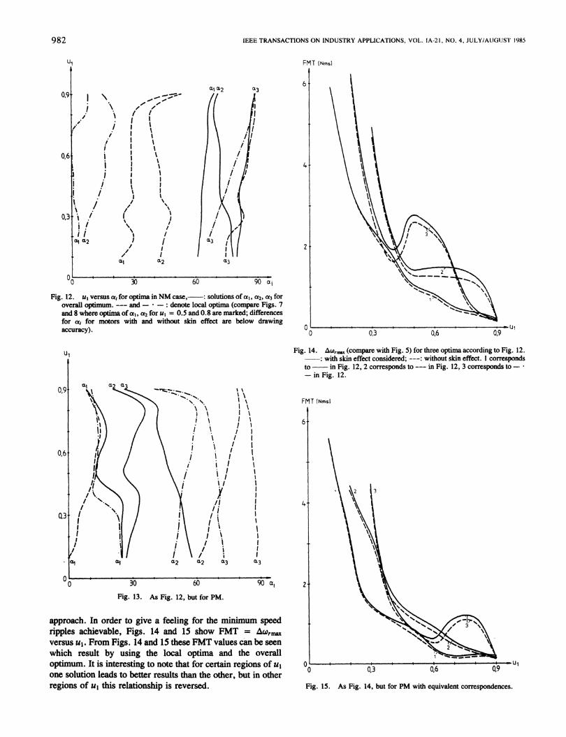
Summary of Results for Three Switching AnglesThe switching angles for the most pronounced optima for
NM and for PM are given in Figs. 12 and 13. One can easilysee the relationship with Figs. 6-1 1. For example, in Fig. 7(a)(ul = 0.5) the values a, = 63°, a2 = 72° give the location ofthe overall optimum. This corresponds to the solution given bysolid lines in Fig. 12 where at ul = 0.5 also a, = 64°, a2 =720 is given, and furthermore, a3 = 83.10. Especially forvery small ul solutions are not presented because results eitherdo not exist or are too erratic, i.e., they depend very much onhow many harmonics are considered in the Fourier series
981
IEEE TRANSACTIONS ON INDUSTRY APPLICATIONS, VOL. IA-21, NO. 4, JULY/AUGUST 1985
U'
0,9
0,6
0,3
I
/./
//i!
i/I
i .}I!
i !i I
al4 a2
/
/
I
- -I
t lI
I II \t
II I
I
I II ;2
/L
30 60 90 ai
Fig. 12. us versus ac for optima inNM case, : solutions ofa1, a2, t3 foroverall optimum. --- and - -: denote local optima (compare Figs. 7and 8 where optima of a1, a2 for ul = 0.5 and 0.8 are marked; differencesfor at, for motors with and without skin effect are below drawingaccuracy).
Fig. 14. Awr (compare with Fig. 5) for three optima according to Fig. 12.: with skin effect considered; ---: without skin effect. 1 corresponds
to in Fig. 12, 2 corresponds to --- in Fig. 12, 3 corresponds to -- in Fig. 12.
FMT INmsi
6
4'2
a, 2
Fig. 13. As Fig. 12, but for PM.
approach. In order to give a feeling for the minimum speedripples achievable, Figs. 14 and 15 show FMT = Ar)versus ul. From Figs. 14 and 15 these FMT values can be seen
which result by using the local optima and the overalloptimum. It is interesting to note that for certain regions of usone solution leads to better results than the other, but in otherregions of ul this relationship is reversed.
O .U1 .|__. _ I _ - I Ul0 0,3 0,6 0,9
Fig. 15. As Fig. 14, but for PM with equivalent correspondences.
FMT INmsI
6
2
0,6 0t9
982
ZACH et al.: DYNAMICALLY OPTIMAL SWITCHING PATTERNS FOR PWM INVERTER
Fig. 16. FMT versus a, and a2 for NM, ul = 0.5.
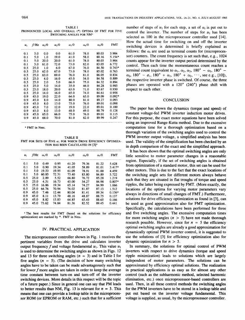
Fig. 17. As Fig. 16, but for PM, uI = - 0.5.
For Figs. 14 and 15 the FMT has been calculated as givenby (14). Integrating over the angle would result in much lowervalues in Figs. 14 and 15 for small ul because there also X issmall. Finally, Figs. 16 and 17 give a three-dimensional viewof the behavior of FMT.
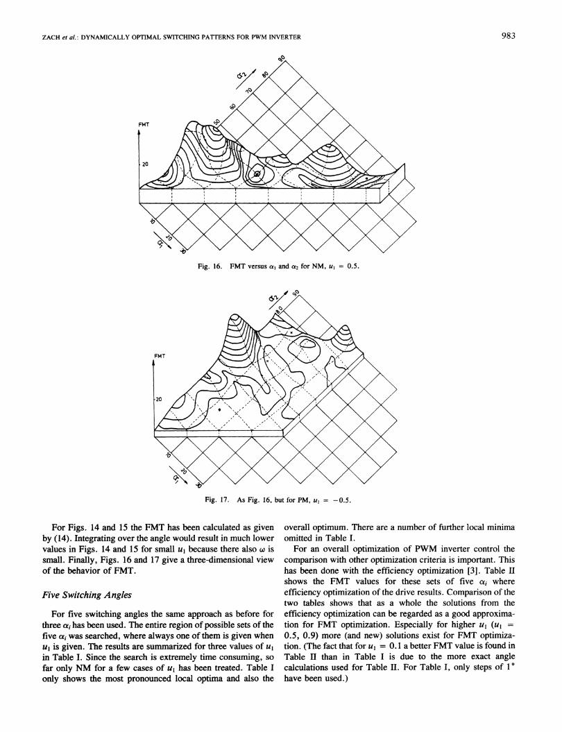
Five Switching Angles
For five switching angles the same approach as before fortiree ai has been used. The entire region of possible sets of thefive ai was searched, where always one of them is given whenul is given. The results are summarized for three values of ulin Table I. Since the search is extremely time consuming, sofar only NM for a few cases of ul has been treated. Table Ionly shows the most pronounced local optima and also the
overall optimum. There are a number of further local minimaomitted in Table I.
For an overall optimization of PWM inverter control thecomparison with other optimization criteria is important. Thishas been done with the efficiency optimization [3]. Table IIshows the FMT values for these sets of five a, whereefficiency optimization of the drive results. Comparison of thetwo tables shows that as a whole the solutions from theefficiency optimization can be regarded as a good approxima-tion for FMT optimization. Especially for higher ul (ul =
0.5, 0.9) more (and new) solutions exist for FMT optimiza-tion. (The fact that for ul = 0.1 a better FMT value is found inTable II than in Table I is due to the more exact anglecalculations used for Table II. For Table I, only steps of 10have been used.)
983
IEEE TRANSACTIONS ON INDUSTRY APPLICATIONS. VOL. IA-21, NO. 4, JULY/AUGUST 1985
TABLE IPRONOUNCED LOCAL AND OVERALL (*) OPTIMA OF FMT FOR FIVE
SWITCHING ANGLES FOR NMa
ul f/Hz ca/0 c02/0 a3/0 a4/0 a5/O FMT
0.1 5.0 0.0 0.0 61.0 78.0 80.03 5.9040.1 5.0 1.0 19.0 41.0 58.0 80.16 5.154*0.1 5.0 20.0 20.0 61.0 78.0 80.03 5.9040.1 5.0 61.0 72.0 73.0 82.0 83.05 6.7720.5 25.0 1.0 6.0 67.0 76.0 84.50 0.743*0.5 25.0 62.0 67.0 73.0 78.0 85.02 0.7630.5 25.0 63.0 69.0 76.0 81.0 86.05 0.8340.5 25.0 4.0 16.0 45.0 54.0 84.58 0.8890.5 25.0 2.0 5.0 66.0 75.0 84.32 0.8940.5 25.0 5.0 14.0 35.0 46.0 84.28 0.9850.5 25.0 18.0 20.0 63.0 71.0 83.67 0.9300.5 25.0 14.0 16.0 65.0 74.0 84.61 0.9580.9 45.0 19.0 22.0 64.0 65.0 89.09 0.092*0.9 45.0 8.0 14.0 80.0 81.0 89.27 0.0930.9 45.0 8.0 13.0 75.0 76.0 89.01 0.0980.9 45.0 7.0 12.0 19.0 22.0 89.01 0.1000.9 45.0 8.0 13.0 48.0 49.0 88.79 0.1280.9 45.0 65.0 66.0 75.0 76.0 89.01 0.1150.9 45.0 68.0 70.0 81.0 82.0 89.99 0.247
a FMT in Nms.
TABLE IIFMT FOR SETS OF FIVE a; FOR WHICH DRIVE EFFICIENCY OPTIMIZA-
TION HAS BEEN CALCULATED IN [3]1
U fl/Hz a1/0 a2/0 CY3/0 a4/0 (X5/0 FMT
0.1 5.0 0.49 0.95 61.20 79.36 81.22 5.6280.1 5.0 0.90 19.34 41.05 58.89 81.01 3.417*0.1 5.0 19.53 19.95 61.09 78.91 81.00 4.4590.1 5.0 60.85 72.31 73.40 83.80 84.89 5.7220.5 25.0 2.89 5.52 66.80 76.72 85.28 1.2190.5 25.0 4.51 16.73 45.00 54.27 84.98 0.807*0.5 25.0 16.86 19.34 65.14 74.27 84.99 1.0660.5 25.0 64.76 70.94 76.02 81.87 87.13 1.5120.9 45.0 7.46 12.44 80.04 81.41 89.34 0.136*0.9 45.0 8.11 13.79 48.16 48.87 88.75 0.1370.9 45.0 8.82 13.83 64.85 65.43 88.65 0.1660.9 45.0 73.62 74.84 81.36 82.52 89.45 0.441
a The best results for FMT (based on the solutions for efficiencyoptimization) are marked by *. FMT in Nms.
IV. PRACTICAL APPLICATION
The microprocessor controller shown in Fig. 1 receives thepertinent variables from the drive and calculates inverteroutput frequency f and voltage fundamental u1. This value uIis used to determine the switching angles as shown in Figs. 12and 13 for three switching angles (n = 3) and in Table I forfive angles (n = 5). (The decision of how many switchingangles have to be taken can be made advantageously such thatfor lowerfmore angles are taken in order to keep the averagetime constant between turn-on and turn-off of the inverterswitching devices. More details in this respect will be the topicof a future paper.) Since in general one can say that PM leadsto better results than NM, Fig. 13 is relevant for n = 3. Thismeans that one can provide a lookup table in the microproces-sor ROM (or EPROM or RAM, etc.) such that for a sufficient
number of steps of ul for each step, a set of cxi is put out tocontrol the inverter. The number of steps for u, has beenselected as 100 in the microprocessor controller used [14].How the actual time for switching on and off the inverterswitching devices is determined is briefly explained asfollows: the aii are used as terminal counts for (microproces-sor) counters. The count frequency is set such that, e.g., 1024counts appear for the inverter output period determined by thecontrol. Then each time the momentaneous count reaches aterminal count (equivalent to a1, a12, a3, 1800 - a3, 180° -
a12, 1800 - a1, 1800 + a,, 1800 + a2, * - , see e.g., [10]),the respective inverter phase is switched. Of course, the threephases are operated with a 1200 (2400) phase shift withrespect to each other.
CONCLUSION
The paper has shown the dynamics (torque and speed) ofconstant voltage-fed PWM inverter induction motor drives.For this purpose, the exact motor equations have been solvedusing an improved Runge-Kutta method. Due to the excessivecomputation time for a thorough optimization based on athorough variation of the switching angles used to control thePWM inverter output voltage, a simplified analysis has beenused. The validity of the simplification has been checked by anin depth comparison of the exact and the simplified approach.
It has been shown that the optimal switching angles are onlylittle sensitive to motor parameter changes in a reasonableregion. Especially, if the set of switching angles is obtainedfrom optimization of a standard motor, this set can be used forother motors. This is due to the fact that the exact locations ofthe switching angle sets for different motors always behavesuch that they are situated in flat troughs of torque and speedripples, the latter being expressed by FMT. (More exactly, thelocations of the optima for varying motor parameters varyalways in directions of small changes of FMT.) Furthermore,solutions for drive efficiency optimization as found in [3], canbe used as good approximation also for FMT optimization.Specifically, the calculations have been performed for threeand five switching angles. The excessive computation timesfor more switching angles (n > 5) have not made thoroughresearch possible. However, since for n = 5 the efficiencyoptimal switching angles are already a good approximation fordynamically optimal PWM inverter control, it is suggested touse the solutions of [3] for efficiency optimization also fordynamic optimization for n > 5.
In summary, the solutions for optimal control of PWMinverters with respect to drive dynamics (torque and speedripple minimization) leads to solutions which are largelyindependent of motor parameters. The solutions can beapproximated by efficiency optimal solutions. The realizationin practical applications is as easy as for almost any othercontrol (such as the subharmonic method, selected harmonicelimination, etc.) once microprocessor-based controllers areused. Then, in all these control methods the switching anglesfor the PWM inverters have to be stored in a lookup table andput out based on the inverter voltage fundamental. Thisvoltage is supplied, as usual, by the microprocessor controller.
984
ZACH et al.: DYNAMICALLY OPTIMAL SWITCHING PATTERNS FOR PWM INVERTER
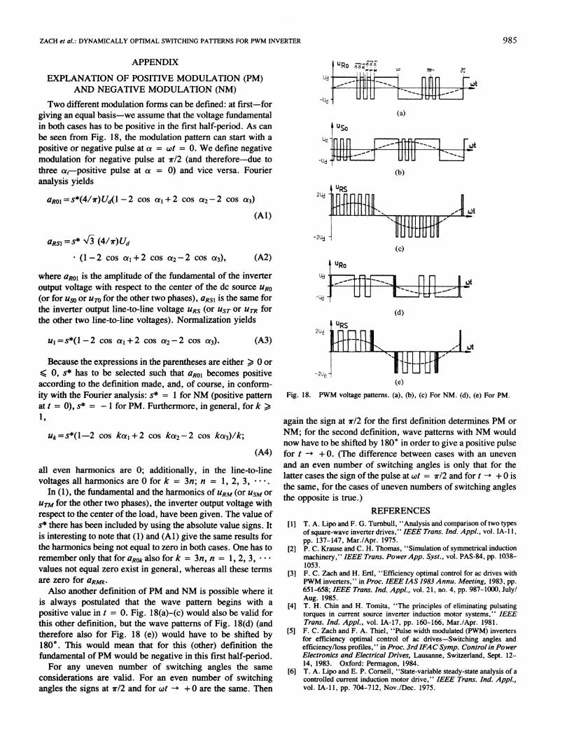
APPENDIX
EXPLANATION OF POSITIVE MODULATION (PM)AND NEGATIVE MODULATION (NM)
Two different modulation forms can be defined: at first-forgiving an equal basis-we assume that the voltage fundamentalin both cases has to be positive in the first half-period. As canbe seen from Fig. 18, the modulation pattern can start with apositive or negative pulse at a = wt = 0. We define negativemodulation for negative pulse at 7r/2 (and therefore-due tothree a(-positive pulse at a = 0) and vice versa. Fourieranalysis yields
aRoI =s*(4/1r)Ud(l-2 cos a, + 2 cos Ca2-2 cos C3)
(Al)
aRSI =S* V3 (4/7r)Ud
* (1-2 cos a1+ 2 cos a22-2 cos C3),
Ud .
-Ud
(a)
Ud -
-Ud .
2ud
-2Ud
(A2)
where aRol is the amplitude of the fundamental of the inverteroutput voltage with respect to the center of the dc source URO(or for uso or um for the other two phases), aRS1 is the same forthe inverter output line-to-line voltage URS (or UST or UTR forthe other two line-to-line voltages). Normalization yields
2ud
ul-s*(l-2 cos a, + 2 cos 0a2-2 cos a13).
LUd
-Ud -1
(A3)
Because the expressions in the parentheses are either > 0 or. 0, s* has to be selected such that aRo1 becomes positiveaccording to the definition made, and, of course, in conform-ity with the Fourier analysis: s* = 1 for NM (positive patternat t = 0), s* = -1 for PM. Furthermore, in general, for k >1,
Uk=S*(l 2 cos kaI+2 cos kai2-2 cos ka3)/k;
(A4)
all even harmonics are 0; additionally, in the line-to-linevoltages all harmonics are 0 for k = 3n; n = 1, 2, 3,
In (1), the fundamental and the harmonics of URM (or USM orUTM for the other two phases), the inverter output voltage withrespect to the center of the load, have been given. The value ofs* there has been included by using the absolute value signs. Itis interesting to note that (1) and (Al) give the same results forthe harmonics being not equal to zero in both cases. One has toremember only that for aROk-also for k = 3n, n = 1, 2, 3, * - -
values not equal zero exist in general, whereas all these termsare zero for aRMk.
Also another definition of PM and NM is possible where itis always postulated that the wave pattern begins with apositive value in t = 0. Fig. 18(a)-(c) would also be valid forthis other definition, but the wave patterns of Fig. 18(d) (andtherefore also for Fig. 18 (e)) would have to be shifted by1800. This would mean that for this (other) definition thefundamental of PM would be negative in this first half-period.
For any uneven number of switching angles the sameconsiderations are valid. For an even number of switchingangles the signs at 7r/2 and for wt -+ +0 are the same. Then
-2Ud -
USo
il [T1FrT -i UUU .1---
(b)
(c)
URo
[_--tfl-7
Lot
nn Rot-U U I.JI- h.]1L
(d)IURS
- 1 '
(e)
Fig. 18. PWM voltage patterns. (a), (b), (c) For NM. (d), (e) For PM.
again the sign at 7r/2 for the first definition determines PM orNM; for the second definition, wave patterns with NM wouldnow have to be shifted by 1800 in order to give a positive pulsefor t --+0. (The difference between cases with an unevenand an even number of switching angles is only that for thelatter cases the sign of the pulse at wt = 7r/2 and for t +0 isthe same, for the cases of uneven numbers of switching anglesthe opposite is true.)
REFERENCES[1] T. A. Lipo and F. G. Tumbull, "Analysis and comparison of two types
of square-wave inverter drives," IEEE Trans. Ind. Appl., vol. IA-i 1,pp. 137-147, Mar./Apr. 1975.
[2] P. C. Krause and C. H. Thomas, "Simulation of symmetrical inductionmachinery," IEEE Trans. PowerApp. Syst., vol. PAS-84, pp. 1038-1053.
[3] F. C. Zach and H. Ertl, "Efficiency optimal control for ac drives withPWM inverters," in Proc. IEEE IAS 1983 Annu. Meeting, 1983, pp.651-658; IEEE Trans. Ind. Appl., vol. 21, no. 4, pp. 987-1000, July/Aug. 1985.
[4] T. H. Chin and H. Tomita, "The principles of eliminating pulsatingtorques in current source inverter induction motor systems," IEEETrans. Ind. Appl., vol. IA-17, pp. 160-166, Mar./Apr. 1981.
[5] F. C. Zach and F. A. Thiel, "Pulse width modulated (PWM) invertersfor efficiency optimal control of ac drives-Switching angles andefficiency/loss profiles," in Proc. 3rdIFACSymp. Control in PowerElectronics and Electrical Drives, Lausanne, Switzerland, Sept. 12-14, 1983. Oxford: Permagon, 1984.
[6] T. A. Lipo and E. P. Cornell, "State-variable steady-state analysis of acontrolled current induction motor drive," IEEE Trans. Ind. Appl.,vol. IA-Il, pp. 704-712, Nov./Dec. 1975.
985

IEEE TRANSACTIONS ON INDUSTRY APPLICATIONS, VOL. IA-21, NO. 4, JULY/AUGUST 1985
[7] T. A. Lipo, P. C. Krause, and H. E. Jordan, "Harmonic torque andspeed pulsations in a rectifier-inverter induction motor drive," IEEETrans. Power App. Syst., vol. PAS-88, pp. 579-587, May 1969.
[8] D. W. Novotny, "Steady-state performance of inverter fed inductionmachines by means of time domain complex variables," IEEE Trans.Power App. Syst., vol. PAS-95, pp. 927-935, May/June 1976.
[9] P. C. Krause, "Method of multiple reference frames applied to theanalysis of symmetrical induction machinery," IEEE Trans. PowerApp. Syst., vol. PAS-87, pp. 218-227, Jan. 1968.
[101 F. Zach, Power Electronics. New York: Springer-Verlag, 1979.[11] K. P. Kovacs and I. Racz, Transiente Vorgaenge in Wechselstrom-
maschinen. Budapest, Hungary: Verlag der Ung. Akademie derWissenschaften, 1959.
[12] B. K. Bose, Adjustable SpeedACDrive Systems. New York: IEEEPress, 1980.
[13] H. Kleinrath, "Das elektromechanische Verhalten der stromrichterges-peisten Asynchronmaschine," Arch. Elektrotechnik, vol. 57, pp.297-306, 1976.
[14] F. C. Zach, R. J. Berthold, and K. H. Kaiser, "General purposemicroprocessor modulator for a wide range ofPWM techniques for acmotor control," in Proc. IEEE Ind. Appl. Soc. 1982 Annu.Meeting, 1982, pp. 446-451.
[15] G. Hall and J. M. Watt, Modern Numerical Methods for OrdinaryDifferential Equations. Oxford, England: Clarendon Press, 1976.
Franz C. Zach (M'82) was born in Vienna,Austria, on December 5, 1942. He received theDipl.-Ing. (M.Sc.) and Ph.D. degrees (cum laude)from the University of Technology, Vienna, Aus-tria, in 1965 and 1968, respectively.From 1965 to 1969 he was a Scientific Assistant
in Vienna, and from 1969 to 1972 he was with theNASA Goddard Space Flight Center in Greenbelt,MD (Washington, DC). In 1972 he returned toAustria to become Associate Professor for PowerElectronics at the Vienna University of Technology.
There has has been heading the Power Electronics Group since 1974. He is theauthor of two books. His current activities lie in power electronics andassociated controls, especially as used for variable speed ac motor drives. Inthese areas he also is involved in extensive industrial work.
Roberto Martinez was born on May 30, 1948 inColombia. He received the B.S. degree from theUniversidad Industrial de Santander, Bucaramanga,Colombia, in 1973 and the Dipl.-Ing. (M.Sc.)degree in electrical engineering from the MunichInstitute of Technology in 1977. Since 1982 he hasbeen working toward the Ph.D. degree in the area ofoptimal PWM inverter drives at the University ofTechnology (Power Electronics Section) in Vienna,Austria.From 1978 to 1982 he was with the Universidad
Industrial de Santander as an Assistant in the Department of Electrical andElectronic Engineering.
Siegfried Keplinger was born on February 15,1958 in Linz, Upper Austria. He has been studyingelectrical engineering in Vienna since 1977 andexpects to receive the M.Sc. (Dipl.-Ing.) degree
-4 ~~ early in 1985.
Albert SeLser was born on March 24, 1960 inVienna, Austria. He has been studying electricalengineering in Vienna since 1978 and received theM.Sc. (Dipl.-Ing.) degree in March 1985.
986
Related Documents