Journal of Engineering Innovation and Research, Volume: IX, Issue:1, January-March 2019 29 ISSN 2230- 9373 Volume-IX , Issue-1 January-March, 2019 Dynamic Stability under Parametric Excitation of Functionally Graded Timoshenko FG beam Abhijit Mohanty 1 , Prof. R.R.Dash 2 Department of Mechanical Engineering, College of Engineering and Technology, Bhubaneswar, E-mail: [email protected] ABSTRACT Many failures of engineering structures have been attributed to structural instability, in which large deformations of the structures are observed. It is the nature of loading that characterizes the nature of the problem of structural stability to be solved. The loading may be either static or dynamic. Laminated composite materials attract the attention of designers due to their characteristics of high stiffness and strength to weight ratio. FGMs having gradual variation of properties are out of the problems of laminated composite materials and can replace them successfully. The conventional armours are manufactured having compromised with toughness. FGMs can be used for manufacturing modern armours without compromising with hardness of ceramics and toughness of metals. In this article an analysis involving critical buckling load, free vibration and dynamic stability of a functionally graded Timoshenko beam having properties along thickness of beam according to exponential and power law. Key words: FGM, Timoshenko beam, parametric excitation, FEM, Stability INTRODUCTION The dynamic stability of structures is a subject of considerable engineering importance and many investigations have been carried out in this regard. The study of behaviour of functionally graded materials (FGMs) has been an interesting topic of considerable research interest during the past decade. The intensity and rapid growth of research on this class of materials is actually due to their continuously varying material properties, which give great advantages over the conventional homogeneous and layered materials. The weakness of conventional laminated composite materials, such as debonding, huge residual stress, locally large plastic deformations can be eliminated by using FGM. FGMs are regarded as one of the most promising candidates for advanced composites in many engineering sectors such as the aerospace, aircraft, automobile and defence industries and most recently the electronic and the biomedical sectors. Application of FGM is gaining increasing importance in the aforesaid sectors, wherein, these components are subjected to vibration and dynamic stability. The blades of turbine, helicopter and spacecraft, rail etc. can be modelled as beams to investigate their dynamic behaviour. Iwatsubo et. al. [7] have calculated the regions of instability for columns by solving Mathieu equations obtained by applying Galerkin method to governing equations of motion. The effects of

Welcome message from author
This document is posted to help you gain knowledge. Please leave a comment to let me know what you think about it! Share it to your friends and learn new things together.
Transcript
Journal of Engineering Innovation and Research, Volume: IX, Issue:1, January-March 2019 29
ISSN 2230- 9373
Volume-IX , Issue-1
January-March, 2019
Dynamic Stability under Parametric Excitation of Functionally Graded
Timoshenko FG beam
Abhijit Mohanty1 , Prof. R.R.Dash2
Department of Mechanical Engineering, College of Engineering and Technology, Bhubaneswar,
E-mail: [email protected]
ABSTRACT
Many failures of engineering structures have been attributed to structural instability, in which large
deformations of the structures are observed. It is the nature of loading that characterizes the nature of
the problem of structural stability to be solved. The loading may be either static or dynamic. Laminated
composite materials attract the attention of designers due to their characteristics of high stiffness and
strength to weight ratio. FGMs having gradual variation of properties are out of the problems of
laminated composite materials and can replace them successfully. The conventional armours are
manufactured having compromised with toughness. FGMs can be used for manufacturing modern
armours without compromising with hardness of ceramics and toughness of metals. In this article an
analysis involving critical buckling load, free vibration and dynamic stability of a functionally graded
Timoshenko beam having properties along thickness of beam according to exponential and power law.
Key words: FGM, Timoshenko beam, parametric excitation, FEM, Stability
INTRODUCTION
The dynamic stability of structures is a subject of considerable engineering importance and
many investigations have been carried out in this regard. The study of behaviour of functionally graded
materials (FGMs) has been an interesting topic of considerable research interest during the past decade.
The intensity and rapid growth of research on this class of materials is actually due to their continuously
varying material properties, which give great advantages over the conventional homogeneous and
layered materials. The weakness of conventional laminated composite materials, such as debonding,
huge residual stress, locally large plastic deformations can be eliminated by using FGM. FGMs are
regarded as one of the most promising candidates for advanced composites in many engineering sectors
such as the aerospace, aircraft, automobile and defence industries and most recently the electronic and
the biomedical sectors. Application of FGM is gaining increasing importance in the aforesaid sectors,
wherein, these components are subjected to vibration and dynamic stability. The blades of turbine,
helicopter and spacecraft, rail etc. can be modelled as beams to investigate their dynamic behaviour.
Iwatsubo et. al. [7] have calculated the regions of instability for columns by solving Mathieu
equations obtained by applying Galerkin method to governing equations of motion. The effects of
Journal of Engineering Innovation and Research, Volume: IX, Issue:1, January-March 2019 30
internal and external damping on stability of the column are also determined. Abbas and Thomas [1],
Briseghella et. al. [5] and Ozturk and Sabuncu [9] have used finite element method to study the dynamic
stability of beams. Shastry and Rao [11] have compared the stability parameter of simply supported
beam and clamped beam for different locations of two symmetrically placed intermediate supports. It
is found that the stability parameter of simply supported beam approaches that of clamped beam when
the intermediate supports are placed at a distance equal to one eighth of beam length from ends. Zhu
and Shankar [12] have developed a method to solve two-dimensional elasticity equations for an FGM
beam. Fourier series method along with Galerkin method is used for the analysis. It has been shown
that the choice of polynomial for the variation of properties along the direction of thickness enables the
method to be applied to the functionally graded structures with arbitrary variation of properties. Lim et.
al. [8] have studied the static failure modes and load capabilities of foam core composite sandwich
beams both analytically and experimentally. Timoshenko beam has been derived from which the
governing equation for Rayleigh as well as for Euler-Bernoulli beam can be deduced analytically. Babai
et. al. [3], Gharib et. al. [6], and Benatta et. al. [4] have studied the static response of a functionally
graded beam under external excitation. Salai et. al. [10] have presented a theoretical analysis of FGM
beams using sigmoid function. Alshorbagy et. al. [6] have studied the dynamic characteristics of a
functionally graded Euler-Bernoulli beam applying principle of virtual work. Several models have been
compared by Arnaldo and Richard [11] have studied the effect of functionally graded materials on
resonance of bending shafts under time dependent axial loading.It is observed that metal-ceramic FGM
beams show substantial improvement in parametric resonance compared to metallic beams. The effects
of material composition, temperature dependent properties, slenderness ratio on thermal buckling and
vibration of functionally graded beams are investigated by Wattanasakulpong et al. [13]. The third order
shear deformation theory is considered by the authors.
It is learnt from the reported literature that FGMs have scope for numerous applications in
diversified fields. These materials should be predictable as regards their behaviour under parametric
resonance before use in related applications. The present chapter is devoted to the study of dynamic
stability of FG beams under parametric excitation.
FORMULATION
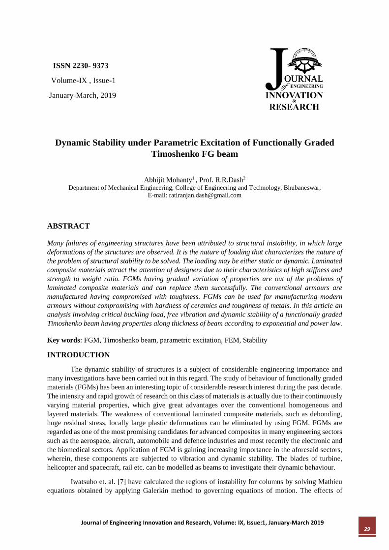
A functionally graded sandwich beam with top skin as alumina, bottom skin as steel and core as FGM
is shown in figure 1.(a). The beam, hinged at both the ends is subjected to a pulsating axial force P(t) =
Ps + Pt cos t , acting along its un-deformed axis. The static component of the axial force is sP . The
amplitude and frequency of the dynamic component of the force are tP and respectively, and t is
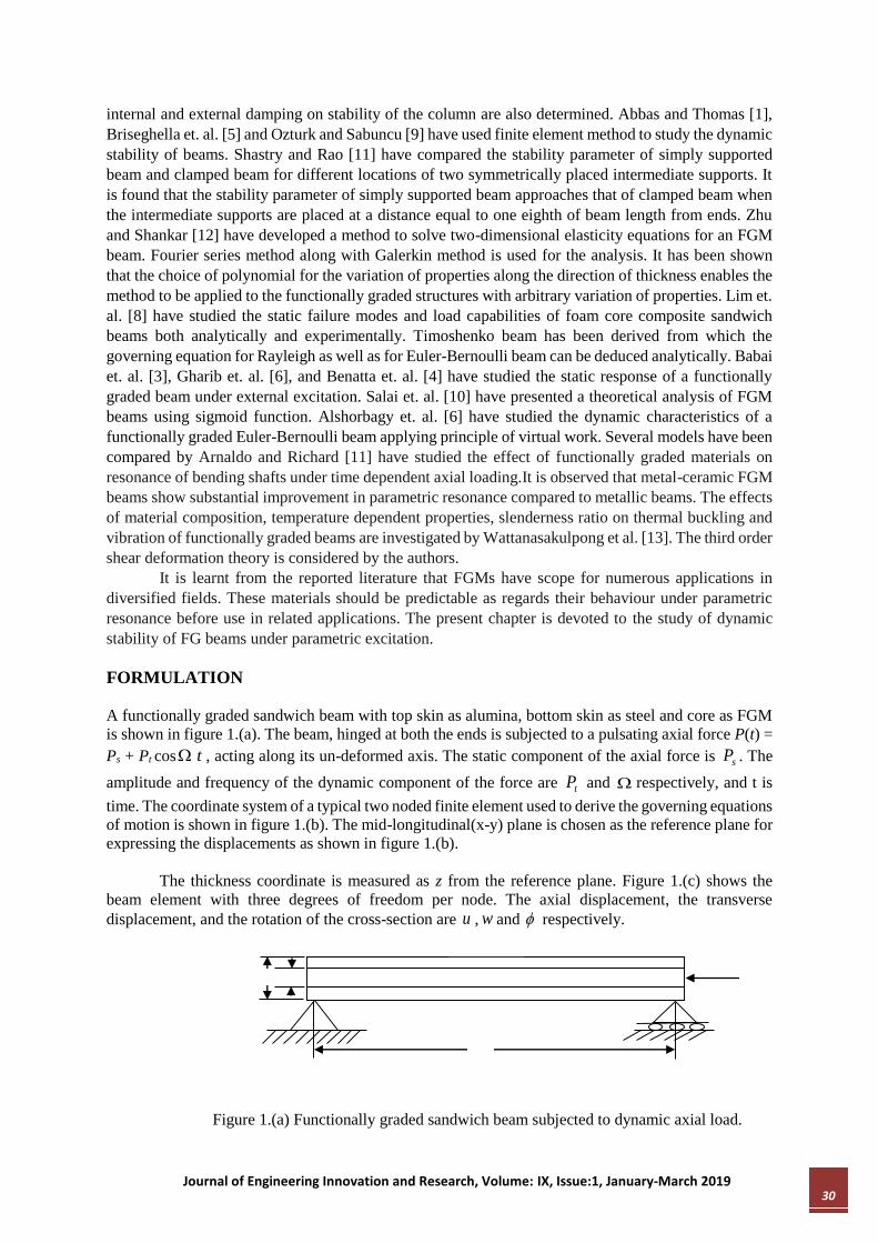
time. The coordinate system of a typical two noded finite element used to derive the governing equations
of motion is shown in figure 1.(b). The mid-longitudinal(x-y) plane is chosen as the reference plane for
expressing the displacements as shown in figure 1.(b).
The thickness coordinate is measured as z from the reference plane. Figure 1.(c) shows the
beam element with three degrees of freedom per node. The axial displacement, the transverse
displacement, and the rotation of the cross-section are u , w and respectively.
Figure 1.(a) Functionally graded sandwich beam subjected to dynamic axial load.
Journal of Engineering Innovation and Research, Volume: IX, Issue:1, January-March 2019 31
Figure 1(b) The coordinate system with generalized forces and displacements for the FGSW beam
element.
Figure 1.(c) Beam element showing generalized degrees of freedom for ith element.
The element matrices for the functionally graded beam element are derived. Moreover the same element
can be used for the analysis of a functionally graded ordinary beam by making the thickness of the skins
equal to zero.
Shape functions
The displacement fields considering first order shear deformation (Timoshenko beam theory) is
expressed as
),,(),,,(),,(),(),,,( txwtzyxWtxztxutzyxU (1)
The corresponding linear strains are expressed as
.,x
w
xz
x
uxzxx
(2)
The stress-strain relation in matrix form can be given by
xz
xx
xz
xx
zGk
zE
)0
0)( (3)
where xx and xx are normal stress and normal strains in x direction, xz and xz are shear stress and
shear strain in x-z plane. )(zE , )(zG and k are Young’s modulus, shear modulus along thickness and
shear correction factor respectively. The material properties of the FGM that varies along the thickness
of the beam are assumed to follow exponential law given by
b
tt
R
RehzeRzR log
2
1)),/21(exp()( (4)
and power law given by
b
n
bt Rh
zRRzR
2
1)()( , (5)
Journal of Engineering Innovation and Research, Volume: IX, Issue:1, January-March 2019 32
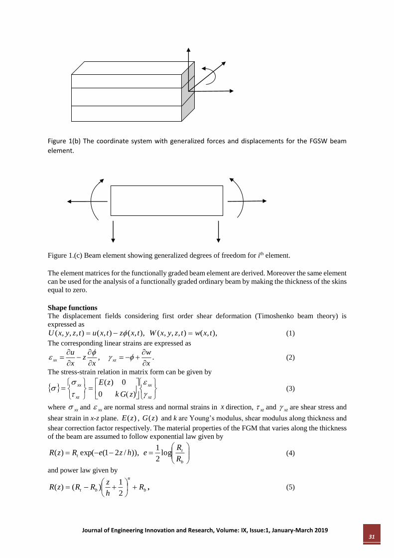
where, )(zR denotes a material property such as, E , G , etc., tR and bR denote the values of the
properties at topmost and bottommost layer of the beam respectively, and n is an index. The variation
of Young’s modulus along the thickness is shown in Figure 1.(d) for different laws and other properties
follow the same type of variation.
Figure 1.(d) Variation of Young’s modulus along thickness of steel-alumina FGM with steel-rich
bottom according to different laws
The kinetic energy T and the strain energy S of the beam element can be expressed as
dAdxt
W
t
UzT
l
A
22
0
)(2
1 (6)
l
A
xzxzxxxx dAdxS0
2
1 (7)
Using above equations the governing differential equation can be derived by applying Hamilton’s
principle which states that
2
1
0
t
t
dtST (8)
The governing differential equations in terms of the degrees of freedom u , w and can be written as
0)(
2
2
112
2
112
2
12
2
0
xB
x
uA
tI
t
uI
u
ST ,
0)(
2
2
552
2
0
xx
wA
t
wI
w
ST , and (9
0)(
552
2
112
2
112
2
12
2
2
x
wA
xD
x
uB
t
uI
tI
ST
-0.5 0 0.52
2.5
3
3.5
4x 10
11
z/h
Yo
un
g's
mo
du
lus E
(N
/m 2)
n=1
n=2
n=3
exp law
Es
Ea
Journal of Engineering Innovation and Research, Volume: IX, Issue:1, January-March 2019 33
where, dAzzzEDBAA
2
111111 1)( ,
dAzzzIIIA
2
210 1)( , and (10)
dAzGkAA
)(55
The shape functions for the displacement field for finite element formulation are obtained by solving
the static part of the eq. (8) with the following consideration.
,2
321 xaxaau
,3
7
2
654 xaxaxaaw
.2
1098 xaxaa
Using above equations an FEM model is developed by satisfying the imposed conditions.
Three shape functions for the axial, transverse and rotational degree of freedom is found out.
It is seen above that unlike the conventional elements the shape function not only depends on x and l
but it also depends on cross-sectional area and material properties which ensures better accuracy.
Moreover, better convergence can be achieved as the shape functions are obtained from the exact
solution of static part of the governing differential equation.
Similarly the Element elastic stiffness matrix and Element mass matrix are created using the general
force boundary conditions for the element can be given as
A
xxx
Bx
uAdAN
1111
A
xxzx
wAdAV 55
A
xxyx
Dx
uBdAzM
1111
(12)
where, N , zV , yM are axial force, shear force and bending moment respectively acting at the boundary
nodes.
When the axial load tP is applied on the beam element, the work done by the load can be
expressed as
l
p dxx
wtPW
0
2
2
1 (13)
The periodic solutions characterize the boundary conditions between the dynamic stability and
instability zones. So the periodic solution can be expressed as Fourier series.
A solution with period 2T is represented by:
Journal of Engineering Innovation and Research, Volume: IX, Issue:1, January-March 2019 34
..3,1 2cos
2sinˆ
K
kk
tKd
tKctU (14)
A solution with period T is represented by:
..4,2
02
cos2
sinˆ
K
kk
tKd
tKcctU (15)
On Simplification and Substitution the governing equation the condition for existence of these
boundary solutions with period 2T is given by
0ˆ4
2/2
UMKPK gdef (16)
Equation (48) represents an eigen value problem for known values of , d , and P . This equation
gives two sets of eigen values binding the regions of instability due to the presence of plus and
minus sign. The instability boundaries can be determined from the solution of the equation
04
2/2
MKPK gdef (17)
Free vibration
When =0, d =0, and 2 , eq. (17) is reduced to a problem of free vibration as
02 MKe (18)
The solution of eq. (16) gives the value of natural frequencies .
Static stability
When =1, d =0, and 0 , eq. (17) is reduced to the problem of static stability as
0
ge KPK (19)
The solution of eq. (19) gives the values of buckling loads.
Regions of instability
The fundamental natural frequency 1 and the critical buckling load P of an isotropic steel
beam with similar geometrical dimensions and end conditions as that of FGO beam are calculated from
eq. (18) and eq. (19) respectively.
Choosing 1
1
, eq. (17) can be rewritten as
04
2/2
1
2
1
MKPK gde
(20)
The solution of eq. (20) gives two sets of values of
1 for given values of , d ,
P , and 1 .
The plot between d and
1 gives the regions of dynamic instability.
Journal of Engineering Innovation and Research, Volume: IX, Issue:1, January-March 2019 35
RESULT AND DISCUSSION
The numerical study is carried out for a beam with pinned-pinned end conditions. An FG beam with
steel and alumina as its constituent phases is considered for the analysis followed by the investigation
of an FGSW beam made up of steel and alumina.
Validation of the formulation
In order to establish the correctness of calculation, the first five natural frequencies of a steel
aluminum FG beam are calculated. The dimensions of the beam are, Length, L=0.5m, breadth, b=0.1m
and thickness h=0.125m.
The FG beam reduces to a homogeneous beam when the value of power law index (n) is made
equal to zero. The critical buckling load parameter for various ( rL / ) ratios is computed and compared
with the result available in literature. Here, ‘ r ’ corresponds to radius of gyration.
Functionally graded beam
A steel-alumina FG beam with steel-rich bottom is considered for vibration and dynamic
stability analysis. The properties of constituent phases are:
Steel: E=2.1x10¹¹ Pa, G=0.8x10¹¹ Pa =7.85x10³kg/m3,
Alumina: E=3.9x10¹¹ Pa, G=1.37x10¹¹ Pa, =3.9x10³kg/m3, k=0.8667.
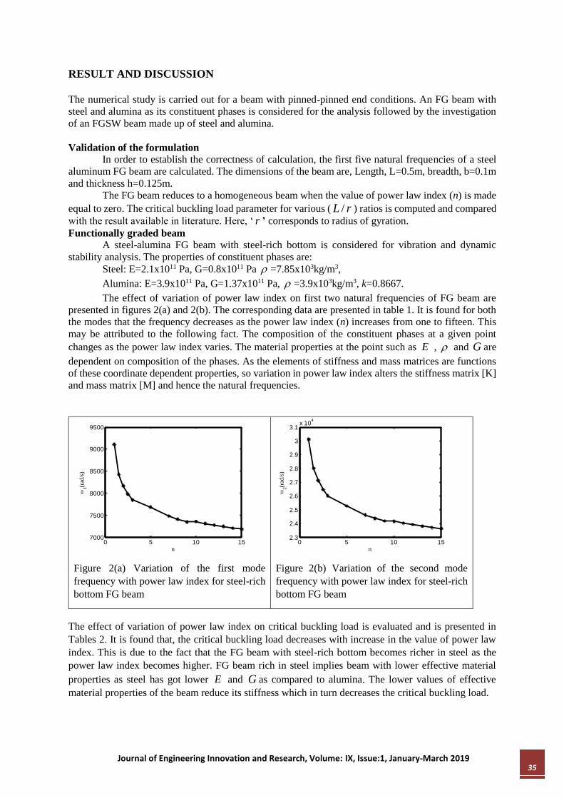
The effect of variation of power law index on first two natural frequencies of FG beam are
presented in figures 2(a) and 2(b). The corresponding data are presented in table 1. It is found for both
the modes that the frequency decreases as the power law index (n) increases from one to fifteen. This
may be attributed to the following fact. The composition of the constituent phases at a given point
changes as the power law index varies. The material properties at the point such as E , and G are
dependent on composition of the phases. As the elements of stiffness and mass matrices are functions
of these coordinate dependent properties, so variation in power law index alters the stiffness matrix [K]
and mass matrix [M] and hence the natural frequencies.
Figure 2(a) Variation of the first mode
frequency with power law index for steel-rich
bottom FG beam
Figure 2(b) Variation of the second mode
frequency with power law index for steel-rich
bottom FG beam
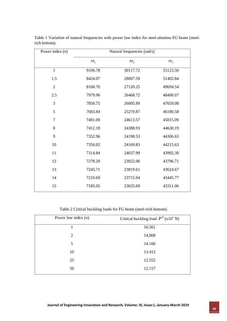
The effect of variation of power law index on critical buckling load is evaluated and is presented in
Tables 2. It is found that, the critical buckling load decreases with increase in the value of power law
index. This is due to the fact that the FG beam with steel-rich bottom becomes richer in steel as the
power law index becomes higher. FG beam rich in steel implies beam with lower effective material
properties as steel has got lower E and G as compared to alumina. The lower values of effective
material properties of the beam reduce its stiffness which in turn decreases the critical buckling load.
0 5 10 157000
7500
8000
8500
9000
9500
n
1(r
ad/s
)
0 5 10 152.3
2.4
2.5
2.6
2.7
2.8
2.9
3
3.1x 10
4
n
2(r
ad/s
)
Journal of Engineering Innovation and Research, Volume: IX, Issue:1, January-March 2019 36
Table 1 Variation of natural frequencies with power law index for steel-alumina FG beam (steel-
rich bottom).
Power index (n) Natural frequencies (rad/s)
1 2 3
1 9106.78 30117.72 55123.50
1.5 8424.07 28007.59 51402.84
2 8168.70 27120.25 49694.54
2.5 7979.96 26468.72 48490.07
3 7850.75 26005.89 47659.08
5 7683.84 25270.87 46180.58
7 7481.00 24613.57 45015.09
8 7412.18 24388.93 44630.19
9 7352.96 24198.53 44306.63
10 7356.02 24169.83 44215.63
11 7314.84 24037.99 43992.39
12 7278.29 23922.06 43796.71
13 7245.71 23819.61 43624.67
14 7210.69 23715.94 43445.77
15 7185.05 23635.69 43311.06
Table 2 Critical buckling loads for FG beam (steel-rich bottom).
Power law index (n) Critical buckling load P (x107 N)
1 16.561
2 14,908
5 14.166
10 13.412
25 12.552
50 12.157
Journal of Engineering Innovation and Research, Volume: IX, Issue:1, January-March 2019 37
The additional data for dynamic stability analysis are taken as follows. P =11.37x10⁷ N, 1 =6724.9
rad/s. P and 1 corresponds to the critical buckling load and fundamental natural frequency of a
homogenous steel beam of same dimensions and end conditions as of the FG beam.
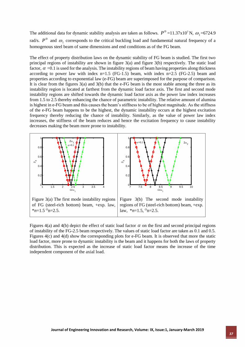
The effect of property distribution laws on the dynamic stability of FG beam is studied. The first two
principal regions of instability are shown in figure 3(a) and figure 3(b) respectively. The static load
factor, =0.1 is used for the analysis. The instability regions of beam having properties along thickness
according to power law with index n=1.5 (FG-1.5) beam, with index n=2.5 (FG-2.5) beam and
properties according to exponential law (e-FG) beam are superimposed for the purpose of comparison.
It is clear from the figures 3(a) and 3(b) that the e-FG beam is the most stable among the three as its
instability region is located at farthest from the dynamic load factor axis. The first and second mode
instability regions are shifted towards the dynamic load factor axis as the power law index increases
from 1.5 to 2.5 thereby enhancing the chance of parametric instability. The relative amount of alumina
is highest in e-FG beam and this causes the beam’s stiffness to be of highest magnitude. As the stiffness
of the e-FG beam happens to be the highest, the dynamic instability occurs at the highest excitation
frequency thereby reducing the chance of instability. Similarly, as the value of power law index
increases, the stiffness of the beam reduces and hence the excitation frequency to cause instability
decreases making the beam more prone to instability.
Figure 3(a) The first mode instability regions
of FG (steel-rich bottom) beam, +exp. law,
*n=1.5 On=2.5.
Figure 3(b) The second mode instability
regions of FG (steel-rich bottom) beam, +exp.
law, *n=1.5, On=2.5.
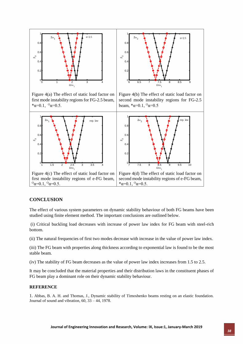
Figures 4(a) and 4(b) depict the effect of static load factor on the first and second principal regions
of instability of the FG-2.5 beam respectively. The values of static load factor are taken as 0.1 and 0.5.
Figures 4(c) and 4(d) show the corresponding plots for e-FG beam. It is observed that more the static
load factor, more prone to dynamic instability is the beam and it happens for both the laws of property
distribution. This is expected as the increase of static load factor means the increase of the time
independent component of the axial load.
1 1.5 2 2.5 3 3.5 40
0.2
0.4
0.6
0.8
1
/1
d
=0.1
21
7 7.5 8 8.5 9 9.5 100
0.2
0.4
0.6
0.8
1
/1
d
=0.1 22
Journal of Engineering Innovation and Research, Volume: IX, Issue:1, January-March 2019 38
Figure 4(a) The effect of static load factor on
first mode instability regions for FG-2.5 beam,
*α=0.1, Oα=0.5.
Figure 4(b) The effect of static load factor on
second mode instability regions for FG-2.5
beam, *α=0.1, Oα=0.5
Figure 4(c) The effect of static load factor on
first mode instability regions of e-FG beam, Oα=0.1, Oα=0.5.
Figure 4(d) The effect of static load factor on
second mode instability regions of e-FG beam,
*α=0.1, Oα=0.5.
CONCLUSION
The effect of various system parameters on dynamic stability behaviour of both FG beams have been
studied using finite element method. The important conclusions are outlined below.
(i) Critical buckling load decreases with increase of power law index for FG beam with steel-rich
bottom.
(ii) The natural frequencies of first two modes decrease with increase in the value of power law index.
(iii) The FG beam with properties along thickness according to exponential law is found to be the most
stable beam.
(iv) The stability of FG beam decreases as the value of power law index increases from 1.5 to 2.5.
It may be concluded that the material properties and their distribution laws in the constituent phases of
FG beam play a dominant role on their dynamic stability behaviour.
REFERENCE
1. Abbas, B. A. H. and Thomas, J., Dynamic stability of Timoshenko beams resting on an elastic foundation.
Journal of sound and vibration, 60, 33 – 44, 1978.
0 1 2 3 40
0.2
0.4
0.6
0.8
1
/1
d
n=2.521
6 6.5 7 7.5 8 8.5 90
0.2
0.4
0.6
0.8
1
/1
d
n=2.522
1 1.5 2 2.5 3 3.5 40
0.2
0.4
0.6
0.8
1
/1
d
exp. law21
7 7.5 8 8.5 9 9.5 100
0.2
0.4
0.6
0.8
1
/1
d
exp. law22
Journal of Engineering Innovation and Research, Volume: IX, Issue:1, January-March 2019 39
2. Aristizabal-Ochoa, J. D., Statics stability and vibration of non-prismatic beams and columns. Journal of Sound
and Vibration, 162(3), 441-455, 1993.
3. Babai, M. H., Abhasi, M. and Eslami, M. R., Coupled thermoelasticity of functionally graded beam. Journal of
Thermal Stresses, 31 (8), 680-697, 2008.
4. Benatta, M. A., Mechab, I., Tounsi, A. and Adda Bedia, E. A., Static analysis of functionally graded short
beams including warping and shear deformation effect. Computational Materials Science, 44, 765-773, 2008.
5. Briseghella, L., Majorana, C. E. and Pellegrino, C., Dynamic stability of elastic structures: a finite element
approach. Computers and Structures, 69, 11-25, 1998.
6. Gharib, A., Salehi, M. and Fazeli, S., Deflection control of functionally graded material beams with bounded
piezoelectric sensors and actuators. Material Science and Engineering A, 498, 110-114, 2008.
7. Iwatsubo, T., Sugiyama, Y. and Ogino, S., Simple and combination resonances of columns under periodic axial
loads. Journal of sound and vibration, 33, 211 – 221, 1974.
8. Lim, T. S., Lee, C. S. and Lee, D. G., Failure modes of foam core sandwich beams under static and impact
loads. Journal of Composite Materials, 38, 1639-1662, 2004.
9. Ozturk, H. and Sabuncu, M., Stability analysis of a cantilever composite beam on elastic support. Composite
Science and Technology, 65, 1982-1995, 2005.
10. Sallai, B. O., Tounsi, A., Mechab, I., Bachir B. M., Meradjah, M. and Adda, B. E. A., A theoretical analysis
of flexional bending of Al/Al2O3 S-FGM thick beams. Computational Materials Science, 44(4), 1344-1350, 2009.
11. Shastry, B. P. and Rao, G. V., Dynamic stability of columns with two symmetrically placed intermediate
supports. Journal of Sound and Vibration, 104(3), 524-527, 1986.
12. Young, T. H. and Gau, C. Y., Dynamic stability of spinning pretwisted beams subjected to axial random
forces. Journal of sound and Vibration, 268, 149-165, 2003.
13. Wattanasakul pong, N., Prusty, B. G. and Kelly, D. W., Thermal buckling and elastic vibration of third order
shear deformable functionally graded beams. International Journal of Mechanical Science, 53, 734-743, 2011.
Related Documents


