„Dynamic Simulation of Cylindrical Roller Bearings“ Von der Fakultät für Maschinenwesen der Rheinisch-Westfälischen Technischen Hochschule Aachen zur Erlangung des akademischen Grades eines Doktors der Ingenieurwissenschaften genehmigte Dissertation vorgelegt von Weihua Qian Berichter: Univ.-Prof. Dr.-Ing. Georg Jacobs Univ.-Prof. Marek Behr, Ph.D. Tag der mündlichen Prüfung: 13.12.2013 Diese Dissertation ist auf den Internetseiten der Hochschulbibliothek online verfügbar.

Welcome message from author
This document is posted to help you gain knowledge. Please leave a comment to let me know what you think about it! Share it to your friends and learn new things together.
Transcript
„Dynamic Simulation of Cylindrical Roller Bearings“
Von der Fakultät für Maschinenwesen der Rheinisch-Westfälischen Technischen Hochschule Aachen zur Erlangung des akademischen Grades eines
Doktors der Ingenieurwissenschaften genehmigte Dissertation
vorgelegt von
Weihua Qian
Berichter: Univ.-Prof. Dr.-Ing. Georg Jacobs Univ.-Prof. Marek Behr, Ph.D. Tag der mündlichen Prüfung: 13.12.2013 Diese Dissertation ist auf den Internetseiten der Hochschulbibliothek online verfügbar.

Preface This dissertation was written at Institute of Machine Element and Machine Design (IME) in RWTH Aachen University. I would like to thank the following persons:
Mr. Univ.-Prof. Dr.-Ing. G. Jacobs, who is the head of the institute, for accepting me as doctoral student and providing me an energetic and friendly team, his help, support and guidance during the past four years in IME. Univ.-Prof. M. Behr (Ph.D.) for his willingness to examine my doctoral thesis and participating in my oral exam. Univ.-Prof. Dr.-Ing. H. Murrendorf, for devoting his time as the chairman of the committee of my doctoral examination. Dr.-Ing. R. Schelenz, who is one of the chief engineers of the institute, for his valuable discussions about the projects and his friendliness.
Dr.-Ing. C. Hentschke, H. van. Lier, S. John, R. Augustino, S. Flock, J. Berroth, M. Wegerhoff, H. Jandrey, S. Kurutas, D. Witter, L. Bi, B. Juretzki, T. Kamper, D. Radner and other colleagues for their help and kindness.
Lastly I would like to appreciate my parents, who always give me encouragement and spiritual support.
Aachen, January 2014
Abstract In this work, a three-dimensional dynamic simulation model for cylindrical roller bearings is developed based on multi-body-simulation software SIMPACK and programming language FORTRAN. The aim of this work is to build a universal program to calculate the dynamic behavior of cylindrical roller bearings. This simulation model integrates major part of the functionalities according to the state of the art of existing programs which are: the slice model, the mutual influences of neighboring slices, the basic three-dimensional model, the calculation of lubricant film thickness and damping forces, the radial clearance, the roller-pocket clearance, the centrifugal forces and the hysteresis damping forces. The extended functionalities in this work can be summarized as follows:
1) Roller-pocket contact stiffness is taken into account and calculated with the help of finite element analysis.
2) The three types of cage guidance are modeled in details which are roller guidance, inner ring guidance and outer ring guidance.
3) The geometry of cage pocket is modeled for contact detection. 4) The elasticity of cage is built through importing the reduced finite element
models.
This extended model of cylindrical roller bearings is validated with the measurements and shows good agreement. Furthermore, for further plausibility of this model and also extension of the understanding of the dynamic behavior of cylindrical roller bearings such as roller slip, roller-pocket contact forces and cage mass center orbit, parameter variations in terms of different cage materials, cage guidance, radial clearances, roller-pocket clearances, are carried out. Lastly the bearing model is integrated in an existing multi-body-simulation model of a wind turbine namely in the main gearbox, in order to check the plausibility of this bearing model in wind turbines, based on the known behaviors of bearings. Through the further development of simulation model, the current established range of functions is extended. Thus the interpretation of bearings in engineering as well as the understanding of fundamental dynamic interactions during the design of cylindrical roller bearings is improved.
Zusammenfassung Im Rahmen dieser Arbeit wird ein dreidimensionales Simulationsmodell für Zylinderrollenlager, basierend auf der Mehrkörpersimulationssoftware SIMPACK und der Programmiersprache FORTRAN entwickelt. Das Ziel dieser Arbeit ist die Entwicklung eines universellen Programms zur Berechnung des dynamischen Verhaltens von Zylinderrollenlagern. Das Programm integriert den überwiegenden Teil der Funktionen wie beispielsweise das Scheibenmodell, die gegenseitigen Einflüsse von benachbarten Scheiben, das grundlegende dreidimensionale Simulationsmodell, die Berechnung der Schmierfilmhöhe und Dämpfungskräfte, das Radialspiel, das Spiel zwischen Wälzkörper und Käfigtasche, die Fliehkräfte und die Hysterese der Dämpfungskräfte gemäß Stand der Technik aus bestehenden Programmen. Die im Rahmen der vorgelegten Arbeit entstandenen Funktionserweiterungen können wie folgt zusammengefasst werden:
1) Die Wälzkörper-Tasche Kontaktsteifigkeiten werden berücksichtigt und mit Hilfe der Finite-Elemente-Analyse berechnet.
2) Die drei Typen von Käfigführungen, die Rollenführung, Innenringführung und Außenringführung werden detailliert modelliert.
3) Die Geometrie der Käfigtasche wird für die Kontakterkennung berücksichtigt. 4) Die Elastizität des Käfigs wird durch den Import reduzierter Finite-Elemente-
Modelle abgebildet.
Dieses erweiterte Modell des Zylinderrollenlagers wird mit Messungen validiert und zeigt eine gute Übereinstimmung. Außerdem werden zur weiteren Plausibilisierung des Modellverhaltens aber auch zur Erweiterung des Verständnisses des dynamischen Verhaltens von Zylinderrollenlagern - wie beispielsweise Schlupf des Wälzkörpers, Wälzkörper-Tasche Kontaktkräfte und Orbitalverhalten des Käfigs -Parametervariationen im Hinblick auf unterschiedliche Käfigmaterialien, Käfigführungen, Radialspiele sowie Spiele zwischen Wälzkörper und Käfigtasche durchgeführt. Schließlich wird das Lager-Modell in ein bestehendes MKS-Modell einer Windenergieanlage und zwar in das Hauptgetriebe der Anlage integriert, um eine Plausibilisierung des Lagermodells anhand bekannter Verhaltensweisen der Lager in Windenergieanlagen zu überprüfen. Durch die Weiterentwicklung des Simulationsmodells wird der heute etablierte Funktionsumfang erweitert und damit die Lagerauslegung in der Projektierung aber auch das Verständnis grundlegender dynamischer Wirkzusammenhänge bei der Entwicklung von Zylinderrollenlagern verbessert.
Symbols I
Contents
1 Introduction ........................................................................................................... 1 1.1 Research Background ...................................................................................... 1 1.2 State-of-the-art of Bearing Technology ........................................................... 4 1.2.1 Bearing Stiffness Evaluation ........................................................................ 4 1.2.2 Load Distribution between Roller and Raceway .......................................... 4 1.2.3 Friction Coefficient in EHL .......................................................................... 4 1.2.4 Optimization of Roller Profile ...................................................................... 5 1.2.5 Advanced Cage Design ................................................................................ 6 1.3 State-of-the-art of Multi-Body-Simulation ...................................................... 7 1.3.1 Introduction to Multi-Body-Simulation ....................................................... 7 1.3.2 Description of Physical Model ..................................................................... 7 1.3.3 Equations of Motion ..................................................................................... 8 1.3.4 Commercial MBS Programs ......................................................................... 8 1.3.5 Application of Multi-Body-Simulation ........................................................ 9 1.4 State-of-the-art of Bearing Simulation ........................................................... 10 1.4.1 Independent Bearing Calculation Program ................................................ 11 1.4.2 Redevelopment Based on MBS Software .................................................. 12 1.5 Problems in Existing Programs and Possible Solutions ................................ 13 1.6 Research Objectives ....................................................................................... 15
2 Fundamentals of Cylindrical Roller Bearings .................................................. 17 2.1 Classification of Cylindrical Roller Bearings ................................................ 17 2.2 Radial Clearance of Bearings ......................................................................... 18 2.3 Load Distribution within Bearings ................................................................. 19 2.4 Profile of Rollers ............................................................................................ 20 2.5 Kinematics in Cylindrical Roller Bearings .................................................... 22 2.6 Lubrication Regimes ...................................................................................... 23 2.7 Lubrication for Non-conformal Contacts ....................................................... 24 2.8 Determination of Friction Coefficients in Bearing ........................................ 25 2.9 Forces and Moments Acting on Roller .......................................................... 28 2.10 Bearing Damage ............................................................................................. 29 2.11 Chapter Summary .......................................................................................... 30
3 Modeling Bearing in SIMPACK ........................................................................ 31

Symbols II
3.1 System Flow Chart for Bearing Forces Calculation ...................................... 31 3.2 Attitudes of Roller against Rings ................................................................... 32 3.3 Calculation for Each Roller Slice ................................................................... 33 3.4 Outline of the Contacts within a Cylindrical Bearing .................................... 35 3.5 Roller-Raceway Contact ................................................................................ 35 3.5.1 Roller-raceway Contact Stiffness ............................................................... 35 3.5.2 Roller-raceway Contact Detection ............................................................. 39 3.5.3 Roller-Raceway Damping in Inlet Zone .................................................... 43 3.6 Roller-Pocket Contact .................................................................................... 47 3.6.1 Roller-Pocket Contact Stiffness ................................................................. 47 3.6.2 Roller-pocket Contact Detection ................................................................ 49 3.6.3 Roller-Pocket Squeeze Damping ................................................................ 54 3.7 Roller-Rib Contact ......................................................................................... 54 3.8 Cage Structural Stiffness ................................................................................ 55 3.9 Lubricant Squeeze Effect between Cage and Guiding Surface ..................... 59 3.10 Pocket and Cage Guidance Clearance ........................................................... 61 3.11 Drag Force Due to Lubricant ......................................................................... 62 3.12 Churning Moment Due to Lubricant .............................................................. 63 3.13 Material Hysteresis Damping ......................................................................... 64 3.14 Key Parameters Extraction ............................................................................. 65 3.15 Communications between FORTRAN and SIMPACK ................................. 66 3.16 Chapter Summary .......................................................................................... 67
4 Validation of CyBeSime ...................................................................................... 69 4.1 Cage Mass Center Orbit Compared with Measurements ............................... 69 4.2 Validation of Roller-Pocket Contact Mechanism .......................................... 70 4.3 Influence of Shaft Speed on Roller Slip......................................................... 73 4.4 Bearing Behavior under Excitation ................................................................ 74 4.5 Validation of Elastic Cage Model .................................................................. 78 4.6 Validation of Cage Instability ........................................................................ 81 4.7 Chapter Summary .......................................................................................... 87
5 Other Results of Single Bearing Simulation ..................................................... 88 5.1 Bearing Behavior under Aligned Load .......................................................... 88 5.2 Bearing Behavior under Misaligned Load ..................................................... 89 5.3 Minimum Radial Load for Eliminating Roller Slip in Load-zone ................. 92
Symbols III
5.4 Parameter Variations ...................................................................................... 93 5.4.1 Influence of Different Radial Loads ........................................................... 94 5.4.2 Influence of Different Radial Clearances ................................................... 95 5.4.3 Influence of Different Cage Materials ........................................................ 96 5.4.4 Influence of Roller Profiles ........................................................................ 98 5.4.5 Influence of Different Types of Cage Guidance ........................................ 99 5.4.6 Influence of Different Pocket Clearances ................................................. 101 5.5 Chapter Summary ........................................................................................ 102
6 Application in Wind Turbine Gearbox ........................................................... 104 6.1 Integrate CyBeSime in the Gearbox of a Wind Turbine .............................. 104 6.2 Discussion of Simulation Results ................................................................ 106 6.3 Chapter Summary: ....................................................................................... 112
7 Summary and Conclusion ................................................................................. 114
8 Outlook ............................................................................................................... 117
9 Literature ........................................................................................................... 118
10 Appendix ............................................................................................................ 126
Symbols IV
Symbols Symbols Meanings Units [] A Surface area covered by lubricant m²
aC Axial clearance m
DC Drag coefficient on cylindrical surface -
rC Radial clearance m
EHDD Elastohydrodynamic lubrication damping N·s/m
hD Material hysteresis damping N·s/m
kjD , Distance between two slices m
pD Bearing pitch diameter m
rD Roller diameter m
aF Axial roller-rib contact force N
adpF Axial damping force N
dragF Drag force on cylindrical surface N G Dimensionless material parameter -
sH Hersey number -
FEMK FE calculated stiffness N/m L Roller length m
äqL Effective contact length m
cM Churning moment N·m )( ixP Roller profile function m
iQ Roller-inner raceway load N
oQ Roller-outer raceway load N
dR Half width of roller in lubricant m
eR Reynolds number -
raR Roughness of raceway m
roR Roughness of roller m
aT Taylor number -
cT Cage thickness m U Dimensionless speed parameter - W Dimensionless load parameter -
eα Hysteresis coefficient s/m
pα Pressure viscosity coefficient 1/Pa
Symbols V
ic Elastic compliance btw. roller and inner ring -
oc Elastic compliance btw. roller and outer ring -
af Axial friction force between roller and ring N
f̂ Friction factor -
ch Central film thickness m
fh Film thickness m
minh Minimum film thickness m j Slice j - p Contact pressure N/ m²
Dq Load per slice of roller N r Rolling body radius in lubricant m
cs Slip ratio of cage -
rs Slip ratio of roller - t Housing + outer ring thickness m
jiw , Weighting coefficient -
bdμ Friction coefficient for boundary lubrication -
hdμ Friction coefficient for hydrodynamic lubrication -
rμ Friction coefficient -
Σ u Sum of surface velocity m/s ω Rolling body rotational speed in lubricant rad/s
cω Cage theoretical rotational speed rad/s
caω Cage actual rotational speed rad/s
irω Inner ring speed rad/s
rω Roller theoretical rotational speed rad/s
raω Roller actual rotational speed rad/s Λ Lubricant film parameter -
bΛ Film parameter for boundary lubrication -
hΛ Film parameter for hydrodynamic lubrication - jΔ Deflection on slice j m
ρ Lubricant density Kg/ m3 τ Shear stress N/ m²

Symbols VI
Introduction 1
1 Introduction
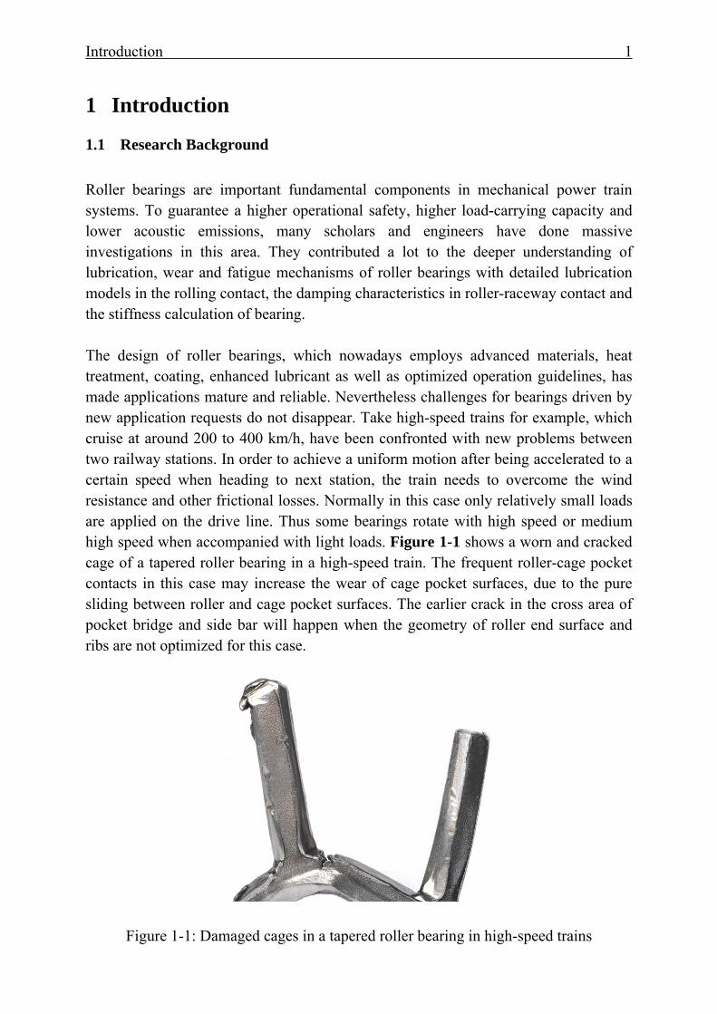
1.1 Research Background Roller bearings are important fundamental components in mechanical power train systems. To guarantee a higher operational safety, higher load-carrying capacity and lower acoustic emissions, many scholars and engineers have done massive investigations in this area. They contributed a lot to the deeper understanding of lubrication, wear and fatigue mechanisms of roller bearings with detailed lubrication models in the rolling contact, the damping characteristics in roller-raceway contact and the stiffness calculation of bearing. The design of roller bearings, which nowadays employs advanced materials, heat treatment, coating, enhanced lubricant as well as optimized operation guidelines, has made applications mature and reliable. Nevertheless challenges for bearings driven by new application requests do not disappear. Take high-speed trains for example, which cruise at around 200 to 400 km/h, have been confronted with new problems between two railway stations. In order to achieve a uniform motion after being accelerated to a certain speed when heading to next station, the train needs to overcome the wind resistance and other frictional losses. Normally in this case only relatively small loads are applied on the drive line. Thus some bearings rotate with high speed or medium high speed when accompanied with light loads. Figure 1-1 shows a worn and cracked cage of a tapered roller bearing in a high-speed train. The frequent roller-cage pocket contacts in this case may increase the wear of cage pocket surfaces, due to the pure sliding between roller and cage pocket surfaces. The earlier crack in the cross area of pocket bridge and side bar will happen when the geometry of roller end surface and ribs are not optimized for this case.
Figure 1-1: Damaged cages in a tapered roller bearing in high-speed trains
Introduction 2
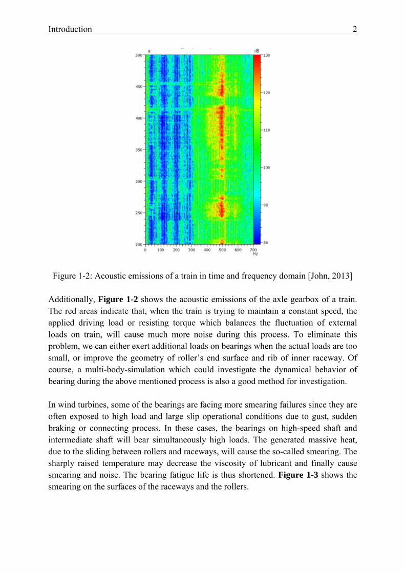
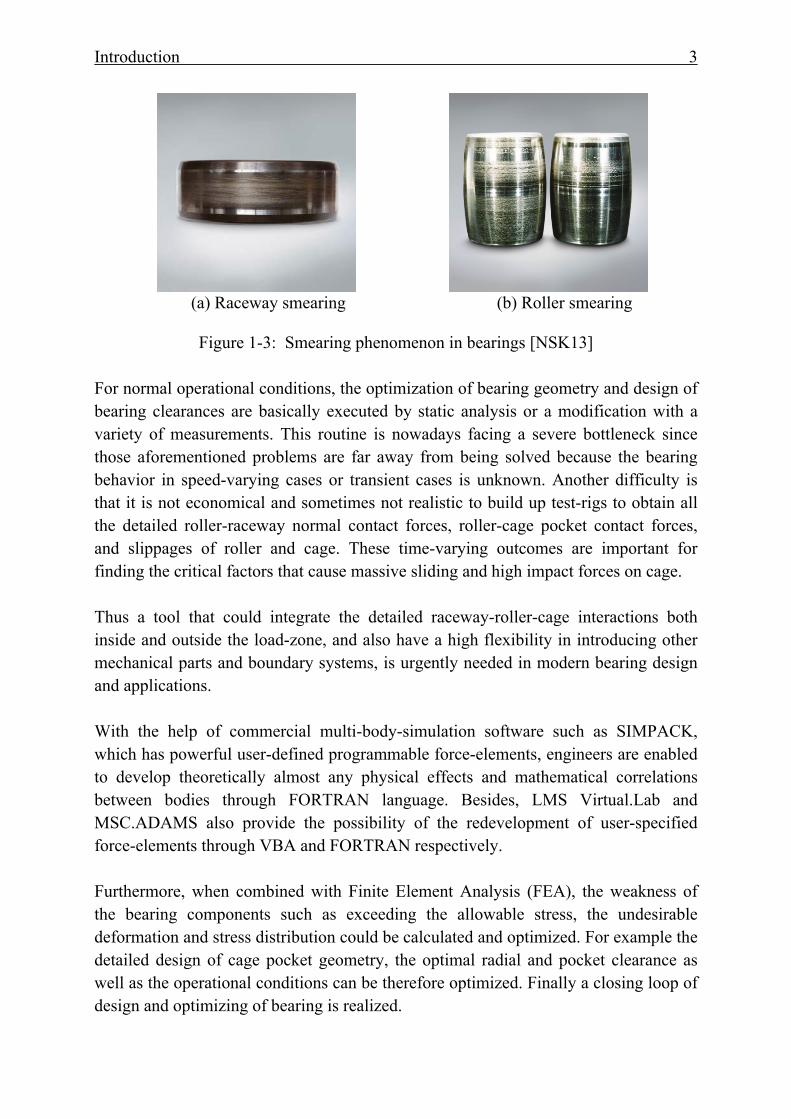
Figure 1-2: Acoustic emissions of a train in time and frequency domain [John, 2013] Additionally, Figure 1-2 shows the acoustic emissions of the axle gearbox of a train. The red areas indicate that, when the train is trying to maintain a constant speed, the applied driving load or resisting torque which balances the fluctuation of external loads on train, will cause much more noise during this process. To eliminate this problem, we can either exert additional loads on bearings when the actual loads are too small, or improve the geometry of roller’s end surface and rib of inner raceway. Of course, a multi-body-simulation which could investigate the dynamical behavior of bearing during the above mentioned process is also a good method for investigation. In wind turbines, some of the bearings are facing more smearing failures since they are often exposed to high load and large slip operational conditions due to gust, sudden braking or connecting process. In these cases, the bearings on high-speed shaft and intermediate shaft will bear simultaneously high loads. The generated massive heat, due to the sliding between rollers and raceways, will cause the so-called smearing. The sharply raised temperature may decrease the viscosity of lubricant and finally cause smearing and noise. The bearing fatigue life is thus shortened. Figure 1-3 shows the smearing on the surfaces of the raceways and the rollers.
Introduction 3
(a) Raceway smearing (b) Roller smearing
Figure 1-3: Smearing phenomenon in bearings [NSK13]
For normal operational conditions, the optimization of bearing geometry and design of bearing clearances are basically executed by static analysis or a modification with a variety of measurements. This routine is nowadays facing a severe bottleneck since those aforementioned problems are far away from being solved because the bearing behavior in speed-varying cases or transient cases is unknown. Another difficulty is that it is not economical and sometimes not realistic to build up test-rigs to obtain all the detailed roller-raceway normal contact forces, roller-cage pocket contact forces, and slippages of roller and cage. These time-varying outcomes are important for finding the critical factors that cause massive sliding and high impact forces on cage. Thus a tool that could integrate the detailed raceway-roller-cage interactions both inside and outside the load-zone, and also have a high flexibility in introducing other mechanical parts and boundary systems, is urgently needed in modern bearing design and applications. With the help of commercial multi-body-simulation software such as SIMPACK, which has powerful user-defined programmable force-elements, engineers are enabled to develop theoretically almost any physical effects and mathematical correlations between bodies through FORTRAN language. Besides, LMS Virtual.Lab and MSC.ADAMS also provide the possibility of the redevelopment of user-specified force-elements through VBA and FORTRAN respectively. Furthermore, when combined with Finite Element Analysis (FEA), the weakness of the bearing components such as exceeding the allowable stress, the undesirable deformation and stress distribution could be calculated and optimized. For example the detailed design of cage pocket geometry, the optimal radial and pocket clearance as well as the operational conditions can be therefore optimized. Finally a closing loop of design and optimizing of bearing is realized.
Introduction 4
This research work is aimed to develop a three dimensional cylindrical roller bearing simulation program, which allows arbitrary geometry definition in body-modeling stages, integrates explicit load-deflection relationship in roller raceway contact, lubricant and material hysteresis damping, roller profile, centrifugal forces and elasticity of cage. The solver of selected multi-body-simulation software will solve the differential equations. The post-processor enables the users to access those interested outputs and the animation of bearing movements such as cage mass center orbit. Lastly the resulting slips of roller and cage can be obtained which are quite valuable for guiding the bearing design and operation adjustments.
1.2 State-of-the-art of Bearing Technology
1.2.1 Bearing Stiffness Evaluation Bearing stiffness is an important performance characteristic. Thus a single contact needs to be studied. Although Heinrich Hertz gave an analytical solution for the point contact, the explicit load-deflection relationship for line contact is still unknown. Many researchers have developed their own curve-fit equations. Those equations that developed by Palmgren, Kunert, and Houpert have established an explicit correlation between load and resulting deflection [Pal59][Kun61][Hou01a][Hou01b]. Since the stiffness calculation for a single contact is addressed, the overall bearing stiffness between inner raceway and outer raceway in load-zone could be derived. Finally this could be very useful for the dynamical simulation of bearings due to its fastness in calculating the resulting forces with given geometrical deflection and vice versa.
1.2.2 Load Distribution between Roller and Raceway
In order to consider the misalignment of load in line contact, the rollers of a rolling bearing are imagined to have many discrete slices. For each slice the load-deflection relationship comes from curve-fits mentioned in the last section. Thus the first approximation is achieved. However, the mutual influences of adjacent slices are neglected. Teutsch et al. advocated a so-called Alternative Slice Technique to take that influences into account, which could obtain a good load distribution along the contact length between roller and raceway [TS04]. This is quite useful for multi-body-simulation because a fast load distribution calculation along the roller length is achieved.
1.2.3 Friction Coefficient in EHL
Introduction 5
Lubricants are commonly used in bearings for dissipating heat and reduce the friction forces among all contacting surfaces. The friction coefficients between roller and raceway, roller and cage pocket are the major two important variables that affect the dynamical behavior of bearings. Therefore, a proper calculation of friction coefficient for different lubrication regimes is critical. Basically when a type of lubricant is selected for usage, its traction behavior could be determined by experiments when the temperature in the inlet zone, rolling velocities and normal loads are given in elastohydrodynamic lubrication. Wang et al. tested two aviation lubricating oils with various loads, rolling velocities and lubricant inlet temperatures. After regression analysis of experimental data, an empirical equation could be obtained for predicting the traction coefficient versus slide-to-roll ratio curves [WYW04]. This is a quite useful alternative in fast deciding the traction coefficient between roller-raceway contacts in elastohydrodynamic lubrication.
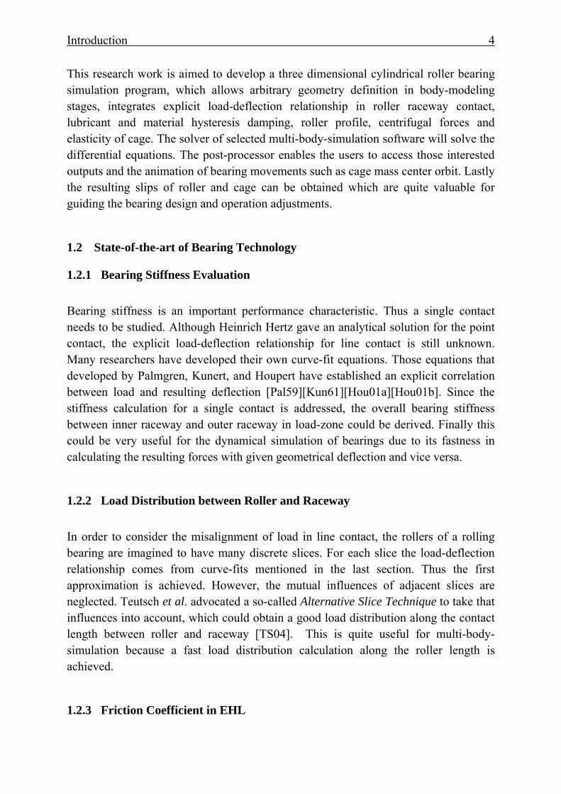
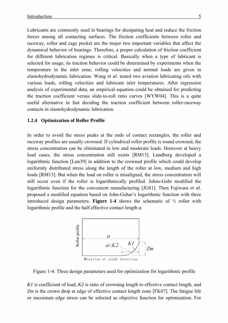
1.2.4 Optimization of Roller Profile In order to avoid the stress peaks at the ends of contact rectangles, the roller and raceway profiles are usually crowned. If cylindrical roller profile is round crowned, the stress concentration can be eliminated in low and moderate loads. However at heavy load cases, the stress concentration still exists [RM13]. Lundberg developed a logarithmic function [Lun39] in addition to the crowned profile which could develop uniformly distributed stress along the length of the roller at low, medium and high loads [RM13]. But when the load on roller is misaligned, the stress concentration will still occur even if the roller is logarithmically profiled. Johns-Gohr modified the logarithmic function for the convenient manufacturing [JG81]. Then Fujiwara et al. proposed a modified equation based on John-Gohar’s logarithmic function with three introduced design parameters. Figure 1-4 shows the schematic of ½ roller with logarithmic profile and the half effective contact length a.
Figure 1-4: Three design parameters used for optimization for logarithmic profile K1 is coefficient of load, K2 is ratio of crowning length to effective contact length, and Zm is the crown drop at edge of effective contact length zone [FK07]. The fatigue life or maximum edge stress can be selected as objective function for optimization. For
Introduction 6
calculating the contact pressure, they use multi-level method which is a high-speed arithmetic algorithm combining the multi-grid method and the multi-level multi-integration method. Thus when the load on roller is misaligning, the edge stress of the roller can also be eliminated by setting certain respective values of K1, K2 and Zm.
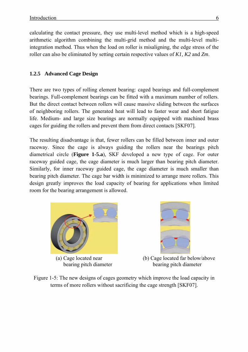
1.2.5 Advanced Cage Design There are two types of rolling element bearing: caged bearings and full-complement bearings. Full-complement bearings can be fitted with a maximum number of rollers. But the direct contact between rollers will cause massive sliding between the surfaces of neighboring rollers. The generated heat will lead to faster wear and short fatigue life. Medium- and large size bearings are normally equipped with machined brass cages for guiding the rollers and prevent them from direct contacts [SKF07]. The resulting disadvantage is that, fewer rollers can be filled between inner and outer raceway. Since the cage is always guiding the rollers near the bearings pitch diametrical circle (Figure 1-5.a), SKF developed a new type of cage. For outer raceway guided cage, the cage diameter is much larger than bearing pitch diameter. Similarly, for inner raceway guided cage, the cage diameter is much smaller than bearing pitch diameter. The cage bar width is minimized to arrange more rollers. This design greatly improves the load capacity of bearing for applications when limited room for the bearing arrangement is allowed.
(a) Cage located near (b) Cage located far below/above
bearing pitch diameter bearing pitch diameter
Figure 1-5: The new designs of cages geometry which improve the load capacity in terms of more rollers without sacrificing the cage strength [SKF07].
Introduction 7
1.3 State-of-the-art of Multi-Body-Simulation
1.3.1 Introduction to Multi-Body-Simulation Multi-body-simulation technology is aimed to investigate the dynamic behavior of interconnected bodies. The interactive forces, time-varying states of each body and contact detection between multi-dimensional surfaces are derived either from ordinary differential equations or partial differential equations.
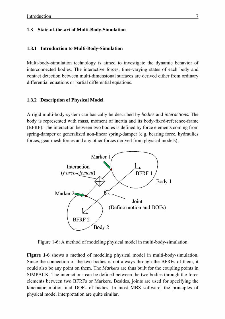
1.3.2 Description of Physical Model A rigid multi-body-system can basically be described by bodies and interactions. The body is represented with mass, moment of inertia and its body-fixed-reference-frame (BFRF). The interaction between two bodies is defined by force elements coming from spring-damper or generalized non-linear spring-damper (e.g. bearing force, hydraulics forces, gear mesh forces and any other forces derived from physical models).
Figure 1-6: A method of modeling physical model in multi-body-simulation Figure 1-6 shows a method of modeling physical model in multi-body-simulation. Since the connection of the two bodies is not always through the BFRFs of them, it could also be any point on them. The Markers are thus built for the coupling points in SIMPACK. The interactions can be defined between the two bodies through the force elements between two BFRFs or Markers. Besides, joints are used for specifying the kinematic motion and DOFs of bodies. In most MBS software, the principles of physical model interpretation are quite similar.
Introduction 8
Furthermore, the bodies mentioned here are not restricted to rigid bodies. Elastic bodies can also be integrated which uses the advantages of FEA and enables us therefore to know both macro and micro behavior of mechanical system. The time-varying dynamic behaviors which are normally in terms of translational velocities, rotational speeds and contact forces can meanwhile result in the structural and local deformation of bodies. This is significant for modern mechanical design and optimization since a deeper insight of dynamic behaviors of bodies is possible in addition to the improvement of material strength and heat treatment.
1.3.3 Equations of Motion After the definition of the interaction of two bodies, the next step is to define the motion of the bodies under given state vectors including position, translational and angular velocity, translational and angular acceleration of bodies. In classical mechanics, the Newton-Euler equations are employed to describe the combined translational and rotational movement of rigid bodies which is given in Equation 1.1[Wik13] [Gin08]:
⎟⎟⎠
⎞⎜⎜⎝
⎛⋅×⋅×
+⎟⎟⎠
⎞⎜⎜⎝
⎛⋅⎟⎟⎠
⎞⎜⎜⎝
⎛=⎟⎟
⎠
⎞⎜⎜⎝
⎛υωυω
α Ima
Im
TF
00
(1.1)
Where: F and T are the total forces and torques acting on the center of mass of the body. m is the mass of the body. υ , a and α are the translational velocity, acceleration and angular acceleration of the center of mass of the body. ω is the rotational velocity of the body. I is the moment of inertia matrix of the body.
In each time-step during simulation the ordinary differential equations will be solved and return the new state variables of the body under certain tolerances. In order to obtain acceptable results, the solver needs to be fast enough and numerically stable.
1.3.4 Commercial MBS Programs To enable us to simulate the behaviors of multi-body-system, commercial multi-body-simulation software experiences a great development in the past 30 year. MSC.ADAMS and SIMPACK AG are the two representative suppliers in this area. They have different efficiency of solving the ordinary equations but in other aspects in terms of modeling, general force-element library, post-processing and interface to CAD and CAE are more or less similar. Other programs such as DADS, Dymola and Virtual.Lab are also competitive. For mechanical engineers who are always emphasizing on the concerned physical effects of the studied system as long as it could be simulated in an acceptable time, the software selection is not a critical issue. It is
Introduction 9
either subject to the economic reasons or personal preferences. In this paper SIMPACK is chosen as platform for the development of cylindrical bearing simulation since many research projects were achieved through SIMPACK in IME.
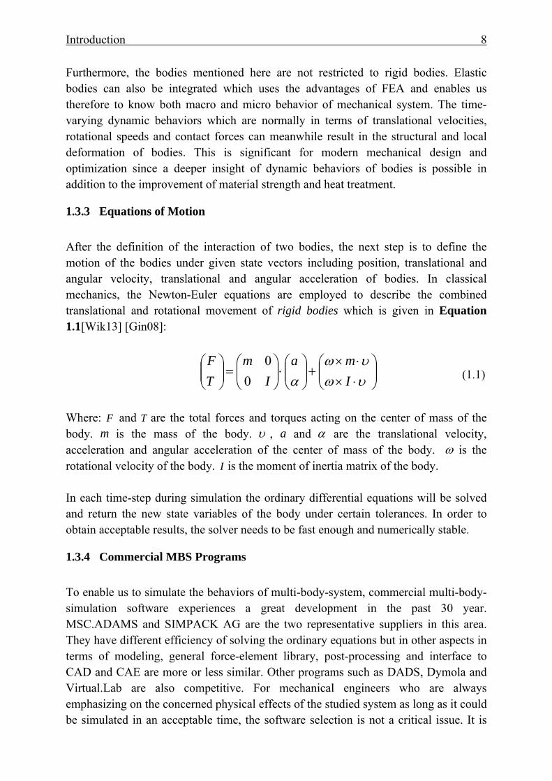
1.3.5 Application of Multi-Body-Simulation Figure 1-7 shows an interpretation of a wind turbine which integrates almost all the physical model such as stochastic wind speed, gearbox, generator, the nacelle and tower. Even if it is not well addressed in each contact such as the bearing forces, it still provides us a systematic insight of the whole mechanical system [Ber11]. The next task of it should be the improvement of important contacts such as main bearing non-linear stiffness calculation, bearing behavior in transient loading cases, 3D model of gear mesh and the flexibilities of the blades, nacelle and tower.
Figure 1-7: Multi-body-simulation of a wind turbine in SIMPACK [Ber11]
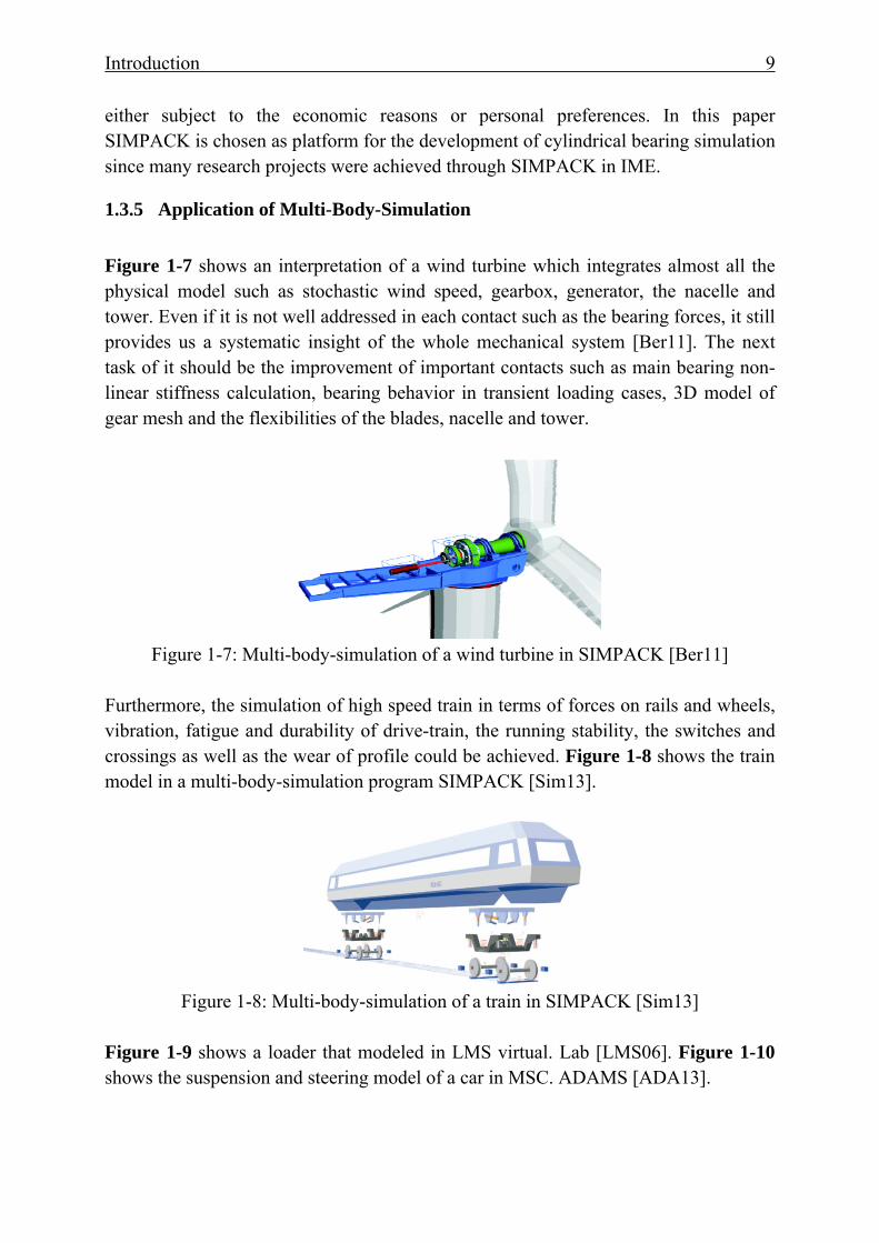
Furthermore, the simulation of high speed train in terms of forces on rails and wheels, vibration, fatigue and durability of drive-train, the running stability, the switches and crossings as well as the wear of profile could be achieved. Figure 1-8 shows the train model in a multi-body-simulation program SIMPACK [Sim13].
Figure 1-8: Multi-body-simulation of a train in SIMPACK [Sim13]
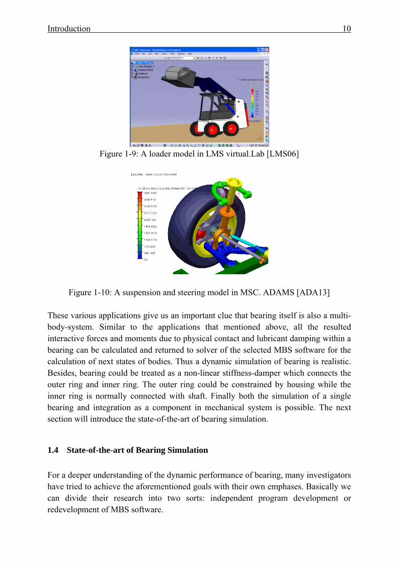
Figure 1-9 shows a loader that modeled in LMS virtual. Lab [LMS06]. Figure 1-10 shows the suspension and steering model of a car in MSC. ADAMS [ADA13].
Introduction 10
Figure 1-9: A loader model in LMS virtual.Lab [LMS06]
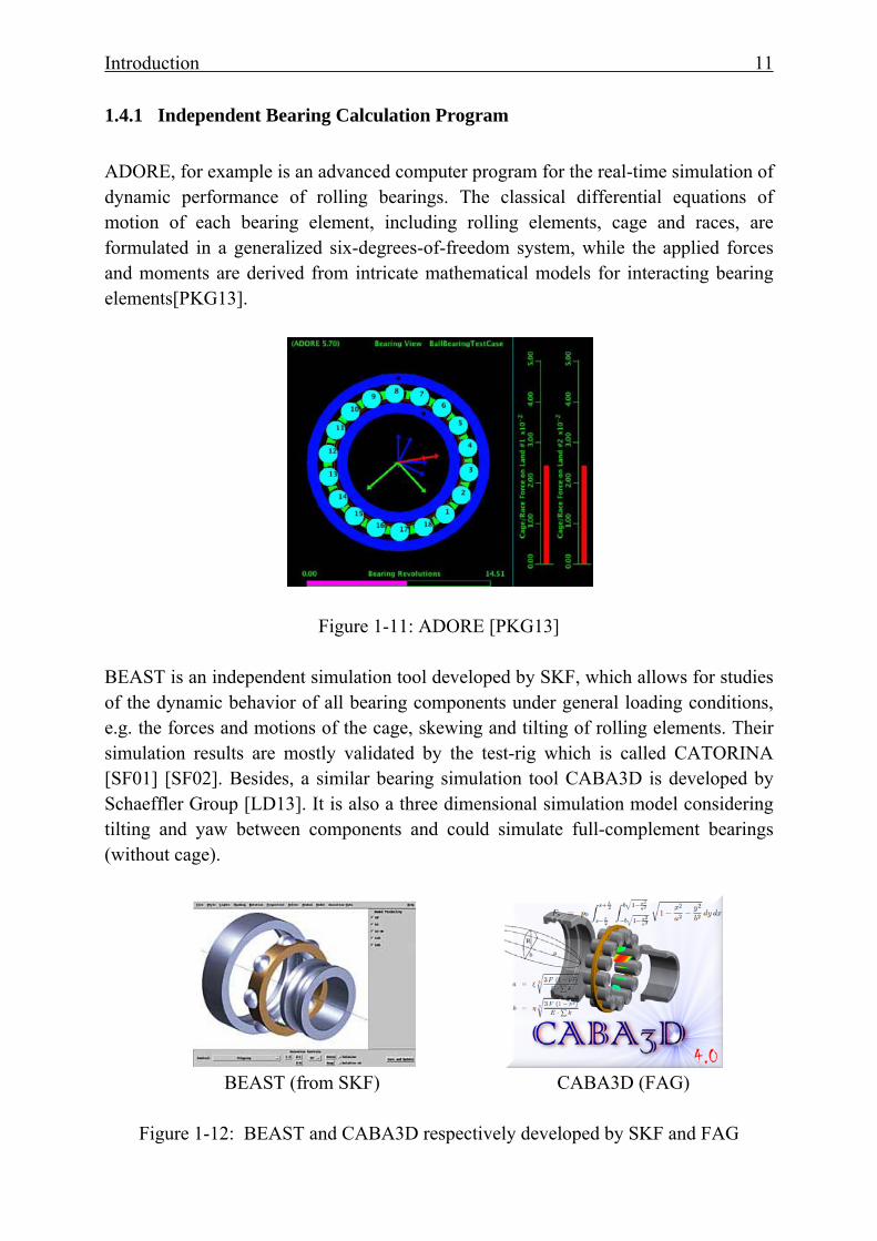
Figure 1-10: A suspension and steering model in MSC. ADAMS [ADA13]
These various applications give us an important clue that bearing itself is also a multi-body-system. Similar to the applications that mentioned above, all the resulted interactive forces and moments due to physical contact and lubricant damping within a bearing can be calculated and returned to solver of the selected MBS software for the calculation of next states of bodies. Thus a dynamic simulation of bearing is realistic. Besides, bearing could be treated as a non-linear stiffness-damper which connects the outer ring and inner ring. The outer ring could be constrained by housing while the inner ring is normally connected with shaft. Finally both the simulation of a single bearing and integration as a component in mechanical system is possible. The next section will introduce the state-of-the-art of bearing simulation.
1.4 State-of-the-art of Bearing Simulation For a deeper understanding of the dynamic performance of bearing, many investigators have tried to achieve the aforementioned goals with their own emphases. Basically we can divide their research into two sorts: independent program development or redevelopment of MBS software.
Introduction 11
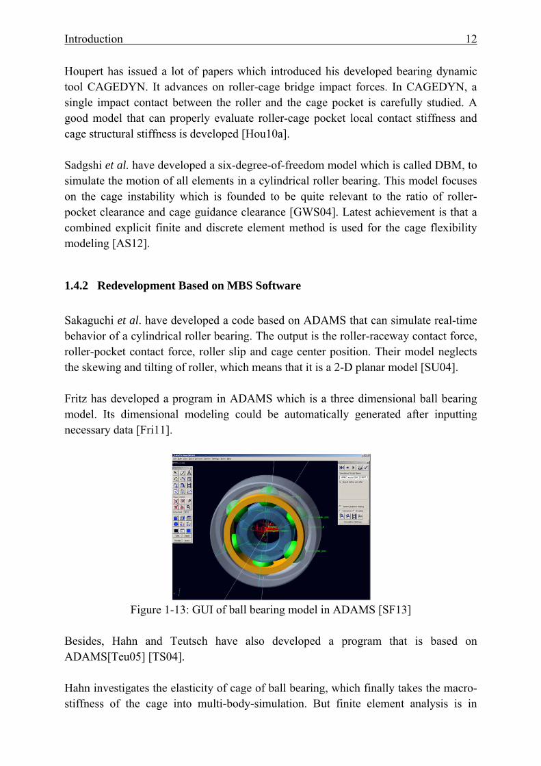
1.4.1 Independent Bearing Calculation Program ADORE, for example is an advanced computer program for the real-time simulation of dynamic performance of rolling bearings. The classical differential equations of motion of each bearing element, including rolling elements, cage and races, are formulated in a generalized six-degrees-of-freedom system, while the applied forces and moments are derived from intricate mathematical models for interacting bearing elements[PKG13].
Figure 1-11: ADORE [PKG13]
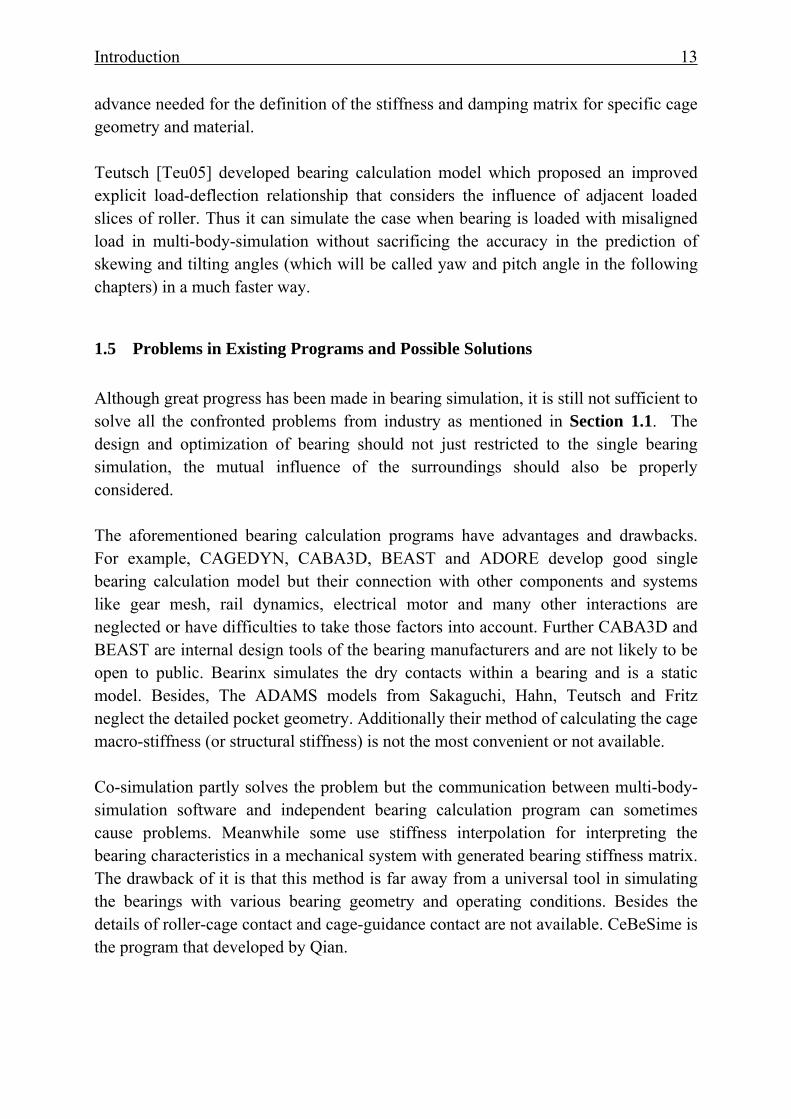
BEAST is an independent simulation tool developed by SKF, which allows for studies of the dynamic behavior of all bearing components under general loading conditions, e.g. the forces and motions of the cage, skewing and tilting of rolling elements. Their simulation results are mostly validated by the test-rig which is called CATORINA [SF01] [SF02]. Besides, a similar bearing simulation tool CABA3D is developed by Schaeffler Group [LD13]. It is also a three dimensional simulation model considering tilting and yaw between components and could simulate full-complement bearings (without cage).
BEAST (from SKF) CABA3D (FAG)
Figure 1-12: BEAST and CABA3D respectively developed by SKF and FAG
Introduction 12
Houpert has issued a lot of papers which introduced his developed bearing dynamic tool CAGEDYN. It advances on roller-cage bridge impact forces. In CAGEDYN, a single impact contact between the roller and the cage pocket is carefully studied. A good model that can properly evaluate roller-cage pocket local contact stiffness and cage structural stiffness is developed [Hou10a]. Sadgshi et al. have developed a six-degree-of-freedom model which is called DBM, to simulate the motion of all elements in a cylindrical roller bearing. This model focuses on the cage instability which is founded to be quite relevant to the ratio of roller-pocket clearance and cage guidance clearance [GWS04]. Latest achievement is that a combined explicit finite and discrete element method is used for the cage flexibility modeling [AS12].
1.4.2 Redevelopment Based on MBS Software Sakaguchi et al. have developed a code based on ADAMS that can simulate real-time behavior of a cylindrical roller bearing. The output is the roller-raceway contact force, roller-pocket contact force, roller slip and cage center position. Their model neglects the skewing and tilting of roller, which means that it is a 2-D planar model [SU04]. Fritz has developed a program in ADAMS which is a three dimensional ball bearing model. Its dimensional modeling could be automatically generated after inputting necessary data [Fri11].
Figure 1-13: GUI of ball bearing model in ADAMS [SF13]
Besides, Hahn and Teutsch have also developed a program that is based on ADAMS[Teu05] [TS04]. Hahn investigates the elasticity of cage of ball bearing, which finally takes the macro-stiffness of the cage into multi-body-simulation. But finite element analysis is in
Introduction 13
advance needed for the definition of the stiffness and damping matrix for specific cage geometry and material. Teutsch [Teu05] developed bearing calculation model which proposed an improved explicit load-deflection relationship that considers the influence of adjacent loaded slices of roller. Thus it can simulate the case when bearing is loaded with misaligned load in multi-body-simulation without sacrificing the accuracy in the prediction of skewing and tilting angles (which will be called yaw and pitch angle in the following chapters) in a much faster way.
1.5 Problems in Existing Programs and Possible Solutions Although great progress has been made in bearing simulation, it is still not sufficient to solve all the confronted problems from industry as mentioned in Section 1.1. The design and optimization of bearing should not just restricted to the single bearing simulation, the mutual influence of the surroundings should also be properly considered.
The aforementioned bearing calculation programs have advantages and drawbacks. For example, CAGEDYN, CABA3D, BEAST and ADORE develop good single bearing calculation model but their connection with other components and systems like gear mesh, rail dynamics, electrical motor and many other interactions are neglected or have difficulties to take those factors into account. Further CABA3D and BEAST are internal design tools of the bearing manufacturers and are not likely to be open to public. Bearinx simulates the dry contacts within a bearing and is a static model. Besides, The ADAMS models from Sakaguchi, Hahn, Teutsch and Fritz neglect the detailed pocket geometry. Additionally their method of calculating the cage macro-stiffness (or structural stiffness) is not the most convenient or not available. Co-simulation partly solves the problem but the communication between multi-body-simulation software and independent bearing calculation program can sometimes cause problems. Meanwhile some use stiffness interpolation for interpreting the bearing characteristics in a mechanical system with generated bearing stiffness matrix. The drawback of it is that this method is far away from a universal tool in simulating the bearings with various bearing geometry and operating conditions. Besides the details of roller-cage contact and cage-guidance contact are not available. CeBeSime is the program that developed by Qian.
Introduction 14
Key Features
Existing Bearing Calculation Model CyBeSime Bearinx CABA-
3D BEAST CAGE-
DYN DBM ADORE Model in
ADAMS*
Slice model ● ● ● ● ● ● ● ● AST ◘ ◘ ◘ ◘ ○ ○ ● ● lubricant damping
○ ● ● ● ● ● ● ●
Pocket stiffness
◘ ● ● ● ● ◘ ○ ●
Cage macro- stiffness
◘ ● ● ● ● ◘ ● ●
Pocket geometry
○ ◘ ◘ ○ ○ ○ ◘ ●
Cage guidance
◘ ◘ ◘ ◘ ● ◘ ● ●
Hysteresis damping
● ● ● ◘ ◘ ○ ◘ ●
3D model? ● ● ● ◘ ◘ ● ● ● Flexibility to mechanical systems
◘
◘
◘
○
○
○ ● ●
● Yes ○ No ◘ Suspected/unknown * Model from Teutsch Table 1-1: Feature comparison on the existing bearing simulation models
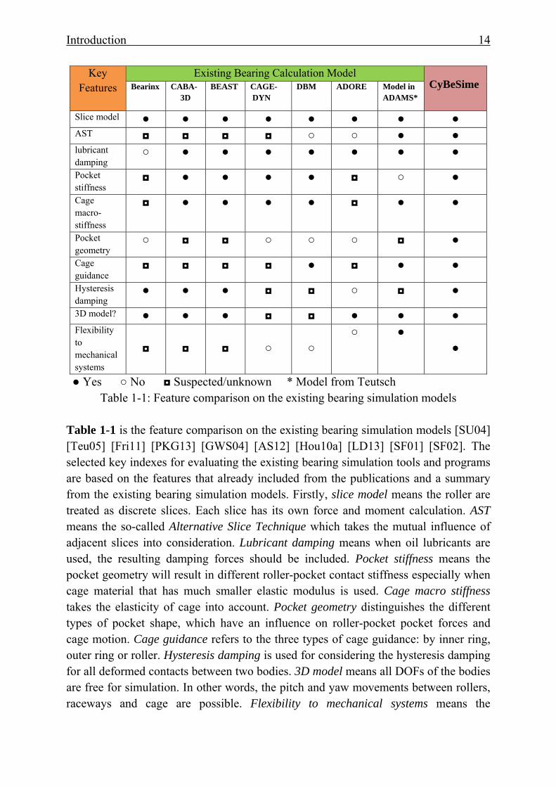
Table 1-1 is the feature comparison on the existing bearing simulation models [SU04] [Teu05] [Fri11] [PKG13] [GWS04] [AS12] [Hou10a] [LD13] [SF01] [SF02]. The selected key indexes for evaluating the existing bearing simulation tools and programs are based on the features that already included from the publications and a summary from the existing bearing simulation models. Firstly, slice model means the roller are treated as discrete slices. Each slice has its own force and moment calculation. AST means the so-called Alternative Slice Technique which takes the mutual influence of adjacent slices into consideration. Lubricant damping means when oil lubricants are used, the resulting damping forces should be included. Pocket stiffness means the pocket geometry will result in different roller-pocket contact stiffness especially when cage material that has much smaller elastic modulus is used. Cage macro stiffness takes the elasticity of cage into account. Pocket geometry distinguishes the different types of pocket shape, which have an influence on roller-pocket pocket forces and cage motion. Cage guidance refers to the three types of cage guidance: by inner ring, outer ring or roller. Hysteresis damping is used for considering the hysteresis damping for all deformed contacts between two bodies. 3D model means all DOFs of the bodies are free for simulation. In other words, the pitch and yaw movements between rollers, raceways and cage are possible. Flexibility to mechanical systems means the
Introduction 15
developed bearing simulation tools or programs are flexible to be integrated to other mechanical systems for simulation. In order to avoid all the drawbacks of existing bearing simulation models, a universal bearing model which could properly define the interactions between internal components, and meanwhile the bearing model could be integrated as an element in the simulation of a more complex mechanical system needs to be developed. SIMPACK’s user routine is chosen for the development of describing the kinematics and dynamics of bearing. The detailed bearing behavior could be investigated with variations in terms of shaft speed, radial load, different cage guidance, pocket geometry and lubricant conditions. The high flexibility in modeling bodies and fast solver in commercial multi-body-simulation software keep the engineers away from programming the stable solver themselves. Thus more emphasis can be placed on the modeling and interpretations of bearing interactive contacts into multi-body-simulation.
1.6 Research Objectives A complete three-dimensional bearing simulation program is expected to be developed based on SIMPACK user-routine and with the help of Abaqus. The final destination is to investigate the dynamic performance of cylindrical roller bearing. Firstly, the expected bearing calculation program should have the following basic functionalities:
(1) Define contact stiffness within bearing components such as roller-raceway contact, roller-pocket contact, and roller-rib contact. They should be properly addressed in order to obtain realistic contact forces.
(2) Determine friction coefficient for each contact in each time step during the
simulation, since the traction forces greatly influence roller and cage slippage in load-zone. So the lubricating gap height has to be calculated to separate rigid body friction from fluid friction.
(3) Consider the damping characteristics that could correctly reflect the
dynamical effects or tendency when excitation exists. Damping between roller-raceway, roller-pocket as well as the lubricant squeeze effect between cage and guiding surface should be considered.
(4) Distinguish the different cage guidance because in most cases, cage wear
and vibration will occur due to improper cage guidance type and cage guidance clearance.
Introduction 16
(5) Consider material hysteresis damping in all contacts where deformations exist.
(6) Consider pitch and yaw movement between roller and raceway through
Alternative Slice Technique since misalignment of the load is quite common in many operational conditions. This is also called 3D bearing model.
Following advanced functionalities which have been created by my own research work are added to the program:
(7) Consideration of cage pocket geometry for roller guided cage, inner ring and outer ring guided cage. Simplified method to consider the structural stiffness of the cage by use of reduced FE model and import to SIMPACK.
(8) Flexibility of the simulation program to be integrated to the simulation of
extended mechanical system environment which includes for example shafts, gears and even the presence of generators. In other words, it should not only serve as a single bearing simulation, but allow easy integration into a simulation of a complex system.
(9) Furthermore, it shall return the calculated forces and moments that resulted from the roller-cage pocket contact, to FE analysis for checking the strength of pocket-bridge and side bar. This closed-loop of design chain will finally contribute to the cage wear and fatigue life, when other parameters such as materials and bore diameters are relatively not likely to be adjusted.
Fundamentals of Cylindrical Roller Bearings 17
2 Fundamentals of Cylindrical Roller Bearings
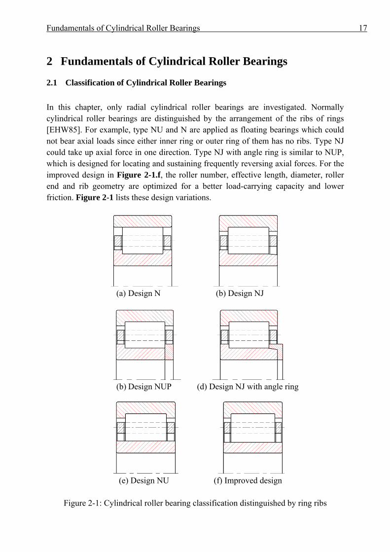
2.1 Classification of Cylindrical Roller Bearings In this chapter, only radial cylindrical roller bearings are investigated. Normally cylindrical roller bearings are distinguished by the arrangement of the ribs of rings [EHW85]. For example, type NU and N are applied as floating bearings which could not bear axial loads since either inner ring or outer ring of them has no ribs. Type NJ could take up axial force in one direction. Type NJ with angle ring is similar to NUP, which is designed for locating and sustaining frequently reversing axial forces. For the improved design in Figure 2-1.f, the roller number, effective length, diameter, roller end and rib geometry are optimized for a better load-carrying capacity and lower friction. Figure 2-1 lists these design variations.
(a) Design N (b) Design NJ
(b) Design NUP (d) Design NJ with angle ring
(e) Design NU (f) Improved design
Figure 2-1: Cylindrical roller bearing classification distinguished by ring ribs
Fundamentals of Cylindrical Roller Bearings 18
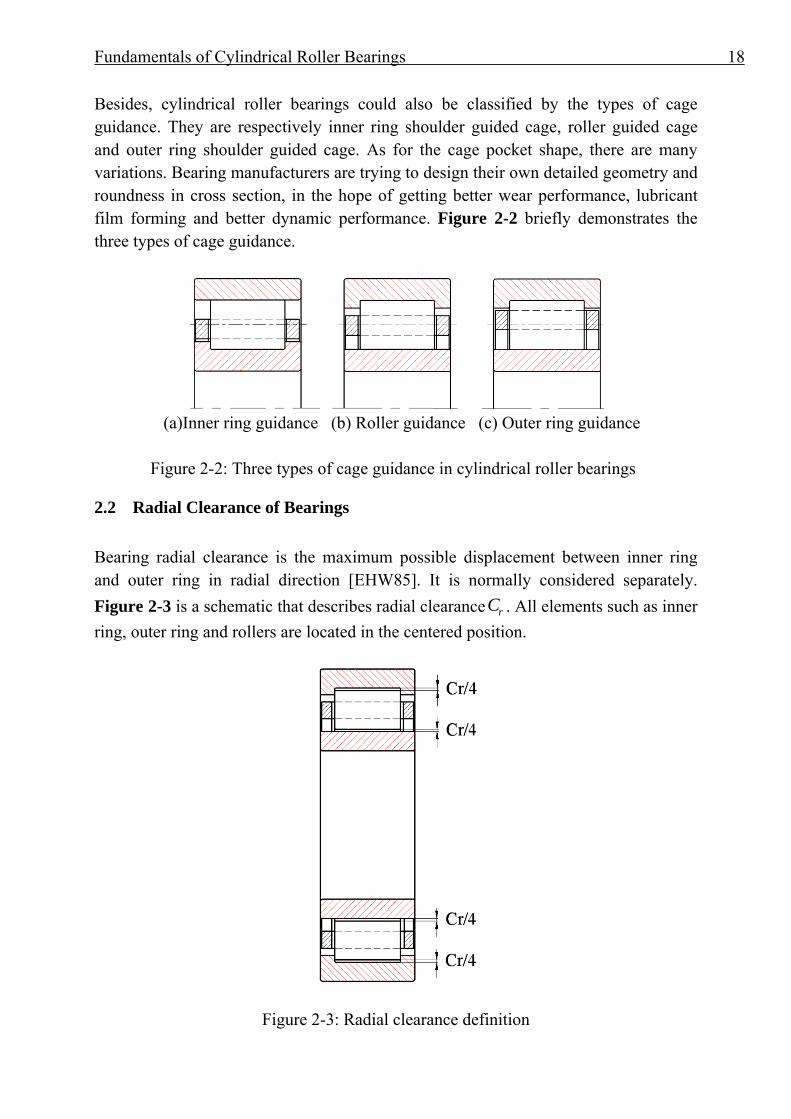
Besides, cylindrical roller bearings could also be classified by the types of cage guidance. They are respectively inner ring shoulder guided cage, roller guided cage and outer ring shoulder guided cage. As for the cage pocket shape, there are many variations. Bearing manufacturers are trying to design their own detailed geometry and roundness in cross section, in the hope of getting better wear performance, lubricant film forming and better dynamic performance. Figure 2-2 briefly demonstrates the three types of cage guidance.
(a)Inner ring guidance (b) Roller guidance (c) Outer ring guidance Figure 2-2: Three types of cage guidance in cylindrical roller bearings
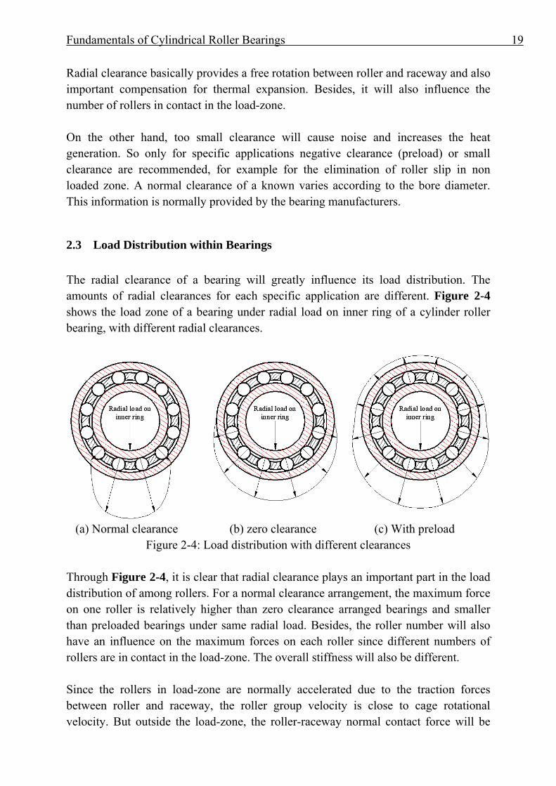
2.2 Radial Clearance of Bearings Bearing radial clearance is the maximum possible displacement between inner ring and outer ring in radial direction [EHW85]. It is normally considered separately. Figure 2-3 is a schematic that describes radial clearance rC . All elements such as inner ring, outer ring and rollers are located in the centered position.
Figure 2-3: Radial clearance definition
Fundamentals of Cylindrical Roller Bearings 19
Radial clearance basically provides a free rotation between roller and raceway and also important compensation for thermal expansion. Besides, it will also influence the number of rollers in contact in the load-zone. On the other hand, too small clearance will cause noise and increases the heat generation. So only for specific applications negative clearance (preload) or small clearance are recommended, for example for the elimination of roller slip in non loaded zone. A normal clearance of a known varies according to the bore diameter. This information is normally provided by the bearing manufacturers.
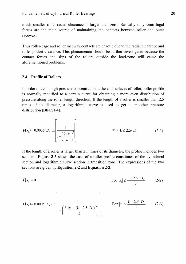
2.3 Load Distribution within Bearings The radial clearance of a bearing will greatly influence its load distribution. The amounts of radial clearances for each specific application are different. Figure 2-4 shows the load zone of a bearing under radial load on inner ring of a cylinder roller bearing, with different radial clearances.
(a) Normal clearance (b) zero clearance (c) With preload
Figure 2-4: Load distribution with different clearances Through Figure 2-4, it is clear that radial clearance plays an important part in the load distribution of among rollers. For a normal clearance arrangement, the maximum force on one roller is relatively higher than zero clearance arranged bearings and smaller than preloaded bearings under same radial load. Besides, the roller number will also have an influence on the maximum forces on each roller since different numbers of rollers are in contact in the load-zone. The overall stiffness will also be different. Since the rollers in load-zone are normally accelerated due to the traction forces between roller and raceway, the roller group velocity is close to cage rotational velocity. But outside the load-zone, the roller-raceway normal contact force will be
Fundamentals of Cylindrical Roller Bearings 20
much smaller if its radial clearance is larger than zero. Basically only centrifugal forces are the main source of maintaining the contacts between roller and outer raceway. Thus roller-cage and roller raceway contacts are chaotic due to the radial clearance and roller-pocket clearance. This phenomenon should be further investigated because the contact forces and slips of the rollers outside the load-zone will cause the aforementioned problems.
2.4 Profile of Rollers In order to avoid high pressure concentration at the end surfaces of roller, roller profile is normally modified to a certain curve for obtaining a more even distribution of pressure along the roller length direction. If the length of a roller is smaller than 2.5 times of its diameter, a logarithmic curve is used to get a smoother pressure distribution [DIN281-4]:
( )⎥⎥⎥⎥
⎦
⎤
⎢⎢⎢⎢
⎣
⎡
⎟⎠⎞
⎜⎝⎛ ⋅
−
⋅⋅= 221
1ln0035.0
Lx
DxPi
ri For rDL ⋅≤ 5.2 (2-1)
If the length of a roller is larger than 2.5 times of its diameter, the profile includes two sections. Figure 2-5 shows the case of a roller profile constitutes of the cylindrical section and logarithmic curve section in transition zone. The expressions of the two sections are given by Equation 2-2 and Equation 2-3.
( ) 0=ixP For 25.2 r
iDLx ⋅−
≤ (2-2)
( )
⎥⎥⎥⎥⎥
⎦
⎤
⎢⎢⎢⎢⎢
⎣
⎡
⎟⎟⎠
⎞⎜⎜⎝
⎛ ⋅−−⋅−
⋅⋅= 2)5.2(2
1
1ln0005.0
LDLx
DxPri
ri For 25.2 r
iDLx ⋅−
> (2-3)
Fundamentals of Cylindrical Roller Bearings 21
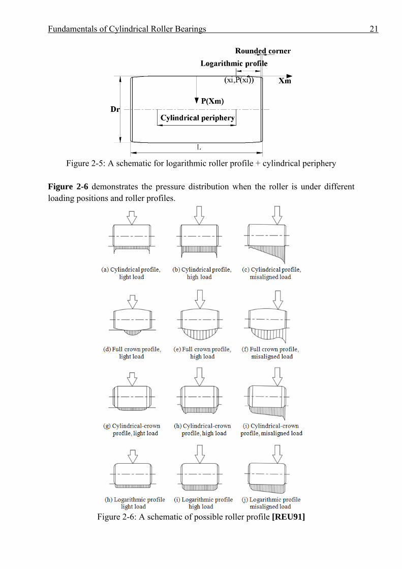
Figure 2-5: A schematic for logarithmic roller profile + cylindrical periphery
Figure 2-6 demonstrates the pressure distribution when the roller is under different loading positions and roller profiles.
Figure 2-6: A schematic of possible roller profile [REU91]
Fundamentals of Cylindrical Roller Bearings 22
We can notice that, those profiled rollers have apparently more even pressure distribution. This feature can greatly decrease the maximum stress in the subsurface and therefore improve the load-carrying capacity and wear performance.
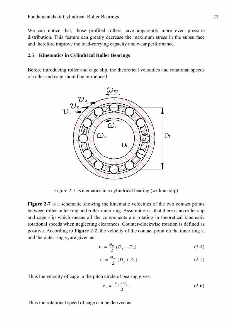
2.5 Kinematics in Cylindrical Roller Bearings Before introducing roller and cage slip, the theoretical velocities and rotational speeds of roller and cage should be introduced.
Figure 2-7: Kinematics in a cylindrical bearing (without slip)
Figure 2-7 is a schematic showing the kinematic velocities of the two contact points between roller-outer ring and roller-inner ring. Assumption is that there is no roller slip and cage slip which means all the components are rotating in theoretical kinematic rotational speeds when neglecting clearances. Counter-clockwise rotation is defined as positive. According to Figure 2-7, the velocity of the contact point on the inner ring vi and the outer ring vo are given as:
)(2 rp
iri DD −=
ων (2-4)
)(2 rpor
o DD +=ων (2-5)
Thus the velocity of cage in the pitch circle of bearing gives:
2
oic
ννν += (2-6)
Thus the rotational speed of cage can be derived as:
Fundamentals of Cylindrical Roller Bearings 23
)1(2
)1(2 p
ror
p
rirc D
DDD
++−=ωωω (2-7)
If only the inner ring or the outer ring rotates, the equation can be reduced to:
)1(2 p
rirc D
D±=
ωω (2-8)
The rotational speed of the roller around it own center gives:
)(2 p
r
r
pirr D
DDD
−±=ωω (2-9)
Where: irω and orω is the rotational speed of inner and outer ring, rD is the roller diameter and pD is the bearing pitch diameter. The minus sign signifies a rotating inner ring and the plus sign means a rotating outer ring. During the rotation of the bearing, both the roller and the cage will unavoidably have a certain slippage towards the rings due to insufficient traction friction outside the load-zone, churning moment from lubricant, the friction loss between roller-pocket contact and roller-rib contacts. The roller slip is defined as: the difference between the actual time-varying rotational velocity raω and the theoretical velocity rω , divided by the theoretical velocity [EHW85]:
%100×−
=r
rarrs
ωωω
(2-10)
Similarly the cage slip ratio cs is defined as:
%100×−
=c
acccs
ωωω
(2-11)
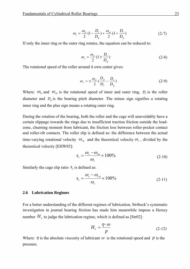
2.6 Lubrication Regimes For a better understanding of the different regimes of lubrication, Stribeck’s systematic investigation in journal bearing friction has made him meanwhile impose a Hersey number sH to judge the lubrication regime, which is defined as [Str02]:
pHs
ωη ⋅= (2-12)
Where: η is the absolute viscosity of lubricant ω is the rotational speed and p is the pressure.
Fundamentals of Cylindrical Roller Bearings 24
Figure 2-8: A Stribeck curve that determines lubrication regimes
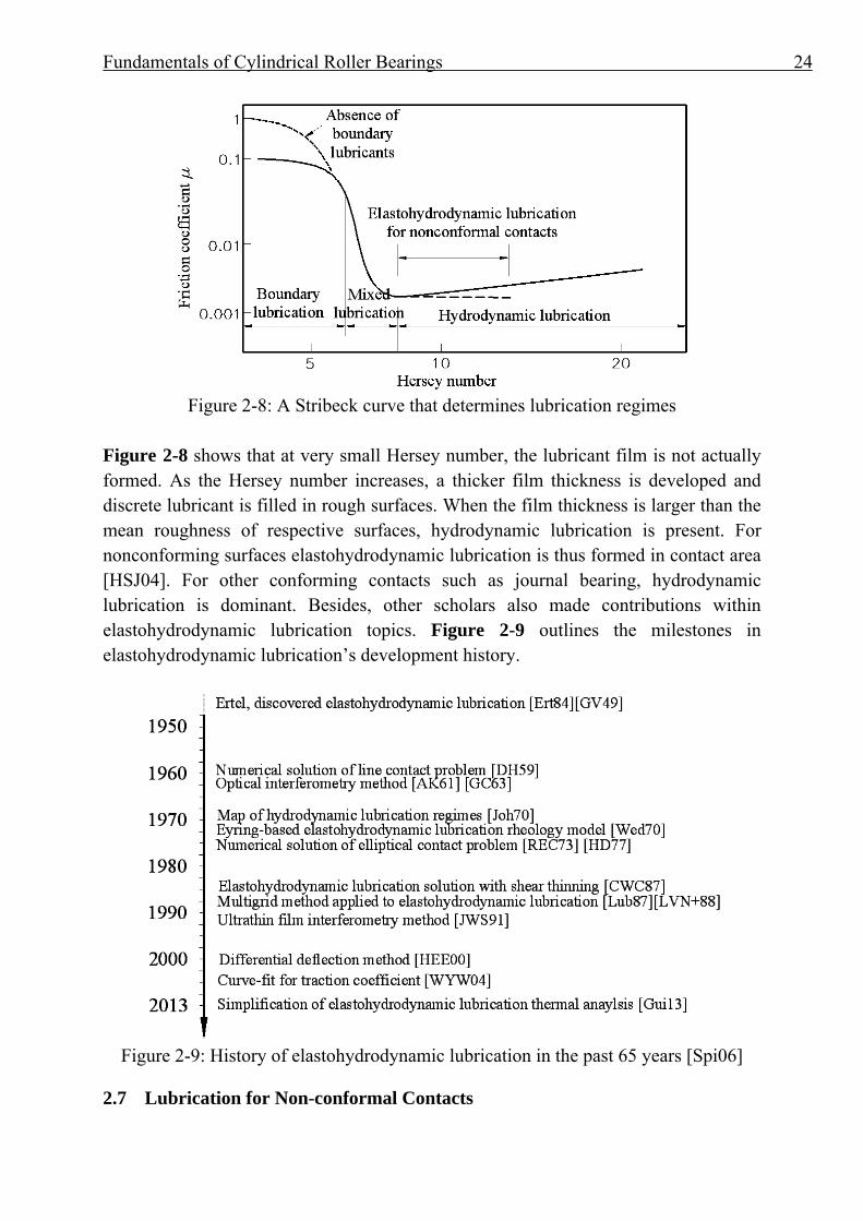
Figure 2-8 shows that at very small Hersey number, the lubricant film is not actually formed. As the Hersey number increases, a thicker film thickness is developed and discrete lubricant is filled in rough surfaces. When the film thickness is larger than the mean roughness of respective surfaces, hydrodynamic lubrication is present. For nonconforming surfaces elastohydrodynamic lubrication is thus formed in contact area [HSJ04]. For other conforming contacts such as journal bearing, hydrodynamic lubrication is dominant. Besides, other scholars also made contributions within elastohydrodynamic lubrication topics. Figure 2-9 outlines the milestones in elastohydrodynamic lubrication’s development history.
Figure 2-9: History of elastohydrodynamic lubrication in the past 65 years [Spi06]
2.7 Lubrication for Non-conformal Contacts
Fundamentals of Cylindrical Roller Bearings 25
Lubricants are widely used to reduce friction and wear between conformal and non-conformal surfaces. Basically the conformal surfaces means there are relatively larger contact areas. For example in journal bearings the radial clearance between bearing and journal is typically one-thousandth of the journal diameter [HSJ04], and the contact area is relatively large. By contrast, in rolling bearings, non-conformal surfaces are presented due to its narrower lubrication area and higher load. When a high load is exerted on a much smaller area, the deformed area is still much smaller than equivalent radius. Gear teeth mating, cams and followers as well as rolling bearings are good examples of non-conformal contacts [HSJ04]. How to decide the corresponding friction coefficient is an important task for the calculation of a bearing. The Bearing will have a different behavior when different lubricant is used since the traction behavior in the load-zone and the forming of elastohydrodynamic lubrication film is subject to the characteristics of lubricant. Besides in non load-zone, the resisting moment due to lubricant and larger amount of lubricant in roller-pocket gap and roller-raceway will make the roller and cage behavior much more complex.
2.8 Determination of Friction Coefficients in Bearing
In multi-body-simulation, based on the same tendency as the Stribeck curve, Hersey number is replaced by the film parameter for identifying the different lubrication regimes since the Stribeck curve may not properly address the switch from hydrodynamic lubrication to elastohydrodynamic lubrication. The film parameter Λ is defined as [HSJ04]:
22raro RR
h+
=Λ (2-13)
Where:
:roR Root mean square surface finish of roller surface
:raR Root mean square surface finish of raceway surface :h Minimum/central film thickness for elastohydrodynamic/non- elastohydrodynamic lubrication
Fundamentals of Cylindrical Roller Bearings 26
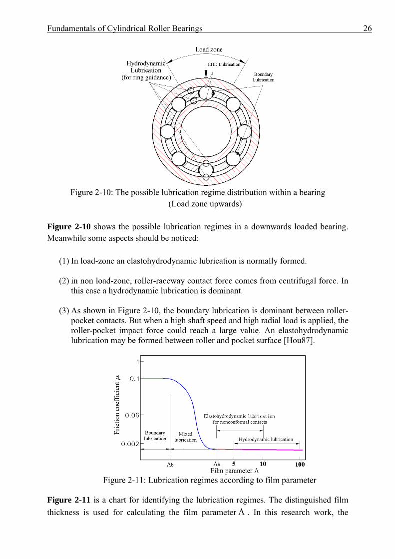
Figure 2-10: The possible lubrication regime distribution within a bearing
(Load zone upwards) Figure 2-10 shows the possible lubrication regimes in a downwards loaded bearing. Meanwhile some aspects should be noticed:
(1) In load-zone an elastohydrodynamic lubrication is normally formed.
(2) in non load-zone, roller-raceway contact force comes from centrifugal force. In this case a hydrodynamic lubrication is dominant.
(3) As shown in Figure 2-10, the boundary lubrication is dominant between roller-pocket contacts. But when a high shaft speed and high radial load is applied, the roller-pocket impact force could reach a large value. An elastohydrodynamic lubrication may be formed between roller and pocket surface [Hou87].
Figure 2-11: Lubrication regimes according to film parameter
Figure 2-11 is a chart for identifying the lubrication regimes. The distinguished film thickness is used for calculating the film parameter Λ . In this research work, the
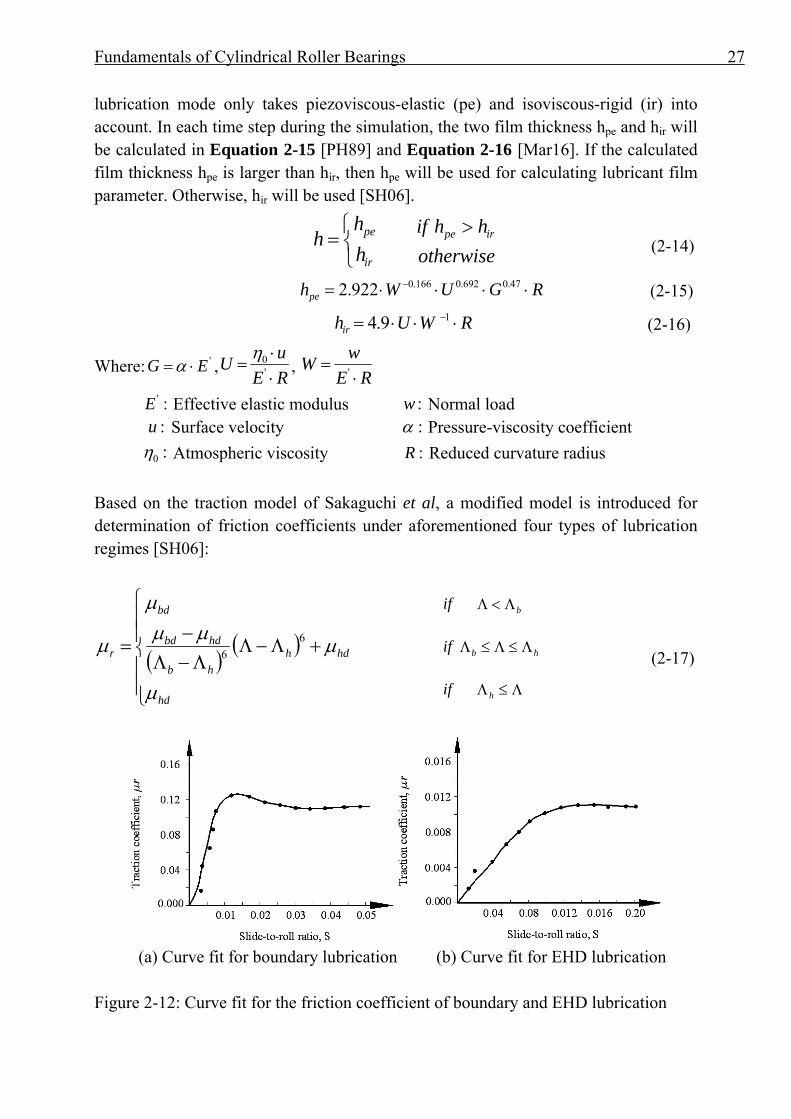
Fundamentals of Cylindrical Roller Bearings 27
lubrication mode only takes piezoviscous-elastic (pe) and isoviscous-rigid (ir) into account. In each time step during the simulation, the two film thickness hpe and hir will be calculated in Equation 2-15 [PH89] and Equation 2-16 [Mar16]. If the calculated film thickness hpe is larger than hir, then hpe will be used for calculating lubricant film parameter. Otherwise, hir will be used [SH06].
⎩⎨⎧
=ir
pe
hh
h otherwisehhif irpe >
(2-14)
RGUWhpe ⋅⋅⋅⋅= − 47.0692.0166.0922.2 (2-15)
RWUhir ⋅⋅⋅= −19.4 (2-16)
Where: 'EG ⋅=α ,REuU⋅⋅
= '0η ,
REwW⋅
= '
:'E Effective elastic modulus :w Normal load :u Surface velocity :α Pressure-viscosity coefficient :0η Atmospheric viscosity :R Reduced curvature radius Based on the traction model of Sakaguchi et al, a modified model is introduced for determination of friction coefficients under aforementioned four types of lubrication regimes [SH06]:
( )( )
⎪⎪⎩
⎪⎪⎨
⎧
+Λ−ΛΛ−Λ−
=
hd
hdhhb
hdbd
bd
r
μ
μμμμ
μ 66
if
if
if
Λ≤Λ
Λ≤Λ≤Λ
Λ<Λ
h
hb
b
(2-17)
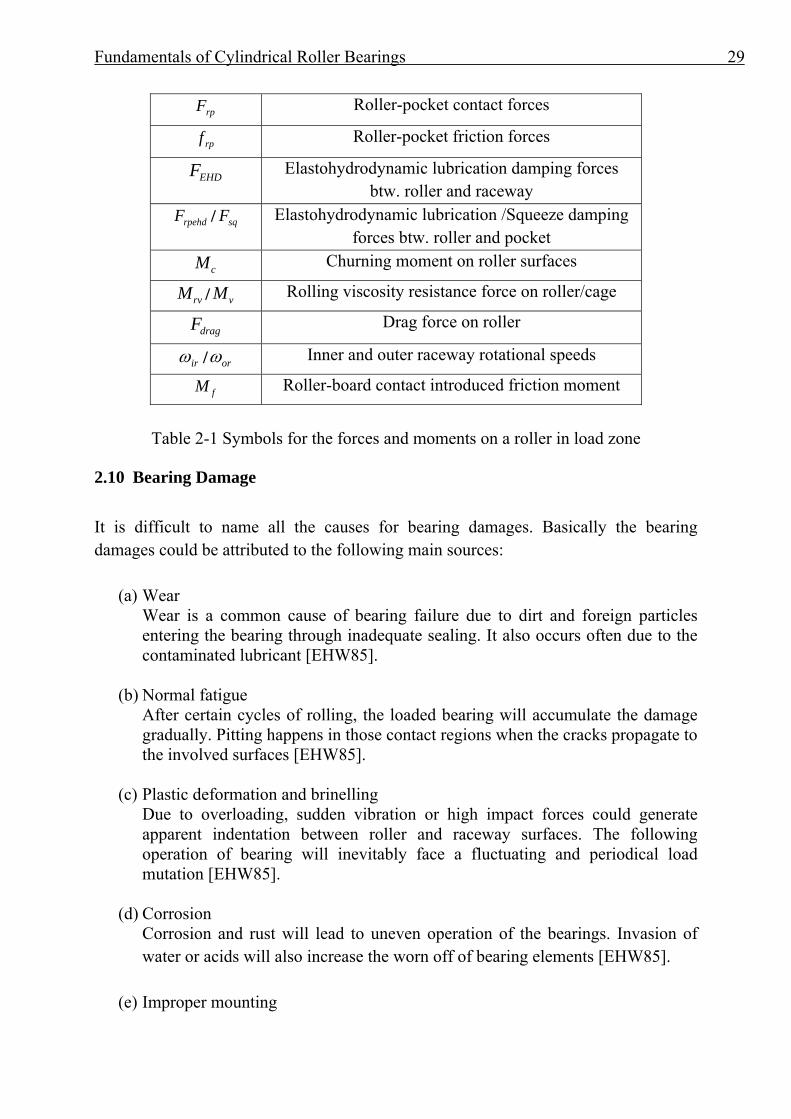
(a) Curve fit for boundary lubrication (b) Curve fit for EHD lubrication
Figure 2-12: Curve fit for the friction coefficient of boundary and EHD lubrication
Fundamentals of Cylindrical Roller Bearings 28
Figure 2-12 shows curve fitting of boundary lubrication and elastohydrodynamic lubrication for selected lubricant and operating temperature. The influence of the normal load on traction coefficient is neglected. Different lubrication regimes are thus identified for each roller at each simulation time step. For a specific bearing, a measurement need to be carried out to get enough data points for curve-fit, which could describe the traction effect much better than empirical equations. If only a tendency analysis is intended, then some empirical values can be used for a quick simulation [SH06].
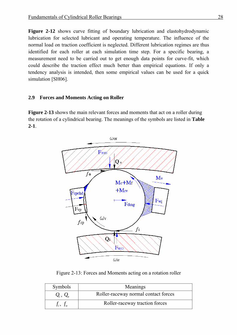
2.9 Forces and Moments Acting on Roller Figure 2-13 shows the main relevant forces and moments that act on a roller during the rotation of a cylindrical bearing. The meanings of the symbols are listed in Table 2-1.
Figure 2-13: Forces and Moments acting on a rotation roller
Symbols Meanings iQ , oQ Roller-raceway normal contact forces
if , of Roller-raceway traction forces
Fundamentals of Cylindrical Roller Bearings 29
rpF Roller-pocket contact forces
rpf Roller-pocket friction forces
EHDF Elastohydrodynamic lubrication damping forces btw. roller and raceway
rpehdF / sqF Elastohydrodynamic lubrication /Squeeze damping forces btw. roller and pocket
cM Churning moment on roller surfaces
rvM / vM Rolling viscosity resistance force on roller/cage
dragF Drag force on roller
irω / orω Inner and outer raceway rotational speeds
fM Roller-board contact introduced friction moment
Table 2-1 Symbols for the forces and moments on a roller in load zone
2.10 Bearing Damage It is difficult to name all the causes for bearing damages. Basically the bearing damages could be attributed to the following main sources:
(a) Wear Wear is a common cause of bearing failure due to dirt and foreign particles entering the bearing through inadequate sealing. It also occurs often due to the contaminated lubricant [EHW85].
(b) Normal fatigue After certain cycles of rolling, the loaded bearing will accumulate the damage gradually. Pitting happens in those contact regions when the cracks propagate to the involved surfaces [EHW85].
(c) Plastic deformation and brinelling Due to overloading, sudden vibration or high impact forces could generate apparent indentation between roller and raceway surfaces. The following operation of bearing will inevitably face a fluctuating and periodical load mutation [EHW85].
(d) Corrosion Corrosion and rust will lead to uneven operation of the bearings. Invasion of water or acids will also increase the worn off of bearing elements [EHW85].
(e) Improper mounting

Fundamentals of Cylindrical Roller Bearings 30
Some bearings need to be preloaded. But preloading may result in nosier running of the bearings. The operational temperature may increase sharply. Excessive radial stressing could be formed.
(f) Smearing under transient load In heavy duty applications, especially when a frequent run-in and braking are happening, the surfaces of the rollers and raceways will have a smearing due to slippage.
2.11 Chapter Summary
In this chapter, the fundamentals of cylindrical roller bearings are introduced. The first aspect is the classification of cylindrical roller bearings in terms of deferent inner ring and outer ring design, or the types of cage guidance. Then the definition of the radial clearance of a cylindrical bearing is explained. Its influence on load distribution in radial plane is also presented. Since it is very common that the cylindrical rollers are crowned, the pressure distributions of different profiles are compared. Regarding the kinematics in cylindrical bearings, the theoretical rotational speed of rollers and the cage are derived assuming no slip during the rotations. The distribution of possible lubrication regimes within a cylindrical bearing are classified according to the lubricant film parameters. Since the traction behavior of the lubricant is quite important for the dynamic performance of cylindrical bearings, the friction coefficient for different lubrication regimes are derived through the curve-fit of obtained data from measurements. Afterwards, a chart that demonstrates of the possible forces and moments acting on a roller is given. Lastly, the main damage modes of cylindrical bearings are explained. These fundamentals enable the engineers to have a good understanding about cylindrical bearings and are useful for finding out the key parameters that are representing a cylindrical bearing model in multi-body- simulations.
Modeling Bearing in SIMPACK 31
3 Modeling Bearing in SIMPACK
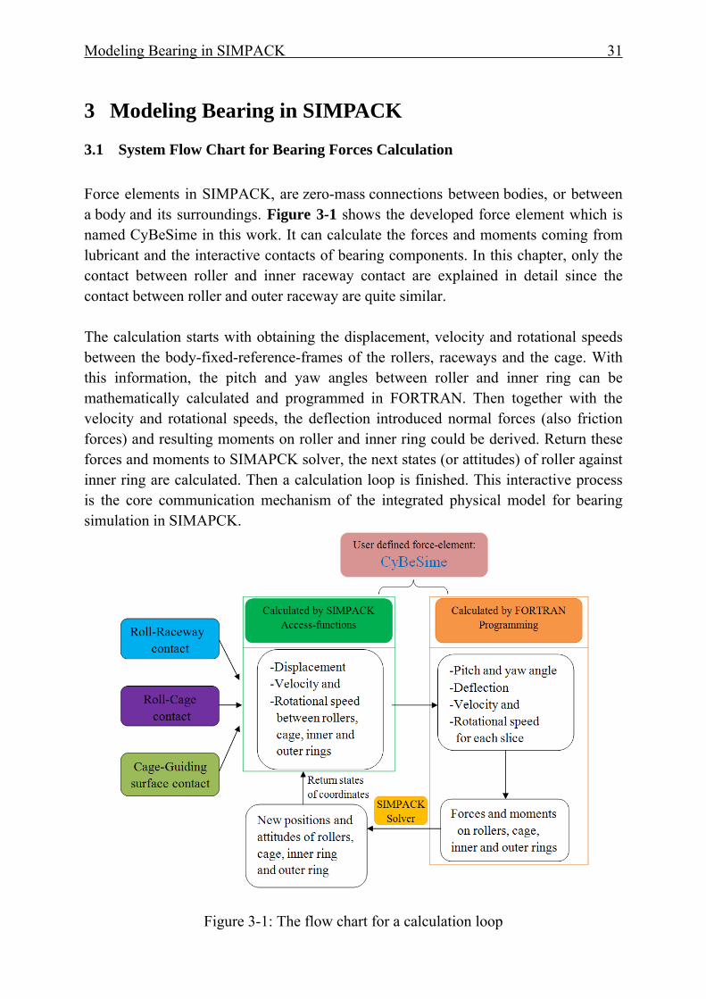
3.1 System Flow Chart for Bearing Forces Calculation Force elements in SIMPACK, are zero-mass connections between bodies, or between a body and its surroundings. Figure 3-1 shows the developed force element which is named CyBeSime in this work. It can calculate the forces and moments coming from lubricant and the interactive contacts of bearing components. In this chapter, only the contact between roller and inner raceway contact are explained in detail since the contact between roller and outer raceway are quite similar. The calculation starts with obtaining the displacement, velocity and rotational speeds between the body-fixed-reference-frames of the rollers, raceways and the cage. With this information, the pitch and yaw angles between roller and inner ring can be mathematically calculated and programmed in FORTRAN. Then together with the velocity and rotational speeds, the deflection introduced normal forces (also friction forces) and resulting moments on roller and inner ring could be derived. Return these forces and moments to SIMAPCK solver, the next states (or attitudes) of roller against inner ring are calculated. Then a calculation loop is finished. This interactive process is the core communication mechanism of the integrated physical model for bearing simulation in SIMAPCK.
Figure 3-1: The flow chart for a calculation loop
Modeling Bearing in SIMPACK 32
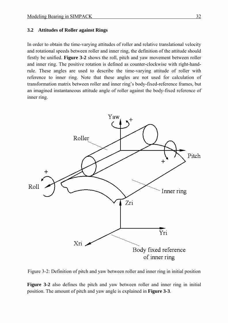
3.2 Attitudes of Roller against Rings In order to obtain the time-varying attitudes of roller and relative translational velocity and rotational speeds between roller and inner ring, the definition of the attitude should firstly be unified. Figure 3-2 shows the roll, pitch and yaw movement between roller and inner ring. The positive rotation is defined as counter-clockwise with right-hand-rule. These angles are used to describe the time-varying attitude of roller with reference to inner ring. Note that these angles are not used for calculation of transformation matrix between roller and inner ring’s body-fixed-reference frames, but an imagined instantaneous attitude angle of roller against the body-fixed reference of inner ring.
Figure 3-2: Definition of pitch and yaw between roller and inner ring in initial position Figure 3-2 also defines the pitch and yaw between roller and inner ring in initial position. The amount of pitch and yaw angle is explained in Figure 3-3.
Modeling Bearing in SIMPACK 33
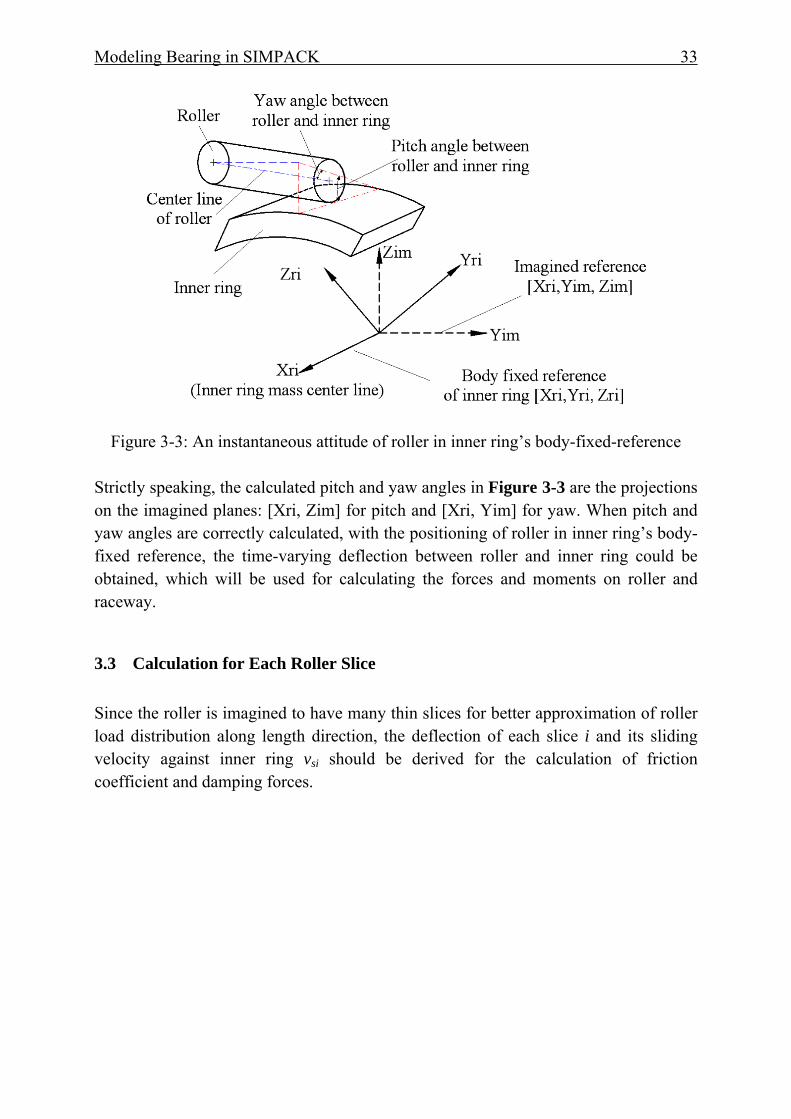
Figure 3-3: An instantaneous attitude of roller in inner ring’s body-fixed-reference
Strictly speaking, the calculated pitch and yaw angles in Figure 3-3 are the projections on the imagined planes: [Xri, Zim] for pitch and [Xri, Yim] for yaw. When pitch and yaw angles are correctly calculated, with the positioning of roller in inner ring’s body-fixed reference, the time-varying deflection between roller and inner ring could be obtained, which will be used for calculating the forces and moments on roller and raceway.
3.3 Calculation for Each Roller Slice Since the roller is imagined to have many thin slices for better approximation of roller load distribution along length direction, the deflection of each slice i and its sliding velocity against inner ring vsi should be derived for the calculation of friction coefficient and damping forces.
Modeling Bearing in SIMPACK 34
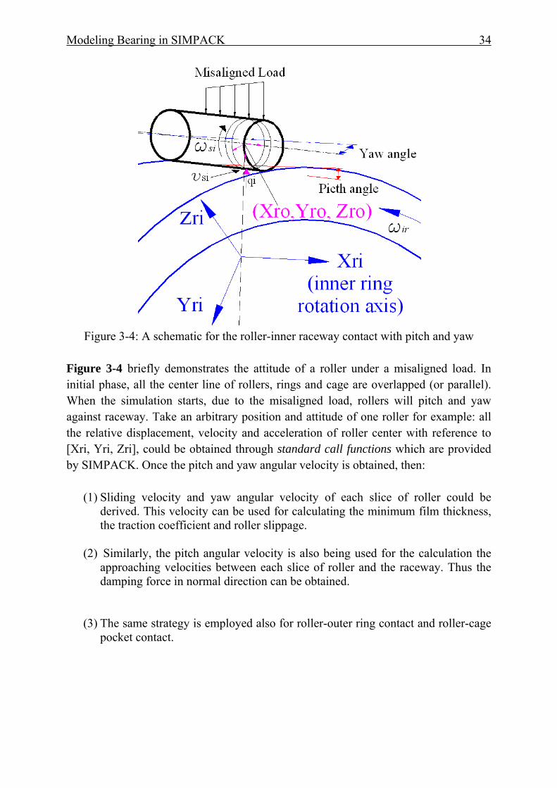
Figure 3-4: A schematic for the roller-inner raceway contact with pitch and yaw
Figure 3-4 briefly demonstrates the attitude of a roller under a misaligned load. In initial phase, all the center line of rollers, rings and cage are overlapped (or parallel). When the simulation starts, due to the misaligned load, rollers will pitch and yaw against raceway. Take an arbitrary position and attitude of one roller for example: all the relative displacement, velocity and acceleration of roller center with reference to [Xri, Yri, Zri], could be obtained through standard call functions which are provided by SIMPACK. Once the pitch and yaw angular velocity is obtained, then:
(1) Sliding velocity and yaw angular velocity of each slice of roller could be derived. This velocity can be used for calculating the minimum film thickness, the traction coefficient and roller slippage.
(2) Similarly, the pitch angular velocity is also being used for the calculation the approaching velocities between each slice of roller and the raceway. Thus the damping force in normal direction can be obtained.
(3) The same strategy is employed also for roller-outer ring contact and roller-cage pocket contact.
Modeling Bearing in SIMPACK 35
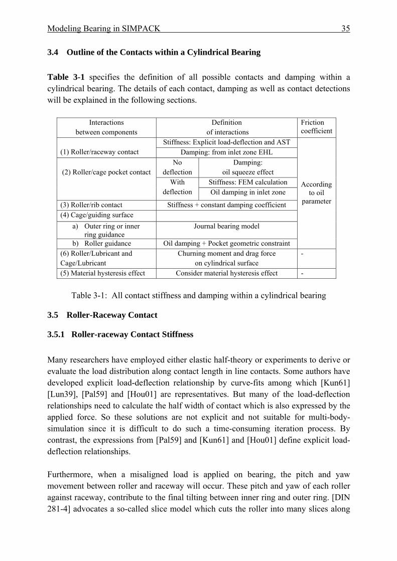
3.4 Outline of the Contacts within a Cylindrical Bearing Table 3-1 specifies the definition of all possible contacts and damping within a cylindrical bearing. The details of each contact, damping as well as contact detections will be explained in the following sections.
Interactions between components
Definition of interactions
Friction coefficient
(1) Roller/raceway contact
Stiffness: Explicit load-deflection and AST
According to oil
parameter
Damping: from inlet zone EHL
(2) Roller/cage pocket contact No
deflection Damping:
oil squeeze effect With
deflection Stiffness: FEM calculation Oil damping in inlet zone
(3) Roller/rib contact Stiffness + constant damping coefficient (4) Cage/guiding surface
a) Outer ring or inner ring guidance
Journal bearing model
b) Roller guidance Oil damping + Pocket geometric constraint (6) Roller/Lubricant and Cage/Lubricant
Churning moment and drag force on cylindrical surface
-
(5) Material hysteresis effect Consider material hysteresis effect -
Table 3-1: All contact stiffness and damping within a cylindrical bearing
3.5 Roller-Raceway Contact
3.5.1 Roller-raceway Contact Stiffness Many researchers have employed either elastic half-theory or experiments to derive or evaluate the load distribution along contact length in line contacts. Some authors have developed explicit load-deflection relationship by curve-fits among which [Kun61] [Lun39], [Pal59] and [Hou01] are representatives. But many of the load-deflection relationships need to calculate the half width of contact which is also expressed by the applied force. So these solutions are not explicit and not suitable for multi-body-simulation since it is difficult to do such a time-consuming iteration process. By contrast, the expressions from [Pal59] and [Kun61] and [Hou01] define explicit load-deflection relationships. Furthermore, when a misaligned load is applied on bearing, the pitch and yaw movement between roller and raceway will occur. These pitch and yaw of each roller against raceway, contribute to the final tilting between inner ring and outer ring. [DIN 281-4] advocates a so-called slice model which cuts the roller into many slices along
Modeling Bearing in SIMPACK 36
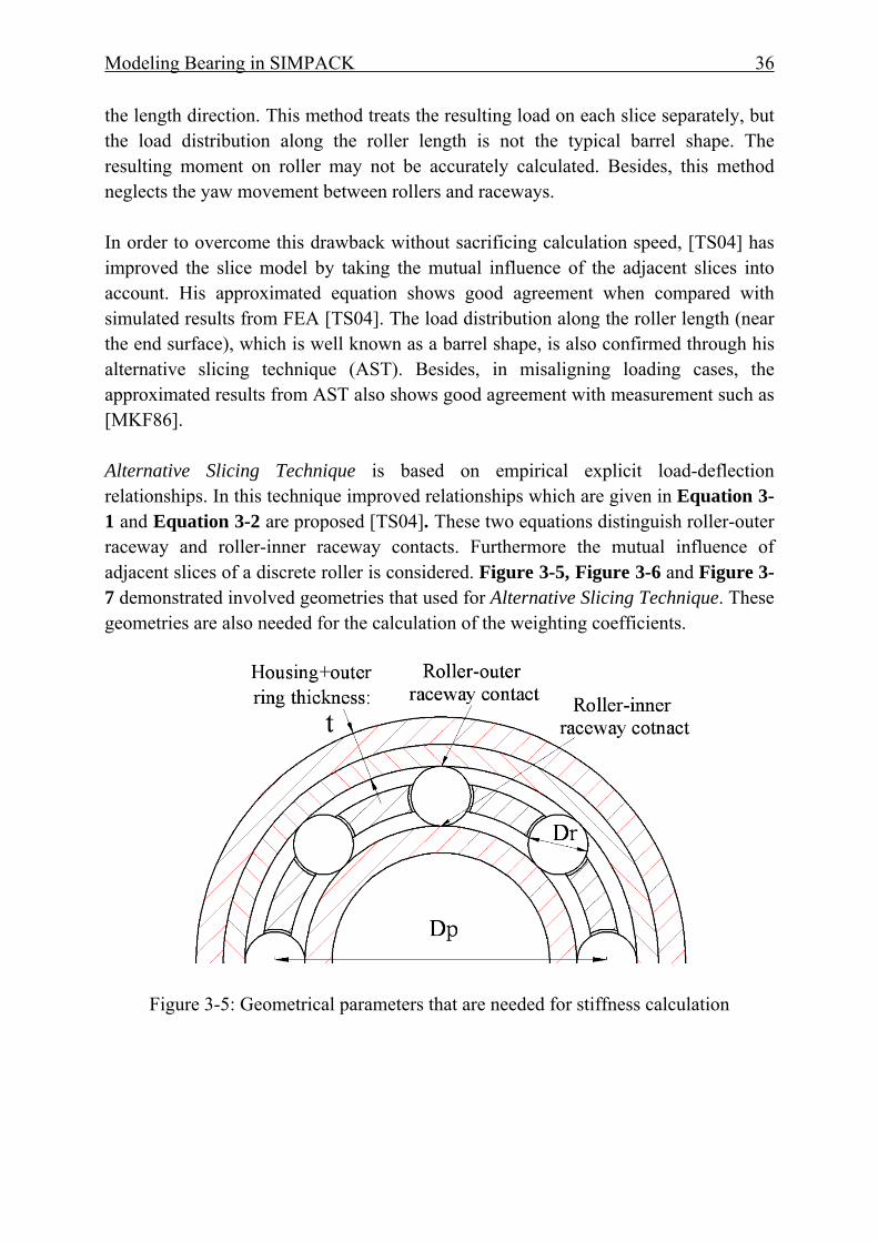
the length direction. This method treats the resulting load on each slice separately, but the load distribution along the roller length is not the typical barrel shape. The resulting moment on roller may not be accurately calculated. Besides, this method neglects the yaw movement between rollers and raceways. In order to overcome this drawback without sacrificing calculation speed, [TS04] has improved the slice model by taking the mutual influence of the adjacent slices into account. His approximated equation shows good agreement when compared with simulated results from FEA [TS04]. The load distribution along the roller length (near the end surface), which is well known as a barrel shape, is also confirmed through his alternative slicing technique (AST). Besides, in misaligning loading cases, the approximated results from AST also shows good agreement with measurement such as [MKF86]. Alternative Slicing Technique is based on empirical explicit load-deflection relationships. In this technique improved relationships which are given in Equation 3-1 and Equation 3-2 are proposed [TS04]. These two equations distinguish roller-outer raceway and roller-inner raceway contacts. Furthermore the mutual influence of adjacent slices of a discrete roller is considered. Figure 3-5, Figure 3-6 and Figure 3-7 demonstrated involved geometries that used for Alternative Slicing Technique. These geometries are also needed for the calculation of the weighting coefficients.
Figure 3-5: Geometrical parameters that are needed for stiffness calculation
Modeling Bearing in SIMPACK 37
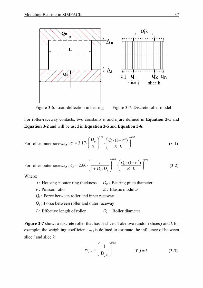
Figure 3-6: Load-deflection in bearing Figure 3-7: Discrete roller model
For roller-raceway contacts, two constants ic and oc are defined in Equation 3-1 and Equation 3-2 and will be used in Equation 3-5 and Equation 3-6:
For roller-inner raceway: 92.0208.0
)1(2
17.3 ⎟⎟⎠
⎞⎜⎜⎝
⎛⋅−⋅
⋅⎟⎟⎠
⎞⎜⎜⎝
⎛⋅=
LEQD
c ipi
ν (3-1)
For roller-outer raceway: 91.02
08.0)1(
166.2 ⎟⎟
⎠
⎞⎜⎜⎝
⎛⋅−⋅
⋅⎟⎟⎠
⎞⎜⎜⎝
⎛
+⋅=
LEQ
DDtc o
pro
ν (3-2)
Where: :t Housing + outer ring thickness :PD Bearing pitch diameter :ν Poisson ratio :E Elastic modulus :iQ Force between roller and inner raceway
:oQ Force between roller and outer raceway
:L Effective length of roller :rD Roller diameter Figure 3-7 shows a discrete roller that has n slices. Take two random slices j and k for example: the weighting coefficient jiw , is defined to estimate the influence of between slice j and slice k:
ex
kjkj D
w1
,,
1⎟⎟⎠
⎞⎜⎜⎝
⎛= If kj ≠ (3-3)
Modeling Bearing in SIMPACK 38
ex
kj lw
1
,4⎟⎠⎞
⎜⎝⎛= If kj = (3-4)
Dj,k is the distance of two slices. l is the width of each slice. The value of ex depends on whether it is for roller-inner raceway contact or roller-outer raceway contact. The overall matrix of weighted influence coefficients iwS ][ and owS ][ can be normalized by the mean value of all weighting functions which give in Equation 3-5 and 3-6 [TS04]:
For roller inner raceway:⎥⎥⎥
⎦
⎤
⎢⎢⎢
⎣
⎡⋅=∑
nnn
n
kj kj
iiw
ww
ww
wn
lcS
,1,
,11,1
, ,
92.0/1
][L
MOM
K
(3-5)
For roller outer raceway:⎥⎥⎥
⎦
⎤
⎢⎢⎢
⎣
⎡⋅
⋅=∑
nnn
n
kj kj
ooow
ww
ww
wsn
lcS
,1,
,11,1
, ,
91.0/1
][L
MOM
K
(3-6)
Note that kjw , is always equal to jkw , since this matrix is symmetric. Finally the distribution of loads on each slice for roller-inner raceway and roller-outer raceway contact are given by Equation 3-7 and Equation 3-8:
in
iw
in
S
q
⎪⎪⎭
⎪⎪⎬
⎫
⎪⎪⎩
⎪⎪⎨
⎧
Δ
ΔΔ
⋅=
⎪⎪⎭
⎪⎪⎬
⎫
⎪⎪⎩
⎪⎪⎨
⎧
−
MM2
1
12
1
][ (3-7)
on
ow
on
S
q
⎪⎪⎭
⎪⎪⎬
⎫
⎪⎪⎩
⎪⎪⎨
⎧
Δ
ΔΔ
⋅=
⎪⎪⎭
⎪⎪⎬
⎫
⎪⎪⎩
⎪⎪⎨
⎧
−
MM2
1
12
1
][ (3-8)
Where: :nq Final weighted load on slice n :n Total slice number :nΔ Deflection of slice n As long as the deflections between roller and raceway are given, the resulting load on each slice can be approximated through Equation 3-7 and Equation 3-8.
Modeling Bearing in SIMPACK 39
3.5.2 Roller-raceway Contact Detection Teutsch uses a torus to represent the profiled inner raceway or outer raceway [Teu05]. The main transverse plane (Figure 3-9) of the roller along the length direction is used to cut the torus and obtain a plane for further calculation. The normal vector of the intersection between roller main plane and torus, and the vector on the roller’s profile can be used for the calculation of the mutual deflection between the rollers and the raceways [Teu05]. In this work, the main plane of the roller is still used, but the calculation of mutual deflection is derived from solving the curve equations which are the profile curve of roller and the ellipse equation of raceways. This method is simple for programming since definitions of vectors are avoided. The details of the contact detection will be explained as following. As a first step, we assume that rollers have cylindrical profiles, meanwhile the inner and outer raceway also keep the same cylindrical surfaces. Afterwards when the respective penetration is calculated, the profile of roller and also the profile of crowned raceway profile (if it is continuous along length direction) could finally be integrated for the actual deflection. Figure 3-8 shows an arbitrary position and attitude between roller and inner raceway.
Figure 3-8: Arbitrary pitch and yaw angle between roller and raceway
A so-called main transverse plane (imaged) of the roller along the length direction will cut the cylindrical outer diameter of the inner raceway, which is mathematically an ellipse. When the yaw angle is known, the expression for the ellipse is determined. Figure 3-9 shows the transverse plane.
Figure 3-9: Deflection between roller and raceway (vertical view of roller main plane)
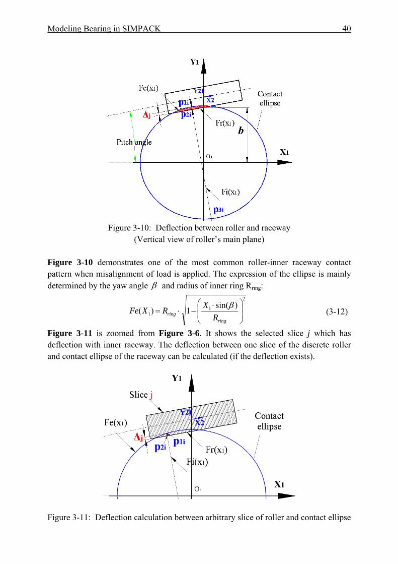
Modeling Bearing in SIMPACK 40
Figure 3-10: Deflection between roller and raceway
(Vertical view of roller’s main plane)
Figure 3-10 demonstrates one of the most common roller-inner raceway contact pattern when misalignment of load is applied. The expression of the ellipse is mainly determined by the yaw angle β and radius of inner ring Rring:
2
11
)sin(1)( ⎟⎟⎠
⎞⎜⎜⎝
⎛ ⋅−⋅=
ringring R
XRXFe β (3-12)
Figure 3-11 is zoomed from Figure 3-6. It shows the selected slice j which has deflection with inner raceway. The deflection between one slice of the discrete roller and contact ellipse of the raceway can be calculated (if the deflection exists).
Figure 3-11: Deflection calculation between arbitrary slice of roller and contact ellipse
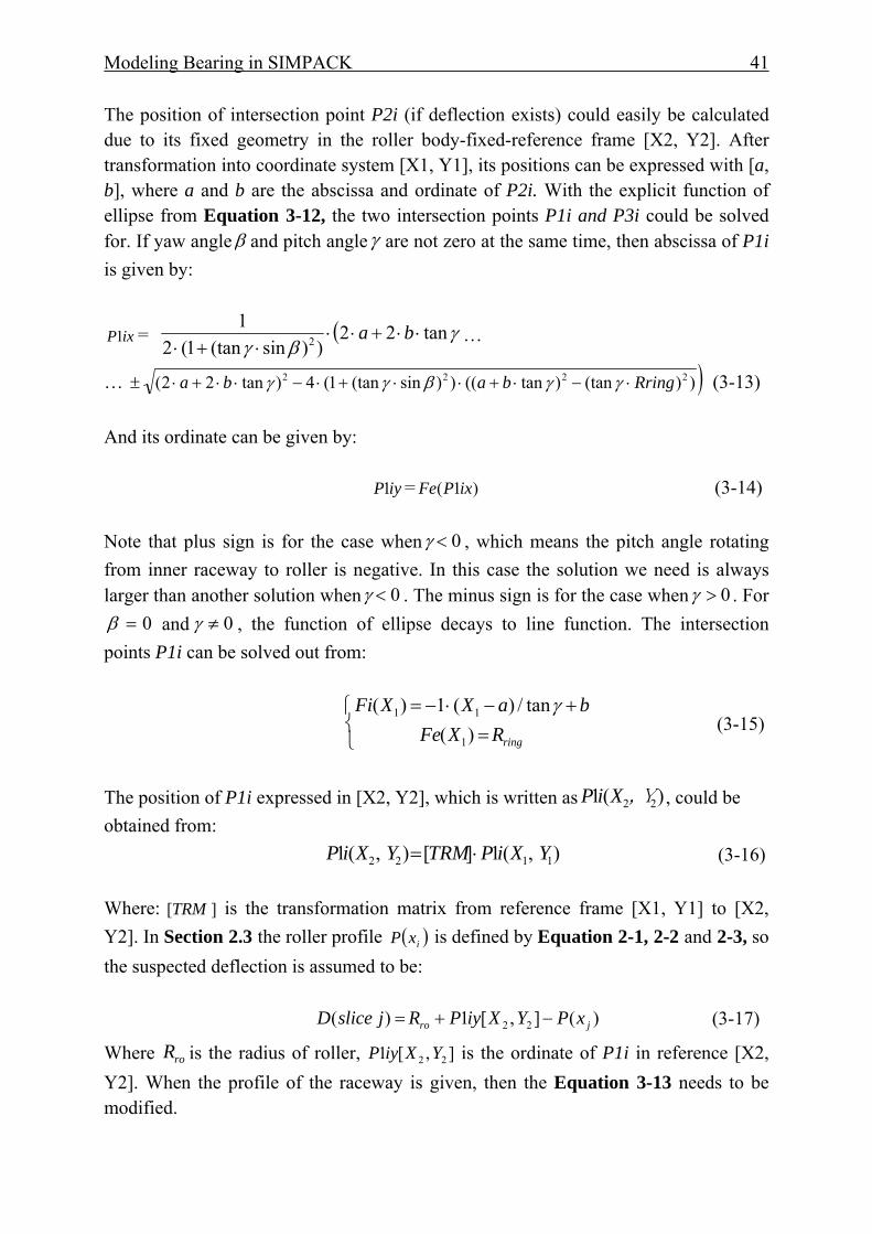
Modeling Bearing in SIMPACK 41
The position of intersection point P2i (if deflection exists) could easily be calculated due to its fixed geometry in the roller body-fixed-reference frame [X2, Y2]. After transformation into coordinate system [X1, Y1], its positions can be expressed with [a, b], where a and b are the abscissa and ordinate of P2i. With the explicit function of ellipse from Equation 3-12, the two intersection points P1i and P3i could be solved for. If yaw angleβ and pitch angleγ are not zero at the same time, then abscissa of P1i is given by:
ixP1 = ( γβγ
tan22))sin(tan1(2
12 ⋅⋅+⋅⋅
⋅+⋅ba …
… )))(tan)tan(())sin(tan1(4)tan22( 2222 Rringbaba ⋅−⋅+⋅⋅+⋅−⋅⋅+⋅± γγβγγ (3-13) And its ordinate can be given by: iyP1 = )1( ixPFe (3-14) Note that plus sign is for the case when 0<γ , which means the pitch angle rotating from inner raceway to roller is negative. In this case the solution we need is always larger than another solution when 0<γ . The minus sign is for the case when 0>γ . For
0=β and 0≠γ , the function of ellipse decays to line function. The intersection points P1i can be solved out from:
⎩⎨⎧
=+−⋅−=
ringRXFebaXXFi
)(tan/)(1)(
1
11 γ (3-15)
The position of P1i expressed in [X2, Y2], which is written as )(1 22,YXiP , could be obtained from: ) ,(1][) ,(1 1122 YXiPTRMYXiP ⋅= (3-16) Where: ][TRM is the transformation matrix from reference frame [X1, Y1] to [X2, Y2]. In Section 2.3 the roller profile ( )ixP is defined by Equation 2-1, 2-2 and 2-3, so the suspected deflection is assumed to be: )(] ,[1)( 22 jro xPYXiyPRjsliceD −+= (3-17)
Where roR is the radius of roller, ] ,[1 22 YXiyP is the ordinate of P1i in reference [X2, Y2]. When the profile of the raceway is given, then the Equation 3-13 needs to be modified.
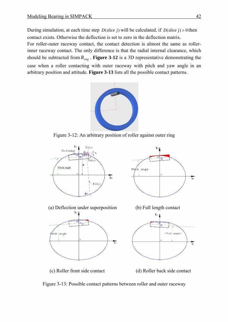
Modeling Bearing in SIMPACK 42
During simulation, at each time step )( jsliceD will be calculated, if 0)( >jsliceD then contact exists. Otherwise the deflection is set to zero in the deflection matrix. For roller-outer raceway contact, the contact detection is almost the same as roller-inner raceway contact. The only difference is that the radial internal clearance, which should be subtracted from ringR . Figure 3-12 is a 3D representative demonstrating the case when a roller contacting with outer raceway with pitch and yaw angle in an arbitrary position and attitude. Figure 3-13 lists all the possible contact patterns.
Figure 3-12: An arbitrary position of roller against outer ring
(a) Deflection under superposition (b) Full length contact
(c) Roller front side contact (d) Roller back side contact
Figure 3-13: Possible contact patterns between roller and outer raceway

Modeling Bearing in SIMPACK 43
These contact patterns between roller and outer raceway could happen at any simulation time point. As long as the deflection of any slice of the roller exists, the resulting contact force could be calculated.
3.5.3 Roller-Raceway Damping in Inlet Zone
Damping plays an important role when bearings are operated under oscillations. Thus a more detailed understanding of damping characteristics is needed for multi-body-systems. The major sources of damping in rolling bearings can be classified by following aspects [DWN00]:
(1) Oil damping in inlet zone of contacts between roller and raceway, roller and cage pocket.
(2) Material hysteresis damping due to the deformation of penetrated parts.
(3) Damping between bearing and its surroundings (such as housing and shaft). [Die97] has proposed an expression to calculate the damping which is defined as: fuqaELR K
eKK
DK
pKKK
äqK
xEHD fuqELRKD ⋅⋅⋅⋅⋅⋅⋅⋅⋅= Σ− αη η
003 '10 (3-18)
Where: :xR Reduced radius :'E Reduced elastic modulus
:Dq Load per slice :ef Inlet zone length factor
:0η Viscosity under air :Σu Sum of surface velocity :
äqL Contact length :pα Pressure viscosity coefficient
:,0 fuqaELR ,K,K,KK,K,K,K,KK η are constants in Table 3-2:
Table 3-2 Constants for damping calculation
There are many limitations for this empirical equation when evaluating the damping coefficient with different bearing types and load cases. That these constants are only valid in limited ranges makes this expression be far away from a continuous multi-body-simulation.
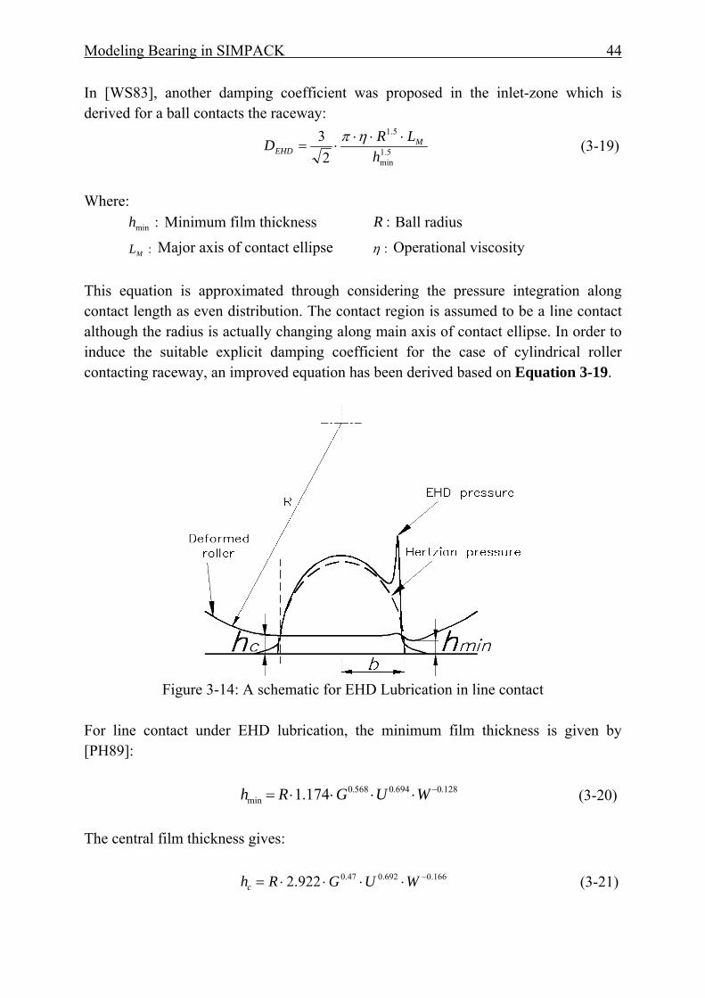
Modeling Bearing in SIMPACK 44
In [WS83], another damping coefficient was proposed in the inlet-zone which is derived for a ball contacts the raceway:
5.1min
5.1
23
hLRD M
EHD⋅⋅⋅
⋅=ηπ (3-19)
Where: :minh Minimum film thickness :R Ball radius
:ML Major axis of contact ellipse :η Operational viscosity This equation is approximated through considering the pressure integration along contact length as even distribution. The contact region is assumed to be a line contact although the radius is actually changing along main axis of contact ellipse. In order to induce the suitable explicit damping coefficient for the case of cylindrical roller contacting raceway, an improved equation has been derived based on Equation 3-19.
Figure 3-14: A schematic for EHD Lubrication in line contact
For line contact under EHD lubrication, the minimum film thickness is given by [PH89]: 128.0694.0568.0
min 174.1 −⋅⋅⋅⋅= WUGRh (3-20) The central film thickness gives: 166.0692.047.0922.2 −⋅⋅⋅⋅= WUGRhc (3-21)
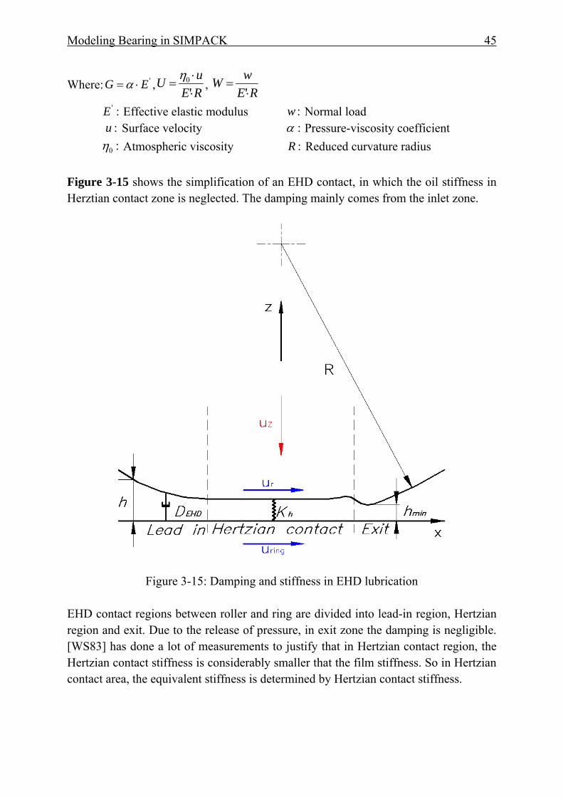
Modeling Bearing in SIMPACK 45
Where: 'EG ⋅= α ,REuU⋅⋅
='
0η , RE
wW⋅
='
:'E Effective elastic modulus :w Normal load :u Surface velocity :α Pressure-viscosity coefficient :0η Atmospheric viscosity :R Reduced curvature radius Figure 3-15 shows the simplification of an EHD contact, in which the oil stiffness in Herztian contact zone is neglected. The damping mainly comes from the inlet zone.
Figure 3-15: Damping and stiffness in EHD lubrication
EHD contact regions between roller and ring are divided into lead-in region, Hertzian region and exit. Due to the release of pressure, in exit zone the damping is negligible. [WS83] has done a lot of measurements to justify that in Hertzian contact region, the Hertzian contact stiffness is considerably smaller that the film stiffness. So in Hertzian contact area, the equivalent stiffness is determined by Hertzian contact stiffness.
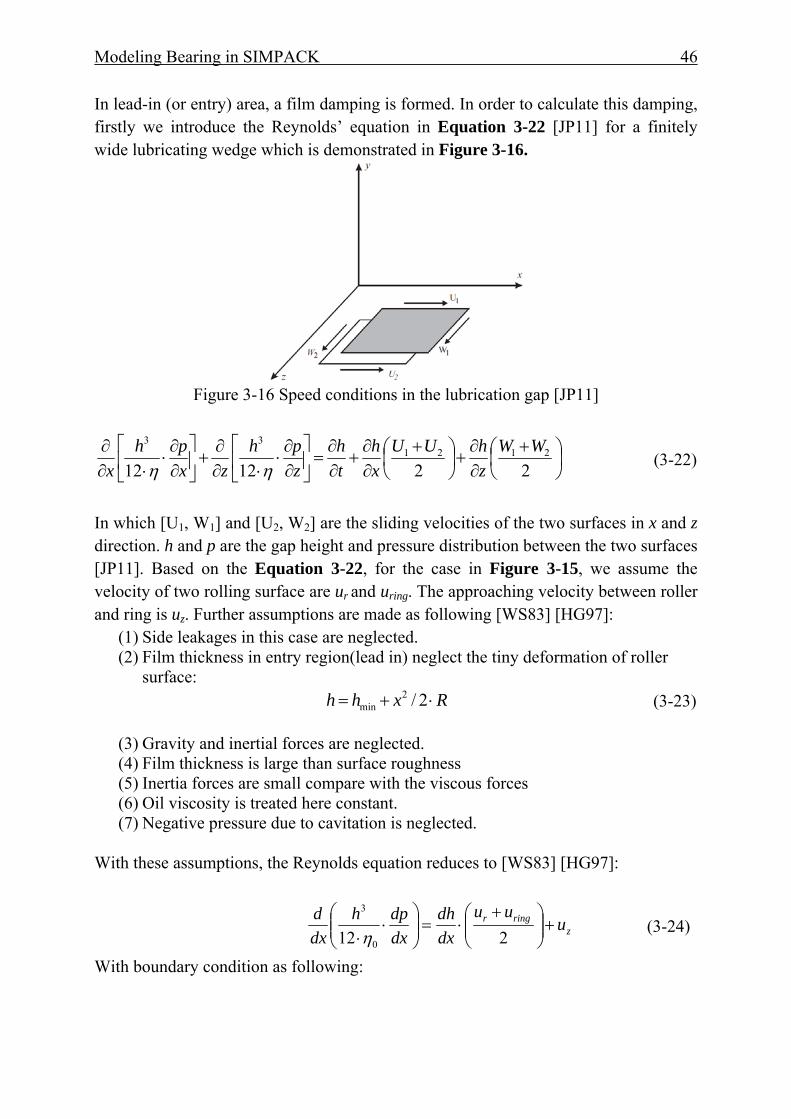
Modeling Bearing in SIMPACK 46
In lead-in (or entry) area, a film damping is formed. In order to calculate this damping, firstly we introduce the Reynolds’ equation in Equation 3-22 [JP11] for a finitely wide lubricating wedge which is demonstrated in Figure 3-16.
Figure 3-16 Speed conditions in the lubrication gap [JP11]
⎟⎠⎞
⎜⎝⎛ +
∂∂
+⎟⎠⎞
⎜⎝⎛ +
∂∂
+∂∂
=⎥⎦
⎤⎢⎣
⎡∂∂⋅
⋅∂∂
+⎥⎦
⎤⎢⎣
⎡∂∂⋅
⋅∂∂
2212122121
33 WWzhUU
xh
th
zph
zxph
x ηη (3-22)
In which [U1, W1] and [U2, W2] are the sliding velocities of the two surfaces in x and z direction. h and p are the gap height and pressure distribution between the two surfaces [JP11]. Based on the Equation 3-22, for the case in Figure 3-15, we assume the velocity of two rolling surface are ur and uring. The approaching velocity between roller and ring is uz. Further assumptions are made as following [WS83] [HG97]:
(1) Side leakages in this case are neglected. (2) Film thickness in entry region(lead in) neglect the tiny deformation of roller
surface: Rxhh ⋅+= 2/2
min (3-23)
(3) Gravity and inertial forces are neglected. (4) Film thickness is large than surface roughness (5) Inertia forces are small compare with the viscous forces (6) Oil viscosity is treated here constant. (7) Negative pressure due to cavitation is neglected.
With these assumptions, the Reynolds equation reduces to [WS83] [HG97]:
zringr u
uudxdh
dxdph
dxd
+⎟⎟⎠
⎞⎜⎜⎝
⎛ +⋅=⎟⎟
⎠
⎞⎜⎜⎝
⎛⋅
⋅ 212 0
3
η (3-24)
With boundary condition as following:
Modeling Bearing in SIMPACK 47
0∫∞
∞−
=dxdxdp (3-25)
After integrations, we obtain the oil pressure expression [WS83] [HG97]:
2223min
60
2222min
40
)(3
)(4
mxhmu
mxhxmup zx
+⋅⋅⋅⋅
−+⋅
⋅⋅⋅⋅−=
ηη (3-26)
Where: ringrx uuu += and:
min2 2 hRm ⋅⋅= (3-27)
The normal load is given by:
∫∞−
=0
pdxQ (3-28)
Due to the stress release in the exit zone, the effective damping source region should be end up with the central contact regions. So the integration limits is from ∞− to nearly 0. The total normal load is thus approximated to[WS83] [HG97]:
5.1min
5.10
min
0 66.6)(2h
LRuh
LRuuQ zringr ⋅⋅⋅⋅
+⋅⋅+⋅⋅
=ηη
(3-29)
In the right side of Equation 3-29, the left expression has a physical meaning and could be considered as applied load on roller and raceway. The later expression contributes to the damping characteristics when there is an oscillation between roller and raceway’s contact. Till now the derived expression for evaluating the damping are completely identical to the equations in [WS83] and [HG97]. The main difference is that, in their works, assumption for main ellipse axis in ball-raceway contact is not assumption anymore, but quite suitable for cylinder roller-raceway line contact. This equation is therefore adopted for the calculation damping force when the EHD lubrication is presented.
3.6 Roller-Pocket Contact
3.6.1 Roller-Pocket Contact Stiffness
Stress magnitude and distribution in the cage cross bar is one of the key factors in cage design. Special care should be given in this issue. Most of the publications have assumed a rigid cage, or partly considering the cage flexibility, still neglecting the

Modeling Bearing in SIMPACK 48
roller-pocket contact stiffness. Thus large forces between roller and pocket are calculated and these overestimated forces will in return affect the cage slip and also cage stability. Besides, traditional calculation of contact stiffness between roller and pocket through Hertzian line-contact expressions will generate unrealistic values. For example when a roller made of steel contacts a cage that is made of polyimide which has a much smaller elastic modulus, will result in nearly 100 times higher contact stiffness than the real stiffness. Houpert developed a dynamical simulation tool, which is called CAGEDYN, in which more realistic roller-pocket contact forces are calculated through the equivalent stiffness between roller center and pocket bridge center[Hou10a] [Hou10b] [Hou10c].
Figure 3-17: Local contact stiffness between roller and bridge of cage pocket
Figure 3-18: Possible representative contact points between roller and pocket The drawback of Houpert’s model lies in the calculating equivalent stiffness between roller and pocket. The kinematic energy and auxiliary tool IMPACT6 are not easy to be obtained. Figure 3-17 shows the schematic of a roller contacting the cage pocket bridge. In this work, in order to avoid measurements and drawbacks of Houpert’s model, FE analysis is employed as an effective alternative method to obtain the contact stiffness between roller and cage pocket, although the approaching velocity is not considered. In this method, some assumptions are made when considering the pocket detailed geometry:
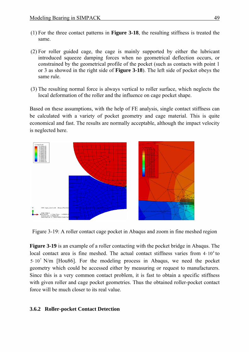
Modeling Bearing in SIMPACK 49
(1) For the three contact patterns in Figure 3-18, the resulting stiffness is treated the same.
(2) For roller guided cage, the cage is mainly supported by either the lubricant introduced squeeze damping forces when no geometrical deflection occurs, or constrained by the geometrical profile of the pocket (such as contacts with point 1 or 3 as showed in the right side of Figure 3-18). The left side of pocket obeys the same rule.
(3) The resulting normal force is always vertical to roller surface, which neglects the
local deformation of the roller and the influence on cage pocket shape. Based on these assumptions, with the help of FE analysis, single contact stiffness can be calculated with a variety of pocket geometry and cage material. This is quite economical and fast. The results are normally acceptable, although the impact velocity is neglected here.
Figure 3-19: A roller contact cage pocket in Abaqus and zoom in fine meshed region
Figure 3-19 is an example of a roller contacting with the pocket bridge in Abaqus. The local contact area is fine meshed. The actual contact stiffness varies from 4104 ⋅ to
7105 ⋅ N/m [Hou86]. For the modeling process in Abaqus, we need the pocket geometry which could be accessed either by measuring or request to manufacturers. Since this is a very common contact problem, it is fast to obtain a specific stiffness with given roller and cage pocket geometries. Thus the obtained roller-pocket contact force will be much closer to its real value.
3.6.2 Roller-pocket Contact Detection
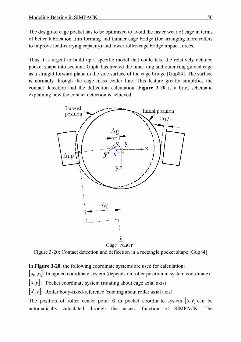
Modeling Bearing in SIMPACK 50
The design of cage pocket has to be optimized to avoid the faster wear of cage in terms of better lubrication film forming and thinner cage bridge (for arranging more rollers to improve load-carrying capacity) and lower roller-cage bridge impact forces. Thus it is urgent to build up a specific model that could take the relatively detailed pocket shape into account. Gupta has treated the inner ring and outer ring guided cage as a straight forward plane in the side surface of the cage bridge [Gup84]. The surface is normally through the cage mass center line. This feature greatly simplifies the contact detection and the deflection calculation. Figure 3-20 is a brief schematic explaining how the contact detection is achieved.
Figure 3-20: Contact detection and deflection in a rectangle pocket shape [Gup84]
In Figure 3-20, the following coordinate systems are used for calculation: [ ]ii,yx : Imagined coordinate system (depends on roller position in system coordinate)
[ ]yx, : Pocket coordinate system (rotating about cage axial axis) [ ]'' y,x : Roller body-fixed-reference (rotating about roller axial axis)
The position of roller center point 'O in pocket coordinate system [ ]yx, can be automatically calculated through the access function of SIMPACK. The
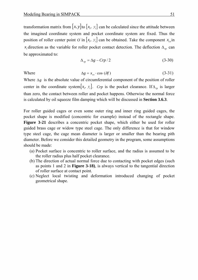
Modeling Bearing in SIMPACK 51
transformation matrix from [ ]yx, to [ ]ii,yx can be calculated since the attitude between the imagined coordinate system and pocket coordinate system are fixed. Thus the position of roller center point 'O in [ ]ii,yx can be obtained. Take the component cxx in
ix direction as the variable for roller pocket contact detection. The deflection rpΔ can be approximated to: 2/Crpgrp −Δ=Δ (3-30) Where )(cos fxg cx ϑ⋅⋅=Δ (3-31) Where gΔ is the absolute value of circumferential component of the position of roller center in the coordinate system [ ]ii,yx . Crp is the pocket clearance. If rpΔ is larger than zero, the contact between roller and pocket happens. Otherwise the normal force is calculated by oil squeeze film damping which will be discussed in Section 3.6.3. For roller guided cages or even some outer ring and inner ring guided cages, the pocket shape is modified (concentric for example) instead of the rectangle shape. Figure 3-21 describes a concentric pocket shape, which either be used for roller guided brass cage or widow type steel cage. The only difference is that for window type steel cage, the cage mean diameter is larger or smaller than the bearing pith diameter. Before we consider this detailed geometry in the program, some assumptions should be made:
(a) Pocket surface is concentric to roller surface, and the radius is assumed to be the roller radius plus half pocket clearance.
(b) The direction of actual normal force due to contacting with pocket edges (such as points 1 and 2 in Figure 3-18), is always vertical to the tangential direction of roller surface at contact point.
(c) Neglect local twisting and deformation introduced changing of pocket geometrical shape.
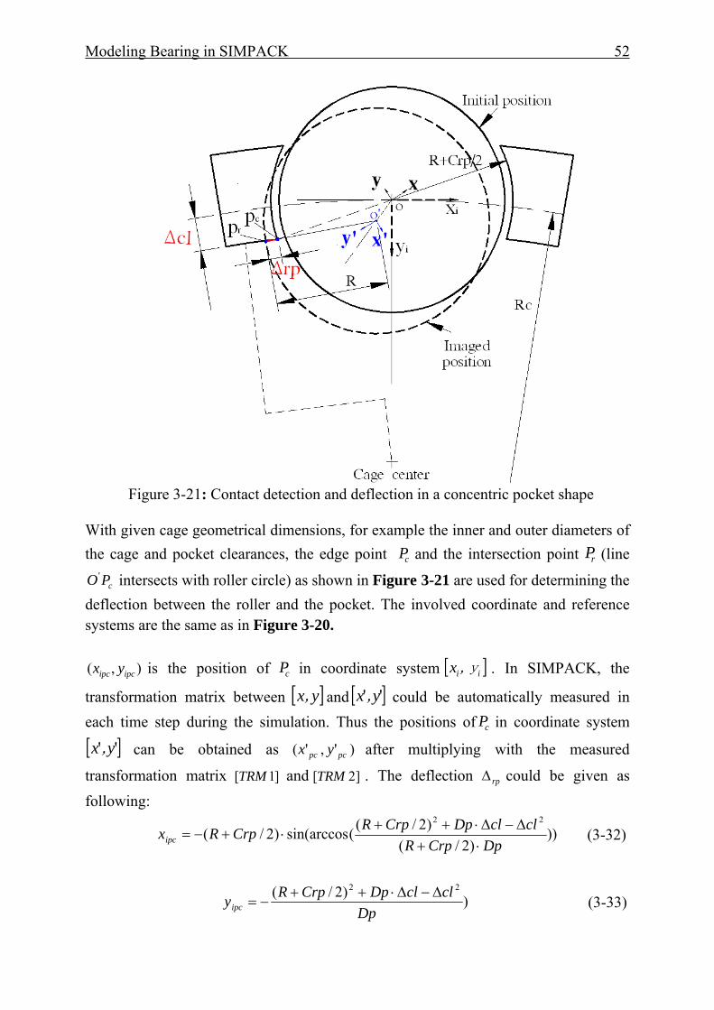
Modeling Bearing in SIMPACK 52
Figure 3-21: Contact detection and deflection in a concentric pocket shape
With given cage geometrical dimensions, for example the inner and outer diameters of the cage and pocket clearances, the edge point cP and the intersection point rP (line
cPO ' intersects with roller circle) as shown in Figure 3-21 are used for determining the deflection between the roller and the pocket. The involved coordinate and reference systems are the same as in Figure 3-20.
),( ipcipc yx is the position of cP in coordinate system [ ]ii,yx . In SIMPACK, the
transformation matrix between [ ]yx, and [ ]'' y,x could be automatically measured in each time step during the simulation. Thus the positions of cP in coordinate system
[ ]'' y,x can be obtained as )','( pcpc yx after multiplying with the measured
transformation matrix ]1[TRM and ]2[TRM . The deflection rpΔ could be given as following:
)))2/(
)2/((sin(arccos)2/(22
DpCrpRclclDpCrpRCrpRxipc ⋅+
Δ−Δ⋅++⋅+−= (3-32)
))2/( 22
DpclclDpCrpRyipc
Δ−Δ⋅++−= (3-33)
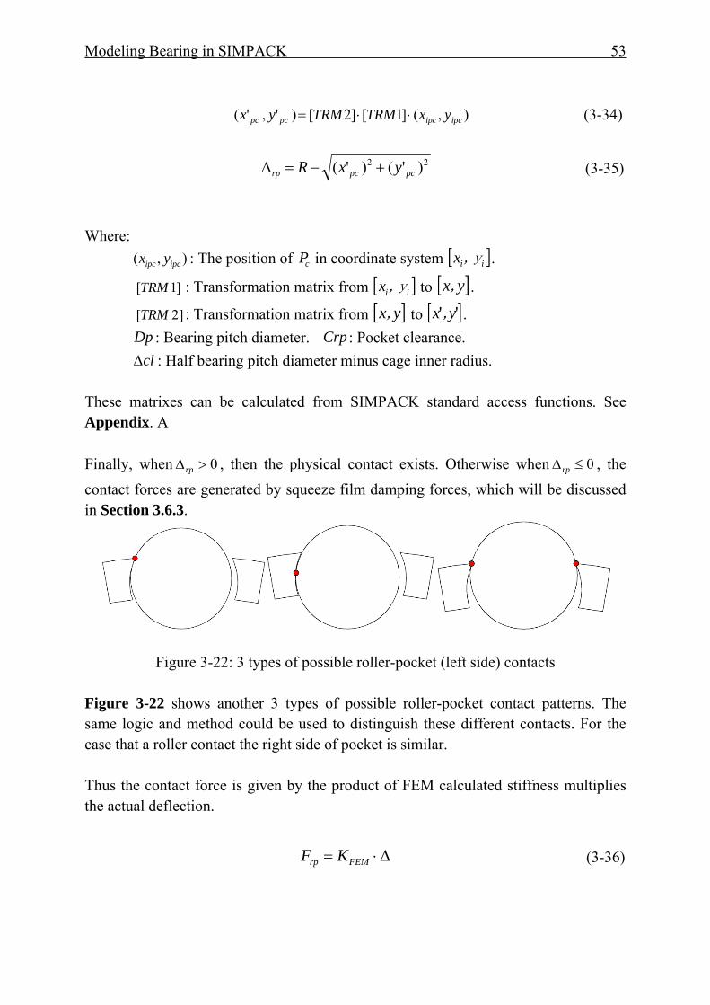
Modeling Bearing in SIMPACK 53
),(]1[]2[)','( ipcipcpcpc yxTRMTRMyx ⋅⋅= (3-34)
22 )'()'( pcpcrp yxR +−=Δ (3-35)
Where: ),( ipcipc yx : The position of cP in coordinate system [ ]ii,yx .
]1[TRM : Transformation matrix from [ ]ii,yx to [ ]yx, .
]2[TRM : Transformation matrix from [ ]yx, to [ ]'' y,x . Dp : Bearing pitch diameter. Crp : Pocket clearance. clΔ : Half bearing pitch diameter minus cage inner radius. These matrixes can be calculated from SIMPACK standard access functions. See Appendix. A Finally, when 0>Δrp , then the physical contact exists. Otherwise when 0≤Δrp , the contact forces are generated by squeeze film damping forces, which will be discussed in Section 3.6.3.
Figure 3-22: 3 types of possible roller-pocket (left side) contacts
Figure 3-22 shows another 3 types of possible roller-pocket contact patterns. The same logic and method could be used to distinguish these different contacts. For the case that a roller contact the right side of pocket is similar. Thus the contact force is given by the product of FEM calculated stiffness multiplies the actual deflection.
Δ⋅= FEMrp KF (3-36)
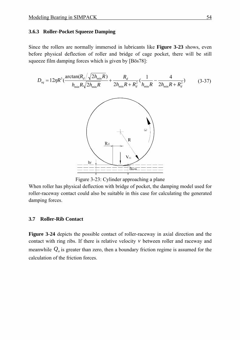
Modeling Bearing in SIMPACK 54
3.6.3 Roller-Pocket Squeeze Damping Since the rollers are normally immersed in lubricants like Figure 3-23 shows, even before physical deflection of roller and bridge of cage pocket, there will be still squeeze film damping forces which is given by [Bös78]:
)2
41(22
)2arctan((12 2
minmin2
minminmin
min3
dd
ddsq RRhRhRRh
RRhRh
RhRRD
+−
++= η (3-37)
Figure 3-23: Cylinder approaching a plane
When roller has physical deflection with bridge of pocket, the damping model used for roller-raceway contact could also be suitable in this case for calculating the generated damping forces.
3.7 Roller-Rib Contact Figure 3-24 depicts the possible contact of roller-raceway in axial direction and the contact with ring ribs. If there is relative velocity v between roller and raceway and meanwhile oQ is greater than zero, then a boundary friction regime is assumed for the calculation of the friction forces.
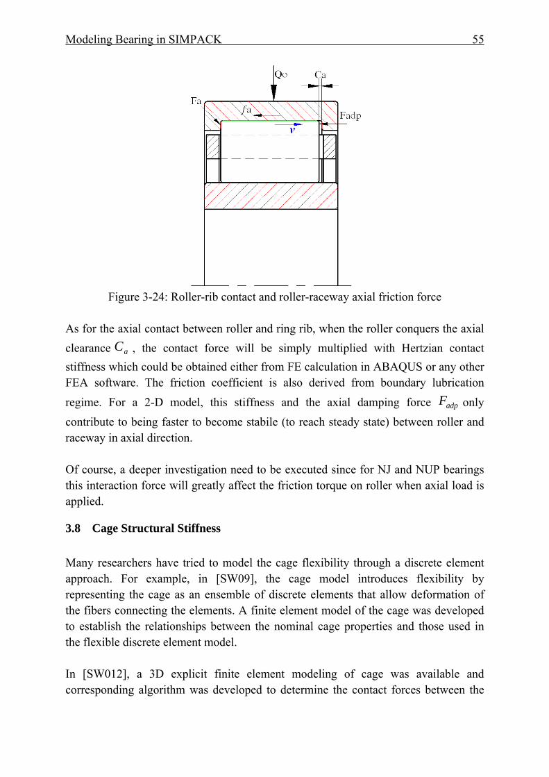
Modeling Bearing in SIMPACK 55
Figure 3-24: Roller-rib contact and roller-raceway axial friction force
As for the axial contact between roller and ring rib, when the roller conquers the axial clearance aC , the contact force will be simply multiplied with Hertzian contact stiffness which could be obtained either from FE calculation in ABAQUS or any other FEA software. The friction coefficient is also derived from boundary lubrication regime. For a 2-D model, this stiffness and the axial damping force adpF only contribute to being faster to become stabile (to reach steady state) between roller and raceway in axial direction. Of course, a deeper investigation need to be executed since for NJ and NUP bearings this interaction force will greatly affect the friction torque on roller when axial load is applied.
3.8 Cage Structural Stiffness Many researchers have tried to model the cage flexibility through a discrete element approach. For example, in [SW09], the cage model introduces flexibility by representing the cage as an ensemble of discrete elements that allow deformation of the fibers connecting the elements. A finite element model of the cage was developed to establish the relationships between the nominal cage properties and those used in the flexible discrete element model. In [SW012], a 3D explicit finite element modeling of cage was available and corresponding algorithm was developed to determine the contact forces between the
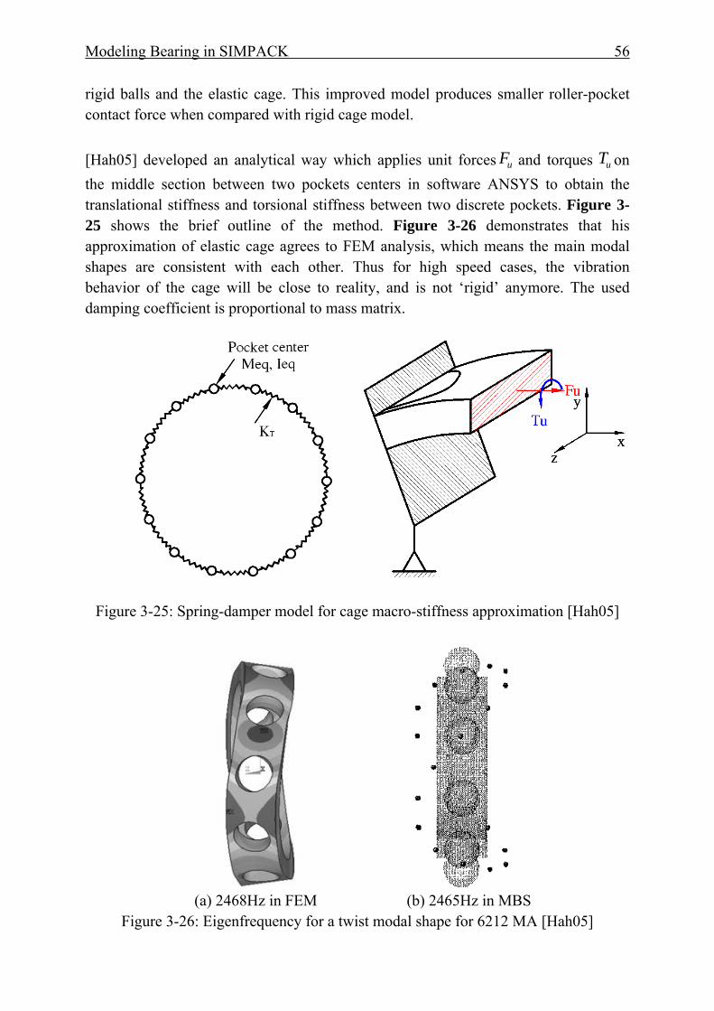
Modeling Bearing in SIMPACK 56
rigid balls and the elastic cage. This improved model produces smaller roller-pocket contact force when compared with rigid cage model. [Hah05] developed an analytical way which applies unit forces uF and torques uT on the middle section between two pockets centers in software ANSYS to obtain the translational stiffness and torsional stiffness between two discrete pockets. Figure 3-25 shows the brief outline of the method. Figure 3-26 demonstrates that his approximation of elastic cage agrees to FEM analysis, which means the main modal shapes are consistent with each other. Thus for high speed cases, the vibration behavior of the cage will be close to reality, and is not ‘rigid’ anymore. The used damping coefficient is proportional to mass matrix.
Figure 3-25: Spring-damper model for cage macro-stiffness approximation [Hah05]
(a) 2468Hz in FEM (b) 2465Hz in MBS
Figure 3-26: Eigenfrequency for a twist modal shape for 6212 MA [Hah05]
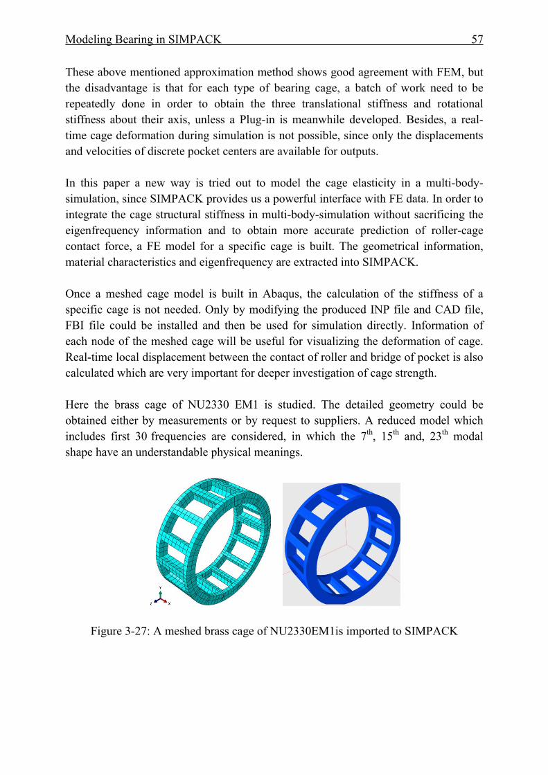
Modeling Bearing in SIMPACK 57
These above mentioned approximation method shows good agreement with FEM, but the disadvantage is that for each type of bearing cage, a batch of work need to be repeatedly done in order to obtain the three translational stiffness and rotational stiffness about their axis, unless a Plug-in is meanwhile developed. Besides, a real-time cage deformation during simulation is not possible, since only the displacements and velocities of discrete pocket centers are available for outputs.
In this paper a new way is tried out to model the cage elasticity in a multi-body-simulation, since SIMPACK provides us a powerful interface with FE data. In order to integrate the cage structural stiffness in multi-body-simulation without sacrificing the eigenfrequency information and to obtain more accurate prediction of roller-cage contact force, a FE model for a specific cage is built. The geometrical information, material characteristics and eigenfrequency are extracted into SIMPACK. Once a meshed cage model is built in Abaqus, the calculation of the stiffness of a specific cage is not needed. Only by modifying the produced INP file and CAD file, FBI file could be installed and then be used for simulation directly. Information of each node of the meshed cage will be useful for visualizing the deformation of cage. Real-time local displacement between the contact of roller and bridge of pocket is also calculated which are very important for deeper investigation of cage strength. Here the brass cage of NU2330 EM1 is studied. The detailed geometry could be obtained either by measurements or by request to suppliers. A reduced model which includes first 30 frequencies are considered, in which the 7th, 15th and, 23th modal shape have an understandable physical meanings.
Figure 3-27: A meshed brass cage of NU2330EM1is imported to SIMPACK
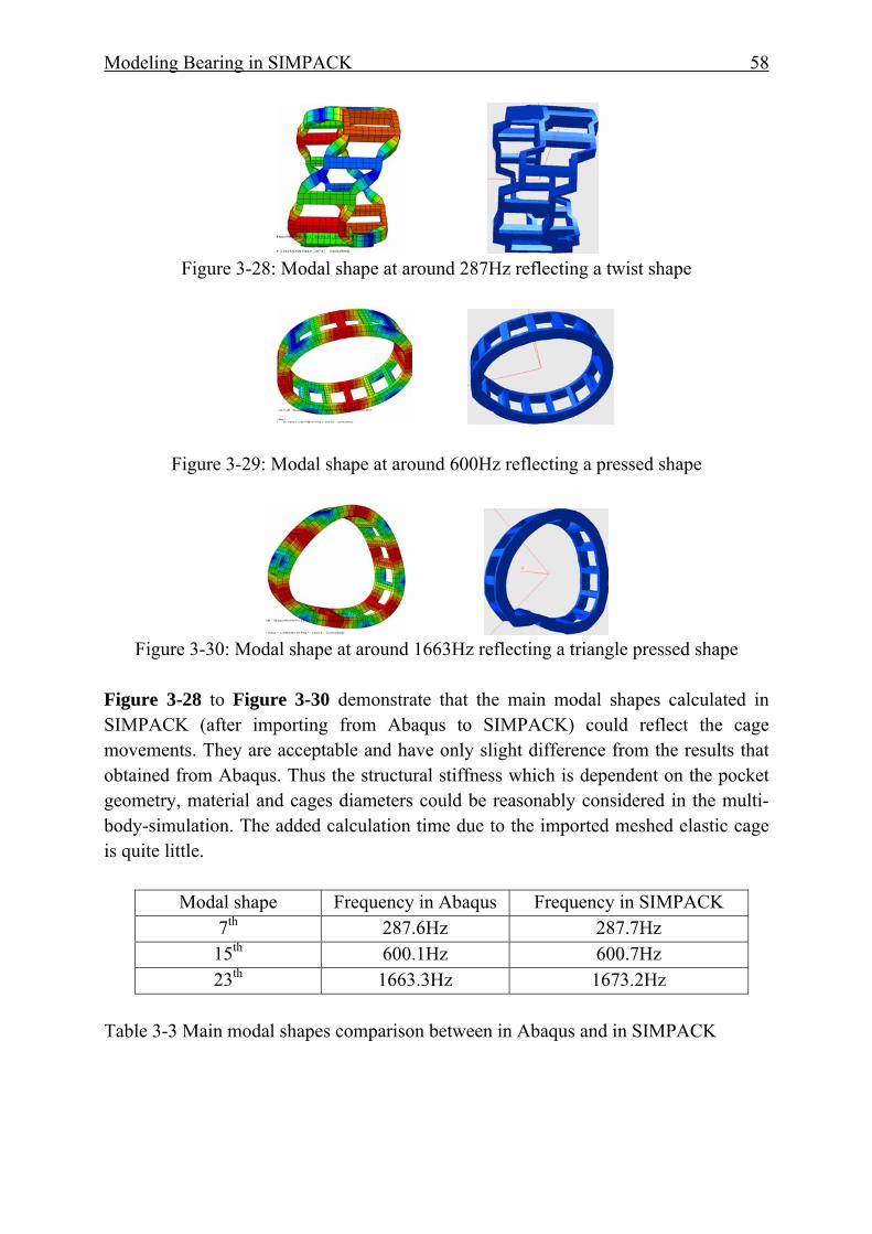
Modeling Bearing in SIMPACK 58
Figure 3-28: Modal shape at around 287Hz reflecting a twist shape
Figure 3-29: Modal shape at around 600Hz reflecting a pressed shape
Figure 3-30: Modal shape at around 1663Hz reflecting a triangle pressed shape
Figure 3-28 to Figure 3-30 demonstrate that the main modal shapes calculated in SIMPACK (after importing from Abaqus to SIMPACK) could reflect the cage movements. They are acceptable and have only slight difference from the results that obtained from Abaqus. Thus the structural stiffness which is dependent on the pocket geometry, material and cages diameters could be reasonably considered in the multi-body-simulation. The added calculation time due to the imported meshed elastic cage is quite little.
Modal shape Frequency in Abaqus Frequency in SIMPACK 7th 287.6Hz 287.7Hz 15th 600.1Hz 600.7Hz 23th 1663.3Hz 1673.2Hz
Table 3-3 Main modal shapes comparison between in Abaqus and in SIMPACK
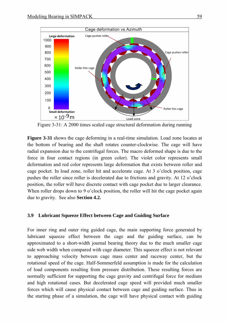
Modeling Bearing in SIMPACK 59
Figure 3-31: A 2000 times scaled cage structural deformation during running
Figure 3-31 shows the cage deforming in a real-time simulation. Load zone locates at the bottom of bearing and the shaft rotates counter-clockwise. The cage will have radial expansion due to the centrifugal forces. The macro deformed shape is due to the force in four contact regions (in green color). The violet color represents small deformation and red color represents large deformation that exists between roller and cage pocket. In load zone, roller hit and accelerate cage. At 3 o’clock position, cage pushes the roller since roller is decelerated due to frictions and gravity. At 12 o’clock position, the roller will have discrete contact with cage pocket due to larger clearance. When roller drops down to 9 o’clock position, the roller will hit the cage pocket again due to gravity. See also Section 4.2.
3.9 Lubricant Squeeze Effect between Cage and Guiding Surface For inner ring and outer ring guided cage, the main supporting force generated by lubricant squeeze effect between the cage and the guiding surface, can be approximated to a short-width journal bearing theory due to the much smaller cage side web width when compared with cage diameter. This squeeze effect is not relevant to approaching velocity between cage mass center and raceway center, but the rotational speed of the cage. Half-Sommerfeld assumption is made for the calculation of load components resulting from pressure distribution. These resulting forces are normally sufficient for supporting the cage gravity and centrifugal force for medium and high rotational cases. But decelerated cage speed will provided much smaller forces which will cause physical contact between cage and guiding surface. Thus in the starting phase of a simulation, the cage will have physical contact with guiding
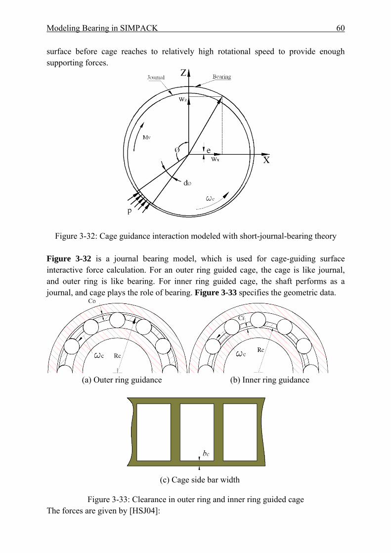
Modeling Bearing in SIMPACK 60
surface before cage reaches to relatively high rotational speed to provide enough supporting forces.
Figure 3-32: Cage guidance interaction modeled with short-journal-bearing theory
Figure 3-32 is a journal bearing model, which is used for cage-guiding surface interactive force calculation. For an outer ring guided cage, the cage is like journal, and outer ring is like bearing. For inner ring guided cage, the shaft performs as a journal, and cage plays the role of bearing. Figure 3-33 specifies the geometric data.
(a) Outer ring guidance (b) Inner ring guidance
(c) Cage side bar width
Figure 3-33: Clearance in outer ring and inner ring guided cage The forces are given by [HSJ04]:
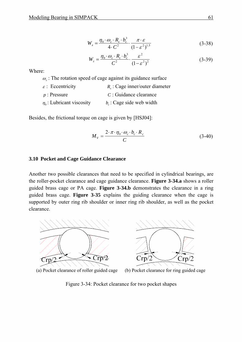
Modeling Bearing in SIMPACK 61
5.122
30
)1(4 εεπωη
−⋅
⋅⋅
⋅⋅⋅=
CbRW ccc
x (3-38)
22
2
2
30
)1( εεωη−
⋅⋅⋅⋅
=C
bRW cccz (3-39)
Where: cω : The rotation speed of cage against its guidance surface ε : Eccentricity cR : Cage inner/outer diameter p : Pressure C : Guidance clearance 0η : Lubricant viscosity cb : Cage side web width Besides, the frictional torque on cage is given by [HSJ04]:
C
RbM ccc
V
⋅⋅⋅⋅⋅=
ωηπ 02 (3-40)
3.10 Pocket and Cage Guidance Clearance Another two possible clearances that need to be specified in cylindrical bearings, are the roller-pocket clearance and cage guidance clearance. Figure 3-34.a shows a roller guided brass cage or PA cage. Figure 3-34.b demonstrates the clearance in a ring guided brass cage. Figure 3-35 explains the guiding clearance when the cage is supported by outer ring rib shoulder or inner ring rib shoulder, as well as the pocket clearance.
(a) Pocket clearance of roller guided cage (b) Pocket clearance for ring guided cage
Figure 3-34: Pocket clearance for two pocket shapes

Modeling Bearing in SIMPACK 62
(a) Outer ring guided cage (b) Inner ring guided cage
Figure 3-35: Inner ring or outer ring guiding clearances and their pocket clearances
3.11 Drag Force Due to Lubricant
Figure 3-36: Drag force on the cylindrical surface
Generally, the force exerted on the bearing element as it translates through the lubricant is called drag; the moment imposed due to rotation of the element in the lubricant is called churning [Gup84]. Due to the uncertainty of the actual immersed oil, it is not an easy task to estimate the exact influence. Here a drag coefficient DC [Sch68] is defined to describe this effect:
AV
FC drag
D
⋅⋅⋅=
2
21 ρ
(3-41)
Where: A is the frontal area expressed by the body in the oil flow direction. In cylindrical roller bearings, this area can be expressed as: )( cr TDLA −⋅= (3-42)
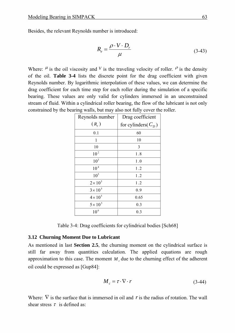
Modeling Bearing in SIMPACK 63
Besides, the relevant Reynolds number is introduced:
μρ r
eDVR ⋅⋅
= (3-43)
Where: μ is the oil viscosity and V is the traveling velocity of roller. ρ is the density of the oil. Table 3-4 lists the discrete point for the drag coefficient with given Reynolds number. By logarithmic interpolation of these values, we can determine the drag coefficient for each time step for each roller during the simulation of a specific bearing. These values are only valid for cylinders immersed in an unconstrained stream of fluid. Within a cylindrical roller bearing, the flow of the lubricant is not only constrained by the bearing walls, but may also not fully cover the roller.
Reynolds number ( eR )
Drag coefficient for cylinders( DC )
1.0 60 1 10
10 3 210 8.1 310 0.1 410 2.1 510 2.1
5102× 2.1 5103× 9.0 5104× 65.0 5105× 3.0
610 3.0
Table 3-4: Drag coefficients for cylindrical bodies [Sch68]
3.12 Churning Moment Due to Lubricant As mentioned in last Section 2.5, the churning moment on the cylindrical surface is still far away from quantities calculation. The applied equations are rough approximation to this case. The moment cM due to the churning effect of the adherent oil could be expressed as [Gup84]: rM c ⋅∇⋅=τ (3-44) Where: ∇ is the surface that is immersed in oil and r is the radius of rotation. The wall shear stress τ is defined as:
Modeling Bearing in SIMPACK 64
2ˆ
21 Uf ⋅⋅⋅= ρτ (3-45)
Where: ρ is the mass density and U is the mass average velocity of the fluid. The
friction factor f̂ , which is defined as:
539474.0
41413.1ˆ
>
⎟⎠⎞
⎜⎝⎛⋅=
T
aTf (3-46)
85596.0
250025000.3ˆ
>
⎟⎠⎞
⎜⎝⎛⋅=
eR
eRf (3-47)
In typical high-speed cylindrical roller bearings, Coquettes turbulent flow is dominant on the cage surface, thus Equation 3-46 is used for calculating the churning moment on cage. Vortex turbulent flow is assumed for roller surfaces and Equation 3-47 is used for the resulting moment on it. Besides the Reynolds number and Taylor number are defined here for judging different flows which are defined as:
μωρ crRe⋅⋅⋅
= (3-48)
rccrTa ⋅
⋅⋅⋅=
μωρ
(3-49)
Where: ω is the angular velocity in the stationary housing and c is the pocket
clearance. For 2500<eR or 41<aT :
eRf 16ˆ = (3-50) Please note that both the drag force and churning moment are approximated for tendency prediction. A more sophisticated model needs to be developed specially for this issue.
3.13 Material Hysteresis Damping Aforementioned damping is mainly due to lubricants. Apart from that, the material damping should also be taken into account since there are so many contacts between components and the energy dissipation should not be neglected [HC75][HM76].
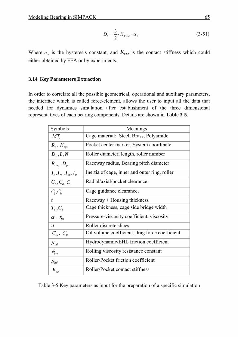
Modeling Bearing in SIMPACK 65
eFEMh KD α⋅⋅=23 (3-51)
Where eα is the hysteresis constant, and FEMK is the contact stiffness which could either obtained by FEA or by experiments.
3.14 Key Parameters Extraction In order to correlate all the possible geometrical, operational and auxiliary parameters, the interface which is called force-element, allows the user to input all the data that needed for dynamics simulation after establishment of the three dimensional representatives of each bearing components. Details are shown in Table 3-5.
Symbols Meanings
cMT Cage material: Steel, Brass, Polyamide
sysp,RR Pocket center marker, System coordinate
NLD r ,, Roller diameter, length, roller number
pring DR , Raceway radius, Bearing pitch diameter
irorroc IIII ,,, Inertia of cage, inner and outer ring, roller
ar CC , rpC Radial/axial/pocket clearance
oi CC , Cage guidance clearance,
t Raceway + Housing thickness
sc CT , Cage thickness, cage side bridge width
0ηα, Pressure-viscosity coefficient, viscosity
n Roller discrete slices
Dov,CC Oil volume coefficient, drag force coefficient
hdμ Hydrodynamic/EHL friction coefficient
rvrφ Rolling viscosity resistance constant
bdμ Roller/Pocket friction coefficient
rpK Roller/Pocket contact stiffness
Table 3-5 Key parameters as input for the preparation of a specific simulation
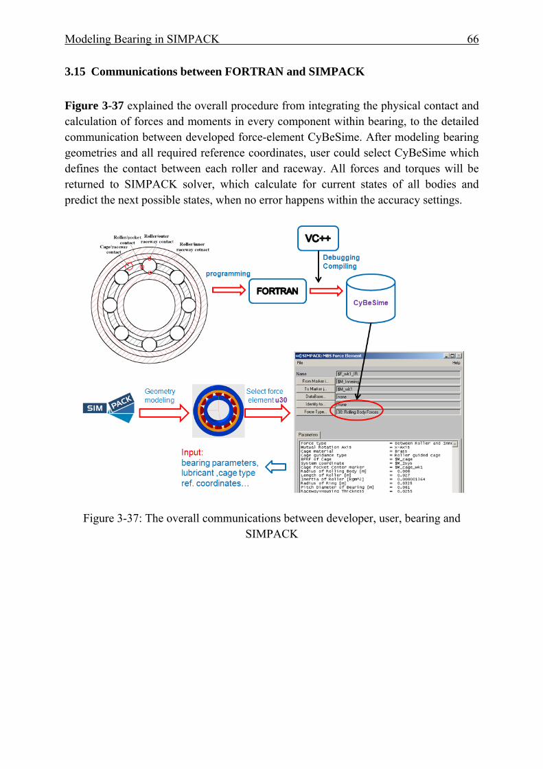
Modeling Bearing in SIMPACK 66
3.15 Communications between FORTRAN and SIMPACK
Figure 3-37 explained the overall procedure from integrating the physical contact and calculation of forces and moments in every component within bearing, to the detailed communication between developed force-element CyBeSime. After modeling bearing geometries and all required reference coordinates, user could select CyBeSime which defines the contact between each roller and raceway. All forces and torques will be returned to SIMPACK solver, which calculate for current states of all bodies and predict the next possible states, when no error happens within the accuracy settings.
Figure 3-37: The overall communications between developer, user, bearing and SIMPACK
Modeling Bearing in SIMPACK 67
3.16 Chapter Summary
In this chapter, the technique to design the bearing calculation model in SIMPACK and the advanced aspects of cylindrical bearings are introduced. Regarding modeling bearing in SIMPACK, from Section 1.1 to Section 1.3, a system flow chart is drawn to demonstrate that what real-time variables can be accessed and used for the description of the attitudes of rollers, cage, inner ring and outer ring. With the help of this information, the contact detection and resulting forces and moments between parts can be derived. Since the rollers of cylindrical bearings are discrete to many slices, the kinematics and dynamics of each slice are separately considered. From Section 3.4 to Section 3.8, the contact detections between roller and raceway are similar to Teutsch’s method but the detailed penetration calculation between roller and raceway is simpler. Furthermore, the contact detection between roller and cage pocket are mathematically derived when considering the pocket shape (concentric to roller). The contact stiffness between roller and raceway uses an explicit load-deflection relationship and the so-called Alternative Slice Technique to reflect the more realistic load distribution along the roller contact length. The damping forces are derived from reduced equations of EHL neglecting the change of temperature and viscosity of the lubricant. For the contact between roller and pocket, the same slice model is used. The local contact stiffness between roller and cage pocket comes from the FE analysis. The details of the pocket geometry of roller-guided cages are considered. The damping calculation employs the squeeze film damping equation when no contacts exist. When contact exists the damping forces are calculated with the same method as the roller-raceway contacts.
For bearings that have an inner ring or outer ring guided cage, the contact between cage and its guiding surfaces are approximated to a journal bearing model. Regarding the advanced aspects of bearing, the pocket and cage guidance clearances are considered in the bearing calculation program CyBeSime. The cage macro-stiffness is considered through importing the reduced FE model to SIMPCAK. Roller-rib contacts are also considered but the stiffness and contact detections are simplified. Other non-linear effects such as the drag forces and churning moments that are acting on roller and cage surfaces are also considered. Furthermore, the material hysteresis damping forces are calculated in all contacts as long as deformations between two bodies take place.
Modeling Bearing in SIMPACK 68
To fulfill the above mentioned functionalities and aspects, the key parameters are thus extracted as input in the graphical user interface. Finally the overview from development stage (programming) to final application is shown. The main contributions are summarized as following:
(1) A good combination of basic functionalities from existing bearing simulation programs.
(2) Take the pocket geometry into account as well as three types of cage guidance.
(3) Use FE analysis for obtaining roller-pocket contact stiffness.
(4) Cage macro-stiffness is considered through importing the reduced FE model to SIMPCAK, which keep the most modal information of cage.

Validation of CyBeSime 69
4 Validation of CyBeSime
4.1 Cage Mass Center Orbit Compared with Measurements Whether the cage mass center will be become stabile or not, is important for further investigation of cage behavior, since the resulting contact forces between roller and bridge of pocket could have different characteristics and magnitudes. Cage center position of NU 2310 G1 is simulated under 980N upwards radial load on the outer ring. This experiment was originally executed by [SU04]. In Figure 4-1, the cage orbit after some time of running, is stable under 3000 rpm and 5000 rpm.
Figure 4-1: Schematic of the loading on outer ring [SU04]
Bearing Geometry
Bearing Type NU2310G1 Bore diameter 50mm Number of rollers 12 Radial clearance 0.045mm Cage landing clearance 0.445mm/outer ring guidance
Material Rollers and races Steel Cage Brass(machined)
Operating conditions Inner ring speed 1000,3000, 5000rpm Radial load 980,4900N
Table 4-1: Bearing geometry, material and operating condition used for simulation
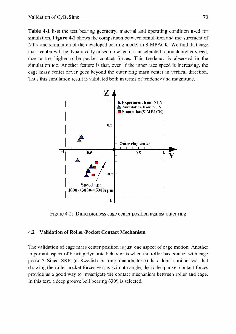
Validation of CyBeSime 70
Table 4-1 lists the test bearing geometry, material and operating condition used for simulation. Figure 4-2 shows the comparison between simulation and measurement of NTN and simulation of the developed bearing model in SIMPACK. We find that cage mass center will be dynamically raised up when it is accelerated to much higher speed, due to the higher roller-pocket contact forces. This tendency is observed in the simulation too. Another feature is that, even if the inner race speed is increasing, the cage mass center never goes beyond the outer ring mass center in vertical direction. Thus this simulation result is validated both in terms of tendency and magnitude.
Figure 4-2: Dimensionless cage center position against outer ring
4.2 Validation of Roller-Pocket Contact Mechanism The validation of cage mass center position is just one aspect of cage motion. Another important aspect of bearing dynamic behavior is when the roller has contact with cage pocket? Since SKF (a Swedish bearing manufacturer) has done similar test that showing the roller pocket forces versus azimuth angle, the roller-pocket contact forces provide us a good way to investigate the contact mechanism between roller and cage. In this test, a deep groove ball bearing 6309 is selected.

Validation of CyBeSime 71
Figure 4-3: Roller-pocket forces [N] vs. time [s], 1kN upwards load, shaft speed: 3000rpm
Figure 4-3 is the measured roller-pocket contact force of a ball bearing 6309 under 1kN upwards radial load and 3000rpm of shaft speed. As we can see that roller hit cage pocket bridge (or roller hit cage pocket front bar) when roller falling down before entering load-zone. Then cage pocket hit the roller (or roller hit the back cage bar) when the roller leave the load-zone. The measurement is done in the test rig CATRIONA of SKF. Although our model is of cylinder roller model, but the tendency should be similar to a typically upwards loaded bearing. Figure 4-4 shows that in cylindrical roller bearings, the roller-pocket contact has the same behavior against the azimuth angle as ball bearings that shown in Figure 4-3.
Figure 4-4: Roller-pocket force for NU220ECP, 1KN upwards load, shaft 3000rpm
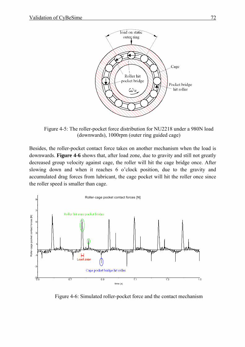
Validation of CyBeSime 72
Figure 4-5: The roller-pocket force distribution for NU2218 under a 980N load (downwards), 1000rpm (outer ring guided cage)
Besides, the roller-pocket contact force takes on another mechanism when the load is downwards. Figure 4-6 shows that, after load zone, due to gravity and still not greatly decreased group velocity against cage, the roller will hit the cage bridge once. After slowing down and when it reaches 6 o’clock position, due to the gravity and accumulated drag forces from lubricant, the cage pocket will hit the roller once since the roller speed is smaller than cage.
Figure 4-6: Simulated roller-pocket force and the contact mechanism
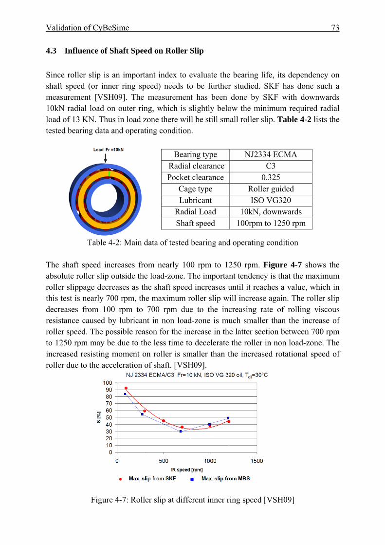
Validation of CyBeSime 73
4.3 Influence of Shaft Speed on Roller Slip Since roller slip is an important index to evaluate the bearing life, its dependency on shaft speed (or inner ring speed) needs to be further studied. SKF has done such a measurement [VSH09]. The measurement has been done by SKF with downwards 10kN radial load on outer ring, which is slightly below the minimum required radial load of 13 KN. Thus in load zone there will be still small roller slip. Table 4-2 lists the tested bearing data and operating condition.
Table 4-2: Main data of tested bearing and operating condition
The shaft speed increases from nearly 100 rpm to 1250 rpm. Figure 4-7 shows the absolute roller slip outside the load-zone. The important tendency is that the maximum roller slippage decreases as the shaft speed increases until it reaches a value, which in this test is nearly 700 rpm, the maximum roller slip will increase again. The roller slip decreases from 100 rpm to 700 rpm due to the increasing rate of rolling viscous resistance caused by lubricant in non load-zone is much smaller than the increase of roller speed. The possible reason for the increase in the latter section between 700 rpm to 1250 rpm may be due to the less time to decelerate the roller in non load-zone. The increased resisting moment on roller is smaller than the increased rotational speed of roller due to the acceleration of shaft. [VSH09].
Figure 4-7: Roller slip at different inner ring speed [VSH09]
Bearing type NJ2334 ECMA Radial clearance C3 Pocket clearance 0.325
Cage type Roller guided Lubricant ISO VG320
Radial Load 10kN, downwards Shaft speed 100rpm to 1250 rpm

Validation of CyBeSime 74
4.4 Bearing Behavior under Excitation In many applications such as railway bearings and car wheel bearings bear often horizontal excitation or impacts. How the roller and cage perform is an important issue. Figure 4-8 is a brief schematic of a test-rig for reproducing the 30Hz excitation with a magnitude from 0.106 mm to 1.061 mm on housing. This results in an increasing velocity when the housing passes the initial position (or middle point of path) from 20mm/s to 200mm/s. Table 4-3 lists the tested bearing data.
Figure 4-8: Schematic of the test-rig Table 4-3 Bearing data and operating condition
Figure 4-9: Detailed loading on the outer ring and its connection with housing (From S. John, IME, RWTH Aachen University)
Tested bearing NU220ECP Radial load 1200N Radial clearance 0.064mm Cage type PA66, roller guidance Shaft speed 1000rpm Oil FVA 3 Shaft speed 1000rpm

Validation of CyBeSime 75
Figure 4-9 shows us the detailed test-rig that constitutes of two ball bearings serving as supporting bearings and the load is downwards on the outer ring. The housing is exerted with a sinuous horizontal excitation which ranges from 0.106mm to 1.061mm in magnitude.
Figure 4-10: Simulated roller slip vs. magnitude of horizontal excitation
Figure 4-10 shows the measured roller slip vs. magnitude of horizontal excitation. The roller slip is increasing from 5% to nearly 15% percent as the shaking magnitudes increases. Another feature is that in load-zone there is no gross slip (not shown in Figure 4-10). Additionally, Figure 4-10 also shows the tendency that, when the shaking magnitude is larger than 0.531mm, the roller slip increases greatly. The maximum slip during one cycle of rotation is nearly proportional to the changing rate of shaking magnitude Ds. Figure 4-11 shows the roller slip of the selected three magnitudes which are 0.265mm, 0.796mm and 1.061mm. The roller slip is plotted versus the azimuth angle. We can see that in all the three cases the roller slip (or dimensionless roller speed) distribution vs. azimuth angle are close to the measurements that done in IME.
Ds=0.265mm, Measurement Ds=0.265mm, Simulation
0°
30°
60°
90°
120°
150°
180°
210°
240°
270°
300°
330°
0°40.0 60.0 80.0 100.0 120.0
[%]
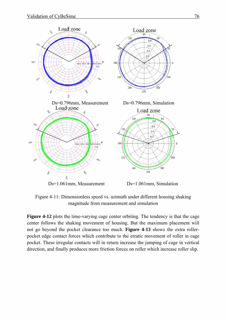
Validation of CyBeSime 76
Ds=0.796mm, Measurement Ds=0.796mm, Simulation
Ds=1.061mm, Measurement Ds=1.061mm, Simulation
Figure 4-11: Dimensionless speed vs. azimuth under different housing shaking
magnitude from measurement and simulation
Figure 4-12 plots the time-varying cage center orbiting. The tendency is that the cage center follows the shaking movement of housing. But the maximum placement will not go beyond the pocket clearance too much. Figure 4-13 shows the extra roller-pocket edge contact forces which contribute to the erratic movement of roller in cage pocket. These irregular contacts will in return increase the jumping of cage in vertical direction, and finally produces more friction forces on roller which increase roller slip.
0°
30°
60°
90°
120°
150°
180°
210°
240°
270 °
300°
330°
0°40.0 60.0 80.0 100.0 120.0
[%]
0°
30°
60°
90°
120°
150°
180°
210°
240°
270°
300°
330°
0°40.0 60.0 80.0 100.0 120.0
[%]
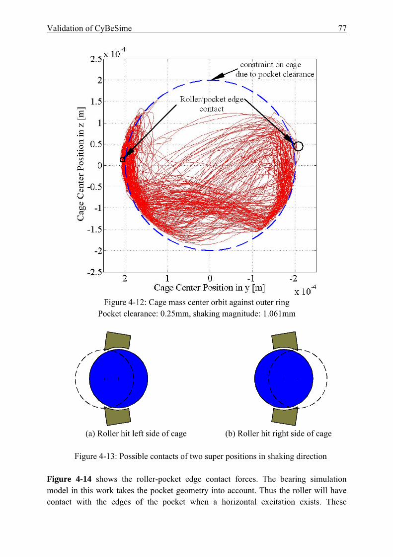
Validation of CyBeSime 77
Figure 4-12: Cage mass center orbit against outer ring
Pocket clearance: 0.25mm, shaking magnitude: 1.061mm
(a) Roller hit left side of cage (b) Roller hit right side of cage
Figure 4-13: Possible contacts of two super positions in shaking direction
Figure 4-14 shows the roller-pocket edge contact forces. The bearing simulation model in this work takes the pocket geometry into account. Thus the roller will have contact with the edges of the pocket when a horizontal excitation exists. These
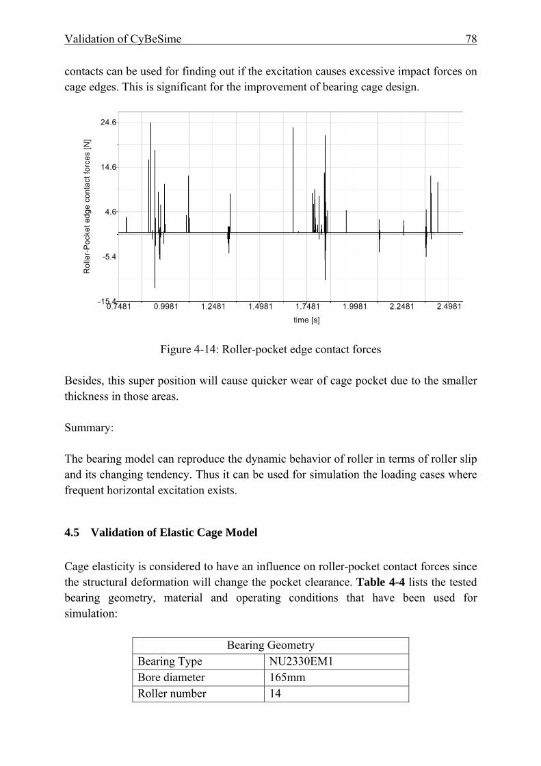
Validation of CyBeSime 78
contacts can be used for finding out if the excitation causes excessive impact forces on cage edges. This is significant for the improvement of bearing cage design.
Figure 4-14: Roller-pocket edge contact forces Besides, this super position will cause quicker wear of cage pocket due to the smaller thickness in those areas. Summary: The bearing model can reproduce the dynamic behavior of roller in terms of roller slip and its changing tendency. Thus it can be used for simulation the loading cases where frequent horizontal excitation exists.
4.5 Validation of Elastic Cage Model Cage elasticity is considered to have an influence on roller-pocket contact forces since the structural deformation will change the pocket clearance. Table 4-4 lists the tested bearing geometry, material and operating conditions that have been used for simulation:
Bearing Geometry Bearing Type NU2330EM1 Bore diameter 165mm Roller number 14
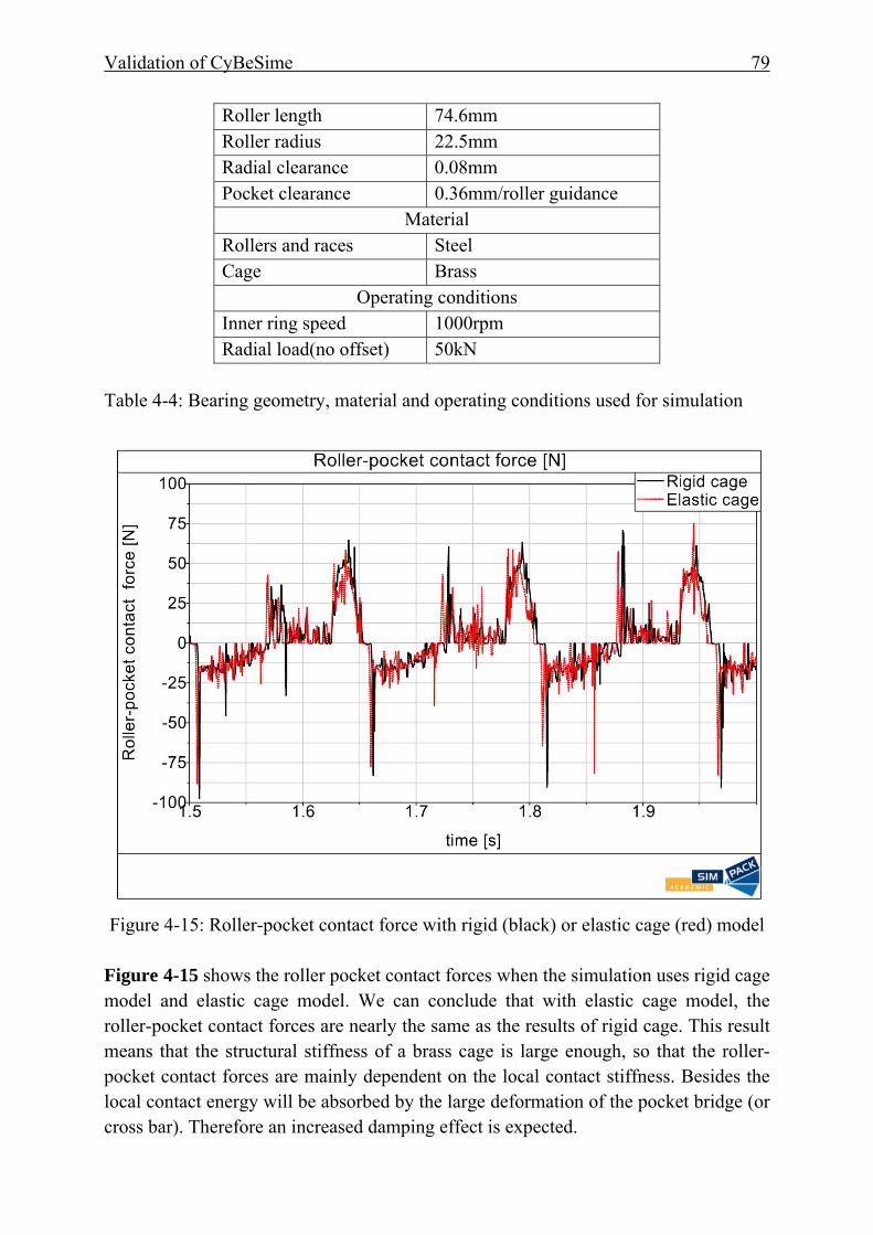
Validation of CyBeSime 79
Roller length 74.6mm Roller radius 22.5mm Radial clearance 0.08mm Pocket clearance 0.36mm/roller guidance
Material Rollers and races Steel Cage Brass
Operating conditions Inner ring speed 1000rpm Radial load(no offset) 50kN
Table 4-4: Bearing geometry, material and operating conditions used for simulation
Figure 4-15: Roller-pocket contact force with rigid (black) or elastic cage (red) model
Figure 4-15 shows the roller pocket contact forces when the simulation uses rigid cage model and elastic cage model. We can conclude that with elastic cage model, the roller-pocket contact forces are nearly the same as the results of rigid cage. This result means that the structural stiffness of a brass cage is large enough, so that the roller-pocket contact forces are mainly dependent on the local contact stiffness. Besides the local contact energy will be absorbed by the large deformation of the pocket bridge (or cross bar). Therefore an increased damping effect is expected.
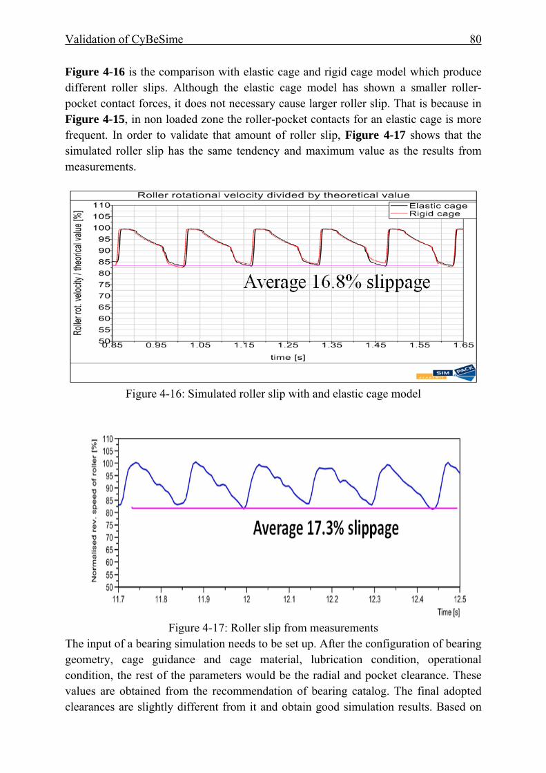
Validation of CyBeSime 80
Figure 4-16 is the comparison with elastic cage and rigid cage model which produce different roller slips. Although the elastic cage model has shown a smaller roller-pocket contact forces, it does not necessary cause larger roller slip. That is because in Figure 4-15, in non loaded zone the roller-pocket contacts for an elastic cage is more frequent. In order to validate that amount of roller slip, Figure 4-17 shows that the simulated roller slip has the same tendency and maximum value as the results from measurements.
Figure 4-16: Simulated roller slip with and elastic cage model
Figure 4-17: Roller slip from measurements
The input of a bearing simulation needs to be set up. After the configuration of bearing geometry, cage guidance and cage material, lubrication condition, operational condition, the rest of the parameters would be the radial and pocket clearance. These values are obtained from the recommendation of bearing catalog. The final adopted clearances are slightly different from it and obtain good simulation results. Based on
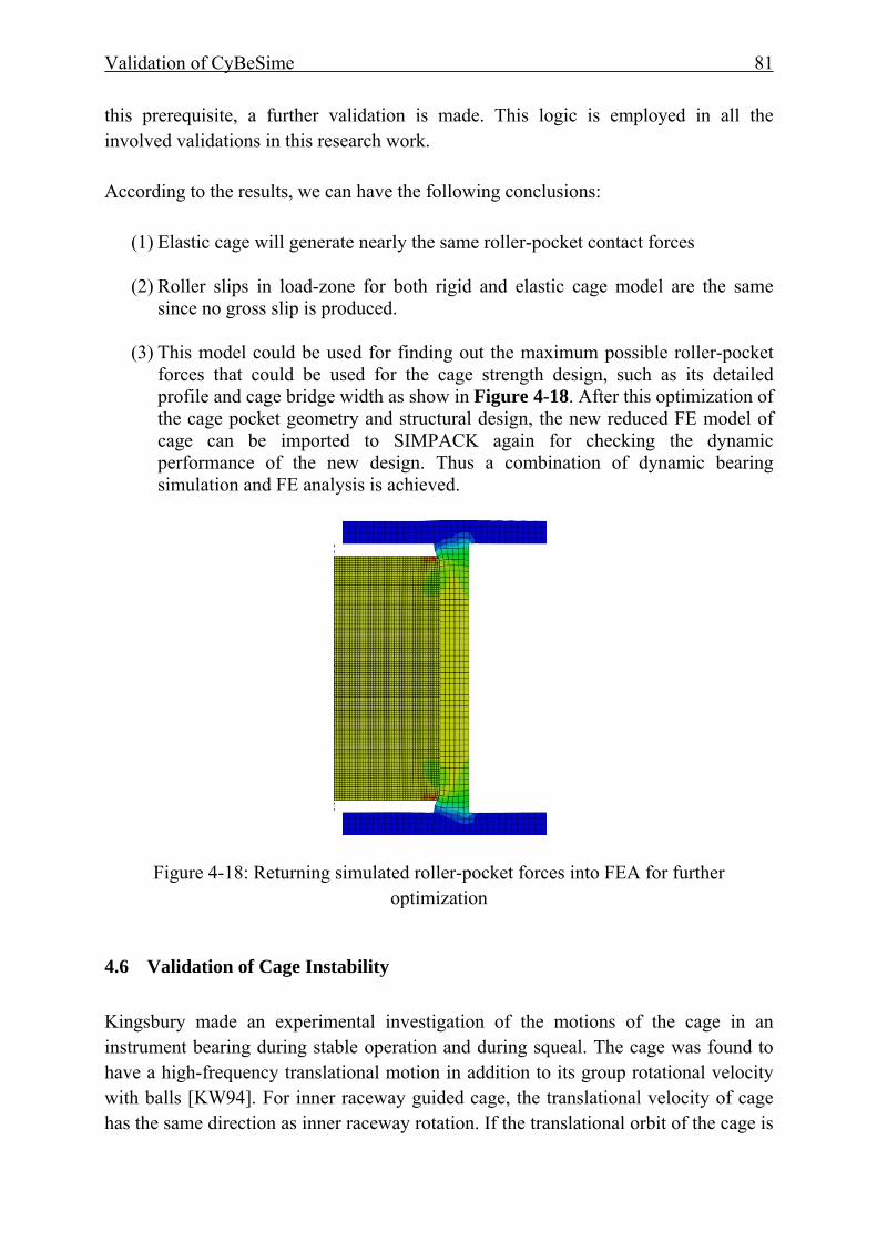
Validation of CyBeSime 81
this prerequisite, a further validation is made. This logic is employed in all the involved validations in this research work.
According to the results, we can have the following conclusions:
(1) Elastic cage will generate nearly the same roller-pocket contact forces
(2) Roller slips in load-zone for both rigid and elastic cage model are the same since no gross slip is produced.
(3) This model could be used for finding out the maximum possible roller-pocket forces that could be used for the cage strength design, such as its detailed profile and cage bridge width as show in Figure 4-18. After this optimization of the cage pocket geometry and structural design, the new reduced FE model of cage can be imported to SIMPACK again for checking the dynamic performance of the new design. Thus a combination of dynamic bearing simulation and FE analysis is achieved.
Figure 4-18: Returning simulated roller-pocket forces into FEA for further optimization
4.6 Validation of Cage Instability Kingsbury made an experimental investigation of the motions of the cage in an instrument bearing during stable operation and during squeal. The cage was found to have a high-frequency translational motion in addition to its group rotational velocity with balls [KW94]. For inner raceway guided cage, the translational velocity of cage has the same direction as inner raceway rotation. If the translational orbit of the cage is
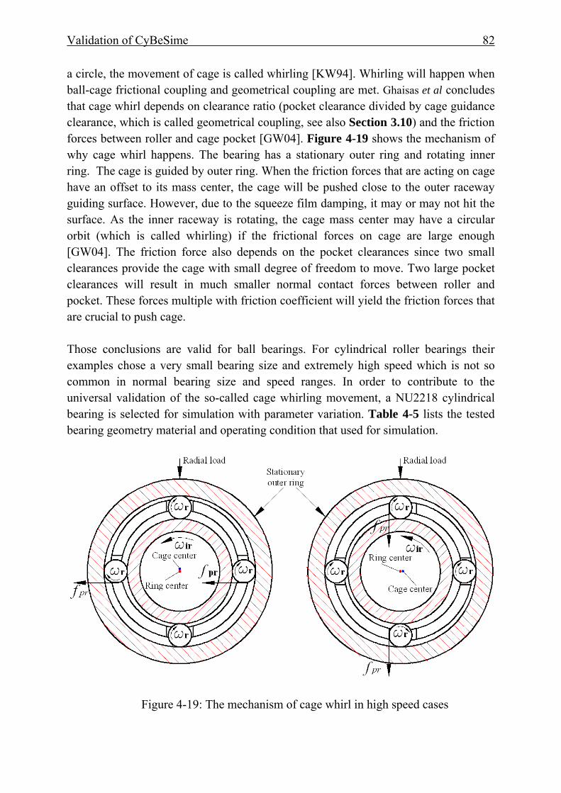
Validation of CyBeSime 82
a circle, the movement of cage is called whirling [KW94]. Whirling will happen when ball-cage frictional coupling and geometrical coupling are met. Ghaisas et al concludes that cage whirl depends on clearance ratio (pocket clearance divided by cage guidance clearance, which is called geometrical coupling, see also Section 3.10) and the friction forces between roller and cage pocket [GW04]. Figure 4-19 shows the mechanism of why cage whirl happens. The bearing has a stationary outer ring and rotating inner ring. The cage is guided by outer ring. When the friction forces that are acting on cage have an offset to its mass center, the cage will be pushed close to the outer raceway guiding surface. However, due to the squeeze film damping, it may or may not hit the surface. As the inner raceway is rotating, the cage mass center may have a circular orbit (which is called whirling) if the frictional forces on cage are large enough [GW04]. The friction force also depends on the pocket clearances since two small clearances provide the cage with small degree of freedom to move. Two large pocket clearances will result in much smaller normal contact forces between roller and pocket. These forces multiple with friction coefficient will yield the friction forces that are crucial to push cage. Those conclusions are valid for ball bearings. For cylindrical roller bearings their examples chose a very small bearing size and extremely high speed which is not so common in normal bearing size and speed ranges. In order to contribute to the universal validation of the so-called cage whirling movement, a NU2218 cylindrical bearing is selected for simulation with parameter variation. Table 4-5 lists the tested bearing geometry material and operating condition that used for simulation.
Figure 4-19: The mechanism of cage whirl in high speed cases

Validation of CyBeSime 83
Bearing Geometry Bearing Type NU2218 Bore diameter 90mm Roller number 17 Roller length 30mm Roller radius 9.5mm Radial clearance 0.04mm Cage landing clearance 0.3mm/outer ring guidance Pocket clearance 0.06 to 0.42mm
Material Rollers Steel Races Steel Cage PA66
Operating conditions Inner ring speed 3000,4300,4600, 5000rpm Radial load 1000,1500,2000,
20kN,40kN,285kN Load offset no
Table 4-5: Bearing geometry, material and operating conditions used for simulation
(a) pgr =1.4 (b) pgr =1.0
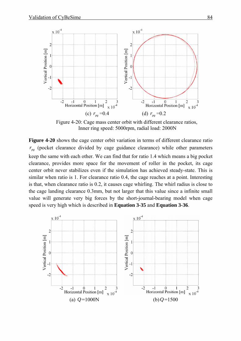
Validation of CyBeSime 84
(c) pgr =0.4 (d) pgr =0.2
Figure 4-20: Cage mass center orbit with different clearance ratios, Inner ring speed: 5000rpm, radial load: 2000N
Figure 4-20 shows the cage center orbit variation in terms of different clearance ratio
pgr (pocket clearance divided by cage guidance clearance) while other parameters keep the same with each other. We can find that for ratio 1.4 which means a big pocket clearance, provides more space for the movement of roller in the pocket, its cage center orbit never stabilizes even if the simulation has achieved steady-state. This is similar when ratio is 1. For clearance ratio 0.4, the cage reaches at a point. Interesting is that, when clearance ratio is 0.2, it causes cage whirling. The whirl radius is close to the cage landing clearance 0.3mm, but not larger that this value since a infinite small value will generate very big forces by the short-journal-bearing model when cage speed is very high which is described in Equation 3-35 and Equation 3-36.
(a) Q =1000N (b)Q =1500
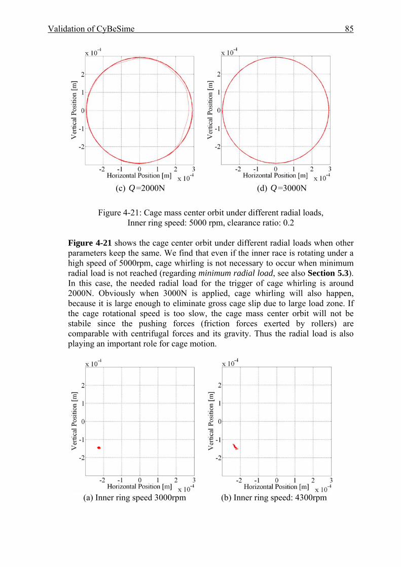
Validation of CyBeSime 85
(c) Q =2000N (d) Q =3000N
Figure 4-21: Cage mass center orbit under different radial loads,
Inner ring speed: 5000 rpm, clearance ratio: 0.2
Figure 4-21 shows the cage center orbit under different radial loads when other parameters keep the same. We find that even if the inner race is rotating under a high speed of 5000rpm, cage whirling is not necessary to occur when minimum radial load is not reached (regarding minimum radial load, see also Section 5.3). In this case, the needed radial load for the trigger of cage whirling is around 2000N. Obviously when 3000N is applied, cage whirling will also happen, because it is large enough to eliminate gross cage slip due to large load zone. If the cage rotational speed is too slow, the cage mass center orbit will not be stabile since the pushing forces (friction forces exerted by rollers) are comparable with centrifugal forces and its gravity. Thus the radial load is also playing an important role for cage motion.
(a) Inner ring speed 3000rpm (b) Inner ring speed: 4300rpm
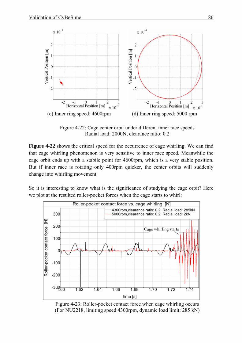
Validation of CyBeSime 86
(c) Inner ring speed: 4600rpm (d) Inner ring speed: 5000 rpm
Figure 4-22: Cage center orbit under different inner race speeds Radial load: 2000N, clearance ratio: 0.2
Figure 4-22 shows the critical speed for the occurrence of cage whirling. We can find that cage whirling phenomenon is very sensitive to inner race speed. Meanwhile the cage orbit ends up with a stabile point for 4600rpm, which is a very stable position. But if inner race is rotating only 400rpm quicker, the center orbits will suddenly change into whirling movement. So it is interesting to know what is the significance of studying the cage orbit? Here we plot at the resulted roller-pocket forces when the cage starts to whirl:
Figure 4-23: Roller-pocket contact force when cage whirling occurs (For NU2218, limiting speed 4300rpm, dynamic load limit: 285 kN)
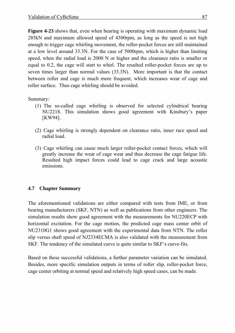
Validation of CyBeSime 87
Figure 4-23 shows that, even when bearing is operating with maximum dynamic load 285kN and maximum allowed speed of 4300rpm, as long as the speed is not high enough to trigger cage whirling movement, the roller-pocket forces are still maintained at a low level around 33.3N. For the case of 5000rpm, which is higher than limiting speed, when the radial load is 2000 N or higher and the clearance ratio is smaller or equal to 0.2, the cage will start to whirl. The resulted roller-pocket forces are up to seven times larger than normal values (33.3N). More important is that the contact between roller and cage is much more frequent, which increases wear of cage and roller surface. Thus cage whirling should be avoided. Summary:
(1) The so-called cage whirling is observed for selected cylindrical bearing NU2218. This simulation shows good agreement with Kinsbury’s paper [KW94].
(2) Cage whirling is strongly dependent on clearance ratio, inner race speed and
radial load.
(3) Cage whirling can cause much larger roller-pocket contact forces, which will greatly increase the wear of cage wear and thus decrease the cage fatigue life. Resulted high impact forces could lead to cage crack and large acoustic emissions.
4.7 Chapter Summary The aforementioned validations are either compared with tests from IME, or from bearing manufacturers (SKF, NTN) as well as publications from other engineers. The simulation results show good agreement with the measurements for NU220ECP with horizontal excitation. For the cage motion, the predicted cage mass center orbit of NU2310G1 shows good agreement with the experimental data from NTN. The roller slip versus shaft speed of NJ2334ECMA is also validated with the measurement from SKF. The tendency of the simulated curve is quite similar to SKF‘s curve-fits. Based on these successful validations, a further parameter variation can be simulated. Besides, more specific simulation outputs in terms of roller slip, roller-pocket force, cage center orbiting at normal speed and relatively high speed cases, can be made.
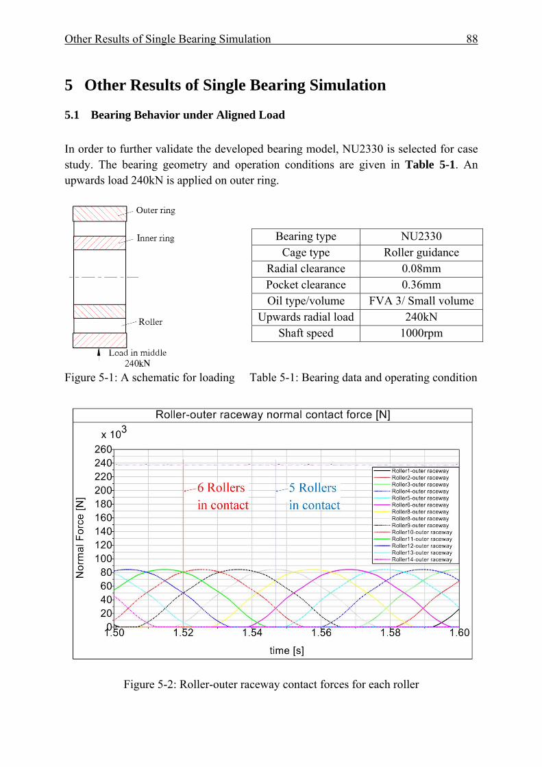
Other Results of Single Bearing Simulation 88
5 Other Results of Single Bearing Simulation
5.1 Bearing Behavior under Aligned Load In order to further validate the developed bearing model, NU2330 is selected for case study. The bearing geometry and operation conditions are given in Table 5-1. An upwards load 240kN is applied on outer ring.
Figure 5-1: A schematic for loading Table 5-1: Bearing data and operating condition
Figure 5-2: Roller-outer raceway contact forces for each roller
Bearing type NU2330 Cage type Roller guidance
Radial clearance 0.08mm Pocket clearance 0.36mm Oil type/volume FVA 3/ Small volume
Upwards radial load 240kN Shaft speed 1000rpm
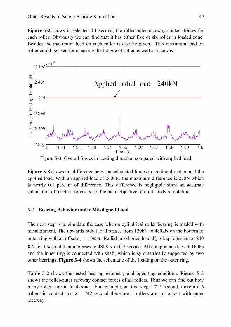
Other Results of Single Bearing Simulation 89
Figure 5-2 shows in selected 0.1 second, the roller-outer raceway contact forces for each roller. Obviously we can find that it has either five or six roller in loaded zone. Besides the maximum load on each roller is also be given. This maximum load on roller could be used for checking the fatigue of roller as well as raceway.
Figure 5-3: Overall forces in loading direction compared with applied load
Figure 5-3 shows the difference between calculated forces in loading direction and the applied load. With an applied load of 240kN, the maximum difference is 270N which is nearly 0.1 percent of difference. This difference is negligible since an accurate calculation of reaction forces is not the main objective of multi-body-simulation.
5.2 Bearing Behavior under Misaligned Load
The next step is to simulate the case when a cylindrical roller bearing is loaded with misalignment. The upwards radial load ranges from 120kN to 480kN on the bottom of outer ring with an offset mmbm 10= . Radial misaligned load mF is kept constant at 240 KN for 1 second then increases to 480KN in 0.2 second. All components have 6 DOFs and the inner ring is connected with shaft, which is symmetrically supported by two other bearings. Figure 5-4 shows the schematic of the loading on the outer ring. Table 5-2 shows the tested bearing geometry and operating condition. Figure 5-5 shows the roller-outer raceway contact forces of all rollers. Thus we can find out how many rollers are in load-zone. For example, at time step 1.715 second, there are 6 rollers in contact and at 1.742 second there are 5 rollers are in contact with outer raceway.
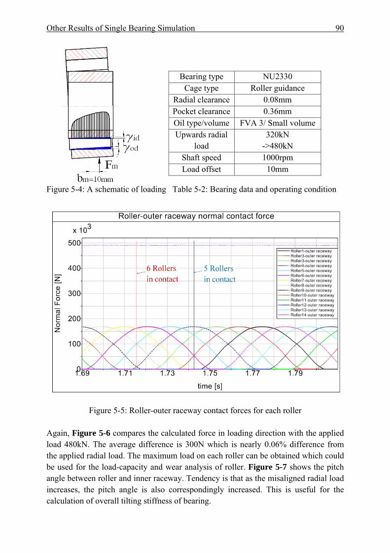
Other Results of Single Bearing Simulation 90
Figure 5-4: A schematic of loading Table 5-2: Bearing data and operating condition
Figure 5-5: Roller-outer raceway contact forces for each roller
Again, Figure 5-6 compares the calculated force in loading direction with the applied load 480kN. The average difference is 300N which is nearly 0.06% difference from the applied radial load. The maximum load on each roller can be obtained which could be used for the load-capacity and wear analysis of roller. Figure 5-7 shows the pitch angle between roller and inner raceway. Tendency is that as the misaligned radial load increases, the pitch angle is also correspondingly increased. This is useful for the calculation of overall tilting stiffness of bearing.
Bearing type NU2330 Cage type Roller guidance
Radial clearance 0.08mm Pocket clearance 0.36mm Oil type/volume FVA 3/ Small volume Upwards radial
load 320kN
->480kN Shaft speed 1000rpm Load offset 10mm
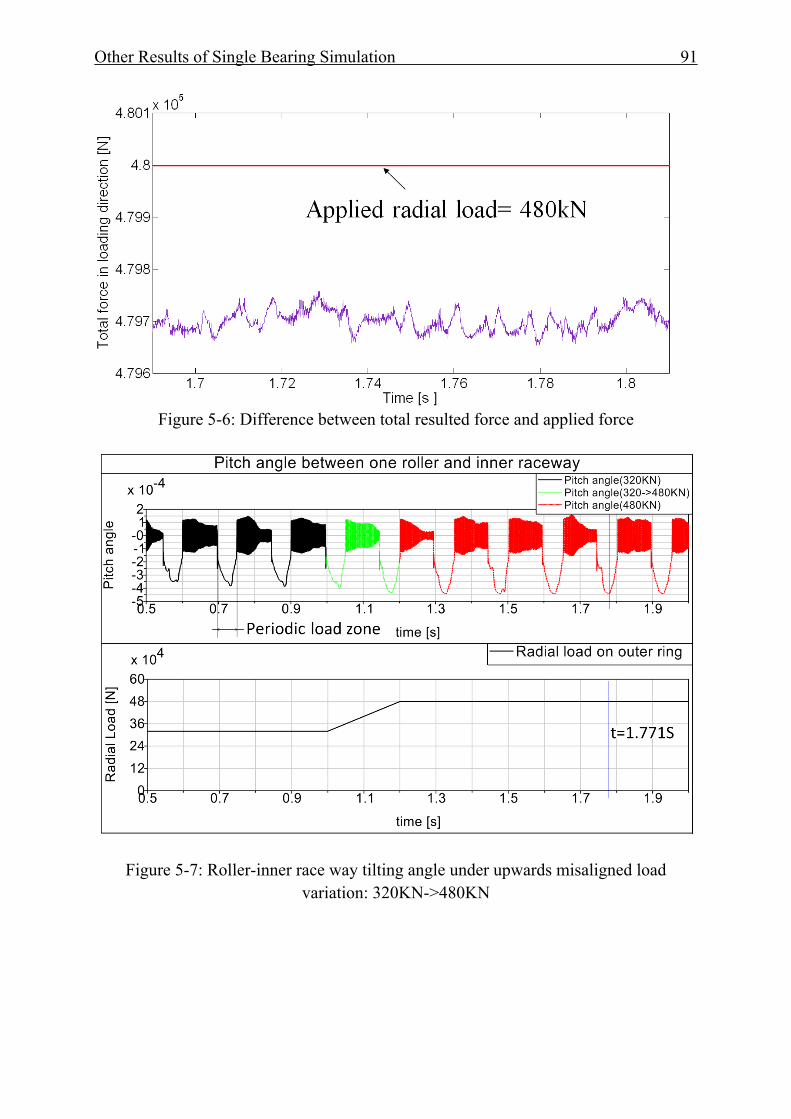
Other Results of Single Bearing Simulation 91
Figure 5-6: Difference between total resulted force and applied force
Figure 5-7: Roller-inner race way tilting angle under upwards misaligned load variation: 320KN->480KN
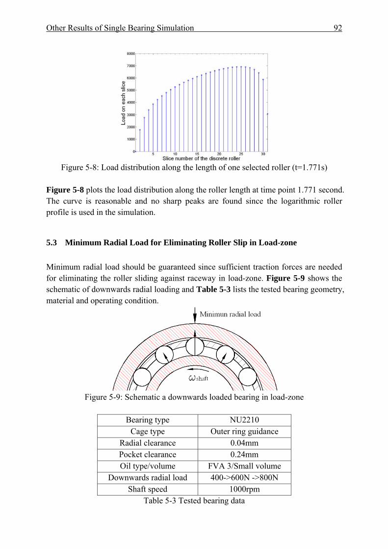
Other Results of Single Bearing Simulation 92
Figure 5-8: Load distribution along the length of one selected roller (t=1.771s)
Figure 5-8 plots the load distribution along the roller length at time point 1.771 second. The curve is reasonable and no sharp peaks are found since the logarithmic roller profile is used in the simulation.
5.3 Minimum Radial Load for Eliminating Roller Slip in Load-zone Minimum radial load should be guaranteed since sufficient traction forces are needed for eliminating the roller sliding against raceway in load-zone. Figure 5-9 shows the schematic of downwards radial loading and Table 5-3 lists the tested bearing geometry, material and operating condition.
Figure 5-9: Schematic a downwards loaded bearing in load-zone
Bearing type NU2210
Cage type Outer ring guidance Radial clearance 0.04mm Pocket clearance 0.24mm Oil type/volume FVA 3/Small volume
Downwards radial load 400->600N ->800N Shaft speed 1000rpm
Table 5-3 Tested bearing data
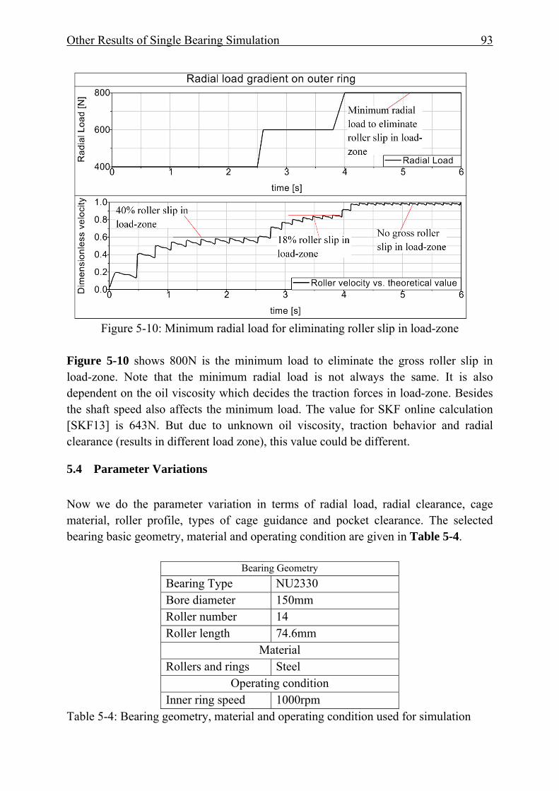
Other Results of Single Bearing Simulation 93
Figure 5-10: Minimum radial load for eliminating roller slip in load-zone
Figure 5-10 shows 800N is the minimum load to eliminate the gross roller slip in load-zone. Note that the minimum radial load is not always the same. It is also dependent on the oil viscosity which decides the traction forces in load-zone. Besides the shaft speed also affects the minimum load. The value for SKF online calculation [SKF13] is 643N. But due to unknown oil viscosity, traction behavior and radial clearance (results in different load zone), this value could be different.
5.4 Parameter Variations Now we do the parameter variation in terms of radial load, radial clearance, cage material, roller profile, types of cage guidance and pocket clearance. The selected bearing basic geometry, material and operating condition are given in Table 5-4.
Bearing Geometry Bearing Type NU2330 Bore diameter 150mm Roller number 14 Roller length 74.6mm
Material Rollers and rings Steel
Operating condition Inner ring speed 1000rpm
Table 5-4: Bearing geometry, material and operating condition used for simulation
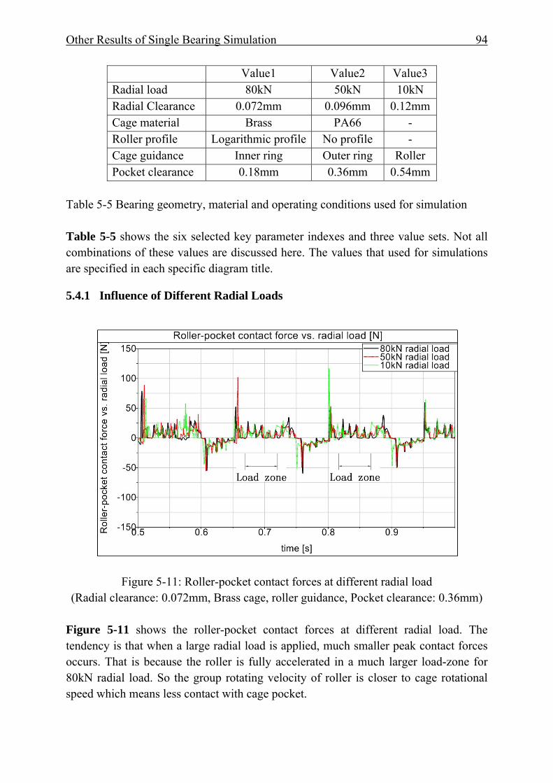
Other Results of Single Bearing Simulation 94
Value1 Value2 Value3 Radial load 80kN 50kN 10kN Radial Clearance 0.072mm 0.096mm 0.12mm Cage material Brass PA66 - Roller profile Logarithmic profile No profile - Cage guidance Inner ring Outer ring Roller Pocket clearance 0.18mm 0.36mm 0.54mm
Table 5-5 Bearing geometry, material and operating conditions used for simulation Table 5-5 shows the six selected key parameter indexes and three value sets. Not all combinations of these values are discussed here. The values that used for simulations are specified in each specific diagram title.
5.4.1 Influence of Different Radial Loads
Figure 5-11: Roller-pocket contact forces at different radial load (Radial clearance: 0.072mm, Brass cage, roller guidance, Pocket clearance: 0.36mm)
Figure 5-11 shows the roller-pocket contact forces at different radial load. The tendency is that when a large radial load is applied, much smaller peak contact forces occurs. That is because the roller is fully accelerated in a much larger load-zone for 80kN radial load. So the group rotating velocity of roller is closer to cage rotational speed which means less contact with cage pocket.
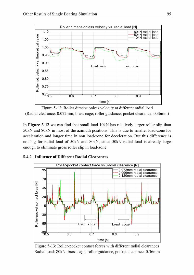
Other Results of Single Bearing Simulation 95
Figure 5-12: Roller dimensionless velocity at different radial load
(Radial clearance: 0.072mm; brass cage; roller guidance; pocket clearance: 0.36mm)
In Figure 5-12 we can find that small load 10kN has relatively larger roller slip than 50kN and 80kN in most of the azimuth positions. This is due to smaller load-zone for acceleration and longer time in non load-zone for deceleration. But this difference is not big for radial load of 50kN and 80kN, since 50kN radial load is already large enough to eliminate gross roller slip in load-zone.
5.4.2 Influence of Different Radial Clearances
Figure 5-13: Roller-pocket contact forces with different radial clearances Radial load: 80kN; brass cage; roller guidance, pocket clearance: 0.36mm
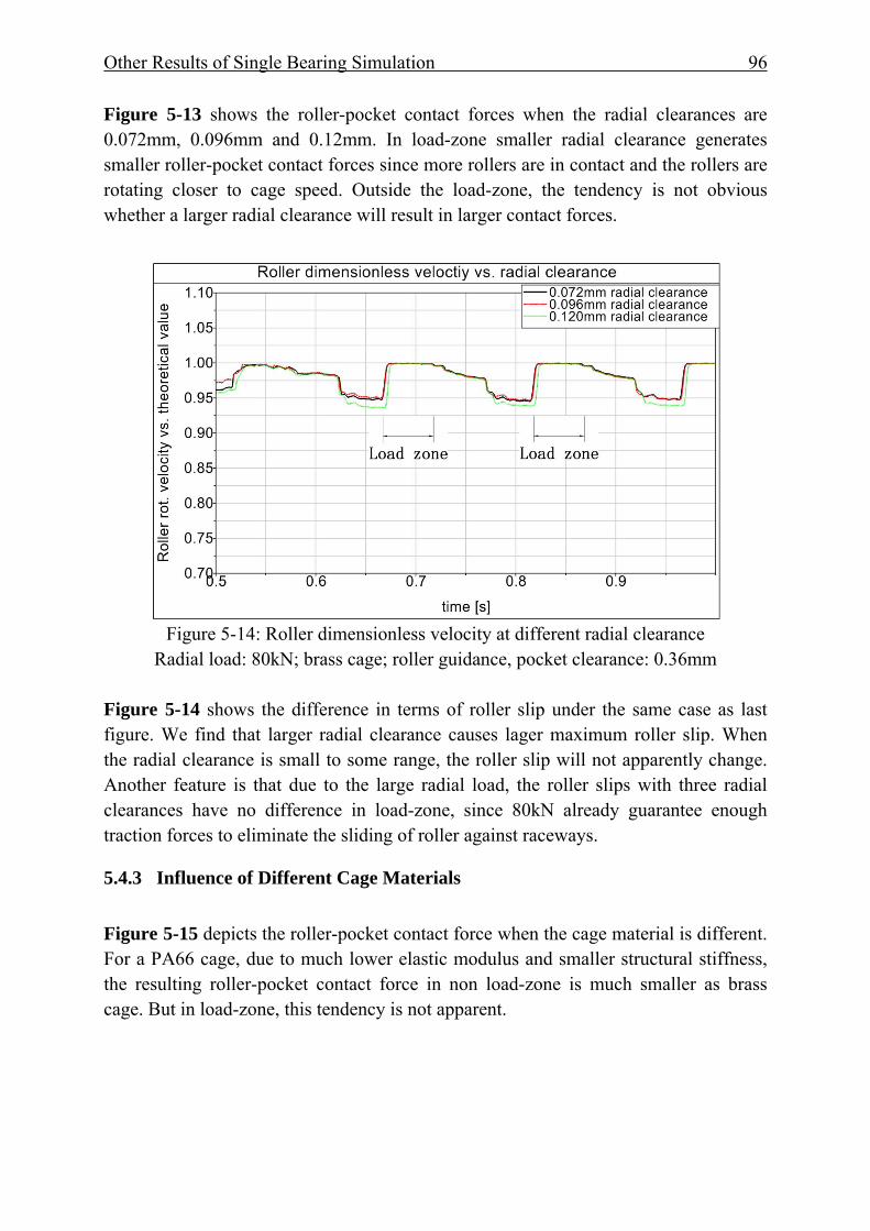
Other Results of Single Bearing Simulation 96
Figure 5-13 shows the roller-pocket contact forces when the radial clearances are 0.072mm, 0.096mm and 0.12mm. In load-zone smaller radial clearance generates smaller roller-pocket contact forces since more rollers are in contact and the rollers are rotating closer to cage speed. Outside the load-zone, the tendency is not obvious whether a larger radial clearance will result in larger contact forces.
Figure 5-14: Roller dimensionless velocity at different radial clearance
Radial load: 80kN; brass cage; roller guidance, pocket clearance: 0.36mm
Figure 5-14 shows the difference in terms of roller slip under the same case as last figure. We find that larger radial clearance causes lager maximum roller slip. When the radial clearance is small to some range, the roller slip will not apparently change. Another feature is that due to the large radial load, the roller slips with three radial clearances have no difference in load-zone, since 80kN already guarantee enough traction forces to eliminate the sliding of roller against raceways.
5.4.3 Influence of Different Cage Materials Figure 5-15 depicts the roller-pocket contact force when the cage material is different. For a PA66 cage, due to much lower elastic modulus and smaller structural stiffness, the resulting roller-pocket contact force in non load-zone is much smaller as brass cage. But in load-zone, this tendency is not apparent.
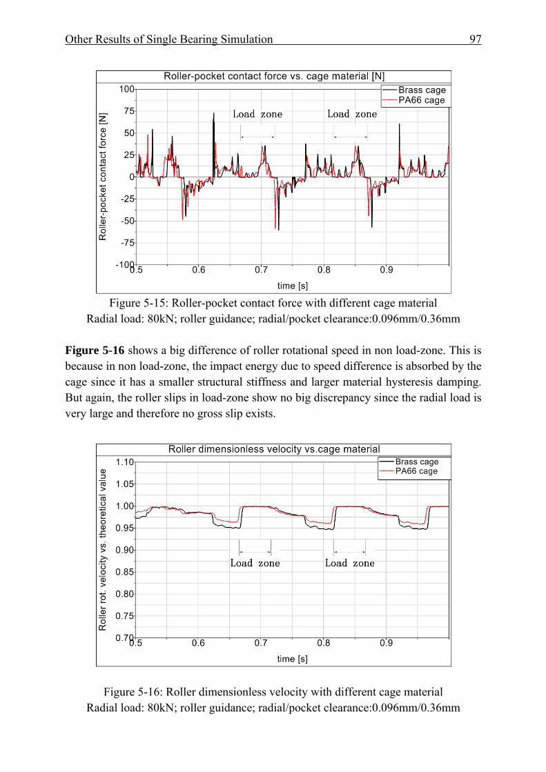
Other Results of Single Bearing Simulation 97
Figure 5-15: Roller-pocket contact force with different cage material
Radial load: 80kN; roller guidance; radial/pocket clearance:0.096mm/0.36mm
Figure 5-16 shows a big difference of roller rotational speed in non load-zone. This is because in non load-zone, the impact energy due to speed difference is absorbed by the cage since it has a smaller structural stiffness and larger material hysteresis damping. But again, the roller slips in load-zone show no big discrepancy since the radial load is very large and therefore no gross slip exists.
Figure 5-16: Roller dimensionless velocity with different cage material Radial load: 80kN; roller guidance; radial/pocket clearance:0.096mm/0.36mm

Other Results of Single Bearing Simulation 98
5.4.4 Influence of Roller Profiles It is also interesting to see the difference of roller profile. As we know that the main purpose of roller profile is to eliminate the pressure concentration near end surfaces and provide some tilting flexibility for shaft. Figure 5-17 shows that roller with logarithmic profile has very small peak contact forces due to the modification of profile in non load-zone. Again, in load-zone, the forces are also slightly smaller than roller without logarithmic profile (cylindrical surface). Thus we can conclude that the modification of roller profile improves not only pressure distribution along roller length, but also reduces the roller-pocket contact forces. The logic can be summarized that a roller with profile has a smaller stiffness, thus there are more rollers in load zone. As a consequence less contact force are exerted on a roller.
Figure 5-17: Roller-pocket contact force with or without logarithmic profile Radial load: 80kN; roller guidance; radial/pocket clearance:0.096mm/0.36mm
In Figure 5-17, the simulated roller–pocket contact forces on a roller when it has a logarithmic profile, are smaller than the rollers without logarithmic profile in non-load-zone. In load-zone, it is more or less the same. It seems that rollers that have profiles are always better a better design than rollers without profile. But too much crown value will decrease the good characteristics of line contact. Furthermore, in non-load-zone, due to logarithmic profile, more space is presented between roller and pocket, which means larger yaw angle will be possible. This may be a drawback.
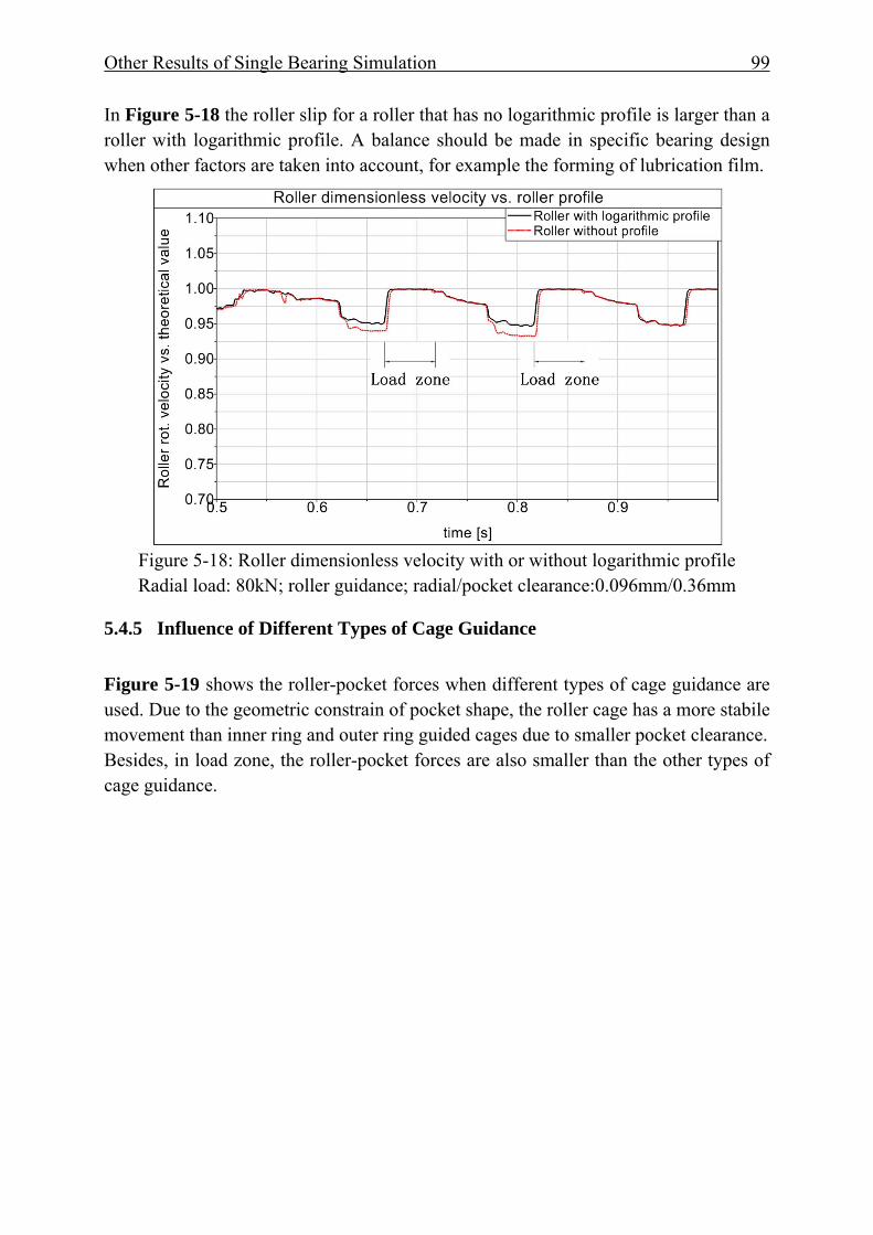
Other Results of Single Bearing Simulation 99
In Figure 5-18 the roller slip for a roller that has no logarithmic profile is larger than a roller with logarithmic profile. A balance should be made in specific bearing design when other factors are taken into account, for example the forming of lubrication film.
Figure 5-18: Roller dimensionless velocity with or without logarithmic profile Radial load: 80kN; roller guidance; radial/pocket clearance:0.096mm/0.36mm
5.4.5 Influence of Different Types of Cage Guidance Figure 5-19 shows the roller-pocket forces when different types of cage guidance are used. Due to the geometric constrain of pocket shape, the roller cage has a more stabile movement than inner ring and outer ring guided cages due to smaller pocket clearance. Besides, in load zone, the roller-pocket forces are also smaller than the other types of cage guidance.
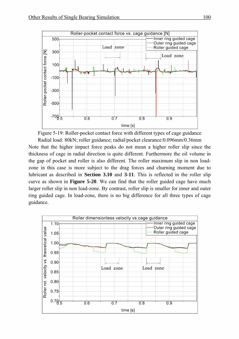
Other Results of Single Bearing Simulation 100
Figure 5-19: Roller-pocket contact force with different types of cage guidance Radial load: 80kN; roller guidance; radial/pocket clearance:0.096mm/0.36mm
Note that the higher impact force peaks do not mean a higher roller slip since the thickness of cage in radial direction is quite different. Furthermore the oil volume in the gap of pocket and roller is also different. The roller maximum slip in non load-zone in this case is more subject to the drag forces and churning moment due to lubricant as described in Section 3.10 and 3-11. This is reflected in the roller slip curve as shown in Figure 5-20. We can find that the roller guided cage have much larger roller slip in non load-zone. By contrast, roller slip is smaller for inner and outer ring guided cage. In load-zone, there is no big difference for all three types of cage guidance.
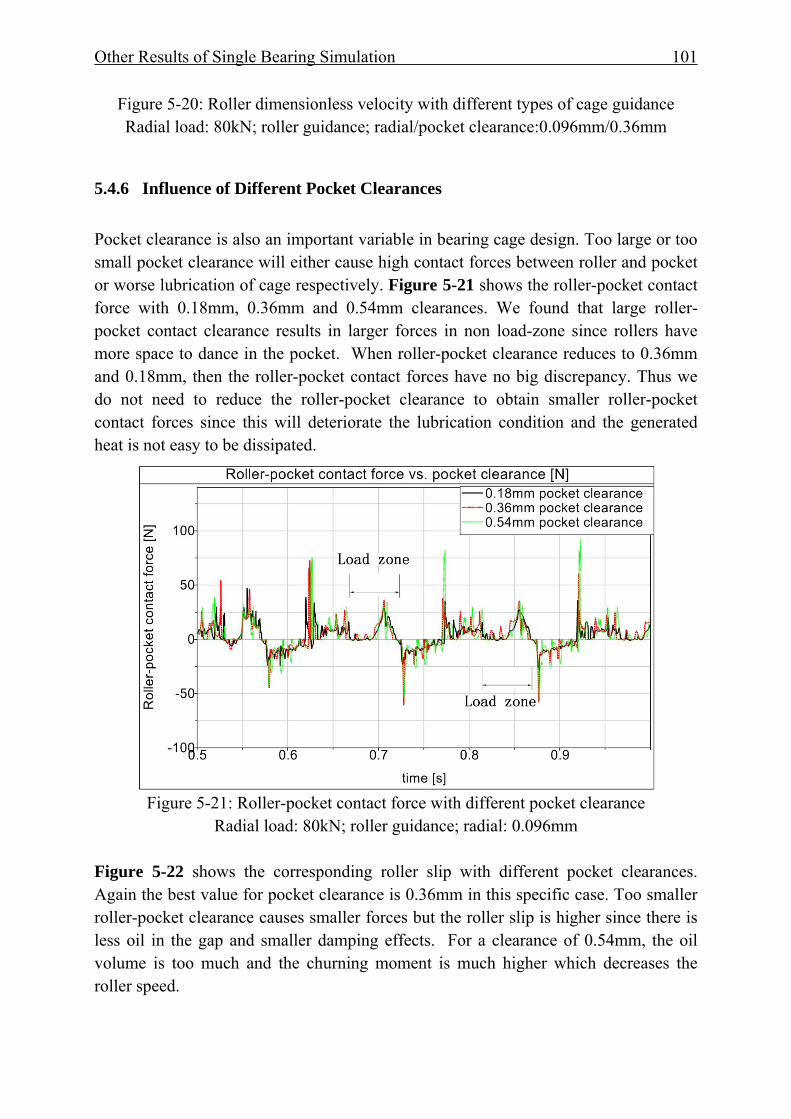
Other Results of Single Bearing Simulation 101
Figure 5-20: Roller dimensionless velocity with different types of cage guidance Radial load: 80kN; roller guidance; radial/pocket clearance:0.096mm/0.36mm
5.4.6 Influence of Different Pocket Clearances Pocket clearance is also an important variable in bearing cage design. Too large or too small pocket clearance will either cause high contact forces between roller and pocket or worse lubrication of cage respectively. Figure 5-21 shows the roller-pocket contact force with 0.18mm, 0.36mm and 0.54mm clearances. We found that large roller-pocket contact clearance results in larger forces in non load-zone since rollers have more space to dance in the pocket. When roller-pocket clearance reduces to 0.36mm and 0.18mm, then the roller-pocket contact forces have no big discrepancy. Thus we do not need to reduce the roller-pocket clearance to obtain smaller roller-pocket contact forces since this will deteriorate the lubrication condition and the generated heat is not easy to be dissipated.
Figure 5-21: Roller-pocket contact force with different pocket clearance
Radial load: 80kN; roller guidance; radial: 0.096mm
Figure 5-22 shows the corresponding roller slip with different pocket clearances. Again the best value for pocket clearance is 0.36mm in this specific case. Too smaller roller-pocket clearance causes smaller forces but the roller slip is higher since there is less oil in the gap and smaller damping effects. For a clearance of 0.54mm, the oil volume is too much and the churning moment is much higher which decreases the roller speed.

Other Results of Single Bearing Simulation 102
Figure 5-22: Roller dimensionless velocity with different pocket clearance
Radial load: 80kN; roller guidance; radial: 0.096mm
5.5 Chapter Summary In this chapter, the cylindrical roller bearing NU2330 is selected for further investigation of the bearing simulation model. The resulting normal contact forces between roller and raceway, the pitch angles under different radial load and the load distribution in a time point is given. CyBeSime can successfully predict the minimum radial load when the type of cylindrical bearing and operational conditions are specified. When misaligning load is applied, the resulting pitch and yaw angle between rollers and raceways can also be predicted. This is useful for the bearing design in the drive lines when the tilting loads are present. Then the parameter variation in terms of radial load, radial clearance, cage material, roller profile, types of cage guidance and pocket clearance is executed to find out the sensitive and critical parameters that influence the roller-pocket forces and roller slip. Regarding to roller slip, the radial load should be the most important factor. Followed by that, cage guidance also greatly influence the roller slip. For inner ring and outer ring guided cages, their maximum roller slips are much smaller than roller guided cages. Different radial clearances also produce different roller slips. Larger clearances result in larger roller slip due to smaller load-zone and less acceleration time. Cage material also affects the maximum slip of roller. In this study a cage made of PA66 presents much smaller roller slip than a cage made of brass. Furthermore when the rollers of a bearing are logarithmically profiled, its maximum slip is smaller than
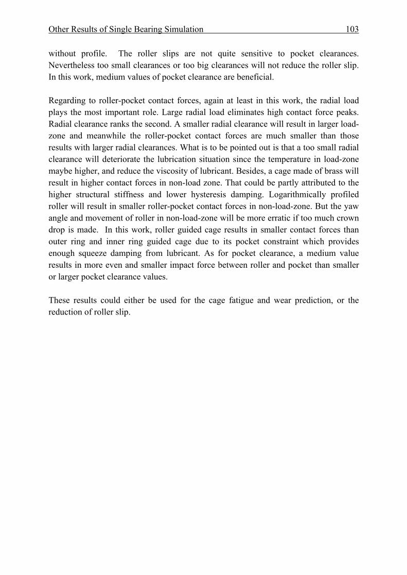
Other Results of Single Bearing Simulation 103
without profile. The roller slips are not quite sensitive to pocket clearances. Nevertheless too small clearances or too big clearances will not reduce the roller slip. In this work, medium values of pocket clearance are beneficial. Regarding to roller-pocket contact forces, again at least in this work, the radial load plays the most important role. Large radial load eliminates high contact force peaks. Radial clearance ranks the second. A smaller radial clearance will result in larger load-zone and meanwhile the roller-pocket contact forces are much smaller than those results with larger radial clearances. What is to be pointed out is that a too small radial clearance will deteriorate the lubrication situation since the temperature in load-zone maybe higher, and reduce the viscosity of lubricant. Besides, a cage made of brass will result in higher contact forces in non-load zone. That could be partly attributed to the higher structural stiffness and lower hysteresis damping. Logarithmically profiled roller will result in smaller roller-pocket contact forces in non-load-zone. But the yaw angle and movement of roller in non-load-zone will be more erratic if too much crown drop is made. In this work, roller guided cage results in smaller contact forces than outer ring and inner ring guided cage due to its pocket constraint which provides enough squeeze damping from lubricant. As for pocket clearance, a medium value results in more even and smaller impact force between roller and pocket than smaller or larger pocket clearance values. These results could either be used for the cage fatigue and wear prediction, or the reduction of roller slip.
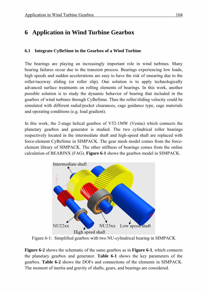
Application in Wind Turbine Gearbox 104
6 Application in Wind Turbine Gearbox
6.1 Integrate CyBeSime in the Gearbox of a Wind Turbine The bearings are playing an increasingly important role in wind turbines. Many bearing failures occur due to the transient process. Bearings experiencing low loads, high speeds and sudden accelerations are easy to have the risk of smearing due to the roller/raceway sliding (or roller slip). One solution is to apply technologically advanced surface treatments on rolling elements of bearings. In this work, another possible solution is to study the dynamic behavior of bearing that included in the gearbox of wind turbines through CyBeSime. Thus the roller/sliding velocity could be simulated with different radial/pocket clearances, cage guidance type, cage materials and operating conditions (e.g. load gradient). In this work, the 2-stage helical gearbox of V52-1MW (Vestas) which connects the planetary gearbox and generator is studied. The two cylindrical roller bearings respectively located in the intermediate shaft and high-speed shaft are replaced with force-element CyBeSime in SIMPACK. The gear mesh model comes from the force-element library of SIMPACK. The other stiffness of bearings comes from the online calculation of BEARINX (FAG). Figure 6-1 shows the gearbox model in SIMPACK.
Figure 6-1: Simplified gearbox with two NU-cylindrical bearing in SIMPACK
Figure 6-2 shows the schematic of the same gearbox as in Figure 6-1, which connects the planetary gearbox and generator. Table 6-1 shows the key parameters of the gearbox. Table 6-2 shows the DOFs and connections of the elements in SIMPACK. The moment of inertia and gravity of shafts, gears, and bearings are considered.
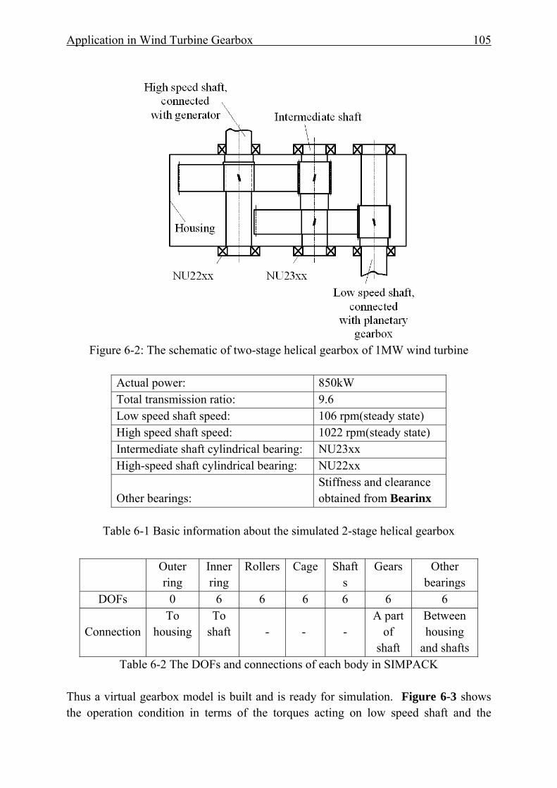
Application in Wind Turbine Gearbox 105
Figure 6-2: The schematic of two-stage helical gearbox of 1MW wind turbine
Actual power: 850kW Total transmission ratio: 9.6 Low speed shaft speed: 106 rpm(steady state) High speed shaft speed: 1022 rpm(steady state) Intermediate shaft cylindrical bearing: NU23xx High-speed shaft cylindrical bearing: NU22xx Other bearings:
Stiffness and clearance obtained from Bearinx
Table 6-1 Basic information about the simulated 2-stage helical gearbox
Table 6-2 The DOFs and connections of each body in SIMPACK
Thus a virtual gearbox model is built and is ready for simulation. Figure 6-3 shows the operation condition in terms of the torques acting on low speed shaft and the
Outer ring
Inner ring
Rollers Cage Shafts
Gears Other bearings
DOFs 0 6 6 6 6 6 6
Connection To
housing To
shaft -
-
-
A part of
shaft
Between housing
and shafts
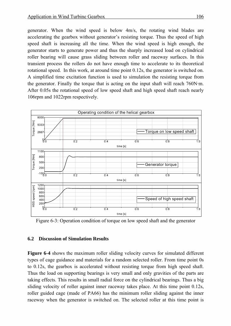
Application in Wind Turbine Gearbox 106
generator. When the wind speed is below 4m/s, the rotating wind blades are accelerating the gearbox without generator’s resisting torque. Thus the speed of high speed shaft is increasing all the time. When the wind speed is high enough, the generator starts to generate power and thus the sharply increased load on cylindrical roller bearing will cause grass sliding between roller and raceway surfaces. In this transient process the rollers do not have enough time to accelerate to its theoretical rotational speed. In this work, at around time point 0.12s, the generator is switched on. A simplified time excitation function is used to simulation the resisting torque from the generator. Finally the torque that is acting on the input shaft will reach 760N·m. After 0.05s the rotational speed of low speed shaft and high speed shaft reach nearly 106rpm and 1022rpm respectively.
Figure 6-3: Operation condition of torque on low speed shaft and the generator
6.2 Discussion of Simulation Results Figure 6-4 shows the maximum roller sliding velocity curves for simulated different types of cage guidance and materials for a random selected roller. From time point 0s to 0.12s, the gearbox is accelerated without resisting torque from high speed shaft. Thus the load on supporting bearings is very small and only gravities of the parts are taking effects. This results in small radial force on the cylindrical bearings. Thus a big sliding velocity of roller against inner raceway takes place. At this time point 0.12s, roller guided cage (made of PA66) has the minimum roller sliding against the inner raceway when the generator is switched on. The selected roller at this time point is
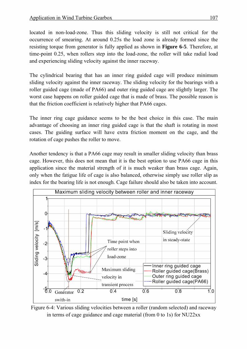
Application in Wind Turbine Gearbox 107
located in non-load-zone. Thus this sliding velocity is still not critical for the occurrence of smearing. At around 0.25s the load zone is already formed since the resisting torque from generator is fully applied as shown in Figure 6-5. Therefore, at time-point 0.25, when rollers step into the load-zone, the roller will take radial load and experiencing sliding velocity against the inner raceway. The cylindrical bearing that has an inner ring guided cage will produce minimum sliding velocity against the inner raceway. The sliding velocity for the bearings with a roller guided cage (made of PA66) and outer ring guided cage are slightly larger. The worst case happens on roller guided cage that is made of brass. The possible reason is that the friction coefficient is relatively higher that PA66 cages. The inner ring cage guidance seems to be the best choice in this case. The main advantage of choosing an inner ring guided cage is that the shaft is rotating in most cases. The guiding surface will have extra friction moment on the cage, and the rotation of cage pushes the roller to move. Another tendency is that a PA66 cage may result in smaller sliding velocity than brass cage. However, this does not mean that it is the best option to use PA66 cage in this application since the material strength of it is much weaker than brass cage. Again, only when the fatigue life of cage is also balanced, otherwise simply use roller slip as index for the bearing life is not enough. Cage failure should also be taken into account.
Figure 6-4: Various sliding velocities between a roller (random selected) and raceway
in terms of cage guidance and cage material (from 0 to 1s) for NU22xx

Application in Wind Turbine Gearbox 108
Figure 6-5: Normal load between a roller and inner raceway in terms of cage guidance
and cage material (from 0 to 1s) for NU22xx Figure 6-6 shows the cage’s horizontal and vertical position from 0s to 2s. Before it reaches the steady state, the cage movement is not stabile since the roller-pocket contact forces are erratic. When its orbit is stabile, the final position of cage mass center will come to a point. Note that not in all operational conditions the cage mass center will be stabilized in one point, it still depends on the radial load, radial clearance and inner ring speed.
Figure 6-6: Cage mass center horizontal and vertical position for NU22xx
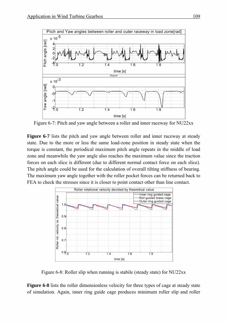
Application in Wind Turbine Gearbox 109
Figure 6-7: Pitch and yaw angle between a roller and inner raceway for NU22xx
Figure 6-7 lists the pitch and yaw angle between roller and inner raceway at steady state. Due to the more or less the same load-zone position in steady state when the torque is constant, the periodical maximum pitch angle repeats in the middle of load zone and meanwhile the yaw angle also reaches the maximum value since the traction forces on each slice is different (due to different normal contact force on each slice). The pitch angle could be used for the calculation of overall tilting stiffness of bearing. The maximum yaw angle together with the roller pocket forces can be returned back to FEA to check the stresses since it is closer to point contact other than line contact.
Figure 6-8: Roller slip when running is stabile (steady state) for NU22xx
Figure 6-8 lists the roller dimensionless velocity for three types of cage at steady state of simulation. Again, inner ring guide cage produces minimum roller slip and roller
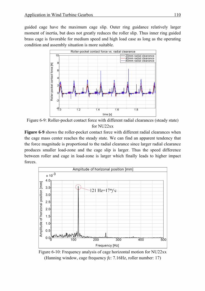
Application in Wind Turbine Gearbox 110
guided cage have the maximum cage slip. Outer ring guidance relatively larger moment of inertia, but does not greatly reduces the roller slip. Thus inner ring guided brass cage is favorable for medium speed and high load case as long as the operating condition and assembly situation is more suitable.
Figure 6-9: Roller-pocket contact force with different radial clearances (steady state)
for NU22xx Figure 6-9 shows the roller-pocket contact force with different radial clearances when the cage mass center reaches the steady state. We can find an apparent tendency that the force magnitude is proportional to the radial clearance since larger radial clearance produces smaller load-zone and the cage slip is larger. Thus the speed difference between roller and cage in load-zone is larger which finally leads to higher impact forces.
Figure 6-10: Frequency analysis of cage horizontal motion for NU22xx
(Hanning window, cage frequency fc: 7.16Hz, roller number: 17)
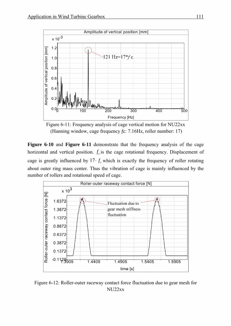
Application in Wind Turbine Gearbox 111
Figure 6-11: Frequency analysis of cage vertical motion for NU22xx
(Hanning window, cage frequency fc: 7.16Hz, roller number: 17)
Figure 6-10 and Figure 6-11 demonstrate that the frequency analysis of the cage horizontal and vertical position. cf is the cage rotational frequency. Displacement of
cage is greatly influenced by cf⋅17 which is exactly the frequency of roller rotating about outer ring mass center. Thus the vibration of cage is mainly influenced by the number of rollers and rotational speed of cage.
Figure 6-12: Roller-outer raceway contact force fluctuation due to gear mesh for NU22xx
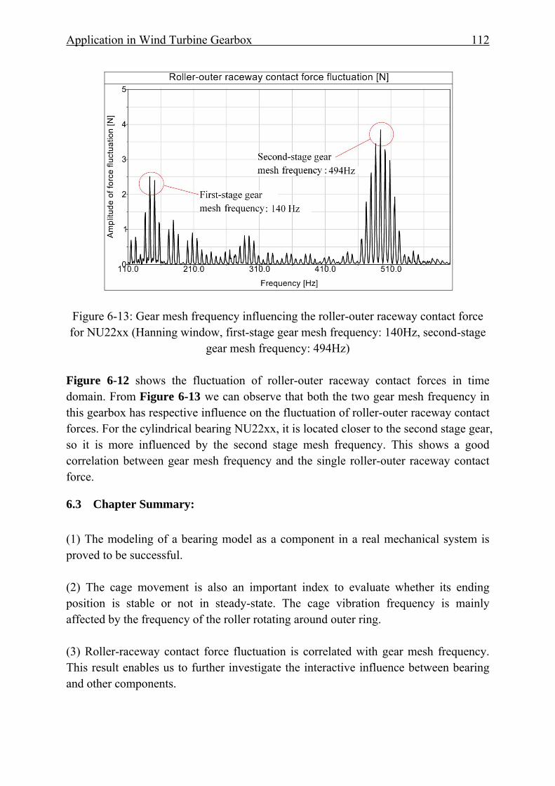
Application in Wind Turbine Gearbox 112
Figure 6-13: Gear mesh frequency influencing the roller-outer raceway contact force for NU22xx (Hanning window, first-stage gear mesh frequency: 140Hz, second-stage
gear mesh frequency: 494Hz) Figure 6-12 shows the fluctuation of roller-outer raceway contact forces in time domain. From Figure 6-13 we can observe that both the two gear mesh frequency in this gearbox has respective influence on the fluctuation of roller-outer raceway contact forces. For the cylindrical bearing NU22xx, it is located closer to the second stage gear, so it is more influenced by the second stage mesh frequency. This shows a good correlation between gear mesh frequency and the single roller-outer raceway contact force.
6.3 Chapter Summary: (1) The modeling of a bearing model as a component in a real mechanical system is proved to be successful. (2) The cage movement is also an important index to evaluate whether its ending position is stable or not in steady-state. The cage vibration frequency is mainly affected by the frequency of the roller rotating around outer ring. (3) Roller-raceway contact force fluctuation is correlated with gear mesh frequency. This result enables us to further investigate the interactive influence between bearing and other components.

Application in Wind Turbine Gearbox 113
(4) The obtained sliding velocity between roller and inner raceway provides us a possibility to analyze and optimize the bearing design parameters and cage type selection as well as the operation condition guidelines and adjustments to avoid the smearing phenomenon of roller and raceway.
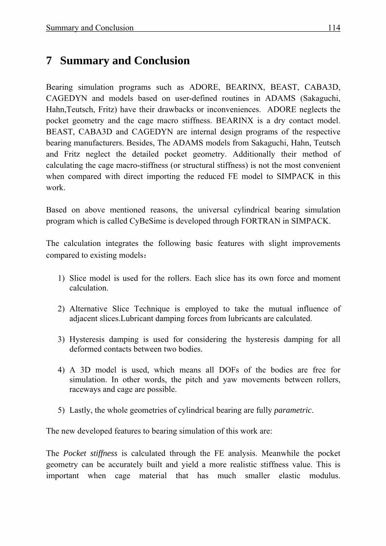
Summary and Conclusion 114
7 Summary and Conclusion Bearing simulation programs such as ADORE, BEARINX, BEAST, CABA3D, CAGEDYN and models based on user-defined routines in ADAMS (Sakaguchi, Hahn,Teutsch, Fritz) have their drawbacks or inconveniences. ADORE neglects the pocket geometry and the cage macro stiffness. BEARINX is a dry contact model. BEAST, CABA3D and CAGEDYN are internal design programs of the respective bearing manufacturers. Besides, The ADAMS models from Sakaguchi, Hahn, Teutsch and Fritz neglect the detailed pocket geometry. Additionally their method of calculating the cage macro-stiffness (or structural stiffness) is not the most convenient when compared with direct importing the reduced FE model to SIMPACK in this work. Based on above mentioned reasons, the universal cylindrical bearing simulation program which is called CyBeSime is developed through FORTRAN in SIMPACK. The calculation integrates the following basic features with slight improvements compared to existing models:
1) Slice model is used for the rollers. Each slice has its own force and moment calculation.
2) Alternative Slice Technique is employed to take the mutual influence of
adjacent slices.Lubricant damping forces from lubricants are calculated.
3) Hysteresis damping is used for considering the hysteresis damping for all deformed contacts between two bodies.
4) A 3D model is used, which means all DOFs of the bodies are free for
simulation. In other words, the pitch and yaw movements between rollers, raceways and cage are possible.
5) Lastly, the whole geometries of cylindrical bearing are fully parametric.
The new developed features to bearing simulation of this work are: The Pocket stiffness is calculated through the FE analysis. Meanwhile the pocket geometry can be accurately built and yield a more realistic stiffness value. This is important when cage material that has much smaller elastic modulus.
Summary and Conclusion 115
The Pocket geometry of roller of a roller guided cage distinguishes the different types of pocket shape, which has an influence on roller-pocket pocket forces and cage motion. The Cage pocket clearance and guiding clearances are introduced for further parameter variations. The optimization of these clearances can be achieved when the objective functions are selected (e.g. minimum roller-pocket forces, minimum roller slip, stabile cage mass center orbit). The Cage macro stiffness is considered by importing the reduced FE model of cage into SIMPACK. Thus most important modal shapes are kept. Finally the method for contact detection, calculating the forces and moments acting on bearing elements during simulation have been validated successfully. The simulation results of CyBeSime show good agreement with measurements from SKF, NTN, internal test of IME, RWTH Aachen University and other publications. The simulation outputs such as the normal force between roller and raceways, roller slip, cage slip, roller-pocket contact forces and its mechanism versus azimuth angle, minimum radial load to eliminate the roller slip in load-zone for a specific cylindrical bearing, the load on each slice of a roller, the load zone angle, cage mass center orbit, the roller-pocket edge contact forces are available. The first case studies show feasible results. Thus the developed bearing simulation program CyBeSime can be used for the investigation of dynamic bearing performance. Possible applications for engineers:
1) Prediction of roller slip of the cylindrical bearings in wind turbine and trains as well as other applications when the roller slip is the main source of bearing damage.
2) Cage pocket shape and geometrical structure optimization in combination with FEA software. A closed design loop can be used for cage design.
3) Cage wear and vibration can be predicted in terms of cage material(brass, steel or PA66), pocket clearance and the types of cage guidance
4) Selection of the radial clearance for a specific bearing arrangement.
5) Integrate the bearing simulation model in complex drive-line to reproduce the interaction with gear mesh even when misalignment of load is present. The tilting angle can be predicted.
6) Extend this program to the dynamic simulation of ball bearings, spherical bearings and tapered roller bearings.

Summary and Conclusion 116
Outlook 117
8 Outlook
The bearing simulation technology is updating with time. All the current developed simulation models are just the possible approximations of the realistic physical models. Thus there is still room to improve CyBeSime. The following aspects are listed to show the drawbacks of this model as well as the outlook of improvements on CyBeSime:
(1) The lubrication model for roller and pocket contact should be investigated with a better approximation, which plays an important role in non load-zone especially when massive oil is used.
(2) The outer ring-housing contact and inner ring-shaft contact should also be
considered since in high load cases the deformation in those two contacts will contribute to the uneven load distribution when the bearing width is small.
(3) The FEA for determining the roller-pocket contact stiffness should be
improved. The approaching velocity between roller and pocket should also be considered.
(4) A sophisticated and explicit viscosity-pressure-temperature relationship should be developed in the future.
(5) Roller-rib contact should take detailed geometry into account.
(6) The oil introduced rolling viscous forces and moments acting on surfaces of bearing elements need to be further investigated.
Literature 118
9 Literature [ADA13] http://www.mscsoftware.com/sites/default/files/inline-
images/suspension_0.gif
[Arc61] Archard, J. F.; Kirk, M. T.: Lubrication at Point Contacts. Proceeding of the Royal Society of London, 261:532-550, 1961
[Arc80] Archard, J. F.: Wear Theory and Mechanism. Wear Control Handbook, ASME New York, 1980
[AS12] Ashtekar, A.; Sadeghi, F.: A New Approach for Including Cage Flexibility in Dynamic Bearing Models by Using Combined Explicit Finite and Discrete Element Methods. ASME Journal of Tribology, 134, 2012
[Baa95] Baalmann, K.: Grundlagen zur Ermittlung des Beiwertes a3 für die Wälzlagerlebensdauer. VDI Berichte Nr. 1207, 1995
[Bal05] Baly, H.: Reibung fettgeschmierter Wälzlager. Doctoral thesis, University of Hannover, 2005
[Bar97] Bartels, T.: Instationäres Gleitwälzkontaktmodell zur Simulation der Reibung und Kinematik von Rollenlagern. Doctoral thesis, Ruhr-Universität Bochum, 1997
[Ber11] Berroth, J.k.: Konstruktion und Modellierung der Strukturbauteile einer Offshore Windenergieanlage für die Mehrkörpersimulation. Diploma thesis, IME, RWTH Aachen Univrsity, 2011
[BG01] Beitz, W.; Grote, K. H.: Dubbel Taschenbuch für den Maschinenbau. 20. Auflage. Springer Verlag, 2001
[Blu87] Blume, J.: Druck- und Temperatureinfluß auf Viskosität und Kompressibilität von flüssigen Schmierstoffen. Doctoral thesis, RWTH Aachen Universtiy, 1987
[Bös78] Böswirth, L.: Zur Berechnung des Quetsch- und Klebeeffektes bei dünnen flüssigkeitsgefüllten Spalten. VDI Berichte Nr. 47, 1978
[Bre94] Breuer, M.: Theoretische und experimentelle Bestimmung der Wälzlagersteifigkeit, Doctoral thesis University of Hannover, 1994
[Cor06] Correns, M.: DIN ISO 281 Beiblatt 4 Lebensdauerberechnung unter Berücksichtigung realer Lastverteilungen und Kontaktspannungen. VDI Berichte, 23-32, 1994(2006)
[CS71] Conry, T.F.; Seireg, A.: Mathematical Programming Method for Design of Elastic Bodies in Contact. Journal of Applied Mechanics, 387-392, 1971
[CWC87] Conry, T. F; Wand, S.; Cusano, C.: A Reynolds-Eyring Equation for Elastohydrodynamic Lubrication in Line Contacts. Transactions of the ASME, Journal of Tribology, 109:648-654, 1987.
[CWD13] http://www.cwd.rwth-aachen.de/

Literature 119
[Deg09] Degtiarev, A.: BEARINXR- SIMPACK: Simulation Processes Are under Control. In: SIMPEP, FVA Kongress zur Simulation im Produktentstehungsprozess Schaeffler KG, 2009
[Die97] Dietl, P.: Damping and Stiffness Characteristics of Rolling Element Bearings. Doctoral thesis, Technical University of Wien, 1997
[DIN281-4] DIN ISO 281: Dynamische Tragzahlen und nominelle Lebensdauer Verfahren zur Berechnung der modifizierten Referenz- Lebensdauer für allgemein belastete Wälzlager, 2003
[DW65] Dowson, D.; Whitaker, A. V.: The isothermal lubrication of Cylinders. In: ASLE transactions: A Publication of the American Society of Lubrication Engineers, 8:24-235, 1965
[DWN00] Dietl, P.; Wensing, J.; van Nijen, G. C.: Rolling bearing damping for dynamic analysis of multi-body systems—experimental and theoretical results. 33-43, 2000
[DH59] Dowson, D.; Higginson, D. R.: A Numerical Solution to the Elastohydrodynamic Problem. Journal of Mechanical Engineering Science, 6-15, 1959
[EHW85] Eschmann, P.; Hasbargen, L.; Weigand, K.: Ball and Roller Bearings. R. Oldenbourg Verlag, 1985, ISBN 0-471-26283-8
[Ert84] Ertel, M. A.: Die Berechnung der hydrodynamischen Schmierung gekrümmter Oberflächen unter hoher Belastung und Relativbewegung. VDI Berichte Nr.115, 1984
[FH41] Föppl, L. ; Huber, K.: Der Gültigkeitsbereich der Elastizitätstheorie. In: Forschung auf dem Gebiete des Ingenieurswesens, Nr. 6, 261-265, 1941
[FK07] Fujiwara, H.; Kawase, T.: Logarithmic Profiles of Rollers in Roller Bearings and Optimization of the Profiles. NTN Technical review, 140-148, 2007
[FSH09] Fritz, F.; Seemann, W.; Hinterkausen, M.: Modellierung von Rollenlagern als Element einer Mehrkörperdynamiksimulation. SIRM 2009, 8th Internationale Tagung Schwingungen in Rotierenden Maschinen, 1-11, 2009
[Fri11] Fritz, F.: Modellierung von Wälzlagern als generische Maschinenelemente einer Mehrkörpersimulation. Doctoral thesis, Karlsruhe Institute of Technology, Germany, 2011
[GC63] Gohar, R.; Cameron, A.: Optical Measurement of Oil Film Thickness under Elasto-hydrodynamic Lubrication. Nature, 200:458-459, 1963.
[Gin08] Ginsberg, J.H.: Engineering Dynamics, 2008, ISBN 978-0-521-88303-0
[Gup84] Gupta, P. K.: Advanced Dynamics of Rolling Elements. Springer-Verlag, 1984 ISBN 3-540-96031-7
[GV49] Grubin AN, A. N.; Vinogradova. I. E.: Investigation of the Contact of Machine Components (in Russian). Book No.30. Central Scientific Research Institute for Technology and Mechanical Engineering, Moscow, 1949
Literature 120
[GWS04] Ghaisas. N.; Wassgren, C. R.; Sadeghi, F.: Cage Instabilities in Cylindrical Roller Bearings. ASME Journal of Tribology, 126:681-689, 2004
[HDD76] Hamrock, B.J.; Dowson, D.: Isothermal Elastohydrodynamic Lubrication of Point Contacts Part I: Theoretical Formulation. In: Journal of Lubrication Technology, 223-228, 1976
[HDD77] Hamrock, B. J; Dowson, D.: Isothermal Elastohydrodynamic Lubrication of Point Contacts, Part III: Fully Flooded Results, Transactions of the ASME, Journal of Lubrication Technology, 99:264-276, 1977
[Hah05] Hahn, K.: Dynamik-Simulation von Wälzlagerkäfigen. Doctoral thesis, Technical University of Kaiserslautern, Germany, 2005
[HC75] Hunt, K. H.; Crossley, F. R. E.: Coefficient of Restitution Interpreted as Damping in Vibroimpact. Journal of Applied Mechanics, 42: 440-445, 1975
[Hen12] Hentschke, C.: Prognose des Verschleißverhaltens langsam laufender Wälzlager under Berücksichtigung der Reaktionsschichtbildung. Doctoral thesis, RWTH Aachen University, Germany, 2012
[HG97] Hagiu, G. D.; Gafitanu, M. D.: Dynamic Characteristics of High Speed angular Contact Ball Bearings, Wear, 22-29, 1997
[HK07] Harris, T. A.; Kotzalas .M.N.: Advanced Concepts of Bearing Technology. Taylor & Francis Group. 2007, ISBN 0-8493-7193-X
[HM77] Herbert, R. G.; McWhannell, D. C.: Shape and Frequency Composition of Pulses from an Impact Pair. Journal of Engineering for Industry, 99: 513-518, 1977
[Hou87] Houpert, L.: Piezoviscous-Rigid Rolling and Sliding Traction Forces, Application: The Rolling Element-Cage Pocket Contact. Journal of Tribology, 363-374, 1987
[Hou97] Houpert, L.: A Uniform Analytical Approach for Ball and Roller Bearings Calculations. ASME Journal of Tribology, 119:851-858, 1997
[Hou01a] Houpert, L.: An Engineering Approach to Hertzian Contact Elasticity - Part I: ASME Journal of Tribology 123 (2001), 582-588
[Hou01b] Houpert, L.: An Engineering Approach to Hertzian Contact Elasticity - Part II: ASME Journal of Tribology 123 (2001), 589-594
[Hou10a] Houpert, L.: CAGEDYN: A Contribution to Roller Bearing Dynamic Calculations Part I: Basic Tribology Concepts. Tribology Transactions, 53:1-9 2010
[Hou10b] Houpert, L.: CAGEDYN: A Contribution to Roller Bearing Dynamic Calculations Part II: Description of the Numerical Tool and Its Outputs. Tribology Transactions, 53:10-21,2010
[Hou10c] Houpert, L.: CAGEDYN: A Contribution to Roller Bearing Dynamic Calculations Part III: Experimental Validation. Tribology Transactions, 53:848-859,2010

Literature 121
[HSJ04] Hamrock, B. J.; Schmid, S. R.; Jacobson, B. O.: Fundamentals of Fluid Film Lubrication. Second edition, 2004, ISBN 0-8247-5371-2
[HC75] Hunt, K. H.; Crossley. F. R. E.: Coefficient of Restitution Interpreted as Damping in Vibroimpact. Journal of Applied Mechanics, 42(2): 440-445, 1975
[HM77] Herbert, R. G.; McWhannell, D. C.: Shape and Frequency Composition of Pulses from an Impact Pair. Journal of Engineering for Industry, 99(3): 513-518, 1977
[JG81] Johns, P. M.; Gohar, R.: Roller Bearings under Radial and Eccentric Loads, Tribology International, 14, 31-136, 1981
[JP11] Jacobs, G.; Plogmann, M.: Tribology, Lecture Documentation, Schumacher-Verlag, Second Edition, 2011
[JWS91] Johnston, G. J; Wayte, R.; Spickes, H. A.: The Measurement and Study of Very Thin Lubricant Films in Concentrated Contacts. Tribology Transactions, 34:187-194, 1991
[Kal90] Kalker, J. J.: Three-Dimensional Elastic Bodies in Rolling Contact. Kluwe Academic Publishers, 1990, ISBN 0-7923-0712-7
[Klu80] Klumpers, K. J.: Theoretische und Experimentelle Bestimmung der Dämpfung Spielfreier Radialwälzlager. VDI Berichte, Reihe 1, Konstruieren, Konstruktionstechnik 74, 1980, ISBN 3-18-147401-0
[KW94] Kinsbury, E.; Walker, R.: Motions of an Unstable Retainer an Instrument Ball Bering, ASME Journal of Tribology, 202-208, 1994
[Kun61] Kunert, K.: Spannungsverteilung im Halbraum bei elliptischer Flächenpressungsverteilung über einer rechteckigen Druckfläche. Forschung auf dem Gebiete des Ingenieurwesens, 165-174, 1961
[LDT11] Liu, X. H.; Deng, S. E.; Teng, H. F.: Dynamic Stability Analysis of Cages in High-Speed Oil-Lubricated Angular Contact Ball Bearings. Transaction of Tianjin University, 17: 020-027, 2011
[Lub87] Lubrecht, A. A.: The Numerical Solution of the Lubricated Line-and Point Contact Problem Using Multi-grid Techniques. PhD thesis, University of Twente, Netherlands, 1987.
[Lun39] Lundberg, G.: Elastische Berührung zweier Halbräume. Forschung auf dem Gebiete des Ingenieurwesens, 201-211, 1939
[LD13] Lenssen, S.; Degtiarev. A.: Integrated Tools for System Simulation–Presented by the Example of a Wind Turbine. Conference for Wind Power Drives CWD, Aachen, Germany, 2013
[LMS06] http://lmsconferences.lmsintl.com/pdf/LMS_VanDenWijngaert.pdf
[LVN88] Lubrecht, A. A.; Venner, C. H.; Napel, W. E.; Bosma, R.: Film Thickness Calculations in Elastohydrodynamically Lubricated Circular Contacts using a Multigrid Method. Transaction of the ASME, Journal of Tribology, 110:503-507, 1988.
Literature 122
[Mar16] Martin, M.: Lubrication of Gear Teeth, Engineering, London, 119-121, 1916
[MKF86] De Mul, J. M.; Kalker, J. J.; Fredriksson, B.: The Contact Between Arbitrarily Curved Bodies of Finite Dimensions, ASME Journal of Tribology, 140-148, 1986
[NSK13] NSK: http://www.nskamericas.com/cps/rde/xchg/na_en/hs.xsl/smearing.html
[NWS04] Ghaisas, N.; Wassgren, C. R.; Sadeghi, F.: Cage Instabilities in Cylindrical Roller Bearings. ASME Journal of Tribology, 681-689, 2004
[Oes04] Oest, H.: Modellbildung, Simulation und experimentelle Analyse der Dynamik wälzgelagerter Rotoren. Doctoral thesis, University of Rostock, 2004
[Oph86] Ophey, L.: Dämpfungs- und Steifigkeitseigenschaften vorgespannter Schrägkugellager. Doctoral thesis, RWTH Aachen University,1986
[Pal59] Palmgren, A.: Grundlagen der Wälzlagertechnik, Second Edition, Franckh’scheVerlagshandlung, W. Keller & Co., 1959
[PH89] Pan, P.; Hamrock, B.J.: Simple Formulas for Performance Parameters Used in Elastohydrodynamically Lubricated Line Contacts, 111:246-251,1989
[PK06] Predki, W.; Koch, O.: Dreidimensionale Simulation der Wälzkörperbelastung in einem kombiniert belasteten Zylinderrollenlager. VDI Berichte, 35-52, 1942(2006)
[PKG13] PKG Pradeep K Gupta Inc, http://www.pradeepkguptainc.com/Adore.html
[PH89] Pan, P.; Hamrock, B. J.: Simple Formulae for Performance Parameters Used in Elastohydrodynamically Line Contacts. ASME Journal of Tribology, 246-251, 1989
[Rot64] Rothbart, H. A.: Mechanical design and systems handbook. McGraw-Hill Book Company, 1964
[Reu91] Reusner, H.: Das logarithmische Profil-Qualitätsmerkmal moderner Zylinderrollenlager und Kegelrollenlager in Mordene Wälzlagertechnik. Vogel Buchverlag, 1991, 275-286, ISBN 3-8023-0493-4
[RM13] Ramu, B.; Murthy, V.: Contact Analysis of Cylindrical Roller Bearing Using Different Roller Profiles. International Journal of Research in Mechanical Engineering & Technology, 29-33, 2013
[Sch68] Schlichting, H.: Boundary Layer Theory. McGraw Hill, 15-19, 93-99, 606-608,1968
[SF01] Stacke, L. E. ; Fritzson, D.: Dynamic Behavior of Rolling Bearings: Simulations and Experiments. Proceedings of the Institution of Mechanical Engineers, Part J: Journal of Engineering Tribology, 499-508, 2001
[SF02] Stacke, L. E.; Fritzson, D.; Rydell, B.: Das dynamische Verhalten von Wälzlagern in Simulation und Versuch. In: SKF Evolution Online 1/02 (2002). http://evolution.skf.com
Literature 123
[SKF07] http://www.powertransmission.com/issues/0407/high_capacity_roller_bearings.pdf
[SF13] Seemann, .W.; Fritz: www.itm.kit.edu/dynamik/Mitarbeiter_1510.php
[SF99] Stacke, L. E.; Fritzson, D.: Simulation of Rolling Element Bearings. SIMS Proceedings, 1999. URL: www.scansims.org/sims1999/Lars-Erik-Stacke2.pdf
[SH06] Sakaguchi, T.; Harada, K.: Dynamic Analysis of Cage Behavior in a Tapered Roller Bearing. ASME Journal of Tribology, 604-611, 2006
[Sim10] SIMPACK Documentation. Version 8904, 2010
[Sim13] SIMPACK website: http://www.simpack.com/add-on_rail.html
[Sjö96] Sjö, A.: Numerical Aspects in Contact Mechanics and Rolling Bearing Simulation. Doctoral thesis, Lund University, Sweden, 1996
[SKF06] SKF GmbH: Hauptkatalog. 2006
[SKF13] SKF Online Caculation: http://webtools3.skf.com/BearingCalc/selectProduct.action
[SL95] Schouten, M. J. W. ; Van Leeuwen, H.J.: Die Elastohydrodynamik: Geschichte und Neuentwicklungen. VDI Berichte Nr. 1207. 1995
[SMS04a] Saranggi, M.; Majumdar, B. C.; Sekhar, A. S.: Stiffness and Damping Characteristics of Lubricated Ball Bearings Considering the Surface Roughness Effect. Part 1: Theoretical Formulation. Journal of Engineering Tribology, 529-538, 2004
[SMS04b] Saranggi, M.; Majumdar, B. C.; Sekhar, A. S.: Stiffness and Damping Characteristics of Lubricated Ball Bearings Considering the Surface Roughness Effect. Part 2: Numerical Results and Application. Journal of Engineering Tribology, 539-547, 2004
[Spi06] Spikes, H. A.: Sixty Years of EHL. Lubrication Science, 18:265-291, 2006
[Str01] Stribeck, R.: Kugellager für beliebige Belastungen. In: VDI-Zeitschrift 45 (1901), Nr. 3, S. 73-79 und 118-125
[Str02] Stribeck, R.: Die wesentlichen Eigenschaften der Gleit- und Rollenlager. In: Zeitschrift des Vereines Deutscher Ingenieure 46 (1902), Nr. 36, S. 1341-1348,1432-1438, 1463-1470
[SU04] Sakaguchi, T.; Ueno, K.: Dynamic Analysis of Cage Behavior in a Cylindrical Roller Bearing. NTN Technical Review, 8-17, 2004
[SV95] Schouten, M. J. W. ; Van Leeuwen, H.J.: Die Elastohydrodynamik: Geschichte und Neuentwicklungen. VDI Berichte Nr. 1207, 1-47, 1995
[SW12] Sadeghi, F.; Weinzapfel, N.: A Discrete Element Approach for Modeling Cage Flexibility in Ball Bearing Dynamics Simulations, 131, 2009
Literature 124
[SA09] Sadeghi, F.; Ashtekar, A.: A New Approach for Including Cage Flexibility in Dynamic Bearing Models by Using Combined Explicit Finite and Discrete Element Methods, 134, 2012
[Teu05] Teutsch, R.: Kontaktmodelle und Strategien zur Simulation von Wälzlagern und Wälzführungen. Doctoral thesis, Technical University of Kaiserslautern, Germany, 2005
[TS04] Teutsch, R.; Sauer, B.: An Alternative Slicing Technique to Consider Pressure Concentrations in Non-Hertzian Line Contacts. ASME Journal of Tribology, 126:436-442, 2004
[Ves03] Vesselinov, V.: Dreidimensionale simulation der Dynamik von Wältlagern, Doctoral thesis, Karlsruhe Institute of Technology, Germany, 2003
[VSH09] Volkmuth; M.; Stadler, K.; Heemskerk, R.: Slippage Measurements in Roller Bearings. 161-177, ATK 2009, ISBN 3-86130-622-0
[WS83] Walford, T. L. H.; Stone, B. J. S.: The Sources of Damping in Rolling Element Bearings under Oscillating Conditions. 197 C: 225-232, 1983
[Wed70] Wedeven, L. D.: Optical Measurements of Elastohydrodynamics in Rolling-Contact Bearings. PhD thesis, University of London, UK, 1970.
[Wik13] http://en.wikipedia.org/wiki/Newton%E2%80%93Euler_equations
[WS80] Walford, T. L. H.; Stone, B. J.: Some Damping and Stiffness Characteristics of Angular Contact Ball Bearings under Oscillating Radial Load. Vibration in Rotating Machinery Conference, Journal of Mechanical Engineering Conference, 157-162, 1980
[Wis00] Wisniewski, M.; Elastiohydrodynamische Schmierung. Expert Verlag, 2000 ISBN 3-8169-1745-3
[WWN99] Wijnant, Y. H.; Wesing, J. A.; Nijen, G. C.: The Influence of Lubrication on the dynamic behavior of ball bearings. Journal of Sound and Vibration, 579–596, 1999
[WYW04] Wang, Y.S.; Yang, B.Y.; Wang, L.Q.: Investigation into the Traction Coefficient in Elastohydrodynamic Lubrication. TriboTest, 113-124, 2004

Literature 125
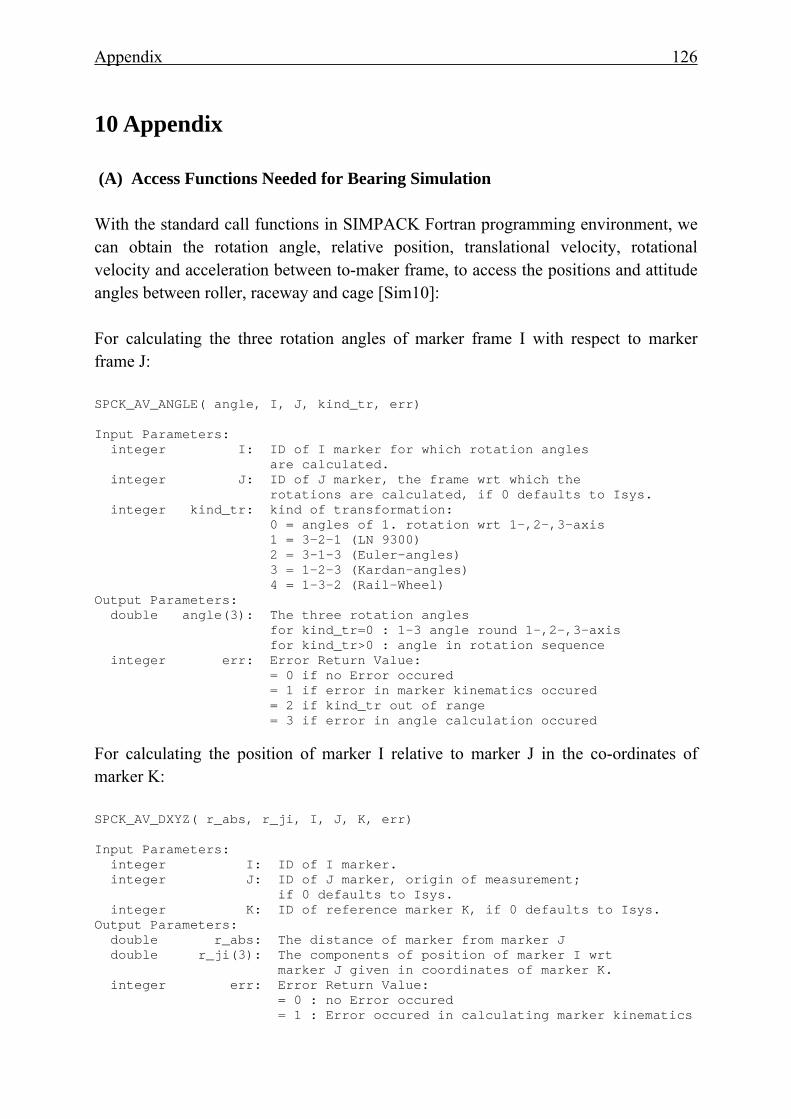
Appendix 126
10 Appendix (A) Access Functions Needed for Bearing Simulation With the standard call functions in SIMPACK Fortran programming environment, we can obtain the rotation angle, relative position, translational velocity, rotational velocity and acceleration between to-maker frame, to access the positions and attitude angles between roller, raceway and cage [Sim10]: For calculating the three rotation angles of marker frame I with respect to marker frame J: SPCK_AV_ANGLE( angle, I, J, kind_tr, err) Input Parameters: integer I: ID of I marker for which rotation angles are calculated. integer J: ID of J marker, the frame wrt which the rotations are calculated, if 0 defaults to Isys. integer kind_tr: kind of transformation: 0 = angles of 1. rotation wrt 1-,2-,3-axis 1 = 3-2-1 (LN 9300) 2 = 3-1-3 (Euler-angles) 3 = 1-2-3 (Kardan-angles) 4 = 1-3-2 (Rail-Wheel) Output Parameters: double angle(3): The three rotation angles for kind_tr=0 : 1-3 angle round 1-,2-,3-axis for kind_tr>0 : angle in rotation sequence integer err: Error Return Value: = 0 if no Error occured = 1 if error in marker kinematics occured = 2 if kind_tr out of range = 3 if error in angle calculation occured
For calculating the position of marker I relative to marker J in the co-ordinates of marker K: SPCK_AV_DXYZ( r_abs, r_ji, I, J, K, err) Input Parameters: integer I: ID of I marker. integer J: ID of J marker, origin of measurement; if 0 defaults to Isys. integer K: ID of reference marker K, if 0 defaults to Isys. Output Parameters: double r_abs: The distance of marker from marker J double r_ji(3): The components of position of marker I wrt marker J given in coordinates of marker K. integer err: Error Return Value: = 0 : no Error occured = 1 : Error occured in calculating marker kinematics
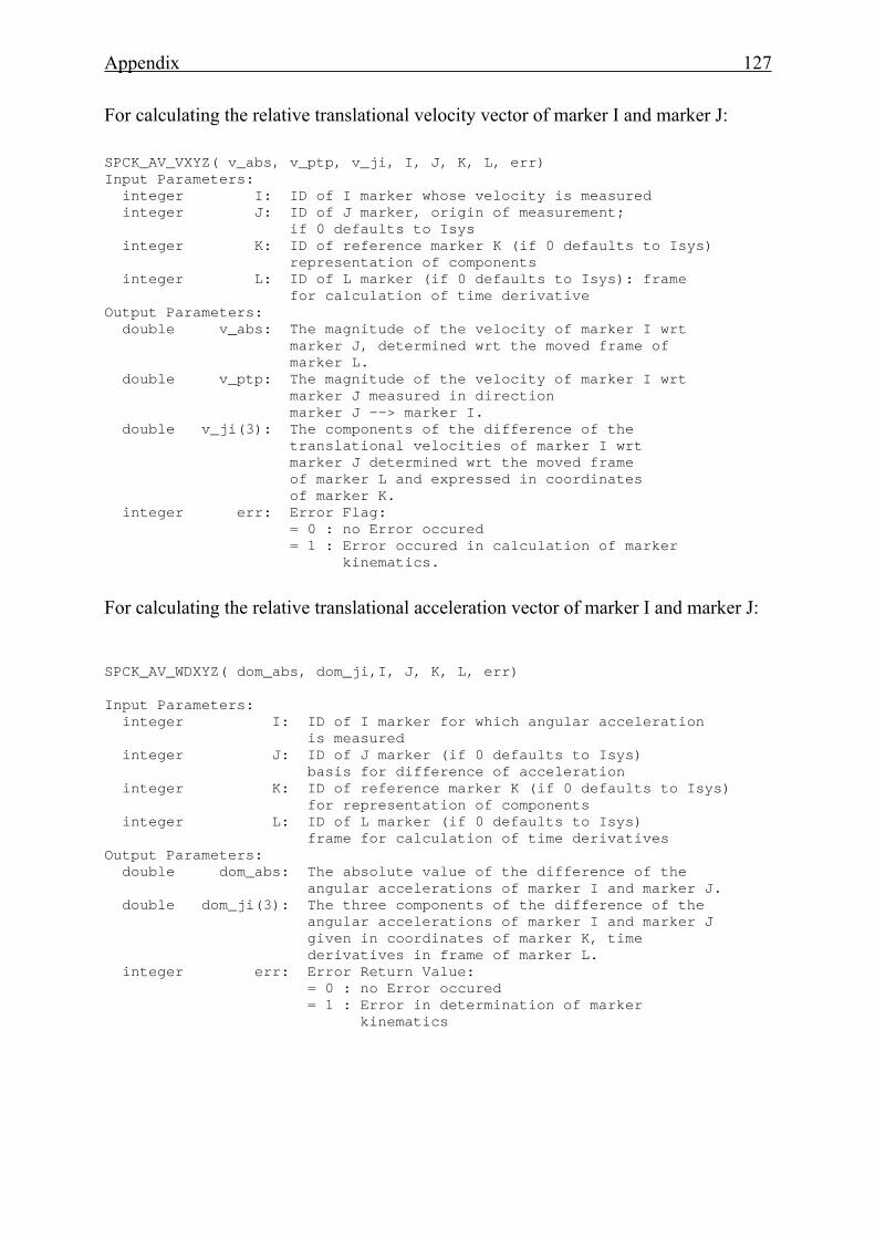
Appendix 127
For calculating the relative translational velocity vector of marker I and marker J: SPCK_AV_VXYZ( v_abs, v_ptp, v_ji, I, J, K, L, err) Input Parameters: integer I: ID of I marker whose velocity is measured integer J: ID of J marker, origin of measurement; if 0 defaults to Isys integer K: ID of reference marker K (if 0 defaults to Isys) representation of components integer L: ID of L marker (if 0 defaults to Isys): frame for calculation of time derivative Output Parameters: double v_abs: The magnitude of the velocity of marker I wrt marker J, determined wrt the moved frame of marker L. double v_ptp: The magnitude of the velocity of marker I wrt marker J measured in direction marker J --> marker I. double v_ji(3): The components of the difference of the translational velocities of marker I wrt marker J determined wrt the moved frame of marker L and expressed in coordinates of marker K. integer err: Error Flag: = 0 : no Error occured = 1 : Error occured in calculation of marker kinematics.
For calculating the relative translational acceleration vector of marker I and marker J: SPCK_AV_WDXYZ( dom_abs, dom_ji,I, J, K, L, err) Input Parameters: integer I: ID of I marker for which angular acceleration is measured integer J: ID of J marker (if 0 defaults to Isys) basis for difference of acceleration integer K: ID of reference marker K (if 0 defaults to Isys) for representation of components integer L: ID of L marker (if 0 defaults to Isys) frame for calculation of time derivatives Output Parameters: double dom_abs: The absolute value of the difference of the angular accelerations of marker I and marker J. double dom_ji(3): The three components of the difference of the angular accelerations of marker I and marker J given in coordinates of marker K, time derivatives in frame of marker L. integer err: Error Return Value: = 0 : no Error occured = 1 : Error in determination of marker kinematics
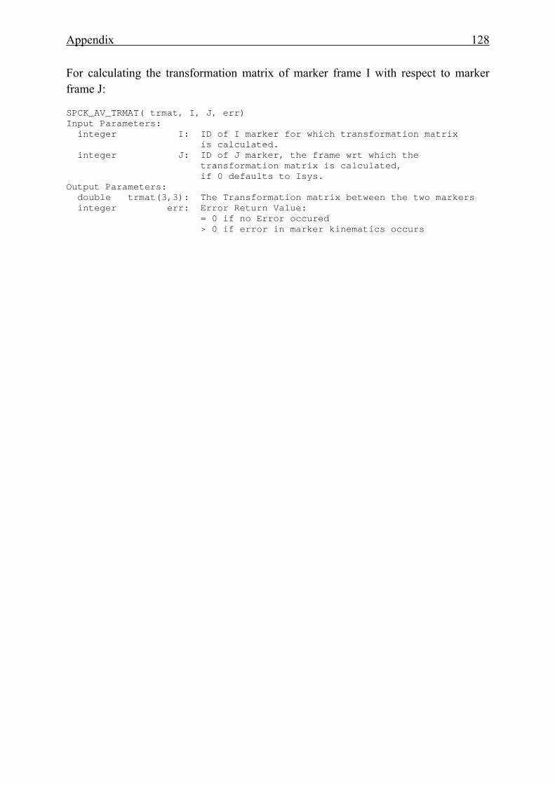
Appendix 128
For calculating the transformation matrix of marker frame I with respect to marker frame J: SPCK_AV_TRMAT( trmat, I, J, err) Input Parameters: integer I: ID of I marker for which transformation matrix is calculated. integer J: ID of J marker, the frame wrt which the transformation matrix is calculated, if 0 defaults to Isys. Output Parameters: double trmat(3,3): The Transformation matrix between the two markers integer err: Error Return Value: = 0 if no Error occured > 0 if error in marker kinematics occurs
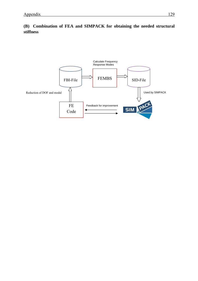
Appendix 129
(B) Combination of FEA and SIMPACK for obtaining the needed structural stiffness
FE Code
SID-File
FBI-File
FEMBS
Reduction of DOF and modal
Calculate Frequency Response Modes
Used by SIMPACK
Feedback for improvement
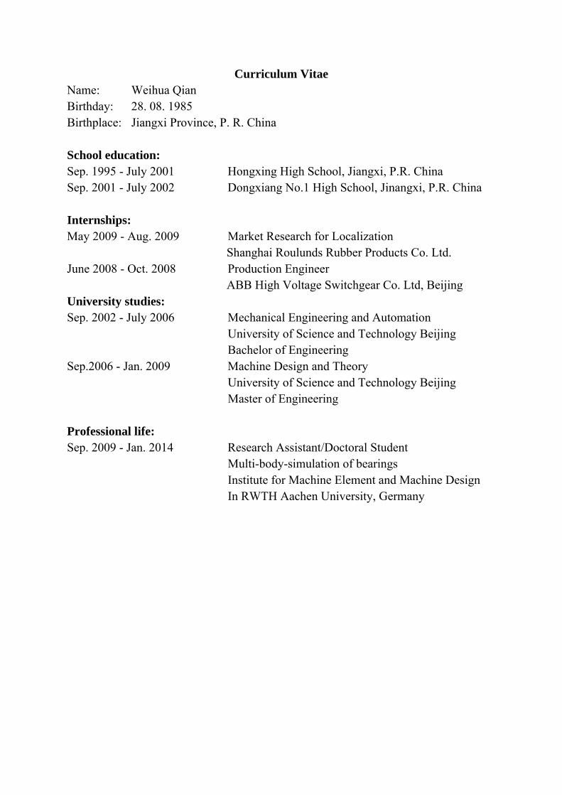
Curriculum Vitae Name: Weihua Qian Birthday: 28. 08. 1985 Birthplace: Jiangxi Province, P. R. China School education: Sep. 1995 - July 2001 Hongxing High School, Jiangxi, P.R. China Sep. 2001 - July 2002 Dongxiang No.1 High School, Jinangxi, P.R. China Internships: May 2009 - Aug. 2009 Market Research for Localization Shanghai Roulunds Rubber Products Co. Ltd. June 2008 - Oct. 2008 Production Engineer ABB High Voltage Switchgear Co. Ltd, Beijing University studies: Sep. 2002 - July 2006 Mechanical Engineering and Automation University of Science and Technology Beijing Bachelor of Engineering Sep.2006 - Jan. 2009 Machine Design and Theory University of Science and Technology Beijing Master of Engineering Professional life: Sep. 2009 - Jan. 2014 Research Assistant/Doctoral Student Multi-body-simulation of bearings Institute for Machine Element and Machine Design In RWTH Aachen University, Germany
Related Documents