3 rd IFToMM International Symposium on Robotics and Mechatronics 2 – 4 October 2013, Singapore DYNAMIC FRICTION MODEL FOR TENDON-SHEATH ACTUATED SURGICAL ROBOTS: MODELLING AND STABILITY ANALYSIS 1 T.N. DO, 1 T. TJAHJOWIDODO, 2 M.W.S. LAU, 1 S.J. PHEE 1 School of Mechanical and Aerospace Engineering, Nanyang Technological University, 50 Nanyang Avenue, Singapore 639798. [email protected], [email protected], [email protected] 2 School of Mechanical and Systems Engineering, Newcastle University International Singapore (NUIS), 180 Ang Mo Kio, Avenue 8, Block P, Room 220, Singapore 569830. [email protected] This paper presents a novel dynamic friction model for flexible tendon-sheath mechanism in surgical robots. It allows for accurate modelling of both sliding and presliding regimes. Unlike existing approaches in the literature, the novel model employs not only velocity information but also acceleration information and it is able to capture nonlinear hysteresis characteristics using a unique equation. In addition, transition between two regimes is guaranteed to be smooth without using any switching functions and it permits an arbitrary configuration of sheath, i.e. helical and spatial shape. The model incorporates a set of velocity and acceleration dependent equations with a differential function and it is independent configuration of the tendon-sheath mechanism. Moreover, characterization of different dynamic properties for the novel model has been shown in terms of existence and uniqueness for the solution, bounded input-bounded output (BIBO) stability, and dissipative property. The proposed model has been experimentally reported with arbitrary input signals. It assures an accurate prediction of nonlinear hysteresis behavior between the tendon and the sheath. It also represents a significant application in haptic feedback in surgical systems and higher fidelity for control purposes. INTRODUCTION Robotic assistance for minimally invasive surgery (MIS) has been given much attention in surgical communities during the past few years and has overcome many drawbacks in open surgical procedures. MIS has many benefits such as a reduction of trauma and healing time, reduction of lost blood, enhancement of better cosmetic and faster recovery for the patients. The size and dexterities of surgical tools have been improving, making them suitable for more complex tasks in surgical operations as in intracorporeal suturing. To actuate these systems, tendon-sheath mechanism is preferred. The tendon-sheath system can pass through a long narrow and tortuous path, meaning that it can operate in small working areas, and allows for a drastic reduction of system size. Moreover, it does not require high electrical power or actuator at distal end to operate the slave. The need of flexible actuation such as low bulkiness, high maneuverability and degrees of freedom, small in size, light weight, cheaper and simpler design, and safety on human body, have made the tendon-sheath a very suitable mode for transmission. However, the nonlinearities in the tendon-sheath cause major challenges not only in the modelling but also in enhancing system performances. To tackle these drawbacks, a few available tendon- sheath analyses have been proposed in the literature. Typical approaches for a discrete lumped mass model of a single tendon sheath under the assumptions of uniform distribution tendon curvature and tendon pretension along the sheath are proposed by Kaneko et al. [1-3], Palli and Melchiorri [4, 5]. However, these works are still limited by discontinuous problems when the system operates at areas near zero velocity. They lead to the degradation of system performance

Welcome message from author
This document is posted to help you gain knowledge. Please leave a comment to let me know what you think about it! Share it to your friends and learn new things together.
Transcript
3rd
IFToMM International Symposium on Robotics and Mechatronics 2 – 4 October 2013, Singapore
DYNAMIC FRICTION MODEL FOR TENDON-SHEATH ACTUATED SURGICAL ROBOTS: MODELLING AND STABILITY ANALYSIS
1T.N. DO,
1T. TJAHJOWIDODO,
2M.W.S. LAU,
1S.J. PHEE
1 School of Mechanical and Aerospace Engineering, Nanyang Technological University, 50
Nanyang Avenue, Singapore 639798. [email protected], [email protected], [email protected]
2 School of Mechanical and Systems Engineering, Newcastle University International Singapore
(NUIS), 180 Ang Mo Kio, Avenue 8, Block P, Room 220, Singapore 569830.
This paper presents a novel dynamic friction model for flexible tendon-sheath mechanism in
surgical robots. It allows for accurate modelling of both sliding and presliding regimes. Unlike
existing approaches in the literature, the novel model employs not only velocity information but
also acceleration information and it is able to capture nonlinear hysteresis characteristics using a
unique equation. In addition, transition between two regimes is guaranteed to be smooth without
using any switching functions and it permits an arbitrary configuration of sheath, i.e. helical and
spatial shape. The model incorporates a set of velocity and acceleration dependent equations with a
differential function and it is independent configuration of the tendon-sheath mechanism.
Moreover, characterization of different dynamic properties for the novel model has been shown in
terms of existence and uniqueness for the solution, bounded input-bounded output (BIBO)
stability, and dissipative property. The proposed model has been experimentally reported with
arbitrary input signals. It assures an accurate prediction of nonlinear hysteresis behavior between
the tendon and the sheath. It also represents a significant application in haptic feedback in surgical
systems and higher fidelity for control purposes.
INTRODUCTION
Robotic assistance for minimally invasive surgery (MIS) has been given much attention in surgical
communities during the past few years and has overcome many drawbacks in open surgical
procedures. MIS has many benefits such as a reduction of trauma and healing time,
reduction of lost blood, enhancement of better cosmetic and faster recovery for the patients.
The size and dexterities of surgical tools have been improving, making them suitable for more
complex tasks in surgical operations as in intracorporeal suturing. To actuate these systems,
tendon-sheath mechanism is preferred. The tendon-sheath system can pass through a long narrow
and tortuous path, meaning that it can operate in small working areas, and allows for a drastic
reduction of system size. Moreover, it does not require high electrical power or actuator at distal
end to operate the slave. The need of flexible actuation such as low bulkiness, high
maneuverability and degrees of freedom, small in size, light weight, cheaper and simpler design,
and safety on human body, have made the tendon-sheath a very suitable mode for transmission.
However, the nonlinearities in the tendon-sheath cause major challenges not only in the modelling
but also in enhancing system performances. To tackle these drawbacks, a few available tendon-
sheath analyses have been proposed in the literature. Typical approaches for a discrete lumped
mass model of a single tendon sheath under the assumptions of uniform distribution tendon
curvature and tendon pretension along the sheath are proposed by Kaneko et al. [1-3], Palli and
Melchiorri [4, 5]. However, these works are still limited by discontinuous problems when the
system operates at areas near zero velocity. They lead to the degradation of system performance
and pose challenges in the control of the device. For the same approach, Agrawal et al. [6, 7]
developed an elegant discretized model for a pair of tendon sheath using a set of partial differential
equations. Low et al. [8] and Phee et al. [9] modeled the tendon sheath with a series of segments.
However, the hysteresis problems in presliding regime have not been solved so far. In addition,
their model approach is dependent configuration and if the tendon-sheath is flexible, these works
are not able to capture nonlinear hysteresis phenomena between tendon and sheath. It is known
that the friction model have been extensively studied in many approaches. Typically, the friction
model is combined by the presliding regime and sliding regime. Canudas de Wit et al. [10]
designed a novel dynamic friction model to overcome discontinuous problem when system in
stationary states. Swevers et al. [11] introduced the Leuven friction model for both regimes and
relaxed the shortcomings of the LuGre by incorporating local memory in model structure. Al-
Bender et al. [12] developed a Generalized Maxwell Slip (GMS) friction model, which is able to
represent the hysteresis behavior of both regimes and overcomes the disadvantages in the LuGre
and the Leuven model. Unfortunately, these current models cannot capture the hysteresis
phenomena of friction in the tendon-sheath mechanism. To account for this, a new friction model
that is able to represent the hysteresis in both sliding and presliding regimes is necessary. In our
previous approach [13], to capture the nonlinear friction behaviors in the pre-sliding regime for
tendon sheath, we have developed a new dynamic friction model using a modified normalized
Bouc-Wen model of hysteresis and a set of advanced Stribeck curves. This model tracks quite well
the nonlinear hysteresis in both regimes using unique element and it is independent configuration
of the sheath. Although the model used velocity and acceleration information to yield a good
approximation for the hysteresis loops, there are still some drawbacks such as weakly dissipative
properties and a large number of model parameters. To deal with these problems, in this paper, we
integrated the model equations into a unique function. This model also allows for arbitrary input
signals and reduces the number of model parameters as long as the accumulated curve angles are
maintained. In addition, the mathematical properties of our proposed model will be presented in
terms of the basis of stability analyses. These analyses guarantee conditions of global stability for
the model approach, ensure a unique solution of model parameters, and help for future control
purposes. The novel structure of our proposed model promises an optimal solution for both
position control and haptic feedback problems in flexible endoscopic systems.
DYNAMIC PROPERTIES OF FRITION IN TENDON-SHEATH MECHANISM
The typical transmission characteristics of a tendon-sheath system were described in the
approaches of Phee et al. [9], Agrawal et al. [6], Palli et al. [14], Kaneko et al. [1], and Do et
al.[15]. In this paper, a new dynamic friction model that allow for utilizing a lower number of
model parameters is presented and explored. The model structure is type of independent
configuration of the sheath shape and it is able to adapt with any input excitations under the
assumption of accumulated curve angles of the sheath configuration are maintained. The detailed
relations for tendon sheath friction with respect to position, velocity information are shown in
Figure 1. When the tendon at the input side is pulled (phase 1), the tendon tension for the output
side will remain nearly constant before starting to increase with the input tendon. This phase is
normally considered as the presliding regime (small displacement). After an interval of time, the
tendon tension at both sides reaches an approximate linear relation when they enter phase 2 which
is the sliding regime. When the tension force is released at the input side, a similar behaviour will
occur in the opposite direction, as is shown in phase 3 and 4. The curves ABC, CDE, EGI, and
IHA correspond to the phase 1, 2, 3, and 4 respectively. From these analyses, it is believed that the
hysteresis properties of the friction force between the tendon and the sheath must employ not only
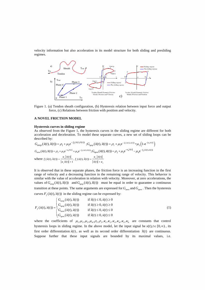
velocity information but also acceleration in its model structure for both sliding and presliding
regimes.
Phase 3Phase 4
Phase 1
Phase 2
0
Tin
Tout
Tendon
Sheatha)
b)
Tin
Tout
Figure 1. (a) Tendon sheath configuration, (b) Hysteresis relation between input force and output
force, (c) Relations between friction with position and velocity.
A NOVEL FRICTION MODEL
Hysteresis curves in sliding regime
As observed from the Figure 1, the hysteresis curves in the sliding regime are different for both
acceleration and deceleration. To model these separate curves, a new set of sliding loops can be
described by:
31( )( ( ), ( ))
1 1 21( ( ), ( ))
1 1( ( ), ( )) ; ( ( ), ( )) e + 1-ex tf x t x t
apvp
f x t x t
anvpG x t x t e G x t x t
4 2 4 2( ) ( ( ), ( ))
2 3 4
( ) ( ( ), ( ))
2 3 4( ( ), ( )) e e ; ( ( ), ( )) e e
x t f x t x tanvn
x t f x t x tapvnG x t x t G x t x t
where 51
1 2
2 6
( )( )( ( ), ( )) , ( ( ), ( ))
( ) 1 ( )
x tx tf x t x t f x t x t
x t x t
It is observed that in these separate phases, the friction force is an increasing function in the first
range of velocity and a decreasing function in the remaining range of velocity. This behavior is
similar with the value of acceleration in relation with velocity. Moreover, at zero accelerations, the
values of ( ( ), ( ))anvpG x t x t and ( ( ), ( ))apvpG x t x t must be equal in order to guarantee a continuous
transition at these points. The same arguments are expressed for anvnG and apvnG . Then the hysteresis
curves ( ( ), ( ))fF x t x t in the sliding regime can be expressed by:
( ( ), ( )) if ( ) 0, ( ) 0
( ( ), ( )) if ( ) 0, ( ) 0 ( ( ), ( ))
( ( ), ( )) if ( ) 0, ( ) 0
anvp
apvp
f
anvn
G x t x t x t x t
G x t x t x t x tF x t x t
G x t x t x t x t
( ( ), ( )) if ( ) 0, ( ) 0 apvnG x t x t x t x t
(1)
where the coefficients of 1 2 3 4 1 2 1 2 3 4 5 6, , , , , , , , , , ,
are constants that control
hysteresis loops in sliding regime. In the above model, let the input signal be ( ), [0, )x t t , its
first order differentiation ( )x t , as well as its second order differentiation ( )x t are continuous.
Suppose further that these input signals are bounded by its maximal values, i.e.
max max max( ) , ( ) , ( )x t x x t x x t x . On set max max max( ) | ( ) , ( ) , ( )B x t R x t x x t x x t x ,
equation ( ( ), ( ))fF x t x t is also bounded by max( ( ( ), ( ))) min( ( ( ), ( )))f fF x t x t and F x t x t .
A novel friction model for both regimes
Consider a physical phenomenon of the friction force that has hysteresis components and that can
be represented by a map ( ) ( )x t F t and is given by:
1( ) ( ) ( ) ( )
( ) ( ) 1 sgn sgn ( )( , ) ( , ) ( , ) ( , )
f f f f
n nt t t t
t x t x tF x x F x x F x x F x x
(2)
( ) ( )F t t (3)
The coefficients 0, 0, 1, 0n are dimensionless and they control the shape and size of the
hysteresis loops; ( ) :[0, )t R denotes the internal state parameter for the novel model and is
absolutely continuous. It is noted that the model given by Eq. (2) and Eq. (3) is a modification of
the Bouc-Wen model [16]. When 1fF , the Eq. (2) becomes the original Bouc-Wen model. The
signum function in Eq. (2) represents hysteresis phases of the model in each of four regions where
sgn( ( )) 0x t if ( ) 0x t , sgn( ( )) 1x t if ( ) 0x t , and sgn( ( )) 1x t if ( ) 0x t . Consider the four
regions of the model given by Eq. (2) and Eq. (3) with respect to the sign of velocity ( )x t and
internal state ( )t ; the following sets are defined by:
1 2( ) | ( ) 0, ( ) 0 , ( ) | ( ) 0, ( ) 0x t R x t t x t R x t t
3 4( ) | ( ) 0, ( ) 0 , ( ) | ( ) 0, ( ) 0x t R x t t x t R x t t
Inside these sets, Eq. (2) becomes:
; 2 1 1 2
( ) ( )( ) ( ) 1 ( ) ( ) 1
( , ) ( , ): :
f f
n nt t
t x t t x tF x x F x x
: ; : 2 1 3 4
( ) ( )( ) ( ) 1 ( ) ( ) 1
( , ) ( , )f f
n nt t
t x t t x tF x x F x x
(4)
In each set, Eq. (2) and (3) represent exactly the hysteresis loops as described in Figure 1. It is
noted that the proposed model at steady state, i.e. ( ) 0t , will become the hysteresis curves
( ( ), ( ))fF x t x t given by Eq. (5). Moreover, in each case for ( ) 0t and ( ) 0t , the hysteresis
curves are continuous with respect to ( )x t . This property will be used in the next section.
DYNAMIC PROPERTIES FOR THE NOVEL FRICTION MODEL
This section shows the mathematical properties of the novel friction model given by Eq. (2) and
Eq. (3) in terms of the existence and uniqueness of its solution, the Bounded Input Bounded
Output (BIBO) stability property, and dissipative property. The analyses are based on several
theorems and lemmas that are appropriate for stability properties of the novel model [17].
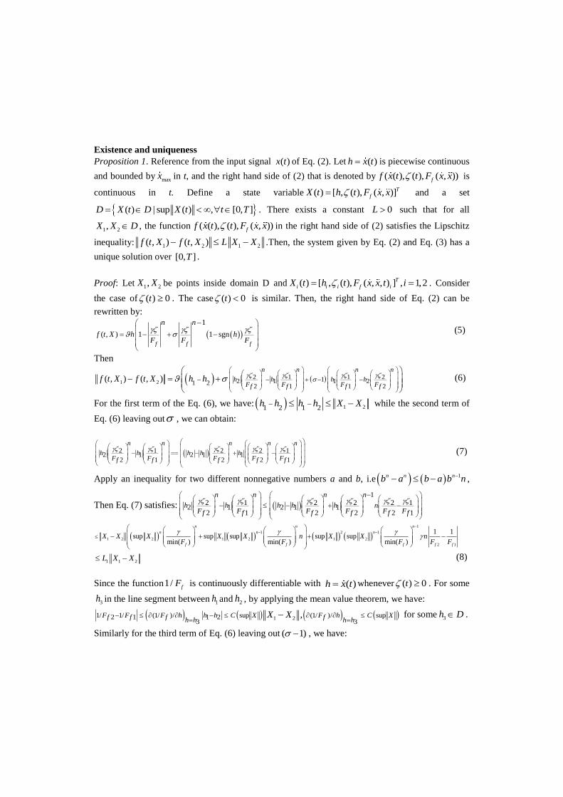
Existence and uniqueness
Proposition 1. Reference from the input signal ( )x t of Eq. (2). Let ( )h x t is piecewise continuous
and bounded by maxx in t, and the right hand side of (2) that is denoted by ( ( ), ( ), ( , ))ff x t t F x x is
continuous in t. Define a state variable ( ) [ , ( ), ( , )]T
fX t h t F x x and a set
( ) | sup ( ) , [0, ]D X t D X t t T . There exists a constant 0L such that for all
1 2,X X D , the function ( ( ), ( ), ( , ))ff x t t F x x in the right hand side of (2) satisfies the Lipschitz
inequality: 1 2 1 2( , ) ( , )f t X f t X L X X .Then, the system given by Eq. (2) and Eq. (3) has a
unique solution over [0, ]T .
Proof: Let 1 2,X X be points inside domain D and ( ) [ , ( ), ( , , ) ] , 1,2T
i i i f iX t h t F x x t i . Consider
the case of ( ) 0t . The case ( ) 0t is similar. Then, the right hand side of Eq. (2) can be
rewritten by:
1
( , ) 1 1 sgn
f f f
n n
f t X h hF F F
(5)
Then
1 2
2 1 1 21 2 1 1 21 22 1 1 2
( , ) ( , )n n n n
h h h hF F F Ff f f f
f t X f t X h h
(6)
For the first term of the Eq. (6), we have: 1 21 2 1 2h h h h X X while the second term of
Eq. (6) leaving out , we can obtain:
2 1 2 2 12 1 2 1 1
2 1 2 2 1
n n n n n
h h h h hF F F F Ff f f f f
(7)
Apply an inequality for two different nonnegative numbers a and b, i.e 1n n nb a b a b n ,
Then Eq. (7) satisfies: 1
2 1 2 2 2 12 1 2 1 1
2 1 2 2 2 1
n n n n
h h h h h nF F F F F Ff f f f f f
1
1 2 1
1 2 2 1 2 1 2
2 1
1 1sup sup sup sup sup
min( ) min( ) min( )
n n n
n n n
f f f f f
X X X X X n X X nF F F F F
1 1 2L X X (8)
Since the function1/ fF is continuously differentiable with ( )h x t whenever ( ) 0t . For some
3h in the line segment between 1h and 2h , by applying the mean value theorem, we have:
1 21/ 1/ (1/ )/ sup (1/ )/ sup2 1 1 23 3
,F F F h h h C X F h C Xf f f fh h h hX X
for some
3h D .
Similarly for the third term of Eq. (6) leaving out ( 1) , we have:
1 2 1 1 1 2 1 1 21 2 1 2 2 2 1 2 2
1 2 1 1 1 2 1 1 2
n n n n n n n n n
h h h h h h h h hF F F F F F F F Ff f f f f f f f f
2
11 1
sup sup sup sup sup (sup )1 2 1 2 1 2 1min( ) min( ) min( )
n n nn n n
X X X X X n X X n C XF F F
f f f
2 1 2L X X (9)
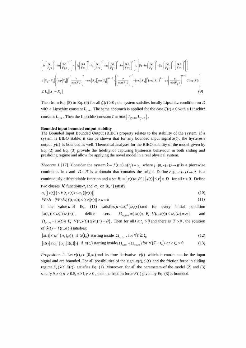
Then from Eq. (5) to Eq. (9) for all ( ) 0t , the system satisfies locally Lipschitz condition on D
with a Lipschitz constant 0L . The same approach is applied for the case ( ) 0t with a Lipschitz
constant 0L . Then the Lipschitz constant 0 0max ,L L L .
Bounded input bounded output stability
The Bounded Input Bounded Output (BIBO) property relates to the stability of the system. If a
system is BIBO stable, it can be shown that for any bounded input signal ( )x t , the hysteresis
output ( )y t is bounded as well. Theoretical analyses for the BIBO stability of the model given by
Eq. (2) and Eq. (3) provide the fidelity of capturing hysteresis behaviour in both sliding and
presliding regime and allow for applying the novel model in a real physical system.
Theorem 1 [17]. Consider the system0 0( , ), ( )x f t x x t x where :[0, ) nf D R is a piecewise
continuous in t and nD R is a domain that contains the origin. Define :[0, )V D R is a
continuously differentiable function and a set ( ) | ( )n
rB x t R x t r D for all 0r . Define
two classes functions 1 and 2 on [0, ]r satisfy:
1 2( ) ( , ( )) ( )x t V t x t x t (10)
/ ( / ) ( , ( )) 0, ( ) 0V t V x f t x t x t (11)
If the value of Eq. (11) satisfies 1
2 1( )r and for every initial condition
1
0 2 1( ) ( )x t r , define sets 2 ( ) 2( ) | ( , ( )) ( )rx t B V t x t and
1 ( ) 1( ) | ( , ( )) ( )r rx t B V t x t r . Then for all 0 0t t and there is 0T , the solution
of ( ) ( , ( ))x t f t x t satisfies:
1
1 2( ) ( )x t , if 0( )x t starting inside 2 ( ) , for 0t t (12)
1
1 2 0( ) ( ( ) )x t x t , if 0( )x t starting inside 1 2( ) ( )r for 0 0 0T t t t (13)
Proposition 2. Let ( ), [0, )x t t and its time derivative ( )x t which is continuous be the input
signal and are bounded. For all possibilities of the sign ( ), ( )x t t and the friction force in sliding
regime ( ( ), ( ))fF x t x t satisfies Eq. (1). Moreover, for all the parameters of the model (2) and (3)
satisfy 0, 0.5, 1, 0n , then the friction force ( )F t given by Eq. (3) is bounded.
Proof: It is easy to verify that the Proposition 2 is directly generated from Theorem 1 (see[17],
pages 172 and 675 for more details).
Passivity properties of the novel model
In this section, we provide a complete proposition for the condition of passivity properties of the
novel friction model given by Eq. (2) and Eq. (3).
Proposition 3. Consider the nonlinear dynamic system given by Eq. (2) and Eq. (3). For a mapping
( ) ( )x t F t , the system is dissipative with respect to the storage function2( ( )) ( ) / 2W t t ,
in the sense that all parameters and signals satisfied all aforementioned assumptions and the
following inequality holds:
( ) ( ) ( ( )) ( ) ( ) /x t F t W t t t (14)
Proof: It is obviously shown that the proposed model given by Eq. (2) and Eq. (3) always satisfies
the dissipative property of Eq. (14) that is ( ) ( ) ( ( )) ( ) ( ) /x t F t W t t t .
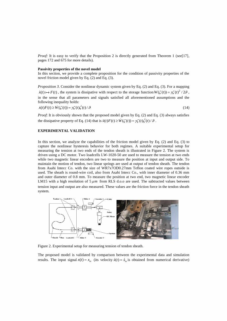
EXPERIMENTAL VALIDATION
In this section, we analyze the capabilities of the friction model given by Eq. (2) and Eq. (3) to
capture the nonlinear hysteresis behavior for both regimes. A suitable experimental setup for
measuring the tension at two ends of the tendon sheath is illustrated in Figure 2. The system is
driven using a DC motor. Two loadcells LW-1020-50 are used to measure the tension at two ends
while two magnetic linear encoders are two to measure the position at input and output side. To
maintain the motion of tendon, two linear springs are used at output of tendon sheath. The tendon
from Asahi Intecc Co. with the size of WR7x7OD0.27mm Teflon coated wire ropes outside is
used. The sheath is round-wire coil, also from Asahi Intecc Co., with inner diameter of 0.36 mm
and outer diameter of 0.8 mm. To measure the position at two end, two magnetic linear encoder
LM15 with a high resolution of 5 m from RLS d.o.o are used. The subtracted values between
tension input and output are also measured. These values are the friction force in the tendon sheath
system.
Figure 2. Experimental setup for measuring tension of tendon sheath.
The proposed model is validated by comparison between the experimental data and simulation
results. The input signal ( ) inx t x (its velocity ( ) inx t x is obtained from numerical derivative)
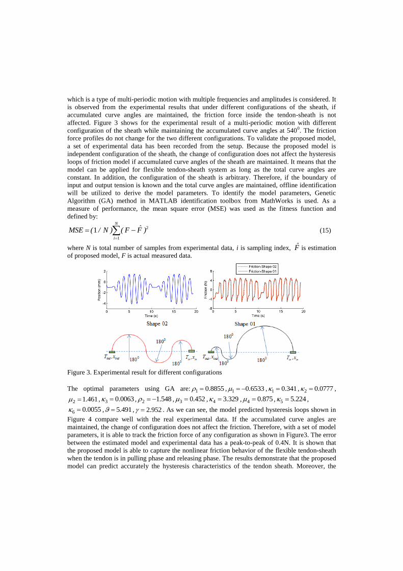
which is a type of multi-periodic motion with multiple frequencies and amplitudes is considered. It
is observed from the experimental results that under different configurations of the sheath, if
accumulated curve angles are maintained, the friction force inside the tendon-sheath is not
affected. Figure 3 shows for the experimental result of a multi-periodic motion with different
configuration of the sheath while maintaining the accumulated curve angles at 5400. The friction
force profiles do not change for the two different configurations. To validate the proposed model,
a set of experimental data has been recorded from the setup. Because the proposed model is
independent configuration of the sheath, the change of configuration does not affect the hysteresis
loops of friction model if accumulated curve angles of the sheath are maintained. It means that the
model can be applied for flexible tendon-sheath system as long as the total curve angles are
constant. In addition, the configuration of the sheath is arbitrary. Therefore, if the boundary of
input and output tension is known and the total curve angles are maintained, offline identification
will be utilized to derive the model parameters. To identify the model parameters, Genetic
Algorithm (GA) method in MATLAB identification toolbox from MathWorks is used. As a
measure of performance, the mean square error (MSE) was used as the fitness function and
defined by:
2
1
1N
i
ˆMSE ( / N ) ( F F )
(15)
where N is total number of samples from experimental data, i is sampling index, F̂ is estimation
of proposed model, F is actual measured data.
Figure 3. Experimental result for different configurations
The optimal parameters using GA are: 1 0.8855 , 1 0.6533 , 1 0.341 , 2 0.0777 ,
2 1.461 , 3 0.0063 , 2 1.548 , 3 0.452 , 4 3.329 , 4 0.875 , 5 5.224 ,
6 0.0055 , 5.491 , 2.952 . As we can see, the model predicted hysteresis loops shown in
Figure 4 compare well with the real experimental data. If the accumulated curve angles are
maintained, the change of configuration does not affect the friction. Therefore, with a set of model
parameters, it is able to track the friction force of any configuration as shown in Figure3. The error
between the estimated model and experimental data has a peak-to-peak of 0.4N. It is shown that
the proposed model is able to capture the nonlinear friction behavior of the flexible tendon-sheath
when the tendon is in pulling phase and releasing phase. The results demonstrate that the proposed
model can predict accurately the hysteresis characteristics of the tendon sheath. Moreover, the
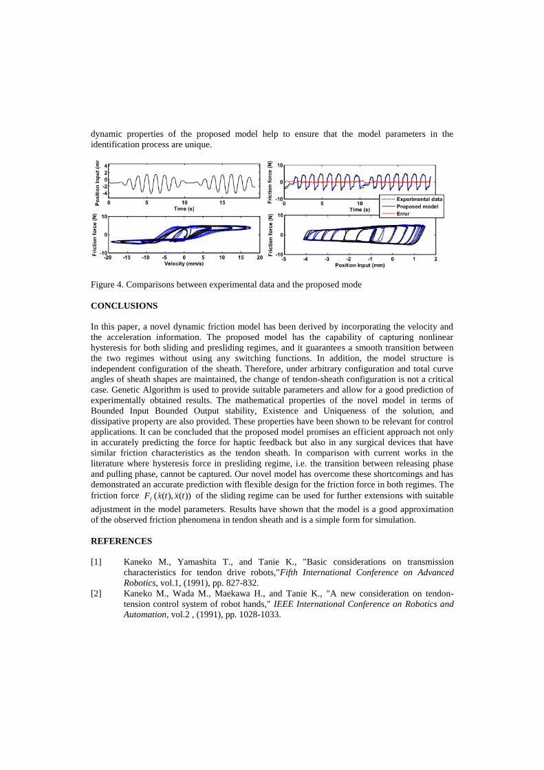
dynamic properties of the proposed model help to ensure that the model parameters in the
identification process are unique.
Figure 4. Comparisons between experimental data and the proposed mode
CONCLUSIONS
In this paper, a novel dynamic friction model has been derived by incorporating the velocity and
the acceleration information. The proposed model has the capability of capturing nonlinear
hysteresis for both sliding and presliding regimes, and it guarantees a smooth transition between
the two regimes without using any switching functions. In addition, the model structure is
independent configuration of the sheath. Therefore, under arbitrary configuration and total curve
angles of sheath shapes are maintained, the change of tendon-sheath configuration is not a critical
case. Genetic Algorithm is used to provide suitable parameters and allow for a good prediction of
experimentally obtained results. The mathematical properties of the novel model in terms of
Bounded Input Bounded Output stability, Existence and Uniqueness of the solution, and
dissipative property are also provided. These properties have been shown to be relevant for control
applications. It can be concluded that the proposed model promises an efficient approach not only
in accurately predicting the force for haptic feedback but also in any surgical devices that have
similar friction characteristics as the tendon sheath. In comparison with current works in the
literature where hysteresis force in presliding regime, i.e. the transition between releasing phase
and pulling phase, cannot be captured. Our novel model has overcome these shortcomings and has
demonstrated an accurate prediction with flexible design for the friction force in both regimes. The
friction force ( ( ), ( ))fF x t x t of the sliding regime can be used for further extensions with suitable
adjustment in the model parameters. Results have shown that the model is a good approximation
of the observed friction phenomena in tendon sheath and is a simple form for simulation.
REFERENCES
[1] Kaneko M., Yamashita T., and Tanie K., "Basic considerations on transmission
characteristics for tendon drive robots,"Fifth International Conference on Advanced
Robotics, vol.1, (1991), pp. 827-832.
[2] Kaneko M., Wada M., Maekawa H., and Tanie K., "A new consideration on tendon-
tension control system of robot hands," IEEE International Conference on Robotics and
Automation, vol.2 , (1991), pp. 1028-1033.
[3] Kaneko M., Paetsch W., and Tolle H., "Input-dependent stability of joint torque control
of tendon-driven robot hands," IEEE Transactions on Industrial Electronics, vol. 39,
(1992), pp. 96-104.
[4] Palli G. and Melchiorri C., "Model and control of tendon-sheath transmission systems,"
In Proceedings of IEEE International Conference on Robotics and Automation ICRA,
(2006), pp. 988-993.
[5] Palli G. and Melchiorri C., "Optimal control of tendon-sheath transmission systems," in
8th International IFAC Symposium on Robot Control, SYROCO, September 6, 2006 -
September 8, 2006, Bologna, Italy.
[6] Agrawal V., Peine W. J., and Yao B., "Modeling of Transmission Characteristics Across
a Cable-Conduit System," IEEE Transactions on Robotics, vol. 26, (2010), pp. 914-924.
[7] Agrawal V., Peine W. J., Yao B., and Choi S., "Control of cable actuated devices using
smooth backlash inverse," IEEE International Conference on Robotics and Automation
(ICRA), (2010), pp. 1074-1079.
[8] Low S. C., Phee S.J., Valdastri P., Menciassi A., and Dario P., "Tendon sheath analysis
for estimation of distal end force and elongation," IEEE/ASME International Conference
on Advanced Intelligent Mechatronics(AIM), (2009), pp. 332-337.
[9] Phee S. J., Low S. C., Dario P., and Menciassi A., "Tendon sheath analysis for estimation
of distal end force and elongation for sensorless distal end," Robotica, vol. 28, (2010), pp.
1073-1082.
[10] Canudas de Wit C., Olsson H., Astrom K. J., and Lischinsky P., "A new model for
control of systems with friction," IEEE Transactions on Automatic Control, vol. 40,
(1995), pp. 419-425.
[11] Swevers J., Al-Bender F., Ganseman C. G., and Projogo T., "An integrated friction model
structure with improved presliding behavior for accurate friction compensation," IEEE
Transactions on Automatic Control, vol. 45, (2000), pp. 675-686.
[12] Al-Bender F., Lampaert V., and Swevers J., "The generalized Maxwell-slip model: a
novel model for friction Simulation and compensation," IEEE Transactions on Automatic
Control, vol. 50, (2005),pp. 1883-1887.
[13] Do T. N., Tjahjowidodo T., Lau M. W. S., and Phee S. J., "An Investigation of Friction-
Based Tendon Sheath Model Appropriate for Control Purposes," Mechanical Systems and
Signal Processing, (2012).
[14] Palli G., Borghesan G., and Melchiorri C., "Modeling, Identification, and Control of
Tendon-Based Actuation Systems," IEEE Transactions on Robotics, vol. PP, (2011),pp.
1-14,.
[15] Do T. N., Tjahjowidodo T., Lau M. W. S., and Phee S. J.,"Nonlinear Modeling and
Parameter Identification of Dynamic Friction Model in Tendon Sheath for Flexible
Endoscopic Systems " ICINCO 2013 - Proceedings of the 10th International Conference
on Informatics in Control, Automation and Robotics, Iceland, (2013).
[16] Ismail M., Ikhouane F., and Rodellar J., "The Hysteresis Bouc-Wen Model, a Survey,"
Archives of Computational Methods in Engineering, vol. 16, (2009), pp. 161-188.
[17] Khalil H. K., “Nonlinear systems”, Upper Saddle River, N.J. : 3rd ed., Prentice Hall,
(c2002).
Related Documents


![Giant cell tumor of tendon sheath in the hand: analysis of risk ......and being giant cell tumor of the tendon sheath (GCTT S) the most common form [1–5]. The pathogenesis of GCTTS](https://static.cupdf.com/doc/110x72/60935d76623e6068eb220bb6/giant-cell-tumor-of-tendon-sheath-in-the-hand-analysis-of-risk-and-being.jpg)


