Reprinted from the IMAC-XVII Proceedings, 1999, with permission of the Society for Experimental Mechanics, Inc., 7 School Street, Bethel, CT 06801, 203-790-6373, Fax 203-790-4472, email [email protected], http://www.sem.org. 7 DYNAMIC FE MODELLING OF A MULTI-STOREY CAR PARK VERIFIED BY MODAL TESTING P. Reynolds, A. Pavic and P. Waldron University of Sheffield Centre for Cement and Concrete Sir Frederick Mappin Building Mappin Street, Sheffield, S1 3JD United Kingdom ABSTRACT. This paper describes the application of the FE modelling, modal testing and FE model correlation and updating techniques to a 1500-tonne car park floor structure. Firstly, a pre-test FE model, constructed according to common civil engineering practice, is presented. Next, the modal testing performed on the structure is described and the results from this testing are shown. Finally, the manual FE model updating procedure as applied to this structure is described and the correlation between the updated FE model and the test results is presented. By using this procedure, inadequacies in the pre-test FE model are highlighted and suggestions are made for better modelling practice for similar future structures. 1. INTRODUCTION Consideration of the vibration performance of civil engineering structures is becoming increasingly important with the current trend for more efficient and slender structural forms. In particular, long-span concrete floors, which traditionally have suffered few vibration problems, are becoming more lively due to improvements in their construction technology. A programme of research is currently underway at the University of Sheffield which is transferring advanced modal testing and analysis technologies from the mechanical and aeronautical disciplines to the civil engineering sector. The aim of this technology transfer is to provide more reliable analytical models suitable for checking the vibration serviceability of long-span and slender concrete floors. Obvious problems with civil engineering structures, such as their size and the fact that they must be tested in noisy open space environments, mean that this transfer of technology is by no means a simple process. This paper describes the application of the modal testing and analysis technologies to a full-scale reinforced concrete floor structure in a multi-storey car park. The pre-test analysis [1] comprising the construction of an FE model according to common civil engineering practice is presented, followed by a description of the modal testing and its results. Finally, limited manual FE model updating is performed to demonstrate the deficiencies in the initial modal, which are then used to suggested guidelines for the modelling of future similar structures. 2. THE TEST STRUCTURE The test structure was a single floor in a multi-storey car park. It weighed approximately 1500 tonnes and is illustrated in Figure 1. The floor was constructed from conventionally reinforced concrete and consisted of a number of precast concrete beams of a proprietary design connected together with cast in-situ reinforced concrete. This system formed a ribbed slab with a slab depth of 75 mm and an overall depth (including ribs) of 500 mm. The slab was supported by three rows of columns which were assumed to be rigidly connected

Welcome message from author
This document is posted to help you gain knowledge. Please leave a comment to let me know what you think about it! Share it to your friends and learn new things together.
Transcript

8/4/2019 Dynamic Fe Modelling of a Multi-storey Car Park
http://slidepdf.com/reader/full/dynamic-fe-modelling-of-a-multi-storey-car-park 1/7
Reprinted from the IMAC-XVII Proceedings, 1999, with permission of the Society for Experimental Mechanics, Inc., 7 School Street, Bethel,
CT 06801, 203-790-6373, Fax 203-790-4472, email [email protected], http://www.sem.org.
7
DYNAMIC FE MODELLING OF A MULTI-STOREY CAR PARK
VERIFIED BY MODAL TESTING
P. Reynolds, A. Pavic and P. Waldron
University of Sheffield
Centre for Cement and Concrete
Sir Frederick Mappin Building
Mappin Street, Sheffield, S1 3JD
United Kingdom
ABSTRACT. This paper describes the application of
the FE modelling, modal testing and FE model
correlation and updating techniques to a 1500-tonne
car park floor structure. Firstly, a pre-test FE model,
constructed according to common civil engineering
practice, is presented. Next, the modal testing
performed on the structure is described and the results
from this testing are shown. Finally, the manual FE
model updating procedure as applied to this structure
is described and the correlation between the updated
FE model and the test results is presented. By usingthis procedure, inadequacies in the pre-test FE model
are highlighted and suggestions are made for better
modelling practice for similar future structures.
1. INTRODUCTION
Consideration of the vibration performance of civil
engineering structures is becoming increasingly
important with the current trend for more efficient and
slender structural forms. In particular, long-span
concrete floors, which traditionally have suffered fewvibration problems, are becoming more lively due to
improvements in their construction technology.
A programme of research is currently underway at the
University of Sheffield which is transferring advanced
modal testing and analysis technologies from the
mechanical and aeronautical disciplines to the civil
engineering sector. The aim of this technology transfer
is to provide more reliable analytical models suitable
for checking the vibration serviceability of long-span
and slender concrete floors. Obvious problems with
civil engineering structures, such as their size and the
fact that they must be tested in noisy open space
environments, mean that this transfer of technology is
by no means a simple process.
This paper describes the application of the modal
testing and analysis technologies to a full-scale
reinforced concrete floor structure in a multi-storey
car park. The pre-test analysis [1] comprising theconstruction of an FE model according to common
civil engineering practice is presented, followed by a
description of the modal testing and its results.
Finally, limited manual FE model updating is
performed to demonstrate the deficiencies in the initial
modal, which are then used to suggested guidelines for
the modelling of future similar structures.
2. THE TEST STRUCTURE
The test structure was a single floor in a multi-storeycar park. It weighed approximately 1500 tonnes and is
illustrated in Figure 1. The floor was constructed from
conventionally reinforced concrete and consisted of a
number of precast concrete beams of a proprietary
design connected together with cast in-situ reinforced
concrete. This system formed a ribbed slab with a slab
depth of 75 mm and an overall depth (including ribs)
of 500 mm. The slab was supported by three rows of
columns which were assumed to be rigidly connected

8/4/2019 Dynamic Fe Modelling of a Multi-storey Car Park
http://slidepdf.com/reader/full/dynamic-fe-modelling-of-a-multi-storey-car-park 2/7
Reprinted from the IMAC-XVII Proceedings, 1999, with permission of the Society for Experimental Mechanics, Inc., 7 School Street, Bethel,
CT 06801, 203-790-6373, Fax 203-790-4472, email [email protected], http://www.sem.org.
8
to it, as well as a small number of shear walls. In-situ
cast edge beams were also present between the
peripheral columns. Finally, a system of four rampsconnected this slab to the adjacent car park levels.
Since the car park was constructed using a new system
of long-span concrete beams, the developers wanted to
check its vibration performance. It was recommended
that the combined FE analysis and modal testing
procedure would be the best method of accomplishing
this objective.
3. PRE-TEST FE MODELLING
A pre-test model was constructed according to
common civil engineering practice using the Ansys 5.2
FE code. The main floor area, being a ribbed slab, was
modelled using orthotropic shell elements (Shell63) in
which the stiffer direction represented the direction of
the ribs. The density of the concrete was adjusted to
take account of the fact that the slab was not of
uniform thickness. The edge beams were modelled
using beam elements having offset capability
(Beam44) and the columns and shear wall supports
were modelled using pins, which is a commonassumption in civil engineering dynamic modelling.
The ramps to the adjacent floors were assumed to be
horizontal for this model to simplify the geometry.
The dynamic modulus of elasticity for the concrete
was initially assumed to be 35 kN/mm2.
This configuration is illustrated in Figure 2 and the
first six natural frequencies and mode shapes
calculated from this model are presented in Table 1.
Figure 2: Configuration of Pre-Test FE Model
Figure 1: Layout of the Test Structure.

8/4/2019 Dynamic Fe Modelling of a Multi-storey Car Park
http://slidepdf.com/reader/full/dynamic-fe-modelling-of-a-multi-storey-car-park 3/7
Reprinted from the IMAC-XVII Proceedings, 1999, with permission of the Society for Experimental Mechanics, Inc., 7 School Street, Bethel,
CT 06801, 203-790-6373, Fax 203-790-4472, email [email protected], http://www.sem.org.
9
4. MODAL TESTING
4.1 Selection of Test Grid
From the pre-test modelling, it was clear that the
modal testing should performed on the whole floorarea, rather than on a small portion of the floor as
originally requested by the designers of the floor
structure. This is important to note since there are
many guidelines for the vibration serviceability
assessment of floors which consider only a beam-like
strip of the floor having a limited width. Such
simplified models cannot take account of the large
floor mass which is actually engaged in vibration and
hence they tend to be overconservative.
For the tests described in this paper, which were
performed during construction, there were severe time
constraints imposed. The entire modal testing had to
be completed on two consecutive overnight sessions.
For this reason, a very coarse test grid containing 48
test points was selected as indicated in Figure 1.
However, to check whether or not this test grid wassufficient to describe all modes of interest without the
occurrence of spatial aliasing, an auto-MAC analysis
was performed for the first 10 modes. The auto-MAC
matrix is shown in Figure 3, indicating that the
selected test grid was adequate.
4.2 Condition of the Structure
Since the car park was still under construction at the
time of the tests, the contractor was asked to remove
any large items of equipment or materials from the
floor being tested. However, whilst most items had
been removed, there were several small piles of
materials left on the floor in addition to a fork-lift
truck. These could not be moved by the test personnel
and had to be left in place for the duration of the
testing. These sorts of practical problems are very
common when testing civil engineering structures,especially during construction.
There were also two temporary supports (props) which
provided vertical restraint to a small portion of the
floor when tested. The location of these props is
indicated in Figure 1. Since the existence of the these
props was not included in the pre-test FE model of the
structure, it was expected that the modal test results
would not be consistent with it. The location of these
Figure 3: Auto-MAC Plot for the Selected Test Grid
Mode Nat. Freq.
(Hz)
Mode Shape
1 5.70
2 6.14
3 6.73
4 7.25
5 7.97
6 8.22
Table 1: Results from Pre-Test FE Analysis.

8/4/2019 Dynamic Fe Modelling of a Multi-storey Car Park
http://slidepdf.com/reader/full/dynamic-fe-modelling-of-a-multi-storey-car-park 4/7
Reprinted from the IMAC-XVII Proceedings, 1999, with permission of the Society for Experimental Mechanics, Inc., 7 School Street, Bethel,
CT 06801, 203-790-6373, Fax 203-790-4472, email [email protected], http://www.sem.org.
10
props was carefully measured for inclusion in the
updated FE models of the structure.
4.3 Modal Testing Procedures
Quality assurance procedures based on those
recommended by the UK Dynamic Testing Agency(DTA) [2,3] were followed throughout the test to
ensure that good quality data were obtained. These
procedures are described in detail by Pavic et al. [4]
and are not repeated in great detail here.
The structure was tested using excitation provided by
an APS Dynamics 113 electrodynamic shaker, capable
of applying a peak sinusoidal force of 130 N. It was
operated in 'free-armature mode', meaning that it was
placed onto the top surface of the floor and the force
was generated by accelerating reaction masses
attached to the shaker armature. The force was gauged
indirectly by measuring the acceleration of the moving
masses. The excitation signal utilised was 'triggered
random' as described by Taber et al. [5]. The response
of the structure was measured using low noise, high
sensitivity (1000 mV/g) Endevco 7754-1000
piezoelectric accelerometers. In these tests, the shaker
was used as a roving exciter and two fixed response
measurement locations were used as indicated in
Figure 1. The use of the roving shaker is unusual, but
is very practical when testing large-scale floors [4].
Both the excitation and response signals were digitallysampled on site using a Diagnostic Instruments DI-
2200 dual-channel portable spectrum analyser which
provided immediate calculation and storage of
frequency response functions (FRFs). In addition, the
excitation and response signals were recorded using a
Racal StorePlus VL analogue tape recorder for later
re-sampling, if required.
As a part of the QA system adopted, some limited
modal parameter estimation was performed on site,
using a portable notebook PC with the ICATS suite of software. This was done to ensure that the acquired
data were of reasonable quality. Any FRF
measurements which appeared to have been spoiled
were repeated.
4.4 Results from Modal Testing
The measured natural frequencies, modal damping
ratios and mode shapes corresponding to the first six
modes of vibration are presented in Table 2. They
have been expanded [6] to a more detailed finiteelement mesh for ease of visualisation.
It is clear from a visual comparison of the measured
and predicted modal properties (Tables 1 and 2) that
there are significant differences. In particular, the most
notable are:
• the natural frequencies predicted by the pre-test
FE model are lower than those measured in the
modal testing,
• the effect of the temporary props can be seen
clearly, and
• the visual comparison between the measured and
calculated pairs of the fourth and higher modes is
visibly worse than for the first three modes.
Obviously, the pre-test FE model was unsuitable for
accurate calculation of the modal properties of this
floor structure. Therefore, an improved model was
developed which is presented in Section 5.
Mode Nat. Freq.
(Hz)
?
(%)
Mode Shape
1 6.41 0.78
2 6.82 2.88
3 7.32 2.38
4 7.58 1.82
5 7.99 1.10
6 8.50 1.03
Table 2: Results from Modal Testing.
effect of
temporary supports
8/4/2019 Dynamic Fe Modelling of a Multi-storey Car Park
http://slidepdf.com/reader/full/dynamic-fe-modelling-of-a-multi-storey-car-park 5/7
Reprinted from the IMAC-XVII Proceedings, 1999, with permission of the Society for Experimental Mechanics, Inc., 7 School Street, Bethel,
CT 06801, 203-790-6373, Fax 203-790-4472, email [email protected], http://www.sem.org.
11
It also appeared, particularly for the first two modes,
that the magnitude of the mode shape ordinates was
lower than expected at points remote from the
response measurement location. It is possible that this
was an unfortunate effect of the very low signal-to-
noise ratio on the response channel caused by an
inability to excite this structure properly using theshaker. The authors believe, therefore, that for
structures significantly larger than this, a larger exciter
would be required.
5. FE MODEL CORRELATION AND MANUAL
UPDATING
Throughout the updating process, the degree of
correlation between the FE model and the test data
was determined primarily using the values of natural
frequencies and a visual inspection of the mode
shapes. However, for the more refined models which
had modal properties quite close to the test data, the
more formal correlation measures of Modal Assurance
Criterion (MAC) and Coordinate Modal Assurance
Criterion (COMAC) were used.
5.1 Manual Updating of the FE Model
The most significant improvements to the pre-test FE
model were achieved by:
• Explicit modelling of the columns. In civil
engineering practice, it has been common to
idealise column/slab connections as pin supports.
This inaccuracy in the boundary conditions has
been shown to reduce significantly the apparent
stiffness of the floor system [7]. For this reason,
the columns were included in the updated model.
They were assumed to be rigidly fixed at the
connection with the floors directly above and
below.
•
Explicit modelling of the temporary supports. Thetemporary supports which were encountered on
site were included in the updated FE model. Due
to their location, which, incidentally, was quite
close to an antinode of the first mode of vibration
corresponding to the unpropped structure, the
inclusion of these supports was found to be vital
to the accuracy of the updated model.
• Explicit modelling of the ribs. Rather than
approximating the ribbed slab structure as an
orthotropic slab, the relatively deep and narrow
ribs (Figure 1) were modelled explicitly using
offset beam elements (Beam44). However, this
greatly increased the complexity of the FE model
and produced only limited gains in accuracy. This
will be discussed further in Section 6.
• Modelling of the centre beam using shell elements.Since the centre beam was 1200 mm wide and
500 mm deep, the decision was taken to model it
using shell elements (Shell63). This enabled its
lateral stiffness to be reduced as described below.
• Other improvements. Other general improvements
and updates to the model included better
modelling of the structural geometry and
improvements in the idealisation of some of the
boundary conditions (such as at the ends of the
ramps which were modelled as fixed rather than
pinned).
In addition to these model refinements, material
properties which were deemed to be uncertain were
adjusted. The global dynamic modulus of elasticity
was varied since the inherent variability of concrete as
a material dictates that this parameter is always rather
uncertain. For this structure, the optimum value of
Young's modulus was determined to be 34 kN/mm2,
quite close to the originally assumed 35 kN/mm2.
There were also indications that there was some lack
of stiffness at the centre beam (indicated in Figure 1).
This was thought to be caused by a lack of continuityat this location due to the existence of the construction
joints between the precast concrete elements and the
in-situ cast concrete. To model this lack of continuity,
the dynamic modulus of the orthotropic shell
elements, representing the lateral stiffness of the
centre beam, was reduced to only 3.4 kN/mm2.
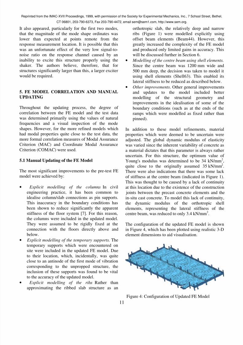
The configuration of the updated FE model is shown
in Figure 4, which has been plotted using realistic 3-D
element dimensions to aid visualisation.
Figure 4: Configuration of Updated FE Model

8/4/2019 Dynamic Fe Modelling of a Multi-storey Car Park
http://slidepdf.com/reader/full/dynamic-fe-modelling-of-a-multi-storey-car-park 6/7
Reprinted from the IMAC-XVII Proceedings, 1999, with permission of the Society for Experimental Mechanics, Inc., 7 School Street, Bethel,
CT 06801, 203-790-6373, Fax 203-790-4472, email [email protected], http://www.sem.org.
12
5.2 Results from Updated FE Model
The results calculated from the updated FE model are
presented in Table 3. It can be seen that the modal
properties predicted by the updated FE model are
significantly closer to those measured from testing
than the pre-test model (Table 1 and Figure 5). The
MAC plot presented in Figure 5 indicates a reasonable
correlation between the first four modes. However, the
COMAC plot indicates portions of the structure for
which the correlation is low, even for these first four
modes. These locations were identified as those which
were far from the accelerometer reference position forwhich it was thought that there was a poor signal to
noise ratio which reduced the quality of the measured
modal data.
Nevertheless, this updated FE model was considered
to be sufficiently accurate for further studies of floor
vibration serviceability under low-level dynamic
loading.
6. CONCLUSIONS
It has been demonstrated that an FE model constructed
according to common civil engineering modelling
practice was unable to predict accurately the modal
properties of a structure at the design stage. However,
it is not economically viable to model such structures
in intricate detail in the normal civil engineering
design office. For this reason, some suggestions are
made here so that a better prediction of dynamic
behaviour may be made using a reasonably economic
FE model.
Firstly, the presence of columns should be included
explicitly in an FE model of a reinforced concrete
floor structure, rather than simple pin supports. This
tends to produce results which correlate more closely
with measured data. More importantly, this
assumption has the overall effect of increasing the
stiffness and natural frequencies of the floor system.
This is, in general, more beneficial as to the floor
vibration serviceability.
Mode Nat. Freq.
(Hz)
Mode Shape
1 6.39
2 6.63
3 7.40
4 7.87
5 8.23
6 8.45
Table 3: Results from Updated FE Analysis.
Figure 5: Correlation between the Updated FE Model
and the Modal Test Data.
8/4/2019 Dynamic Fe Modelling of a Multi-storey Car Park
http://slidepdf.com/reader/full/dynamic-fe-modelling-of-a-multi-storey-car-park 7/7
Reprinted from the IMAC-XVII Proceedings, 1999, with permission of the Society for Experimental Mechanics, Inc., 7 School Street, Bethel,
CT 06801, 203-790-6373, Fax 203-790-4472, email [email protected], http://www.sem.org.
13
Due to the 'global' nature of the lowest modes of
vibration in floors, which are normally the most
important for vibration serviceability analysis, a
'smeared' distribution of mass and stiffness only is
required. Specifically, experience in modelling this
particular structure showed that the explicit modelling
of the ribs in this ribbed slab structure greatlyincreased the development and processing time for the
model. However, it only produced limited gains in
accuracy, as indicated by the results in Table 4 which
compares explicit versus smeared modelling of the
ribs with all other modelling details kept equal. The
authors suggest that such structures may be modelled
reasonably accurately in a design environment using
orthotropic shell elements, provided that the element
thickness and material properties are carefully
considered.
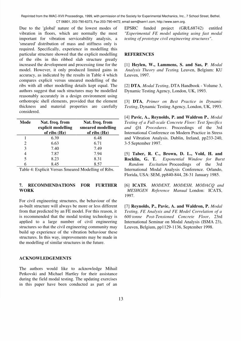
Mode Nat. freq. from
explicit modelling
of ribs (Hz)
Nat. freq. from
smeared modelling
of ribs (Hz)
1 6.39 6.48
2 6.63 6.71
3 7.40 7.49
4 7.87 7.94
5 8.23 8.31
6 8.45 8.57
Table 4: Explicit Versus Smeared Modelling of Ribs.
7. RECOMMENDATIONS FOR FURTHER
WORK
For civil engineering structures, the behaviour of the
as-built structure will always be more or less different
from that predicted by an FE model. For this reason, it
is recommended that the modal testing technology is
applied to a large number of civil engineering
structures so that the civil engineering community may
build up experience of the vibration behaviour these
structures. In this way, improvements may be made inthe modelling of similar structures in the future.
ACKNOWLEDGEMENTS
The authors would like to acknowledge Mihail
Petkovski and Michael Hartley for their assistance
during the field modal testing. The updating exercises
in this paper have been conducted as part of an
EPSRC funded project (GR/L68742) entitled
"Experimental FE model updating using fast modal
testing of prototype civil engineering structures".
REFERENCES
[1] Heylen, W., Lammens, S. and Sas, P. Modal
Analysis Theory and Testing. Leuven, Belgium: KU
Leuven, 1997.
[2] DTA, Modal Testing, DTA Handbook - Volume 3,
Dynamic Testing Agency, London, UK, 1993.
[3] DTA, Primer on Best Practice in Dynamic
Testing, Dynamic Testing Agency, London, UK, 1993.
[4] Pavic, A., Reynolds, P. and Waldron P., Modal
Testing of a Full-scale Concrete Floor: Test Specifics
and QA Procedures. Proceedings of the 3rd
International Conference on Modern Practice in Stress
and Vibration Analysis. Dublin, Ireland, pp233-240,
3-5 September 1997.
[5] Taber, R. C., Brown, D. L., Vold, H. and
Rocklin, G. T. Exponential Window for Burst
Random Excitation. Proceedings of the 3rd
International Modal Analysis Conference. Orlando,
Florida, USA: SEM, pp840-844, 28-31 January 1985.
[6] ICATS. MODENT, MODESH, MODACQ and
MESHGEN Reference Manual. London: ICATS,
1997.
[7] Reynolds, P., Pavic, A. and Waldron, P. Modal
Testing, FE Analysis and FE Model Correlation of a
600 tonne Post-Tensioned Concrete Floor , 23rd
International Seminar on Modal Analysis (ISMA 23),
Leuven, Belgium, pp1129-1136, September 1998.
Related Documents