2C .7.15 C' 2C: - ? zw x 33CCO (C3T~di o~ NRL Memorandum Report 54154 Dynamic Design Analysis of a Foundation Undergoing Unequal Support- Shock Motion GEORGE J. OWHARA AND PATRICK F. CUNNIFF Spuctural Integrity Branch Mfarine Technology Division September 22, 1983 Ar SEP 2 9 IMS j NAVAL R~ESE~ARCH LABORATORY -- Washigton, DX. kpproved for public telease, distrbutio-n unlimited. ~o c

Welcome message from author
This document is posted to help you gain knowledge. Please leave a comment to let me know what you think about it! Share it to your friends and learn new things together.
Transcript
2C .7.15 C' 2C: - ? zw x 33CCO (C3T~di o~
NRL Memorandum Report 54154
Dynamic Design Analysisof a Foundation Undergoing Unequal
Support- Shock Motion
GEORGE J. OWHARA AND PATRICK F. CUNNIFF
Spuctural Integrity BranchMfarine Technology Division
September 22, 1983
Ar
SEP 2 9 IMS
j NAVAL R~ESE~ARCH LABORATORY
-- Washigton, DX.
kpproved for public telease, distrbutio-n unlimited.
~o c

SECURITY CLASSIFICATION Of T I PAGE ("o~n Date E..,...dJ
READ INSTRUCTIONSREPORT DOCMENTATION PAGE BEFORE COMPLETING FORmI -REPO:RT NUMBER 2. GOVT ACCESSION NO. 3. REC;PIENY*S CATALOG N4UM81ER
4. TTLIEandw~liio)S. TYPE OF REPORT & PERIOD COVERED
Interim report on a continuingDYNAMIC DESIGN ANALYSIS OF A FOUNDATION ~ rbeUNDERGOING UNEQUAL SUPPORT SHOCK MOTION G. PERFORMING ORG. REPORT NumIeRl
7. AUTHN(ej a. CONTRACT OR GRMANT NUMSER(a)
George J. O'Hara and Patrick F. Cunniff
S. PERFOAMING ORGANIZATION NAME AND ADDRESS 10. PROGRAM ELEMENT. PROJECT. TASKAREA A WORK UNIT HUM8ERS
Naval Research LaboratorySF44000Washington, DC 20375 DTNSRDC 23102 58-1345-00 '
11. CONTROLLING OFFICE NAME AND ADDRESS 12. REPORT DATE
September 22, 198313. NumSeR OF PAGES
3014. MONITORING AGENCY NAME II AODRESS'it diflefl tom Controing Office) 15. SIECURITY CLASS. (of this report)
UnclassifiedISa. DECLASSIFiCATION/DOW1NGRAOING
SCHEDULE
16. DISTRIUUTION STATEMENT (I this Report)
Approved for public release; distribution unlimited.
17. DISTRIOUTION STATEMENT (af the abstract @nested In 8lock 20.,I tliffierent fresh Report)
IS. SUPPLEMENTARY NOTES
It. KEY WORDS (Continue an reverse aids, It necessary and Identify by block number)
Foundation designShipboard shockDynamic design
20. A09TRACT (Conin" an revere. side It necoossiy and Identify by block aner
- A design analysis method developed earlier for small Shipboard foundations is extended tothose cases where the foundation supports experience unequal levels of shock excitation. Themethod utilizes an energy criterion such that the foundation may remain elastic or mayexperience elastic-plastic behavior in such a way as to insure against large deflections orunwanted collapse. Predicted load carrying capacity levels are developed for a sample foundationundergoing unequal support motion. In addition, results are compared with these obtained
(Continued)
DD I, AN 13 1473 COITION OF I NOV G5 IS OUSOLIETE
VN 010-014-601SECURITY CLASSIFICATION OF THIS PAGE (When Des Deeweod)

SECURITYV CLASSIFICATION Of YWIS PAGE (rIsI Do#* 1.-0d)
* 20. TRtACT (Caoitinuod)
oo er for equal levels of shock excitation of the foundation supports. The results are worked upSin detail, both theoretically and by numerical examples to show the ease of application andefficiency of the method.
SECURITY CLASSIFICATION OF THI9S PAGEt'1P&.. D4ta 80nteleE)
4 2i
1.
CONTENTS
INTROD UCTIO N ...............................................................................................................................
BACKGROUND..........................................................
A. Equipm ent Foundation System ........................................................................................ 1B. M ethod of Analysis .......................................................................................................... 2C. Equal Support M otion Results ......................................................................................... 2
SHOCK EXCITATIO N M O D EL ........................................................................................................ 2
ELASTIC AN ALYSIS ........................................................................................................................ 3
A. Elastic Failure Criteria ...................................................................................................... 3B. Equivalent Static Acceleration Design M ethod ............................................................... 4C. Energy Design M ethod ..................................................................................................... 4
ELASTIC-PLASTIC AN A LYSIS ........................................................................................................ 5
A . Lim it Analysis .................................................................................................................. 5B. Equivalent Static Acceleration Design M ethod ............................................................... 6C. Energy Design M ethod ..................................................................................................... 6
EQ UAL VERSUS UN EQ U AL SHOCK EXCITATION ..................................................................... 6
RESU LTS ........................................................................................................................................... 7
SUM M A RY ........................................................................................................................................ 8
REFERENCES .................................................................................................................................... 8
APPEN D IX A - Effects of Shear on Energy Calculations .................................................................. 9
APPEN D IX B- Sam ple Com putations ............................................................................................... 11
A PPEN D IX C - Three Hinged Propped Beam .................................................................................. 14
Accesston For
NTIS C A AT
DYIC A
-, Juz't if i '
ABy ...
Dist r*
iii 4
.--. _o. . . .

.,. ,.,. .,, ° ., . , . . -. ° .- -' o_ .-. . -' -' , ' - - ' -"-. '. - ." " " ) '- ".''" " - "
DYNAMIC DESIGN ANALYSIS OF A FOUNDATION UNDERGOINGUNEQUAL SUPPORT SHOCK MOTION
INTRODUCTION
A design procedure for small shipboard foundations undergoing mechanical shock excitation hasbeen the subject of earlier reports [1,21. The design method is applicable to equipment- foundationcombinations that may be modeled as single-degree-of-freedom (SDOF) systems. Since the static anddynamic stress and deflection patterns are the same for such systems. the actual energy stored in thefoundation as the system undergoes shock excitation may be compared with the total energy storagecapacity of the foundation. This approach provides the basis of an efficient design method of SDOFsystems that allows the foundation material either to remain elastic throughout the shock excitation orto experience some degree of plastic action.
The purpose of this report is to extend the application of the energy design method to those caseswhere the foundation supports experience unequal levels of shock excitation and to compare the resultswith those obtained earlier for equal levels of shock excitation of the foundation supports. A review ofboth the elastic and elastic-plastic design methods are also included for completeness of this report.
BACKGROUND
A. Equipment Foundation System
Consider the SDOF system attached to a moveable base as shown in Fig. 1. Let P be the weightof the equipment and an assigned portion of the foundation weight. The equipment foundation systemis designed to withstand the lesser of a 250-g equivalent static acceleration or a design shock spectrumvelocity level, Vd, equal to 8 ft/sec. Note that Vd - 2r/X, where f - natural frequency of the systemand X - relative displacement between the mass and the base.
For the spectrum velocity shock input let U, be the maximum kinetic energy of the SDOF systemthat the foundation must absorb, while Uf is the energy storage capacity of the system. The survivalcriteria for the equipment foundation combination is
U, < U1.(1That is, the maximum energy stored in the foundation must be less than or equal to the energy storagecapacity of the foundation in order for the structure to survive the shock excitation. Note that it isassumed that no energy is stored in the equipment.
Now consider the two propped cantilever beams shown in Fig. 2 that form the foundation for arigidly attached equipment. Each beam is a 10 WF 25 structural member and it is assumed that theyshare equally the load in vertical shock. The material is steel with a tensile and compressive yield pointof 50 ksi and a shear yield of 25 ksi. Young's modulus E - 30 x 106 psi and the shear modulusG - 12 x 106 psi. Figure 3 shows the critical dimensions of the cross-section of one of the beams.
Manuscript approved May 19. 1983

B. Method of Analysis
Figure 4 is a model of one of the propped beams in which loads w are placed at the points ofattachment of the equipment (whose total weight equals 4 w) to the beam. Note that in this report theSDOF system contains two discrete masses. Replace each equipment load w by a force of magnitude Pas shown in Fig. 5. Let P be the maximum allowable force that the beam can withstand for either elas-tic response or elastic-plastic response to occur under shock excitation.
The energy storage capacity of the beam consists of the bending energy Ub and the shear energyU,, which are defined as follows:
"-" f L I&2. . f E ( 2 )
u, - (3)
where M - bending moment, S - shear, I - moment of inertia, A cross-sectional area, a - ratio ofA to the web area, and L-length of the beam. Note that a is arbitrarily set equal to unity in theelastic-plastic design method in order to provide a conservative design. It is also noted that the earlierresults [1, 21 used beam reactions that were based on bending effects only. This assumption is nowsubstantiated by the results of Appendix A which examines the energy calculations when the sheareffects are included along with bending effects for determining the beam reactions and deflections.
C. Equal Support Motion Results
A summary of previous results [1, 2J for equal support shock excitation levels is shown in TableI. The data list the allowable weights that each propped beam may carry for the elastic failure criteriaand for the elastic-plastic analysis using the combined stress resultant failure criteria that is described inRef. 2. The design loads of 242.0 lb for the elastic design and 828.8 lb for the elastic-plastic design willbe used as the basis of comparison between equal and unequal foundation shock excitation.
Table I - Summaryof Allowable Weights (lb)
Carried by One Beam
Failure Criteria Design Approach250-g Energy
Absolute Elastic 157.4 242.0Elastic-Plastic 376.4 828.8
SHOCK EXCITATION MODEL
Suppose one of the foundation supports of the propped beam undergoes a shock excitation levelthat is different from that experienced by the other foundation support. It is assumed that the inertialforces and spectral velocities are distributed linearly along the length of the two-mass model of thebeam as shown in Fig. 6, where Fig. 6(a) is the case for maximum motion occurring at the pinned end,while Fig. 6(b) is for the maximum motion occurring at the clamped end. Note that is a propor-tionality factor such that
0.5 4 < 1. (4)When /3 - 0.5, one end of the beam remains stationary. Of course, the case of equal support motionoccurs when I - which was treated earlier [1, 21.
2
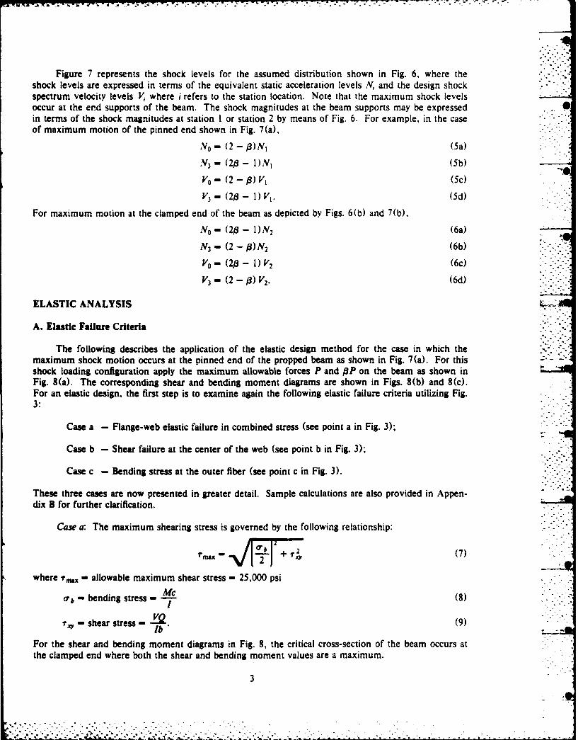
Figure 7 represents the shock levels for the assumed distribution shown in Fig. 6, where theshock levels are expressed in terms of the equivalent static acceleration levels N, and the design shockspectrum velocity levels V, where i refers to the station location. Note that the maximum shock levelsoccur at the end supports of the beam. The shock magnitudes at the beam supports may be expressed 0in terms of the shock magnitudes at station I or station 2 by means of Fig. 6. For example, in the caseof maximum motion of the pinned end shown in Fig. 7(a),
N0 - (2- f)N (5a)
N3 - (20 - l)N, (5b)Vo - Q2 - 0) V, (5c)
V3 - (2w- 1)V1 . (5d)
For maximum motion at the clamped end of the beam as depicted by Figs. 6(b) and 7(b),
N0 - (2e - 1)N2 (6a)
N3 - (2 -,8)N 2 (6b)
V0 - (2¢ - 1) V2 (6c)
ELASTIC ANALYSIS
A. Elastic Failure Criteria
The following describes the application of the elastic design method for the case in which themaximum shock motion occurs at the pinned end of the propped beam as shown in Fig. 7(a). For thisshock loading configuration apply the maximum allowable forces P and O9P on the beam as shown inFig. 8(a). The corresponding shear and bending moment diagrams are shown in Figs. 8(b) and 8(c).For an elastic design, the first step is to examine again the following elastic failure criteria utilizing Fig.3:
Case a - Flange-web elastic failure in combined stress (see point a in Fig. 3);
Case b - Shear failure at the center of the web (see point b in Fig. 3);
Case c - Bending stress at the outer fiber (see point c in Fig. 3).
These three cases are now presented in greater detail. Sample calculations are also provided in Appen-dix B for further clarification.
Case a: The maximum shearing stress is governed by the following relationship:
where ?'.x" allowable maximum shear stress - 25,000 psi
Mc- bending stress - - (8)
- shear stress - -O (9)lb
For the shear and bending moment diagrams in Fig. 8, the critical cross-section of the beam occurs atthe clamped end where both the shear and bending moment values are a maximum.
3
-- .: :;: .: .:-.: . : : : . :.: . : - . : .- : : -:. . . .- -.

Case b: The maximum shear occurs at the clamped end. Here, V - (13 + 23 1). Substitut-27
ing the maximum shear stress value of 25,000 psi into Eq. (9) along with the beam properties Q, I, andb, the magnitude of P is calculated for a given value of 13. I
Case c:. Again, the critical beam cross-section occurs at the clamped end whereM - 3 (4 + 5 S). Setting the maximum allowable bending stress equal to 50,000 psi into Eq. (8),3the allowable load P is calculated for any given value of 1.
It is interesting to note that for 1 - 1, P - 35, 310 lb which agrees with earlier results [1]. Formaximum motion of the pinned end and for 13 - 0.5, P - 50, 215 lb which represents the upper limitof P for all values of 3 given by Eq. (4).
B. Equivalent Static Acceleration Design Method
Having established the allowable value of P for a given 1, the load carrying capacity of thepropped beam is found for the equivalent static accelertion design criteria as follows:
P+O3P- PN (10)where i - total weight of the SDOF model for one beam
-2w + 2wf (refer to Fig. 4) (01)
wf- portion of the beam weight assumed at each point mass - 62.5 lbDue to the uneven distribution of the shock excitation as shown in Fig. 7(a) for maximum motion ofthe pinned end, rewrite Eq. (10) as follows:
P( + ) - N, + N2 (12)
where N2 -13 N, as shown in Fig. 6(a). Now
P" N (13)
or the load carrying capacity of one beam equals the following:
2w - 2wf. (14)N,
This equation may be expressed in terms of the maximum shock level occurring at the pinned end bymeans of Eq. (5a), i.e.,
2w- (2-)(2P) - 2 wf. (15)No
For example, if No - 250 g's and 1 - 0.5, the load carrying capacity of the beam equals
2w- (2 - 0.5) (2) (50,215) _ 125 - 477.6 lb.250
C. Energy Design Method
In order to analyze the beam foundation for the design shock spectrum velocity levels shown inFig. 7(a), the energy storage capacity of the beam is calculated using Eqs. (2) and (3), or directly fromthe shear and moment diagrams, i.e., by taking the moment of the shear and moment diagrams, prop-erly scaled, about their respective base lines. Details of the latter proceedure are given in Appendix B.
4a
,,,. , .' .. - ..- . - • " .- -.. . -. • " ' " "-. , ' -> _ --. . - " " '- " , " - -' " "

For example, using the data in Fig. 8 and #3 - 0.5 and P - 50,215 Ib, the total energy storage capacityU, - 5423 lb-in. The actual stored energy is obtained from the maximum kinetic energy of the SDOFsystem, i.e.,
U -;;IV2 j ~i 21V2J V (16)
2, 2 l 7 g
where V2 - 3 V1 for maximum motion of the pinned end of the beam. For the survival criteria, letU, - U,. Substituting these relationships along with Eq. (11) into Eq. (16) and rearranging terms, thefollowing expression results:
2w- 4g U, 125. (17)(I + p2) V2
Substituting Eq. (5c) into Eq. (17) for the case of maximum motion of the pinned end leads to the fol-lowing expression for the load carrying capacity of the beam:
4g(2 -,S)2 UT
2w- 4 125. (18)(1 +p 2) V02
Ifp -0.5, Ut - 5,423 lb-in., and if V0 - 96 in./sec, the load carrying capacity equals 1,512 lb.
Note that the foregoing results are applicable to the case in which maximum motion occurred atthe pinned end of the beam. Similar results could also be obtained for maximum motion of theclamped end so that the maximum force P would now be acting at station I and the force AP would be
acting at station 2.
ELASTIC-PLASTIC ANALYSIS
A. Limit Analysis
The first step in the elastic-plastic energy design method is to locate the plastic hinges for thestructure using limit analysis. Figure 9 shows the location of the hinges for maximim shock motion ofthe pinned end, while Fig. 10 provides the shear and bending moment diagrams for the case wherep - 0.5. Next, consider the interaction relationship between the shear force S and bending M asreported in Ref. 2:
-1- (19)
where M - limiting value of the bending moment in the absence of shear forcesSP - limiting value of the shear force in the absence of bending moments.
This relationship must be satisfied at each of the plastic hinge locations which has the effect of adjustingthe final shear and moment values throughout the beam. By examining the free-body diagram of thebeam to the left of the hinge at station 1 in Fig. 11, S - RL and M - 30 RL. Substituting into Eq.(19) along with S. - 184,000 lb and M. - 1,483,000 in.-lb for the given beam properties, the follow-ing maximum reaction at the pinned end is found:
RL [ MES - 47,740 lb.[900 S2 +M
At the clamped end of the beam the moment M - MR - (30 OP + 60 P - 90 RL) and the shearS - (P + pP - RL). Substituting into Eq. (19) yields P - 75, 750 lb. This is the magnitude of theforce P applied to the beam in Fig. 9 such that Eq. (19) is satisfied at stations I and 3 simultaneously.
5

-7 - ._7:
It should be noted that the location of the plastic hinges may change from that predicted by sim-pie limit analysis because of the interaction effects. This is so since limit analysis utilizes bendingeffects only while the interaction equation includes both bending and shearing effects. For example, forthe maximum shock motion occurring at the clamped end of the beam, the plastic hinges are located atstations I and 3 for ,A greater than 0.5 and less than or equal to unity by limit analysis. Upon furtherinvestigation, however, the interection effects of shear and bending as expressed by Eq. (19) locate thehinges at stations 2 and 3 for p < 0.6265. For / > 0.6265, the hinge at station 2 shifts to station Iwhile the hinge at station 3 remains fixed for all values of/3. The details for the special situation when
-0.6265 in which there are three hinges present simultaneously are found in Appendix C.
B. Equivalent Static Acceleration Design Method
Equation (15) is also applicable for obtaining the load carrying capacity of the beam by theelastic-plastic design method for maximum motion occurring at the pinned end of the beam. Forexample, in the above case of / - 0.5, substituting P - 75, 750 lb and N o - 250 g's into Eq. (15)yields a value 2w - 783.8 lb.
C. Energy Design Method
The procedure for calculating the load carrying capacity of the beam for the elastic-plastic energydesign approach is similar to that used for the elastic energy design method. For example, consider Fig.10 which shows the shear and bending moment diagrams for/3 - 0.5. Note that P - 75,750 lb asexplained earlier. The total energy storage capacity for this loading equals 9,644 lb-in. Using Eq. (18)for maximum motion of the pinned end of the beam, the load carrying capacity equals 2,786 lb.Details for applying the elastic-plastic method for the case where maximum motion occurs at theclamped end of the beam are found in Appendix B.
EQUAL VERSUS UNEQUAL SHOCK EXCITATION
It is interesting to examine an equipment foundation system that has already been designed forequal shock excitation, that is, a system capable of withstanding the lesser of a 250-g equivalent staticacceleration or a design shock spectrum velocity level of 8 ft/sec. The results of this analysis havealready been summarized in Table I. For example, according to the elastic failure criteria one of thepropped beams can carry a load of 242.0 lb based on the energy design method. Suppose this sameequipment foundation system is now subjected to unequal shock excitation at the foundation supports.The following question arises: what are the maximum shock levels at the foundation support pointsthat this system can withstand for a given /3?
Consider the case in which the maximum excitation occurs at the pinned end of the beam. Themaximum allowable equivalent static acceleration level No is obtained by rearranging Eq. (13) so that
2PN,
or by introducing Eq. (5a),
N o (2-)S) (2 P) (20)
The static acceleration level at the clamped end of the beam is found by using Eq. (5b), i.e.,
N3 - (2,8- 1) (2P) (21)
For the beam carrying 242.0 Ib,
- 242.0 + 125.0 - 367.0 lb.
6

For the case where 1-0.5, P- 50,215 lb as mentioned earlier. Therefore, N0 - 410.5 g's and
N 3 - 0 by means of Eqs. (20) and (21), respectively. That is, the equipment foundation system that
was originally designed for equal shock levels at each foundation support may withstand up to 410.5 g'sat the pinned end of the beam while the clamped end experiences a zero g-levei.
.. The maximum shock levels in terms of the design shock spectrum velocity may be obtained in asimilar fashion by rearranging Eq. (17) as follows:
" v' V1 1)
Substituting Eqs. (5c) and (5d) into this equation, the spectrum velocity levels at the end supports are
found as follows:
V-- (2 - 6) (22)
V3 - (2# - 1) 1 4g7U, (23).-. (I + p2);";-
Once again, consider the case where ; - 367.0 lb, 13 - 0.5, and U, - 5,423 lb-in for elastic behavior ofthe beam. Equations (22) and (23) yield V0 - 16.90 ft/sec and V3 - 0, respectively. Thus, a founda-tion system designed to withstand a design shock spectrum level of 8 ft/sec at each support can with-stand a level of 16.9 ft/sec at the pinned end of the beam when the clamped end remains stationary.
RESULTS
The results for the load carrying capacity of one of the beams that form the foundation are shownin Fig. 12. The abscissa is divided into two regions identified as the clamped/pinned ratio which equals(203 - 1)/(2 - 13) from Fig. 6(a), while the pinned/clamped ratio has,. similar relationship as seen inFig. 6(b). The results in Fig. 12 are for maximum end support shock levels of 250 g's and 8 ft/sec.Both elastic and elastic-plastic design results are included in the figure. In all cases it is seen that theload carrying capacity increases significantly as P approaches 0.5, that is, as the clamped/pinned ratioand the pinned/clamped ratio each approach zero. For example, when both foundations move alike,the load carrying capacity based upon the elastic energy design is 242.0 lb. This energy design levelincreases to 1,512 lb for the case when 03 - 0.5 for the pinned end undergoing shock excitation whilethe other end of the beam remains fixed. From the shape of these curves in Fig. 12, it is clear that themost severe design criteria occur when both supports move an equal amount, i.e., 1. - 1.
The elastic energy design curve for predicting the load carrying capacity and the correspondingelastic-plastic equivalent static acceleration design curve cross each other at two locations as shown inFig. 12. For example, in the clamped/pinned region, the crossover occurs at )9 equal to approximately
:'* 0.85. For 13 < 0.85, higher allowable loads are predicted by the elastic energy design method over the" elastic-plastic equivalent static acceleration design method. Similar results hold true for the
*.. pinned/clamped region for P3 < 0.6, although the effect is much less pronounced.
Another interesting observation of the curves in Fig. 12 occurs in the reversal of the load carryingcapacity levels. The larger elastic capacity levels occur for maximum motion at the pinned end of thebeam, while the larger elastic-plastic capacity levels occur for maximum motion at the clamped end ofthe beam. These phenomena are due primarily to the shape of the bending moment diagrams as shownin Fig. 13. These curves, drawn for 13 - 0.5, are used with Eq. (2) to obtain the bending energystorage capacity. It is noted that the Ub obtained from Fig. 13(a) is larger for the pinned end motion ofthe beam. Hence, a larger carrying capacity is obtained for the elastic design approach. Just the oppo-site occurs when Ut b is calculated by means of Fig. 13(b), so that a larger carrying capacity is obtainedfor the clamped end motion in the case of the elastic-plastic design method.
7Q..............°

Figure 14 is a summary of the results for the case where a beam, designed for equal supportmotion, is examined for the maximum allowable shock levels when this beam undergoes unequal foun-dation motion. Both elastic and elastic-plastic design level results are included in Fig. 14. Note that theg-levels in the left portion of the figure correspond to the equivalent static acceleration levels at thepinned end, namely N0 , while those levels in the right portion of the figure correspond to the clampedend levels N 3. Likewise, Fig. 15 shows the results for the same beam examined in terms of the designshock spectrum velocity limits.
Similar results are shown in Figs. 16 and 17 for the case of the beam designed for equal founda-tion motion by the elastic-plastic energy method. The load carrying capacity of the beam for this caseequals 828.8 lb as shown in Table 1.
SUMMARY
The extension of the elastic and elastic-plastic design methods developed earlier to those caseswhere unequal shock levels occur at the support points provide some interesting results. While theassumption is made that the unequal shock level inputs in terms of the inertial forces and spectral velo-cities are distributed linearly between the support points of the propped beams has not been validated,the results do provide an indication of the change in strength of the foundation beams. Thus, for
- 0.5 for all cases studied, the load carrying capacity increases significantly when compared with equalshock level inputs for 8 - 1. Likewise, the analysis showed that foundations already designed for equalshock loading at the support points can withstand correspondingly larger shock level inputs at the sup-port point undergoing maximum motion.
REFERENCES
1. O'Hara, G.J. and Cunniff, P.F., "Efficient Elastic Design of Small Foundations," NRL Memoran-dum Report 4886, September 1982.
2. O'Hara, G.J. and Cunniff, P.F., "Efficient Elastic-Plastic Design of Small Foundations," NRLMemorandum Report 4918 September 1982.
3. Blake, R.E. and Swick, E.S., "Dynamics of Linear Elastic Structures," NRL Report 4420, October1954.
4. Timoshenko, S. and MacCullough, G.H., "Elements of Strength of Materials," D. Van NostrandCo., 3rd Edition, 1949, p. 195.
8
S ... . ...
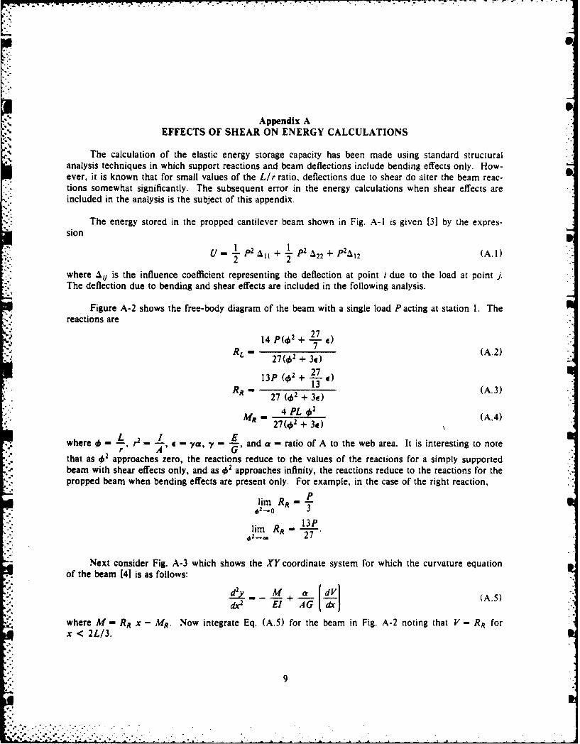
Appendix AEFFECTS OF SHEAR ON ENERGY CALCULATIONS
The calculation of the elastic energy storage capacity has been made using standard structuralanalysis techniques in which support reactions and beam deflections include bending effects only. How-ever, it is known that for small values of the Lir ratio, deflections due to shear do alter the beam reac-tions somewhat significantly. The subsequent error in the energy calculations when shear effects areincluded in the analysis is the subject of this appendix.
The energy stored in the propped cantilever beam shown in Fig. A-I is given [3] by the expres-sion
U p2 al+ 1 p2 p4U " T, A IP24A 22
+P2 1 2 (A.1)22where 1y is the influence coefficient representing the deflection at point i due to the load at point j.The deflection due to bending and shear effects are included in the following analysis.
Figure A-2 shows the free-body diagram of the beam with a single load P acting at station 1. Thereactions are
14 p(4 2 + L E)7RL - 2(2+E)(A.2)
13P (q)2 + L7 e)
RR 1 (A.3)27 (,02 + 3E)
4 PL 402MR - 4 + 32 (A.4)
27(102 + 3e)
where -' r2 C - - "ya, y - - and a - ratio of A to the web area. It is interesting to noter A G'that as 02 approaches zero, the reactions reduce to the values of the reactions for a simply supportedbeam with shear effects only, and as approaches infinity, the reactions reduce to the reactions for thepropped beam when bending effects are present only. For example, in the case of the right reaction,
lim RR --3
13Plim RR -
Next consider Fig. A-3 which shows the XY coordinate system for which the curvature equationof the beam [41 is as follows:
-- (A. 5)
where M - RR x - MR. Now integrate Eq. (A.5) for the beam in Fig. A-2 noting that V - RR forx < 2L/3.
9
.

. .w. . .
-R 'X + M R - + RR+ +2 +l~ C.(A.6)dy 2 EI El AG
The constant of integration C, is obtained using the boundary condition that at x 0. RRd-c AGThus, C,- 0. Integrating Eq. (A.6) and noting that at x -0, y -0, leads to the following forx- 2L/3:
4ML 3 [ 9 MefR 2 7 a ElI (A.7)
81 El 2L RR 2 AGL 2 "
Substituting Eqs. (A.3) and (A.4) into Eq. (A.7) and letting P - 1 yields the influence coefficient
2 L3 (10 4 + 297 e 2 + 729 e 2)
2187 El 4'2 (412 + 3e)
Note that2a L
liraA -- AAl G" - shear deflection of a simply supported'62-0 9A
beam subjected to a unit load at station 1. Also,20 L 3
lim A11 - 20 V - bending deflection of the proppedi _.. 2187 El
beam subjected to a unit load at station I.
Similar results may be obtained for the remaining influence coefficients that are summarized asfollows:
V3 (23 04 +675e 4,1+ 14 58 C2) --A21 - A2 - ( (A.9)
4374 E1 02(.02 + 3a)
L3(224 + 1188 e 02 + 2916 e2)4374 / 462 (02 + 3) --
These value-: for the influence coefficients are now substituted into Eq. (A. 1) to give the following:
P2 L3 (664 + 207 e#2 + 486 e2)486 E1 .02(462 + 3#)
Using the properties of the 10 WF 25 beam shown in Fig. 3 yields 40 - 21.14 and e - 7.92. For thesevalues
U 2 (A.13)285, 690'
This energy level compares with U - P2/(284,900) as reported in Ref. [11 when the contribution ofshear to the beam reactions and beam deflections were omitted. Figure A-4 summarizes the percenterror between the two methods for calculating U as a function of 4'. The error is less than two percentfor Lir ratios greater than 10. Consequently, this error is insignificant for most beams used in practice.Note that 4 - 21.14 for the propped beam examined in this report, so that the error is less than 0.5%for the energy calculations made herein and in earlier reports [1,21.
10
- . - - i .- ...- ... :.'- .. . .. . .... .. . .

Appendix BSAMPLE COMPUTATIONS
A. Elastic Failure Criteria
As an example of the elastic failure criteria consider the propped beam in Fig. 8 where/3 - 0.5.The maximum shear and bending moment occur at the fixed end where
PV- - (13 + 23p) - 0.907407 P
27M - lopP (12 + I5P) - 21.667 P.
9
Case a
- Mc (21.667 P) (4.603)oQs ... 0.748748 P133.2
r ±2 - (0.907407 P) (12.14) 0328183 P.lb (133.2) (0.252)
Substitute into Eq. (7).
(25,000)2 -0.74848 P + (0.328183 P) 2
P 50,215 lb.
Case b
For the shear failure at the center of the beam,
- (0.907407 P) (14.81)(133.2) (0.252)
P - 62,444 lb
Case c
For bending failure,
0000- (21.667 P) (5.04)133.2
P 60,988 lb.
Case a provides the smallest value so that P - 50, 215 lb is the design load.
Figure B-i shows the shear and moment diagrams for / - 0.5 when the maximum motion occursat the pinned end. The energy due to shear is calculated directly from the shear diagram as follows:U, 2 + 0 LO0 (0970 1)
', (0.592593)2 + (0.407407 p)2 + 0
21

-.. . . . . .. . . . . . . . . . . . . . . . . . . .-
"o4
AG .. _(20.108)P 2 16 (20.108) (50,215)2Ao [,4.j12 x 106 x 2.32
- 1821.2 lb-in.
For the bending energy,
Ub ' 0 (17.778 p)2 + 1 (17.778 - 5.556) P(30) 5.556 P + 12.222 PIE1121IT 2 1 3
D) 2 1 1 6. 1 2 2 1 23 .17 8 1+ 30 (5.556 p) + 1 (5.556 P)2 + 2.7 (21.667 P)21
5708.5 P2 5708.5 (50, 215)2El 30 X 106 x 133.2
U, - U, + U - 5423.4 lb-in.
B. Elastic-Plastic Analysis
The sample computations for the elastic-plastic design method are for the case where maximummotion occurs at the clamped end of the beam and - 0.5. Figure B-2(a) shows the free bodydiagram of the beam. Surprisingly, the theory of limit analysis predicts plastic hinges occurring simul-taneously at stations 1, 2, and 3. However, the interaction equation for bending and shear should besatisfied. In order to locate these positions, consider Fig. B-2(b) that shows the free body diagram ofthe beam to the right of station 2. Now
M 2 - 30 RR - MR. (B. 1)
Assuming there are hinges at stations 2 and 3, M 2 - MR so that
MR - 15 RR. (B.2)
From Fig. B-2(a),
90 RR- MR + 30 (0.5 P) + 60 P. (B.3)
Substituting for RR from Eq. (B.2), Eq. (B.3) reduces to M - 15 Pand therefore, R" P.
Apply Eq. (19) at either station 2 or station 3 as follows:
M + -
so that
where M.l - 1,483,000 in-lb and S. - 184,000 lb. This leads to P - 87,090.8 lb. Figure B.3 showsthe loading diagram and the corresponding shear and moment diagrams for the beam. Note that ahinge has not appeared at station 1. The following values are calculated as described earlier in thisappendix with the exception that a is set equal to unity for conservative results: U, - 1612.1 lb-in,Ub- 10,676.8 lb-in, and U, - 12,288.9 lb-in. The load carrying capacity is now calculated using Eq.(18).
4g(2 -,8)'U,_2w- -125
(1 + 02) Vo
". 12
-4(386.4) (1.5)2 (12. 288.9) -125
1.25 (96)'
3584.7 lb.
* 13

Appendix CTHREE HINGED PROPPED BEAM
The presence of three plastic hinges occurring simultaneously in the propped beam is now exam-
ined. Consider the case for maximum motion occurring at the clamped end of the propped cantilever
beam. The maximum loads acting on the beam are shown in Fig. C-1. Limit analysis indicates that for
, > 0.5 there are plastic hinges at stations 1 and 3. However, since the interaction equation must be
satisfied at the final location of the hinges, it can be shown that for
0.5 < (3 < 0.6265 (C.1)
hinges occur at stations 2 and 3, while for
0.6265 < 3 <1 (C.2)
hinges occur at stations I and 3. When 0 - 0.6265 three hinges exist simultaneously at stations 1,2,
and 3. This special case is now examined.
Assume that these three hinges exist simultaneously for the free body diagram of the beam in
Fig. C-1. Consider the section of the beam just to the left of station I as shown in Fig. C-2 and the
section of the beam just to the right of station 2 as shown in Fig. C-3. From Fig. C-2, M - 30 RL and
S - RL. Substituting into Eq. (19) gives RL - 47, 740 lb as reported earlier.
For the hinges at stations 2 and 3 consider Fig. C-3 where RR - S and M - MR since Eq. (19) is
satisfied simultaneously at these stations. Thus, 30 RR - 2 MR or MR - 15 Rt. Now
R 11 RA[L 2+ "12
so that RR - 87,091 lb and M - 1,306,361 in.-lb. Applying these reactions to Fig. C-I, the allowable
loads are found such that /3- 0.6265 and P -82,896 lb.
14
-. ... ..
It
Fig. I -Single degree of freedom system
EQUIPMENTASSUMED
RIGID
10 WF 25
1 3 30 -301"
SIDE VIEW
-~1 -T - -III
r --- T--
TOP VIEWFig. 2 - Equipment-roundlation combination
15
.~ .. .

0.437"
0 AREA = 7. 35 In 2
4.603" WEB AREA = 2.32 In 2
____ FLANGE AREA = 2.52 In 2
10.08" xx: 133.2 In4
0.252"
Fig. 3 - 10 WF 25 beam properties
10 WF 25
Fig. 4 - Model of equipment-foundation combination
300--30 3
Fig. 5 - Loads acting on beam foundation
16

4.i
O
(a) Maximum motion at the pinned end
-- I--(2-- -j FI(2 -i)
(b) Maximum motion at the clamped end
Fig. 6 - Shock excitation models for unequal foundation support motion
N 0 N,-,..o A v vl R vt O R V 3
(a) Maximum motion at the pinned end
NI
No NJ OR V 3OR V,OR VO OR VI
(b) Maximum motion at the clamped end
Fig. 7 - Shock excitation levels for unequal foundation support motion
17
* -.,...°. . °. . . * .- -, - " "•. •"" " .
10 p
Op-(4 +50)
© $ 3
1 30 (J30 30
y-(14 +4 0) P0+2027~23)
(a) Free-body diagram
(1(1 +240)
lop.4d)
() Moment diagram
*~~~~~~~~~~L- Fig. + 4 Elsi nlsso h ropdba o)ai hckmto ftepne n
9_ -_Mlopi
- -~~-INGE R
Fig. 8 - lastic anlssohinesopda for maximum shock motion of the pinned end
P -4
(D)-4
HI8G
RL RR
Fig....................... ....................................................................

-0.875P(a) Shear diagram
1-1..75 P
(b) moment diagram
Fig. 10 - Shear and moment diagrams by limit analysis for maximum shock motionof the pinned end., 0. 5. and P- 75, 750 lIb
~ M
RL
Fig. I1I - Free body diagram of thebeam to the 'Ieft of station I
19

9 70
--- ELASTIC-PLASTIC DESIGN-. ELASTIC DESIGN
40004
a. 3000 -- 00:..,.< / /-- 300U EQUIVALENT STATIC
ACCELERATION DESIGN
z o2000 /TOTAL ENERGY DESIGN -200
.00
0 1.0 0.5 0-CLAMPED/PINNED RATIO ,(2-f1 )/(2-) 4.-- PINNED/CLAMPED RATIO (
$a 1.0 PO.5I .Fig. 12 - Load carrying capacity of one propped beam
% -
20
V.o

.J.
- PINNED END MOTION-- FIXED END MOTION
-, 3
(a) Elastic design
-3
(b) Elastic-Plastic design
Fig. 13 - Bending moment diagrams for -0.5
21
%I

' 800 800 To --- ELASTIC-PLASTIC DESIGN zn
2 - ELASTIC DESIGNMAXIUM MTIONAT TE PINED ND .
i- b - MAXIMUM MOTION AT THE PINNED END_600 - 600O_
No N
200 20 -
tnj,
0 0. 1. .
H-CLAMPED/PINNED RATIO'(9-)2--..-- PINNED/CLAMPED RATIO '(28-1)M0
Fig. 14 -G-Ioad limits for elastically designed structure. 2w -242.0 lb
-- ELASTIC- PLASTIC DESIGN-ELASTIC DESIGNw
002424 a -MAXIMUM MOTION AT THE PINNED END -0 24 Z:
b -MAXIMUM MTION AT THE CLAMPED END-
I-vo-+-- V 3 -
Z 1 .0016 -J
0 0
0
00.
CLMEDPNNDRATIO s(20-0)/(2-0) PINNED/CLAMPED RATIO
0-0'.5 0 31.0 0%'0.5
Fig. I15 Design shock spectrum velocity limits for elastically designed structure. 2w -242.0 lb
22

'-ELASTIC -PLASTIC DESIGNz-_ - ELASTIC DESIGN
300 a -MAXIMUM MOTION AT THE PINNED END 3Ob -MAXIMUM MOTION AT THE CLAMPED END0
I;7
200 -20
w 0 4
* 0 0.5 1.0 0.5 00
K CLAMPED/PINNED RATIO 22 -1/-)-4.--PINNED/CLAMPED RATIO a(~-)(OaO5 0.1.0 0-~0.5
Fig. 16 -G-ioad limits for elastic-plastically designed structure. 2w -828.8 lb
--- ELASTIC - PLASTIC DESIGN-ELASTIC DESIGN
-MAXIMUM MOTION AT THE PINNED END
*~ ~ :1-MAXIMUM MOTION AT THE CLAMPED ENDO15
1000
V0
0#010 t M
00
RATIO wo~ -1U( ~ INDCAPDRTO 2 1/CLAMPD/PINED .5 1. 0.5ft)t
*00 moo5 >a, ~Fi> 17-Dsg5hc pcrmvlct iisfreasi-lsial eindscue w-888l
0 00023

,{ ,,. .,:.%.-. . . -,;,.. - .-. _, ..A. -... ,...- -.. '. -- ; ,., : I- , . -.. . . . -- - .,,e7
P P
30" 3013
Fig. A-I - Propped cantilever beam
PR L IRq
Fig. A-2 - Free body diagram with load acting at station I
MM
JY
Fig. A-3 - Coordinate system for computing deflections
-4.0-
* 0i-: 3.0-
-2.0-
5 10 15 20,L /r
Fig. A-4 - Percent error in energy calculations when shear effects in beam reactions and deflections are ignored
24

[P 0.5P
t 30" 30" 30"
(a) Loading diagram
0.592593 P
-0.40740707P
(b) Shear diagram
17.778 P
5.556P
N-21 .667P(c) Moment diagram
Fig. B- I -Elastic analysis of the propped beam, P 0.5
M2Q.~~)MR
(b) Section to the right of- station 2
Fig. B.2 - Maximum motion at the clamped support, j - 0.5
25
* ... A

43,545.4 87,090.8
t 1.30635 x 10in-Ib
43,545.4 871)90.8(a) Loading diagram
43,545.4
1-87,090.8
(b) Shear diagram
1. 30635 x 106
-1.30635 x 10⁶
(c) Moment diagram
Fig. B-3 - Elastic-plastic analysis for maximum motion at the clamped support,3 - 0.5
26
. .. . . . . . .2 . . . ... .

F 3O ( 30mm 30" ® M
Fig. C-i - Free body diagram for maximum motion at the clamped end
Fig. C-2 - Section to the left of station 1
"%!)MRR
Fig. C-3 - Section to the right of station 2
27
Related Documents