Dynamic Behavior of Closed-Loop Control Systems Chapter 9

Dynamic Behavior of Closed-Loop Control Systems Chapter 9.
Dec 15, 2015
Welcome message from author
This document is posted to help you gain knowledge. Please leave a comment to let me know what you think about it! Share it to your friends and learn new things together.
Transcript
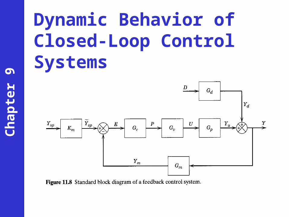
Dynamic Behavior of Closed-Loop Control Systems
Ch
apte
r 9
Control System Instrumentation
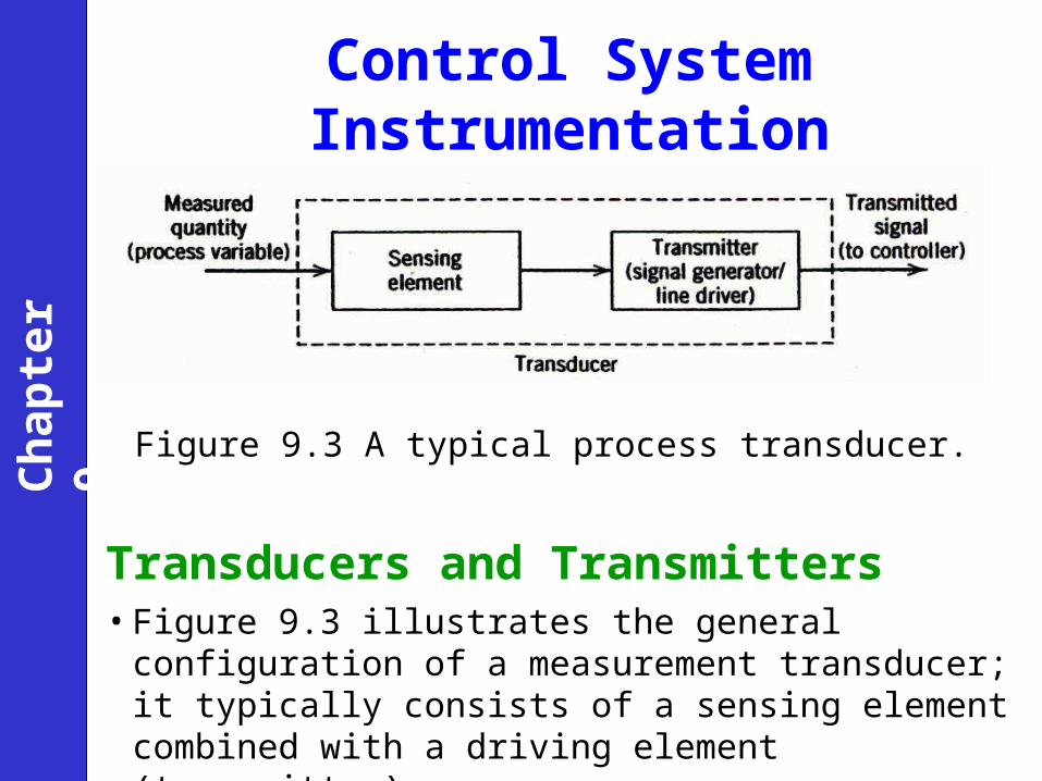
Figure 9.3 A typical process transducer.
Transducers and Transmitters• Figure 9.3 illustrates the general configuration of a
measurement transducer; it typically consists of a sensing element combined with a driving element (transmitter).
Ch
apte
r 9
• Since about 1960, electronic instrumentation has come into widespread use.
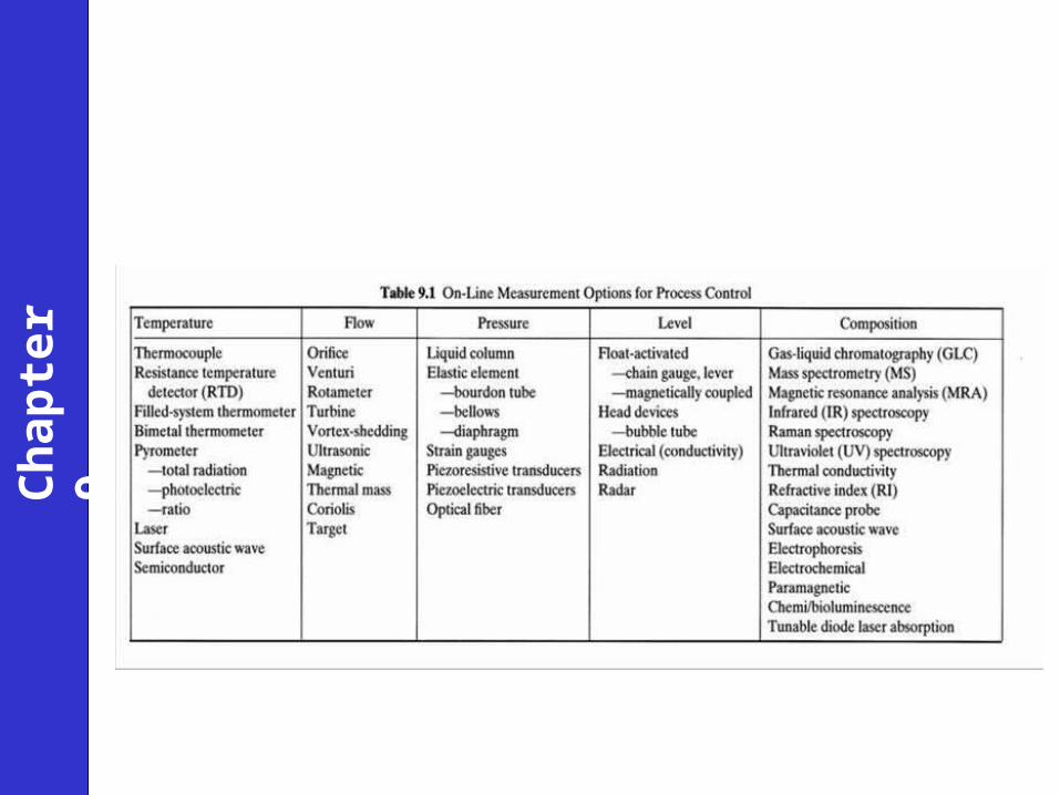
Sensors
The book briefly discusses commonly used sensors for the most important process variables. (See text.)
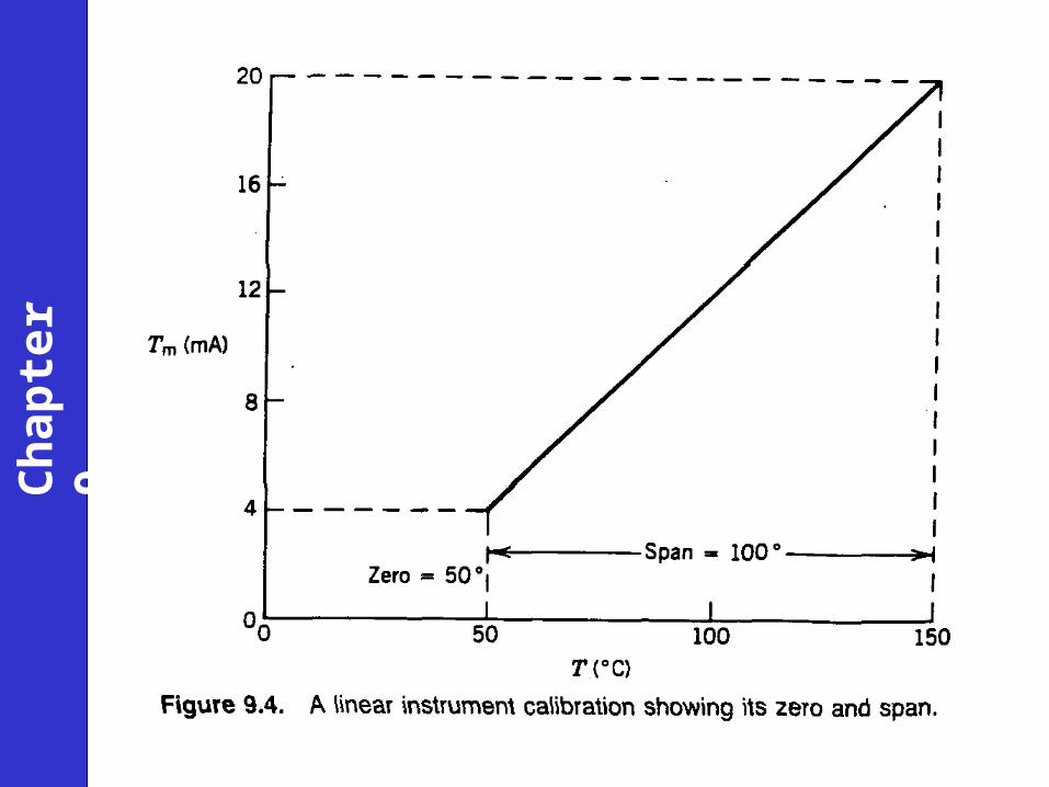
Transmitters• A transmitter usually converts the sensor output to a signal level
appropriate for input to a controller, such as 4 to 20 mA.
• Transmitters are generally designed to be direct acting.
• In addition, most commercial transmitters have an adjustable input range (or span).
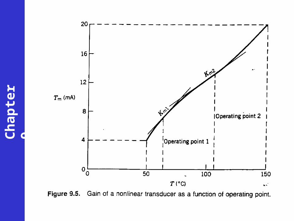
• For example, a temperature transmitter might be adjusted so that the input range of a platinum resistance element (the sensor) is 50 to 150 °C.
Ch
apte
r 9
Ch
apte
r 9
Ch
apte
r 9
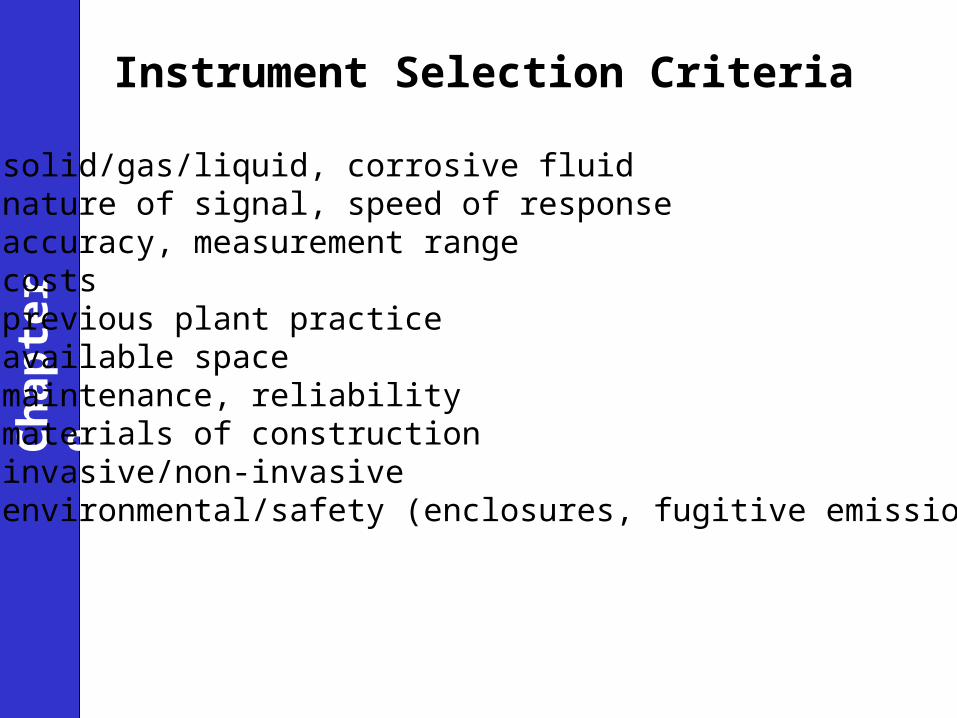
Instrument Selection Criteria
•solid/gas/liquid, corrosive fluid•nature of signal, speed of response•accuracy, measurement range•costs•previous plant practice•available space•maintenance, reliability•materials of construction•invasive/non-invasive•environmental/safety (enclosures, fugitive emissions)
Ch
apte
r 9
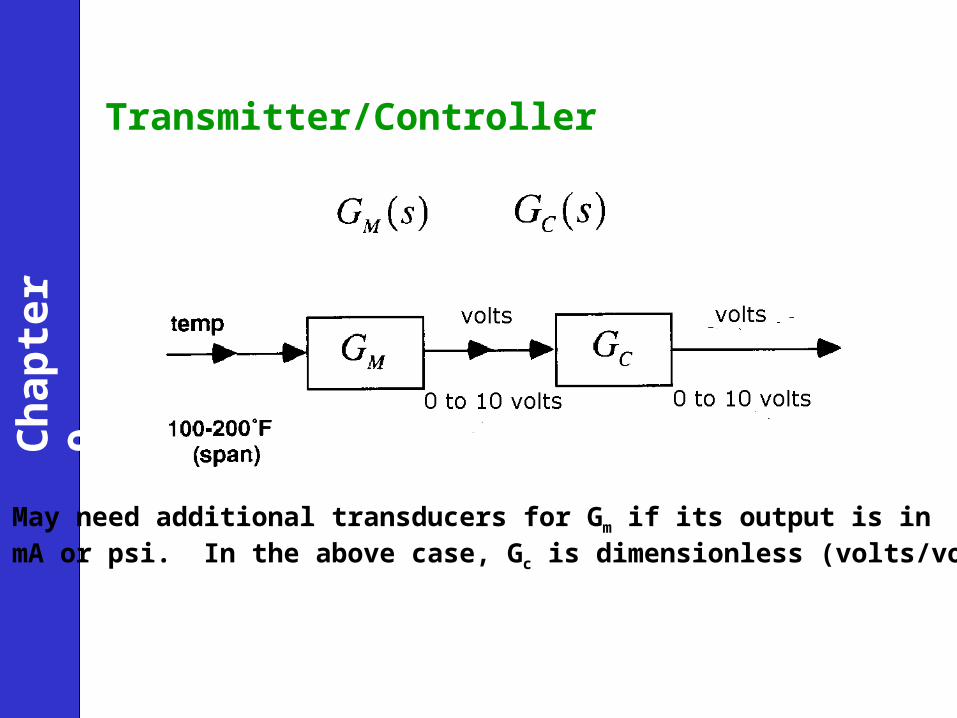
Transmitter/Controller
Ch
apte
r 9
May need additional transducers for Gm if its output is in mA or psi. In the above case, Gc is dimensionless (volts/volts).
Ch
apte
r 9
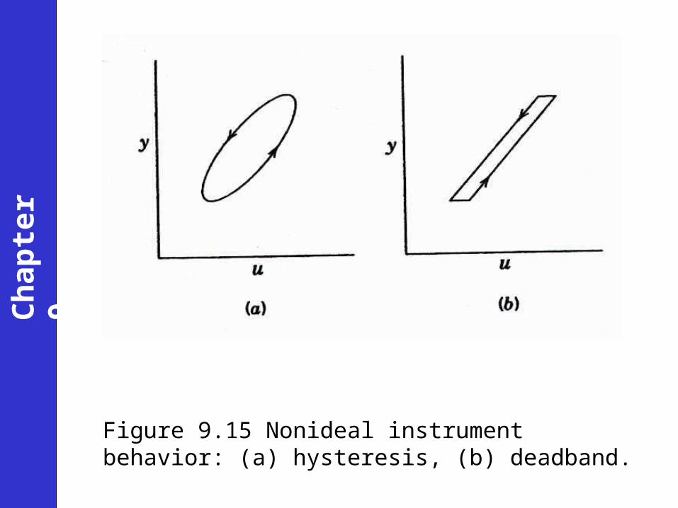
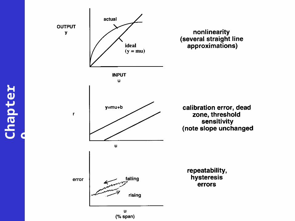
Figure 9.15 Nonideal instrument behavior: (a) hysteresis, (b) deadband.
Ch
apte
r 9
Ch
apte
r 9
Ch
apte
r 9
Ch
apte
r 9
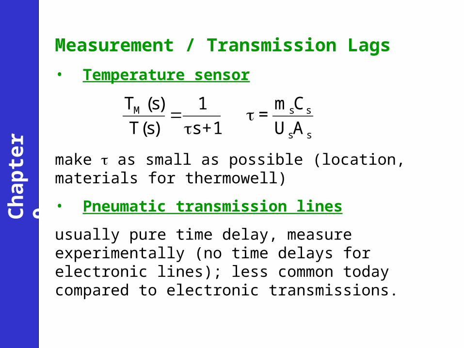
Measurement / Transmission Lags
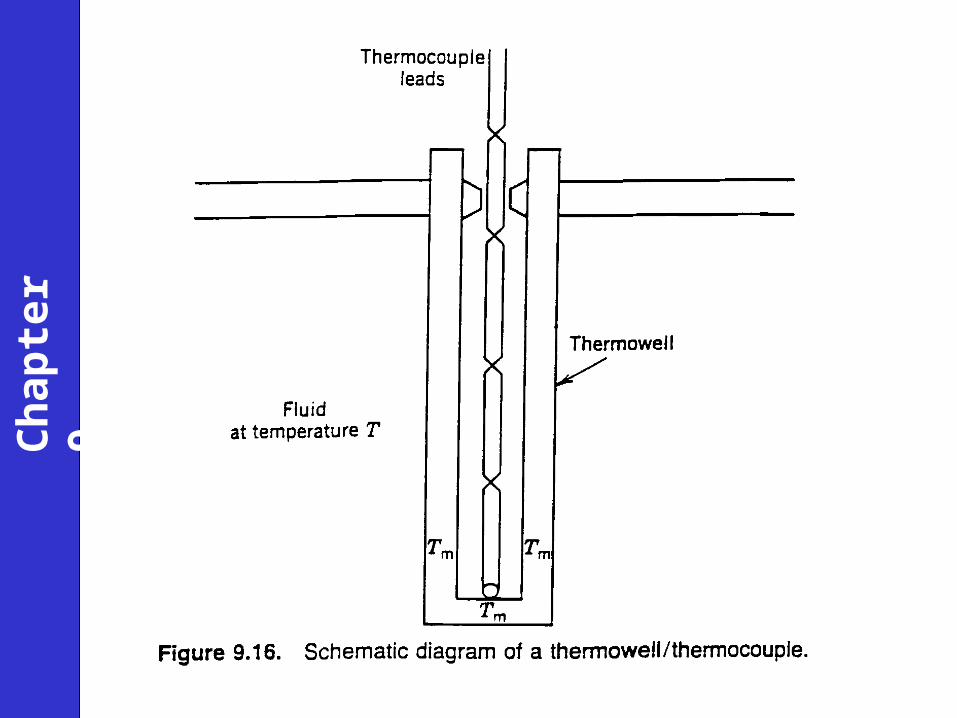
• Temperature sensor
make as small as possible (location, materials for thermowell)
• Pneumatic transmission lines
usually pure time delay, measure experimentally (no time delays for electronic lines); less common today compared to electronic transmissions.
ss
ssM
AU
Cm=
1+s
1
)s(T
)s(T
Ch
apte
r 9
Ch
apte
r 9
Ch
apte
r 9
Ch
apte
r 9
Ch
apte
r 9
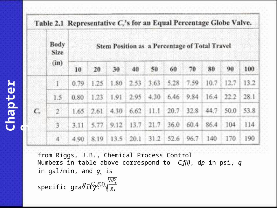
from Riggs, J.B., Chemical Process ControlNumbers in table above correspond to Cvf(l), dp in psi, q in gal/min, and gs is
specific gravity:
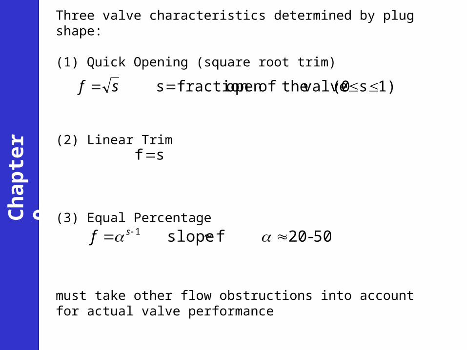
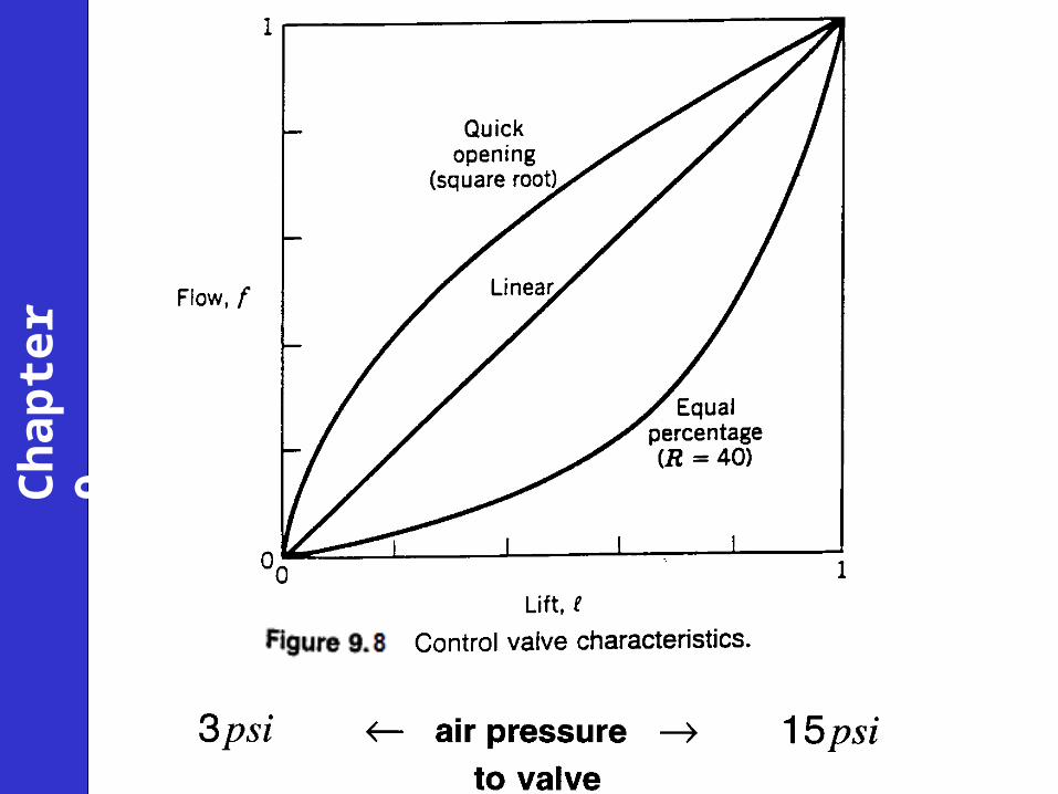
Three valve characteristics determined by plug shape:
(1) Quick Opening (square root trim)
(2) Linear Trim
(3) Equal Percentage
must take other flow obstructions into account for actual valve performance
1)s(0 valve theofopen fraction s sf
sf
50-20 f~slope 1 sf
Ch
apte
r 9

Ch
apte
r 9
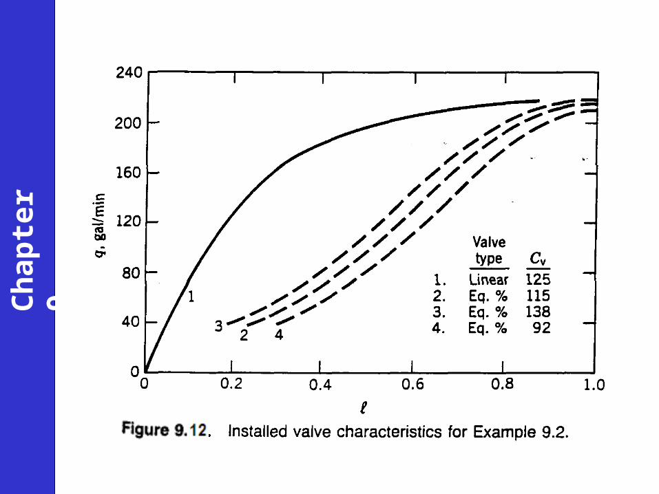
See Example 9.2
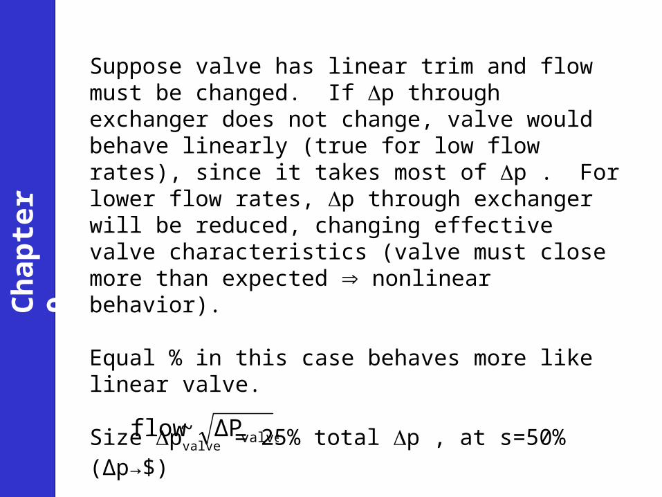
Suppose valve has linear trim and flow must be changed. If p through exchanger does not change, valve would behave linearly (true for low flow rates), since it takes most of p . For lower flow rates, p through exchanger will be reduced, changing effective valve characteristics (valve must close more than expected nonlinear behavior).
Equal % in this case behaves more like linear valve.
Size pvalve = 25% total p , at s=50% (Δp→$)
valves need to operate between 5% and 95%,
valveΔP~flow
Ch
apte
r 9
Ch
apte
r 9
Ch
apte
r 9
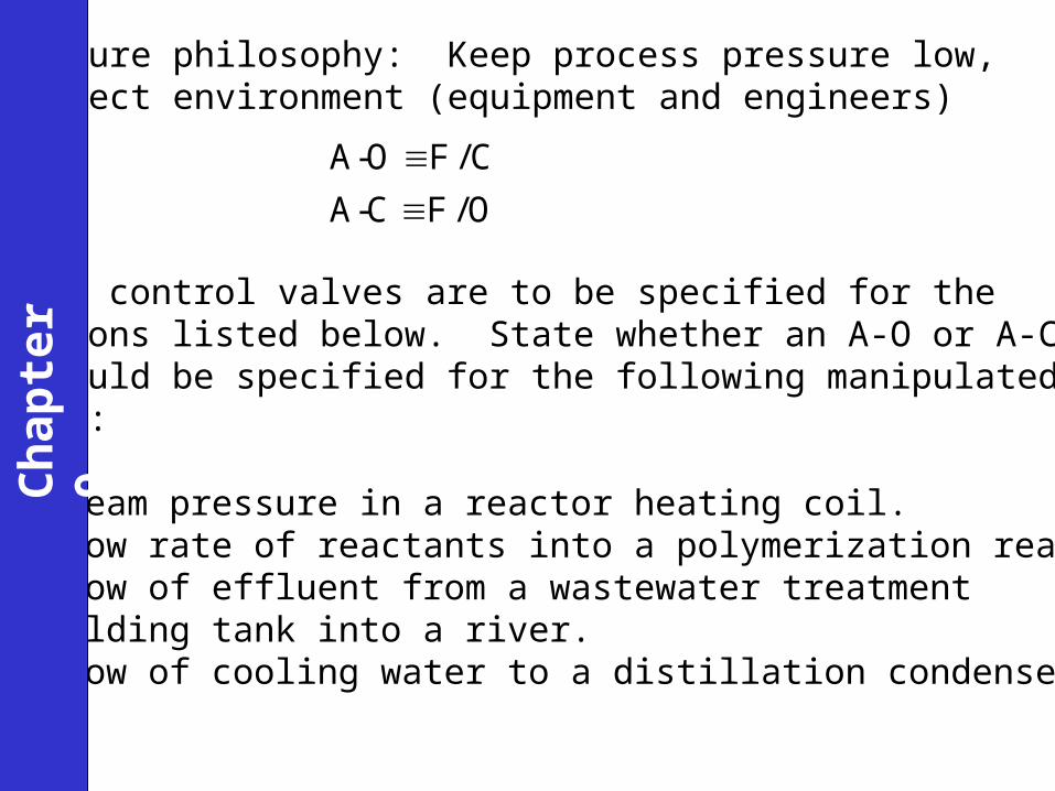
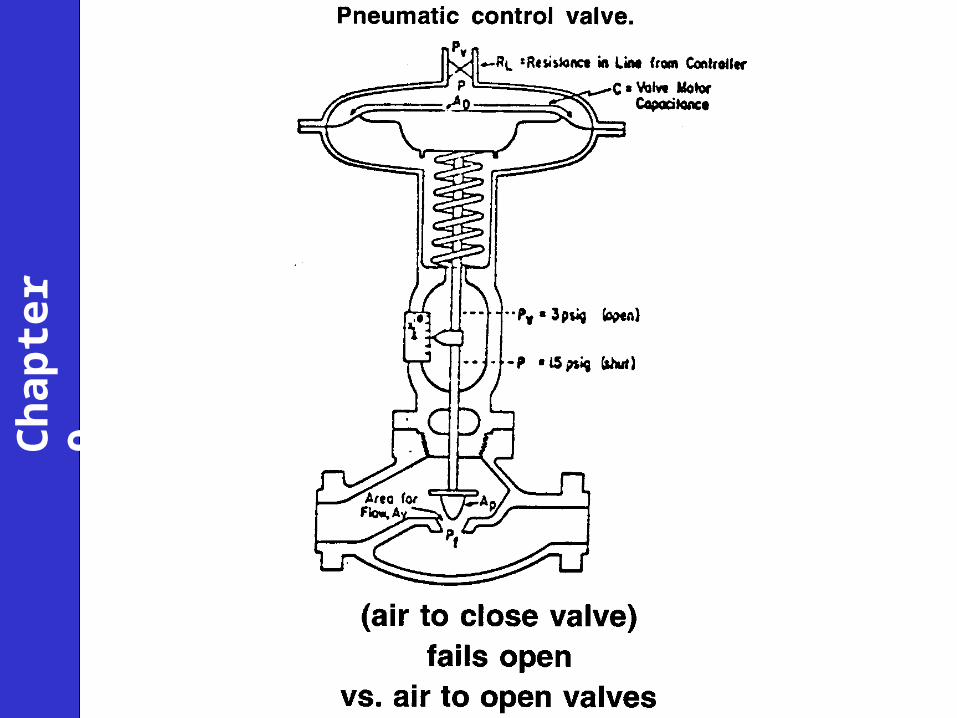
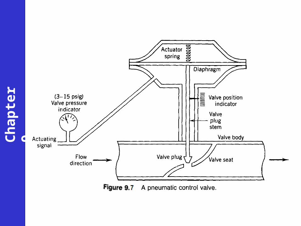
Pneumatic control valves are to be specified for theapplications listed below. State whether an A-O or A-Cvalve should be specified for the following manipulatedvariables:
(a) Steam pressure in a reactor heating coil.(b) Flow rate of reactants into a polymerization reactor.(c) Flow of effluent from a wastewater treatment
holding tank into a river.(d) Flow of cooling water to a distillation condenser.
Failure philosophy: Keep process pressure low,protect environment (equipment and engineers)
A-O F / C
A-C F / O
Ch
apte
r 9

Ch
apte
r 9
Previous chapter Next chapter
Related Documents