Progress In Electromagnetics Research C, Vol. 31, 153–168, 2012 DYNAMIC BASESTATION ANTENNA DESIGN FOR LOW ENERGY NETWORKS W. Guo * , J. M. Rigelsford, K. L. Ford, and T. O’Farrell Department of Electronic and Electrical Engineering, University of Sheffield, Mappin Street, Sheffield, S1 3JD, UK Abstract—A challenge faced by the information and communications technology (ICT) industry is the growing data volume and associated energy consumption. How to both meet a dynamic traffic demand at a consistently low energy consumption level is of importance from both commercial and climate change perspectives. This paper proposes a dynamic basestation concept that allows the number of active sectors to be adjusted in accordance with the traffic load. This is achieved through a novel switchable antenna design that can adjust the azimuth beam-width by using a tuneable reflector. Simulation and theoretical results show that the dynamic basestation can reduce the total operational energy of a cellular network by a peak of 75% and a mean of 38%. 1. INTRODUCTION Over the past 5years, the average communication data volume has increased by more than a factor of 10 and the associated energy consumption by at least 20%. Most of the wireless energy consumption is consumed by the outdoor cellular network’s basestations (70%). This energy consumption growth has had a negative impact on both the carbon footprint and the profit margin of the wireless ICT industry. Globally, mobile network operators (MNOs) contributes to 0.5% of carbon emissions. Commercially, approximately a third of the operational and maintenance (O&M) bill of MNOs is attributed to energy consumption. Therefore, there is an urgency to reduce energy consumption of basestations, whilst maintaining coverage and capacity. A promising solution to the challenge is to exploit the fact that mobile traffic is very dynamic, but the network coverage and capacity Received 15 June 2012, Accepted 9 July 2012, Scheduled 18 July 2012 * Corresponding author: Weisi Guo (w.guo@sheffield.ac.uk).

Welcome message from author
This document is posted to help you gain knowledge. Please leave a comment to let me know what you think about it! Share it to your friends and learn new things together.
Transcript
Progress In Electromagnetics Research C, Vol. 31, 153–168, 2012
DYNAMIC BASESTATION ANTENNA DESIGN FORLOW ENERGY NETWORKS
W. Guo*, J. M. Rigelsford, K. L. Ford, and T. O’Farrell
Department of Electronic and Electrical Engineering, University ofSheffield, Mappin Street, Sheffield, S1 3JD, UK
Abstract—A challenge faced by the information and communicationstechnology (ICT) industry is the growing data volume and associatedenergy consumption. How to both meet a dynamic traffic demandat a consistently low energy consumption level is of importance fromboth commercial and climate change perspectives. This paper proposesa dynamic basestation concept that allows the number of activesectors to be adjusted in accordance with the traffic load. This isachieved through a novel switchable antenna design that can adjustthe azimuth beam-width by using a tuneable reflector. Simulation andtheoretical results show that the dynamic basestation can reduce thetotal operational energy of a cellular network by a peak of 75% and amean of 38%.
1. INTRODUCTION
Over the past 5 years, the average communication data volume hasincreased by more than a factor of 10 and the associated energyconsumption by at least 20%. Most of the wireless energy consumptionis consumed by the outdoor cellular network’s basestations (70%).This energy consumption growth has had a negative impact on boththe carbon footprint and the profit margin of the wireless ICTindustry. Globally, mobile network operators (MNOs) contributes to0.5% of carbon emissions. Commercially, approximately a third of theoperational and maintenance (O&M) bill of MNOs is attributed toenergy consumption. Therefore, there is an urgency to reduce energyconsumption of basestations, whilst maintaining coverage and capacity.
A promising solution to the challenge is to exploit the fact thatmobile traffic is very dynamic, but the network coverage and capacity
Received 15 June 2012, Accepted 9 July 2012, Scheduled 18 July 2012* Corresponding author: Weisi Guo ([email protected]).

154 Guo et al.
is very static. By adapting the coverage and capacity in accordance tothe traffic environment, significant energy can be saved [1].
A key consideration of basestation (BS) design is to maximizespectrum reuse. This is achieved by sectorization, so that a BSconsists of multiple sectors with directional antennas. The azimuthbeamwidth of the antennas pre-dominantly depends on the number ofsectors. Generally speaking, the amount of bandwidth and the powerconsumption at the BS scales linearly with the number of sectors [2].Typically, a network consisting of multiple BSs is deployed to meetan offered peak traffic rate [3]. In the temporal domain, the trafficintensity typically varies by 4 to 6 folds during the course of a day. Inthe spatial domain, the traffic intensity between BSs can vary by upto 10 folds.
The challenge addressed in this paper is how to design a dynamicBS that can meet the peak traffic demand, but consume the minimumamount of energy across the variations. The system level energy andcapacity performance of this proposed BS is analyzed in the context ofa multi-cell multi-user simulator.
1.1. Existing Techniques
Existing literature has proposed a variety of energy efficient techniques,which can be categorized into the following:
• Offloading : offloading a certain proportion of the data from highenergy BSs to low energy nodes, i.e., from macro-BSs to relays [4].The advantage of this technique is that the coverage pattern of thenetwork has not changed dramatically, but the energy saved is notdramatic due to the fact that all existing infrastructure remainsactive and additional nodes are inserted [5].
• Sleep Mode: switch-off certain BSs that experience a low trafficdemand [1]. The advantage of this technique is that byswitching-off infrastructure, a significant amount of energy issaved. However, coordinating which BSs to switch-off, as wellas predicting the subsequent coverage pattern is challenging.
In order to maximize the performance of the aforementionedtechniques, generally some level of re-deployment of BSs and inter-node coordination is needed [6]. For cost reasons, there is a reluctancyfor MNOs to implement extensive inter-BS coordination interfaces or tore-deploy the network. Therefore, a pragmatic energy-efficient solutionmust incorporate the following features:
(i) Scalability: significantly reduce energy consumption with loweroffered traffic rate.
Progress In Electromagnetics Research C, Vol. 31, 2012 155
(ii) Reliability: not incur unexpected coverage changes and causeoutages.
(iii) Pragmatic: does not require inter-BS coordination, network-wide control, or the installation of new network elements.
In order to achieve this, dynamic BS design and its application hasbeen proposed before in various forms on a system level [7–9] and onan antenna design level [10–12].
To date, adaptive antennas for cellular networks have includeddesigns for dual-band operation where the frequency band ofoperation can be electronically switched [13, 14] and designs whichcan be switched between omni-directional and sectorized radiationpatterns [12, 15, 16]. The designs proposed in [15, 16] comprises high-gain collinear antenna surrounded by an active cylindrical frequencyselective surface (FSS). By electronically controlling the state of theFSS a directive radiation pattern can be obtained that can be swept inthe entire azimuth plane, or if the FSS is switched off omni-directionalcoverage can be provided. The disadvantage of this design and similardesigns is that that resultant BS is capacity-limited as all users sharethe same RF feed regardless of the configuration.
1.2. Proposed Solution
One promising concept that can efficiently scale energy consumptionwith the traffic load, is to allow the BS to dynamically switch between:
• High Capacity-High Energy: multiple directional sectors, duringperiods of high traffic.
• Low Capacity-Low Energy: single omni-directional sector, duringperiods of low traffic.
Given that the offered traffic varies in time and space, a scalableradio-access-network (RAN) should consist of multiple BSs that havedifferent number of sectors, that can change in accordance with thetraffic environment. Each BS only needs to be aware of its own trafficload and does not need knowledge on the state of neighbouring BSs.Furthermore, no additional infrastructure or network-wide controller isrequired in the network. The antenna design itself doesn’t save energy,but it enables the BSs to dynamically sleep and wake its sectors. Thetwo primary BS designs considered in this paper are:
• Reference BS: 6-sector BS that maintains all the sectors asactive across all traffic variations. The transmission energyconsumption is scaled linearly with the offered traffic.

156 Guo et al.
(a) (b) (c)
Figure 1. Dynamic BS’s operational modes (top) and mean receivedSINR plots (bottom) across different traffic loads: (a) 6 sectors, (b) 3sectors, (c) 1 sector.
• Dynamic BS: 6-sector BS that dynamically switches-off itssectors and adapts the antenna beam pattern in accordance, asshown in Figure 1.
In order to achieve this, the BS has to either switch between differentantenna types or employ an adaptive antenna that can change its beampattern.
Whilst this idea has been proposed before on a system-level [8, 9]and antenna-level [15, 16], to the best of our knowledge no joint-consideration in terms of energy-efficiency has been considered.Furthermore the proposed antenna design is novel and has the followingbenefits over existing designs:
• increased coverage due to adaptive beam-forming and gain control.To date, research has predominantly focused on the control of the

Progress In Electromagnetics Research C, Vol. 31, 2012 157
elevation beamwidth and electrical down-tilt of antenna systems.This can be achieved by traditional amplitude and phase controlof the antenna array [11, 17] or using time modulated linear arrays(TMLAs) where the main beam direction is controlled by alteringthe switch-on time sequence of each element in the array [18];
• lower transmit power requirements due to optimized transmissiontowards the user. This can include aspects of elevation beamwidthoptimization but also azimuth beamwidth control for micro- orpico-BSs [19, 20];
• improved link quality due to spatial or polarization diversitygain. Presently, cellular RANs combine spatial diversity betweenBSs, and polarization diversity within a BS. Many examples ofsuitable antennas are available in the literature [21–23]. Currentresearch focus is towards multiple-input multiple-output (MIMO)communication techniques which make use of multi-elementantenna arrays at both the transmitter and the receiver of a radiolink. MIMO has been theoretically shown to drastically improvethe capacity over more traditional single-input single-output(SISO) or single-input multiple-output (SIMO) systems [24].
The paper’s system and antenna integrated study considers multi-BSinterference and total energy consumption. This paper demonstratesthat the proposed adaptive antenna design is simple and significantenergy can be saved compared to a reference BS design. The paperpresents the dynamic BS design in Section 2 and how it incorporatesinto the network in Section 3. The theoretical relationship betweentraffic load and energy consumption, as well as theoretical boundsis shown in Section 4. The results for the energy saved is shown inSection 5.
2. DYNAMIC BS DESIGN
2.1. Reconfigurable Antenna Concept
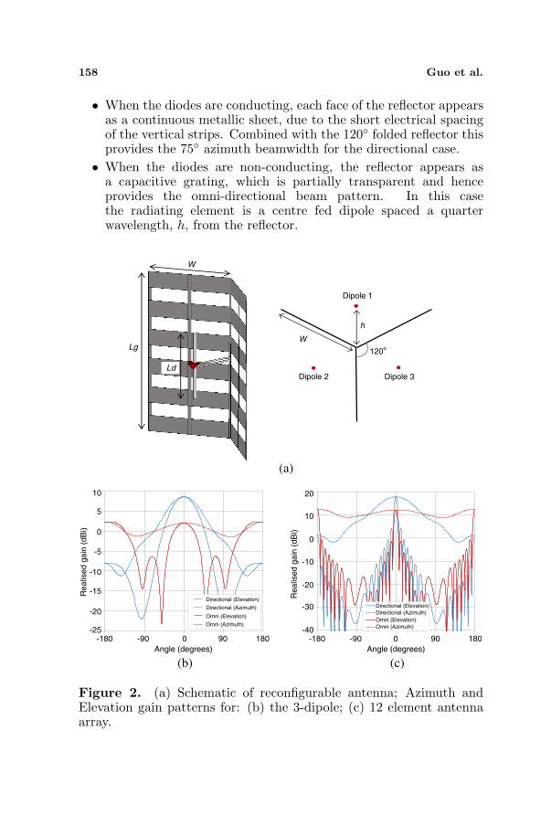
The schematic for a reconfigurable directional to omni-directionalantenna system is presented in Figure 2(a). This particular design isfor a 3-sector to a 1-sector BS, which can be extended to multi-sectorssuch as that envisage in Figure 1. The design uses a combination ofa radiating dipole and a folded reflector to provide the required beamreconfigurability. The reflector considered comprises of an array of 6horizontal metallic strips of length, w, with three vertical strips equallyspaced across each half of the reflector. The vertical strips provide thereconfigurability via an array of PIN diodes connected in series withthe vertical strips:
158 Guo et al.
• When the diodes are conducting, each face of the reflector appearsas a continuous metallic sheet, due to the short electrical spacingof the vertical strips. Combined with the 120 folded reflector thisprovides the 75 azimuth beamwidth for the directional case.
• When the diodes are non-conducting, the reflector appears asa capacitive grating, which is partially transparent and henceprovides the omni-directional beam pattern. In this casethe radiating element is a centre fed dipole spaced a quarterwavelength, h, from the reflector.
(a)
(b) (c)
W
Lg
LdDipole 2
120
h
W
Dipole 1
Dipole 3
o
-180 -90 0 90 180
Angle (degrees)
-180 -90 0 90 180
Angle (degrees)
10
5
0
-5
-10
-15
-20
-25
Re
alis
ed
ga
in (
dB
i)
20
10
0
-10
-20
-30
-40
Re
alis
ed
ga
in (
dB
i)
Directional (Elevation)
Directional (Azimuth)
Omni (Elevation)
Omni (Azimuth)
Directional (Elevation)
Directional (Azimuth)
Omni (Elevation)
Omni (Azimuth)
Figure 2. (a) Schematic of reconfigurable antenna; Azimuth andElevation gain patterns for: (b) the 3-dipole; (c) 12 element antennaarray.
Progress In Electromagnetics Research C, Vol. 31, 2012 159
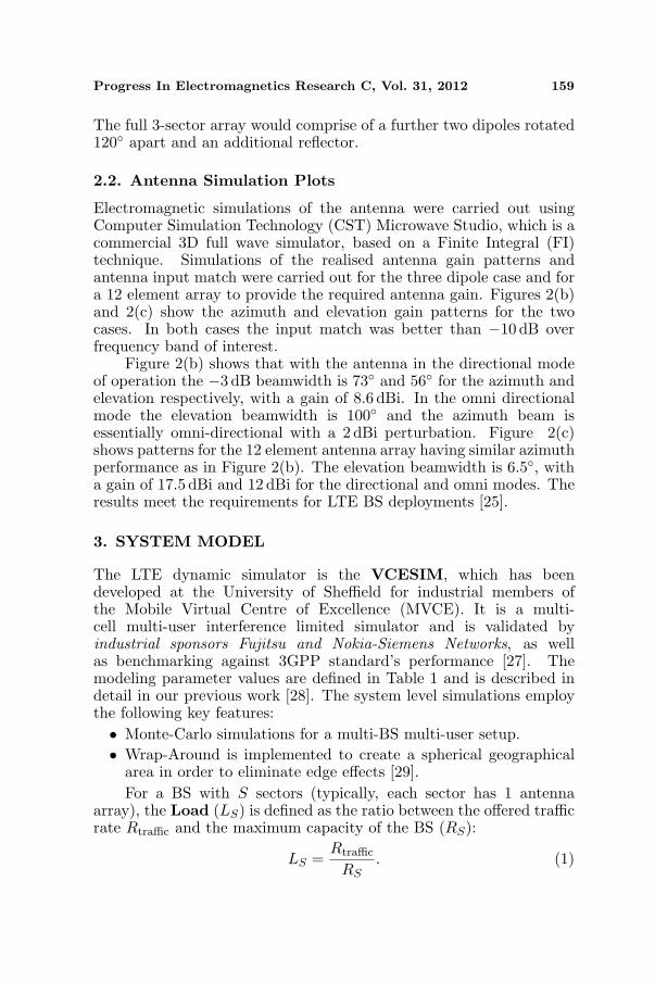
The full 3-sector array would comprise of a further two dipoles rotated120 apart and an additional reflector.
2.2. Antenna Simulation Plots
Electromagnetic simulations of the antenna were carried out usingComputer Simulation Technology (CST) Microwave Studio, which is acommercial 3D full wave simulator, based on a Finite Integral (FI)technique. Simulations of the realised antenna gain patterns andantenna input match were carried out for the three dipole case and fora 12 element array to provide the required antenna gain. Figures 2(b)and 2(c) show the azimuth and elevation gain patterns for the twocases. In both cases the input match was better than −10 dB overfrequency band of interest.
Figure 2(b) shows that with the antenna in the directional modeof operation the −3 dB beamwidth is 73 and 56 for the azimuth andelevation respectively, with a gain of 8.6 dBi. In the omni directionalmode the elevation beamwidth is 100 and the azimuth beam isessentially omni-directional with a 2 dBi perturbation. Figure 2(c)shows patterns for the 12 element antenna array having similar azimuthperformance as in Figure 2(b). The elevation beamwidth is 6.5, witha gain of 17.5 dBi and 12 dBi for the directional and omni modes. Theresults meet the requirements for LTE BS deployments [25].
3. SYSTEM MODEL
The LTE dynamic simulator is the VCESIM, which has beendeveloped at the University of Sheffield for industrial members ofthe Mobile Virtual Centre of Excellence (MVCE). It is a multi-cell multi-user interference limited simulator and is validated byindustrial sponsors Fujitsu and Nokia-Siemens Networks, as wellas benchmarking against 3GPP standard’s performance [27]. Themodeling parameter values are defined in Table 1 and is described indetail in our previous work [28]. The system level simulations employthe following key features:• Monte-Carlo simulations for a multi-BS multi-user setup.• Wrap-Around is implemented to create a spherical geographical
area in order to eliminate edge effects [29].For a BS with S sectors (typically, each sector has 1 antenna
array), the Load (LS) is defined as the ratio between the offered trafficrate Rtraffic and the maximum capacity of the BS (RS):
LS =Rtraffic
RS. (1)

160 Guo et al.
Table 1. System and hardware parameters.
Parameter Symbol Value
System Parameters
LTE Operating Frequency f 2600MHz
Number of BSs in RAN NBS 19
Interference Model 19 BS Wrap Around
Propagation Model λ WINNER II [25]
Antenna Pattern A(θ) Figure 2
AWGN Power per Subcarrier N0 6× 10⁻¹⁷ W
Shadow Fading Variance σ2s 9 dB
Transmission Scheme SISO
Traffic Load Rtraffic 0–120Mbit/s/km2 [26]
Hardware Parameters
BS Coverage Radius rBS 200–1500m
BS Transmit Power P 5–40W
Radiohead Efficiency µ 0.2–0.3
Overhead Power POH 25–95W
Backhaul Power PBH 50W
Radiohead Proportion Ω 0.32–0.58
Sleep Mode Overhead Factor η 0–1
A general model for the total operational power consumption PBS fora BS can be broken down into a load dependent and independentparts [28]:
PBS = S
(P
µLS + POH
)+ PBH ≈ S
(0.1rBSLS + r0.62
BS
)+ 50, (2)
where each parameter and its typical values are defined in Table 1.The load dependent aspect of the expression is known as the radio-head (RH): PRH = P
µ LS and the load independent is known as theoverhead and backhaul (POH+PBH). This expression can be expressedas a function of the BS coverage radius (rBS), by using a curve-fittingapproach on the empirical data from [2]. The fitting is accurate, asshown in Figure 3. The benefit of the modified expression is that thereis now a relationship between BS coverage range (BS density) andpower consumption.
When the sector of a BS is switched off and no-longer transmitting,the paper assumes the overhead power consumption associated withthat sector remains at a faction η of the full value. The paper willconsider the resulting gains that arise from different values of η, which

Progress In Electromagnetics Research C, Vol. 31, 2012 161
Figure 3. Power consumption per Sector’s variation with BS coveragesize: Data (symbols) from [2] and theory (line) from expression 2.
typically vary between 0 to 40% [26, 30].
4. ENERGY SAVING BOUNDS
4.1. Reference Bound
The paper defines the energy reduction gain (ERG) as amount ofenergy saved by a test setup in comparison with a reference setup.The paper first considers the maximum amount of energy that can besaved by the reference BS, as the offered traffic load (L) varies. TheERG achieved in comparison with peak load is
ERGRef. = 1− PBS(L = 1)PBS(L)
= (1− L)Ω,
where: Ω =Pµ
PBS,
(3)
where for L → 0, the energy saving approaches Ω = 30–50%,depending on the BS technology (expression 2). Therefore, the energysaving gain relative to the peak consumption value is hardware-limitedby the ratio between load dependent (radio-head) and total powerconsumption of the BS.
162 Guo et al.
Table 2. Dynamic BS performance.
Sectors (S) BS Capacity (RS) Capacity per Sector Ψ
6 R6 = 52Mbit/s 8.7Mbit/s 1
3 R3 = 41Mbit/s 13.7Mbit/s 0.64
1 R1 = 28Mbit/s 28.7Mbit/s 0.30
4.2. Dynamic Antenna Reduction Bound
The paper now considers the technique of antenna/sector reduction.Consider a dynamic BS with initially S sectors that yield a BS capacityof RS , and a resultant load LS , as defined in expression 1. Each stageof reduction to S′ sectors also reduces the BS capacity to RS′ . Theresulting load (LS′) on the new BS configuration is:
LS′ =Rtraffic
RS′= LS
RS
RS′. (4)
The ERG achieved relative to a peak load power consumption is:
ERGDynamic = 1− PBS(L = 1, S)PBS(LS′ , S′)
= (1−ΨLS)Ω +S − S′
S(1− η)(1− Ω)
where: Ψ =S′RS
SRS′=
(RS/S)(RS′/S′)
.
(5)
The factor Ψ is effectively the ratio between the capacity per sectorbetween a BS with S sectors and a BS with S′ sectors. A low ratio(Ψ < 1) would mean that the loss in capacity per BS is low and thereis in fact a gain in capacity per sector. The ERG is improved whenthe value of η is small.
For the considered case of a dynamic BS switching from S = 6 toS′ = 3 to S′ = 1 sectors, simulation has found the BS capacity andΨ parameter for different number of sectors and they are presented inTable 2. The decision to switch between sector configurations is basedon whether the new configuration’s capacity can satisfy the offeredtraffic load. For an optimistic value of η = 0, the resulting ERGcompared to peak load at each stage is:ERGDynamic = (1− LS)Ω for: Rtraffic > RS′=3
= (1− 0.64LS)Ω + 12(1− Ω) for: Rtraffic > RS′=1
= (1− 0.30LS)Ω + 56(1− Ω) for: Rtraffic < RS′=1.
(6)
The bound approaches:
ERGDynamic → Ω +S − S′
S(1− Ω), (7)
Progress In Electromagnetics Research C, Vol. 31, 2012 163
which is 88–91% for L → 0, S = 6, S′ = 1, η = 0 and Ω = 0.3to 0.5 (BS size and technology dependent). This is an improvementover the reference BS energy savings given in 3, which was limitedby Ω = 30–50%. For a given load, the ERG is amplified by a lowΨ and a high Ω value. A low Ψ value results from achieving thegreatest capacity with the lowest number of sectors active. A largeΩ results from BSs that have a greater proportion of load dependentpower consumption (typically large macro-BSs, as shown in Figure 3).
4.3. Summary
The most energy efficient dynamic BS design has the followingproperties:
• Scalability: reducing the number of sectors doesn’t result in asevere loss in capacity (Ψ).
• Low Overhead: most of the power consumption of the BS isload dependent (Ω).
The scalability can be achieved with a strong omni-directional antennadesign and the low-overhead can be achieved by reducing the powerconsumption of cooling and signal-processing units. When comparingthe energy consumption of the dynamic and reference BSs, the ERGbound approaches S−S′
S for η = 0 and LS′ = 0. The precise loaddependent energy saving of the dynamic BS compared to the referenceBS is examined in the next section’s multi-cell RAN results.
5. RESULTS
5.1. Traffic Variation
The paper now considers how the power consumption value changes foreach BS as the offered traffic varies. The results presented in Figure 4are obtained using both theoretical expressions (lines) and accuratesystem simulation results (symbols). The model considers macro-BSswith a hardware factor of Ω = 0.5 [2] and various values of the sleep-mode parameter η.
In comparison with the reference BS, the mean upper-boundenergy saving of 44% (η = 0) and the lower-bound saving is 11%(η = 1). Furthermore, a larger (Ω) value will amplify the ERGimprovements. It can be seen that for every η value, the energy savedis equal or greater than the reference system, for any offered trafficrate.

164 Guo et al.
Figure 4. Power consumption variation with traffic load and η for amacro-BS (rBS = 1500 m, Ω = 0.5). Simulation (symbols) and theory(lines).
5.2. Urban Traffic Model
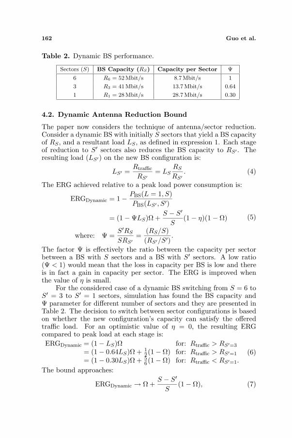
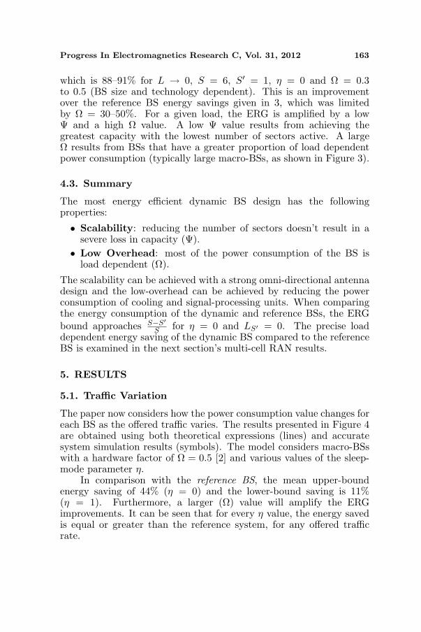
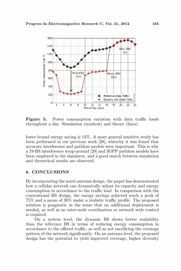
The paper now considers how the traffic rate actually varies acrossthe duration of a day. The typical data traffic intensity of aEuropean urban area is dominated by long periods of low load(night and mornings) and short periods of peak traffic load (day andevenings) [26].
The results in Figure 5 show that the greatest energy saving isachieved at the lowest load times, which typically occur during theearly hours of the morning (3–7 am), with an energy saving of 75%compared to reference. During the evening, the network is typicallyoperating at full buffer and the associated energy saving compared toreference is none. Under the urban data traffic loads, the mean energysaving achieved is 38%.
It is worth noting that the multi-cell multi-user simulator considersa uniform but random distribution of traffic load. This means that atany particular instance, the BS are not all performing with the sameoperational mode (number of sectors active). In terms of sensitivityanalysis, the underlying assumption is that when a sector is switchedoff, all or most of the overhead consumption can be switched off (η ∼ 0).The lower bound of the energy savings is when η = 1 and the mean
Progress In Electromagnetics Research C, Vol. 31, 2012 165
Figure 5. Power consumption variation with data traffic loadsthroughout a day. Simulation (symbols) and theory (lines).
lower-bound energy saving is 13%. A more general sensitive study hasbeen performed in our previous work [28], whereby it was found thataccurate interference and pathloss models were important. This is whya 19-BS interference wrap-around [29] and 3GPP pathloss models havebeen employed in the simulator, and a good match between simulationand theoretical results are observed.
6. CONCLUSIONS
By incorporating the novel antenna design, the paper has demonstratedhow a cellular network can dynamically adjust its capacity and energyconsumption in accordance to the traffic load. In comparison with theconventional BS design, the energy savings achieved reach a peak of75% and a mean of 38% under a realistic traffic profile. The proposedsolution is pragmatic in the sense that no additional deployment isneeded, as well as no inter-node coordination or network wide controlis required.
On a system level, the dynamic BS shows better scalabilitythan the reference BS in terms of reducing energy consumption inaccordance to the offered traffic, as well as not sacrificing the coveragepattern of the network significantly. On an antenna level, the proposeddesign has the potential to yield improved coverage, higher diversity
166 Guo et al.
and lower transmit power; when compared to existing dynamic antennadesigns.
The paper has shown that an integrated system-and-antennadesign has resulted in significant operational energy savings, which hasa high impact on the future deployment of energy- and cost-efficientmobile communications.
ACKNOWLEDGMENT
The work papered in this paper has formed part of the Green RadioResearch Programme of the Virtual Centre of Excellence in Mobileand Personal Communications, Mobile VCE. Fully detailed technicalpapers are available to Industrial Members of the Mobile VCE.www.mobilevce.com.
REFERENCES
1. Niu, Z., Y. Wu, J. Gong, and Z. Yang, “Cell zooming forcost-efficient green cellular networks,” IEEE CommunicationsMagazine, 74–79, Nov. 2010.
2. Auer, G., V. Giannini, I. Godor, P. Skillermark, M. Olsson, M. Im-ran, D. Sabella, M. Gonzalez, C. Desset, and O. Blume, “Cellularenergy efficiency evaluation framework,” IEEE Vehicular Technol-ogy Conference, VTC Spring, 1–6, May 2011.
3. Xiong, C., G. Li, S. Zhang, Y. Chen, and S. Xu, “Energy- andspectral-efficiency tradeoff in downlink OFDMA networks,” IEEETransactions on Wireless Communications, Vol. 10, No. 11, 3874–3885, Nov. 2011.
4. Guo, W. and T. O’Farrell, “Relay deployment in cellular networks:Planning and optimization,” IEEE Journal on Selected Areas inCommunications (JSAC), Sep. 2012.
5. Khirallah, C. and J. Thompson, “Energy and cost impactof relay and femtocell deployments in LTE-advanced,” IETCommunication, Vol. 5, 2617–2628, Dec. 2011.
6. Guo, W. and T. O’Farrell, “Small-net vs. relays in a heterogeneousarchitecture,” Journal of Communications, JCM, 2012.
7. Paulraj, R. N. A. and D. Gore, Introduction to Space-timeWireless Communications, Cambridge University Press, UK,2003.
8. Holland, O., V. Friderikos, and A. H. Aghvami, “Energy efficientcross band spectrum management for mobile operators,” Proc.IEEE Globecom, 2020–2040, Dec. 2010.
Progress In Electromagnetics Research C, Vol. 31, 2012 167
9. Christofferson, J., “Energy efficiency by cell reconfiguration:MIMO to non-MIMO and 3-cell sites to omni,” Green WirelessCommunications and Networks Workshop, GreenNet, May 2010.
10. Alexiou, A. and M. Haardt, “Smart antenna technologiesfor future wireless systems: Trends and challenges,” IEEECommunications Magazine, Vol. 42, 90–97, Sep. 2004.
11. Benedetti, M., G. Oliveri, P. Rocca, and A. Massa, “A fully-adaptive smart antenna prototype: Ideal model and experimentalvalidation in complex interference scenarios,” Progress InElectromagnetics Research, Vol. 96, 173–191, 2009.
12. Martinez-Lorenzo, J., M. Arias, O. Rubinos, J. Gutierrez, andA. Garcia-Pino, “A shaped and reconfigurable reflector antennawith sectorial beams for LMDS base station,” IEEE Transactionson Antennas and Propagation, Vol. 54, 1346–1349, Apr. 2006.
13. Jung, Y. B., “Dual-band reconfigurable antenna for base-stationapplications,” Electronics Letters, Vol. 46, 195–196, Feb. 2010.
14. Cai, Y., Y. Guo, and P.-Y. Qin, “Frequency switchable printedyagi-uda dipole sub-array for base station antennas,” IEEETransactions on Antennas and Propagation, Vol. 60, 1639–1642,Mar. 2012.
15. Edalati, A. and T. A. Denidni, “Reconfigurable beamwidthantenna based on active partially reflective surfaces,” IEEEAntennas and Wireless Propagation Letters, Vol. 8, 1087–1090,2009.
16. Edalati, A., “High-gain reconfigurable sectoral antenna using anactive cylindrical FSS structure,” IEEE Transactions on Antennasand Propagation, Vol. 59, 2464–2472, 2011.
17. 3GPP, “TS 25.463: UTRAN iuant interface: Remote electricaltilting (RET) antennas application part (RETAP) signalling(Release 6),” 3GPP, Technical Report, Dec. 2007.
18. Li, G., S. Yang, Y. Chen, and Z.-P. Nie, “A novel electronic beamsteering technique in time modulated antenna arrays,” ProgressIn Electromagnetics Research, Vol. 97, 391–405, 2009.
19. Ford, K. L. and J. M. Rigelsford, “Street furniture antenna radia-tion pattern control using AMC surfaces,” IEEE Transactions onAntennas and Propagation, Vol. 56, 3049–3052, 2008.
20. Rigelsford, J. M., J. M. Collado, and K. L. Ford, “Radiationsteering of a low profile street furniture antenna using an activeAMC,” Antennas and Propagation Conference, LAPC, 529–532,Loughborough, 2010.
21. Moradi, K. and S. Nikmehr, “A dual-band dual-polarized
168 Guo et al.
microstrip array antenna for base stations,” Progress InElectromagnetics Research, Vol. 123, 527–541, 2012.
22. Perikos, G. and J. M. Rigelsford, “An 8 element broadbandantenna for AMPS and GSM applications,” Proceedings ofthe Fourth European Conference on Antennas and Propagation,EuCAP, 1–3, Apr. 2010.
23. Peng, H.-L., W.-Y. Yin, J.-F. Mao, D. Huo, X. Hang, andL. Zhou, “A compact dual-polarized broadband antenna withhybrid beam-forming capabilities,” Progress In ElectromagneticsResearch, Vol. 118, 253–271, 2011.
24. Gesbert, D., H. Bolcskei, D. Gore, and A. Paulraj, “MIMOwireless channels: Capacity and performance prediction,” IEEEGlobal Telecommunications Conference 2000, GLOBECOM’00,1083–1088, 2000.
25. 3GPP, “TR36.814 V9.0.0: Further advancements for E-UTRAphysical layer aspects (Release 9),” 3GPP, Technical Report,Mar. 2010.
26. EARTH, “WP2.D2.3: Energy efficiency analysis of the referencesystems,” Energy Aware Radio and Network Technologies(EARTH), Technical Report, Dec. 2010.
27. Ericsson, “Summary of downlink performance evaluation,” 3GPPTSG RAN R1-072444, Technical Report, May 2007.
28. Guo, W. and T. O’Farrell, “Green cellular network: Deploymentsolutions, sensitivity and tradeoffs,” IEEE Proc. WirelessAdvanced (WiAd), London, UK, Jun. 2011.
29. Dinnis, A. and J. Thompson, “The effects of including wraparoundwhen simulating cellular wireless systems with relaying,” IEEEVehicular Technology Conference, 914–918, Apr. 2007.
30. Hedayati, M., M. Amirijoo, P. Frenger, and J. Moe, “Reducingenergy consumption through adaptation of number of active radiounits,” IEEE Vehicular Technology Conference, May 2011.
Related Documents