HAL Id: jpa-00253396 https://hal.archives-ouvertes.fr/jpa-00253396 Submitted on 1 Jan 1994 HAL is a multi-disciplinary open access archive for the deposit and dissemination of sci- entific research documents, whether they are pub- lished or not. The documents may come from teaching and research institutions in France or abroad, or from public or private research centers. L’archive ouverte pluridisciplinaire HAL, est destinée au dépôt et à la diffusion de documents scientifiques de niveau recherche, publiés ou non, émanant des établissements d’enseignement et de recherche français ou étrangers, des laboratoires publics ou privés. Dynamic and quasi-static lateral compression tests of ceramics tubes H. Kobayashi, M. Daimaruya To cite this version: H. Kobayashi, M. Daimaruya. Dynamic and quasi-static lateral compression tests of ceramics tubes. Journal de Physique IV Proceedings, EDP Sciences, 1994, 04 (C8), pp.C8-275-C8-280. 10.1051/jp4:1994841. jpa-00253396

Welcome message from author
This document is posted to help you gain knowledge. Please leave a comment to let me know what you think about it! Share it to your friends and learn new things together.
Transcript

HAL Id: jpa-00253396https://hal.archives-ouvertes.fr/jpa-00253396
Submitted on 1 Jan 1994
HAL is a multi-disciplinary open accessarchive for the deposit and dissemination of sci-entific research documents, whether they are pub-lished or not. The documents may come fromteaching and research institutions in France orabroad, or from public or private research centers.
L’archive ouverte pluridisciplinaire HAL, estdestinée au dépôt et à la diffusion de documentsscientifiques de niveau recherche, publiés ou non,émanant des établissements d’enseignement et derecherche français ou étrangers, des laboratoirespublics ou privés.
Dynamic and quasi-static lateral compression tests ofceramics tubes
H. Kobayashi, M. Daimaruya
To cite this version:H. Kobayashi, M. Daimaruya. Dynamic and quasi-static lateral compression tests of ceramicstubes. Journal de Physique IV Proceedings, EDP Sciences, 1994, 04 (C8), pp.C8-275-C8-280.�10.1051/jp4:1994841�. �jpa-00253396�
JOURNAL DE PHYSIQUE IV Colloque C8, supplkment au Journal de Physique 111, Volume 4, septembre 1994
Dynamic and quasi-static lateral compression tests of ceramics tubes
H. Kobayashi and M. Daimaruya
Department of Mechanical Systems Engineering, Muroran Institute of Technology, 27-1 Mizumoto, Muroran, Hokkaido 050, Japan
RCsum6 : Dans le but d'etudier la deformation des tubes ceramiques en compression laterale, une serie d'experience a kte conduite en velocitk dynamique et statique. I1 a kt6 constat6 que la charge et la deflection quand la fracture s'est produite en essais dynamiques sont plus grandes que celles obtenues en essais statiques. Cependant, aucune difference dans le module &Young n'est apparue dans les deux cas. En utilisant la theorie des poutres en coubes primaires, la pression de fracture des tubes ceramiques pourraient Ctre derivCe des resultats experimentaux. Le module &Young a montrC une bonne concordance avec les resultats obtenus a partir des essais de tension. La pression de fracture a aussi montrk la valeur proche de la resistance au flechissement des tubes ceramiques.
Abstract : In order to investigate the deformation of ceramics tube in lateral compression, a series of experiments was carried out at dynamic and static rates. It was observed that the load and deflection when fracture occurred in dynamic tests were greater than those obtained in static tests. However, a difference between Young's moduli obtained dynamically and statically was not found. By using a primary curved beam theory, Young's modulus and the fracture stress of ceramics tube could be derived from the results of experiments. The Young's modulus showed reasonable agreement with that obtained from tensile tests. The fracture stress also showed the value close to the bending strength of the ceramics tube.
1. INTRODUCTION
Recently, fine ceramics have been thought the third material following metals and fiber reinforced plastics (FRP) and attracted a great deal of researchers' attention. However, ceramics are generally brittle and very hard. Therefore, manufacturing specimens for material testing is difficult and costly compared with the case of metals. This is one of the obstacle to obtain the mechanical properties of ceramics. The lateral compression test of circular tubes sandwiched by two rigid plates appears to be one of the useful testing methods to investigate the strength of circular tubes. The specimen for this test is a tube just cut off from a long tube and the testing arrangement is quite simple. In addition, the influence of friction between a specimen and rigid compression plates, as observed in ordinary axial compression tests, is negligible because the specimen has line contacts with compression plates. Therefore, it is very convenient if we can use this test to obtain the mechanical properties of a ceramics tube such as Young's modulus and fracture stress.
With respect to the deformation of circular tube in lateral compression, a number of analytical and experimental studies have been carried out[l-81. One of the early analytical studies is the study by Deruntz and Hodge[2] in 1963, in which they considered the deformation of a circular tube with four
Article published online by EDP Sciences and available at http://dx.doi.org/10.1051/jp4:1994841
C8-276 JOURNAL D E PHYSIQUE IV
plastic hinges. Reid & Reddy[4j proposed a more accurate model in which two curved beams were adopted instead of two plastic hinges and linear strain hardening was taken into account. A number of numerical analyses using finite element method (FEM) were also performed to examine the large plastic deformation[5], the mechanism of fracture occurred in relatively brittle circular tubes[6, 71 and crack initiation in filament-wound composite circular tubes[8].
Dynamic behaviour of circular tubes in lateral compression was investigated from the point of view of the application to a shock absorber, by using thin-walled tubes of mild steel and aluminium[9], of relatively brittle aluminium alloys[lO] and FRP circular cylinder[l 11. This behaviour was also discussed being compared with the deformation of a simple structure made of two pre-bent plates[12,13]. In others, the collapse of braced circular tubes[l4] and the dynamic responses of one- and two-dimensional ring systems[l5, 161 under impact loads were also investigated.
In this paper, lateral compression tests for ceramic tubes were carried out at dynamic and quasi-static rates to examine the effect of loading rate and specimen length on Young's modulus and fracture stress of ceramic tubes. Static tensile tests were also performed to determine the basic mechanical properties of ceramics. Young's modulus and fracture stress, which were estimated from the results of lateral compression tests, were compared with the values obtained from tensile and bending tests.
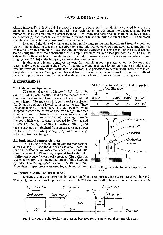
2. EXPERIMENTS Table 1 Density and mechanical properties
2.1 Material and Specimen of Mullite tube. The material tested is Mullite ( Al,O, : 53 wt.%,
SiO, : 41 wt.% ) ceramic tube, sold on the market, with 6 E Or Ob P mm in outer diameter, 1 mm in wall thickness and 300 (GPa) (MPa) (MPa) (kg/m3) mm in length. The tube was just cut to make specimens for dynamic and static lateral compression tests. Three 114 0.25 90 157 2 . 6 ~ 1 0 ~ different lengths of svecimen. 4, 7 and 10 mm. were adopted to ciieck the iffect of specimen length. In order to obtain basic mechanical properties of tube material, static tensile tests were perforked by using a simple method which was recently proposed by Nojima and Iiyama[l7]. Young's modulus, E, Poisson's ratio, v, and tensile strength, o,, obtained from tensile tests are shown in Table 1 with bending strength, o, , and density, p, which are from a catalogue.
2.2 Static lateral compression test The setting for static lateral compression tests is
shown in Fig. 1. Since the dimension is small, both the load and deflection are very small such, 300 N and 0.05 mm, respectively. Therefore, a special load cell and a
Strain gauges 4 Load cell
Specimen
Deflection
l r - ' I cylinder 1 1 1 1 1 I' I 1 Strain gauges
"deflection cylinder" were newly prepared. The deflection was obtained from the longitudinal strain of the deflection cylinder. The testing speed is about 2 x 10.' mrnlmin. More than 10 specimens were used for each kind of test. Fig,l Setting for static lateral compression
tests. 2.3 Dynamic lateral compression test
Dynamic tests were performed by using split Hopkinson pressure bar system, as shown in Fig.2. The input, output and striking bars are made of A6063 aluminium alloy tube with outer diameters of 16
V, = 1.2 m/sec Strain gauge Strain gauge A Specimen
Striking bar Input bar Output bar - - -- -- 1 250 I [ ' ' ~ ] ~ ~ ~ ~ i t : mm
Fig.2 Layout of split Hopkinson pressure bar used for dynamic lateral compression test.
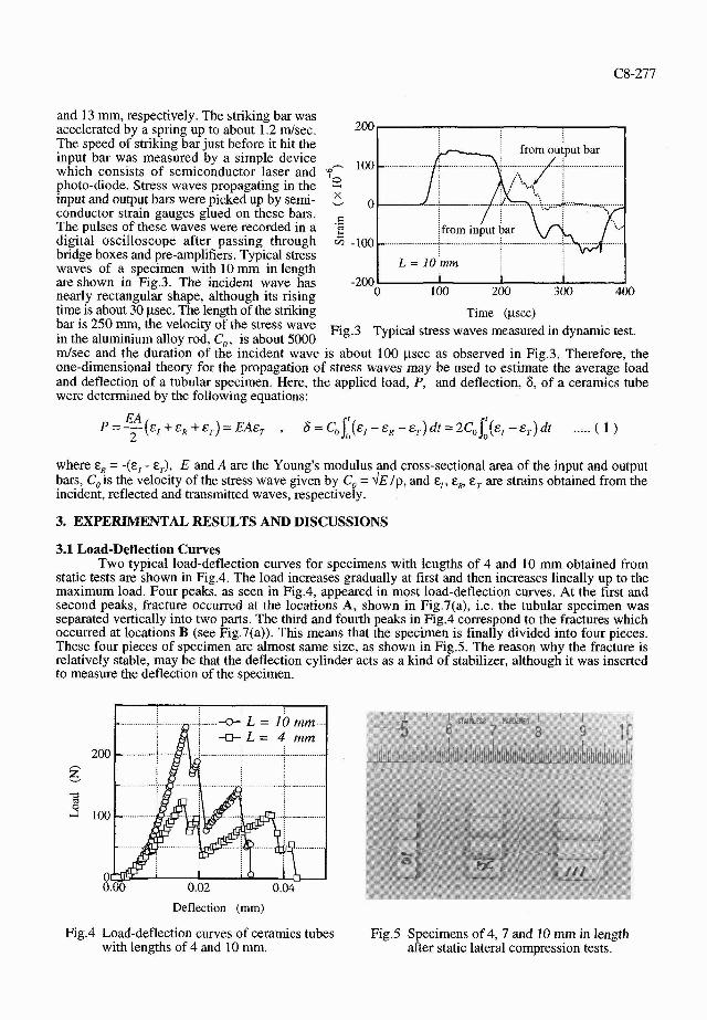
and 13 mm, respectively. The striking bar was accelerated by a spring up to about 1.2 mlsec. 2 0 0 / The speed of striking bar just before it hit the input bar was measured by a simple device 100 - ............... which consists of semiconductor laser and yn photo-diode. Stress waves propagating in the 2 input and output bars were picked up by semi- 0 conductor strain gauges glued on these bars. = The pulses of these waves were recorded in a .z
............... digital oscilloscope after passing through 6 -100 - bridge boxes and pre-amplifiers. Typical stress
L = 10mm waves of a specimen with 10 mm in length are shown in Fig.3. The incident wave has -200 I I I
nearly rectangular shape, although its rising 0 100 200 300 400 time is about 30 psec. The length of the striking Time (psec) bar is 250 -, the of the wave Fig.3 Typical stress waves measured in dynamic test. in the aluminium allov rod. C,. is about 5000 rnlsec and the duratibn of tce incident wave is about 100 ysec as observed in Fig.3. Therefore, the one-dimensional theory for the propagation of stress waves may be used to estimate the average load and deflection of a tubular specimen. Here, the applied load, P, and deflection, 6, of a ceramics tube were determined by the following equations:
where E, = -(E, - E,), E and A are the Young's modulus and cross-sectional area of the input and output bars, Co is the velocity of the stress wave given by Co = .\IE lp, and E,, E,, E, are strains obtained from the incident, reflected and transmitted waves, respectively.
3. EXPERIMENTAL RESULTS AND DISCUSSIONS
3.1 Load-Deflection Curves Two typical load-deflection curves for specimens with lengths of 4 and 10 mm obtained from
static tests are shown in Fig.4. The load increases gradually at first and then increases lineally up to the maximum load. Four peaks, as seen in Fig.4, appeared in most load-deflection curves. At the first and second peaks, fracture occurred at the locations A, shown in Fig.7(a), i.e. the tubular specimen was separated vertically into two parts. The third and fourth peaks in Fig.4 correspond to the fractures which occurred at locations B (see Fig.'l(a)). This means that the specimen is finally divided into four pieces. These four pieces of specimen are almost same size, as shown in Fig.5. The reason why the fracture is relatively stable, may be that the deflection cylinder acts as a kind of stabilizer, although it was inserted to measure the deflection of the specimen.
Deflection (mm)
Fig.4 Load-deflection curves of ceramics tubes Fig.5 Specimens of 4, 7 and 10 mm in length with lengths of 4 and 10 mm. after static lateral compression tests.

C8-278 JOURNAL DE PHYSIQUE IV
Fig.6 shows the result of dynamic tests with a 10 mm specimen. The load increases almost linearly up to the maximum load, as in the static results. Since the slope of this region is almost the same as in static tests, Young's 4
a 1.2 3
modulus may not be affected by loading rate. However, the maximum load in dynamic tests
3 s cr. is much greater than that obtained from static o tests, see Fig.4. This may be caused by the 3
effect of loading rate. After the first peak, two or three more peaks are observed. These g 2 0.6 3 g peaks may correspond to the vertical and r\
horizontal fractures in the static tests. The deformation speed is also shown in Fig.6 and 3
8 is equal to dWdt = 2C0 (E, - q), see equ.(l). - Although a drop is observed close to the deflection of 6 = 0.014 mm, the speed until 0.0
0.00 0.02 0.04 the first peak of the load is roughly 0.6 d s e c . If the striking bar has the same cross-sectional Deflection (mm) area as the input bar, the particle velocity in Fig.6 Load-deflection curve and deformation speed the input bar becomes half that of the striking observed in a dynamic test. bar. Therefore, this is quite reasonable because the speed of the striking bar is about 1.2 d s e c , as mentioned before.
3.2 Estimation of Young's modulus and fracture stress When we think about the deformation
of a circular tube in lateral compression as shown in Fig.7(a), the deformation of a quadrant is usually considered from equilibrium and symmetry of the deformation. Fig.7(b) shows the system of forces and B- moments acting on one quadrant during deformation. If the tube is thin-walled tube, i.e. the mean radius, R, is much greater than the wall thickness, h, the effect of the longitudinal force, N, and shear force, V, can be negligible compared with that of the bending moment, M. However, the R and h of the specimen used in this study, are 2.5 and 1 Fig.7 System of forces and moments on a quadrant. mm, respectively. Therefore, we have to take M, Nand V into account. The strain energy absorbed in a quadrant, UQ, can be written by
~ 1 2 ~ ' N' MN u* =jo ( -+--- v' + a-)Rd@ 2EI 2LhE LhER 2LhG
where E and G (=E/ (2(l+v))) are the Young's modulus and the shear modulus of the ceramic tube and I is a value corresponding to the second moment of area for a straight beam, given by ~h'/12. a is a numerical factor by which the average shear stress must be multiplied to obtain the shear stress at the centroid of the cross section, e.g. a = 312 for a rectangular cross section and a = 413 for a circular cross section. Here, we adopted a'= 1.2 as used in the reference[l8]. From Fig.7(b), M, N, and V are given by
where M, is obtained by using equ.(2) and a boundary condition, which is (due / dMo ) = 0 at the vertical cross section A-A' in Fig.7(b). The total strain energy of a circular tube, U, is equal to 4UQ and the deflection, 6, can be given by 6 = (dU/ dP). Therefore, 6 may be expressed by
C8-279
From equ.(4), we can obtain the expression for Young's modulus as follows:
l^r.L.U_H*+2a(\ + v)H*~-(l-H*f\ , H* h2
12R2 .(5)
The bending stress on the inner surface of a curved beam is given by the following equation [19],
„ _ M0(h/2-e) Lhe(R-hll)
(6)
where e is the distance from the centroid axis to the neutral axis of the cross section, approximately given by e=RH* for a rectangular cross section. As mentioned before, fracture occurs at location A when the load reaches the maximum load, Pmux. Therefore, if we consider M0 = (PmaxR /it)( 1 - H*) from equ.(3) and put it into equ.(6), the fracture stress, Cy*, can be determined by
af*-C (l-H*)(h/2-RH*) nLh H*(R-h/2)
(7)
By using equ.(5) and equ.(7), Young's modulus and fracture stress can be obtained from the results of lateral compression tests.
The analysis shown above is based on elementary static curved beam theory. In general, it seems to be difficult to apply the beam theory to the beam with relatively large curvature and thickness such as the mean radius , R = 2.5 mm and the thickness, h = 1 mm. In the analysis, however, the slope of load-deflection curves up to the first peak and the bending stress at location A (see Fig.7(b)) are used to evaluate the Young's modulus and fracture stress of ceramic tubes, respectively. We have already verified that both the slope of P-8 curves and the bending stress at A obtained from equs.(4) and (7) agreed well with the results of FEM analysis[20]. Therefore, we think that there is no problem to use equs.(4) and (7). As mentioned in the section 3.1, £ is not affected by loading rate. In the range of this paper, therefore, the equs.(4) and (7) may be used to the results of dynamic tests, as the first approximation.
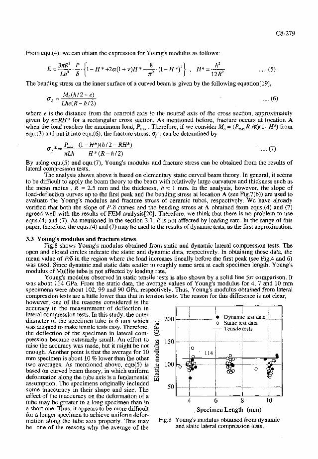
3.3 Young's modulus and fracture stress Fig.8 shows Young's modulus obtained from static and dynamic lateral compression tests. The
open and closed circles indicate the static and dynamic data, respectively. In obtaining these data, the mean value of P/S in the region where the load increases lineally before the first peak (see Fig.4 and 6) was used. Since dynamic and static data scatter in roughly same area at each specimen length, Young's modulus of Mullite tube is not affected by loading rate.
Young's modulus observed in static tensile tests is also shown by a solid line for comparison. It was about 114 GPa. From the static data, the average values of Young's modulus for 4, 7 and 10 mm specimena were about 102, 99 and 90 GPa, respectively. Thus, Young's modulus obtained from lateral compression tests are a little lower than that in tension tests. The reason for this difference is not clear, however, one of the reasons considered is the accuracy in the measurement of deflection in lateral compression tests. In this study, the outer diameter of the specimen tube is 6 mm which was adopted to make tensile tests easy. Therefore, the deflection of the specimen in lateral compression became extremely small. An effort to raise the accuracy was made, but it might be not enough. Another point is that the average for 10 mm specimen is about 10 % lower than the other two averages. As mentioned above, equ(5) is based on curved beam theory, in which uniform deformation along the tube axis is a fundamental assumption. The specimens originally included some inaccuracy in their shape and size. The effect of the inaccuracy on the deformation of a tube may be greater in a long specimen than in a short one. Thus, it appears to be more difficult for a longer specimen to achieve uniform deformation along the tube axis properly. This may be one of the reasons why the average of the
2 0 0 -CL,
a
3 -a o S _o on cs W
150
100
50
• Dynamic test data.. o Static test data
— Tensile tests
Specimen Length (mm)
Fig.8 Young's modulus obtained from dynamic and static lateral compression tests.

JOURNAL DE PHYSIQUE .IV
4. CONCLUSIONS
shortest specimen is highest. From these
In order to investigate the deformation of Mullite ceramics tube in lateral compression, a series of experiments was carried out at dynamic and static rates. Static tensile tests were also performed to determine the basic mechanical properties of Mullite ceramics tube. Principal results obtained are: 1. Expressions for Young's modulus and fracture stress can be derived theoretically by considering the
deformation of thick tube in lateral compression. By using the expressions, Young's modulus and fracture stress of ceramics tube are obtained from the results of lateral compression tests.
2. The effects of loading rate on Young's modulus were not found. In estimation of Young's modulus from lateral compression tests, the specimen with W2R I 1 is recommended, although it may be slightly underestimated comparing with tension tests.
3. The average fracture stress obtained from dynamic lateral compression tests was about 1.6 times greater than that obtained from static tests. Therefore, the strength of Mullite tube is affected by loading rate. It was also found in static data that the fracture stress agreed well with the bending strength of the Mullite tube.
discussion, the specimen with W2R I 1 is recommended to estimate Young's modulus of ceramic tube from lateral compression tests. - 400
Fracture stresses of tubular specimens in 2 static and dynamic lateral compression were 8 calculated by equ.(7) and shown in Fig.9. In the
v, 300 figure, open circles, closed circles, a dotted line and a broken line are, respectively, static data, dynamic data and average lines of dynamic and 2 static data. The solid line indicates the catalogue 3 200 value of the bending strength of Mullite tube. 2 As shown in static data, the average fracture & stresses of specimen with lengths of 4 and 10 mm are about 157 MPa and 133 M P r respec- 100
REFERENCES
0 ~ ~ n a m , c test data :
............................... ------..-.-. - static test data ......... Average (Dynamic) - - . Average (Static) - Bending strength
......................... ......................... ...........- -........;..........-.........A i ; ! @ / 0 ; .j.
-4 .......................... 8. i i. i* : W . ' F . . . . &..
........ ......................... ................>...... - j ..r................. i ~......... e... { o 1 5 7 : @ /
o - - - _ ! _ _ ; %----- 0 - - 6
...... - ...................... , . . . . . . 8 ........ ........................ @
[ 1 ] Mutchler L.D., J. Appl. Mech. Trans. ASME srr.E, 27 (1960) 740-743. [ 2 I Deruntz Jr. J.A. and Hodge Jr. P.G., J. Appl. Mrch. Trans. ASME ser.E, 30 (1963) 391-395. [ 3 ] Redwood R.G., J. Appl. Mech. Trans. ASME ser.E, 31 (1964) 357-358. [ 4 I Reid S.R. and Reddy T.Y., Int. J. Solids Struct., 14 (1978) 213-225. [ 5 ] Goto M. and Shibata Y., Trans. JSME ser. A, 56 (1990) 2002-2010. [ 6 1 Kobayashi H and Daimaruya M., Trans. JSME ser. A, 57 (1991) 1371-1377. 17 1 Kobavashi H. Daimaruva M. and Nagai K.. Trans. JSME ser. A. 57 (1991) 1378-1383.
tively, i.e. the average fracture stress of 10 rnm specimen is about 15 % lower than that of 4 4 6 8 10 rnm specimen. The number of defects involved Specimen Length (mm) in a longer specimen is greater than that in a shorter specimen. Therefore, the probability of Fig.9 Fracture stress ob~cmed in dynamic and involving larger defects in longer specimens static lateral compression tests. becomes higher. This may be one of the reasons of the difference between average fracture stresses of 4 and 10 mm specimens. Similar tendency is also seen in dynamic data. In each specimen length, however, the average fracture stress at dynamic rate is about 1.6 times greater than that observed in static tests. This may result from the effect of loading rate.
8 i ~irai?. , Yokoyama and Murata T., J. ~ o c . Mater. Sci. ~ a ~ a n ; 35 (1986) 354-360. [ 9 ] Reid S.R. and Reddy T.Y., "'Effect of strain rate on the dynamic lateral compression of tubes" Int. Conf. Mech. Prop. of Materials at
High Rates of Strain, Oxford, (Harding J. ed. 1979) pp. 288-298. [lo] Kobayashi H. Daimaruya M. and Nagai K., "Dynamic and static behaviour of circular tubes in lateral compression", 7th Int. Cong.
Exper. Mech., Las Vegas 8-11 June 1992 pp. 1654-1659. [ I I] Hirai T., imaida Y., Katayama T and Kobayashi N., J. Soc. Marer. Sci. Japan, 39 (1990) 254-260. [I21 Calladine C.R. and English R.W., Int. J. Mech. Sci., 26 (1984) 689-701. [13] Zhang T.G. and Yu T.X., Int. J. Impact Engng., 8 (1989) 43-5 1. [14] Veillette J.R. and Carney I11 J.F., Int. J. Intpacr Engng., 7 (1988) 125.138. [15] Reid S.R., Bell W.W. and Barr R.A., Int. J. Impact Engng., I(1983) 175-191. 1161 Reddv T.Y.. Kaddour A.S. and Reid S.R.. "Dvnamic indentation of two-dimentional ring svstems". Int. Conf. Mech. Prov. of . . - .
~ a t e k a l s at High Rates of Strain, Oxford, (Hard& J. ed. 1984) pp. 447- 455. [I71 NojimaT. and IiyamaT., J. Soc Muter. Sci Japan, 42 (1993) 209-213. [IS] Timoshenko S., Strength of materials Pan I (D. Van Nostrand Company Ltd, 1955) pp. 378-385. 1191 Timoshenko S. and Young D.H., Elements of strength of materials, fourth edition (D. Van Nostrand Company, 1962) pp. 167-172. [20j Personal contacts with regree of this paper.
Related Documents