Dynamic analysis of the Empact CVT : ratio and slip dependent, non-minimum phase dynamics Citation for published version (APA): Klaassen, T. W. G. L., Bonsen, B., Meerakker, van de, K. G. O., Vroemen, B. G., Veenhuizen, P. A., & Steinbuch, M. (2005). Dynamic analysis of the Empact CVT : ratio and slip dependent, non-minimum phase dynamics. In Dynamik und Regelung von Automatischen Getrieben (pp. CDROM-). Document status and date: Published: 01/01/2005 Document Version: Accepted manuscript including changes made at the peer-review stage Please check the document version of this publication: • A submitted manuscript is the version of the article upon submission and before peer-review. There can be important differences between the submitted version and the official published version of record. People interested in the research are advised to contact the author for the final version of the publication, or visit the DOI to the publisher's website. • The final author version and the galley proof are versions of the publication after peer review. • The final published version features the final layout of the paper including the volume, issue and page numbers. Link to publication General rights Copyright and moral rights for the publications made accessible in the public portal are retained by the authors and/or other copyright owners and it is a condition of accessing publications that users recognise and abide by the legal requirements associated with these rights. • Users may download and print one copy of any publication from the public portal for the purpose of private study or research. • You may not further distribute the material or use it for any profit-making activity or commercial gain • You may freely distribute the URL identifying the publication in the public portal. If the publication is distributed under the terms of Article 25fa of the Dutch Copyright Act, indicated by the “Taverne” license above, please follow below link for the End User Agreement: www.tue.nl/taverne Take down policy If you believe that this document breaches copyright please contact us at: [email protected] providing details and we will investigate your claim. Download date: 27. Jan. 2022

Welcome message from author
This document is posted to help you gain knowledge. Please leave a comment to let me know what you think about it! Share it to your friends and learn new things together.
Transcript
Dynamic analysis of the Empact CVT : ratio and slipdependent, non-minimum phase dynamicsCitation for published version (APA):Klaassen, T. W. G. L., Bonsen, B., Meerakker, van de, K. G. O., Vroemen, B. G., Veenhuizen, P. A., &Steinbuch, M. (2005). Dynamic analysis of the Empact CVT : ratio and slip dependent, non-minimum phasedynamics. In Dynamik und Regelung von Automatischen Getrieben (pp. CDROM-).
Document status and date:Published: 01/01/2005
Document Version:Accepted manuscript including changes made at the peer-review stage
Please check the document version of this publication:
• A submitted manuscript is the version of the article upon submission and before peer-review. There can beimportant differences between the submitted version and the official published version of record. Peopleinterested in the research are advised to contact the author for the final version of the publication, or visit theDOI to the publisher's website.• The final author version and the galley proof are versions of the publication after peer review.• The final published version features the final layout of the paper including the volume, issue and pagenumbers.Link to publication
General rightsCopyright and moral rights for the publications made accessible in the public portal are retained by the authors and/or other copyright ownersand it is a condition of accessing publications that users recognise and abide by the legal requirements associated with these rights.
• Users may download and print one copy of any publication from the public portal for the purpose of private study or research. • You may not further distribute the material or use it for any profit-making activity or commercial gain • You may freely distribute the URL identifying the publication in the public portal.
If the publication is distributed under the terms of Article 25fa of the Dutch Copyright Act, indicated by the “Taverne” license above, pleasefollow below link for the End User Agreement:www.tue.nl/taverne
Take down policyIf you believe that this document breaches copyright please contact us at:[email protected] details and we will investigate your claim.
Download date: 27. Jan. 2022

Dynamic analysis of the Empact CVTRatio and slip dependent, non-minimum phase dynamics
T.W.G.L. Klaassen, B.G. Vroemen and M. SteinbuchEindhoven University of Technology, Department of Mechanical EngineeringP.O. Box 513, 5600MB Eindhoven, The Netherlands
Abstract
The dynamics of an electromechanically actuated metal V-belt (Empact) CVT is analyzed by
studying a simplified linear model of the actuation system and a driveline model which includes
the slip dynamics of the variator. The actuation system shows several CVT ratio depending
modes. Linearization of the slip dynamics shows that the location and, moreover, the damping
of the modes depends significantly on the amount of slip in the variator. Using pole-zero loca-
tions of the system it is shown that due to high overclamping a coupling between the primary
and secondary side of the variator occurs with very large damping and due to underclamping
the input and output sides of the variator are decoupled with low or even negative damping,
resulting in an unstable system. Furthermore non-minimum phase behavior of the actuation is
described. Using identification results from a non-linear model of the Empact CVT the interac-
tion of the actuation and driveline dynamics is analyzed. Finally, measurements on a prototype
of the Empact show similar behavior, however with very large damping of all of the modes.
1 Introduction
The pulleys of a pushbelt or chain type CVT are actuated axially to adjust transmission ratio
and to apply slip-preventing belt clamping force. In conventional CVTs this is done using hy-
draulics. Hydraulic losses are however substantial. To reduce the energy consumption, an
electromechanically actuated CVT is developed [6], also referred to as the Empact CVT. By
using a double epicyclic gear system and a screw mechanism at both shafts of the CVT (fig-
ure 1), it is possible to actuate the metal V-belt CVT with two servomotors at the fixed world.
That means that the rotation of the servomotors is decoupled from the rotation of the input and
output shaft of the CVT. By rotating the primary servomotor, a relative rotation between the two
sun gears of the epicyclic sets is realized. This results in a translation of the spindles at both
pulleys. At the secondary side, by adjusting the torque delivered by the secondary servomotor,
1

P r i m a r yp u l l e y
S e c o n d a r yp u l l e y
s p i n d l e
s p i n d l e
M p
M s
T C , e n g i n e
w h e e l s
t h r u s t b e a r i n g
c h a i n g e a r
w o r m g e a r
Figure 1: Electro-mechanically actuated CVT
the clamping force in the variator can be set and controlled. This system has the advantage
that only mechanical power is needed when the CVT is shifting or when the clamping force is
changed. The energy losses are reduced to a minimum in this way.
For analysis, control design and testing of the Empact CVT, a simulation model is built. This
model is described in [4]. Due to its complexity and nonlinear behavior, this model is not
suitable for control design. To use modern control design techniques like µ-synthesis, linear
transfer functions from all inputs to all outputs must be known. Klaassen et al. [3] presents
the identification of a linearized model from the non-linear simulation model using approximate
realization techniques.
This paper first gives a dynamical analysis of the Empact CVT by studying the modes of the ac-
tuation system and the driveline separately. Furthermore non-minimum phase behavior of the
system will be described. The interaction of these dynamics are described using identification
results from a non-linear model of the Empact CVT in section 3. Finally to validate the analytic
model, results from identification measurements will be shown.
2 Dynamic analysis
The model described in [4] includes all major driveline components and the electromechani-
cally actuated CVT. A detailed model of the variator is implemented, which gives an accurate
estimation of the clamping forces and slip in the system. In this model the worm gear with its
2

100 101 102-1000-800-600-400-200
0200
100 101 102-80-60-40-20
02040
100 101 102-2000-1500-1000-500
0500
100 101 102-100-80-60-40-20
020
100 101 102-1500
-1000
-500
0
100 101 102-150
-100
-50
0
50
100 101 102-400
-300
-200
-100
0
100 101 102-80-60-40-20
02040
Frequency [Hz]
Input 2
Pha
se[◦
]
Frequency [Hz]
Mag
nitu
de[d
B]
Pha
se[◦
]
Input 1
Mag
nitu
de[d
B]
Figure 2: Transfer function from Tmp (Input 1) and Tms (Input 2) to rg (Output 1) and ν (Output
2) at rg = 0.5 (-), rg = 1 (- -) and rg = 2 (-.)
bearing support, the chain at the secondary actuation and the thrust bearings, which support
the axial force between the sun gears of the epicyclic gears at the primary and secondary side,
are modeled as spring elements. As described in [3] and [1], the controlled variables are the
geometric ratio rg and the slip ν in the variator. The control inputs are the primary and sec-
ondary servo torque, Tmp and Tms respectively. Linearization of the nonlinear model from these
inputs to the outputs using approximate realization from step responses result in slip and ratio
dependent transfer functions [3]. Figure 2 shows the transfer functions at ratio low, medium
and overdrive. To get more insight in the resonances visible in the transfers function, the sys-
tem is divided into two parts, i.e. a linear model for the actuation system and a model for the
driveline, in this case the testbench. Furthermore non-minimum phase behavior resulting from
the geometry of the variator will be described.
3

2.1 Actuation system
The first part is a linear, lumped parameter representation of the actuation system as shown in
figure 3. In this model the pushbelt is represented as a flexible element. The stiffness of this el-
ement is the longitudinal stiffness of the steel bands of the pushbelt, combined with the stiffness
of the pushing segments on the tense side. The thrust bearings are modeled as translational
springs which support the screw output in longitudinal direction. The worm is represented as
a rotational spring between the output of the worm and the ring gear of the epicyclic gear at
the primary side. Finally the chain which connects the secondary servo to the ring gear of
the epicyclic set is modeled as a flexible element. All flexible elements are subjected to pro-
portional damping. Other non-conservative forces that act on the system are viscous friction
in both servos and screws and a damping force that acts on the pulleys according to Shafai’s
model [5].
The epicyclic sets are modeled as a normal gear with a ratio of 2, which is the ring to sun ratio.
The carriers and planets of the epicyclic sets are not modeled as separate bodies, but their in-
ertias are combined with the ring inertia. The screws make the connection from the translating
to the rotating part by their kinematic relation xin − xout = s (θin − θout) where xin and xout are
the input (nut) and output (bolt) translations, θin and θout are the input and output rotations and
s is the pitch. For clarity, the part of the screw that is connected to the corresponding pulley
is called the output side. The inertias of the screws are combined with the inertias of the sun
gears, whereas the mass of the output of the screw is combined with the mass of the pulley.
Using Lagrange’s equations of motion a dynamic model can be derived for this system. Six
generalized coordinates are required to describe the system, that is the rotation of the primary
servo q1, the rotation of the secondary servo q2, the rotation of the primary sun gear at the out-
put side of the screw q3, the rotation of the secondary sun gear at the input side of the screw q4,
the translation of the primary pulley q5 and the translation of the secondary pulley q6. Note that
by the coupling of the ring gear between the primary and secondary side, the rotation of the
sun at the output side of the secondary screw can also be expressed as q3. Furthermore, the
translation of the input of the primary and secondary screw can be expressed as q7 = sq3 + q5
and q8 = s (q4 − q3) + q6 respectively.
4

Primary sideSecondary side
Translation
Rotation
pushbelt
thrust
bearing
thrust
bearing
screw screw
pulley pulley
chain
1:5
reduction
1:4
1:2 1:2 1:2
epicyclic set
1:20
worm
worm
stiffness
Secondary
servo
Primary
servo
q
1
q
2
q
3
q
4
q
5
q
6
q
7
q
8
Figure 3: Linear representation of the actuation system
Undamped eigenmodes
By forming the mass matrix M and stiffness matrix K, the undamped eigenfrequencies fr and
corresponding eigenvectors can be calculated. The eigenfrequencies are listed in table 1. The
eigenvectors are mass-normalized and normalized for the gear and screw ratios so that they
all have the same order of magnitude. Figure 4 shows the eigenvectors for rg = 1. Here also
the normalized displacements of q7 and q8 are shown. For the sake of clarity, the high frequent
modes are plotted in the right figure. Furthermore, figure 5 shows the normalized potential
energy of the five spring elements in each mode. Here spring numbers 1 to 5 are the worm,
chain, pushbelt, primary and secondary thrust bearing respectively. The sign of the energy
shows whether the spring is elongated or shortened. From these two figures it is possible to
see the influence of the bodies and springs on each mode. For matter of convenience, the
normalized eigenvectors are referred to as displacements q1−8.
As expected a rigid body mode is present, where q1 to q6 are equal and q7 = q8 = 0. The
potential energy is of course zero here. The second eigenvector with fr = 10.7 [Hz] originates
from the worm stiffness in combination with belt and thrust bearings. In this case the rotation
of q1 and q3 is in the same direction. The third mode at fr = 17.3 shows similar behavior, but in
this case q1 and q3 are opposite in direction. For the mode at fr = 47.9 [Hz] it is clear that this
originates from the chain at the secondary servo. The potential energy of the other elements
are close to zero in this mode. The two translational modes are both at very high frequency.
Mode number 5 is an in-phase translation of both pulleys, whereas mode 6 is an out of phase
5
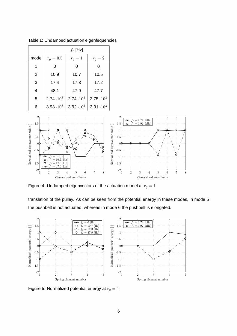
Table 1: Undamped actuation eigenfequencies
fr [Hz]
mode rg = 0.5 rg = 1 rg = 2
1 0 0 0
2 10.9 10.7 10.5
3 17.4 17.3 17.2
4 48.1 47.9 47.7
5 2.74 ·103 2.74 ·103 2.75 ·103
6 3.93 ·103 3.92 ·103 3.91 ·103
1 2 3 4 5 6 7 8-2
-1.5
-1
-0.5
0
0.5
1
1.5
2
1 2 3 4 5 6 7 8-2
-1.5
-1
-0.5
0
0.5
1
1.5
2fr = 2.74 [kHz]fr = 3.92 [kHz]
fr = 0 [Hz]fr = 10.7 [Hz]fr = 17.3 [Hz]fr = 47.9 [Hz]
Nor
mal
ized
eige
nvec
tor
valu
e[-]
Generalized coordinate
Nor
mal
ized
eige
nvec
tor
valu
e[-]
Generalized coordinate
Figure 4: Undamped eigenvectors of the actuation model at rg = 1
translation of the pulley. As can be seen from the potential energy in these modes, in mode 5
the pushbelt is not actuated, whereas in mode 6 the pushbelt is elongated.
1 2 3 4 5-2
-1.5
-1
-0.5
0
0.5
1
1.5
2
1 2 3 4 5-2
-1.5
-1
-0.5
0
0.5
1
1.5
2fr = 2.74 [kHz]fr = 3.92 [kHz]
Nor
mal
ized
pote
ntia
len
ergy
[-]
Spring element number
fr = 0 [Hz]fr = 10.7 [Hz]fr = 17.3 [Hz]fr = 47.9 [Hz]
Nor
mal
ized
pote
ntia
len
ergy
[-]
Spring element number
Figure 5: Normalized potential energy at rg = 1
6
10�2 10�1 100 101 102 103-200
-150
-100
-50
0
10�2 10�1 100 101 102 103-200
-150
-100
-50
0
50
10�2 10�1 100 101 102 103-200
-150
-100
-50
0
10�2 10�1 100 101 102 103-200
-150
-100
-50
0
50
Frequency [Hz]
Tms → θms
Pha
se[◦
]
Frequency [Hz]
Tmp → θmp
Mag
nitu
de[d
B]
Figure 6: Transfer functions from servo torque to position, undamped (–), moderate damping
(-.), and large damping (- -)
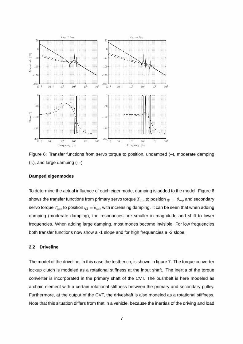
Damped eigenmodes
To determine the actual influence of each eigenmode, damping is added to the model. Figure 6
shows the transfer functions from primary servo torque Tmp to position q1 = θmp and secondary
servo torque Tms to position q2 = θms with increasing damping. It can be seen that when adding
damping (moderate damping), the resonances are smaller in magnitude and shift to lower
frequencies. When adding large damping, most modes become invisible. For low frequencies
both transfer functions now show a -1 slope and for high frequencies a -2 slope.
2.2 Driveline
The model of the driveline, in this case the testbench, is shown in figure 7. The torque converter
lockup clutch is modeled as a rotational stiffness at the input shaft. The inertia of the torque
converter is incorporated in the primary shaft of the CVT. The pushbelt is here modeled as
a chain element with a certain rotational stiffness between the primary and secondary pulley.
Furthermore, at the output of the CVT, the driveshaft is also modeled as a rotational stiffness.
Note that this situation differs from that in a vehicle, because the inertias of the driving and load
7

TC
stiffness
q
1
q
2
q
3
q
4
Load
motor
Driving
motor
CVT
Driveshaft
stiffness
Figure 7: Schematic representation of the driveline
Table 2: Undamped driveline eigenfrequencies
fr [Hz]
mode rg = 0.5 rg = 1 rg = 2
1 0 0 0
2 3.52 4.14 5.38
3 24.0 22.5 19.7
4 236 205 184
motor are different from the inertias in a vehicle.
The generalized coordinates are the angular rotation of the four bodies. Table 2 and figure 8
show the eigenfrequencies, normalized eigenvectors and normalized potential energy of the
system. The first eigenmode is again a rigid body mode. The second mode at fr = 4.14 [Hz] is
mainly due to the driveshaft stiffness as can be seen from the potential energy plot. The third
eigenmode at fr = 22.5 [Hz] can be allocated to the torque converter stiffness. The last mode
at relatively high frequency is due to the pushbelt stiffness.
1 2 3-2
-1.5
-1
-0.5
0
0.5
1
1.5
2
1 2 3 4-2
-1.5
-1
-0.5
0
0.5
1
1.5
2fr = 0 [Hz]fr = 4.14 [Hz]fr = 22.4 [Hz]fr = 205 [Hz]
Nor
mal
ized
pote
ntia
len
ergy
[-]
Spring element number
Nor
mal
ized
eige
nvec
tor
valu
e[-]
Generalized coordinate
Figure 8: Undamped eigenvectors and potential energy at rg = 1
8

Slip dynamics
If the pushbelt is modeled as a spring element like in the aforementioned model, by definition
no slip would be present. However, if in the limiting case the pushbelt stiffness is zero, slip can
be present. In practise, the coupling between the primary and secondary pulley is realized by
the transmitted belt torque [2] given by
Tb =2µ(ν, rg)FsRs
cos(β)(1)
where µ(ν, rg) is a slip and ratio dependent traction coefficient, Fs is the clamping force at the
secondary pulley, Rs is the running radius of the belt on the secondary pulley and β is the pulley
wedge angle. Slip in the variator is defined as
ν = 1− ωsRs
ωpRp(2)
where ωp = q2 and ωs = q3 corresponding to the driveline model and Rp is the running radius
of the belt on the primary pulley. The ratio rg = Rp/Rs is referred to as the geometric ratio.
If this belt torque is linearized with respect to the state vector x = [q1 . . . q4 q1 . . . q4]T and the
input u = Fs, around a certain operating point x = x0+x and u = u0+u at a constant geometric
ratio rg, this results in
Tb =2µ′(ν0, rg)u0Rp
q20 cos(β)rg
(q30
q20
˜q2 − ˜q3
)+
2µ(ν0, rg)Rs
cos(β)u (3)
where µ′(ν0, rg) is the slope of the traction curve at the corresponding slip value. Hence, the
belt torque can be modeled as a linear damper with damping constant cb = 2µ′(ν0,rg)Fs0Rp
q20 cos(β)rg
[Ns/rad] between the primary and secondary pulley, i.e. between the generalized coordinates
q2 and q3.
In case the damping constant of this damper is small, the primary and secondary side of the
driveline are decoupled. In this situation two rigid body modes are present, one mode of the
primary side at fr = 15.5 [Hz] and one mode of the secondary side at fr = 24.6 [Hz]. However,
with increasing damping cb coupling between the primary and secondary side occurs. Figure 9
shows the root locus of the system for increasing cb. It can be seen that the damping of the
complex pole pair at 15.5 [Hz] increases as it turns towards the real axis. At the real axis, one
of these poles goes to −∞, whereas the other goes towards 0. Due to increasing coupling be-
tween both shafts, one of the rigid body mode poles goes from 0 towards negative real values.
At a certain point the two real poles become one complex conjugate pair. A further increase of
9
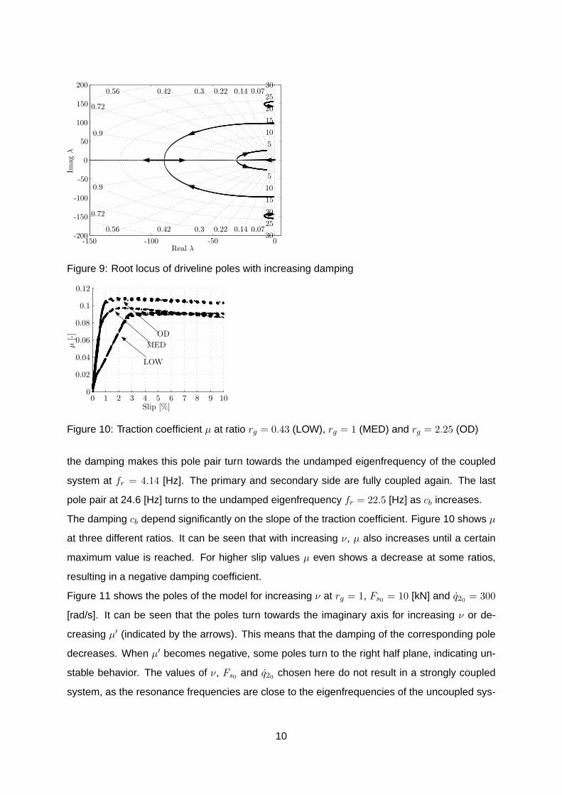
-150 -100 -50 0-200
-150
-100
-50
0
50
100
150
200
Imag
λ
Real λ
0.070.140.220.30.420.56
0.72
0.9
0.070.140.220.30.420.56
0.72
0.9
5
10
15
20
2530
5
10
15
20
2530
Figure 9: Root locus of driveline poles with increasing damping
0 1 2 3 4 5 6 7 8 9 100
0.02
0.04
0.06
0.08
0.1
0.12
ODMED
LOW
µ[-]
Slip [%]
Figure 10: Traction coefficient µ at ratio rg = 0.43 (LOW), rg = 1 (MED) and rg = 2.25 (OD)
the damping makes this pole pair turn towards the undamped eigenfrequency of the coupled
system at fr = 4.14 [Hz]. The primary and secondary side are fully coupled again. The last
pole pair at 24.6 [Hz] turns to the undamped eigenfrequency fr = 22.5 [Hz] as cb increases.
The damping cb depend significantly on the slope of the traction coefficient. Figure 10 shows µ
at three different ratios. It can be seen that with increasing ν, µ also increases until a certain
maximum value is reached. For higher slip values µ even shows a decrease at some ratios,
resulting in a negative damping coefficient.
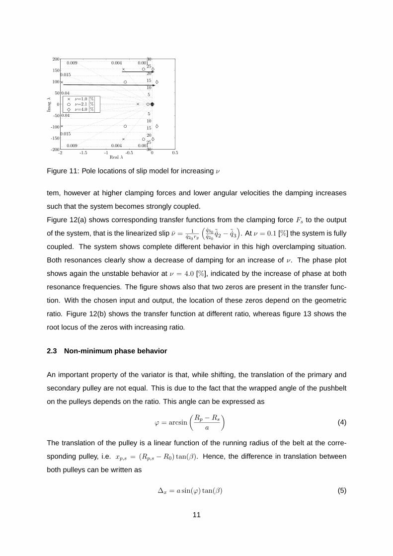
Figure 11 shows the poles of the model for increasing ν at rg = 1, Fs0 = 10 [kN] and q20 = 300
[rad/s]. It can be seen that the poles turn towards the imaginary axis for increasing ν or de-
creasing µ′ (indicated by the arrows). This means that the damping of the corresponding pole
decreases. When µ′ becomes negative, some poles turn to the right half plane, indicating un-
stable behavior. The values of ν, Fs0 and q20 chosen here do not result in a strongly coupled
system, as the resonance frequencies are close to the eigenfrequencies of the uncoupled sys-
10
-2 -1.5 -1 -0.5 0 0.5-200
-150
-100
-50
0
50
100
150
200
ν=1.0 [%]ν=2.1 [%]ν=4.0 [%]Im
agλ
Real λ
0.0010.0040.009
0.015
0.04
0.0010.0040.009
0.015
0.04
5
10
15
20
25
30
5
10
15
20
25
30
Figure 11: Pole locations of slip model for increasing ν
tem, however at higher clamping forces and lower angular velocities the damping increases
such that the system becomes strongly coupled.
Figure 12(a) shows corresponding transfer functions from the clamping force Fs to the output
of the system, that is the linearized slip ν = 1q20rg
(q30q20
˜q2 − ˜q3
). At ν = 0.1 [%] the system is fully
coupled. The system shows complete different behavior in this high overclamping situation.
Both resonances clearly show a decrease of damping for an increase of ν. The phase plot
shows again the unstable behavior at ν = 4.0 [%], indicated by the increase of phase at both
resonance frequencies. The figure shows also that two zeros are present in the transfer func-
tion. With the chosen input and output, the location of these zeros depend on the geometric
ratio. Figure 12(b) shows the transfer function at different ratio, whereas figure 13 shows the
root locus of the zeros with increasing ratio.
2.3 Non-minimum phase behavior
An important property of the variator is that, while shifting, the translation of the primary and
secondary pulley are not equal. This is due to the fact that the wrapped angle of the pushbelt
on the pulleys depends on the ratio. This angle can be expressed as
ϕ = arcsin(
Rp −Rs
a
)(4)
The translation of the pulley is a linear function of the running radius of the belt at the corre-
sponding pulley, i.e. xp,s = (Rp,s −R0) tan(β). Hence, the difference in translation between
both pulleys can be written as
∆x = a sin(ϕ) tan(β) (5)
11

100 101 102-200
0200400600800
100 101 102-100-80-60-40-20
0
ν=0.1 [%]ν=2.1 [%]ν=4.0 [%]
Pha
se[◦
]
Frequency [Hz]
Mag
nitu
de[d
B]
(a) rg0 = 1
100 101 102-200-150-100-50
050
100150
100 101 102-120-100-80-60-40-20
0
rg=0.5rg=1.0rg=2.0
Pha
se[◦
]
Frequency [Hz]
Mag
nitu
de[d
B]
(b) ν0 = 1
Figure 12: Transfer function from Fs to ν
-0.025 -0.02 -0.015 -0.01 -0.005 0 0.005-150
-100
-50
0
50
100
150
Imag
Real
5.6e-0050.000120.00018
0.0003
0.0006
5.6e-0050.000120.00018
0.0003
0.0006
5
10
15
20
5
10
15
20
Figure 13: Root locus of the zeros of the slip model with increasing rg
12

where ∆x = xp − xs. This means that if the variator shifts from low to medium ratio ∆x > 0,
whereas for ratio shifts from medium to overdrive ∆x < 0.
The length of the pushbelt can be expressed as
L = 2a cos(ϕ) + (π + 2ϕ)Rp + (π − 2ϕ)Rs (6)
Now consider the situation when the secondary servo actuation position is constant. If the ratio
is changed by means of only rotating the primary servo, the translation of both pulleys would
be equal. However, when shifting from low to medium ∆x > 0. As a result the length of the belt
decreases, and with that the clamping force in the system decreases and therefor the slip in
the system would increase. If the ratio is changed from medium to overdrive, ∆x < 0, L and Fs
increase and ν decreases. Of course when shifting from overdrive to low the opposite is true.
If a small ratio change is applied and a constant torque Tms is applied at the secondary servo,
the slip would first change as described above and then stabilize at a constant value. With
respect to the transfer function from Tmp to ν, this phenomenon results in a minimum phase
behavior if ∆x > 0, and in a non-minimum phase behavior if ∆x < 0.
3 Interaction of actuation and driveline
When changing the ratio or the slip in the CVT, also the belt torque is changed and the driveline
modes are actuated. From the other side, if the load at the CVT is changed, the servomotors of
the actuation system must counteract to these disturbances to control the ratio and the slip in
the CVT. To get a complete understanding of the dynamics of the Empact CVT, this interaction
between the actuation and the driveline dynamics must be analyzed. For this, the transfer
functions of the linearized non-linear model (see figure 2) are used. It can be seen that both
the modes of the actuation system and the modes of the driveline are present in the system. A
few difference can be noticed. The first difference is that the damping in the nonlinear model
is much larger than in the linear model, resulting in a large coupling between the modes. A
second difference is that the zeros of the mode from the actuation model at fr = 48 [Hz] are at
a higher frequency than the poles of this mode. This zero appears to be non-minimum phase
for rg = 0.5 and minimum phase for rg = 2 as explained in section 2.3. This also holds for zeros
in other elements of system.
13

100 101 102-200
-100
0
100
200
100 101 102-80-60-40-20
020
Pha
se[◦
]
Frequency [Hz]
Mag
nitu
de[d
B]
(a) FRF from Tmp to θmp and Tms to θms at
ν0 = 0 % and rg = 0.5
100 101 102-200
-100
0
100
200
100 101 102-70-60-50-40-30-20-10
0
Pha
se[◦
]
Frequency [Hz]
Mag
nitu
de[d
B]
(b) FRF from Tms to θms at ν0 = 0 % and
rg = 0.5
Figure 14: Measured frequency response functions
4 Measured Frequency Response Functions
To validate the results obtained from the model, identification measurements are performed at
a testrig. Figure 14 shows the measured frequency response functions from Tmp to θmp, Tms to
θms and Tms to ν. The measurement are strongly influenced by the friction in the CVT, mainly
in the spindles of the actuation, but some conclusions can be drawn from these results.
As expected, the FRF from Tmp to θmp shows a -1 slope at low frequencies. The modes of the
system are also strongly damped. The mass decoupling at the primary actuation is present,
indicated by the phase increases between 2-6 [Hz] and the resonance at 13 [Hz]. Also between
40-50 [Hz] a small mass decoupling is present, probably due to the secondary actuator. The
FRF from Tms to θms shows similar behavior, however with the first resonance around 20 [Hz].
The FRF from Tms to ν shows similar behavior to the transfer function from the nonlinear model,
however the disturbances on these measurement are too high and more measurements should
be performed to obtain better results.
14

REFERENCES
[1] B. Bonsen, T.W.G.L. Klaassen, K.G.O. Van de Meerakker, P.A. Veenhuizen, and M. Stein-
buch, Analysis of slip in a continuously variable transmission, Proceedings of Imece, no.
41360, 2003.
[2] T.W.G.L. Klaassen, B. Bonsen, K.G.O. van de Meerakker, M. Steinbuch, P.A. Veenhuizen,
and F.E. Veldpaus, Nonlinear stabilization of slip in a continuously variable transmission,
Proceedings of CCA (Taipei, Taiwan), 2004.
[3] T.W.G.L. Klaassen, B. Bonsen, K.G.O. van de Meerakker, B.G. Vroemen, and M. Stein-
buch, Control-oriented identification of an electromechanically actuated metal v-belt CVT,
Proceedings of CVHT (Davis, CA, USA), 2004.
[4] T.W.G.L. Klaassen, B.G. Vroemen, B. Bonsen, K.G.O. van de Meerakker, M. Steinbuch,
and P.A. Veenhuizen, Modelling and simulation of an electro-mechanically actuated push-
belt type continuously variable transmission, Proceedings of IFAC Mechatronics (Sydney,
Australia), no. 95, 2004.
[5] E. Shafai, M. Simons, U. Neff, and H.P. Geering, Model of a continuously variable trans-
mission, Proceedings of the 1st IFAC Workshop on Advances in Automotive Control, 1995,
pp. 99 – 107.
[6] K.G.O van de Meerakker, P.C.J.N. Rosielle, B. Bonsen, T.W.G.L. Klaassen, and N.J.J.
Liebrand, Mechanism proposed for ratio and clamping force control in a CVT, Proceed-
ings of Fisita, no. F2004F108, 2004.
15
Related Documents