|| Volume 6 || Issue 5 || May 2021 || ISO 3297:2007 Certified ISSN (Online) 2456-3293 IMPACT FACTOR 5.856 WWW.OAIJSE.COM DOI 10.51397/OAIJSE05.2021.0015 71 DYNAMIC ANALYSIS OF PIPE RACK SYSTEM SUBJECTED TO SEISMIC EXCITATIONS Sudarshan Jaydeep Borkar 1 , Shashir Daule 2, Student, Department of Civil Engineering, Dr. Vitthalrao Vikhe Patil College of Engineering, Vilad Ghat, Ahmednagar, Maharashtra 414111 1 Asst. Prof., Department of Civil Engineering, Dr. Vitthalrao Vikhe Patil College of Engineering, Vilad Ghat, Ahmednagar, Maharashtra 414111 2 ------------------------------------------------------------------------------------------------------------ Abstract: Piperacks are the most prevalent structure in industrial plants such as oil and gas, petrochemicals, and refineries that transport large diameter pipes from one piece of equipment to another piece of equipment or from one unit to another unit. Pipe racks are the lifeblood of oil and gas plants, and as such, meticulous planning and analysis are required for each industrial project. Due to the fact that the bulk of material is involved, there will be an influence on the project's cost, and so optimization is necessary. Pipe racks must be constructed to accommodate the bulk of loads, such as principal essential loads and pipe loads. The pipe rack is analysed with appropriate loads and configurations utilising a variety of software packages such as STAAD Pro, ANSYS, and SAP. Members of the pipe racks have been developed according to Indian Standard, American Standard, or British Standard norms, depending on the project's requirements and region. The pipe racks' members must be adequate in terms of strength, vertical and horizontal deflection. Pipe racks' total drift limit must be kept within the specified range. STAAD Pro software was used to analyse and design a piperack for an ongoing international project. Pipe rack, pipe sustained loads, pipe operating loads, pipe test loads, pipe frictional forces, pipe anchor forces, grids, cross beams, cable trays, bracings, moment connections, and shear connections, and Staad Pro V8I. Keywords: Pipe Rack System, Dynamic Analysis, Staad Pro V8I ------------------------------------------------------ -------------------------------------------------- I INTRODUCTION Pipe rack is a concrete or steel structure that holds many pipes delivering liquid or gas in tiers, as well as electrical/instrument/telecom cable trays and auxiliary equipment such as air coolers and pressure sustaining valves. Pipe racks transport liquid or gas lines ranging in diameter from big to tiny bores from one piece of equipment to another piece of equipment or unit to unit. These are required for the transportation of a significant number of process lines, utility lines, and flare lines, among others. Pipe racks are helpful for transporting Electrical, Instrumentation, and Telecom Cable trays between pieces of equipment and between units. Pipe racks can also be used to support auxiliary equipment such as air conditioners and pressure release valves. Objective The main objectives of the thesis have been presented as follows. 1)Analyze and Design of steel pipe rack members using manual analysis as per codes specifications ASCE 07 and PIP(2007)STC PIP 01015. 2) Dynamic Analysis of Pipe Rack System Subjected To Seismic Excitations using STAAD Pro V8I. 3) Comparison of Manual Method of pipe rack with STAAD Pro V8I GENERAL ARRANGEMENT VIEWS As seen in Figure 1, this pipe rack supports pipes at the following tier elevations: TOS (Top Of Steel) at 111.600, TOS (Top Of Steel) at 109.00, TOS (Top Of Steel) at 107.000, and TOS (Top Of Steel) at 104.400. This pipe rack is modelled in STAAD PRO, and all reactions, forces, and utility ratios are utilised to illustrate the thesis. The length of the PIPE RACK is 54m, as seen in Figure 1. This pipe rack was designed and modelled using load data provided by the mechanical department, and the load of liquid flowing

Welcome message from author
This document is posted to help you gain knowledge. Please leave a comment to let me know what you think about it! Share it to your friends and learn new things together.
Transcript
|| Volume 6 || Issue 5 || May 2021 || ISO 3297:2007 Certified ISSN (Online) 2456-3293
IMPACT FACTOR 5.856 WWW.OAIJSE.COM DOI 10.51397/OAIJSE05.2021.0015 71
DYNAMIC ANALYSIS OF PIPE RACK SYSTEM SUBJECTED TO SEISMIC
EXCITATIONS Sudarshan Jaydeep Borkar1, Shashir Daule2,
Student, Department of Civil Engineering, Dr. Vitthalrao Vikhe Patil College of Engineering, Vilad Ghat, Ahmednagar,
Maharashtra 4141111
Asst. Prof., Department of Civil Engineering, Dr. Vitthalrao Vikhe Patil College of Engineering, Vilad Ghat, Ahmednagar,
Maharashtra 4141112
------------------------------------------------------------------------------------------------------------
Abstract: Piperacks are the most prevalent structure in industrial plants such as oil and gas, petrochemicals, and
refineries that transport large diameter pipes from one piece of equipment to another piece of equipment or from one
unit to another unit. Pipe racks are the lifeblood of oil and gas plants, and as such, meticulous planning and analysis are
required for each industrial project. Due to the fact that the bulk of material is involved, there will be an influence on the
project's cost, and so optimization is necessary. Pipe racks must be constructed to accommodate the bulk of loads, such as
principal essential loads and pipe loads. The pipe rack is analysed with appropriate loads and configurations utilising a
variety of software packages such as STAAD Pro, ANSYS, and SAP. Members of the pipe racks have been developed
according to Indian Standard, American Standard, or British Standard norms, depending on the project's requirements
and region. The pipe racks' members must be adequate in terms of strength, vertical and horizontal deflection. Pipe
racks' total drift limit must be kept within the specified range. STAAD Pro software was used to analyse and design a
piperack for an ongoing international project. Pipe rack, pipe sustained loads, pipe operating loads, pipe test loads, pipe
frictional forces, pipe anchor forces, grids, cross beams, cable trays, bracings, moment connections, and shear
connections, and Staad Pro V8I.
Keywords: Pipe Rack System, Dynamic Analysis, Staad Pro V8I
--------------------------------------------------------------------------------------------------------
I INTRODUCTION
Pipe rack is a concrete or steel structure that holds many
pipes delivering liquid or gas in tiers, as well as
electrical/instrument/telecom cable trays and auxiliary
equipment such as air coolers and pressure sustaining valves.
Pipe racks transport liquid or gas lines ranging in diameter
from big to tiny bores from one piece of equipment to another
piece of equipment or unit to unit. These are required for the
transportation of a significant number of process lines, utility
lines, and flare lines, among others. Pipe racks are helpful for
transporting Electrical, Instrumentation, and Telecom Cable
trays between pieces of equipment and between units. Pipe
racks can also be used to support auxiliary equipment such as
air conditioners and pressure release valves.
Objective
The main objectives of the thesis have been presented as
follows.
1)Analyze and Design of steel pipe rack members using
manual analysis as per codes specifications ASCE 07 and
PIP(2007)STC PIP 01015.
2) Dynamic Analysis of Pipe Rack System Subjected To
Seismic Excitations using STAAD Pro V8I.
3) Comparison of Manual Method of pipe rack with STAAD
Pro V8I
GENERAL ARRANGEMENT VIEWS
As seen in Figure 1, this pipe rack supports pipes at the
following tier elevations: TOS (Top Of Steel) at 111.600,
TOS (Top Of Steel) at 109.00, TOS (Top Of Steel) at
107.000, and TOS (Top Of Steel) at 104.400. This pipe rack
is modelled in STAAD PRO, and all reactions, forces, and
utility ratios are utilised to illustrate the thesis. The length of
the PIPE RACK is 54m, as seen in Figure 1. This pipe rack
was designed and modelled using load data provided by the
mechanical department, and the load of liquid flowing
|| Volume 6 || Issue 5 || May 2021 || ISO 3297:2007 Certified ISSN (Online) 2456-3293
IMPACT FACTOR 5.856 WWW.OAIJSE.COM DOI 10.51397/OAIJSE05.2021.0015 72
through pipes provided by the piping department, as well as
data provided by the vendor and client requirements, client
specifications, and civil design principles (ASCE 7-02),
PIP(2007).
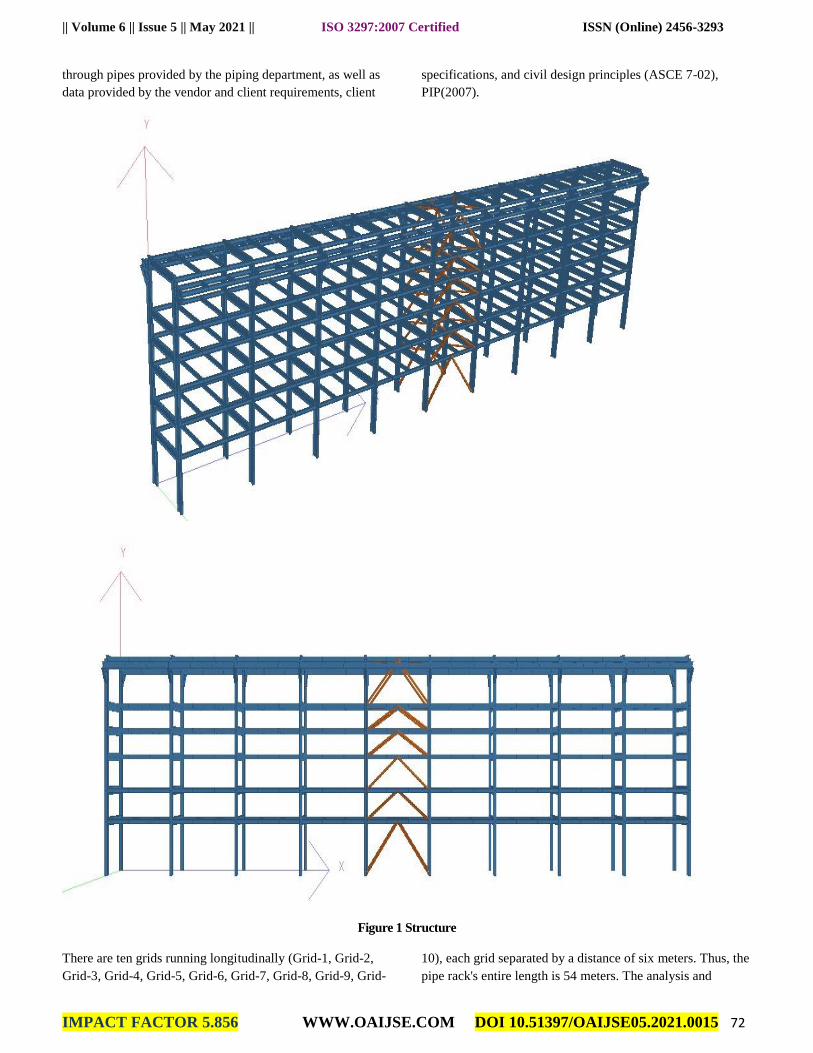
Figure 1 Structure
There are ten grids running longitudinally (Grid-1, Grid-2,
Grid-3, Grid-4, Grid-5, Grid-6, Grid-7, Grid-8, Grid-9, Grid-
10), each grid separated by a distance of six meters. Thus, the
pipe rack's entire length is 54 meters. The analysis and
|| Volume 6 || Issue 5 || May 2021 || ISO 3297:2007 Certified ISSN (Online) 2456-3293
IMPACT FACTOR 5.856 WWW.OAIJSE.COM DOI 10.51397/OAIJSE05.2021.0015 74
assembly of beams, columns, and bracings (longitudinal,
intermediate, horizontal, and plan) has been completed, and
STAAD assembly images are supplied above.
1) Central bay has been considered as the anchor bay.
2) Plane bracing and vertical bracing are included to meet
design requirements and to provide clearance for pipe
routing.
3) Supports for cable trays are supplied at a maximum
spacing of 3m.
4) The columns are oriented and arranged in accordance with
their maximal moment of inertia.
5) Due to the pipe rack's width exceeding 4m in both bays.
Thus, both bays are accessible to humans below the lower
decks.
6) The biggest pipe diameter 30" passes through Tier-1 Grid-
8; the load is supported by the universal beam
UB610X305X149.
7) Moment and shear connections are supplied in accordance
with the column and beam's design specifications.
8) Vertical bracing is provided between Grid-5 and Grid-6 to
accommodate the passage of 18" and 24" diameter pipes and
cable trays through these grids.
II DESIGN METHODOLOGY
The design of the pipe rack is done on the basis of the
standard load data given from the mechanical and piping
department. The design is followed as per the specifications
from the ASCE 07 and PIP(2007)STC PIP 01015.However
the design may also depends upon the
1) Clients financial status and estimation,
2) The pipe rack local environment conditions,
3) Clients specifications, civil design basis.
4) Mechanical load, General arrangement drawings.
5).From the data given from vendor.
Design Loads Considered And Code Specifications For
These Loads:-
1)Dead Load –DL: Superstructure weight consisting of self-
weight of the structural steel members, handrails & grating
weight shall be considered as dead load. The grating self
weight shall be considered as 0.5 kN/m2.Additional load of
12% of the self-weight of structure shall be considered
towards connection plates.
2) Live Load –LL: Live loads on the platforms, walkways
and staircase are to be considered based on the usage and
from design basis.
3) Fire Proofing Load –FP: The weight of fire proofing
material applied to protect the structure against fire hazards
shall be taken into account. Fireproofing weights shall be
determined based on 34mm thick Fendolite -MII (Unit weight
= 7 kN/m3) applied in the shape of the steel profile for sizes
more than 200mm (in either dimension). For steel profile of
sizes 200mm or less solid fill shall be considered.
Fireproofing shall be provided based on fire hazard
assessments. This load shall be included in DL case.
4)Pipe Empty Load –PE: The Blanket load of 1.1 kN/m2for
pipes less than 12 inch and actual empty weight for pipes
greater than or equal to 12inch as given by piping discipline.
5)Pipe Operation Load –PO: The Blanket load of
0.6Kn/m2for pipes less than 12 inch and actual content
weight for pipes greater than or equal to 12inch as given by
piping discipline.
6)Pipe Hydro Test Load –PT:PT is the weight of water in the
pipe during the hydro-test. For hydro-test it is assumed that
the two largest pipe sizes per tier on the rack are tested at the
same time. All other lines are considered empty. For pipes
less than12 inch diameter, a uniformly distributed load of 0.6
kN/m2may be considered when a more definitive value for
the weight of water in the pipes cannot be established. The
loads from the weight of water in the lines of 12 inch
diameter and above shall be applied as concentrated loads at
the pipe locations as given on the piping layouts and load
data.
7)Longitudinal Pipe Friction Forces (PFL):A longitudinal
horizontal force due to pipe friction equal to 10% of the pipe
operating weight (empty pipes + pipe contents) shall be
applied on each pipe supporting beam of the pipe rack. For
small bore lines (less than 12 inch dia) above loads shall be
taken as uniformly distributed. The friction loads shall be
considered to be acting at the respective pipe locations on the
beam.
8)Transverse Pipe Friction Forces (PFT):A transverse
horizontal force due to friction equal to 5% of the pipe
operating weight (empty pipes + pipe contents) shall be
applied on each pipe supporting beams of the pipe rack. For
small bore lines (less than 12 inch dia) above loads shall be
taken as uniformly distributed.
|| Volume 6 || Issue 5 || May 2021 || ISO 3297:2007 Certified ISSN (Online) 2456-3293
IMPACT FACTOR 5.856 WWW.OAIJSE.COM DOI 10.51397/OAIJSE05.2021.0015 75
9) Pipe Anchor Forces -PAL & PAT: Longitudinal and
transverse anchor/guide forces (PAL & PAT) shall be the
greater of:
a) Loads as specified by Piping Department based on stress
analysis results.
b) Longitudinal anchor load (PAL) equal to 10% of the pipe
operating (empty pipes + pipe contents) weight per tier and
transverse anchor load (PAT) equal to5% of the pipe
operating weight per tier.
III WIND LOADS ON PIPE RACK
A. Wind on Pipe rack
Find loads on pipe rack frame members shall be calculated
using a pressure coefficient (Ct) of 1.2 for circular sections
less than 150 mm diameter, 0.8 for circular sections greater
than or equal to 150 mm diameter and 2.0 for flat shapes and
rolled structural shapes. The effect of increased width / depth
of member size due to fireproofing shall be accounted for.
Normal wind forces shall be considered to act during the
hydro-testing of the pipes.
Transverse Wind Loads (WT) on Cable Trays
Wind load on the cable trays at each tier shall be determined
as follows:
Fdesign = qh*Ct*D*Lt
Where,
qh = Design wind pressure at height
hCt = 2 + B/(25*D) ≤ 4
B = Total width across cable trays
D = depth of cable tray
Lt =the tributary length of cable trays
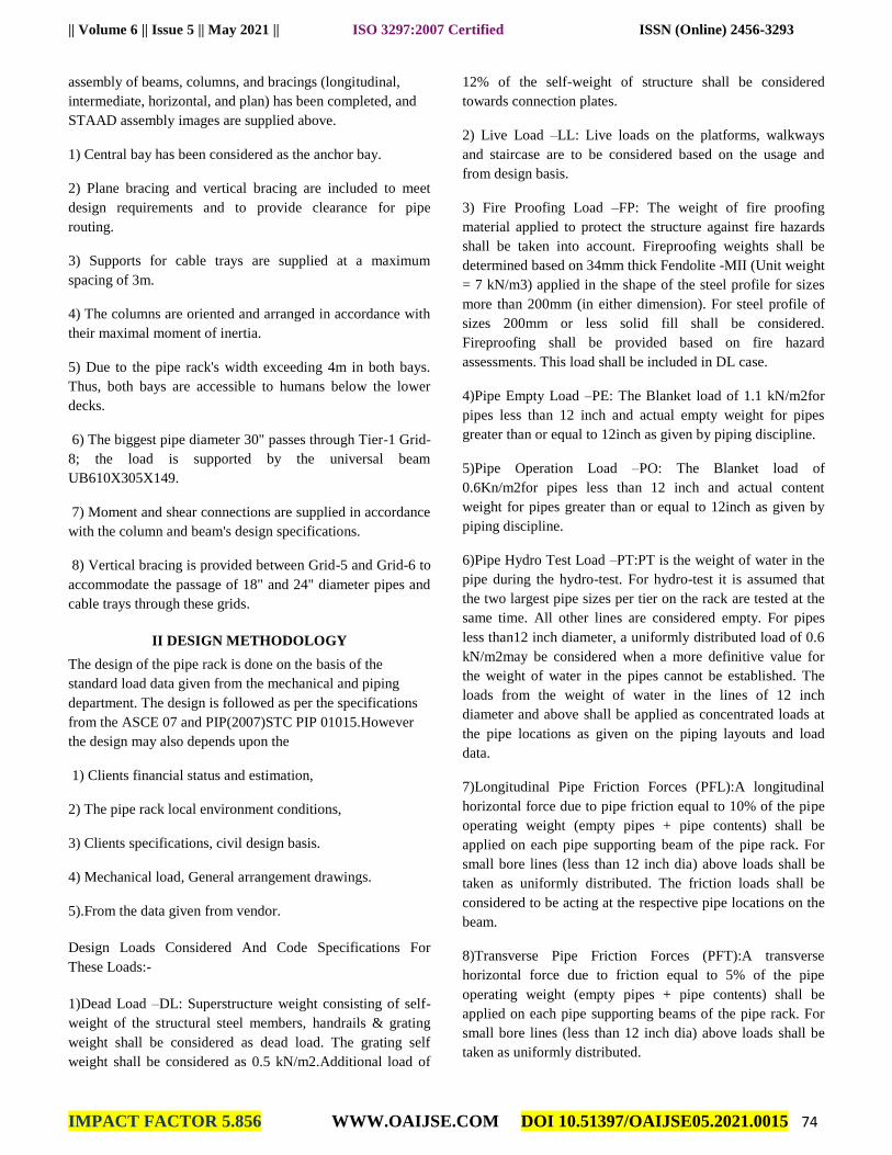
IV RESULTS AND DISCUSSION
The pipe rack is a global pipe rack project based in Saudi
Arabia. This pipe rack is constructed in accordance with the
provisions and standards of ASCE 7-05 as well as
PIP(2007)PIP STC01015 and is modelled in STAAD PRO
V8i software. The ASCE guideline should be regarded as a
reference manual, not as a design manual. The STAAD PRO
V8i programme analysed this pipe rack using the LRFD
(Load Resistant Factor Design) approach specified in the
AISC 360-10.
Figure 1 Model
|| Volume 6 || Issue 5 || May 2021 || ISO 3297:2007 Certified ISSN (Online) 2456-3293
IMPACT FACTOR 5.856 WWW.OAIJSE.COM DOI 10.51397/OAIJSE05.2021.0015 75
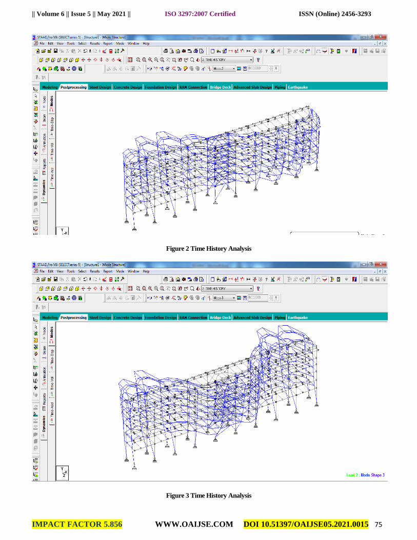
Figure 2 Time History Analysis
Figure 3 Time History Analysis
|| Volume 6 || Issue 5 || May 2021 || ISO 3297:2007 Certified ISSN (Online) 2456-3293
IMPACT FACTOR 5.856 WWW.OAIJSE.COM DOI 10.51397/OAIJSE05.2021.0015 76
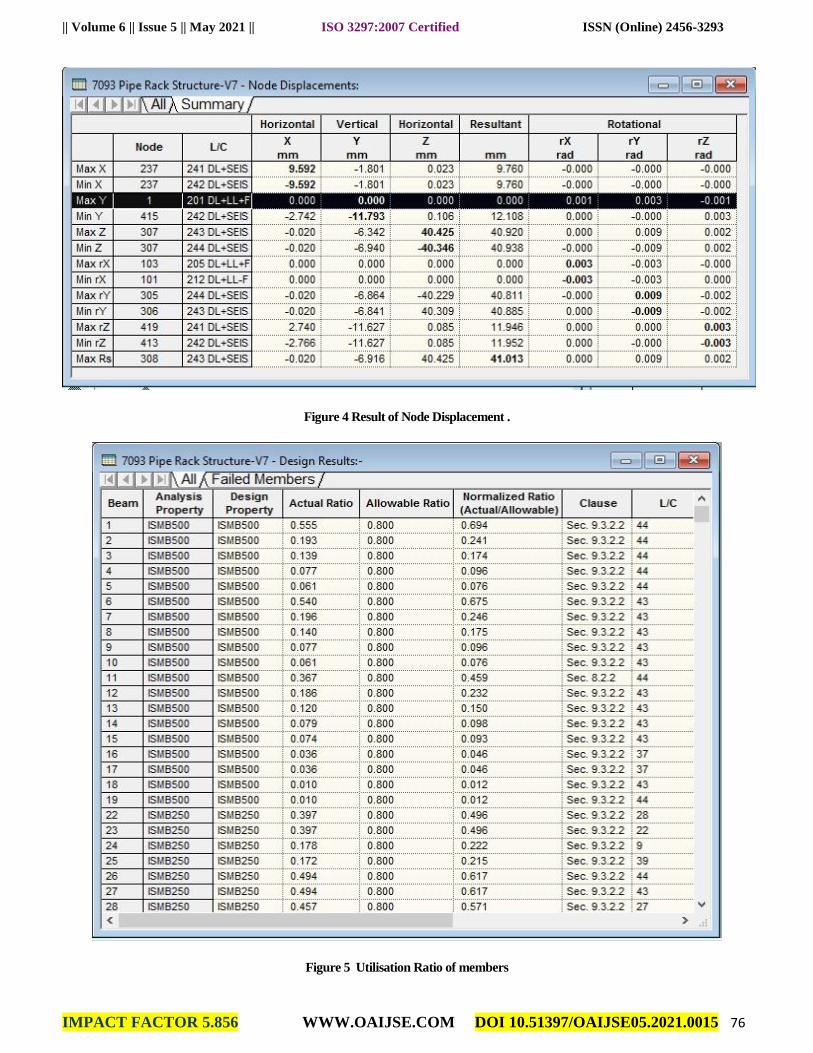
Figure 4 Result of Node Displacement .
Figure 5 Utilisation Ratio of members
|| Volume 6 || Issue 5 || May 2021 || ISO 3297:2007 Certified ISSN (Online) 2456-3293
IMPACT FACTOR 5.856 WWW.OAIJSE.COM DOI 10.51397/OAIJSE05.2021.0015 77
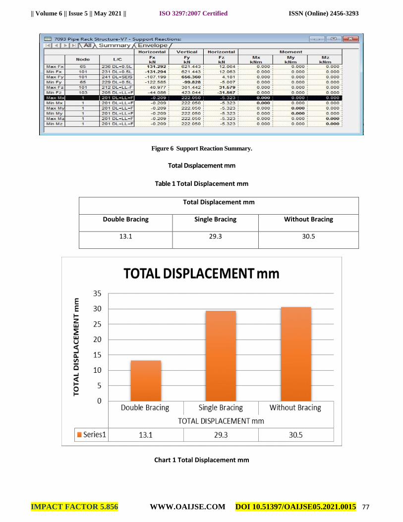
Figure 6 Support Reaction Summary.
Total Dısplacement mm
Table 1 Total Displacement mm
Total Displacement mm
Double Bracing Single Bracing Without Bracing
13.1 29.3 30.5
Chart 1 Total Displacement mm
|| Volume 6 || Issue 5 || May 2021 || ISO 3297:2007 Certified ISSN (Online) 2456-3293
IMPACT FACTOR 5.856 WWW.OAIJSE.COM DOI 10.51397/OAIJSE05.2021.0015 78
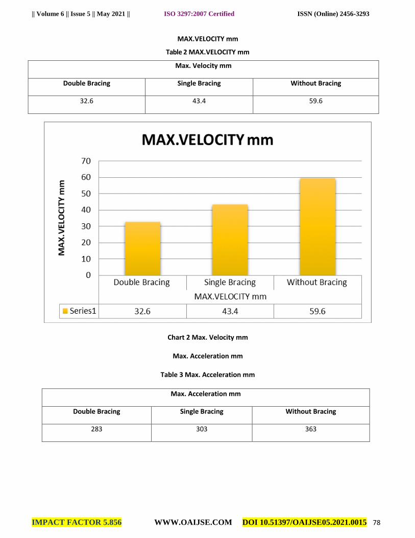
MAX.VELOCITY mm
Table 2 MAX.VELOCITY mm
Max. Velocity mm
Double Bracing Single Bracing Without Bracing
32.6 43.4 59.6
Chart 2 Max. Velocity mm
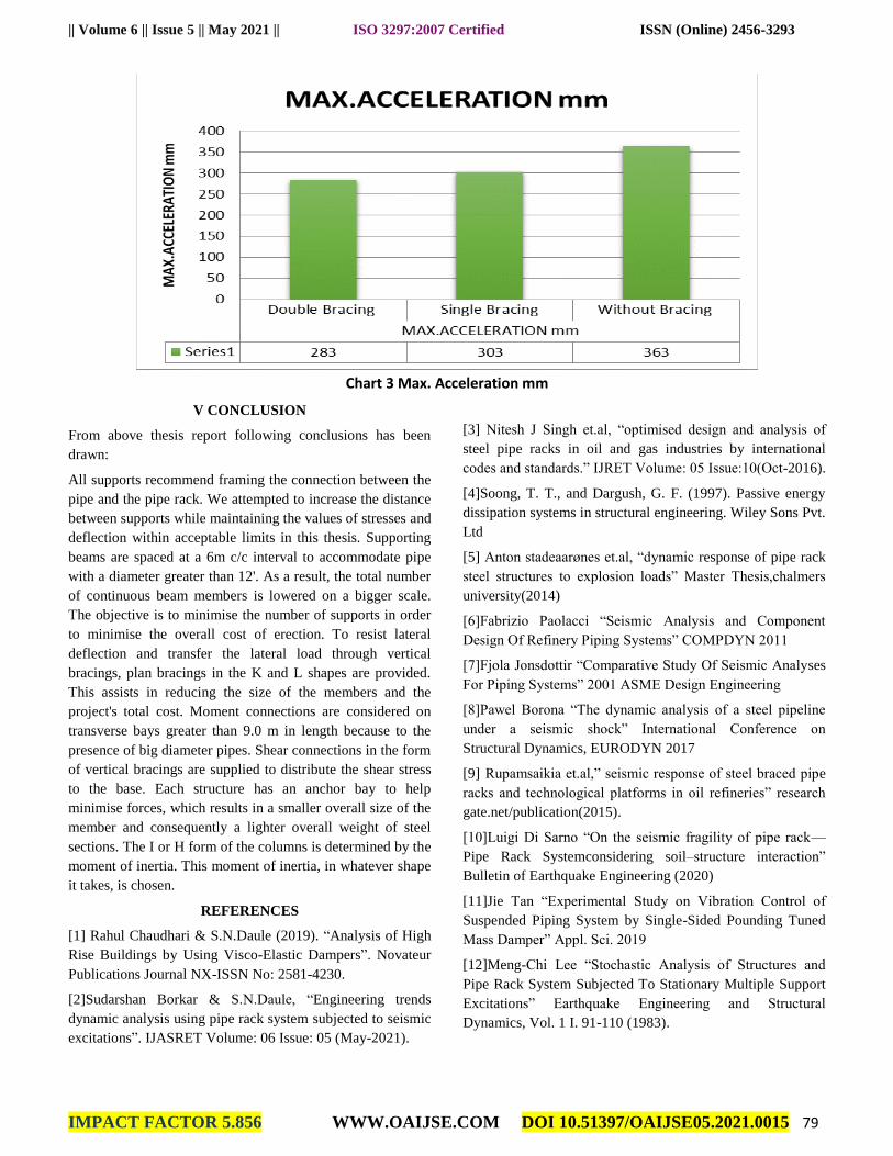
Max. Acceleration mm
Table 3 Max. Acceleration mm
Max. Acceleration mm
Double Bracing Single Bracing Without Bracing
283 303 363
|| Volume 6 || Issue 5 || May 2021 || ISO 3297:2007 Certified ISSN (Online) 2456-3293
IMPACT FACTOR 5.856 WWW.OAIJSE.COM DOI 10.51397/OAIJSE05.2021.0015 79
Chart 3 Max. Acceleration mm
V CONCLUSION
From above thesis report following conclusions has been
drawn:
All supports recommend framing the connection between the
pipe and the pipe rack. We attempted to increase the distance
between supports while maintaining the values of stresses and
deflection within acceptable limits in this thesis. Supporting
beams are spaced at a 6m c/c interval to accommodate pipe
with a diameter greater than 12'. As a result, the total number
of continuous beam members is lowered on a bigger scale.
The objective is to minimise the number of supports in order
to minimise the overall cost of erection. To resist lateral
deflection and transfer the lateral load through vertical
bracings, plan bracings in the K and L shapes are provided.
This assists in reducing the size of the members and the
project's total cost. Moment connections are considered on
transverse bays greater than 9.0 m in length because to the
presence of big diameter pipes. Shear connections in the form
of vertical bracings are supplied to distribute the shear stress
to the base. Each structure has an anchor bay to help
minimise forces, which results in a smaller overall size of the
member and consequently a lighter overall weight of steel
sections. The I or H form of the columns is determined by the
moment of inertia. This moment of inertia, in whatever shape
it takes, is chosen.
REFERENCES
[1] Rahul Chaudhari & S.N.Daule (2019). “Analysis of High
Rise Buildings by Using Visco-Elastic Dampers”. Novateur
Publications Journal NX-ISSN No: 2581-4230.
[2]Sudarshan Borkar & S.N.Daule, “Engineering trends
dynamic analysis using pipe rack system subjected to seismic
excitations”. IJASRET Volume: 06 Issue: 05 (May-2021).
[3] Nitesh J Singh et.al, “optimised design and analysis of
steel pipe racks in oil and gas industries by international
codes and standards.” IJRET Volume: 05 Issue:10(Oct-2016).
[4]Soong, T. T., and Dargush, G. F. (1997). Passive energy
dissipation systems in structural engineering. Wiley Sons Pvt.
Ltd
[5] Anton stadeaarønes et.al, “dynamic response of pipe rack
steel structures to explosion loads” Master Thesis,chalmers
university(2014)
[6]Fabrizio Paolacci “Seismic Analysis and Component
Design Of Refinery Piping Systems” COMPDYN 2011
[7]Fjola Jonsdottir “Comparative Study Of Seismic Analyses
For Piping Systems” 2001 ASME Design Engineering
[8]Pawel Borona “The dynamic analysis of a steel pipeline
under a seismic shock” International Conference on
Structural Dynamics, EURODYN 2017
[9] Rupamsaikia et.al,” seismic response of steel braced pipe
racks and technological platforms in oil refineries” research
gate.net/publication(2015).
[10]Luigi Di Sarno “On the seismic fragility of pipe rack—
Pipe Rack Systemconsidering soil–structure interaction”
Bulletin of Earthquake Engineering (2020)
[11]Jie Tan “Experimental Study on Vibration Control of
Suspended Piping System by Single-Sided Pounding Tuned
Mass Damper” Appl. Sci. 2019
[12]Meng-Chi Lee “Stochastic Analysis of Structures and
Pipe Rack System Subjected To Stationary Multiple Support
Excitations” Earthquake Engineering and Structural
Dynamics, Vol. 1 I. 91-110 (1983).
Related Documents