DYNAMIC ANALYSIS OF A ROTARY HOLLOW SHAFT WITH HOT-FIT PART USING CONTACT ELEMENTS WITH FRICTION Shin-Yong Chen 1 , Chieh Kung 2 , Jung-Chun Hsu 3 Far East University, Tainan County, Taiwan, R.O.C. E-mail: 1 [email protected]; 2 [email protected]; 3 [email protected] Received February 2011, Accepted July 2011 No. 11-CSME-19, E.I.C. Accession 3259 ABSTRACT One of the key factors in designing a motor built-in high speed spindle is to assemble the motor rotor and shaft by means of hot-fit. Presented in this paper is a study of the influence of a hot-fit rotor on the local stiffness of the hollow shaft. Dynamic analyses of the rotor-hollow shaft assembly using contact elements are conducted. The normal contact stress state between the rotor and the hollow shaft is obtained through the use of contact elements with friction effects included. The normal contact stress, considered as the pr-stress between the rotor and the hollow shaft, is then adopted for subsequent modal analyses. In this study, the modal analysis results are verified by a modal testing experiment. The percent errors of the first natural frequency and the second natural frequency are down to about 0.58% and 0.79%, respectively. Keywords: high speed spindle; motor rotor; hot-fit; contact element with friction. ANALYSE DYNAMIQUE D’UN ARBRE ROTATIF CREUX A ` AJUSTEMENT DE PIE ` CES PAR PRESSAGE A ` CHAUD UTILISANT LE CONTACT AVEC FROTTEMENT RE ´ SUME ´ Un des e ´le ´ments cle ´s dans la conception d’un moteur de broche inte ´gre ´ pour grande vitesse est l’assemblage du rotor et de l’arbre par pressage a ` chaud. L’e ´tude porte sur l’influence d’un rotor a ` ajustement par pressage a ` chaud sur la raideur locale de l’arbre rotatif creux. Des analyses dynamiques de l’assemblage de l’arbre rotatif creux et du rotor utilisant le contact des e ´le ´ments avec frottement sont effectue ´es. La contrainte de contact normal entre le rotor et l’arbre creux est obtenue par le contact des e ´le ´ments avec effets de frottement. . La contrainte de contact normal, conside ´re ´ comme la pre ´contrainte entre le rotor et l’arbre creux, est alors utilise ´e pour l’analyse de mode `le subse ´quent. Dans cette e ´tude, les re ´sultats d’analyse de mode `le sont ve ´rifie ´s par des tests. Le pourcentage d’erreurs de la premie `re fre ´quence naturelle et de la deuxie `me a diminue ´ jusqu’a ` approximativement 0.58% et 0.79% respectivement. Mots-cle ´s: arbre rotatif a ` haute vitesse; rotor du moteur; e ´le ´ment de contact avec frottement. Transactions of the Canadian Society for Mechanical Engineering, Vol. 35, No. 3, 2011 461

Welcome message from author
This document is posted to help you gain knowledge. Please leave a comment to let me know what you think about it! Share it to your friends and learn new things together.
Transcript

DYNAMIC ANALYSIS OF A ROTARY HOLLOW SHAFT WITH HOT-FIT PARTUSING CONTACT ELEMENTS WITH FRICTION
Shin-Yong Chen1, Chieh Kung2, Jung-Chun Hsu3
Far East University, Tainan County, Taiwan, R.O.C.
E-mail: [email protected]; [email protected]; [email protected]
Received February 2011, Accepted July 2011
No. 11-CSME-19, E.I.C. Accession 3259
ABSTRACT
One of the key factors in designing a motor built-in high speed spindle is to assemble themotor rotor and shaft by means of hot-fit. Presented in this paper is a study of the influence of ahot-fit rotor on the local stiffness of the hollow shaft. Dynamic analyses of the rotor-hollowshaft assembly using contact elements are conducted. The normal contact stress state betweenthe rotor and the hollow shaft is obtained through the use of contact elements with frictioneffects included. The normal contact stress, considered as the pr-stress between the rotor andthe hollow shaft, is then adopted for subsequent modal analyses. In this study, the modalanalysis results are verified by a modal testing experiment. The percent errors of the first naturalfrequency and the second natural frequency are down to about 0.58% and 0.79%, respectively.
Keywords: high speed spindle; motor rotor; hot-fit; contact element with friction.
ANALYSE DYNAMIQUE D’UN ARBRE ROTATIF CREUX A AJUSTEMENT DEPIECES PAR PRESSAGE A CHAUD UTILISANT LE CONTACT AVEC
FROTTEMENT
RESUME
Un des elements cles dans la conception d’un moteur de broche integre pour grande vitesseest l’assemblage du rotor et de l’arbre par pressage a chaud. L’etude porte sur l’influence d’unrotor a ajustement par pressage a chaud sur la raideur locale de l’arbre rotatif creux. Desanalyses dynamiques de l’assemblage de l’arbre rotatif creux et du rotor utilisant le contact deselements avec frottement sont effectuees. La contrainte de contact normal entre le rotor etl’arbre creux est obtenue par le contact des elements avec effets de frottement. . La contrainte decontact normal, considere comme la precontrainte entre le rotor et l’arbre creux, est alorsutilisee pour l’analyse de modele subsequent. Dans cette etude, les resultats d’analyse de modelesont verifies par des tests. Le pourcentage d’erreurs de la premiere frequence naturelle et de ladeuxieme a diminue jusqu’a approximativement 0.58% et 0.79% respectivement.
Mots-cles: arbre rotatif a haute vitesse; rotor du moteur; element de contact avec frottement.
Transactions of the Canadian Society for Mechanical Engineering, Vol. 35, No. 3, 2011 461

1. INTRODUCTION
As the modern world progresses, the demand on products has asked more about theirfunctionality than their appearance. The finite element method (FEM) is a powerful tool and hasbeen applied to numerous analyses. One advantage of FEM is that it could save time and cost forengineers in the development of new products. In the beginning of the research and developmentof a product, the finite element model of the product is constructed and static and dynamicanalyses are conducted on the model to obtain the simulation results as the first engineeringassessments. Experiences have indicated that the selected parameters of the numerical model suchas element type, material model, contact conditions, etc. might introduce errors to the simulatedresults. Thus, the numerical model needs to be verified by experimental means; for example, anumerical modal analysis should be further verified by the results of a modal testing. In modaltesting, the frequency response function (FRF) and modal parameters are obtained and used as abenchmark for the finite element model on subsequent dynamical analyses.
There were many studies about modifying finite element model based on experimental results.While most of the studies were based on homogeneous governing equations and orthogonalityconditions of a specific structural system, some considered the effects of modal parameterson mass and stiffness matrices as well as sensitivity analysis. In the Berman’s study [1], theexperimental eigenvalue matrix and modal matrix were used to modify the mass and stiffnessmatrices of the system. The modified matrices were still full thus were incompatible with thefinite element model. Chen [2] proposed a procedure to identify the structural parameters bymodal testing results. In the procedure, the eigenvalue matrix, modal matrix, and the calculatedeigenvalue matrix were used to modify the physical parameters of the structure. Yee and Tsuei[3] suggested an approach of directly modifying the mass and stiffness matrices obtainedthrough the modal simulation. In the studies by Chen, Tsuei and Ibrahim [4–7], normalizedmode shapes were extracted from complex modes as the experiment bases of an undampedvibration theory. A dynamic reduction approach was suggested to reduce the degrees offreedom hence confirm the model with the results of modal testing. The model was furthermodified based on the approaches suggested by Shih and Tsuei [8].
NOMENCLATURE
f externally applied excitation vector in time domainK stiffness matrixM mass matrixX displacement response vector in frequency domainF externally applied excitation vector in frequency domainh frequency response functionp contact pressuret timex displacement response vector in time domaint shear stressm friction coefficientw normal mode shape vectorv circular frequency�vvr natural frequency of a system
Transactions of the Canadian Society for Mechanical Engineering, Vol. 35, No. 3, 2011 462

In the studies by Ozsahin, Erturk and Ozguven [9–11], analyses on a spindle-holder-toolassembly were conducted. The Timoshenko beam theory was employed to calculate the tool pointFRF of the assembly with the use of the receptance coupling and structural modificationmethods. The model was important to the assessment of cutting Stability Lobe Diagram. Intheir studies, the dynamic parameters in the interfaces of spindle- holder and holder-tool sub-assemblies were also assessed. The stiffness in the interface was determined with the modal testingresults. The model was updated with the stiffness and the analysis results were well agreed withthose of modal testing. Their studies also investigated the design parameters including overalldimensions, bearing stiffness, bearing position, damping, tool holder, and tool overhang. Afundamental issue came from their study was the precision of the finite element model of therotor-shaft assembly as a structural system. As the model of the rotor-shaft assembly is preciselyconstructed, it would improve prediction of the whole shaft structure including other accessoriessuch as bearing, etc. This issue is the major investigation of the study presented herein.
The dynamic analysis of the rotating shaft is one key factor in the development of a motorbuilt-in high speed spindle. However, one of the important design factors is that the motor rotoris mounted on the shaft by hot-fit (shrink). This fitting complicates the connection of the rotorand the shaft. To establish an accurate finite element model becomes a direction that is worthfurther investigation. While most previous studies focused on the design and functionalities ofthe spindle system as a whole, few were on the structural behavior of the rotor-shaft assembly[12–15]. These studies adopted finite element tool to build the rotor-shaft assembly with solidelements. Contact conditions in the interface of rotor and shaft were not considered. Theaccuracy of the results was yet to be verified. Chen [16–18] indicated that the overall stiffness ofa spindle was considerably influenced by the fitted rotor. The natural frequencies tend toincrease with the rotor mounted on the shaft by interference fit. Ignoring the contactmechanism (only considering mass inertia) in the interface of rotor and shaft wouldunderestimate the dynamic characteristics of the rotor-shaft assembly. On the other hand, ifthe rotor and the shaft are ‘‘perfectly stiff contact’’, the stiffness of the assembled structurewould become even higher which would present overestimated results.
In the studies of Ju, Stone, and Rowlands [19–20], the penalty function method was used forcontact analysis. The penalty function method is suitable for large distorted elements, friction,and augmented Lagrangian algoritnm. Asante [21] applied elastic contact and finite elementmodel to predicting the distributions of applied pressures as well as stresses and strains in aclamping system. In his research, the magnitude of the applied pressures was not accessed. Theamount of interference was varied to study its effects. In addition, other researches [22–28]introduced contact elements to the study of finite element modeling as well as boundary elementmodeling. These studies focused more on frictional effects including loads and contact stressesthan interference. In this study, contact elements are used for the analysis of the rotor-shaftsystem. The study consists of a static analysis followed by a modal analysis. The stiffness of thesystem is investigated in terms of interference and frequency. This study is original in that therotor and the shaft are assembled with interference fit and that contact elements are alsointroduced to modeling the behavior between the rotor and the shaft. The approach is anapplication to design phase rather a posterior improvement proposed in [16–18].
2. APPROACHES FOR THE STUDY
In this study, commercial finite element analysis software, ANSYS, is employed to constructthe numerical model of rotor-shaft assembly and to perform modal analyses. The simulated
Transactions of the Canadian Society for Mechanical Engineering, Vol. 35, No. 3, 2011 463

results are further verified by those obtained through modal testing. In constructing thenumerical model, the contact elements supported by the software are deployed in the interfaceof the hollow shaft and the rotor. In a numerical analysis, contact due to interference fit ischaracterized by contact status between the components involved in contact. It has suchfeatures as no penetration, transferring of normal pressure and tangential traction, inexistenceof normal tension force. These features are nonlinear and complicated for the analysis.
Contact problems require significant computer resources to be solved. It is essential tounderstand the physics of the problem and set up proper model to efficiently solve the problem.There are two significant difficulties in handling contact problems. First, it is not known asa priori the regions of contact until the problem is being solved. Depending on the loads,material, boundary conditions, and other factors, surfaces can come into and go out of contactwith each other in a largely unpredictable and abrupt manner. Second, most contact problemsneed to account for friction. There are several friction laws and models to choose from, and allare nonlinear. Frictional responses can be chaotic, making solution convergence difficult.
Contact problems fall into two general classes: rigid-to-flexible and flexible-to-flexible. Inrigid-to-flexible contact problems, one or more of the contacting surfaces are treated as rigid(i.e., it has a much higher stiffness relative to the deformable body it contacts). In general, whena soft material comes in contact with a hard material, the problem may be assumed to be rigid-to-flexible. Many metal forming problems fall into this category. The other class, flexible-to-flexible, is the more common type. In this case, both contacting bodies are deformable and havesimilar stiffness. In this study, the rotor-shaft assembly is considered flexible-to-flexible contactas they are all deformable.
ANSYS supports three contact models: node-to-node, node-to-surface, and surface-to-surface. Each type of model uses a different set of ANSYS contact elements. This study adopts3D surface-to-surface model to study the dynamic characters of a rotor-shaft assembly. Thefinite element model of the assembly is first constructed. The contact pairs are then identified byusing target and contact elements; namely TARGE170 and CONTA174. CONTA174 is anelement representing contact and sliding between 3-D "target" surfaces and a deformablesurface, defined by this element. The 3-D "target" surface is represented by TARGE170.CONTA174 has the same geometric characteristics as the solid or shell element face with which
Fig. 1. The schematic of the apparatus of modal testing.
Transactions of the Canadian Society for Mechanical Engineering, Vol. 35, No. 3, 2011 464

it is connected. Contact occurs when the element surface penetrates one of the target segmentelements. Before the contact and target elements are deployed, contact and target surfaces mustbe designated. In general, a concave surface, a stiffer surface or a surface having coarse meshshould be the target surface [29]; thus, the inner surface of the rotor is designated as the targetsurface. Contrarily, the outer surface of the hollow shaft is the contact surface. The contactelements associated with flexible surfaces have the same geometric features as those of theunderlying deformable elements. In addition, the contact elements are in the same order as thatof the underlying deformable elements.
It is necessary to define stiffness for all contact problems. The amount of penetration betweencontact and target surfaces depends on the normal stiffness. Higher stiffness values can lead toconvergence difficulties. In general, the contact stiffness should be large enough to ensure thesmallest penetration and small enough to ensure convergence. ANSYS is capable of estimatingthe contact stiffness based on the material properties of the deformed elements. It employsFKN, a necessary normal contact stiffness factor which scales the contact stiffness as a fractionof the Young’s modulus of the underlying material, to control the contact behavior between thecontact and target elements. The usual scaling range of FKN is 0.01,10. In the analysis, FKNis set 1.0 which is appropriate for bulk deformation and for avoiding penetration. In this studyCoulomb friction model is used; that is, the contacting surfaces carry shear stresses up to acertain magnitude across their interface before they start sliding relative to each other. Coulombfriction model defines an equivalent shear stress as a fraction of the contact pressure. Once the
Fig. 2. Flow chart of the analysis.
Fig. 3. Schematic of the spindle.
Transactions of the Canadian Society for Mechanical Engineering, Vol. 35, No. 3, 2011 465

shear stress is exceeded, the two surfaces will slide relative to each other. In the analysis
t~m|p ð1Þ
where t is the shear stress, m is the friction coefficient, and p is the contact pressure.
The boundary condition of the specimen used for the modal testing is of ‘‘soft suspension’’and is an approximately ideal free-free boundary condition. Generally, it is infeasible to reach acondition of free vibration in a modal testing; soft suspension therefore becomes a reasonableapproach. In this study, the rotor-shaft assembly is suspended with rubber bands in the modaltesting. The height of suspension is half of the free length of the rubber band. A modal testingaims at assuring modal parameters including natural frequencies, mode shapes, and dampingratios. The test apparatus consists of an excitation source, a signal acquisition device, a signalanalyzer, and frequency response analyzer. The mode shapes corresponding to the naturalfrequencies are obtained based on the frequency response functions derived at pre-selectedlocations of the tested specimen. It is noted that the mode shape is a relatively vibratorymeasure between the locations of a structure and is invariant with the test conditions and testmethods. Figure 1 shows the diagram of experiment apparatus.
In a dynamic analysis, the frequency response function (FRF) is used as a quantitativemeasure to characterize the structural system to be analyzed. In general, the FRF is derived foran undamped dynamic system. The governing equation of the motion of an undamped dynamicsystem is
M€xx(t)zKx(t)~f(t) ð2Þ
where M, K, x, and f, respectively, are the mass matrix, stiffness matrix, displacement responsevector and externally applied excitation vector of the dynamic system. The detailed derivationscan be referred in [18]. With zero initial conditions, the displacement response evaluated infrequency domain is expressed as
Fig. 4. Schematic of the rotor.
Table 1. Sectional dimensions of the spindle and the rotor.
Dimension Length (mm) Dimension Diameter(mm)
A 71.62 D 23.963B 79.95 E 15.043C 98.13 F 24.005G 79.95 H 23.977
I 39.500
Transactions of the Canadian Society for Mechanical Engineering, Vol. 35, No. 3, 2011 466

X(v)~H(v)F(v) ð3Þ
where X and F, respectively, are Laplace transformation of the displacement and the appliedexcitations, and
H(v)~ K{v2M� �{1 ð4Þ
is denoted as the normal FRF. Furthermore, we obtain
hjk(v)~XN
r~1
(rwj)(rwk)
�vv2r{v2
ð5Þ
in which hjk is the FRF of j-th node responding to the excitation at the k-th node, rwj is the j-thcomponent of the r-th mode shape vector, �vvr is the r-th natural frequency of the system, andN is number of the total natural frequencies considered in calculating the response. In thepresent study, we obtain both rwj and �vvr through FEA. The frequency response functions aredetermined using Eq. (4) and then compared with those obtained by the modal testing.
3. APPLICATION AND RESULTS3.1. Finite Element Modeling
The flow of this study is expressed in Fig. 2. First, an interference of 0.028 mm is initiallyselected. With this interference, the hollow shaft and the rotor are designed as seen in Figs. 3
Fig. 5. The mesh of the finite element model of the rotor-shaft system.
Fig. 6. Distribution of deformations in radial direction in the shaft.
Transactions of the Canadian Society for Mechanical Engineering, Vol. 35, No. 3, 2011 467

and 4, respectively. Table 1 lists the associated dimensions of the hollow shaft and the rotor. Itis noted that Dimension A, 71.62 mm, is the distance between the left ends of the shaft and therotor. Dimensions B and G, as seen in Figs. 3 and 4 and Table 1, corresponds to the length ofthe rotor. The finite element model of the rotor-shaft assembly is constructed and the meshes ofthe model are shown in Fig. 5. To facilitate subsequent contact analyses, the FE model ismanually meshed in a uniform pattern with the element size 2 mm longitudinally, 1 mmradially, and 28 divisions circumferentially. The material properties are the same for both shaftand rotor with Young’s modulus 2.161011 N/m2, density 7950 kg/m3, and Poisson’s ratio 0.333,respectively. For the FE model, SOLID95 elements are employed to describe the behavior ofboth shaft and rotor; SOLID95 is a 3D 20-node solid structural element. It has compatibledisplacement shape and is well suited to model curved boundaries. CONTA174 andTARGE170 are used in the contact area of the interference to fully catch the contactresponses. The inner surface of the rotor is set to be the contact surface while the segment of theouter surface of the shaft that interferes with the rotor is set to be the target surface. It isassumed that both surfaces are perfectly contacted. The sparse matrix direct solver is selected.Additional settings required for this contact analysis include (1) the augmented Lagrange
Fig. 7. Distribution of deformations in radial direction in the rotor-shaft assembly.
Fig. 8. Distribution of normal stresses in radial direction in the rotor-shaft assembly.
Transactions of the Canadian Society for Mechanical Engineering, Vol. 35, No. 3, 2011 468

method, which can lead to better conditioning and is less sensitive to the magnitude of thecontact stiffness coefficient, is chosen as contact formulation, (2) contact detection is located atGauss integration point, (3) initial penetrations including geometry penetration and offset, (4)contact stiffness being updated based on the current mean stress of the underlying elements, (5)normal penalty stiffness factor 1, and (6) penetration tolerance factor 0.1. For static analysis,both end surfaces of the shaft are fixed as the fixed-fixed BCs to prevent rigid body motion andto comply with Saint-Venant’s principle. For modal analysis, free-free BCs are used in order forthe model to be compatible with that in the subsequent modal testing.
3.2. Results of Static Analysis without FrictionThe static analysis results of interest are presented in Figs. 6 through 8. Figure 6 shows the
radial deformation of the shaft. Most of the contact surface of the shaft deforms or shrinksuniformly. The deformation reveals lateral shrinkage due to interference fit. Neckingdeformation is seen in both entrant areas, i.e. the areas where the shaft meets both ends ofthe rotor. While shrinkage is seen on the shaft, there exists outward deflection on the rotor asshown in Fig. 7 which presents the radial deformations of the shaft and the rotor. It isinteresting to see from Fig. 7 that while most of the rotor body expands uniformly, apparentdeformations (in relative sense) exist at both ends of the rotor such that the rotor deforms in anozzle shape with a long throat. The described deformations result in stress concentration inboth entrant areas as shown in Fig. 8 which shows the normal stress distribution in radialdirection. Figure 8 also shows that the material in both overhangs of the shaft experiencetension stress and the material in the contact segment experience compression stress.
3.3. Dynamic Modal AnalysisThe pre-stress state obtained in the static analysis is then applied to the subsequent modal
analysis. The boundary condition used in the static analysis is cancelled so the rotor-shaftassembly is in free-free condition. The sparse matrix direct solver is selected. The first twonatural frequencies are 2053.3 Hz and 4312.26 Hz, respectively. The first vibratory mode shapeof the rotor-shaft assembly is shown in Fig. 9, and the second mode shape is in Fig. 10. Theresults of the mode shape are of expected as the first mode shape of the first mode is in a bowlshape with 2 nodal points and that of the second mode in ‘‘S’’ shape with 3 nodal points.
Fig. 9. The first mode shape of the rotor-shaft assembly.
Fig. 10. The second mode shape of the rotor-shaft assembly.
Transactions of the Canadian Society for Mechanical Engineering, Vol. 35, No. 3, 2011 469

3.4. Modal TestingTo verify the modal analysis of FEM results, the modal testing is conducted. In the specimen
of the test, an accelerometer is attached to the assembly at location 1 as shown in Fig. 11. The15 locations as marked 1 through 15 in Fig. 11 are the locations, each of which a hammer isused to create excitation. The responses of the rotor-shaft system subjected to the excitationsare analyzed to get the FRFs and then the natural frequencies are estimated by ME’scopeVESsoftware. The estimated first natural frequency is 2379.71 Hz, and the second natural frequencyis estimated to be 4849.32 Hz. Comparing the results of modal analysis of FEM and modaltesting, it is found the percent error of the first natural frequency is 13.7%, and the second11.1% as shown in Table 2.
3.5. Effects Of Contact FrictionIn the static analysis described above, the friction between contacting rotor and shaft is not
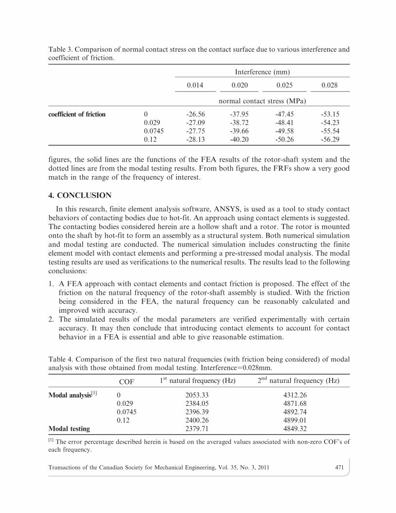
considered. In most applications, there indeed exists friction between any two contactingbodies. In common practice, the coefficient of friction on the interface between two steel parts is0.029,0.12. In the present study, three coefficients of friction (COF), 0.029, 0.0745, and 0.12,are assumed to study the effects of contact friction on the dynamic characteristics of the rotor-shaft assembly. The results of normal contact stress due to various interference and COF’s arepresented in Table 3. It is interesting to see from Table 3 that the normal contact stress increaseswith the coefficient of friction; for each interference, the normal contact stress for COF 5 0.029is about 2% higher than that for COF 5 0, 4.4% for COF 5 0.0745, and 5.9% for COF 5 0.12,respectively. Similar to the procedure described above, the pre-stress state with COF beingconsidered is then applied for the modal analysis to calculate the first two natural frequencies.The results are shown in Table 4. It can be seen from Table 4 that with the friction beingconsidered, the percent error of the first natural frequency becomes improved from 13.7% to0.58% (in average) and that of the second natural frequency from 11.1% to 0.79% (in average).Apart from the natural frequency, the frequency response functions (FRF) are also compared.The frequency response functions are obtained based on 0.028 mm interference andCOF50.0745. Shown in Fig. 12 is the comparison of the experimental FRF h1-1 with that ofthe FEA results, and in Fig. 13 the experimental FRF h15-1 with that of the FEA results. In the
Fig. 11. Fifteen locations where excitation is created by a hammer.
Table 2. Comparison of the natural frequencies obtained via modal analysis and modal testing.(interference 5 0.028 mm).
1st natural frequency (Hz) 2nd natural frequency (Hz)
Modal analysis 2053.33 4312.26Modal testing 2379.71 4849.32Percent error (%) 13.7 11.1
Transactions of the Canadian Society for Mechanical Engineering, Vol. 35, No. 3, 2011 470
figures, the solid lines are the functions of the FEA results of the rotor-shaft system and thedotted lines are from the modal testing results. From both figures, the FRFs show a very goodmatch in the range of the frequency of interest.
4. CONCLUSION
In this research, finite element analysis software, ANSYS, is used as a tool to study contactbehaviors of contacting bodies due to hot-fit. An approach using contact elements is suggested.The contacting bodies considered herein are a hollow shaft and a rotor. The rotor is mountedonto the shaft by hot-fit to form an assembly as a structural system. Both numerical simulationand modal testing are conducted. The numerical simulation includes constructing the finiteelement model with contact elements and performing a pre-stressed modal analysis. The modaltesting results are used as verifications to the numerical results. The results lead to the followingconclusions:
1. A FEA approach with contact elements and contact friction is proposed. The effect of thefriction on the natural frequency of the rotor-shaft assembly is studied. With the frictionbeing considered in the FEA, the natural frequency can be reasonably calculated andimproved with accuracy.
2. The simulated results of the modal parameters are verified experimentally with certainaccuracy. It may then conclude that introducing contact elements to account for contactbehavior in a FEA is essential and able to give reasonable estimation.
Table 3. Comparison of normal contact stress on the contact surface due to various interference andcoefficient of friction.
Interference (mm)
0.014 0.020 0.025 0.028
normal contact stress (MPa)
coefficient of friction 0 -26.56 -37.95 -47.45 -53.150.029 -27.09 -38.72 -48.41 -54.230.0745 -27.75 -39.66 -49.58 -55.540.12 -28.13 -40.20 -50.26 -56.29
Table 4. Comparison of the first two natural frequencies (with friction being considered) of modalanalysis with those obtained from modal testing. Interference50.028mm.
COF 1st natural frequency (Hz) 2nd natural frequency (Hz)
Modal analysis[1] 0 2053.33 4312.260.029 2384.05 4871.680.0745 2396.39 4892.740.12 2400.26 4899.01
Modal testing 2379.71 4849.32
[1] The error percentage described herein is based on the averaged values associated with non-zero COF’s ofeach frequency.
Transactions of the Canadian Society for Mechanical Engineering, Vol. 35, No. 3, 2011 471

Fig. 13. Comparison of the test FRF h15-1 with the numerical FRF. (Interference 5 0.028 mm, COF5 0.0745)
Fig. 12. Comparison of the test FRF h1-1 with the numerical FRF. (Interference 5 0.028 mm, COF5 0.0745)
Transactions of the Canadian Society for Mechanical Engineering, Vol. 35, No. 3, 2011 472

3. The approach proposed in the study is further verified with experimental results; thus, theapproach can then be considered as a design priori rather than a posteriori. Also, with theversatility of the procedure of the approach, it can be applicable to other similar contactanalyses.
Furthermore, the amount of interference might be varied in a rotor-shaft assembly due tonon-uniformly distributed temperature and the effects of centrifugal force; hence, the dynamicstiffness of the assembly is varied as well. This posts a future work of thermal-solid study thatmight lead to more precise results. It is believed that these more precise results would benefitanother future study in which simplified equivalent models are possible for efficientlyconducting rotor-dynamic analyses of such rotor-shaft assembly equipped its full accessoriessuch as bearings.
ACKNOWLEDGEMENTS
The authors are grateful to the assistance by Parfaite Company on offering the drawings,parts/components, and working assemblies.
REFERENCES
1. Berman, A., ‘‘Mass matrix correction using an incomplete set of measured modes,’’ AIAA
Journal, Vol. 17, No. 10, pp. 1147–1148, 1979.
2. Chen, J.C., ‘‘Direct structural parameter identification by modal test results,’’ AIAA Journal,Vol. 9, No. 8, pp. 1481–1486, 1983.
3. Yee, E.K.L. and Tsuei, Y.G., ‘‘Method for shifting natural frequencies of damped mechanicalsystems,’’ AIAA Journal, Vol. 27, No. 8, pp. 1973–1977, 1991.
4. Chen, S.Y., Ju, M.S. and Tsuei, Y.G., ‘‘Estimation of mass, stiffness and damping matricesfrom frequency response functions,’’ Transaction of ASME, Journal of Vibration and Acoustics,Vol. 118, January, pp. 93–106, 1996.
5. Chen, S.Y. and Tsuei, Y.G., ‘‘Estimation of system matrices by dynamic condensation andapplication to structural modification,’’ AIAA Journal, Vol. 33, No. 11, pp. 2199–2205 1995.
6. Ewins, D.J., Modal testing: theory and practice, Research Studies Press, London, 1st ed., 1986.
7. Ibrahim, S.R. and Fullekrug, U., ‘‘Investigation into exact normalization of incompletecomplex modes by decomposition transformation,’’ Proceedings of 8th International Modal
Analysis Conference, Florida, USA, pp. 205–212, Jan. 29-Feb. 1, 1990.
8. Shih, C.Y., Tsuei, Y.G., Allemang, R.J. and Brown, D.L., ‘‘ Complex mode indication functionand its applications to spatial domain parameter estimation,’’ Journal of Mechanical Systems
and Signal Processing, Vol. 2, No. 3, pp. 367–377, 1988.
9. Erturk, A., Ozguven, H.N., Budak, E., ‘‘Analytical modeling of spindle-tool dynamics onmachine tools using Timoshenko beam model and receptance coupling for the prediction of toolpoint FRF,’’ International Journal of Machine Tools & Manufacture, Vol. 46, pp. 1901–1912, 2006.
10. Erturk, A., Ozguven, H.N., Budak, E., ‘‘Effect analysis of bearing and interface dynamics ontool point FRF for chatter stability in machine tools by using a new analytical model forspindle-tool assemblies,’’ International Journal of Machine Tools & Manufacture, Vol. 47, pp. 23–32, 2007.
11. Erturk, A., Budak, E., Ozguven, H.N., ‘‘Selection of design and operational parameters inspindle-holder-tool assemblies for maximum chatter stability by using a new analytical model,’’International Journal of Machine Tools & Manufacture, Vol. 47, pp. 1401–1409, 2007.
Transactions of the Canadian Society for Mechanical Engineering, Vol. 35, No. 3, 2011 473

12. Nelson, H.D. and Mcvaugh, J.M., ‘‘The dynamics of rotor-bearing systems using finiteelements,’’ ASME Journal of Engineering for Industry, Vol. 98, No. 2, pp. 593–600, 1976.
13. Zorzi, E.S. and Nelson, H.D., ‘‘Finite element simulation of rotor-bearing systems with internaldamping,’’ ASME Journal of Engineering for Power, Vol. 99, pp. 71–76, 1977.
14. Zorzi, E.S. and Nelson, H.D., ‘‘The dynamics of rotor-bearing systems with axial toque - a finiteelement approach,’’ ASME Journal of Mechanical Design, Vol. 102, pp. 158–161, 1980.
15. Kang, Y., Chen, H.C., Liu, J.J., ‘‘Dynamic analysis of rotor-bearing system using ANSYS,’’Proceedings of 1995 ANSYS Users Conference, Tainan, Taiwan, E05, 1995.
16. Chen, S.Y., Huang, R.H., Yang, S.K., ‘‘The effect on the dynamic characteristics of a rotatingshaft by interference fitting the motor rotor and its finite element modeling,’’ Journal of
Technology, Vol. 21, No. 1, pp. 61–67, 2006.17. Chen, S.Y., Chen, Y.H., ‘‘The effect on the interference fitting of motor rotor and finite element
modeling for a high speed hollow rotating shaft,’’ Proceedings of the 23th CSME Nationalconference on Mechanical Engineering, Tainan, Taiwan, pp. 392–397, Nov. 24–25, 2006.
18. Chen, S.Y., Kung, C., Liao, T.T. and Chen, Y.H., ‘‘Dynamic effects of the interference fit ofmotor rotor on the stiffness of a high speed rotating shaft,’’ Transactions of the Canadian Societyfor Mechanical Engineering, Vol. 34, No. 2, pp. 243–261, 2010.
19. Ju, S.H., Stone, J.J. and Rowlands, R.E., ‘‘A new symmetric contact element stiffness matrix forfrictional contact problems,’’ Computers & Structures, Vol. 54, No. 2, pp. 289–301, 1995.
20. Ezawa, Y. and Okamoto, N., ‘‘Development of contact stress analysis programs using thehybrid method of FEM and BEM,’’ Computers & Structures, Vol. 57, No. 4, pp. 691–698, 1995.
21. Asante, J.N., ‘‘A combined contact elasticity and finite element-based model for contact loadand pressure distribution calculation in a frictional workpiece-fixture system,’’ InternationalJournal of Advanced Manufacturing Technology, Vol. 39, pp. 578–588, 2008.
22. Sahli, A., Guemmour, M.B., Kebdani, S., Boutchicha, D. and Rahmani, O., ‘‘Independentmeshing of contact surfaces in 3D boundary element method contact analysis,’’ Transactions of
the ASME, Journal of Applied Mechanics, Vol. 75, No. 4, pp. 041021-1,8, 2008.23. Mayera, M.H. and Gaulb, L., ‘‘Segment-to-segment contact elements for modeling joint
interfaces in finite element analysis,’’ Mechanical Systems and Signal Processing, Vol. 21,pp. 724–734, 2007.
24. Kures, M., ‘‘Local approach to higher-order contact elements,’’ Reports on MathematicalPhysics, Vol. 58, No. 3, pp. 395–410, 2006.
25. Chen, H., Wang, M., Bai, R., ‘‘The effect of nonlinear contact upon natural frequency ofdelaminated stiffened composite plate,’’ Composite Structures, Vol. 76, pp. 28–33, 2006.
26. Krstulovic-Opara, L. and Wriggers, P., ‘‘A two-dimensional C1 –continuous contact elementbased on the moving friction cone description,’’ WCCMV Fifth World Congress onComputational Mechanics, Vienna, Austria, pp. 1–8, July 7–12, 2002.
27. Landenberger, A., El-Zafrany, A., ‘‘Boundary element analysis of elastic contact problemsusing gap finite elements,’’ Computer & Structures, Vol. 71, No. 4, pp. 651–661, 1999.
28. Copetti, M.I.M., ‘‘Error analysis for a finite element approximation of a thermoviscoelasticcontact problem,’’ Journal of Computational and Applied Mathematics, Vol. 180, pp. 181–190,2005.
29. ANSYS User’s Manual: Elements, Vol. III, Swanson Analysis Systems, Inc.
Transactions of the Canadian Society for Mechanical Engineering, Vol. 35, No. 3, 2011 474
Related Documents