http://www.iaeme.com/IJC International Journal of Civil Engin Volume 8, Issue 1, January 2017, pp. Available online at http://www.iaeme. ISSN Print: 0976-6308 and ISSN Onl © IAEME Publication Sco DYNAMIC ANAL OFFICE B PG K L Uni Assista K L Uni ABSTRACT Objective: The main aim in STRAP. Methods: The desig analyzes the whole structure b approach. Which focuses main STRAP features the state of ar supports with the advanced FE visualization, Model generatio choice. Findings: In an earlier be considered in STRAP. The may also to find the deflectio combinations. The design of suggested in IS Codes. The le were are covered by the way o external loads. The structure work on the structure being c and structure modeling. As p counteract the defined struct standard specifications specif concrete reinforcement and de code of practice IS: 456:2000. Key words: STRAP, IS: 456-2 Cite this Article: B. Kiran Ku of Office Building By Using 8(1), 2017, pp. 653–661. http://www.iaeme.com/IJCIET/ CIET/index.asp 653 neering and Technology (IJCIET) 653–661, Article ID: IJCIET_08_01_076 .com/IJCIET/issues.asp?JType=IJCIET&VType=8& line: 0976-6316 opus Indexed LYSIS DESIGN AND DE BUILDING BY USING S B. Kiran Kumar Student, Department of Civil Engineering, iversity, Vaddeswaram, Andhra Pradesh, Ind P. Venkata Sarath ant Professor Department of Civil Engineering iversity, Vaddeswaram, Andhra Pradesh, Ind n this research is to analyze and design a G gn engages with load calculations manual by following the Indian standards and desig nly on strength and serviceability criteria as rt user borders, visualization tools, powerful EM and dynamic analysis capability, analys on and finally result confirmation, STRAP is r stage of analysis the dead load, live load an materials were specified and cross-sections on of the various structural members under structure is to reliant upon that the min east amount of necessities implementing to th of using design loads which are to be consid can required to withstand STRAP was used calculated the shear force, bending moment, per IS: 456-2000 the minimum respective c tural practices. Novelty: The detailing is fied in the standard code of practice IS: etailing). This satisfies all the necessary requ . 2000, Dynamic Analysis, Office Building. umar and P. Venkata Sarath, Dynamic Analy Strap. International Journal of Civil Engin /issues.asp?JType=IJCIET&VType=8&IType= [email protected] &IType=1 ETAILING OF STRAP dia g, dia G+1 office building using l analysis and software gned based on limit state per IS code regulations. l analysis and the design sis and the design to the s the from professional’s nd the other loads are to of beam and column we r that the given loading nimum requirements as he building safety which dered for DL, IL & other d to analyze and design reinforcement detailing challenges are made to done according to the SP: 34 (Handbook on uirements specified in the ysis Design and Detailing neering and Technology, =1

Welcome message from author
This document is posted to help you gain knowledge. Please leave a comment to let me know what you think about it! Share it to your friends and learn new things together.
Transcript
http://www.iaeme.com/IJCIET/index.
International Journal of Civil Engineering and Technology (IJCIET)Volume 8, Issue 1, January 2017, pp.
Available online at http://www.iaeme.com/IJCIET
ISSN Print: 0976-6308 and ISSN Online: 0976
© IAEME Publication Scopus
DYNAMIC ANALYSIS DES
OFFICE BUILDING BY U
PG Student, Department of Civil
K L University, Vaddeswaram, Andhra Pradesh, India
Assistant Professor Department of Civil Engineering,
K L University, Vaddeswaram, Andhra Pradesh, India
ABSTRACT
Objective: The main aim in this research is to analyze and de
STRAP. Methods: The design engages with load calculations manual analysis and software
analyzes the whole structure by following the Indian standards and designed based on limit state
approach. Which focuses mainly on stren
STRAP features the state of art user borders, visualization tools, powerful analysis and the design
supports with the advanced FEM and dynamic analysis capability, analysis and the design to the
visualization, Model generation and finally result confirmation, STRAP is the from professional’s
choice. Findings: In an earlier stage of analysis the dead load, live load and the other loads are to
be considered in STRAP. The materials were specified and
may also to find the deflection of the various structural members under that the given loading
combinations. The design of structure is to reliant upon that the minimum requirements as
suggested in IS Codes. The least a
were are covered by the way of using design loads which are to be considered for DL, IL & other
external loads. The structure can required to withstand STRAP was used to analyze and design
work on the structure being calculated the
and structure modeling. As per IS: 456
counteract the defined structural practices.
standard specifications specified in the standard code of practice IS: SP: 34 (Handbook on
concrete reinforcement and detailing). This satisfies all the necessary requirements specified in the
code of practice IS: 456:2000.
Key words: STRAP, IS: 456-2000, Dynamic Analysis, Office Building
Cite this Article: B. Kiran Kumar and P. Venkata Sarath
of Office Building By Using Strap
8(1), 2017, pp. 653–661.
http://www.iaeme.com/IJCIET/issues.asp?JType=IJCIET&VType=8&IType=1
IJCIET/index.asp 653
International Journal of Civil Engineering and Technology (IJCIET) , pp. 653–661, Article ID: IJCIET_08_01_076
http://www.iaeme.com/IJCIET/issues.asp?JType=IJCIET&VType=8&IType=
6308 and ISSN Online: 0976-6316
Scopus Indexed
DYNAMIC ANALYSIS DESIGN AND DETAILING OF
OFFICE BUILDING BY USING STRAP
B. Kiran Kumar
PG Student, Department of Civil Engineering,
K L University, Vaddeswaram, Andhra Pradesh, India
P. Venkata Sarath
Assistant Professor Department of Civil Engineering,
K L University, Vaddeswaram, Andhra Pradesh, India
The main aim in this research is to analyze and design a G+1 office building using
The design engages with load calculations manual analysis and software
analyzes the whole structure by following the Indian standards and designed based on limit state
approach. Which focuses mainly on strength and serviceability criteria as per IS code regulations.
STRAP features the state of art user borders, visualization tools, powerful analysis and the design
supports with the advanced FEM and dynamic analysis capability, analysis and the design to the
isualization, Model generation and finally result confirmation, STRAP is the from professional’s
In an earlier stage of analysis the dead load, live load and the other loads are to
STRAP. The materials were specified and cross-sections of beam and column
may also to find the deflection of the various structural members under that the given loading
combinations. The design of structure is to reliant upon that the minimum requirements as
suggested in IS Codes. The least amount of necessities implementing to the building safety which
were are covered by the way of using design loads which are to be considered for DL, IL & other
external loads. The structure can required to withstand STRAP was used to analyze and design
on the structure being calculated the shear force, bending moment, reinforcement detailing
and structure modeling. As per IS: 456-2000 the minimum respective challenges are made to
counteract the defined structural practices. Novelty: The detailing is don
standard specifications specified in the standard code of practice IS: SP: 34 (Handbook on
concrete reinforcement and detailing). This satisfies all the necessary requirements specified in the
code of practice IS: 456:2000.
2000, Dynamic Analysis, Office Building.
B. Kiran Kumar and P. Venkata Sarath, Dynamic Analysis Design and Detailing
of Office Building By Using Strap. International Journal of Civil Engineering and Technology
http://www.iaeme.com/IJCIET/issues.asp?JType=IJCIET&VType=8&IType=1
&IType=1
IGN AND DETAILING OF
SING STRAP
K L University, Vaddeswaram, Andhra Pradesh, India
Assistant Professor Department of Civil Engineering,
K L University, Vaddeswaram, Andhra Pradesh, India
sign a G+1 office building using
The design engages with load calculations manual analysis and software
analyzes the whole structure by following the Indian standards and designed based on limit state
gth and serviceability criteria as per IS code regulations.
STRAP features the state of art user borders, visualization tools, powerful analysis and the design
supports with the advanced FEM and dynamic analysis capability, analysis and the design to the
isualization, Model generation and finally result confirmation, STRAP is the from professional’s
In an earlier stage of analysis the dead load, live load and the other loads are to
sections of beam and column we
may also to find the deflection of the various structural members under that the given loading
combinations. The design of structure is to reliant upon that the minimum requirements as
mount of necessities implementing to the building safety which
were are covered by the way of using design loads which are to be considered for DL, IL & other
external loads. The structure can required to withstand STRAP was used to analyze and design
force, bending moment, reinforcement detailing
2000 the minimum respective challenges are made to
The detailing is done according to the
standard specifications specified in the standard code of practice IS: SP: 34 (Handbook on
concrete reinforcement and detailing). This satisfies all the necessary requirements specified in the
Dynamic Analysis Design and Detailing
International Journal of Civil Engineering and Technology,
http://www.iaeme.com/IJCIET/issues.asp?JType=IJCIET&VType=8&IType=1
http://www.iaeme.com/IJCIET/index.
1. INTRODUCTION
The positions of the structural elements should be such that, they should not interrupt the architectural
plan. The positions of the column are selected such
Beams should be placed beneath almost every wall depending up on the load. Extra care should be taken
while placing beams in halls. After finalizing the element positions, spans of elements are obtained.
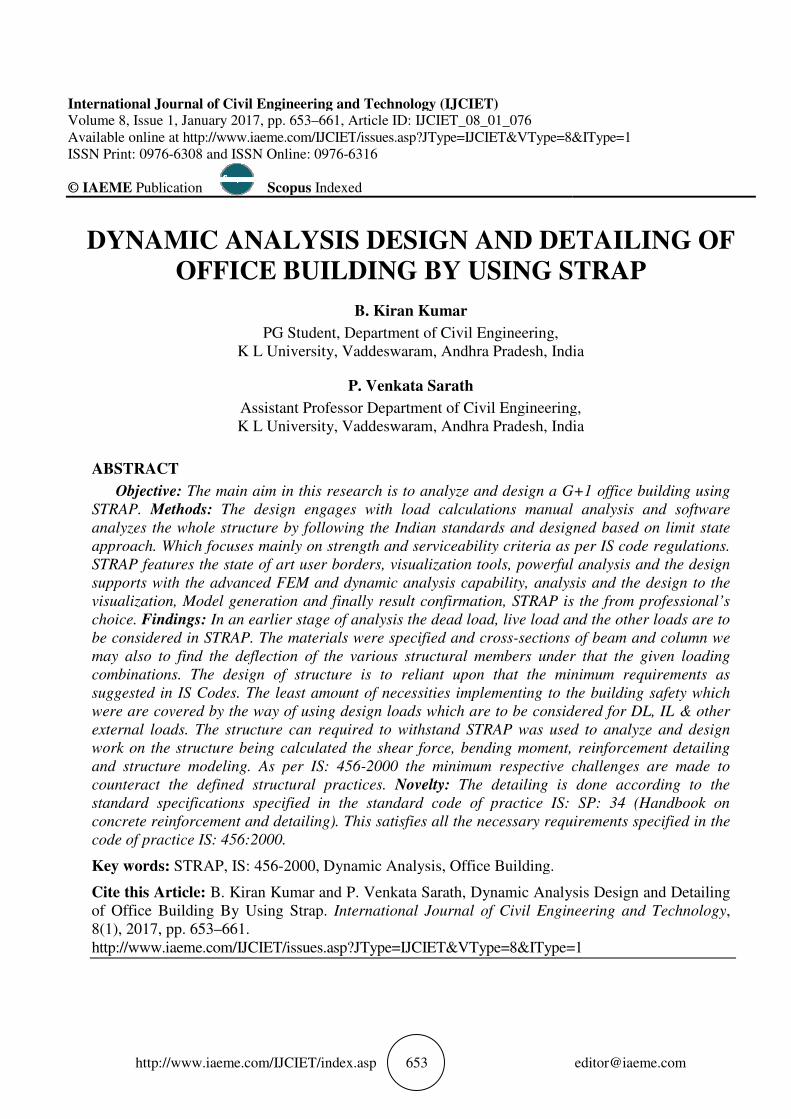
prepared ground floor plan contains a reception, working area, dining hall, manager room and washes area.
The first floor contains a conference hall, stationary room, working area, officer room and washes rooms
Design modules are essential to
sections. To focus mainly on in dynamic
Response Spectrum Analysis calculations by considering the codes and time history response
as well. The main objective to learn using STRAP is almost absent. The flowchart of the program is
to the analysis and design process performed by manually
As per the standards the setbacks for the building are taken 4 meters on the
other sides of the plot. All the External walls are kept 230mm and the walls which come inside are kept
115mm. Doors and windows are provided as per the requirement. The stair case is provided on the outside
of the building which rises up to the level of 6 meters. The stair case is provided 5 x 2.7 and each flight
width is provided 1.2m. The tread is 300 mm and rise is 150 mm
B. Kiran Kumar and P. Venkata Sarath
IJCIET/index.asp 654
The positions of the structural elements should be such that, they should not interrupt the architectural
plan. The positions of the column are selected such that they merge with walls and still be economical.
Beams should be placed beneath almost every wall depending up on the load. Extra care should be taken
while placing beams in halls. After finalizing the element positions, spans of elements are obtained.
prepared ground floor plan contains a reception, working area, dining hall, manager room and washes area.
The first floor contains a conference hall, stationary room, working area, officer room and washes rooms
Design modules are essential to execute RCC, PSC, and structural steel like hot rolled and built up
sections. To focus mainly on in dynamic effects, STRAP can also do the modal analysis and Seismic
Response Spectrum Analysis calculations by considering the codes and time history response
as well. The main objective to learn using STRAP is almost absent. The flowchart of the program is
to the analysis and design process performed by manually2.
As per the standards the setbacks for the building are taken 4 meters on the
other sides of the plot. All the External walls are kept 230mm and the walls which come inside are kept
115mm. Doors and windows are provided as per the requirement. The stair case is provided on the outside
h rises up to the level of 6 meters. The stair case is provided 5 x 2.7 and each flight
width is provided 1.2m. The tread is 300 mm and rise is 150 mm3.
Figure 1 Ground floor Plan
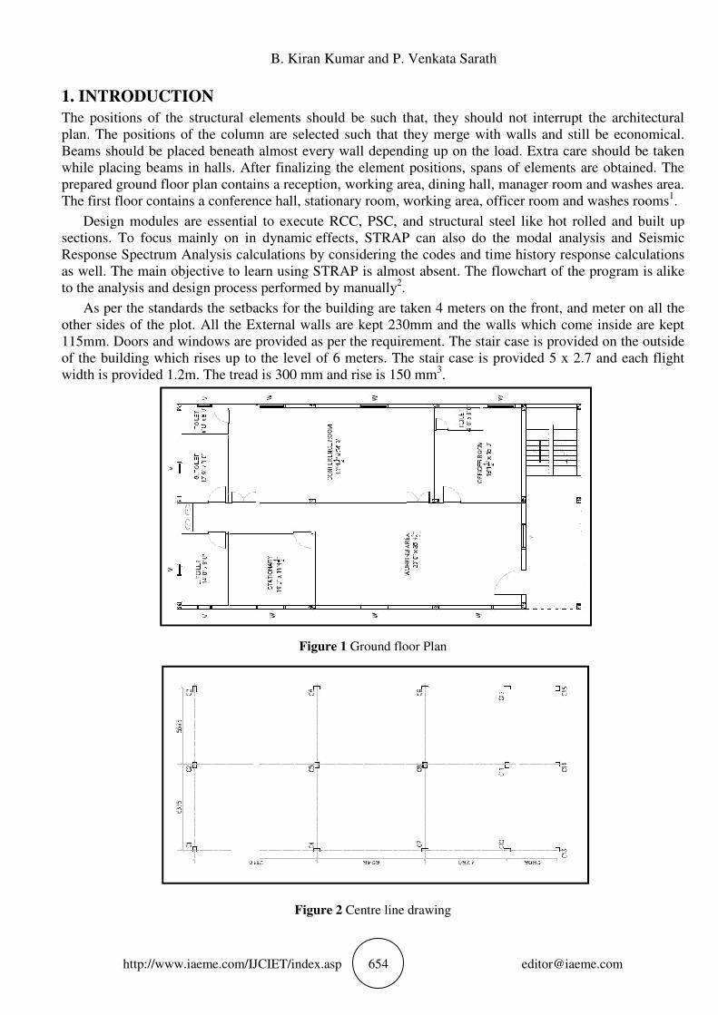
Figure 2 Centre line drawing
The positions of the structural elements should be such that, they should not interrupt the architectural
that they merge with walls and still be economical.
Beams should be placed beneath almost every wall depending up on the load. Extra care should be taken
while placing beams in halls. After finalizing the element positions, spans of elements are obtained. The
prepared ground floor plan contains a reception, working area, dining hall, manager room and washes area.
The first floor contains a conference hall, stationary room, working area, officer room and washes rooms1.
execute RCC, PSC, and structural steel like hot rolled and built up
effects, STRAP can also do the modal analysis and Seismic
Response Spectrum Analysis calculations by considering the codes and time history response calculations
as well. The main objective to learn using STRAP is almost absent. The flowchart of the program is alike
As per the standards the setbacks for the building are taken 4 meters on the front, and meter on all the
other sides of the plot. All the External walls are kept 230mm and the walls which come inside are kept
115mm. Doors and windows are provided as per the requirement. The stair case is provided on the outside
h rises up to the level of 6 meters. The stair case is provided 5 x 2.7 and each flight

Dynamic Analysis Design and Detailing of Office Building by Using Strap
http://www.iaeme.com/IJCIET/index.asp 655 [email protected]
2. METHODOLOGY
2.1. Working with Strap
Definition of the simple plane frame, using the strap’s model wizard library. strap contains a library of
standard structures that was enables the user to easily and the quickly defining the model geometry and
loads by entering a small number of parameters. The library can extended to include that the additional
models types. Utilization of “copy” feature for the defining diagonals in the upper stories. Strap’s copy
commands are powerful and sophisticated. The program refrains duplicating the existing beams. In
example, the program will duplicate only the diagonals and not the other existing members. (Beams and
columns)4.
2.2. Generation of Structure
• The structure is generated using the Graphical User Interface.
The structure is nothing but the combination of nodes and elements with specified distance with the
help of co-ordinates.
• The nodal distances are obtained from center line drawings.
The final element spans are obtained from the finalized architectural plan. Double nodes can cause
problems in the structure while running analysis. Properties of elements are changed according to the
moments obtained. Member capacities are maintained to be within the prescribed value. Reinforcement
bars minimum to maximum are specified. Grade of concrete and steel are specified to meet the
requirements of the market availability. Cover is provided to the members which may vary with the type of
member and its duties. The member parameters and the cross-section dimensions are managed to meet the
requirements5. Grouping of elements are done for minimizing the number of types of elements to minimize
the confusion in execution6.
Figure 4 Generated framed structure Figure 5 Generation of Properties

http://www.iaeme.com/IJCIET/index.
B. Kiran Kumar and P. Venkata Sarath
IJCIET/index.asp 656
Figure 6 Self Weights Applied
Figure 7 Interior wall loads Applied
Figure 8 Exterior wall loads Applied
Dynamic Analysis Design and Detailing of Office B
http://www.iaeme.com/IJCIET/index.
3. ANALYSISNG THE STRUCTURE
Solving the structure performs all the calculations and gives the behavior
combinations. The design of reinforcement is done based on that behavior. Deflections, moments, shear
force, etc are checked to be within the permissible limits.
Dynamic Analysis Design and Detailing of Office Building by Using Strap
IJCIET/index.asp 657
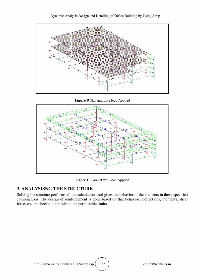
Figure 9 Slab and Live load Applied
Figure 10 Parapet wall load Applied
RUCTURE
Solving the structure performs all the calculations and gives the behavior of the elements in those specified
combinations. The design of reinforcement is done based on that behavior. Deflections, moments, shear
force, etc are checked to be within the permissible limits.
y Using Strap
of the elements in those specified
combinations. The design of reinforcement is done based on that behavior. Deflections, moments, shear

http://www.iaeme.com/IJCIET/index.
B. Kiran Kumar and P. Venkata Sarath
IJCIET/index.asp 658
Figure 11 Deflections of the elements
Figure 12 Deflections on a single floor
Figure 13 Deflections of a single frame
Dynamic Analysis Design and Detailing of Office B
http://www.iaeme.com/IJCIET/index.
4. RESULTS
After specifying the design parameters in to the program, analysis is done by doing all the necessary
calculations. An output file with reinforcement details and their posi
exceeding of allowable deflection, reinforcement, moments are eliminated and made economical. The slab
analysis details are mentioned clearly with moments in all different directions x, y, z.
Dynamic Analysis Design and Detailing of Office Building by Using Strap
IJCIET/index.asp 659
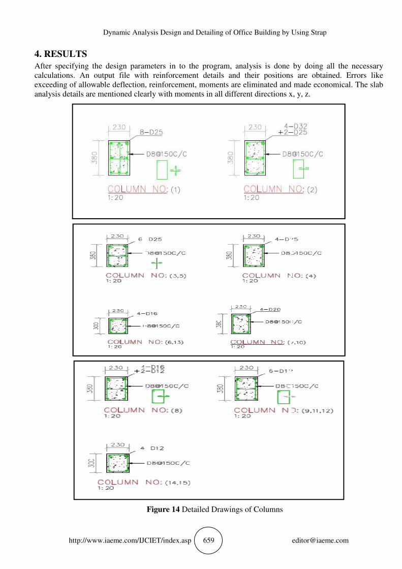
After specifying the design parameters in to the program, analysis is done by doing all the necessary
calculations. An output file with reinforcement details and their positions are obtained. Errors like
exceeding of allowable deflection, reinforcement, moments are eliminated and made economical. The slab
analysis details are mentioned clearly with moments in all different directions x, y, z.
Figure 14 Detailed Drawings of Columns
y Using Strap
After specifying the design parameters in to the program, analysis is done by doing all the necessary
tions are obtained. Errors like
exceeding of allowable deflection, reinforcement, moments are eliminated and made economical. The slab
analysis details are mentioned clearly with moments in all different directions x, y, z.
http://www.iaeme.com/IJCIET/index.
5. DETAILED DRAWINGS
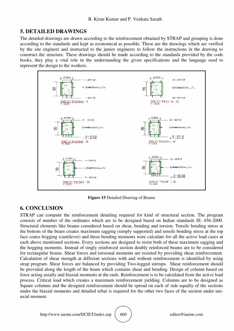
The detailed drawings are drawn according to the reinforcement obtained by STRAP and grouping is done
according to the standards and kept as economical as possible. These are the drawings which are verified
by the site engineer and instructed to the junior engineers to follow the instructions in the drawing to
construct the structure. These drawings should be made according to the standards provided by the code
books, they play a vital role in the understanding the g
represent the design to the workers.
6. CONCLUSION
STRAP can compute the reinforcement detailing required for kind of structural section. The program
consists of number of the ordinates which are to be designed based on Indian standards IS: 456
Structural elements like beams considered based on shear, bending and torsion. Tensile bending stress at
the bottom of the beam creates maximum sagging (simply supported) and ten
face crates hogging (cantilever) and these bending moments were calculate for all the active load cases at
each above mentioned sections. Every sections are designed to resist both of these maximum sagging and
the hogging moments. Instead of singly reinforced section doubly reinforced beams are to be considered
for rectangular beams. Shear forces and torsional moments are resisted by providing shear reinforcement.
Calculation of shear strength at different sections with and w
strap program. Shear forces are balanced by providing Two
be provided along the length of the beam which contains shear and bending. Design of column based on
force acting axially and biaxial moments at the ends. Reinforcement is to be calculated from the active load
process. Critical load which creates a maximum reinforcement yielding. Columns are to be designed as
Square columns and the designed reinforcement should b
under the biaxial moments and detailed rebar is required for the other two faces of the section under uni
axial moment.
B. Kiran Kumar and P. Venkata Sarath
IJCIET/index.asp 660
5. DETAILED DRAWINGS
The detailed drawings are drawn according to the reinforcement obtained by STRAP and grouping is done
according to the standards and kept as economical as possible. These are the drawings which are verified
ite engineer and instructed to the junior engineers to follow the instructions in the drawing to
construct the structure. These drawings should be made according to the standards provided by the code
books, they play a vital role in the understanding the given specifications and the language used to
represent the design to the workers.
Figure 15 Detailed Drawing of Beams
STRAP can compute the reinforcement detailing required for kind of structural section. The program
he ordinates which are to be designed based on Indian standards IS: 456
Structural elements like beams considered based on shear, bending and torsion. Tensile bending stress at
the bottom of the beam creates maximum sagging (simply supported) and tensile bending stress at the top
face crates hogging (cantilever) and these bending moments were calculate for all the active load cases at
each above mentioned sections. Every sections are designed to resist both of these maximum sagging and
ents. Instead of singly reinforced section doubly reinforced beams are to be considered
for rectangular beams. Shear forces and torsional moments are resisted by providing shear reinforcement.
Calculation of shear strength at different sections with and without reinforcement is identified by using
strap program. Shear forces are balanced by providing Two-legged stirrups. Shear reinforcement should
be provided along the length of the beam which contains shear and bending. Design of column based on
ting axially and biaxial moments at the ends. Reinforcement is to be calculated from the active load
process. Critical load which creates a maximum reinforcement yielding. Columns are to be designed as
Square columns and the designed reinforcement should be spread on each of side equally of the sections
under the biaxial moments and detailed rebar is required for the other two faces of the section under uni
The detailed drawings are drawn according to the reinforcement obtained by STRAP and grouping is done
according to the standards and kept as economical as possible. These are the drawings which are verified
ite engineer and instructed to the junior engineers to follow the instructions in the drawing to
construct the structure. These drawings should be made according to the standards provided by the code
iven specifications and the language used to
STRAP can compute the reinforcement detailing required for kind of structural section. The program
he ordinates which are to be designed based on Indian standards IS: 456-2000.
Structural elements like beams considered based on shear, bending and torsion. Tensile bending stress at
sile bending stress at the top
face crates hogging (cantilever) and these bending moments were calculate for all the active load cases at
each above mentioned sections. Every sections are designed to resist both of these maximum sagging and
ents. Instead of singly reinforced section doubly reinforced beams are to be considered
for rectangular beams. Shear forces and torsional moments are resisted by providing shear reinforcement.
ithout reinforcement is identified by using
legged stirrups. Shear reinforcement should
be provided along the length of the beam which contains shear and bending. Design of column based on
ting axially and biaxial moments at the ends. Reinforcement is to be calculated from the active load
process. Critical load which creates a maximum reinforcement yielding. Columns are to be designed as
e spread on each of side equally of the sections
under the biaxial moments and detailed rebar is required for the other two faces of the section under uni-
Dynamic Analysis Design and Detailing of Office Building by Using Strap
http://www.iaeme.com/IJCIET/index.asp 661 [email protected]
REFERENCES
[1] Maziar Izadbakhsh, Alireza Rezvani, Majid Gandomkar, Sohrab Mirsaeidi. Dynamic Analysis of PMSG
Wind Turbine under Variable Wind Speeds and Load Conditions in the Grid Connected Mode. Indian
Journal of Science and Technology. 2015 July; 8-14, 1-9.
[2] Hassoun M N, Al-Manaseer A. Structural Concrete Theory and the Design, Fifth Edition ed., New
Jersey: John Wiley & Sons, Inc., 2012.
[3] IS 875 (Part1), Dead loads, unit weights of the building material and stored material (second revision),
New Delhi 110002: Bureau of Indian Standards, 1987.
[4] IS 875 (Part2), Imposed loads (second revision), New Delhi 110002: Bureau of Indian Standards, 1987.
[5] IS 456, Plain and Reinforced Concrete Code of Practice (fourth revision), New Delhi 110002: Bureau of
Indian Standards, 2000.
[6] IS: SP: 34 Handbook on concrete reinforcement and detailing, New Delhi 110002: Bureau of Indian
Standards, 1987.
[7] Anusha Kudumula, Dr. Vaishali G Ghorpade and Dr. H. Sudarsana Rao, Seismic Performance of RC
Framed Buildings Under Linear Dynamic Analysis. International Journal of Civil Engineering and
Technology , 8(1), 2017, pp. 09–16.
[8] Pradeepa. S, Gokul Raj. D and Divya M.R, A Review on Cost Assessment of Conventional Steel
Structure and Square Tubular Sections Using Force Co-Efficient Method. International Journal of Civil
Engineering and Technology, 7(4), 2016, pp.242–245.
Related Documents