Series 3000MR Photohelic ® Differenti al Pressure Switch/ Gage Specifications — Installation and Operating Instructions Bulletin E-70 DWYER INSTRUMENTS, INC. Phone: 219/879-8000 www.dwyer-inst.com P .O. BOX 373 • MICHIGA N CITY, INDIA NA 46361, U.S .A. Fax: 219/872-9057 e-mail: in fo@ dwy er -inst. com .2O .4O .60 .80 1.0 INCHESOFWATER 1/8 FEMALENPT HIGH PRESSURECONNE CTION 1/8 FEMALENPT HIGH PRESSURECONNE CTION 2-1/61 [52.39] 2 [50.80] (4) 6-32 HOLES EQUALLY SPACED ON A 5-1/8 [130.18] B.C. 1-1/4 [31 .75] Ø4-47/64 [120.25] Ø 5 [127.00] Ø4 [101.60] FACE 5-1/2 [139.70] O.D. MOU NTINGRING 5/8 [15.88] 1/8 FEMALENPT LOW PRESSURECONNE CTION 5/8 [15.88] PANEL MAX 3/16 [4.76] 2-1/2 [63.50] ELECTRICAL CONNECTIONS CAUTION: Do not exceed specified electrical rat- ings. Permanent damage not covered by warranty will result. This unit is not designed for AC line volt- age operation. Electrical connections are made by means of the cable assembly supplied which has a multi-pin female plug installed on one end which mates with t he male connector on the rear of the gage. Wire leads on the opposite end of the assembly are connected in accordance with the drawing and chart to the right. Note: An R/C (resistor/capicitator) snubber is required when switching inductive loads such as a solenoid or contactor. specify Dwyer Instruments, Inc. part number A-600. For DC circuits, also include a 1N4005 diode. Using solid state technology, the Series 3000MR Photohelic ® switch/gage combines the functions of a precise, highly repeat- able differential pressure switch with a large easy-to-read analog pressure gage employing the durable, time-proven Magnehelic ® gage design. Switch setting is easy to adjust with large external knobs on the gage face. Gage reading is unaffected by switch operation — will indicate accurately even if power is interrupted. Solid state design now results in greatly reduced size and weight. Units can be flush mounted in 4 13 ⁄ 16 ˝ (122 mm) hole or surface mounted with hardware supplied. 3000MR models employ versa- tile ele ctromec hanical re lays with gold over silver contact s — ideal for dry circuits. All models provide both low and high limit control and include 18-inch (45 cm) cable assemblies for electrical con- nections. Gage accuracy is ±2% of full scale and switch repeatability is ±1%. Switch deadband is one pointer width — less than 1% of full scale. Compatible with air and other non-combustible, non- corrosive gases, they can be used in systems with pressures to 25 psig (1.725 bar). Optional const ruction is available for use to either 35 psig (2.42 bar) or 80 psig (5.51 bar). Accessories Mounting ring, snap ring ( 4) 6-32 x 1 1 ⁄ 4 ˝ RH machine screws 18˝ (45 cm) cabl e assembl y ( panel mounting) (2) 3 ⁄ 16 ˝ tubing to 1 ⁄ 8 ˝ NPT adapters ( 3) 6-32 x 5 ⁄ 16 ˝ RH machine screws (2) 1 ⁄ 8 ˝ NPT pipe plugs (surface mounting) SPECIFICATIONS GAGE SPECIFICATIONS Service: Air and non-combustible, compatible gases. Wetted Materials: Consult Factory. Accuracy: ±2% of full scale (3000-0 ±3% of full scale). Pressure Limit: -20˝ Hg. to 25 psig (-0.677 bar to 1.72 bar). MP option; 35 psig (2.41 bar), HP option; 80 psig (5.52 bar). T emperature Limits: 20 to 120°F. (-6.67 to 48.9°C). Process Connections: 1/8 female NPT (duplicated side and back). Size: 4˝ (101.6 mm) dial face, 5˝ (127mm) O.D. x 3-1/8˝ (79.38 mm). Weight: 1.8 Ib., (816 g). SWITCH SPECIFICATIONS 3000MR Switch Type: Each setpoint has 1 Form C relay (SPDT). Relay Contacts: (resistive load) 1 Form C rated 1.0 amp @30 VDC, 0.3 amp @110 VDC or 0.5 amp @125 VAC. Gold over clad silver - suitable for dry circuits. Electrical Connections: 18˝ (46 cm) cable assembly with 8 conductors. Optional lengths to 100´ (30.5 m). Power Requirements: 24 VDC, regulated ± 10%. Mounting Orientation: Diaphragm in vertical position. Consult factory for other position orientations. Set Point Adjustment: Adjustable knobs on face. LETTER A E C B D H J F COLOR Re d Black Brown Violet Blue Green White Orange Power Supply Lo w Set Point High Set Point + - C O M N C NO C O M N C NO

Welcome message from author
This document is posted to help you gain knowledge. Please leave a comment to let me know what you think about it! Share it to your friends and learn new things together.
Transcript

8/3/2019 Dwyer Photohelic 3000mr_iom
http://slidepdf.com/reader/full/dwyer-photohelic-3000mriom 1/2
Series 3000MR Photohelic ® Differential Pressure Switch/Gage
Specifications — Installation and Operating Instructions
Bulletin E-7
DWYER INSTRUMENTS, INC. Phone: 219/879-8000 www.dwyer-inst.com
P.O. BOX 373 • MICHIGAN CITY, INDIANA 46361, U.S.A. Fax: 219/872-9057 e-mail: [email protected]
.2O.4O .60
.80
1.0
INCHESOFWATER
1/8 FEMALENPT HIGHPRESSURECONNECTION
1/8 FEMALENPT HIGHPRESSURECONNECTION
2-1/61[52.39]
2[50.80]
(4) 6-32 HOLESEQUALLY SPACED ON A
5-1/8 [130.18] B.C.
1-1/4[31.75]
Ø4-47/64[120.25]
Ø5[127.00]
Ø4 [101.60]FACE
5-1/2 [139.70] O.D.MOUNTINGRING
5/8[15.88]
1/8 FEMALENPT LOWPRESSURECONNECTION
5/8 [15.88]PANEL MAX
3/16[4.76]
2-1/2[63.50]
ELECTRICAL CONNECTIONS
CAUTION: Do not exceed specified electrical rat-
ings. Permanent damage not covered by warrantywill result. This unit is not designed for AC line volt-age operation.
Electrical connections are made by means of the cable assemblysupplied which has a multi-pin female plug installed on one endwhich mates with the male connector on the rear of the gage. Wireleads on the opposite end of the assembly are connected inaccordance with the drawing and chart to the right.
Note: An R/C (resistor/capicitator) snubber is required wheswitching inductive loads such as a solenoid or contacto
specify Dwyer Instruments, Inc. part number A-600. For Dcircuits, also include a 1N4005 diode.
Using solid state technology, the Series 3000MR Photohelic ®
switch/gage combines the functions of a precise, highly repeat-able differential pressure switch with a large easy-to-read analog
pressure gage employing the durable, time-proven Magnehelic ®
gage design. Switch setting is easy to adjust with large externalknobs on the gage face. Gage reading is unaffected by switchoperation — will indicate accurately even if power is interrupted.Solid state design now results in greatly reduced size and weight.Units can be flush mounted in 413 ⁄ 16 ˝ (122 mm) hole or surfacemounted with hardware supplied. 3000MR models employ versa-tile electromechanical relays with gold over silver contacts — idealfor dry circuits. All models provide both low and high limit controland include 18-inch (45 cm) cable assemblies for electrical con-nections.
Gage accuracy is ±2% of full scale and switch repeatability is±1%. Switch deadband is one pointer width — less than 1% offull scale. Compatible with air and other non-combustible, non-corrosive gases, they can be used in systems with pressures to25 psig (1.725 bar). Optional const ruction is available for use toeither 35 psig (2.42 bar) or 80 psig (5.51 bar).
AccessoriesMounting ring, snap ring (4) 6-32 x 11 ⁄ 4 ̋RH machine screws18˝ (45 cm) cable assembly (panel mounting)(2) 3 ⁄ 16 ˝ tubing to 1 ⁄ 8 ̋ NPT adapters (3) 6-32 x 5 ⁄ 16 ̋RH machine screws(2) 1 ⁄ 8 ˝ NPT pipe plugs (surface mounting)
SPECIFICATIONSGAGE SPECIFICATIONSService: Air and non-combustible, compatible gases.Wetted Materials: Consult Factory.
Accuracy: ±2% of full scale (3000-0 ±3% of full scale).Pressure Limit: -20˝ Hg. to 25 psig (-0.677 bar to 1.72 bar). MP optio35 psig (2.41 bar), HP option; 80 psig (5.52 bar).Temperature Limits: 20 to 120°F. (-6.67 to 48.9°C).Process Connections: 1/8 female NPT (duplicated side and back).Size: 4˝ (101.6 mm) dial face, 5˝ (127mm) O.D. x 3-1/8˝ (79.38 mm).Weight: 1.8 Ib., (816 g).
SWITCH SPECIFICATIONS 3000MRSwitch Type: Each setpoint has 1 Form C relay (SPDT).Relay Contacts: (resistive load) 1 Form C rated 1.0 amp @30 VDC, 0amp @110 VDC or 0.5 amp @125 VAC. Gold over clad silver - suitabfor dry circuits.Electrical Connections: 18˝ (46 cm) cable assembly with 8 conductoOptional lengths to 100´ (30.5 m).Power Requirements: 24 VDC, regulated ± 10%.Mounting Orientation: Diaphragm in vertical position. Consult factoryother position orientations.Set Point Adjustment: Adjustable knobs on face.
LETTER
AECBDHJF
COLOR
RedBlackBrownVioletBlue
GreenWhite
Orange
PowerSupply
LowSet Point
HighSet Point
+-
COMNCNO
COMNCNO
8/3/2019 Dwyer Photohelic 3000mr_iom
http://slidepdf.com/reader/full/dwyer-photohelic-3000mriom 2/2
DWYER INSTRUMENTS, INC. Phone: 219/879-8000 www.dwyer-inst.com
P.O. BOX 373 • MICHIGAN CITY, INDIANA 46361, U.S.A. Fax: 219/872-9057 e-mail: [email protected]
INSTALLATION
1. LOCATION: Select a location where the temperature of theunit will be between 20°F and 120°F (-6.67 to 48.9°C). Thetubing feeding pressure to the instrument can be run prac-tically any length required but long lengths will increaseresponse time slightly. Avoid surfaces with excessive vibra-tion.
2. POSITION: All standard models are calibrated with thediaphragm vertical and should be used in that position for
maximum accuracy. If your application requires mounting inother than a vertical position, be sure to specify this whenordering.
3. PRESSURE CONNECTIONS: For convenience, two setsof 1/8˝ female NPT ports are available. Plug the unused setwith pipe plugs provided. Attach tubing from positive pres-sure source to port marked “HI” or from negative (Vacuum)source to port marked “LOW”. In either case, opposite portmust be vented to atmosphere. In dusty environments, werecommend use of an A-331 Filter Vent Plug to keep interi-or of instrument clean. For differential pressures the highersource is connected to the “HI” port and lower to the “LOW”port.
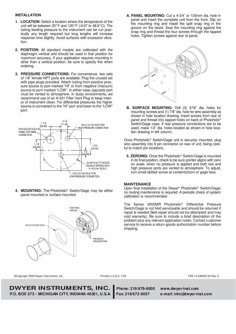
4. MOUNTING: The Photohelic ® Switch/Gage may be eitherpanel mounted or surface mounted.
A. PANEL MOUNTING: Cut a 4-3/4˝ or 120mm dia. hole panel and insert the complete unit from the front. Slip othe mounting ring and install the split snap ring in thgroove on the bezel. Seat the mounting ring against thsnap ring and thread the four screws through the tappeholes. Tighten screws against rear of panel.
B. SURFACE MOUNTING: Drill (3) 3/16˝ dia. holes fmounting screws and (1) 7/8˝ dia. hole for wire assembly a
shown in hole location drawing. Insert screws from rear panel and thread into tapped holes on back of PhotohelicSwitch/Gage case. If rear pressure connections are to bused, make 1/2˝ dia. holes located as shown in hole location drawing in left column.
Once Photohelic ® Switch/Gage unit is securely mounted, pluwire assembly into 9 pin connector on rear of unit, being careful to match pin locations.
5. ZEROING: Once the Photohelic ® Switch/Gage is mountein its final position, check to be sure pointer aligns with zeron scale, when no pressure is applied and both low anhigh pressure ports are vented to atmosphere. To adjusturn small slotted screw at center-bottom of gage face.
MAINTENANCEUpon final installation of the Dwyer ® Photohelic ® Switch/Gagno routing maintenance is required. A periodic check of systemcalibration is recommended.
The Series 3000MR Photohelic ® Differential PressuSwitch/Gage is not field serviceable and should be returned repair is needed (field repair should not be attempted and mavoid warranty). Be sure to include a brief description of thproblem plus any relevant application notes. Contact customeservice to receive a return goods authorization number beforshipping.
©Copyright 2009 Dwyer Instruments, Inc. Printed in U.S.A. 7/09 FR# 13-440622-00 Rev. 5
Ø4-3/4 [120.65] HOLE
SNAP RINGGROOVE
PNEUMATICPRESSURETAPS
Ø7/8 [22.23] HOLE INPANEL FOR WIRECONNECTION
1-1/8[28.58]
1-1/8[28.58]
11/16[17.46] Ø1/2 [12.70] HOLE FOR
HIGH PRESSURE CONNECTION
1-3/4[44.45]
1/2[12.70]
(3) Ø3/16 [4.77] HOLESEQUALLY SPACED ON A
4-1/8 [104.78] B.C.
Ø1/2 [12.70] HOLE FOR
LOW PRESSURE CONNECTION
Related Documents