ROBO CYLINDER® RCP4W series www.intelligentactuator.com Dust-proof/Splash-proof

Welcome message from author
This document is posted to help you gain knowledge. Please leave a comment to let me know what you think about it! Share it to your friends and learn new things together.
Transcript
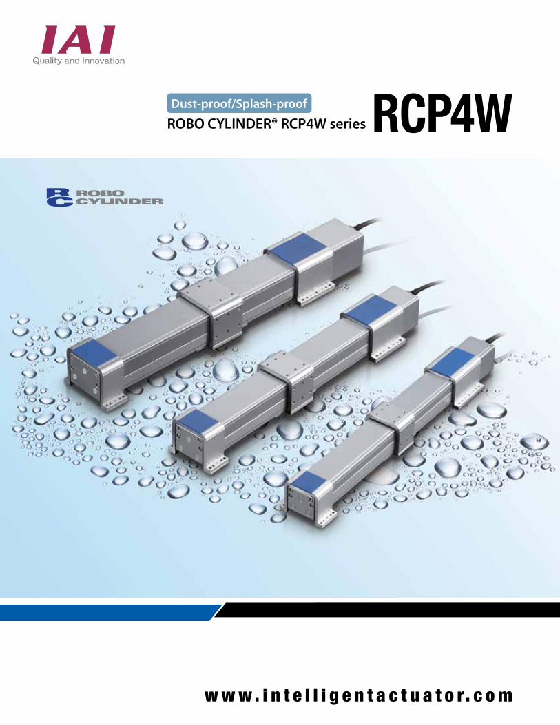
ROBO CYLINDER® RCP4W series
www. i n t e l l i g e n t a c t u a t o r. c om
Dust-proof/Splash-proof
1
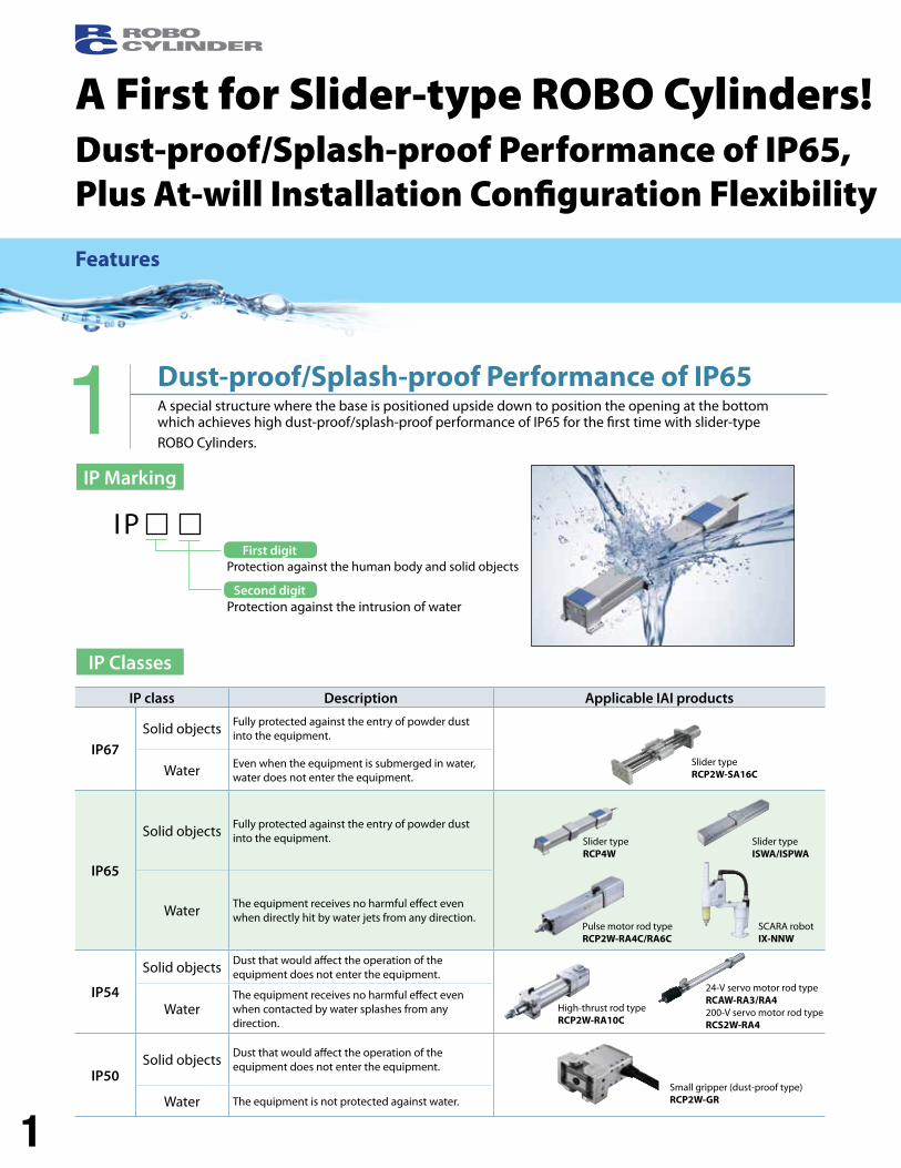
1 Dust-proof/Splash-proof Performance of IP65A special structure where the base is positioned upside down to position the opening at the bottom which achieves high dust-proof/splash-proof performance of IP65 for the first time with slider-type ROBO Cylinders.
A First for Slider-type ROBO Cylinders!Dust-proof/Splash-proof Performance of IP65, Plus At-will Installation Configuration Flexibility
First digit
Features
IP Marking
IP Classes
Protection against the human body and solid objects
Protection against the intrusion of water
IP
IP class Description Applicable IAI products
IP67Solid objects Fully protected against the entry of powder dust
into the equipment.
Water Even when the equipment is submerged in water, water does not enter the equipment.
IP65
Solid objects Fully protected against the entry of powder dust into the equipment.
Water The equipment receives no harmful effect even when directly hit by water jets from any direction.
IP54
Solid objects Dust that would affect the operation of theequipment does not enter the equipment.
WaterThe equipment receives no harmful effect even when contacted by water splashes from any direction.
IP50Solid objects Dust that would affect the operation of the
equipment does not enter the equipment.
Water The equipment is not protected against water.
Slider typeRCP2W-SA16C
Slider typeRCP4W
Slider type ISWA/ISPWA
Pulse motor rod typeRCP2W-RA4C/RA6C
SCARA robotIX-NNW
High-thrust rod typeRCP2W-RA10C
24-V servo motor rod typeRCAW-RA3/RA4200-V servo motor rod typeRCS2W-RA4
Small gripper (dust-proof type)RCP2W-GR
First digit
Second digit
2
RCP4W
3
45
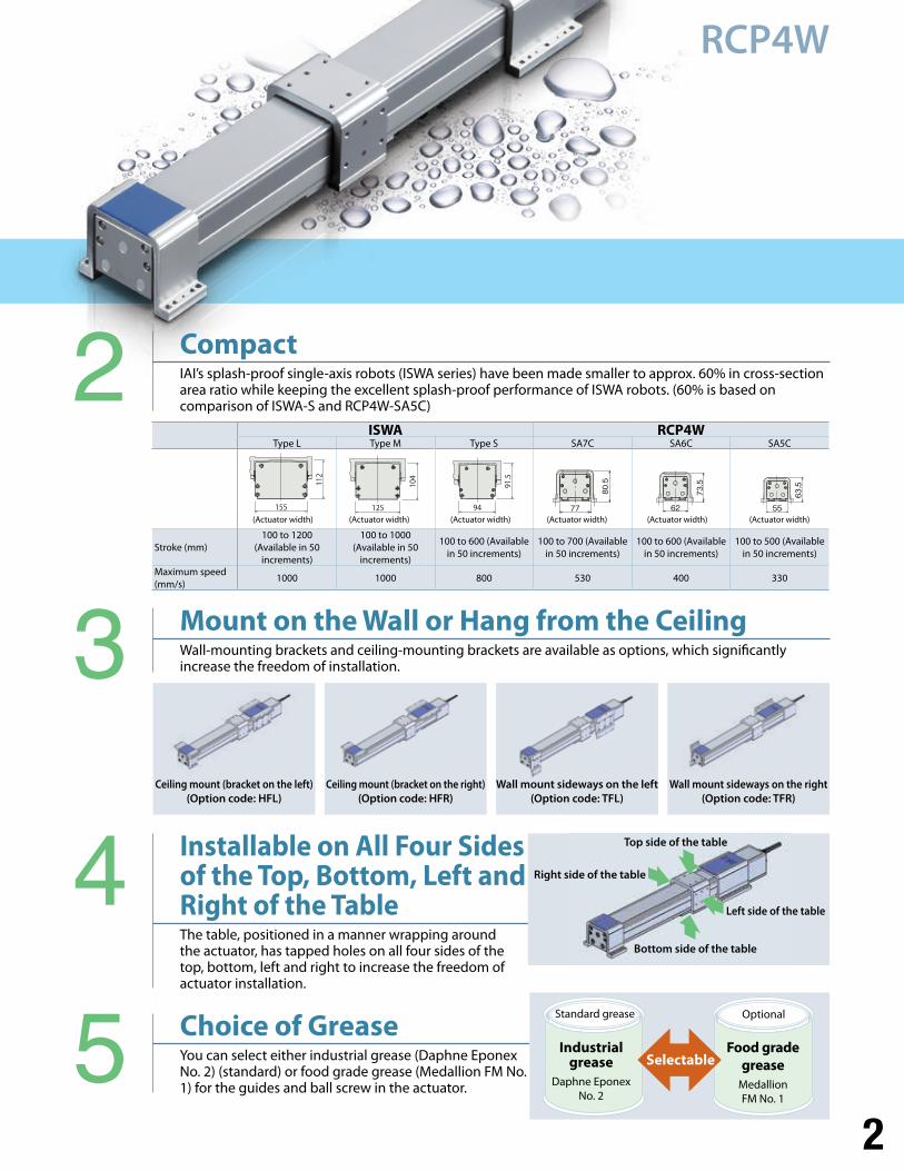
Mount on the Wall or Hang from the Ceiling Wall-mounting brackets and ceiling-mounting brackets are available as options, which significantly increase the freedom of installation.
Installable on All Four Sides of the Top, Bottom, Left and Right of the TableThe table, positioned in a manner wrapping around the actuator, has tapped holes on all four sides of the top, bottom, left and right to increase the freedom of actuator installation.
Choice of Grease You can select either industrial grease (Daphne Eponex No. 2) (standard) or food grade grease (Medallion FM No. 1) for the guides and ball screw in the actuator.
2 CompactIAI’s splash-proof single-axis robots (ISWA series) have been made smaller to approx. 60% in cross-section area ratio while keeping the excellent splash-proof performance of ISWA robots. (60% is based on comparison of ISWA-S and RCP4W-SA5C)
ISWA RCP4WType L Type M Type S SA7C SA6C SA5C
w
Stroke (mm)100 to 1200
(Available in 50 increments)
100 to 1000 (Available in 50
increments)
100 to 600 (Available in 50 increments)
100 to 700 (Available in 50 increments)
100 to 600 (Available in 50 increments)
100 to 500 (Available in 50 increments)
Maximum speed (mm/s)
1000 1000 800 530 400 330
(Actuator width) (Actuator width) (Actuator width) (Actuator width) (Actuator width) (Actuator width)
Ceiling mount (bracket on the left) (Option code: HFL)
Wall mount sideways on the left (Option code: TFL)
Ceiling mount (bracket on the right) (Option code: HFR)
Wall mount sideways on the right(Option code: TFR)
Right side of the table
Top side of the table
Standard grease
Industrial grease
Daphne Eponex No. 2
Food grade grease
Medallion FM No. 1
Optional
Selectable
Left side of the table
Bottom side of the table
3
Specification List
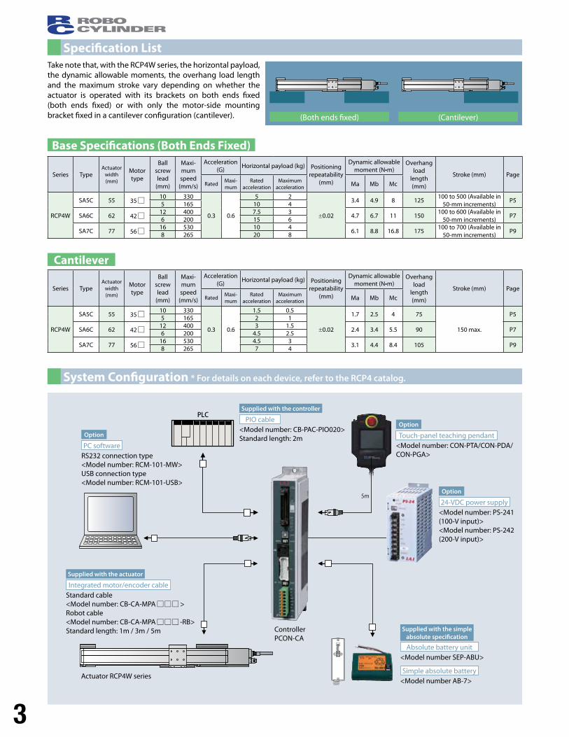
System Configuration * For details on each device, refer to the RCP4 catalog.
PLC
5m
Take note that, with the RCP4W series, the horizontal payload, the dynamic allowable moments, the overhang load length and the maximum stroke vary depending on whether the actuator is operated with its brackets on both ends fixed (both ends fixed) or with only the motor-side mounting bracket fixed in a cantilever configuration (cantilever).
Base Specifications (Both Ends Fixed)
Cantilever
Series TypeActuator
width (mm)
Motor type
Ball screw lead
(mm)
Maxi-mum speed
(mm/s)
Acceleration (G)
Horizontal payload (kg) Positioning repeatability
(mm)
Dynamic allowable moment (N•m)
Overhang load
length (mm)
Stroke (mm) PageRated
Maxi-mum
Rated acceleration
Maximum acceleration Ma Mb Mc
RCP4W
SA5C 55 35 10 330
0.3 0.6
5 2
±0.02
3.4 4.9 8 125100 to 500 (Available in
50-mm increments) P5
5 165 10 4
SA6C 62 42 12 400 7.5 3
4.7 6.7 11 150100 to 600 (Available in
50-mm increments)P7
6 200 15 6
SA7C 77 56 16 530 10 4
6.1 8.8 16.8 175100 to 700 (Available in
50-mm increments)P9
8 265 20 8
Series TypeActuator
width (mm)
Motor type
Ball screw lead
(mm)
Maxi-mum speed
(mm/s)
Acceleration (G)
Horizontal payload (kg) Positioning repeatability
(mm)
Dynamic allowable moment (N•m)
Overhang load
length (mm)
Stroke (mm) PageRated
Maxi-mum
Rated acceleration
Maximum acceleration Ma Mb Mc
RCP4W
SA5C 55 35 10 330
0.3 0.6
1.5 0.5
±0.02
1.7 2.5 4 75
150 max.
P55 165 2 1
SA6C 62 42 12 400 3 1.5
2.4 3.4 5.5 90 P76 200 4.5 2.5
SA7C 77 56 16 530 4.5 3
3.1 4.4 8.4 105 P98 265 7 4
(Both ends fixed) (Cantilever)
Option
Option
Option
Supplied with the actuator
Supplied with the controller
Supplied with the simple absolute specification
PC software
24-VDC power supply
Touch-panel teaching pendant
Integrated motor/encoder cable
PIO cable
Absolute battery unit
Simple absolute battery
RS232 connection type <Model number: RCM-101-MW>USB connection type <Model number: RCM-101-USB>
<Model number: PS-241 (100-V input)><Model number: PS-242 (200-V input)>
<Model number: CON-PTA/CON-PDA/CON-PGA>
Standard cable<Model number: CB-CA-MPA >Robot cable<Model number: CB-CA-MPA -RB>Standard length: 1m / 3m / 5m
<Model number: CB-PAC-PIO020>Standard length: 2m
<Model number SEP-ABU>
<Model number AB-7>Actuator RCP4W series
Controller PCON-CA
4
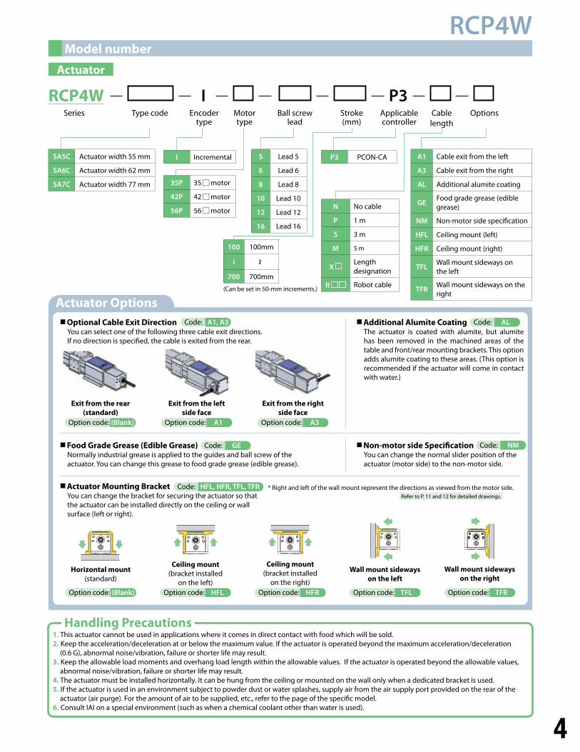
RCP4WModel number
Actuator
RCP4W I P3 Ball screw
leadStroke (mm)
Motor type
Series Type code Applicable controller
OptionsCable length
Encoder type
SA5C Actuator width 55 mm
SA6C Actuator width 62 mm
SA7C Actuator width 77 mm
N No cable
P 1 m
S 3 m
M 5 m
X Length designation
R Robot cable
A1 Cable exit from the left
A3 Cable exit from the right
AL Additional alumite coating
GEFood grade grease (edible grease)
NM Non-motor side specification
HFL Ceiling mount (left)
HFR Ceiling mount (right)
TFLWall mount sideways on the left
TFRWall mount sideways on the right
35P 35 motor
42P 42 motor
56P 56 motor
5 Lead 5
6 Lead 6
8 Lead 8
10 Lead 10
12 Lead 12
16 Lead 16
I Incremental P3 PCON-CA
Handling Precautions 1. This actuator cannot be used in applications where it comes in direct contact with food which will be sold. 2. Keep the acceleration/deceleration at or below the maximum value. If the actuator is operated beyond the maximum acceleration/deceleration
(0.6 G), abnormal noise/vibration, failure or shorter life may result. 3. Keep the allowable load moments and overhang load length within the allowable values. If the actuator is operated beyond the allowable values,
abnormal noise/vibration, failure or shorter life may result.4. The actuator must be installed horizontally. It can be hung from the ceiling or mounted on the wall only when a dedicated bracket is used. 5. If the actuator is used in an environment subject to powder dust or water splashes, supply air from the air supply port provided on the rear of the
actuator (air purge). For the amount of air to be supplied, etc., refer to the page of the specific model. 6. Consult IAI on a special environment (such as when a chemical coolant other than water is used).
Actuator Options
Actuator Mounting Bracket You can change the bracket for securing the actuator so that the actuator can be installed directly on the ceiling or wall surface (left or right).
Optional Cable Exit Direction You can select one of the following three cable exit directions. If no direction is specified, the cable is exited from the rear.
Code: A1, A3
Food Grade Grease (Edible Grease) Normally industrial grease is applied to the guides and ball screw of the actuator. You can change this grease to food grade grease (edible grease).
Code: GE
Code: HFL, HFR, TFL, TFR
Additional Alumite Coating The actuator is coated with alumite, but alumite has been removed in the machined areas of the table and front/rear mounting brackets. This option adds alumite coating to these areas. (This option is recommended if the actuator will come in contact with water.)
Code: AL
Non-motor side Specification You can change the normal slider position of the actuator (motor side) to the non-motor side.
Code: NM
* Right and left of the wall mount represent the directions as viewed from the motor side. Refer to P. 11 and 12 for detailed drawings.
Option code: A3
Exit from the right side face
Option code: A1
Exit from the left side face
Option code: (Blank)
Exit from the rear (standard)
Option code: (Blank)
Horizontal mount (standard)
Option code: HFL
Ceiling mount (bracket installed
on the left) Option code: HFR
Ceiling mount (bracket installed
on the right) Option code: TFL
Wall mount sideways on the left
Option code: TFR
Wall mount sideways on the right
100 100mm
700 700mm
(Can be set in 50-mm increments.)
~ ~
5
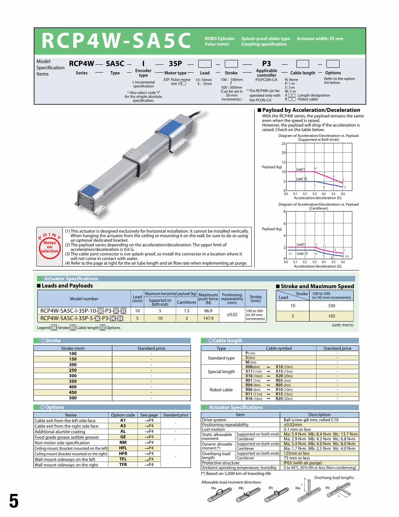
RCP4W-SA5C
Payload by Acceleration/Deceleration With the RCP4W series, the payload remains the same even when the speed is raised. However, the payload will drop if the acceleration is raised. Check on the table below.
Options Actuator Specifications
(unit: mm/s)
Actuator Specifications Leads and Payloads Stroke and Maximum Speed
L
L
Ma MaMb Mc Mc
Allowable load moment directions Overhang load lengths
Model number Lead(mm)
Maximum horizontal payload (kg) Maximum push force
(N)
Positioning repeatability
(mm)Stroke (mm)Supported on
both ends Cantilever
RCP4W-SA5C-I-35P-10- 1 -P3- 2 - 3 10 5 1.5 66.9±0.02
100 to 500(in 50-mm increments)RCP4W-SA5C-I-35P-5- 1 -P3- 2 - 3 5 10 2 147.9
Stroke (mm) Standard price100 -150 -200 -250 -300 -350 -400 -450 -500 -
Item DescriptionDrive system Ball screw φ8 mm, rolled C10Positioning repeatability ±0.02mmLost motion 0.1 mm or lessStatic allowable moment
Supported on both ends Ma: 5.9 N•m Mb: 8.4 N•m Mc: 13.7 N•mCantilever Ma: 2.9 N•m Mb: 4.2 N•m Mc: 6.8 N•m
Dynamic allowable moment (*)
Supported on both ends Ma: 3.4 N•m Mb: 4.9 N•m Mc: 8.0 N•mCantilever Ma: 1.7 N•m Mb: 2.5 N•m Mc: 4.0 N•m
Overhang load length
Supported on both ends 125mm or lessCantilever 75 mm or less
Protective structure IP65 (with air purge) Ambient operating temperature, humidity 0 to 40°C, 85% RH or less (Non-condensing)
Name Option code See page Standard priceCable exit from the left side face A1 P4
-Cable exit from the right side face A3 P4Additional alumite coating AL P4 -Food grade grease (edible grease) GE P4
-Non-motor side specification NM P4Ceiling mount (bracket mounted on the left) HFL P4
-Ceiling mount (bracket mounted on the right) HFR P4Wall mount sideways on the left TFL P4Wall mount sideways on the right TFR P4
(*) Based on 5,000 km of traveling life
Noteson
selection
(1) This actuator is designed exclusively for horizontal installation. It cannot be installed vertically. When hanging the actuator from the ceiling or mounting it on the wall, be sure to do so using an optional dedicated bracket.
(2) The payload varies depending on the acceleration/deceleration. The upper limit of acceleration/deceleration is 0.6 G.
(3) The cable joint connector is not splash-proof, so install the connector in a location where it will not come in contact with water.
(4) Refer to the page at right for the air tube length and air flow rate when implementing air purge.
100 to 500(in 50-mm increments)
10 330
5 165
35P: Pulse motor size 35I: Incremental
specification
P3:PCON-CA Refer to the option list below.
100 : 100mm
500 : 500mm(Can be set in
50-mm increments.)
* Also select code “I” for the simple absolute
specification.
10 : 10mm5 : 5mm
SA5CType
IEncoder
type
35PMotor type
P3Applicable controllerLead Stroke Cable length Options
RCP4WSeries
8
6
4
2
00.60.50.40.30.20.10.0
25
15
20
10
5
00.60.50.40.30.20.10.0
44
44
6688
1010
5533 22
11
11
1.21.2
0.50.50.70.7
1.51.5
1.51.51.51.5
22
Lead 5
Lead 10
Lead 5
Lead 10
Lead 5
Lead 10
Lead 5
Lead 10
* The RCP4W can be operated only with the PCON-CA
Model Specification Items
~ N: NoneP: 1 mS: 3 mM: 5 mX : Length designationR : Robot cable
Diagram of Acceleration/Deceleration vs. Payload [Supported at Both Ends]
Payload (kg)
Payload (kg)
Acceleration/deceleration (G)
Acceleration/deceleration (G)
Diagram of Acceleration/Deceleration vs. Payload [Cantilever]
Legend 1 Stroke 2 Cable length 3 Options
StrokeLead
Type Cable symbol Standard price
Standard typeP (1m) -S (3m) -M (5m) -
Special lengthX06 (6m) X10 (10m) -X11 (11m) X15 (15m) -X16 (16m) X20 (20m) -
Robot cable
R01 (1m) R03 (3m) -R04 (4m) R05 (5m) -R06 (6m) R10 (10m) -R11 (11m) R15 (15m) -R16 (16m) R20 (20m) -
~
~
~
~
~
~
~
~
Stroke1
3
Cable length2
ROBO Cylinder Splash-proof slider type Actuator width: 55 mm Pulse motor Coupling specification
6
5 5STROKE10 50 29 9045
A 61L
257.5357.5
ME SE
7.5357.5 303022.5
55
55
5102010545
105070
BCD
22.52012.5355
75
22.5
41
5
85
7.5
25
20
25
(2m)
(17)
(17)
55 70
CAD drawings can be downloaded from the website. www.intelligentactuator.com
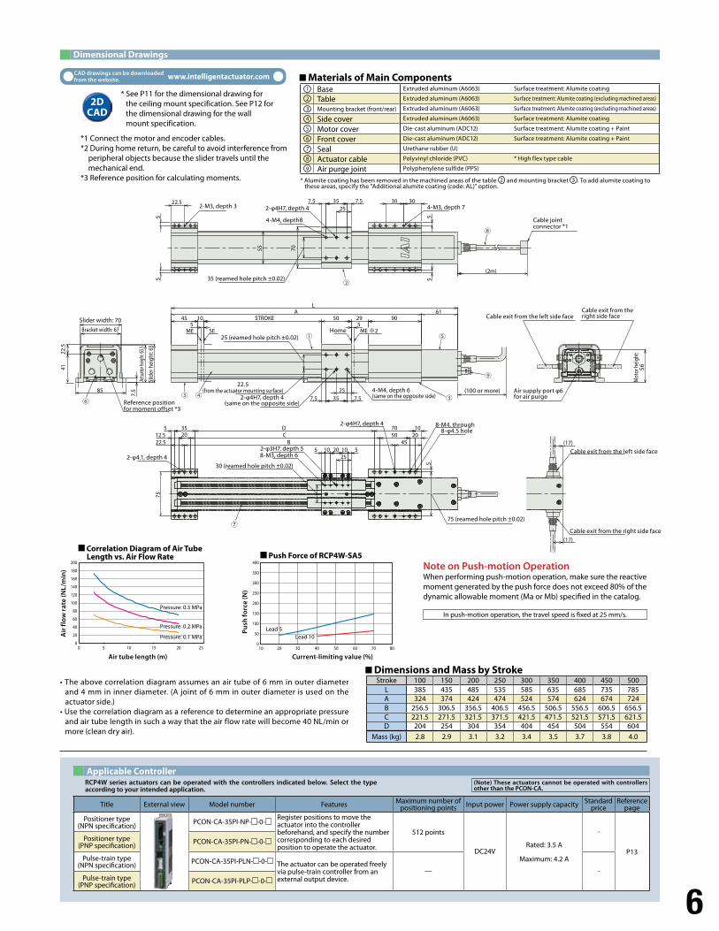
Dimensional Drawings
Applicable Controller
Dimensions and Mass by Stroke
RCP4W series actuators can be operated with the controllers indicated below. Select the type according to your intended application.
Title External view Model number Features Maximum number of positioning points Input power Power supply capacity Standard
priceReference
page
Positioner type(NPN specification) PCON-CA-35PI-NP- -0-
Register positions to move the actuator into the controller beforehand, and specify the number corresponding to each desired position to operate the actuator.
512 points
DC24VRated: 3.5 A
Maximum: 4.2 A
-
P13
Positioner type(PNP specification) PCON-CA-35PI-PN- -0-
Pulse-train type(NPN specification) PCON-CA-35PI-PLN- -0- The actuator can be operated freely
via pulse-train controller from an external output device.
— -Pulse-train type
(PNP specification) PCON-CA-35PI-PLP- -0-
Stroke 100 150 200 250 300 350 400 450 500L 385 435 485 535 585 635 685 735 785A 324 374 424 474 524 574 624 674 724B 256.5 306.5 356.5 406.5 456.5 506.5 556.5 606.5 656.5C 221.5 271.5 321.5 371.5 421.5 471.5 521.5 571.5 621.5D 204 254 304 354 404 454 504 554 604
Mass (kg) 2.8 2.9 3.1 3.2 3.4 3.5 3.7 3.8 4.0
* See P11 for the dimensional drawing for the ceiling mount specification. See P12 for the dimensional drawing for the wall mount specification.
*1 Connect the motor and encoder cables.*2 During home return, be careful to avoid interference from
peripheral objects because the slider travels until the mechanical end.
*3 Reference position for calculating moments.
2DCAD
• The above correlation diagram assumes an air tube of 6 mm in outer diameter and 4 mm in inner diameter. (A joint of 6 mm in outer diameter is used on the actuator side.)
• Use the correlation diagram as a reference to determine an appropriate pressure and air tube length in such a way that the air flow rate will become 40 NL/min or more (clean dry air).
Note on Push-motion Operation When performing push-motion operation, make sure the reactive moment generated by the push force does not exceed 80% of the dynamic allowable moment (Ma or Mb) specified in the catalog.
In push-motion operation, the travel speed is fixed at 25 mm/s.
Materials of Main Components Base Extruded aluminum (A6063) Surface treatment: Alumite coating
Table Extruded aluminum (A6063) Surface treatment: Alumite coating (excluding machined areas)
Mounting bracket (front/rear) Extruded aluminum (A6063) Surface treatment: Alumite coating (excluding machined areas)
Side cover Extruded aluminum (A6063) Surface treatment: Alumite coating
Motor cover Die-cast aluminum (ADC12) Surface treatment: Alumite coating + Paint
Front cover Die-cast aluminum (ADC12) Surface treatment: Alumite coating + Paint
Seal Urethane rubber (U)
Actuator cable Polyvinyl chloride (PVC) * High flex type cable
Air purge joint Polyphenylene sulfide (PPS)
200
180
160
140
120
100
80
60
40
20
050 10 15 20 25
400
350
300
250
200
150
100
50
010 20 30 40 50 60 70 80
* Alumite coating has been removed in the machined areas of the table 2 and mounting bracket 3 . To add alumite coating to these areas, specify the "Additional alumite coating (code: AL)" option.
(Note) These actuators cannot be operated with controllers other than the PCON-CA.
1
6
2
7
3
8
4
9
5
Correlation Diagram of Air Tube Length vs. Air Flow Rate Push Force of RCP4W-SA5
Air tube length (m) Current-limiting value (%)
Air
flo
w r
ate
(NL/
min
)
Pu
sh fo
rce
(N)
Pressure: 0.3 MPa
Pressure: 0.2 MPaPressure: 0.2 MPa
Pressure: 0.1 MPaPressure: 0.1 MPaLead 5 Lead 5
Lead 10Lead 10
2-M3, depth 3 2-φ4H7, depth 4
4-M4, depth8
35 (reamed hole pitch ±0.02)
25 (reamed hole pitch ±0.02)
22.5 (from the actuator mounting surface)
2-φ4H7, depth 4(same on the opposite side)
4-M4, depth 6(same on the opposite side)
4-M3, depth 7
Cable joint connector *1
Slider width: 70
Bracket width: 67
Actu
ator h
eight
: 63.5
Slid
er h
eigh
t: 65
Reference position for moment offset *3
Home
(100 or more)
Cable exit from the left side face
Cable exit from the left side face
Cable exit from the right side face
Cable exit from the right side face
Air supply port φ6 for air purge
Mot
or h
eigh
t:56
2-φ4.1, depth 430 (reamed hole pitch ±0.02)
2-φ3H7, depth 58-M3, depth 6
2-φ4H7, depth 4 8-M4, through8-φ4.5 hole
75 (reamed hole pitch ±0.02)
7
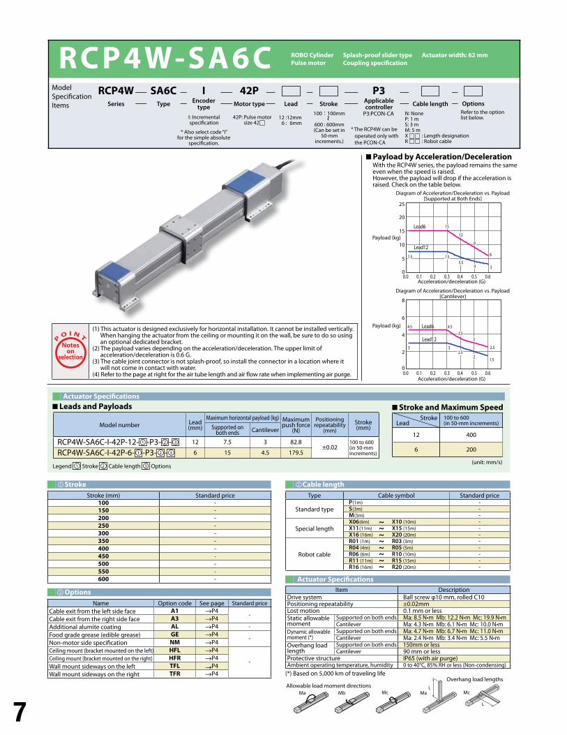
RCP4W-SA6C
Payload by Acceleration/Deceleration With the RCP4W series, the payload remains the same even when the speed is raised. However, the payload will drop if the acceleration is raised. Check on the table below.
Options
Actuator Specifications
(unit: mm/s)
Actuator Specifications Leads and Payloads Stroke and Maximum Speed
L
L
Ma MaMb Mc McAllowable load moment directions
Overhang load lengths
Model number Lead(mm)
Maximum horizontal payload (kg) Maximum push force
(N)
Positioning repeatability
(mm)Stroke (mm)Supported on
both ends Cantilever
RCP4W-SA6C-I-42P-12- 1 -P3- 2 - 3 12 7.5 3 82.8±0.02
100 to 600(in 50-mm increments)RCP4W-SA6C-I-42P-6- 1 -P3- 2 - 3 6 15 4.5 179.5
Stroke (mm) Standard price100 -150 -200 -250 -300 -350 -400 -450 -500 -550 -600 -
Item DescriptionDrive system Ball screw φ10 mm, rolled C10Positioning repeatability ±0.02mmLost motion 0.1 mm or lessStatic allowable moment
Supported on both ends Ma: 8.5 N•m Mb: 12.2 N•m Mc: 19.9 N•mCantilever Ma: 4.3 N•m Mb: 6.1 N•m Mc: 10.0 N•m
Dynamic allowable moment (*)
Supported on both ends Ma: 4.7 N•m Mb: 6.7 N•m Mc: 11.0 N•mCantilever Ma: 2.4 N•m Mb: 3.4 N•m Mc: 5.5 N•m
Overhang load length
Supported on both ends 150mm or lessCantilever 90 mm or less
Protective structure IP65 (with air purge) Ambient operating temperature, humidity 0 to 40°C, 85% RH or less (Non-condensing)
Name Option code See page Standard priceCable exit from the left side face A1 P4
-Cable exit from the right side face A3 P4Additional alumite coating AL P4 -Food grade grease (edible grease) GE P4
-Non-motor side specification NM P4Ceiling mount (bracket mounted on the left) HFL P4
-Ceiling mount (bracket mounted on the right) HFR P4Wall mount sideways on the left TFL P4Wall mount sideways on the right TFR P4 (*) Based on 5,000 km of traveling life
Noteson
selection
(1) This actuator is designed exclusively for horizontal installation. It cannot be installed vertically. When hanging the actuator from the ceiling or mounting it on the wall, be sure to do so using an optional dedicated bracket.
(2) The payload varies depending on the acceleration/deceleration. The upper limit of acceleration/deceleration is 0.6 G.
(3) The cable joint connector is not splash-proof, so install the connector in a location where it will not come in contact with water.
(4) Refer to the page at right for the air tube length and air flow rate when implementing air purge.
100 to 600(in 50-mm increments)
12 400
6 200
I: Incremental specification
P3:PCON-CA Refer to the option list below.
100 : 100mm
600 : 600mm(Can be set in
50-mm increments.)
* Also select code “I” for the simple absolute
specification.
SA6CType
IEncoder
type
42PMotor type
P3Applicable controllerLead Stroke Cable length Options
RCP4WSeries
8
6
4
2
0
25
15
20
10
5
0
0.60.50.40.30.20.10.0
0.60.50.40.30.20.10.0
1515
1212
99
667.57.57.57.55.55.5
44 33
3.53.5
2.52.52.52.5
1.51.522
33
33
4.54.5
33
4.54.5
Lead6Lead6
Lead6Lead12
Lead6Lead6
Lead12Lead12
* The RCP4W can be operated only with the PCON-CA
Model Specification Items
~ N: NoneP: 1 mS: 3 mM: 5 mX : Length designationR : Robot cable
Diagram of Acceleration/Deceleration vs. Payload [Supported at Both Ends]
Payload (kg)
Payload (kg)
Acceleration/deceleration (G)
Acceleration/deceleration (G)
Diagram of Acceleration/Deceleration vs. Payload [Cantilever]
Legend 1 Stroke 2 Cable length 3 Options
StrokeLead
Type Cable symbol Standard price
Standard typeP (1m) -S (3m) -M (5m) -
Special lengthX06 (6m) X10 (10m) -X11 (11m) X15 (15m) -X16 (16m) X20 (20m) -
Robot cable
R01 (1m) R03 (3m) -R04 (4m) R05 (5m) -R06 (6m) R10 (10m) -R11 (11m) R15 (15m) -R16 (16m) R20 (20m) -
~
~
~
~
~
~
~
~
Stroke1
3
Cable length2
ROBO Cylinder Splash-proof slider type Actuator width: 62 mm Pulse motor Coupling specification
42P: Pulse motor size 42
12 : 12mm6 : 6mm
8
5 510 STROKE45 60 29 90
A 61L
307.5457.5
ME SE
303030
7.5457.5
55
22.5
55
512.5
2512.55
B5070 10
CD35
2022.5
512.5
5
85
95
9.5
2045
30
(2m)
(17)
(17)
62 80
47.5
26.0
CAD drawings can be downloaded from the website. www.intelligentactuator.com
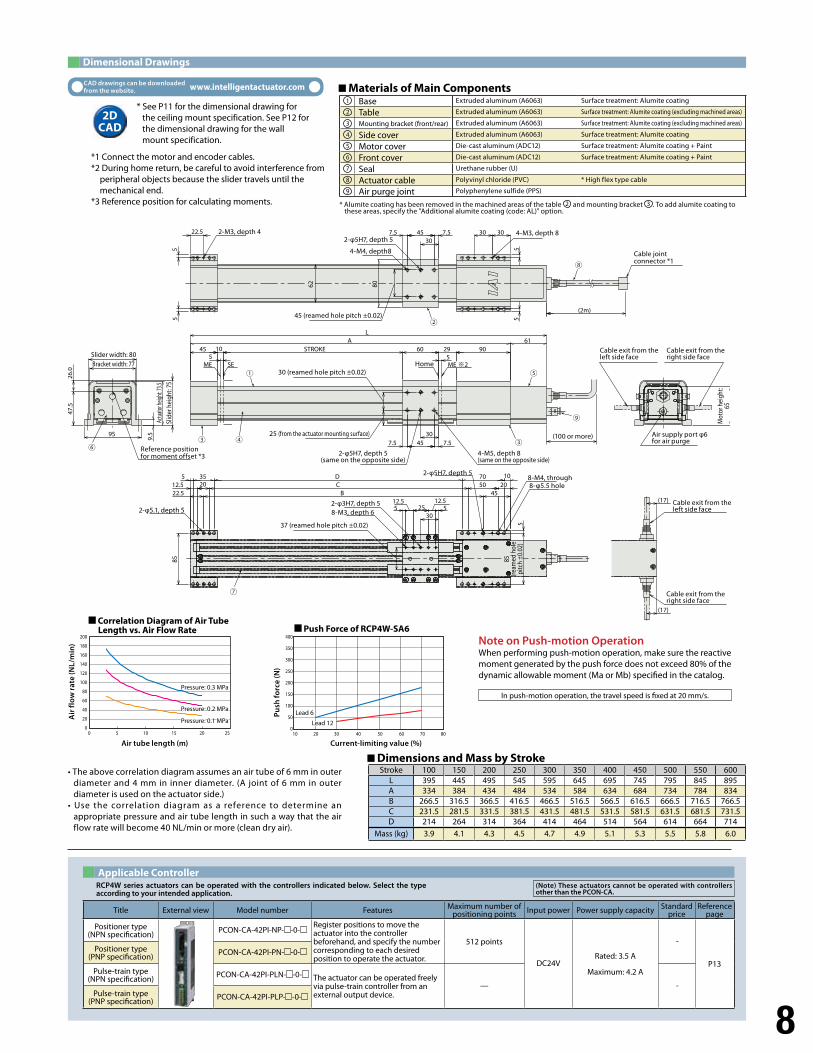
Dimensional Drawings
Applicable Controller
Dimensions and Mass by Stroke
RCP4W series actuators can be operated with the controllers indicated below. Select the type according to your intended application.
Title External view Model number Features Maximum number of positioning points Input power Power supply capacity Standard
priceReference
page
Positioner type(NPN specification) PCON-CA-42PI-NP- -0-
Register positions to move the actuator into the controller beforehand, and specify the number corresponding to each desired position to operate the actuator.
512 points
DC24VRated: 3.5 A
Maximum: 4.2 A
-
P13
Positioner type(PNP specification) PCON-CA-42PI-PN- -0-
Pulse-train type(NPN specification) PCON-CA-42PI-PLN- -0- The actuator can be operated freely
via pulse-train controller from an external output device.
— -Pulse-train type
(PNP specification) PCON-CA-42PI-PLP- -0-
Stroke 100 150 200 250 300 350 400 450 500 550 600L 395 445 495 545 595 645 695 745 795 845 895A 334 384 434 484 534 584 634 684 734 784 834B 266.5 316.5 366.5 416.5 466.5 516.5 566.5 616.5 666.5 716.5 766.5C 231.5 281.5 331.5 381.5 431.5 481.5 531.5 581.5 631.5 681.5 731.5D 214 264 314 364 414 464 514 564 614 664 714
Mass (kg) 3.9 4.1 4.3 4.5 4.7 4.9 5.1 5.3 5.5 5.8 6.0
* See P11 for the dimensional drawing for the ceiling mount specification. See P12 for the dimensional drawing for the wall mount specification.
*1 Connect the motor and encoder cables.*2 During home return, be careful to avoid interference from
peripheral objects because the slider travels until the mechanical end.
*3 Reference position for calculating moments.
2DCAD
• The above correlation diagram assumes an air tube of 6 mm in outer diameter and 4 mm in inner diameter. (A joint of 6 mm in outer diameter is used on the actuator side.)
• Use the correlation diagram as a reference to determine an appropriate pressure and air tube length in such a way that the air flow rate will become 40 NL/min or more (clean dry air).
Note on Push-motion Operation When performing push-motion operation, make sure the reactive moment generated by the push force does not exceed 80% of the dynamic allowable moment (Ma or Mb) specified in the catalog.
In push-motion operation, the travel speed is fixed at 20 mm/s.
Materials of Main Components Base Extruded aluminum (A6063) Surface treatment: Alumite coating
Table Extruded aluminum (A6063) Surface treatment: Alumite coating (excluding machined areas)
Mounting bracket (front/rear) Extruded aluminum (A6063) Surface treatment: Alumite coating (excluding machined areas)
Side cover Extruded aluminum (A6063) Surface treatment: Alumite coating
Motor cover Die-cast aluminum (ADC12) Surface treatment: Alumite coating + Paint
Front cover Die-cast aluminum (ADC12) Surface treatment: Alumite coating + Paint
Seal Urethane rubber (U)
Actuator cable Polyvinyl chloride (PVC) * High flex type cable
Air purge joint Polyphenylene sulfide (PPS)
200
180
160
140
120
100
80
60
40
20
050 10 15 20 25
400
350
300
250
200
150
100
50
010 20 30 40 50 60 70 80
* Alumite coating has been removed in the machined areas of the table 2 and mounting bracket 3 . To add alumite coating to these areas, specify the "Additional alumite coating (code: AL)" option.
(Note) These actuators cannot be operated with controllers other than the PCON-CA.
1
6
2
7
3
8
4
9
5
Correlation Diagram of Air Tube Length vs. Air Flow Rate Push Force of RCP4W-SA6
Air tube length (m) Current-limiting value (%)
Air
flo
w r
ate
(NL/
min
)
Pu
sh fo
rce
(N)
Pressure: 0.3 MPa
Pressure: 0.2 MPaPressure: 0.2 MPa
Pressure: 0.1 MPaPressure: 0.1 MPaLead 5 Lead 6
Lead 10Lead 12
2-M3, depth 42-φ5H7, depth 5
4-M4, depth8
45 (reamed hole pitch ±0.02)
30 (reamed hole pitch ±0.02)
25 (from the actuator mounting surface)
2-φ5H7, depth 5(same on the opposite side)
4-M5, depth 8(same on the opposite side)
4-M3, depth 8
Cable joint connector *1
Slider width: 80Bracket width: 77
Actu
ator h
eight
: 73.5
Slid
er h
eigh
t: 75
Reference position for moment offset *3
Home
(100 or more)
Cable exit from the left side face
Cable exit from the left side face
Cable exit from the right side face
Cable exit from the right side face
Air supply port φ6 for air purge
Mot
or h
eigh
t:65
85
(ream
ed h
ole
pitc
h ±0
.02)
2-φ5.1, depth 5
37 (reamed hole pitch ±0.02)
2-φ3H7, depth 58-M3, depth 6
2-φ5H7, depth 58-M4, through8-φ5.5 hole
9
RCP4W-SA7C
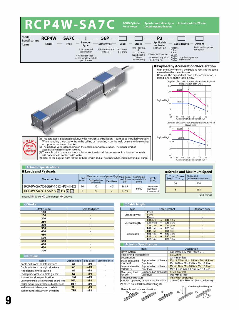
Payload by Acceleration/Deceleration With the RCP4W series, the payload remains the same even when the speed is raised. However, the payload will drop if the acceleration is raised. Check on the table below.
Options
Actuator Specifications
(unit: mm/s)
Actuator Specifications Leads and Payloads Stroke and Maximum Speed
L
L
Ma MaMb Mc McAllowable load moment directions
Overhang load lengths
Model number Lead(mm)
Maximum horizontal payload (kg) Maximum push force
(N)
Positioning repeatability
(mm)Stroke (mm)Supported on
both ends Cantilever
RCP4W-SA7C-I-56P-16- 1 -P3- 2 - 3 16 10 4.5 161.9±0.02
100 to 700(in 50-mm increments)RCP4W-SA7C-I-56P-8- 1 -P3- 2 - 3 8 20 7 337.9
Stroke (mm) Standard price100 -150 -200 -250 -300 -350 -400 -450 -500 -550 -600 -650 -700 -
Item DescriptionDrive system Ball screw φ12 mm, rolled C10Positioning repeatability ±0.02mmLost motion 0.1 mm or lessStatic allowable moment
Supported on both ends Ma: 11.7N•m Mb: 16.6 N•m Mc: 31.8 N•mCantilever Ma: 5.8 N•m Mb: 8.3 N•m Mc: 15.9 N•m
Dynamic allowable moment (*)
Supported on both ends Ma: 6.1 N•m Mb: 8.8 N•m Mc: 16.8 N•mCantilever Ma:3.1 N•m Mb: 4.4 N•m Mc: 8.4 N•m
Overhang load length
Supported on both ends 175 mm or lessCantilever 105 mm or less
Protective structure IP65 (with air purge) Ambient operating temperature, humidity 0 to 40°C, 85% RH or less (Non-condensing)
Name Option code See page Standard priceCable exit from the left side face A1 P4
-Cable exit from the right side face A3 P4Additional alumite coating AL P4 -Food grade grease (edible grease) GE P4
-Non-motor side specification NM P4Ceiling mount (bracket mounted on the left) HFL P4
-Ceiling mount (bracket mounted on the right) HFR P4Wall mount sideways on the left TFL P4Wall mount sideways on the right TFR P4
(*) Based on 5,000 km of traveling life
Noteson
selection
(1) This actuator is designed exclusively for horizontal installation. It cannot be installed vertically. When hanging the actuator from the ceiling or mounting it on the wall, be sure to do so using an optional dedicated bracket.
(2) The payload varies depending on the acceleration/deceleration. The upper limit of acceleration/deceleration is 0.6 G.
(3) The cable joint connector is not splash-proof, so install the connector in a location where it will not come in contact with water.
(4) Refer to the page at right for the air tube length and air flow rate when implementing air purge.
100 to 700(in 50-mm increments)
16 530
8 265
I: Incremental specification
P3:PCON-CA Refer to the option list below.
100 : 100mm
700 : 700mm(Can be set in
50-mm increments.)
* Also select code “I” for the simple absolute
specification.
SA7CType
IEncoder
type
56PMotor type
P3Applicable controllerLead Stroke Cable length Options
RCP4WSeries
8
6
4
2
0
25
15
20
10
5
0
0.60.50.40.30.20.10.0
0.60.50.40.30.20.10.0
33
44
4444
6688
881010
2020
1616
1212
77
66
55
4.54.5
77
4.54.5
3.53.5
Lead6Lead8
Lead16Lead16
Lead8
Lead16Lead16
* The RCP4W can be operated only with the PCON-CA
Model Specification Items
~ N: NoneP: 1 mS: 3 mM: 5 mX : Length designationR : Robot cable
Diagram of Acceleration/Deceleration vs. Payload [Supported at Both Ends]
Payload (kg)
Payload (kg)
Acceleration/deceleration (G)
Acceleration/deceleration (G)
Diagram of Acceleration/Deceleration vs. Payload [Cantilever]
Legend 1 Stroke 2 Cable length 3 Options
StrokeLead
Type Cable symbol Standard price
Standard typeP (1m) -S (3m) -M (5m) -
Special lengthX06 (6m) X10 (10m) -X11 (11m) X15 (15m) -X16 (16m) X20 (20m) -
Robot cable
R01 (1m) R03 (3m) -R04 (4m) R05 (5m) -R06 (6m) R10 (10m) -R11 (11m) R15 (15m) -R16 (16m) R20 (20m) -
~
~
~
~
~
~
~
~
Stroke1
3
Cable length2
ROBO Cylinder Splash-proof slider type Actuator width: 77 mm Pulse motor Coupling specification
56P: Pulse motor size 56
16 : 16mm8 : 8mm
10
STROKE1055
70 29 9091
45
L
7.5557.535
A
ME SE
357.5557.5 303022.5
555
5
5
1070
5153015
2035
5B
CD5
12.5
100
22.5
110
9.5
4520
35
(2m)
77 95
(17)
(17)
53.0
27.5
50
CAD drawings can be downloaded from the website. www.intelligentactuator.com
Dimensional Drawings
Applicable Controller
Dimensions and Mass by Stroke
RCP4W series actuators can be operated with the controllers indicated below. Select the type according to your intended application.
Title External view Model number Features Maximum number of positioning points Input power Power supply capacity Standard
priceReference
page
Positioner type(NPN specification) PCON-CA-56PI-NP- -0-
Register positions to move the actuator into the controller beforehand, and specify the number corresponding to each desired position to operate the actuator.
512 points
DC24VRated: 3.5 A
Maximum: 4.2 A
-
P13
Positioner type(PNP specification) PCON-CA-56PI-PN- -0-
Pulse-train type(NPN specification) PCON-CA-56PI-PLN- -0- The actuator can be operated freely
via pulse-train controller from an external output device.
— -Pulse-train type
(PNP specification) PCON-CA-56PI-PLP- -0-
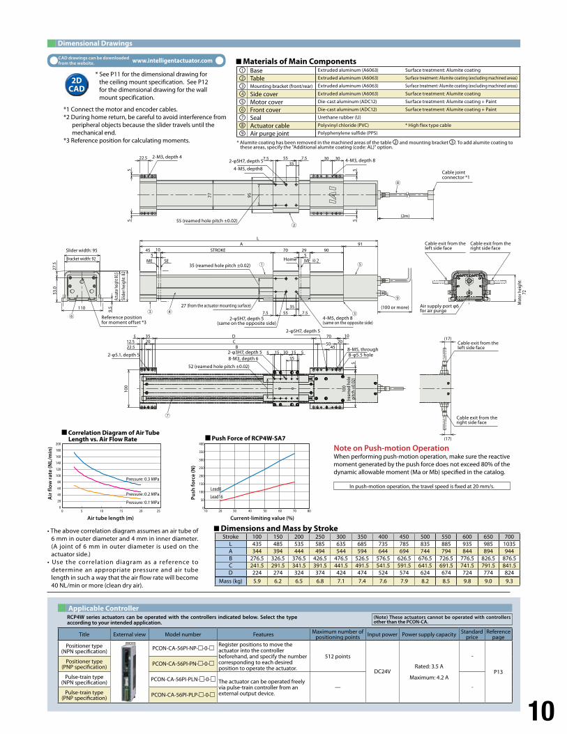
Stroke 100 150 200 250 300 350 400 450 500 550 600 650 700L 435 485 535 585 635 685 735 785 835 885 935 985 1035A 344 394 444 494 544 594 644 694 744 794 844 894 944B 276.5 326.5 376.5 426.5 476.5 526.5 576.5 626.5 676.5 726.5 776.5 826.5 876.5C 241.5 291.5 341.5 391.5 441.5 491.5 541.5 591.5 641.5 691.5 741.5 791.5 841.5D 224 274 324 374 424 474 524 574 624 674 724 774 824
Mass (kg) 5.9 6.2 6.5 6.8 7.1 7.4 7.6 7.9 8.2 8.5 9.8 9.0 9.3
* See P11 for the dimensional drawing for the ceiling mount specification. See P12 for the dimensional drawing for the wall mount specification.
*1 Connect the motor and encoder cables.*2 During home return, be careful to avoid interference from
peripheral objects because the slider travels until the mechanical end.
*3 Reference position for calculating moments.
2DCAD
• The above correlation diagram assumes an air tube of 6 mm in outer diameter and 4 mm in inner diameter. (A joint of 6 mm in outer diameter is used on the actuator side.)
• Use the correlation diagram as a reference to determine an appropriate pressure and air tube length in such a way that the air flow rate will become 40 NL/min or more (clean dry air).
Note on Push-motion Operation When performing push-motion operation, make sure the reactive moment generated by the push force does not exceed 80% of the dynamic allowable moment (Ma or Mb) specified in the catalog.
In push-motion operation, the travel speed is fixed at 20 mm/s.
Materials of Main Components Base Extruded aluminum (A6063) Surface treatment: Alumite coating
Table Extruded aluminum (A6063) Surface treatment: Alumite coating (excluding machined areas)
Mounting bracket (front/rear) Extruded aluminum (A6063) Surface treatment: Alumite coating (excluding machined areas)
Side cover Extruded aluminum (A6063) Surface treatment: Alumite coating
Motor cover Die-cast aluminum (ADC12) Surface treatment: Alumite coating + Paint
Front cover Die-cast aluminum (ADC12) Surface treatment: Alumite coating + Paint
Seal Urethane rubber (U)
Actuator cable Polyvinyl chloride (PVC) * High flex type cable
Air purge joint Polyphenylene sulfide (PPS)
200
180
160
140
120
100
80
60
40
20
050 10 15 20 25
400
350
300
250
200
150
100
50
010 20 30 40 50 60 70 80
Lead8Lead8
Lead16Lead16
* Alumite coating has been removed in the machined areas of the table 2 and mounting bracket 3 . To add alumite coating to these areas, specify the "Additional alumite coating (code: AL)" option.
(Note) These actuators cannot be operated with controllers other than the PCON-CA.
1
6
2
7
3
8
4
9
5
Correlation Diagram of Air Tube Length vs. Air Flow Rate Push Force of RCP4W-SA7
Air tube length (m) Current-limiting value (%)
Air
flo
w r
ate
(NL/
min
)
Pu
sh fo
rce
(N)
Pressure: 0.3 MPa
Pressure: 0.2 MPaPressure: 0.2 MPa
Pressure: 0.1 MPaPressure: 0.1 MPa
2-M3, depth 42-φ5H7, depth 5
4-M5, depth8
55 (reamed hole pitch ±0.02)
35 (reamed hole pitch ±0.02)
27 (from the actuator mounting surface)
2-φ5H7, depth 5(same on the opposite side)
4-M5, depth 8(same on the opposite side)
4-M3, depth 8
Cable joint connector *1
Slider width: 95
Bracket width: 92
Actu
ator h
eight
: 80.5
Slid
er h
eigh
t: 82
Reference position for moment offset *3
Home
(100 or more)
Cable exit from the left side face
Cable exit from the left side face
Cable exit from the right side face
Cable exit from the right side face
Air supply port φ6 for air purge
Mot
or h
eigh
t:72
100
(ream
ed h
ole
pitc
h ±0
.02)
2-φ5.1, depth 5
52 (reamed hole pitch ±0.02)
2-φ3H7, depth 58-M3, depth 6
2-φ5H7, depth 5
8-M5, through8-φ5.5 hole
11
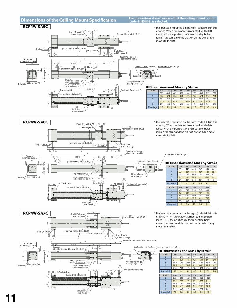
Dimensions of the Ceiling Mount Specification
5 5STROKE10 50 29 9045
A 61L
25
7.5357.519
25
64
1.5
63.5
MEME SE
55
257.5357.5
35
70
452010
5070
BCD355
2012.522.5
85
5
2551020105
30
16
3030
16
7.5 30
(17)
36
35 36
95
6
RCP4W-SA5C
5 5STROKE10 60 29 90
61A45
L
30
7.5457.5
21.5
73.5
1.5
73.5
MEME SE
62
30
7.5457.5
80
5
4520501070
BCD
2012.5355
22.5
95
16
30305
12.525
12.55
16
7.5 30
(17)
40.5
40
40.5
105
95
45
30
6
3037
STROKE55
10 70
7.5557.535
45 29 90A 91
L
21.5
86
1.5
80.5
MEME SE
357.555
55
7.5
95
10
4520
7050
BCD
2035
22.512.55
5
110
77
515301535
5
(17)
3030
16
7.5 30
1648
47.5 48
120
86
6
110
35
52
RCP4W-SA6C
RCP4W-SA7C
The dimensions shown assume that the ceiling mount option (code: HFR/HFL) is selected.
* The bracket is mounted on the right (code: HFR) in this drawing. When the bracket is mounted on the left (code: HFL), the positions of the mounting holes remain the same and the bracket on the side simply moves to the left.
* The bracket is mounted on the right (code: HFR) in this drawing. When the bracket is mounted on the left (code: HFL), the positions of the mounting holes remain the same and the bracket on the side simply moves to the left.
* The bracket is mounted on the right (code: HFR) in this drawing. When the bracket is mounted on the left (code: HFL), the positions of the mounting holes remain the same and the bracket on the side simply moves to the left.
Stroke 100 150 200 250 300 350 400 450 500L 385 435 485 535 585 635 685 735 785A 324 374 424 474 524 574 624 674 724B 256.5 306.5 356.5 406.5 456.5 506.5 556.5 606.5 656.5C 221.5 271.5 321.5 371.5 421.5 471.5 521.5 571.5 621.5D 204 254 304 354 404 454 504 554 604
Mass (kg) 2.8 2.9 3.1 3.2 3.4 3.5 3.7 3.8 4.0
Stroke 100 150 200 250 300 350L 395 445 495 545 595 645A 334 384 434 484 534 584B 266.5 316.5 366.5 416.5 466.5 516.5C 231.5 281.5 331.5 381.5 431.5 481.5D 214 264 314 364 414 464
Mass (kg) 3.9 4.1 4.3 4.5 4.7 4.9
Stroke 400 450 500 550 600L 695 745 795 845 895A 634 684 734 784 834B 566.5 616.5 666.5 716.5 766.5C 531.5 581.5 631.5 681.5 731.5D 514 564 614 664 714
Mass (kg) 5.1 5.3 5.5 5.8 6.0
Stroke 100 150 200 250 300 350 400L 435 485 535 585 635 685 735A 344 394 444 494 544 594 644B 276.5 326.5 376.5 426.5 476.5 526.5 576.5C 241.5 291.5 341.5 391.5 441.5 491.5 541.5D 224 274 324 374 424 474 524
Mass (kg) 5.9 6.2 6.5 6.8 7.1 7.4 7.6
Stroke 450 500 550 600 650 700L 785 835 885 935 985 1035A 694 744 794 844 894 944B 626.5 676.5 726.5 776.5 826.5 876.5C 591.5 641.5 691.5 741.5 791.5 841.5D 574 624 674 724 774 824
Mass (kg) 7.9 8.2 8.5 8.8 9.0 9.3
Actuator mounting surface
Slid
er h
eig
ht: 6
5
4-M4, depth 6
8-M5, through
Depth 84-M4, depth 6 (same on the opposite side)
8-M3, depth 6
2-M3, depth 6
2-φ4H7, depth 4 (same on the opposite side)
2-φ3H7, depth 5
2-φ4H7, depth 4
2-φ5.1, depth 52-φ5H7, depth 5
(reamed hole pitch ±0.02)
85 (reamed hole pitch ±0.02)
8-φ5.5 hole
Slider width: 70Bracket
Home
(100mm or more to a bend in the cable)
Cable exit from the left
Cable exit from the left
Cable exit from the right
Air supply port φ6 for air purge
(reamed hole pitch ±0.02)
(reamed hole pitch ±0.02)
2-M3, depth6 Dimensions and Mass by Stroke
Dimensions and Mass by Stroke
Dimensions and Mass by Stroke
Actuator mounting surface
Slid
er h
eig
ht: 7
5
4-M5, depth 8
8-M5, through
4-M5, depth 8 (same on the opposite side)
8-M3, depth 6
2-M3, depth 6
2-φ5H7, depth 5 (same on the opposite side)
2-φ3H7, depth 5
2-φ5H7, depth 5
2-φ5.1, depth 5 2-φ5H7, depth 5(reamed hole pitch ±0.02)
(reamed hole pitch ±0.02)
8-φ5.5 hole
Slider width: 80Bracket
Home Cable exit from the left
Cable exit from the left
Cable exit from the right
Air supply port φ6 for air purge
(reamed hole pitch ±0.02)
(reamed hole pitch ±0.02)
2-M3, depth6
Actuator mounting surface
Slid
er h
eig
ht: 8
2
4-M5, depth 8
8-M5, through
4-M5, depth 8 (same on the opposite side)
8-M3, depth 6
2-M3, depth 6
2-φ5H7, depth 5 (same on the opposite side)
2-φ3H7, depth 5
2-φ5H7, depth 5
2-φ5.1, depth 52-φ5H7, depth 5
(reamed hole pitch ±0.02)
(reamed hole pitch ±0.02)
8-φ5.5 hole
Slider width: 95Bracket
HomeCable exit from the left
Cable exit from the left
Cable exit from the right
Air supply port φ6 for air purge
(reamed hole pitch ±0.02)
(reamed hole pitch ±0.02)
2-M3, depth6
(100mm or more to a bend in the cable)
(100mm or more to a bend in the cable)
12
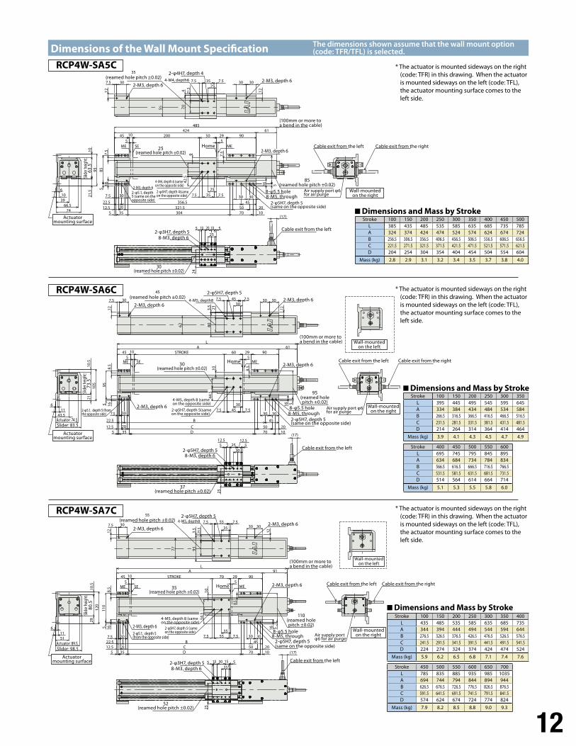
Dimensions of the Wall Mount Specification
5 520010
356.522.5
5
85
29 905045424 61
485
2010
5070
7.5357.5
321.52012.5355 304
5
7.5
7.5
9 7.5
MEME SE
3030
12
7.5357.5
21.54
7.5 30
12
(17)
51020105
246103966.574
21.5
1095
30
453030
16
55 70
16
2542
.5
25
25
RCP4W-SA5C
5STROKE
510
95
60 29 90A
4561
L
45 7.57.5
201070
50
16 5
B
CD
20355
12.5
22.5
7.5
1658.5
10 8.5
MEME SE
3030
12
7.5457.5
3.5
21
7.5 30
12
512.5
2512.55
25
(17)
1143.5
6
2110
.510
5
62 80
30
30
30
30 30
45
30
44.5
RCP4W-SA6C
STROKE55
10
B22.5
70
7.5557.5
29 90A
45
L91
5
205070 10
CD
2035
12.55
16
7.5
16511
08.5
10
8.5
MEME SE
7.5557.5
3.5
12
3030
23.5
12
7.5 30
51530155
(17)
25
2912
0
11
10.5
6
51
9577
35
35
303045
35
54.5
30
RCP4W-SA7C
The dimensions shown assume that the wall mount option (code: TFR/TFL) is selected.
* The actuator is mounted sideways on the right (code: TFR) in this drawing. When the actuator is mounted sideways on the left (code: TFL), the actuator mounting surface comes to the left side.
* The actuator is mounted sideways on the right (code: TFR) in this drawing. When the actuator is mounted sideways on the left (code: TFL), the actuator mounting surface comes to the left side.
* The actuator is mounted sideways on the right (code: TFR) in this drawing. When the actuator is mounted sideways on the left (code: TFL), the actuator mounting surface comes to the left side.
Stroke 100 150 200 250 300 350 400 450 500L 385 435 485 535 585 635 685 735 785A 324 374 424 474 524 574 624 674 724B 256.5 306.5 356.5 406.5 456.5 506.5 556.5 606.5 656.5C 221.5 271.5 321.5 371.5 421.5 471.5 521.5 571.5 621.5D 204 254 304 354 404 454 504 554 604
Mass (kg) 2.8 2.9 3.1 3.2 3.4 3.5 3.7 3.8 4.0
Stroke 100 150 200 250 300 350L 395 445 495 545 595 645A 334 384 434 484 534 584B 266.5 316.5 366.5 416.5 466.5 516.5C 231.5 281.5 331.5 381.5 431.5 481.5D 214 264 314 364 414 464
Mass (kg) 3.9 4.1 4.3 4.5 4.7 4.9
Stroke 400 450 500 550 600L 695 745 795 845 895A 634 684 734 784 834B 566.5 616.5 666.5 716.5 766.5C 531.5 581.5 631.5 681.5 731.5D 514 564 614 664 714
Mass (kg) 5.1 5.3 5.5 5.8 6.0
Stroke 100 150 200 250 300 350 400L 435 485 535 585 635 685 735A 344 394 444 494 544 594 644B 276.5 326.5 376.5 426.5 476.5 526.5 576.5C 241.5 291.5 341.5 391.5 441.5 491.5 541.5D 224 274 324 374 424 474 524
Mass (kg) 5.9 6.2 6.5 6.8 7.1 7.4 7.6
Stroke 450 500 550 600 650 700L 785 835 885 935 985 1035A 694 744 794 844 894 944B 626.5 676.5 726.5 776.5 826.5 876.5C 591.5 641.5 691.5 741.5 791.5 841.5D 574 624 674 724 774 824
Mass (kg) 7.9 8.2 8.5 8.8 9.0 9.3
Dimensions and Mass by Stroke
Dimensions and Mass by Stroke
Dimensions and Mass by Stroke
8-M5, through
4-M4, depth 6 (same on the opposite side)
2-M3, depth 6
2-φ5.1, depth 5 (same on the opposite side)
2-φ5H7, depth 5(same on the opposite side)
2-φ4H7, depth 4(same on the opposite side)
25(reamed hole pitch ±0.02)
8-φ5.5 hole
Home
Cable exit from the left
Cable exit from the left Cable exit from the right
Air supply port φ6 for air purge
85(reamed hole pitch ±0.02)
Actuator mounting surface
Slide
r heig
ht:
63.5
2-M3, depth 62-M3, depth 6
8-M3, depth 6
2-M3, depth 6
2-φ3H7, depth 5
2-φ4H7, depth 435 (reamed hole pitch ±0.02)
4-M4, depth6
Wall-mounted on the right
30(reamed hole pitch ±0.02)
8-M5, through
4-M5, depth 8 (same on the opposite side)
2-M3, depth 6
2-φ5H7, depth 5(same on the opposite side)
2-φ5H7, depth 5(same on the opposite side)
30(reamed hole pitch ±0.02)
8-φ5.5 hole
Home
Cable exit from the left
Cable exit from the left Cable exit from the right
Air supply port φ6 for air purge
95(reamed hole pitch ±0.02)
Actuator mounting surface
Slide
r heig
ht:
73.5
2-M3, depth 62-M3, depth 6
8-M3, depth 6
2-M3, depth 6
2-φ5H7, depth 5
2-φ5H7, depth 5
2-φ5H7, depth 5
45 (reamed hole pitch ±0.02)
4-M5, depth8
Wall-mounted on the right
Wall-mounted on the left
37(reamed hole pitch ±0.02)
Actuator: 74.5Slider: 83.5
2-φ5.1, depth 5 (from the opposite side)
8-M5, through
4-M5, depth 8 (same on the opposite side)
2-M3, depth 6
2-φ5H7, depth 5(same on the opposite side)
2-φ5H7, depth 5 (same on the opposite side)
35(reamed hole pitch ±0.02)
8-φ5.5 hole
Home
Cable exit from the left
Cable exit from the left Cable exit from the right
Air supply port φ6 for air purge
110(reamed hole pitch ±0.02)
Actuator mounting surface
Slide
r heig
ht:
80.5
2-M3, depth 62-M3, depth 6
8-M3, depth 6
2-M3, depth 6
2-φ3H7, depth 5
55 (reamed hole pitch ±0.02) 4-M5, depth8
Wall-mounted on the right
Wall-mounted on the left
52(reamed hole pitch ±0.02)
Actuator: 89.5Slider: 98.5
2-φ5.1, depth 5(from the opposite side)
(100mm or more to a bend in the cable)
(100mm or more to a bend in the cable)
(100mm or more to a bend in the cable)
13
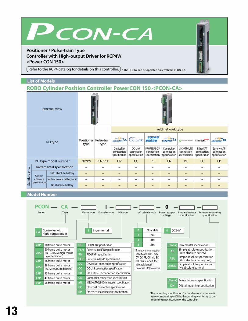
I Incremental
(Blank) Screw fastening specification
DN DIN rail mounting specification
0 DC24VCA Controller with high-output driver
20P 20 frame pulse motor
20SP20 frame pulse motor (RCP3-RA2A high-thrust type dedicated)
28P 28 frame pulse motor
28SP 28 frame pulse motor(RCP2-RA3C dedicated)
35P 35 frame pulse motor
42P 42 frame pulse motor
56P 56 frame pulse motor
0 No cable
2 2m
3 3m
5 5m (Blank) Incremental specification
AB Simple absolute specification(With absolute battery)
ABU Simple absolute specification(With absolute battery unit)
ABUN Simple absolute specification(No absolute battery)
NP PIO (NPN) specification
PLN Pulse-train (NPN) specification
PN PIO (PNP) specification
PLP Pulse-train (PNP) specification
DV DeviceNet connection specification
CC CC-Link connection specification
PR PROFIBUS-DP connection specification
CN CompoNet connection specification
ML MECHATROLINK connection specification
EC EtherCAT connection specification
EP EtherNet/IP connection specification
Series Type Motor type Encoder type I/O type I/O cable length Power supply voltage
Simple absolute specification
Actuator mounting specification
I 0PCON CA
*The mounting specification for the absolute battery unit (screws mounting or DIN rail mounting) conforms to the mounting specification for the controller.
*If a network connection specification (I/O type-
DV, CC, PR, CN, ML, EC or EP) is selected, the
I/O cable length becomes "0" (no cable).
Model Number
* The RCP4W can be operated only with the PCON-CA.
Positioner / Pulse-train Type Controller with High-output Driver for RCP4W <Power CON 150>
Refer to the RCP4 catalog for details on this controller.
External view
I/O type Positionertype
Pulse-traintype
Field network type
DeviceNet connection
specification
CC-Link connection
specification
PROFIBUS-DP connection
specification
CompoNet connection
specification
MECHATROLINK connection
specification
EtherCAT connection
specification
EtherNet/IP connection
specification
I/O type model number NP/PN PLN/PLP DV CC PR CN ML EC EP
Incremental specification – – – – – – – – –
Simpleabsolute
specification
with absolute battery – – – – – – – – –
with absolute battery unit – – – – – – – – –
No absolute battery – – – – – – – – –Stan
dard
pric
e
List of Models
ROBO Cylinder Position Controller PowerCON 150 <PCON-CA>
14
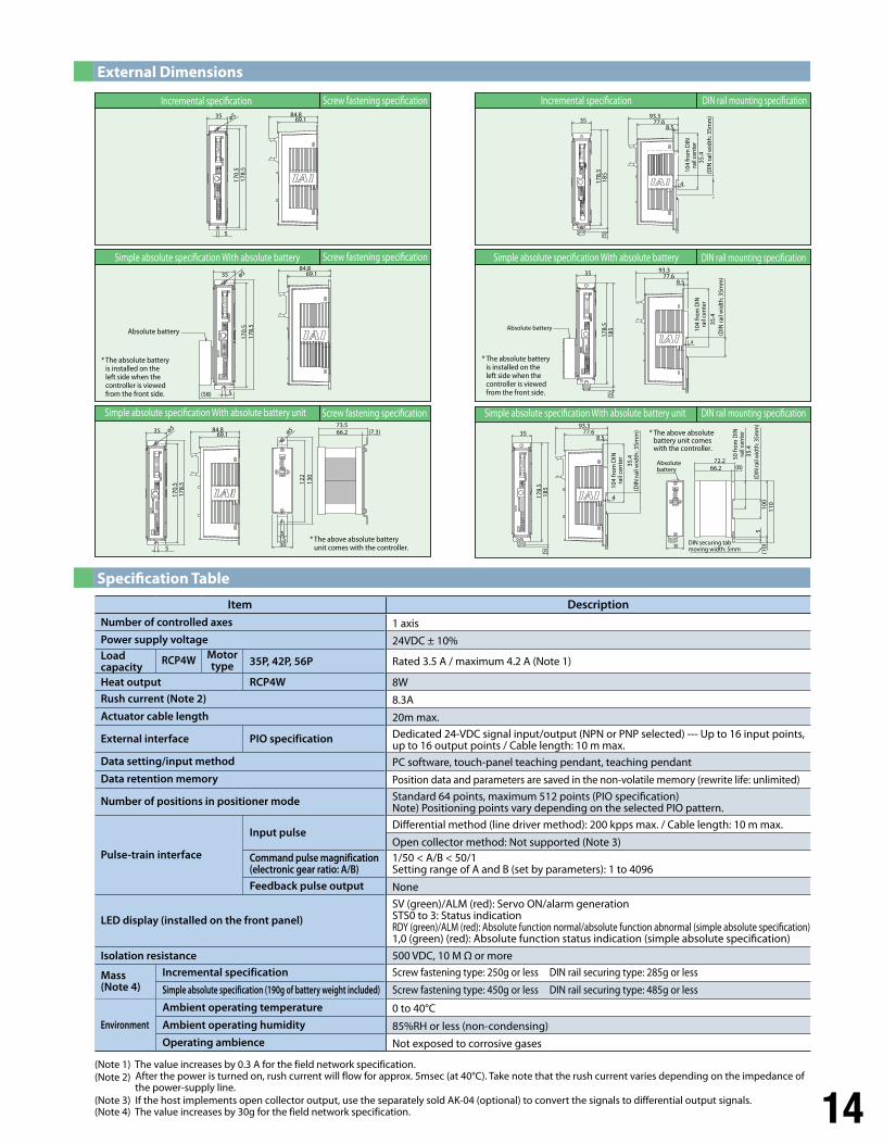
External Dimensions
(Note 1) The value increases by 0.3 A for the field network specification.(Note 2) After the power is turned on, rush current will flow for approx. 5msec (at 40°C). Take note that the rush current varies depending on the impedance of
the power-supply line. (Note 3) If the host implements open collector output, use the separately sold AK-04 (optional) to convert the signals to differential output signals. (Note 4) The value increases by 30g for the field network specification.
Specification Table
Item DescriptionNumber of controlled axes 1 axisPower supply voltage 24VDC ± 10%Load capacity
RCP4W Motor type 35P, 42P, 56P Rated 3.5 A / maximum 4.2 A (Note 1)
Heat output RCP4W 8W
Rush current (Note 2) 8.3A
Actuator cable length 20m max.
External interface PIO specification Dedicated 24-VDC signal input/output (NPN or PNP selected) --- Up to 16 input points, up to 16 output points / Cable length: 10 m max.
Data setting/input method PC software, touch-panel teaching pendant, teaching pendant
Data retention memory Position data and parameters are saved in the non-volatile memory (rewrite life: unlimited)
Number of positions in positioner mode Standard 64 points, maximum 512 points (PIO specification)Note) Positioning points vary depending on the selected PIO pattern.
Pulse-train interface
Input pulseDifferential method (line driver method): 200 kpps max. / Cable length: 10 m max.
Open collector method: Not supported (Note 3)Command pulse magnification (electronic gear ratio: A/B)
1/50 < A/B < 50/1Setting range of A and B (set by parameters): 1 to 4096
Feedback pulse output None
LED display (installed on the front panel)SV (green)/ALM (red): Servo ON/alarm generation STS0 to 3: Status indication RDY (green)/ALM (red): Absolute function normal/absolute function abnormal (simple absolute specification) 1,0 (green) (red): Absolute function status indication (simple absolute specification)
Isolation resistance 500 VDC, 10 M Ω or more
Mass(Note 4)
Incremental specification Screw fastening type: 250g or less DIN rail securing type: 285g or less
Simple absolute specification (190g of battery weight included) Screw fastening type: 450g or less DIN rail securing type: 485g or less
Environment
Ambient operating temperature 0 to 40°C
Ambient operating humidity 85%RH or less (non-condensing)Operating ambience Not exposed to corrosive gases
Incremental speci�cation Incremental speci�cationScrew fastening speci�cation
Screw fastening speci�cation
Screw fastening speci�cation DIN rail mounting speci�cation
DIN rail mounting speci�cation
DIN rail mounting speci�cation
Simple absolute speci�cation With absolute battery
Simple absolute speci�cation With absolute battery unit Simple absolute speci�cation With absolute battery unit
Simple absolute speci�cation With absolute battery
* The above absolute battery unit comes with the controller.
122
51530
66.273.5
(7.3)
130
178.
517
0.5
35
5
84.869.1
ø5ø5
178.
517
0.5
35
Absolute battery
* The absolute battery is installed on the left side when the controller is viewed from the front side.
* The absolute battery is installed on the left side when the controller is viewed from the front side.5
84.869.1ø5
(58)
178.
517
0.5
35
5
84.869.1ø5
* The above absolute battery unit comes with the controller.
35
(5)
185
178.
5
93.377.6
8.5
4
104
from
DIN
rail
cent
er
(DIN
rail
wid
th: 3
5mm
)
(DIN
rail
wid
th: 3
5mm
)
50 fr
om D
INra
il ce
nter
104
from
DIN
rail
cent
er
104
from
DIN
rail
cent
er
35.4
(DIN
rail
wid
th: 3
5mm
)
DIN securing tabmoving width: 5mm
Absolute battery
Absolute battery
(10)
100
110
35.4
35.4
(DIN
rail
wid
th: 3
5mm
)35
.4
5
72.2
30
66.2 (6)
35
185
178.
5(5
)
93.377.6
8.5
35
(5)
93.377.6
8.5
185
178.
5
4
4
IAI America, Inc. IAI Industrieroboter GmbHOber der Roth 4, D-65824 Schwalbach am Taunus, GermanyHeadquarters: 2690 W. 237th Street Torrance, CA 90505 (800) 736-1712
Chicago Office: 1261 Hamilton Parkway Itasca, IL 60143 (800) 944-0333Atlanta Office: 1220 Kennestone Circle, Suite 108, Marietta, GA 30066 (888) 354-9470 www.intelligentactuator.comThe information contained in this product brochure may change without prior notice due to product improvements.
CJ0189-2A-UST-2-0214
Related Documents