Durable Concrete for Infrastructure under Severe Conditions Smart Admixtures, Self-responsiveness and Nano-additions Proceedings Het Pand, Ghent, Belgium 10-11 September 2019

Welcome message from author
This document is posted to help you gain knowledge. Please leave a comment to let me know what you think about it! Share it to your friends and learn new things together.
Transcript
Durable Concrete for Infrastructure
under Severe Conditions Smart Admixtures,
Self-responsiveness and Nano-additions
Proceedings
Het Pand, Ghent, Belgium
10-11 September 2019
Durable Concrete for Infrastructure
under Severe Conditions
Smart Admixtures, Self-responsiveness and
Nano-additions
Proceedings
10-11 September 2019, Ghent
Editors
Maria Adelaide Araújo, Ghent University
Nele De Belie, Ghent University
Kim Van Tittelboom, Ghent University
Publisher
Magnel Laboratory for Concrete Research
Technologiepark Zwijnaarde 60
9052 Ghent

All rights reserved. No part of this publication or the information contained herein may be reproduced, stored in a retrieval system, or transmitted in any form or by any means, electronic, mechanical, recording or otherwise, without written prior permission from the publisher. ISBN: 978-9-463-88638-3
Scientific Committee
Nele De Belie (UGent, BE)
Sandra Van Vlierberghe (UGent, BE)
Kim Van Tittelboom (UGent, BE)
Maria Adelaide Araújo (UGent, BE)
Els Mannekens (ChemStream, BE)
Geert Deroover (ChemStream, BE)
Christian Simon (Sintef, NO)
Monika Pilz (Sintef, NO)
Philippe Maincon (Sintef, NO)
Harald Justnes (Sintef, NO)
Tor Arne Hammer (Sintef, NO)
Ole Swang (Sintef, NO)
Costas Charitidis (NTUA, GR)
loannis Kartsonakis (NTUA, GR)
Danalia Karaxi (NTUA, GR)
Daniel Höche (HZG, DE)
Mário Ferreira (UAVR, PT)
Alexandre Bastos (UAVR, PT)
João Tedim (UAVR, PT)
Raul Pina-Zapardiel (Acciona, ES)
Valle Choza-Ligero (Acciona, ES)
Jose Vera-Agullo (Acciona, ES)
Urs Müeller (CBI, SE)
Nadia Al-Ayish (CBI, SE)
Maria Cruz Alonso (CSIC, ES)
Javier Puentes (CSIC, ES)
Juan Antonio Alduncin (IK4-Cidetec, ES)
Kjell Tore Fosså (Kvaerner, NO)
Frederico Maia (SMT, PT)
Emmanuel Gallucci (Sika, CH)
Arnd Eberhardt (Sika, CH)
Sara Irico (Dyckerhoff, DE)
Dirk Qvaeschning (Dyckerhoff, DE)
Peter Lundqvist (Vattenfall, SE)
Local organizing committee
N. De Belie, K. Van Tittelboom, S. Van Vlierberghe, L. De Meyst, M. Araújo, M.
Reunes, J. Mortier, C. Malfait
Preface
The continuously growing world population and wide-spread industrialization increase the need for sustainable infrastructure. The construction industry currently is responsible for an important part of the environmental impacts related to the use of natural resources and energy, the production of waste, and greenhouse gas emissions. To minimize these impacts, our civil engineering structures need to become more long-lasting and smart. Since concrete is the most used construction material, increasing the durability of concrete structures is an important goal in this respect. To obtain such enhanced durability and sustainability, in the last decade several smart admixtures have been developed to impart self-responsiveness to this material, including self-sensing, self-curing, and self-healing. Carbon nanofibers and nanotubes have been used to make the concrete self-sensing and report when damage is about to occur or has occurred already. Layered double hydroxides can capture aggressive agents intruding into the concrete and can release corrosion inhibitors to prevent damage. Superabsorbent polymers have been developed to provoke internal curing and hence can mitigate autogenous shrinkage cracks; they can also self-seal cracks from intruding liquids and stimulate self-healing through the deposition of calcium carbonate and binder hydration products. Micro- and macro-capsules containing mineral or polymeric healing agents can provide autonomic self-healing properties. With the International Conference on Durable Concrete for Infrastructure under Severe Conditions – smart admixtures, self-responsiveness and nano-additions, we want to offer participants a full overview of the most recent advances in the development of these smart admixtures. The compatibility of the smart admixtures with other concrete components and the effects on fresh and hardened concrete properties are considered. Modelling of the hydration reactions and microstructure formation in the novel durable concrete, of the activation of smart properties, of the service life in specific environments, and of environmental impacts, is of importance as well. Existing and emerging energy technologies also require that these materials perform in more and more extreme operating conditions as they are installed in sub-arctic/arctic areas (low temperatures, ice-abrasion), desert areas (high temperatures), along coast lines (high chloride contents), deep-sea or underground (large temperature gradients and high pressure). Evaluation of the resistance to extreme conditions is also included. We hope that you will enjoy this opportunity to share your latest experiences, to discover new avenues for exploration, to meet colleagues, and of course to enjoy the beautiful historic city of Ghent. Nele De Belie, Kim Van Tittelboom, Sandra Van Vlierberghe, Adelaide Araújo, Laurence De Meyst
Session 1 Development of smart admixtures with
active internal curing, self-sealing or self-healing properties
2
Smart admixtures with active functionality in concrete
E.K. Karaxi1, I.Kanellopoulou1, I.A Kartsonakis1, C.A. Charitidis*1
1Research Unit of Advanced, Composite, Nanomaterials and Nanotechnology, School of Chemical Engineering, National Technical University of Athens, 9 Heroon Polytechniou st., Zografos, Athens, GR-15773, Greece – email: [email protected]; [email protected]; [email protected] *corresponding author – email: [email protected]
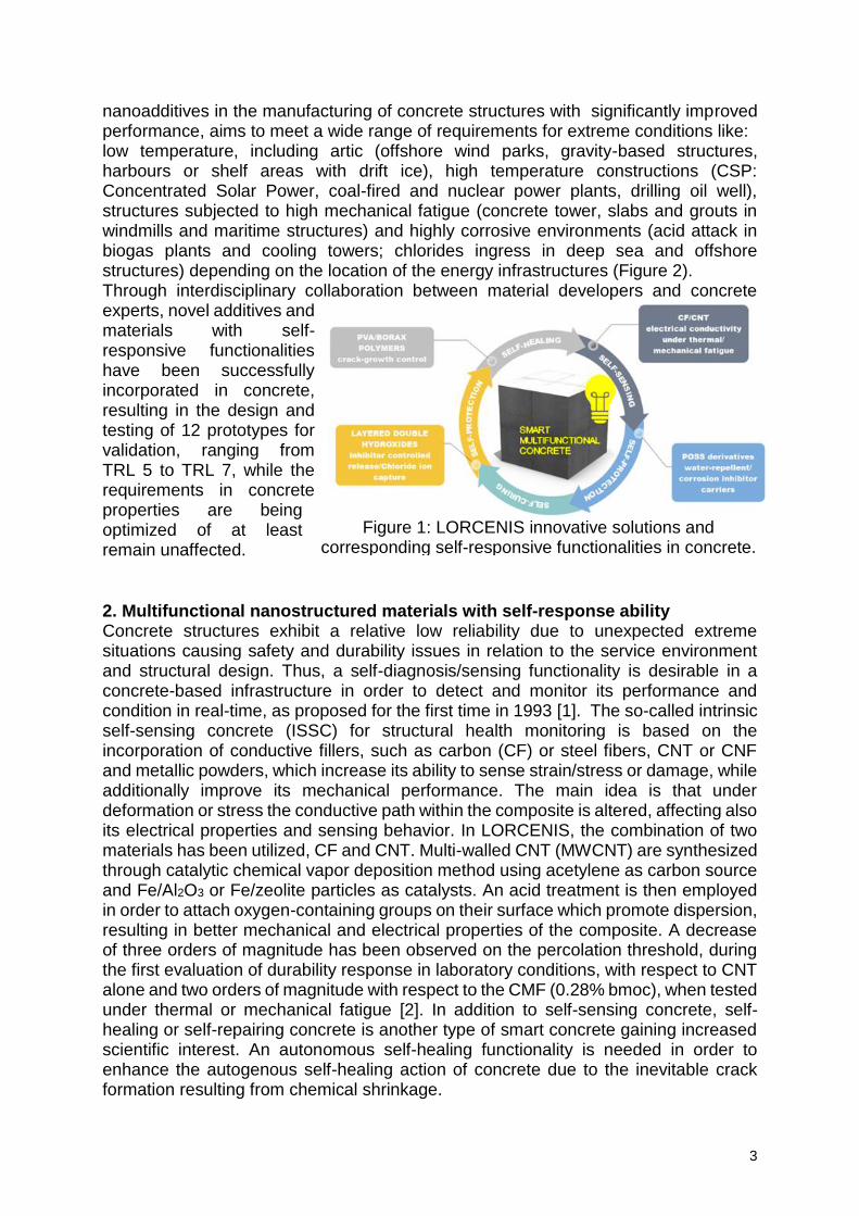
Abstract Concrete can be nano-engineered by the incorporation of a variety of nano- and micro-sized structures with superior characteristics, such as hydrogels/superabsorbent polymers, carbon-based fillers such as carbon nanotubes (CNT) and nanofibers (CNF), hybrid organic-inorganic nanostructures, layered double hydroxides, nano/ microcapsules and self-healing polymers. These materials contribute to the development of a new generation of tailored, multifunctional concrete and add self-responsive capabilities especially to concrete structures working under severe conditions. Keywords: self-healing, self-sensing, self-curing, multifunctional, concrete 1. Introduction Conventional concrete is a multiphase, multicomponent and multiscale composite, with characteristics which are evolving through time due to the progressive and long-term nature of hydration reaction. It has very limited functional capabilities and serves mainly as a structural material due to its superior compressive strength and durability. In comparison to these traditional materials, multifunctional nano-modified cementitious composites can be developed, if properly designed, in order to improve or tailor their characteristics to achieve longer service-lives, less maintenance and repair costs, less safety and risk issues and much more. This sustainability-centered approach, will contribute to a low carbon, circular economy with the reduction of CO2 emissions and construction and demolition waste, which pose two of the major environmental impacts of the building sector. With an increasing demand of energy worldwide, LORCENIS aims at developing long lasting reinforced concrete for energy infrastructures subjected to extreme operating conditions. Many intelligent functionalities can be designed and achieved through detailed design and in-depth knowledge in cement properties, according to processing and application requirements. LORCENIS focuses in several multifunctional damage-responsive strategies, (i) self-diagnosis, (ii) self-healing, (iii) self-curing and (iv) self-protection (Figure 1). The highly ambitious nature of the project is based on the goal to establish new breakthroughs in construction industry by improving several properties of the current state-of-the-art concrete technologies, self-compacting concrete (SCC) and ultra-high-performance concrete (UHPC) to exceed 100 years of service-life. In order to improve the durability of the reinforced concrete formulations, a thorough analysis has been conducted by the industrial partners in the project, in order to identify the mechanism of degradation related to each targeted exposure environment, identify the real market needs and understand the current challenges and limitations. Four environmental scenarios will demonstrate the project developments. The integration of multi-functional
3
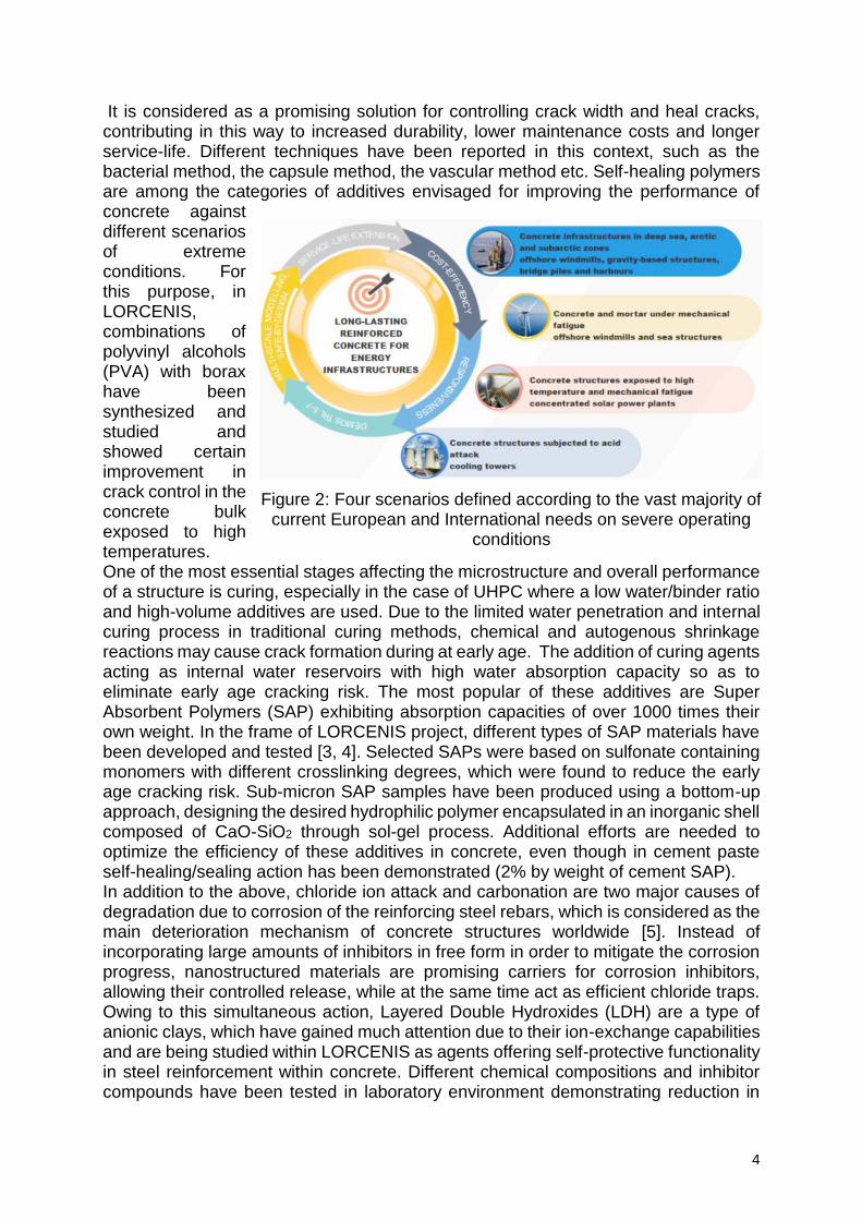
nanoadditives in the manufacturing of concrete structures with significantly improved performance, aims to meet a wide range of requirements for extreme conditions like: low temperature, including artic (offshore wind parks, gravity-based structures, harbours or shelf areas with drift ice), high temperature constructions (CSP: Concentrated Solar Power, coal-fired and nuclear power plants, drilling oil well), structures subjected to high mechanical fatigue (concrete tower, slabs and grouts in windmills and maritime structures) and highly corrosive environments (acid attack in biogas plants and cooling towers; chlorides ingress in deep sea and offshore structures) depending on the location of the energy infrastructures (Figure 2). Through interdisciplinary collaboration between material developers and concrete experts, novel additives and materials with self-responsive functionalities have been successfully incorporated in concrete, resulting in the design and testing of 12 prototypes for validation, ranging from TRL 5 to TRL 7, while the requirements in concrete properties are being optimized of at least remain unaffected. 2. Multifunctional nanostructured materials with self-response ability Concrete structures exhibit a relative low reliability due to unexpected extreme situations causing safety and durability issues in relation to the service environment and structural design. Thus, a self-diagnosis/sensing functionality is desirable in a concrete-based infrastructure in order to detect and monitor its performance and condition in real-time, as proposed for the first time in 1993 [1]. The so-called intrinsic self-sensing concrete (ISSC) for structural health monitoring is based on the incorporation of conductive fillers, such as carbon (CF) or steel fibers, CNT or CNF and metallic powders, which increase its ability to sense strain/stress or damage, while additionally improve its mechanical performance. The main idea is that under deformation or stress the conductive path within the composite is altered, affecting also its electrical properties and sensing behavior. In LORCENIS, the combination of two materials has been utilized, CF and CNT. Multi-walled CNT (MWCNT) are synthesized through catalytic chemical vapor deposition method using acetylene as carbon source and Fe/Al2O3 or Fe/zeolite particles as catalysts. An acid treatment is then employed in order to attach oxygen-containing groups on their surface which promote dispersion, resulting in better mechanical and electrical properties of the composite. A decrease of three orders of magnitude has been observed on the percolation threshold, during the first evaluation of durability response in laboratory conditions, with respect to CNT alone and two orders of magnitude with respect to the CMF (0.28% bmoc), when tested under thermal or mechanical fatigue [2]. In addition to self-sensing concrete, self-healing or self-repairing concrete is another type of smart concrete gaining increased scientific interest. An autonomous self-healing functionality is needed in order to enhance the autogenous self-healing action of concrete due to the inevitable crack formation resulting from chemical shrinkage.
Figure 1: LORCENIS innovative solutions and corresponding self-responsive functionalities in concrete.
4
It is considered as a promising solution for controlling crack width and heal cracks, contributing in this way to increased durability, lower maintenance costs and longer service-life. Different techniques have been reported in this context, such as the bacterial method, the capsule method, the vascular method etc. Self-healing polymers are among the categories of additives envisaged for improving the performance of concrete against different scenarios of extreme conditions. For this purpose, in LORCENIS, combinations of polyvinyl alcohols (PVA) with borax have been synthesized and studied and showed certain improvement in crack control in the concrete bulk exposed to high temperatures. One of the most essential stages affecting the microstructure and overall performance of a structure is curing, especially in the case of UHPC where a low water/binder ratio and high-volume additives are used. Due to the limited water penetration and internal curing process in traditional curing methods, chemical and autogenous shrinkage reactions may cause crack formation during at early age. The addition of curing agents acting as internal water reservoirs with high water absorption capacity so as to eliminate early age cracking risk. The most popular of these additives are Super Absorbent Polymers (SAP) exhibiting absorption capacities of over 1000 times their own weight. In the frame of LORCENIS project, different types of SAP materials have been developed and tested [3, 4]. Selected SAPs were based on sulfonate containing monomers with different crosslinking degrees, which were found to reduce the early age cracking risk. Sub-micron SAP samples have been produced using a bottom-up approach, designing the desired hydrophilic polymer encapsulated in an inorganic shell composed of CaO-SiO2 through sol-gel process. Additional efforts are needed to optimize the efficiency of these additives in concrete, even though in cement paste self-healing/sealing action has been demonstrated (2% by weight of cement SAP). In addition to the above, chloride ion attack and carbonation are two major causes of degradation due to corrosion of the reinforcing steel rebars, which is considered as the main deterioration mechanism of concrete structures worldwide [5]. Instead of incorporating large amounts of inhibitors in free form in order to mitigate the corrosion progress, nanostructured materials are promising carriers for corrosion inhibitors, allowing their controlled release, while at the same time act as efficient chloride traps. Owing to this simultaneous action, Layered Double Hydroxides (LDH) are a type of anionic clays, which have gained much attention due to their ion-exchange capabilities and are being studied within LORCENIS as agents offering self-protective functionality in steel reinforcement within concrete. Different chemical compositions and inhibitor compounds have been tested in laboratory environment demonstrating reduction in
Figure 2: Four scenarios defined according to the vast majority of current European and International needs on severe operating
conditions
5
chloride transport and chloride threshold for corrosion initiation, as well as improved frost resistance. Another type of nanostructured material offering self-protection ability in concrete is polyhedral oligomeric silsesquioxanes (POSS) [2] developed to exhibit either water-repellent or corrosion-inhibitive functionalities. Interestingly, the POSS-based derivatives presented certain beneficial effect in delaying the chloride transport and improved the roughness resistance and leaching in soft water. 3. Conclusion Smart and multifunctional materials signify a continuously emerging field in vast applications, while it is also finding use in the construction industry opening ways to many concepts and ideas for advanced self-responsive concrete. As demonstrated above, the possibilities for introducing new features in traditional construction materials are endless, offering many potential benefits such as improved safety and reliability, and reduction in life-cycle costs. It is believed that the available research results have set the foundation for a revolution in the future cement and concrete industries. In view of a sustainable concrete future, many advances should be made on the synthesis and cost-effective upscaled production of additives in order to promote the establishment of new smart multifunctional cement-based materials which will be durable and easily produced, recyclable and eco-friendly, leading to new functional capabilities in conventional concrete materials and structures and significant impacts on society. Acknowledgements This work is supported by the HORIZON 2020 Collaborative project “LORCENIS” (Long Lasting Reinforced Concrete for Energy Infrastructure under Severe Operating Conditions, Grant agreement no.: 685445). The authors would like to thank UGent, CHEMS, SINTEF, SMT, UAVR, CIDET and SIKA for their collaborated efforts in the frame of WP2 “Development of stable admixture with active internal curing, self-sealing and self-healing properties”. References [1] Chen, P.-W. and D.D.L. Chung, Carbon fiber reinforced concrete for smart
structures capable of non-destructive flaw detection. Smart Materials and Structures, 1993. 2(1): p. 22-30.
[2] Bingham, R.V. and D. Nuttall, EUROCORR 2018: applied science with constant awareness. Corrosion Engineering, Science and Technology, 2019. 54(4): p. 279-285.
[3] De Meyst, L., et al., Parameter Study of Superabsorbent Polymers (SAPs) for Use in Durable Concrete Structures. Materials (Basel), 2019. 12(9).
[4] Kanellopoulou, I., et al., Effect of submicron admixtures on mechanical and self-healing properties of cement-based composites. Fatigue & Fracture of Engineering Materials & Structures, 2019. 42(7): p. 1494-1509.
[5] Penttala, V., 1 - Causes and mechanisms of deterioration in reinforced concrete, in Failure, Distress and Repair of Concrete Structures, N. Delatte, Editor. 2009, Woodhead Publishing. p. 3-31.
6
Effect of reactive MgO expansive agent on Self-healing of Strain Hardening Cement-based Composites Crack
Y. Dai1, P. Zhang1, Y. Qiao1, S. Dong1
1Center for Durability & Sustainability Studies of Shandong Province, Qingdao University of Technology, No. 11 Fushun Road, Qingdao, 266033, [email protected]
Abstract This paper investigates the self-healing of cracks in Strain-Hardening Cement-based Composites (SHCC) after incorporating reactive MgO expansive agent (MEA). Three different reactive MgO expansive agents were added to SHCC, these specimens were preloaded under four-point bend test to induce cracks, and then exposed to four different curing conditions (water fog, tap water, saturated Ca(OH)2 solution). The changes of crack width and shapes were observed by using digital microscope, and water absorption test was also applied to measure the sealing ability of cracks. Test results showed that the curing condition had a great influence on the function of MgO expansive agent. The more sufficient water, the more obvious the effect of MgO on promoting self-healing. However, under the curing condition of sat. Ca(OH)2 solution, the sealing degree of the test group mixed with MgO expansive agent was lower than that of the control group. Compared with the control group, the test group mixed with MgO expansive agent significantly improved the healing speed in the presence of water, and the higher the reactivity, the more obvious the improvement effect. Keywords: Self-healing, MgO expansive agent, Strain Hardening Cement-based Composites (SHCC), Cracks 1. Introduction Strain-hardening Cementitious Composites (SHCC) is a special type of High Performance Fibers Reinforced Concrete featuring multiple microcracks [1-3]. Due to its good crack control ability, fiber bridging effect and secondary hydration effect of mineral admixture, SHCC can achieve better healing effect than traditional cement-based materials [4]. However, there are still some challenges such as the lack of water needed to continue hydration and the shortage of un-hydrated cementitious particles within the crack walls should be addressed. Facing these problems, MgO-type expansive agent can be used to overcome these issues, because of the low water demand of MgO-type expansive agent with the ability of densification of microstructure. This study aims to investigate the effect of different reactive MgO expansive agents on self-healing of SHCC cracks. Specimens after induced cracking were placed in three different curing conditions for preselected durations of time, with the aim of following the process of self-healing. The sealing degree of cracks was then determined and evaluated with respect to the crack width and healing period, and water absorption test was also applied to measure the healing ability of cracks.
2. Materials and methods The composition of the cement-based matrix of the SHCC used in this study was as follows: 550 kg/m3 ordinary Portland cement (Type 42.5), 650 kg/m3 fly ash, 550 kg/m3 fine sand, 301 kg/m3 water, and 2% by volume of PVA (Polyvinyl Alcohol) fibres. Three different reactivity (110s,200s,240s) of MgO expansive agents (MEAs) were prepared, and the higher reactivity of MEA, the more purity of MgO. The amount of each MEA is
7
5% measured with mass of binder weight (PC+FA), as shown in table 1. Here the SHCC-CON is SHCC without MgO expansive agent, and the rest of the mixtures contain MEA with different reactivity as SHCC-MEA group. Specimens with the following dimensions were cast into prism mold: 160mm × 25 mm × 40 mm. After demoulding, the specimens were then stored in standard curing room.
Table 1: Cement mixes with MEA by percentage weight (%)
NO. Cement-based
mixes (%)
MEA
110s 200s 240s
SHCC-CON 100 - - - MEA-110s 100 5 - - MEA-200s 100 - 5 - MEA-240s 100 - - 5
At 28 days, the specimens were removed from the curing room to induce crack by four-
point test. The opening of cracks on the bottom surface (160mm×25mm) of the
specimen were measured by a digital microscope, as shown in Figure 1, and average value of four measurements of each crack represented the crack width. Then cracked specimens were cured under three different environmental condition for self-healing:
a) Storage in standard curing room (water fog);b) Immersion (the bottom surface) in
tap water; c) Immersion (the bottom surface) in saturated Ca(OH)2 solution. Each type of curing condition contains all types of specimens. After 7, 28, 60 and 90 days, the crack width of the tested cracked specimens under different conditions were measured again as described above [3]. Also, the specimens underwent a water absorption test. Before the water absorption test, the specimens were dried in a ventilated oven at 50 for 5 days. After cooling to room temperature, the four side surfaces of the beams were covered with self-adhesive aluminium foil, leaving the bottom and top surfaces open, and the cracked surface (bottom surface) was put in direct contact with water. Then, the absorbed mass of water was determined as a function of time by weighing the specimens after 1, 2, 4, 8, 12, and 24 h.
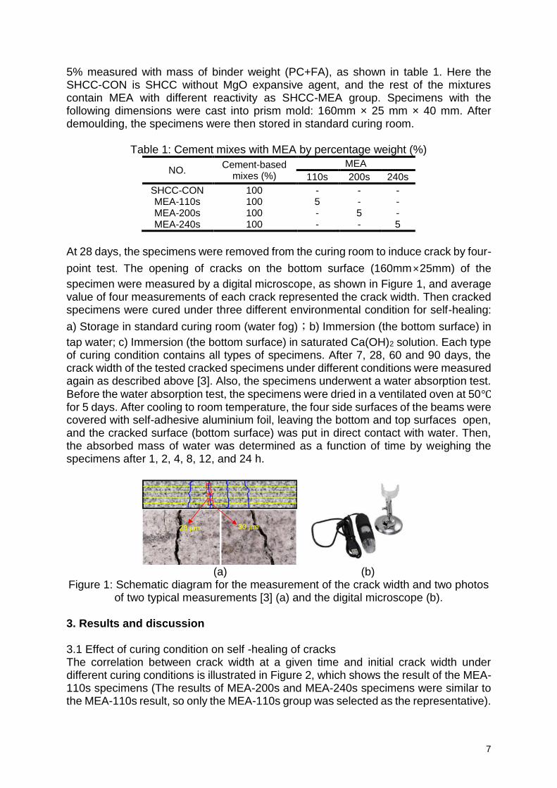
(a) (b) Figure 1: Schematic diagram for the measurement of the crack width and two photos
of two typical measurements [3] (a) and the digital microscope (b). 3. Results and discussion 3.1 Effect of curing condition on self -healing of cracks The correlation between crack width at a given time and initial crack width under different curing conditions is illustrated in Figure 2, which shows the result of the MEA-110s specimens (The results of MEA-200s and MEA-240s specimens were similar to the MEA-110s result, so only the MEA-110s group was selected as the representative).
8
0 20 40 60 80 100
0
20
40
60
80
100
Water fog0d
7d
28d
60d
90d
m=0.3389
m=0.5975
m=0.6850
m=0.7280
Cra
ck w
idth
at g
ive
n t
ime,
m
Initial crack width, m
m=1
0 20 40 60 80 100
0
20
40
60
80
100
Cra
ck w
idth
at giv
en tim
e,
m
Initial crack width, m
m=0.0930
m=0.1639
m=0.2055
m=0.5937
0d
7d
28d
60d
90d
m=1
Tap Water
0 20 40 60 80 100
Initial crack width, m
Sat.Ca(OH)20d
7d
28d
60d
90d
m=0.2975
m=0.4261
m=0.6314
m=0.8766
m=1
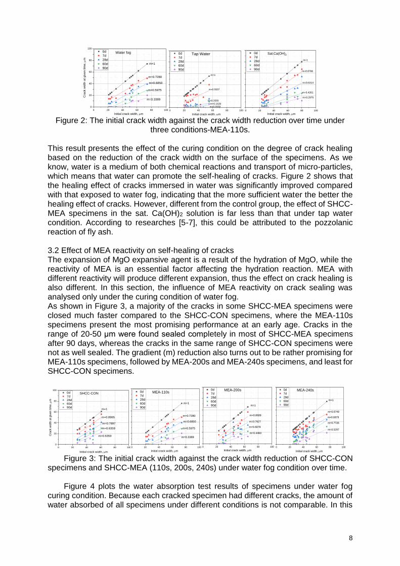
Figure 2: The initial crack width against the crack width reduction over time under
three conditions-MEA-110s. This result presents the effect of the curing condition on the degree of crack healing based on the reduction of the crack width on the surface of the specimens. As we know, water is a medium of both chemical reactions and transport of micro-particles, which means that water can promote the self-healing of cracks. Figure 2 shows that the healing effect of cracks immersed in water was significantly improved compared with that exposed to water fog, indicating that the more sufficient water the better the healing effect of cracks. However, different from the control group, the effect of SHCC-MEA specimens in the sat. Ca(OH)2 solution is far less than that under tap water condition. According to researches [5-7], this could be attributed to the pozzolanic reaction of fly ash. 3.2 Effect of MEA reactivity on self-healing of cracks The expansion of MgO expansive agent is a result of the hydration of MgO, while the reactivity of MEA is an essential factor affecting the hydration reaction. MEA with different reactivity will produce different expansion, thus the effect on crack healing is also different. In this section, the influence of MEA reactivity on crack sealing was analysed only under the curing condition of water fog. As shown in Figure 3, a majority of the cracks in some SHCC-MEA specimens were closed much faster compared to the SHCC-CON specimens, where the MEA-110s specimens present the most promising performance at an early age. Cracks in the range of 20-50 μm were found sealed completely in most of SHCC-MEA specimens after 90 days, whereas the cracks in the same range of SHCC-CON specimens were not as well sealed. The gradient (m) reduction also turns out to be rather promising for MEA-110s specimens, followed by MEA-200s and MEA-240s specimens, and least for SHCC-CON specimens.
0 20 40 60 80 100
0
20
40
60
80
100
m=0.6359
m=0.7897
m=0.6359
m=0.8965
0d
7d
28d
60d
90d
Cra
ck w
idth
at giv
en tim
e,
m
Initial crack width, m
m=1
SHCC-CON
0 20 40 60 80 100
MEA-110s0d
7d
28d
60d
90d
m=0.3389
m=0.5975
m=0.6850
m=0.7280
Initial crack width, m
m=1
0 20 40 60 80 100
Initial crack width, m
m=0.4460
m=0.6878
m=1
m=0.7627
m=0.8689
m=1
MEA-200s0d
7d
28d
60d
90d
0 20 40 60 80 100
MEA-240s0d
7d
28d
60d
90d
m=0.5297
m=0.7726
m=0.6879
m=0.6749
m=1
Initial crack width, m Figure 3: The initial crack width against the crack width reduction of SHCC-CON
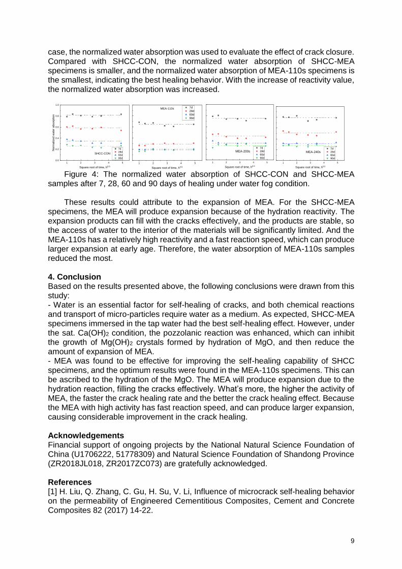
specimens and SHCC-MEA (110s, 200s, 240s) under water fog condition over time. Figure 4 plots the water absorption test results of specimens under water fog
curing condition. Because each cracked specimen had different cracks, the amount of water absorbed of all specimens under different conditions is not comparable. In this
9
case, the normalized water absorption was used to evaluate the effect of crack closure. Compared with SHCC-CON, the normalized water absorption of SHCC-MEA specimens is smaller, and the normalized water absorption of MEA-110s specimens is the smallest, indicating the best healing behavior. With the increase of reactivity value, the normalized water absorption was increased.
1 2 3 4 50.0
0.2
0.4
0.6
0.8
1.0
No
rma
lize
d w
ate
r ab
sorp
tio
n
Square root of time, h0.5
7d
28d
60d
90d
SHCC-CON
1 2 3 4 5
Square root of time, h0.5
7d
28d
60d
90d
MEA-110s
1 2 3 4 5
MEA-200s
Square root of time, h0.5
7d
28d
60d
90d
1 2 3 4 5
MEA-240s
Square root of time, h0.5
7d
28d
60d
90d
Figure 4: The normalized water absorption of SHCC-CON and SHCC-MEA
samples after 7, 28, 60 and 90 days of healing under water fog condition. These results could attribute to the expansion of MEA. For the SHCC-MEA
specimens, the MEA will produce expansion because of the hydration reactivity. The expansion products can fill with the cracks effectively, and the products are stable, so the access of water to the interior of the materials will be significantly limited. And the MEA-110s has a relatively high reactivity and a fast reaction speed, which can produce larger expansion at early age. Therefore, the water absorption of MEA-110s samples reduced the most.
4. Conclusion Based on the results presented above, the following conclusions were drawn from this study: - Water is an essential factor for self-healing of cracks, and both chemical reactions and transport of micro-particles require water as a medium. As expected, SHCC-MEA specimens immersed in the tap water had the best self-healing effect. However, under the sat. Ca(OH)2 condition, the pozzolanic reaction was enhanced, which can inhibit the growth of Mg(OH)2 crystals formed by hydration of MgO, and then reduce the amount of expansion of MEA. - MEA was found to be effective for improving the self-healing capability of SHCC specimens, and the optimum results were found in the MEA-110s specimens. This can be ascribed to the hydration of the MgO. The MEA will produce expansion due to the hydration reaction, filling the cracks effectively. What’s more, the higher the activity of MEA, the faster the crack healing rate and the better the crack healing effect. Because the MEA with high activity has fast reaction speed, and can produce larger expansion, causing considerable improvement in the crack healing.
Acknowledgements Financial support of ongoing projects by the National Natural Science Foundation of China (U1706222, 51778309) and Natural Science Foundation of Shandong Province (ZR2018JL018, ZR2017ZC073) are gratefully acknowledged.
References [1] H. Liu, Q. Zhang, C. Gu, H. Su, V. Li, Influence of microcrack self-healing behavior on the permeability of Engineered Cementitious Composites, Cement and Concrete Composites 82 (2017) 14-22.
10
[2] T.S. Qureshi, A. Altabbaa, Self-healing of drying shrinkage cracks in cement-based materials incorporating reactive MgO, Smart Materials and Structures 25 (2016) 084004. [3] P. Zhang, Y. Dai, X. Ding, C. Zhou, X. Xue, T. Zhao, Self-healing behaviour of multiple microcracks of strain hardening cementitious composites (SHCC), Construction and Building Materials 169 (2018) 705-715. [4] M.A.A. Sherir, K.M.A. Hossain, M. Lachemi, The influence of MgO-type expansive agent incorporated in self-healing system of engineered cementitious composites, Construction and Building Materials 149 (2017) 164-185. [5] L. Mo, M. Deng, M. Tang, A. Al-Tabbaa, MgO expansive cement and concrete in China: Past, present and future, Cement and Concrete Research 57 (2014) 1-12. [6] L. Mo, M. Liu, A. Al-Tabbaa, M. Deng, W.Y. Lau, Deformation and mechanical properties of quaternary blended cements containing ground granulated blast furnace slag, fly ash and magnesia, Cement and Concrete Research 71 (2015) 7-13. [7] V. Kasselouris, C. Ftikos, G. Parissakis, On the hydration of MgO in cement pastes hydrated up to eight years, Cement and Concrete Research 15 (1985) 758-764.
11
Use of alkali-activated cementitious materials as impressed current cathodic protection anodes for long-term structural health
Graeme Jones 1, Paul Lambert 2
1Structural Healthcare Limited, Unit 2 Wharton Street, Sherdley Road Industrial Estate, St Helens, WA9 5AA United Kingdom – email: [email protected] 2Mott MacDonald, Spring Bank House, Stamford Street, Altrincham, Cheshire WA14 1ES United Kingdom – email: [email protected]
Abstract Building structures with resilience (structural health) can be achieved with a multi-component systems approach that combines the use of low carbon alkali-activated cementitious materials (AACMs) with embedded monitoring probes for service life tracking and online monitoring. AACMs are complex alumina-silicates with over 80% CO2e savings compared to OPC that can be used as an alternative to Portland cement (OPC) concrete or in combination with OPC to deliver structures with enhanced fire, chemical and environmental resistantance with inbuilt corrosion control. This paper discusses an application of this material as a conductive impressed current cathodic protection (ICCP) anode mortar or concrete that can provide compliance with EN ISO 12696:2016 without the need for additional anode materials. Keywords: AACM, resilience, corrosion, performance, sustainability
1. Introduction
In 1998 Sir John Egan reported [1] to the UK Government recommending radical change to “rethink construction”, highlighting the importance of information technology (IT) in achieving higher quality and efficiency in construction. At that time technology was emerging in internet control and performance management systems for highways and other sectors [2]. The challenge was therefore issued to embrace IT to provide digital construction, now establishing through BIM, as well as the industrialisation and “componentisation” of offsite construction. This paper discusses the integration of inherently low-carbon smart materials with embedded performance monitoring tools on digital networks to provide management and control for the service life of structures so as to achieve significantly extended service life without the need for costly and disruptive future repairs.
2. Low carbon smart materials
Sustainability in construction and the need to reduce CO2 emissions are impacting the choice of construction methods and materials. Portland cements as used in grouts, mortars and concrete products are key areas to target for full or partial replacement with lower energy and lower carbon alternatives. Alkali-activated cementitious materials (AACM), and the sub-set of geopolymers, show promise as alternatives to OPC for use in product formulations. These alternative binders can deliver equivalent or significantly improved characteristics with respect to strength, adhesion and resistance to fire, chemical and mechanical damage [3,4]. They consist of inorganic cements manufactured predominantly from recycled materials and industrial by-products in ambient (no heat) blended formulations designed to match the required characteristics of the end-product, and yield a saving on carbon emissions compared to Portland cement of up to 80%. When mixed with alkaline activators, these binders,
12
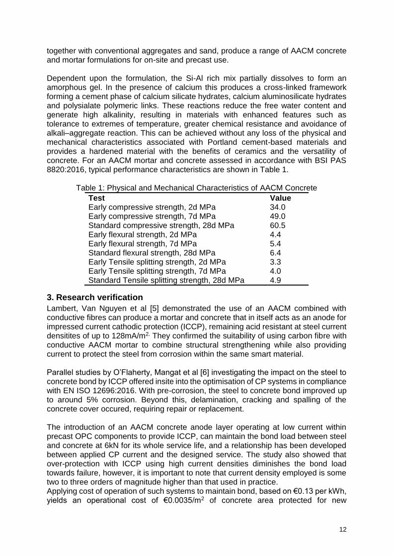
together with conventional aggregates and sand, produce a range of AACM concrete and mortar formulations for on-site and precast use. Dependent upon the formulation, the Si-Al rich mix partially dissolves to form an amorphous gel. In the presence of calcium this produces a cross-linked framework forming a cement phase of calcium silicate hydrates, calcium aluminosilicate hydrates and polysialate polymeric links. These reactions reduce the free water content and generate high alkalinity, resulting in materials with enhanced features such as tolerance to extremes of temperature, greater chemical resistance and avoidance of alkali–aggregate reaction. This can be achieved without any loss of the physical and mechanical characteristics associated with Portland cement-based materials and provides a hardened material with the benefits of ceramics and the versatility of concrete. For an AACM mortar and concrete assessed in accordance with BSI PAS 8820:2016, typical performance characteristics are shown in Table 1.
Table 1: Physical and Mechanical Characteristics of AACM Concrete
Test Value Early compressive strength, 2d MPa 34.0 Early compressive strength, 7d MPa 49.0 Standard compressive strength, 28d MPa 60.5 Early flexural strength, 2d MPa 4.4 Early flexural strength, 7d MPa 5.4 Standard flexural strength, 28d MPa 6.4 Early Tensile splitting strength, 2d MPa 3.3 Early Tensile splitting strength, 7d MPa 4.0 Standard Tensile splitting strength, 28d MPa 4.9
3. Research verification
Lambert, Van Nguyen et al [5] demonstrated the use of an AACM combined with conductive fibres can produce a mortar and concrete that in itself acts as an anode for impressed current cathodic protection (ICCP), remaining acid resistant at steel current densitites of up to 128mA/m2. They confirmed the suitability of using carbon fibre with conductive AACM mortar to combine structural strengthening while also providing current to protect the steel from corrosion within the same smart material. Parallel studies by O’Flaherty, Mangat et al [6] investigating the impact on the steel to concrete bond by ICCP offered insite into the optimisation of CP systems in compliance with EN ISO 12696:2016. With pre-corrosion, the steel to concrete bond improved up to around 5% corrosion. Beyond this, delamination, cracking and spalling of the concrete cover occured, requiring repair or replacement. The introduction of an AACM concrete anode layer operating at low current within precast OPC components to provide ICCP, can maintain the bond load between steel and concrete at 6kN for its whole service life, and a relationship has been developed between applied CP current and the designed service. The study also showed that over-protection with ICCP using high current densities diminishes the bond load towards failure, however, it is important to note that current density employed is some two to three orders of magnitude higher than that used in practice. Applying cost of operation of such systems to maintain bond, based on €0.13 per kWh, yields an operational cost of €0.0035/m2 of concrete area protected for new
13
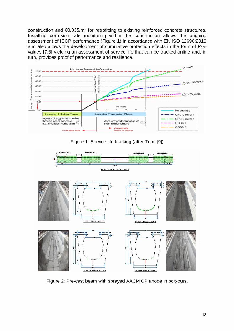
construction and €0.035/m2 for retrofitting to existing reinforced concrete structures. Installing corrosion rate monitoring within the construction allows the ongoing assessment of ICCP performance (Figure 1) in accordance with EN ISO 12696:2016 and also allows the development of cumulative protection effects in the form of Pcorr values [7,8] yielding an assessment of service life that can be tracked online and, in turn, provides proof of performance and resilience.
Figure 1: Service life tracking (after Tuuti [9])
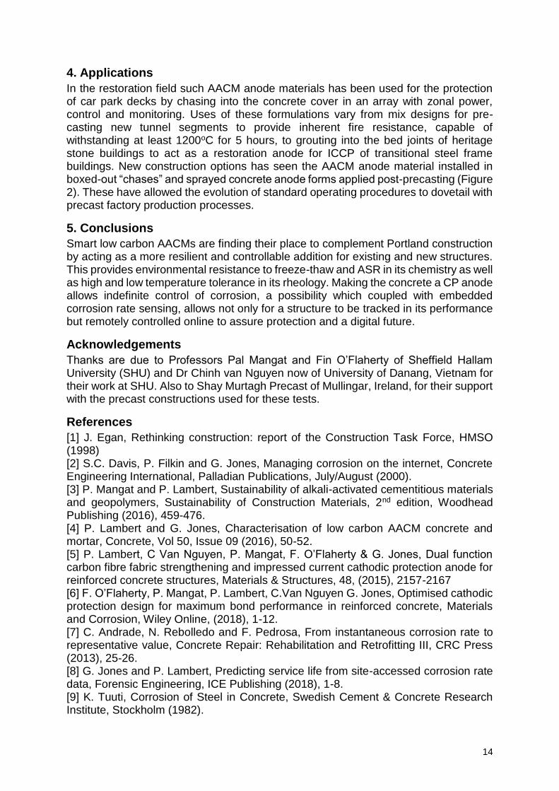
Figure 2: Pre-cast beam with sprayed AACM CP anode in box-outs.
14
4. Applications
In the restoration field such AACM anode materials has been used for the protection of car park decks by chasing into the concrete cover in an array with zonal power, control and monitoring. Uses of these formulations vary from mix designs for pre-casting new tunnel segments to provide inherent fire resistance, capable of withstanding at least 1200oC for 5 hours, to grouting into the bed joints of heritage stone buildings to act as a restoration anode for ICCP of transitional steel frame buildings. New construction options has seen the AACM anode material installed in boxed-out “chases” and sprayed concrete anode forms applied post-precasting (Figure 2). These have allowed the evolution of standard operating procedures to dovetail with precast factory production processes.
5. Conclusions
Smart low carbon AACMs are finding their place to complement Portland construction by acting as a more resilient and controllable addition for existing and new structures. This provides environmental resistance to freeze-thaw and ASR in its chemistry as well as high and low temperature tolerance in its rheology. Making the concrete a CP anode allows indefinite control of corrosion, a possibility which coupled with embedded corrosion rate sensing, allows not only for a structure to be tracked in its performance but remotely controlled online to assure protection and a digital future.
Acknowledgements
Thanks are due to Professors Pal Mangat and Fin O’Flaherty of Sheffield Hallam University (SHU) and Dr Chinh van Nguyen now of University of Danang, Vietnam for their work at SHU. Also to Shay Murtagh Precast of Mullingar, Ireland, for their support with the precast constructions used for these tests.
References
[1] J. Egan, Rethinking construction: report of the Construction Task Force, HMSO (1998) [2] S.C. Davis, P. Filkin and G. Jones, Managing corrosion on the internet, Concrete Engineering International, Palladian Publications, July/August (2000). [3] P. Mangat and P. Lambert, Sustainability of alkali-activated cementitious materials and geopolymers, Sustainability of Construction Materials, 2nd edition, Woodhead Publishing (2016), 459-476. [4] P. Lambert and G. Jones, Characterisation of low carbon AACM concrete and mortar, Concrete, Vol 50, Issue 09 (2016), 50-52. [5] P. Lambert, C Van Nguyen, P. Mangat, F. O’Flaherty & G. Jones, Dual function carbon fibre fabric strengthening and impressed current cathodic protection anode for reinforced concrete structures, Materials & Structures, 48, (2015), 2157-2167 [6] F. O’Flaherty, P. Mangat, P. Lambert, C.Van Nguyen G. Jones, Optimised cathodic protection design for maximum bond performance in reinforced concrete, Materials and Corrosion, Wiley Online, (2018), 1-12. [7] C. Andrade, N. Rebolledo and F. Pedrosa, From instantaneous corrosion rate to representative value, Concrete Repair: Rehabilitation and Retrofitting III, CRC Press (2013), 25-26. [8] G. Jones and P. Lambert, Predicting service life from site-accessed corrosion rate data, Forensic Engineering, ICE Publishing (2018), 1-8. [9] K. Tuuti, Corrosion of Steel in Concrete, Swedish Cement & Concrete Research Institute, Stockholm (1982).
15
The development of SAPs for reducing autogenous shrinkage and accomplishing self-healing and self-sealing properties in concrete
Els Mannekens1, Geert Deroover1
1 ChemStream bvba, Drie Eikenstraat 661, 2650 Edegem, Belgium – email: els.mannekens@ chemstream.be; [email protected]
Abstract Super absorbing polymers (SAPs) are widely studied in concrete as additives to mitigate autogenous shrinkage and to add self-healing and self-sealing properties to the concrete. [1] When buying commercial SAPs, one is usually stuck to a specific SAP chemistry, to defined particle sizes and in many cases to huge swelling degrees of the SAP particles. We think however that different parameters like the type of chemistry, the crosslinking degree or the swelling potential and the particle size of the SAP powders are crucial for optimizing the SAP-admixture for each type of concrete. ChemStream performed the bulk synthesis of a specific type of SAP that was crosslinked in different degrees and that was further dried and grinded to a variety of particle sizes in order to be tested in concrete. Keywords: super absorbing polymer, bulk polymerization, crosslinking, particle size distribution, concrete additive 1. Introduction Commercial available SAPs are usually powders containing a specific chemistry, particle size distribution (PSD) and swelling capacity in water. Most of the commercial SAPs are built from the monomers acrylic acid (AA), partially neutralized to its salt or carboxylate form (-COO-M+), and acrylamide (AAm).[2] They are only slightly crosslinked in order to have huge swelling properties up to 300-400 g demineralized water / g SAP, because they are produced to be used in sanitary and convenience products. When these commercial SAPs are tested as additives in concrete mixes, it is hard to relate the results to the effect of the chemistry, to the influence of the particle size or to the crosslinking degree or swelling capacity of these products. In the LORCENIS project we wanted to understand better which SAP parameters are influencing which concrete characteristics. Therefore, ChemStream synthesized a variation of SAPs, based on a different type of chemistry, having various crosslinking degrees (and thus water swelling capacities) and grinded them to different particle size distributions ranging from 20 to 500 um in diameter. At ChemStream experience was built up in the past on the formulation of UV-curable hydrogel formulations that deliver a water-absorbing coating after application on a substrate and subsequent curing by UV-light.[3] The chemistry used in this application is not based on carboxylate chemistry as mentioned above, but on sulfonate chemistry. Sulfonic acids are much stronger acids than carboxylic acids and they lead to much higher osmotic forces for attracting the water into the formed hydrogel networks. Additionally they are less influenced by changes in the pH of their environment.
16
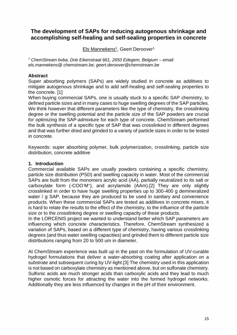
Figure 1: Schematic representation of a SAP particle containing a dens network of
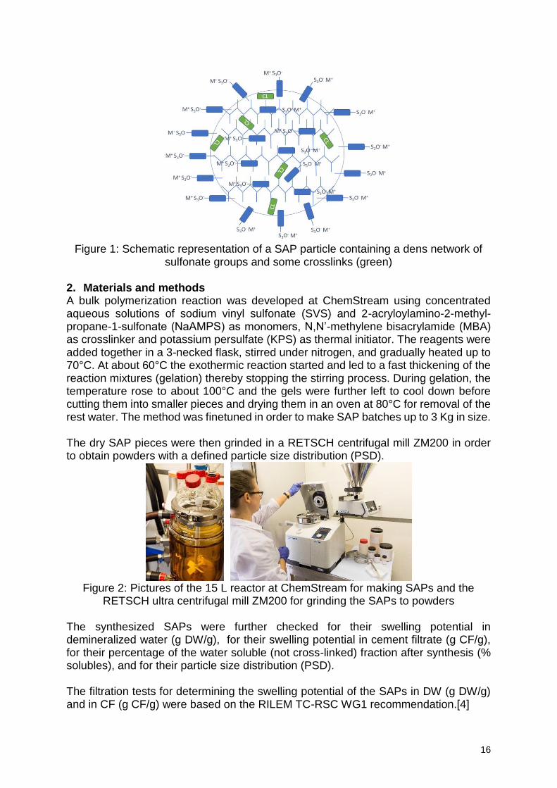
sulfonate groups and some crosslinks (green) 2. Materials and methods A bulk polymerization reaction was developed at ChemStream using concentrated aqueous solutions of sodium vinyl sulfonate (SVS) and 2-acryloylamino-2-methyl-propane-1-sulfonate (NaAMPS) as monomers, N,N’-methylene bisacrylamide (MBA) as crosslinker and potassium persulfate (KPS) as thermal initiator. The reagents were added together in a 3-necked flask, stirred under nitrogen, and gradually heated up to 70°C. At about 60°C the exothermic reaction started and led to a fast thickening of the reaction mixtures (gelation) thereby stopping the stirring process. During gelation, the temperature rose to about 100°C and the gels were further left to cool down before cutting them into smaller pieces and drying them in an oven at 80°C for removal of the rest water. The method was finetuned in order to make SAP batches up to 3 Kg in size. The dry SAP pieces were then grinded in a RETSCH centrifugal mill ZM200 in order to obtain powders with a defined particle size distribution (PSD).
Figure 2: Pictures of the 15 L reactor at ChemStream for making SAPs and the
RETSCH ultra centrifugal mill ZM200 for grinding the SAPs to powders The synthesized SAPs were further checked for their swelling potential in demineralized water (g DW/g), for their swelling potential in cement filtrate (g CF/g), for their percentage of the water soluble (not cross-linked) fraction after synthesis (% solubles), and for their particle size distribution (PSD).
The filtration tests for determining the swelling potential of the SAPs in DW (g DW/g) and in CF (g CF/g) were based on the RILEM TC-RSC WG1 recommendation.[4]
17
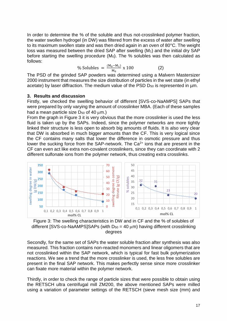
In order to determine the % of the soluble and thus not-crosslinked polymer fraction, the water swollen hydrogel (in DW) was filtered from the excess of water after swelling to its maximum swollen state and was then dried again in an oven of 80°C. The weight loss was measured between the dried SAP after swelling (M1) and the initial dry SAP before starting the swelling procedure (M0). The % solubles was then calculated as follows:
% Solubles = (M0−M1)
M0 x 100 (2)
The PSD of the grinded SAP powders was determined using a Malvern Mastersizer 2000 instrument that measures the size distribution of particles in the wet state (in ethyl acetate) by laser diffraction. The medium value of the PSD D50 is represented in µm. 3. Results and discussion Firstly, we checked the swelling behavior of different [SVS-co-NaAMPS] SAPs that were prepared by only varying the amount of crosslinker MBA. (Each of these samples
had a mean particle size D50 of 40 m.) From the graph in Figure 3 it is very obvious that the more crosslinker is used the less fluid is taken up by the SAPs. Indeed, since the polymer networks are more tightly linked their structure is less open to absorb big amounts of fluids. It is also very clear that DW is absorbed in much bigger amounts than the CF. This is very logical since the CF contains many salts that lower the difference in osmotic pressure and thus lower the sucking force from the SAP-network. The Ca2+ ions that are present in the CF can even act like extra non-covalent crosslinkers, since they can coordinate with 2 different sulfonate ions from the polymer network, thus creating extra crosslinks.
Figure 3: The swelling characteristics in DW and in CF and the % of solubles of
different [SVS-co-NaAMPS]SAPs (with D50 = 40 m) having different crosslinking degrees
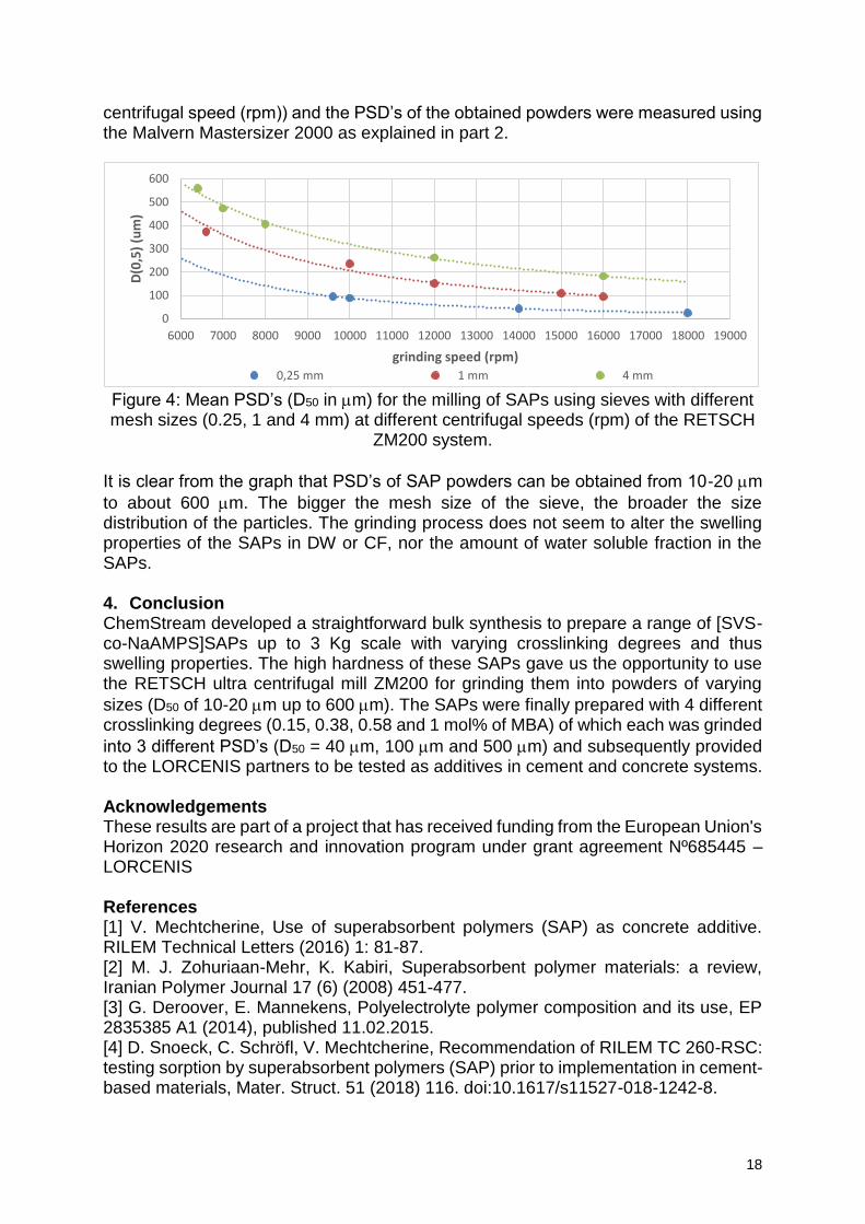
Secondly, for the same set of SAPs the water soluble fraction after synthesis was also measured. This fraction contains non-reacted monomers and linear oligomers that are not crosslinked within the SAP network, which is typical for fast bulk polymerization reactions. We see a trend that the more crosslinker is used, the less free solubles are present in the final SAP network. This makes perfectly sense since more crosslinker can fixate more material within the polymer network. Thirdly, in order to check the range of particle sizes that were possible to obtain using the RETSCH ultra centrifugal mill ZM200, the above mentioned SAPs were milled using a variation of parameter settings of the RETSCH (sieve mesh size (mm) and
0
10
20
30
40
50
60
70
50
100
150
200
250
300
350
0,1 0,2 0,3 0,4 0,5 0,6 0,7 0,8 0,9 1
swel
ling
deg
ree
in c
emen
t fi
ltra
te (
g C
F/g)
swel
ling
deg
ree
in w
ater
(g
DW
/g)
mol% CL
32 31
2320
15
20
25
30
35
40
45
50
0,1 0,2 0,3 0,4 0,5 0,6 0,7 0,8 0,9 1
% s
olu
ble
s
mol% CL
18
centrifugal speed (rpm)) and the PSD’s of the obtained powders were measured using the Malvern Mastersizer 2000 as explained in part 2.
Figure 4: Mean PSD’s (D50 in m) for the milling of SAPs using sieves with different mesh sizes (0.25, 1 and 4 mm) at different centrifugal speeds (rpm) of the RETSCH
ZM200 system.
It is clear from the graph that PSD’s of SAP powders can be obtained from 10-20 m
to about 600 m. The bigger the mesh size of the sieve, the broader the size distribution of the particles. The grinding process does not seem to alter the swelling properties of the SAPs in DW or CF, nor the amount of water soluble fraction in the SAPs. 4. Conclusion ChemStream developed a straightforward bulk synthesis to prepare a range of [SVS-co-NaAMPS]SAPs up to 3 Kg scale with varying crosslinking degrees and thus swelling properties. The high hardness of these SAPs gave us the opportunity to use the RETSCH ultra centrifugal mill ZM200 for grinding them into powders of varying
sizes (D50 of 10-20 m up to 600 m). The SAPs were finally prepared with 4 different crosslinking degrees (0.15, 0.38, 0.58 and 1 mol% of MBA) of which each was grinded
into 3 different PSD’s (D50 = 40 m, 100 m and 500 m) and subsequently provided to the LORCENIS partners to be tested as additives in cement and concrete systems. Acknowledgements These results are part of a project that has received funding from the European Union's Horizon 2020 research and innovation program under grant agreement Nº685445 – LORCENIS References [1] V. Mechtcherine, Use of superabsorbent polymers (SAP) as concrete additive. RILEM Technical Letters (2016) 1: 81-87. [2] M. J. Zohuriaan-Mehr, K. Kabiri, Superabsorbent polymer materials: a review, Iranian Polymer Journal 17 (6) (2008) 451-477. [3] G. Deroover, E. Mannekens, Polyelectrolyte polymer composition and its use, EP 2835385 A1 (2014), published 11.02.2015. [4] D. Snoeck, C. Schröfl, V. Mechtcherine, Recommendation of RILEM TC 260-RSC: testing sorption by superabsorbent polymers (SAP) prior to implementation in cement-based materials, Mater. Struct. 51 (2018) 116. doi:10.1617/s11527-018-1242-8.
0
100
200
300
400
500
600
6000 7000 8000 9000 10000 11000 12000 13000 14000 15000 16000 17000 18000 19000
D(0
,5)
(um
)
grinding speed (rpm)
0,25 mm 1 mm 4 mm
19
The Development of Mini-Vascular Networks for Self-Healing Concrete
C. De Nardi1, D. Gardner1, A. Jefferson1, T Selverajoo1, G. Evans1
1 Resilient Materials for Life Research Team, School of Engineering, Cardiff University, Queen’s Buildings, Newport Road, CF24 3AA, Cardiff, UK - e-mail: [email protected]; [email protected]; [email protected]; [email protected]; [email protected]
Abstract Akin to vascular networks carrying clotting agents in the human body, vascular networks in concrete deliver liquid healing agents to areas of damage [1]. Connection to an external supply of healing agent allows for an unlimited volume of damage to be repaired on a reoccurring basis. Vascular networks in concrete have assumed many forms and have been created using a variety of materials and techniques. Early studies used long thin glass channels embedded within concrete, whilst recent studies have focused on networks formed using 3D printed polymers and hollow channels formed by the removal of shrinkable polymers [2]. The most significant obstacle preventing wide-scale use of vascular networks in concrete remains the challenge associated with the manufacture and placement of the network during the concrete casting stage. Recent work has focused on overcoming this challenge though the development of mini-vascular networks (MVNs), which allow for more complex arrangements of channels in both two and three dimensions and for ready inclusion during the concrete mixing stage.
This paper presents the development of MVNs which assume the form of 3D tetrahedral units (TETs) with hollow ligaments, manufactured from Polylactic Acid (PLA) using 3D printing techniques. The optimisation of the dimensions, surface topography and disposition of the units is considered, alongside their material properties and response to damage events. A range of healing agents, including cyanoacrylates (PC) and sodium silicate (SS) have been explored, with initial results demonstrating the importance of healing agent selection when considering the temporal and spatial scale of the target damage. Further tests have explored the potential to achieve multiple healing events, with promising results. Future refinement of the MVNs includes the formation of dual hollow channels for bi-component healing agents, and adaption of the form of the MVN for a range of structural applications.
Keywords: Self-healing; Mini Vascular Networks, Healing Agents 1. Introduction The inspiration for the development of vascular networks for self-healing cementitious systems is drawn from the arterial system of the human body. The vascular network has several advantages over closed systems, such as being able to supply different healing agents, at different times and being able to continually supply healing agents to the damage location [3]. There is also the potential, in the most intelligent of cases, and nature of the material forming the network, to deliver damage prevention agents in an “immunology” response. However, the advent of a full scale and constructable vascular network for cementitious materials is yet to be realised. Research to date has focussed on the material used for the network, such as glass, ceramics or printed
20
polymers [4], and the form of the network [2,4]. One, two and three dimensional systems have been established, however, the compatibility of these systems to large scale applications is still limited to only 2 studies [5,6].
In order to overcome the challenges concerned with construction, attention has been directed towards mini-vascular networks (MVNs). These MVNs can be filled with a range of healing agents and are readily deployable within a concrete mix without incurring any additional concrete manufacture time. The aim of this study is to identify the optimum form of the MVN, including ligament dimensions, wall thickness, surface profile and distribution within the mix.
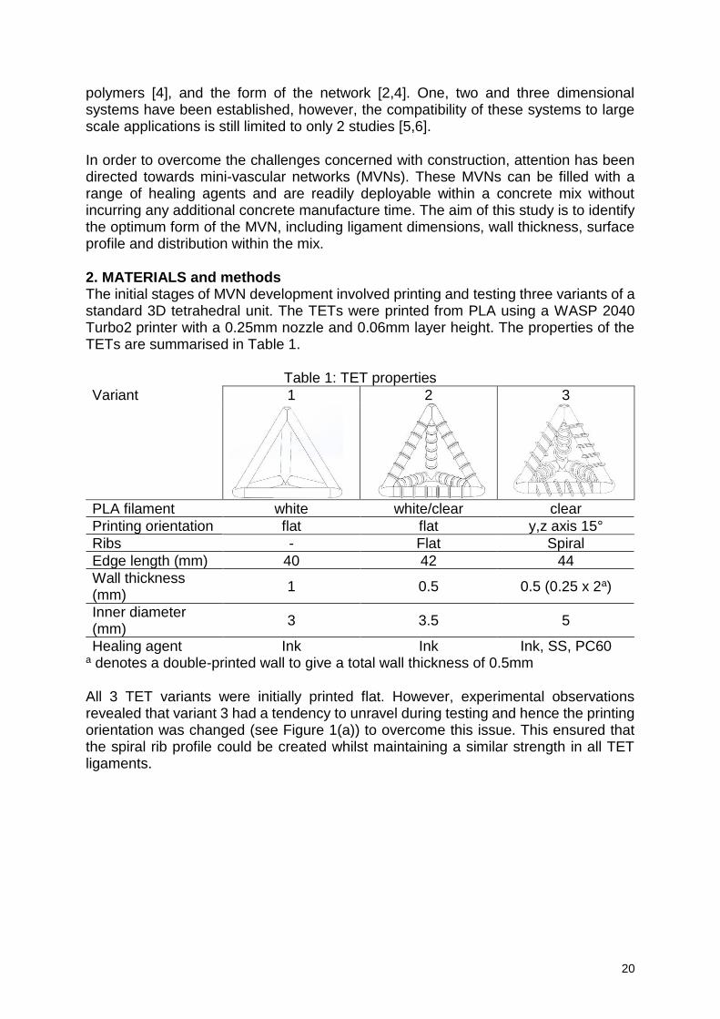
2. MATERIALS and methods The initial stages of MVN development involved printing and testing three variants of a standard 3D tetrahedral unit. The TETs were printed from PLA using a WASP 2040 Turbo2 printer with a 0.25mm nozzle and 0.06mm layer height. The properties of the TETs are summarised in Table 1.
Table 1: TET properties
Variant 1 2 3
PLA filament white white/clear clear
Printing orientation flat flat y,z axis 15°
Ribs - Flat Spiral
Edge length (mm) 40 42 44
Wall thickness (mm)
1 0.5 0.5 (0.25 x 2a)
Inner diameter (mm)
3 3.5 5
Healing agent Ink Ink Ink, SS, PC60 a denotes a double-printed wall to give a total wall thickness of 0.5mm
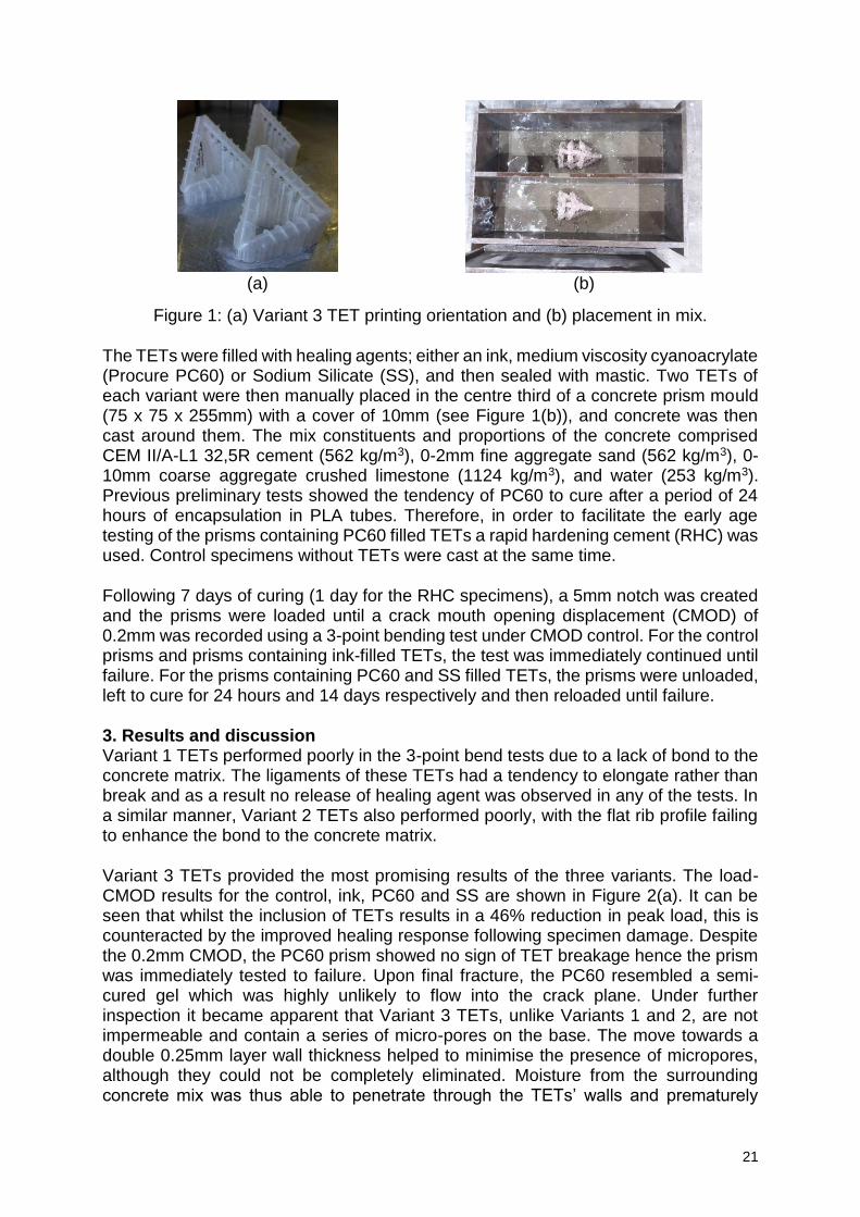
All 3 TET variants were initially printed flat. However, experimental observations revealed that variant 3 had a tendency to unravel during testing and hence the printing orientation was changed (see Figure 1(a)) to overcome this issue. This ensured that the spiral rib profile could be created whilst maintaining a similar strength in all TET ligaments.
21
(a) (b)
Figure 1: (a) Variant 3 TET printing orientation and (b) placement in mix.
The TETs were filled with healing agents; either an ink, medium viscosity cyanoacrylate (Procure PC60) or Sodium Silicate (SS), and then sealed with mastic. Two TETs of each variant were then manually placed in the centre third of a concrete prism mould (75 x 75 x 255mm) with a cover of 10mm (see Figure 1(b)), and concrete was then cast around them. The mix constituents and proportions of the concrete comprised CEM II/A-L1 32,5R cement (562 kg/m3), 0-2mm fine aggregate sand (562 kg/m3), 0-10mm coarse aggregate crushed limestone (1124 kg/m3), and water (253 kg/m3). Previous preliminary tests showed the tendency of PC60 to cure after a period of 24 hours of encapsulation in PLA tubes. Therefore, in order to facilitate the early age testing of the prisms containing PC60 filled TETs a rapid hardening cement (RHC) was used. Control specimens without TETs were cast at the same time.
Following 7 days of curing (1 day for the RHC specimens), a 5mm notch was created and the prisms were loaded until a crack mouth opening displacement (CMOD) of 0.2mm was recorded using a 3-point bending test under CMOD control. For the control prisms and prisms containing ink-filled TETs, the test was immediately continued until failure. For the prisms containing PC60 and SS filled TETs, the prisms were unloaded, left to cure for 24 hours and 14 days respectively and then reloaded until failure.
3. Results and discussion Variant 1 TETs performed poorly in the 3-point bend tests due to a lack of bond to the concrete matrix. The ligaments of these TETs had a tendency to elongate rather than break and as a result no release of healing agent was observed in any of the tests. In a similar manner, Variant 2 TETs also performed poorly, with the flat rib profile failing to enhance the bond to the concrete matrix.
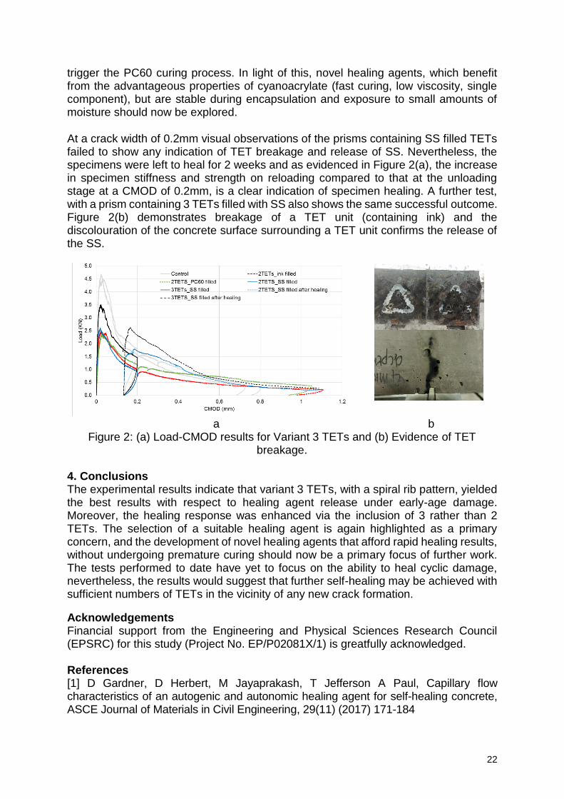
Variant 3 TETs provided the most promising results of the three variants. The load-CMOD results for the control, ink, PC60 and SS are shown in Figure 2(a). It can be seen that whilst the inclusion of TETs results in a 46% reduction in peak load, this is counteracted by the improved healing response following specimen damage. Despite the 0.2mm CMOD, the PC60 prism showed no sign of TET breakage hence the prism was immediately tested to failure. Upon final fracture, the PC60 resembled a semi-cured gel which was highly unlikely to flow into the crack plane. Under further inspection it became apparent that Variant 3 TETs, unlike Variants 1 and 2, are not impermeable and contain a series of micro-pores on the base. The move towards a double 0.25mm layer wall thickness helped to minimise the presence of micropores, although they could not be completely eliminated. Moisture from the surrounding concrete mix was thus able to penetrate through the TETs’ walls and prematurely
22
trigger the PC60 curing process. In light of this, novel healing agents, which benefit from the advantageous properties of cyanoacrylate (fast curing, low viscosity, single component), but are stable during encapsulation and exposure to small amounts of moisture should now be explored.
At a crack width of 0.2mm visual observations of the prisms containing SS filled TETs failed to show any indication of TET breakage and release of SS. Nevertheless, the specimens were left to heal for 2 weeks and as evidenced in Figure 2(a), the increase in specimen stiffness and strength on reloading compared to that at the unloading stage at a CMOD of 0.2mm, is a clear indication of specimen healing. A further test, with a prism containing 3 TETs filled with SS also shows the same successful outcome. Figure 2(b) demonstrates breakage of a TET unit (containing ink) and the discolouration of the concrete surface surrounding a TET unit confirms the release of the SS.
a b Figure 2: (a) Load-CMOD results for Variant 3 TETs and (b) Evidence of TET
breakage. 4. Conclusions The experimental results indicate that variant 3 TETs, with a spiral rib pattern, yielded the best results with respect to healing agent release under early-age damage. Moreover, the healing response was enhanced via the inclusion of 3 rather than 2 TETs. The selection of a suitable healing agent is again highlighted as a primary concern, and the development of novel healing agents that afford rapid healing results, without undergoing premature curing should now be a primary focus of further work. The tests performed to date have yet to focus on the ability to heal cyclic damage, nevertheless, the results would suggest that further self-healing may be achieved with sufficient numbers of TETs in the vicinity of any new crack formation.
Acknowledgements Financial support from the Engineering and Physical Sciences Research Council (EPSRC) for this study (Project No. EP/P02081X/1) is greatfully acknowledged. References [1] D Gardner, D Herbert, M Jayaprakash, T Jefferson A Paul, Capillary flow characteristics of an autogenic and autonomic healing agent for self-healing concrete, ASCE Journal of Materials in Civil Engineering, 29(11) (2017) 171-184
23
[2] R Davies, A Jefferson, R Lark D Gardner, A novel 2D vascular network in cementitious materials. fib Symposium 2015, Copenhagen, Denmark, 2015. [3] B Blaiszik, S Kramer, S Olugebefola, J Moore, N Sottos, S White, 2010. Self-Healing Polymers and Composites. Annual Review of Materials Research 40, 179–211. [4] N De Belie et al. A Review of Self-Healing Concrete for Damage Management of Structures. Advanced Materials Interfaces (2018) [5] C Dry, Repair and prevention of damage due to transverse shrinkage cracks in bridge decks. Smart Structures and Materials 3671 (1999) [6] R Davies, O Teall, M Pilegis, A Kanellopoulos, T Sharma, A Jefferson, D Gardner, A Al-Tabbaa, K Paine, R Lark, Large Scale Application of Self-Healing Concrete: Design, Construction, and Testing. Frontiers in Materials (2018)
24
Textile-reinforced concrete to realise ultra high durability concrete (UHDC) in the framework of the EU H2020 project “ReSHEALience”
C. Schröfl1, A. Peled2, O. Regev2, R. P. Borg3, M. Reichardt1, R. Sripada2,
V. Mechtcherine1, P. Deegan4, L. Ferrara5
1 Technische Universität Dresden, Institute of Construction Materials, Georg-Schumann-Strasse 7, 01187 Dresden, Germany – [email protected]; [email protected]; [email protected] 2 Ben Gurion University of the Negev, Beer Sheva, 84105 Israel – [email protected]; [email protected]; [email protected] 3 University of Malta, Faculty for the Built Environment, Tal-Qroqq, MSD 2080 Msida, Malta – [email protected] 4 Banagher Precast Ltd., Queen Street 11, Banagher Offaly, Ireland – [email protected] 5 Politecnico di Milano, Piazza Leonardo da Vinci 32, 20133 Milano, Italy – [email protected]
Abstract The EU H2020 project “ReSHEALience” (rethinking coastal defence and green-energy service infrastructures through enhanced-durability high-performance cement-based materials) focuses on a holistic approach to create ultra-high durability concrete (UHDC) encompassing the concept and development of advanced materials and tailored design approaches to provide innovative structural solutions. One kind of cement-based composites to realise UHDC structures is textile-reinforced concrete (TRC), in which multiple layers of carbon multifilament yarns composed to a fabric serve as the reinforcement. TRC exhibits multiple micro-crack formation upon tensile loading with fairly small individual crack opening widths, below about 100 µm under service conditions. This characteristic in conjunction with functional admixtures is expected to reach a pronounced self-healing propensity of the cement-based matrix even under very harsh XS exposure conditions. Subsequent to durability-related laboratory experiments regarding sea water as the aggressive medium, two real-scale demonstration projects will be implemented, specifically a breakwater on the Irish west coast and the restoration of a historic water reservoir tower in Malta. This paper presents the concept of TRC development towards a UHDC, outlines the characteristics of the two demonstrators and some preliminary laboratory results. Keywords: Carbon multifilament; multiple micro-crack formation; self-healing; textile-reinforced concrete (TRC); ultra high durability concrete (UHDC) 1. Introduction The EU H2020 project “ReSHEALience” (rethinking coastal defence and green-energy service infrastructures through enhanced-durability high-performance cement-based materials) advances from high-performance concretes (HPC) with superior mechanical performance to designing most durable civil engineering structures made out of cement-based composites. Starting at the material level of matrix composition and reinforcement design, general objectives include quantification and prediction of the durability of both laboratory-scale specimens and real-scale pilot structures subjected to extremely aggressive exposures. Infrastructures encompassing durability problems include, among others, coastal defence and off-shore civil works (XS, exposure to sea water) and facilities serving geothermal energy plants (XA, chemical attack). Carbon-textile reinforced concrete (TRC) is considered for two demonstration structures in XS:
25
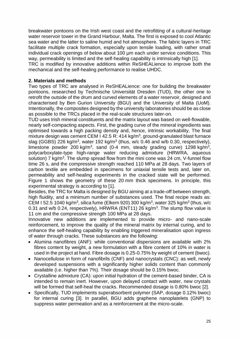
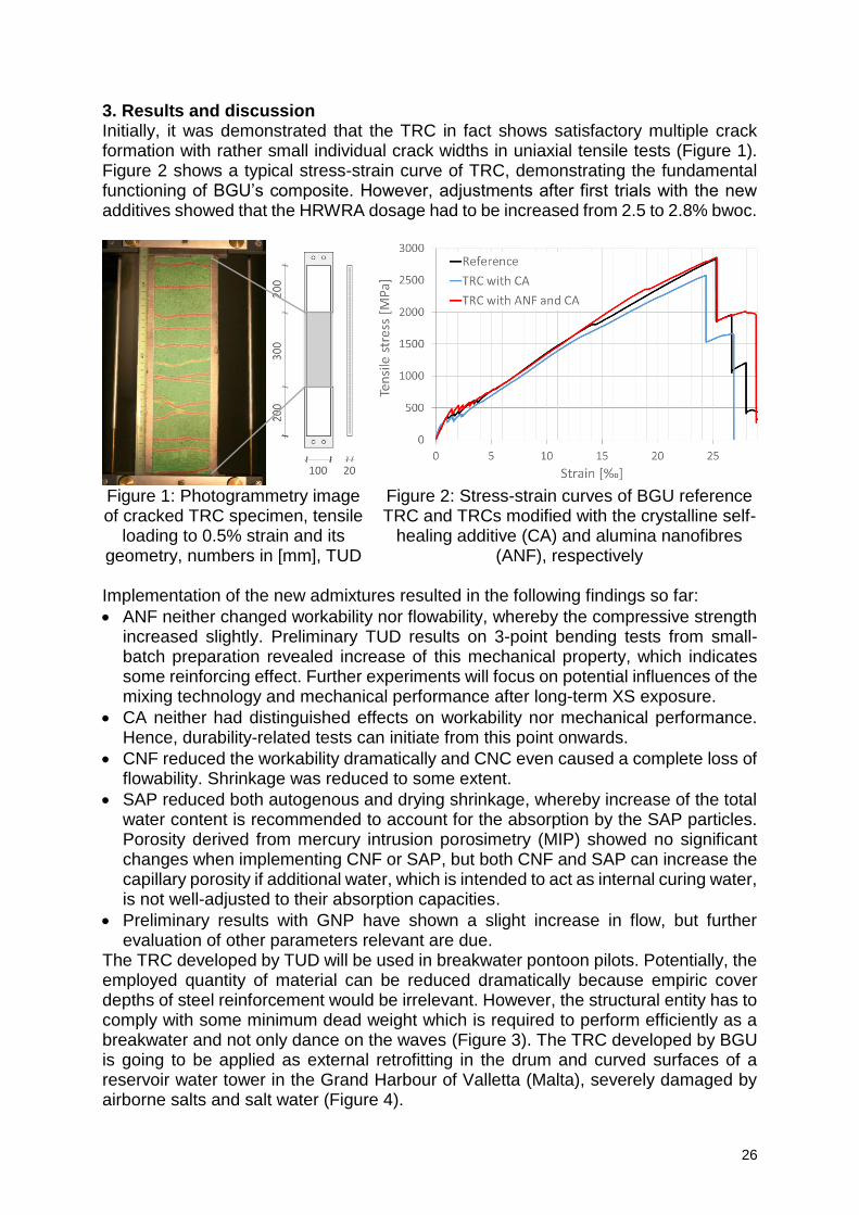
breakwater pontoons on the Irish west coast and the retrofitting of a cultural-heritage water reservoir tower in the Grand Harbour, Malta. The first is exposed to cool Atlantic sea water and the latter to saline humid and hot atmosphere. The fabric layers in TRC facilitate multiple crack formation, especially upon tensile loading, with rather small individual crack openings of below about 100 µm each under service conditions. This way, permeability is limited and the self-healing capability is intrinsically high [1]. TRC is modified by innovative additions within ReSHEALience to improve both the mechanical and the self-healing performance to realise UHDC. 2. Materials and methods Two types of TRC are analysed in ReSHEALience: one for building the breakwater pontoons, researched by Technische Universität Dresden (TUD), the other one to retrofit the outside of the drum and curved elements of a water reservoir, designed and characterised by Ben Gurion University (BGU) and the University of Malta (UoM). Intentionally, the composites designed by the university laboratories should be as close as possible to the TRCs placed in the real-scale structures later-on. TUD uses Irish mineral constituents and the matrix layout was based on well-flowable, nearly self-compacting aspects. First, the grading curve of the mineral ingredients was optimised towards a high packing density and, hence, intrinsic workability. The final mixture design was cement CEM I 42.5 R: 414 kg/m3, ground-granulated blast furnace slag (GGBS) 226 kg/m3, water 192 kg/m3 (thus, w/c 0.46 and w/b 0.30, respectively), limestone powder 200 kg/m3, sand (0-4 mm, steady grading curve) 1298 kg/m3, polycarboxylate-type high-range water reducing admixture (HRWRA, aqueous solution) 7 kg/m3. The slump spread flow from the mini cone was 24 cm, V-funnel flow time 26 s, and the compressive strength reached 110 MPa at 28 days. Two layers of carbon textile are embedded in specimens for uniaxial tensile tests and, later on, permeability and self-healing experiments in the cracked state will be performed. Figure 1 shows the geometry of these 20 mm thick specimens. In principle, this experimental strategy is according to [1]. Besides, the TRC for Malta is designed by BGU aiming at a trade-off between strength, high fluidity, and a minimum number of substances used. The final recipe reads as: CEM I 52.5 1040 kg/m3, silica fume (Elkem 920) 300 kg/m3, water 325 kg/m3 (thus, w/c 0.31 and w/b 0.24, respectively), HRWRA (ENT11) 26 kg/m3. The slump flow value is 11 cm and the compressive strength 100 MPa at 28 days. Innovative new additions are implemented to provide micro- and nano-scale reinforcement, to improve the quality of the mineral matrix by internal curing, and to enhance the self-healing capability by enabling triggered mineralisation upon ingress of water through cracks. These substances are the following:
Alumina nanofibres (ANF): while conventional dispersions are available with 2% fibres content by weight, a new formulation with a fibre content of 10% in water is used in the project at hand. Fibre dosage is 0.25-0.75% by weight of cement (bwoc).
Nanocellulose in form of nanofibrils (CNF) and nanocrystals (CNC): as well, newly developed suspensions with a significantly higher solids content than commonly available (i.e. higher than 7%). Their dosage should be 0.15% bwoc.
Crystalline admixture (CA): upon initial hydration of the cement-based binder, CA is intended to remain inert. However, upon delayed contact with water, new crystals will be formed that self-heal the cracks. Recommended dosage is 0.80% bwoc [2].
Specifically, TUD implements superabsorbent polymer (SAP, dosage 0.12% bwoc) for internal curing [3]. In parallel, BGU adds graphene nanoplatelets (GNP) to suppress water permeation and as a reinforcement at the micro-scale.
26
3. Results and discussion Initially, it was demonstrated that the TRC in fact shows satisfactory multiple crack formation with rather small individual crack widths in uniaxial tensile tests (Figure 1). Figure 2 shows a typical stress-strain curve of TRC, demonstrating the fundamental functioning of BGU’s composite. However, adjustments after first trials with the new additives showed that the HRWRA dosage had to be increased from 2.5 to 2.8% bwoc.
Figure 1: Photogrammetry image of cracked TRC specimen, tensile
loading to 0.5% strain and its geometry, numbers in [mm], TUD
Figure 2: Stress-strain curves of BGU reference TRC and TRCs modified with the crystalline self-
healing additive (CA) and alumina nanofibres (ANF), respectively
Implementation of the new admixtures resulted in the following findings so far:
ANF neither changed workability nor flowability, whereby the compressive strength increased slightly. Preliminary TUD results on 3-point bending tests from small-batch preparation revealed increase of this mechanical property, which indicates some reinforcing effect. Further experiments will focus on potential influences of the mixing technology and mechanical performance after long-term XS exposure.
CA neither had distinguished effects on workability nor mechanical performance. Hence, durability-related tests can initiate from this point onwards.
CNF reduced the workability dramatically and CNC even caused a complete loss of flowability. Shrinkage was reduced to some extent.
SAP reduced both autogenous and drying shrinkage, whereby increase of the total water content is recommended to account for the absorption by the SAP particles. Porosity derived from mercury intrusion porosimetry (MIP) showed no significant changes when implementing CNF or SAP, but both CNF and SAP can increase the capillary porosity if additional water, which is intended to act as internal curing water, is not well-adjusted to their absorption capacities.
Preliminary results with GNP have shown a slight increase in flow, but further evaluation of other parameters relevant are due.
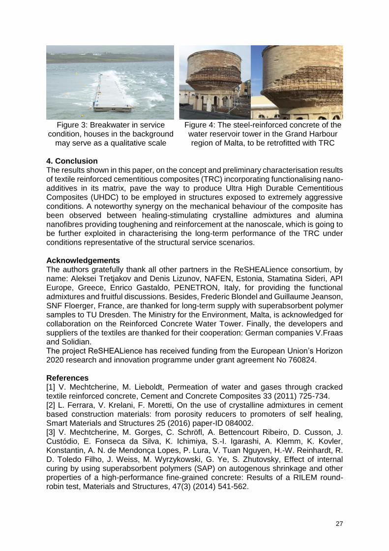
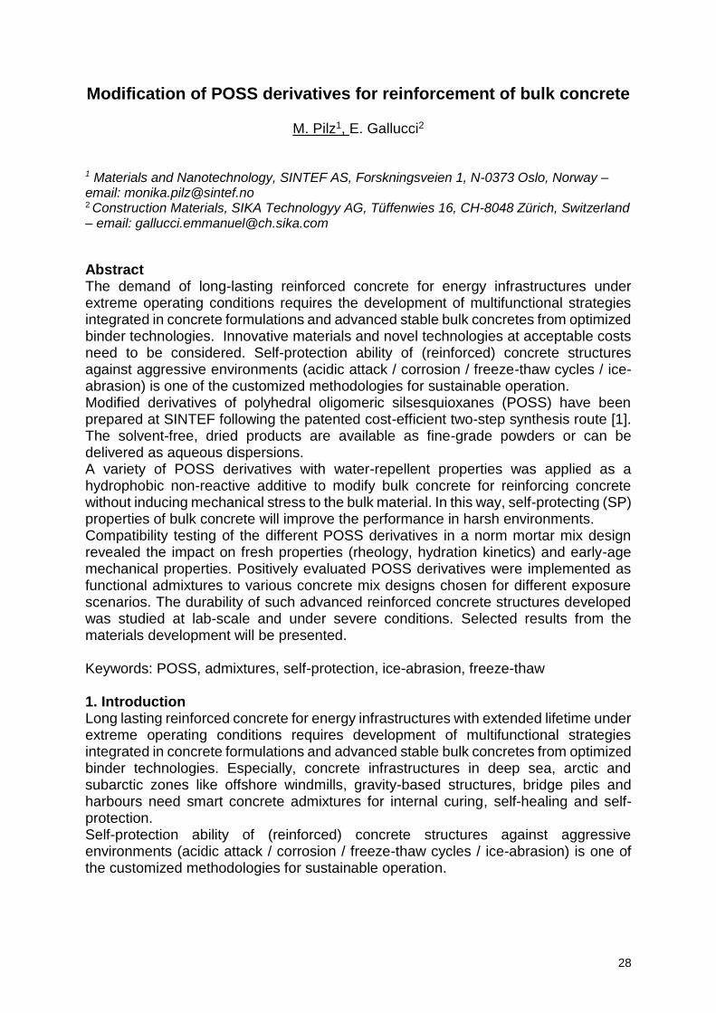
The TRC developed by TUD will be used in breakwater pontoon pilots. Potentially, the employed quantity of material can be reduced dramatically because empiric cover depths of steel reinforcement would be irrelevant. However, the structural entity has to comply with some minimum dead weight which is required to perform efficiently as a breakwater and not only dance on the waves (Figure 3). The TRC developed by BGU is going to be applied as external retrofitting in the drum and curved surfaces of a reservoir water tower in the Grand Harbour of Valletta (Malta), severely damaged by airborne salts and salt water (Figure 4).
27
Figure 3: Breakwater in service
condition, houses in the background may serve as a qualitative scale
Figure 4: The steel-reinforced concrete of the water reservoir tower in the Grand Harbour region of Malta, to be retrofitted with TRC
4. Conclusion The results shown in this paper, on the concept and preliminary characterisation results of textile reinforced cementitious composites (TRC) incorporating functionalising nano-additives in its matrix, pave the way to produce Ultra High Durable Cementitious Composites (UHDC) to be employed in structures exposed to extremely aggressive conditions. A noteworthy synergy on the mechanical behaviour of the composite has been observed between healing-stimulating crystalline admixtures and alumina nanofibres providing toughening and reinforcement at the nanoscale, which is going to be further exploited in characterising the long-term performance of the TRC under conditions representative of the structural service scenarios. Acknowledgements The authors gratefully thank all other partners in the ReSHEALience consortium, by name: Aleksei Tretjakov and Denis Lizunov, NAFEN, Estonia, Stamatina Sideri, API Europe, Greece, Enrico Gastaldo, PENETRON, Italy, for providing the functional admixtures and fruitful discussions. Besides, Frederic Blondel and Guillaume Jeanson, SNF Floerger, France, are thanked for long-term supply with superabsorbent polymer samples to TU Dresden. The Ministry for the Environment, Malta, is acknowledged for collaboration on the Reinforced Concrete Water Tower. Finally, the developers and suppliers of the textiles are thanked for their cooperation: German companies V.Fraas and Solidian. The project ReSHEALience has received funding from the European Union’s Horizon 2020 research and innovation programme under grant agreement No 760824. References [1] V. Mechtcherine, M. Lieboldt, Permeation of water and gases through cracked textile reinforced concrete, Cement and Concrete Composites 33 (2011) 725-734. [2] L. Ferrara, V. Krelani, F. Moretti, On the use of crystalline admixtures in cement based construction materials: from porosity reducers to promoters of self healing, Smart Materials and Structures 25 (2016) paper-ID 084002. [3] V. Mechtcherine, M. Gorges, C. Schröfl, A. Bettencourt Ribeiro, D. Cusson, J. Custódio, E. Fonseca da Silva, K. Ichimiya, S.-I. Igarashi, A. Klemm, K. Kovler, Konstantin, A. N. de Mendonça Lopes, P. Lura, V. Tuan Nguyen, H.-W. Reinhardt, R. D. Toledo Filho, J. Weiss, M. Wyrzykowski, G. Ye, S. Zhutovsky, Effect of internal curing by using superabsorbent polymers (SAP) on autogenous shrinkage and other properties of a high-performance fine-grained concrete: Results of a RILEM round-robin test, Materials and Structures, 47(3) (2014) 541-562.
28
Modification of POSS derivatives for reinforcement of bulk concrete
M. Pilz1, E. Gallucci2
1 Materials and Nanotechnology, SINTEF AS, Forskningsveien 1, N-0373 Oslo, Norway – email: [email protected] 2 Construction Materials, SIKA Technologyy AG, Tüffenwies 16, CH-8048 Zürich, Switzerland – email: [email protected]
Abstract The demand of long-lasting reinforced concrete for energy infrastructures under extreme operating conditions requires the development of multifunctional strategies integrated in concrete formulations and advanced stable bulk concretes from optimized binder technologies. Innovative materials and novel technologies at acceptable costs need to be considered. Self-protection ability of (reinforced) concrete structures against aggressive environments (acidic attack / corrosion / freeze-thaw cycles / ice-abrasion) is one of the customized methodologies for sustainable operation. Modified derivatives of polyhedral oligomeric silsesquioxanes (POSS) have been prepared at SINTEF following the patented cost-efficient two-step synthesis route [1]. The solvent-free, dried products are available as fine-grade powders or can be delivered as aqueous dispersions. A variety of POSS derivatives with water-repellent properties was applied as a hydrophobic non-reactive additive to modify bulk concrete for reinforcing concrete without inducing mechanical stress to the bulk material. In this way, self-protecting (SP) properties of bulk concrete will improve the performance in harsh environments. Compatibility testing of the different POSS derivatives in a norm mortar mix design revealed the impact on fresh properties (rheology, hydration kinetics) and early-age mechanical properties. Positively evaluated POSS derivatives were implemented as functional admixtures to various concrete mix designs chosen for different exposure scenarios. The durability of such advanced reinforced concrete structures developed was studied at lab-scale and under severe conditions. Selected results from the materials development will be presented. Keywords: POSS, admixtures, self-protection, ice-abrasion, freeze-thaw 1. Introduction Long lasting reinforced concrete for energy infrastructures with extended lifetime under extreme operating conditions requires development of multifunctional strategies integrated in concrete formulations and advanced stable bulk concretes from optimized binder technologies. Especially, concrete infrastructures in deep sea, arctic and subarctic zones like offshore windmills, gravity-based structures, bridge piles and harbours need smart concrete admixtures for internal curing, self-healing and self-protection. Self-protection ability of (reinforced) concrete structures against aggressive environments (acidic attack / corrosion / freeze-thaw cycles / ice-abrasion) is one of the customized methodologies for sustainable operation.
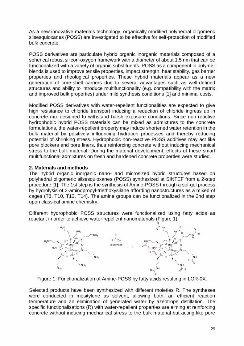
29
As a new innovative materials technology, organically modified polyhedral oligomeric silsesquioxanes (POSS) are investigated to be effective for self-protection of modified bulk concrete. POSS derivatives are particulate hybrid organic inorganic materials composed of a spherical robust silicon-oxygen framework with a diameter of about 1.5 nm that can be functionalized with a variety of organic substituents. POSS as a component in polymer blends is used to improve tensile properties, impact strength, heat stability, gas barrier properties and rheological properties. These hybrid materials appear as a new generation of core-shell carriers due to several advantages such as well-defined structures and ability to introduce multifunctionality (e.g. compatibility with the matrix and improved bulk properties) under mild synthesis conditions [1] and minimal costs. Modified POSS derivatives with water-repellent functionalities are expected to give high resistance to chloride transport inducing a reduction of chloride ingress up in concrete mix designed to withstand harsh exposure conditions. Since non-reactive hydrophobic hybrid POSS materials can be mixed as admixtures to the concrete formulations, the water-repellent property may induce shortened water retention in the bulk material by positively influencing hydration processes and thereby reducing potential of shrinking stress. Hydrophobic non-reactive POSS additives may act like pore blockers and pore liners, thus reinforcing concrete without inducing mechanical stress to the bulk material. During the material development, effects of these smart multifunctional admixtures on fresh and hardened concrete properties were studied. 2. Materials and methods The hybrid organic inorganic nano- and microsized hybrid structures based on polyhedral oligomeric silsesquioxanes (POSS) synthesized at SINTEF from a 2-step procedure [1]. The 1st step is the synthesis of Amine-POSS through a sol-gel process by hydrolysis of 3-aminopropyl-triethoxysilane affording nanostructures as a mixed of cages (T8, T10, T12, T14). The amine groups can be functionalized in the 2nd step upon classical amine chemistry. Different hydrophobic POSS structures were functionalized using fatty acids as reactant in order to achieve water repellent nanomaterials (Figure 1).
Figure 1: Functionalization of Amine-POSS by fatty acids resulting in LOR-0X.
Selected products have been synthesized with different moieties R. The syntheses were conducted in mesitylene as solvent, allowing both, an efficient reaction temperature and an elimination of generated water by azeotrope distillation. The specific functionalisations (R) with water-repellent properties are aiming at reinforcing concrete without inducing mechanical stress to the bulk material but acting like pore
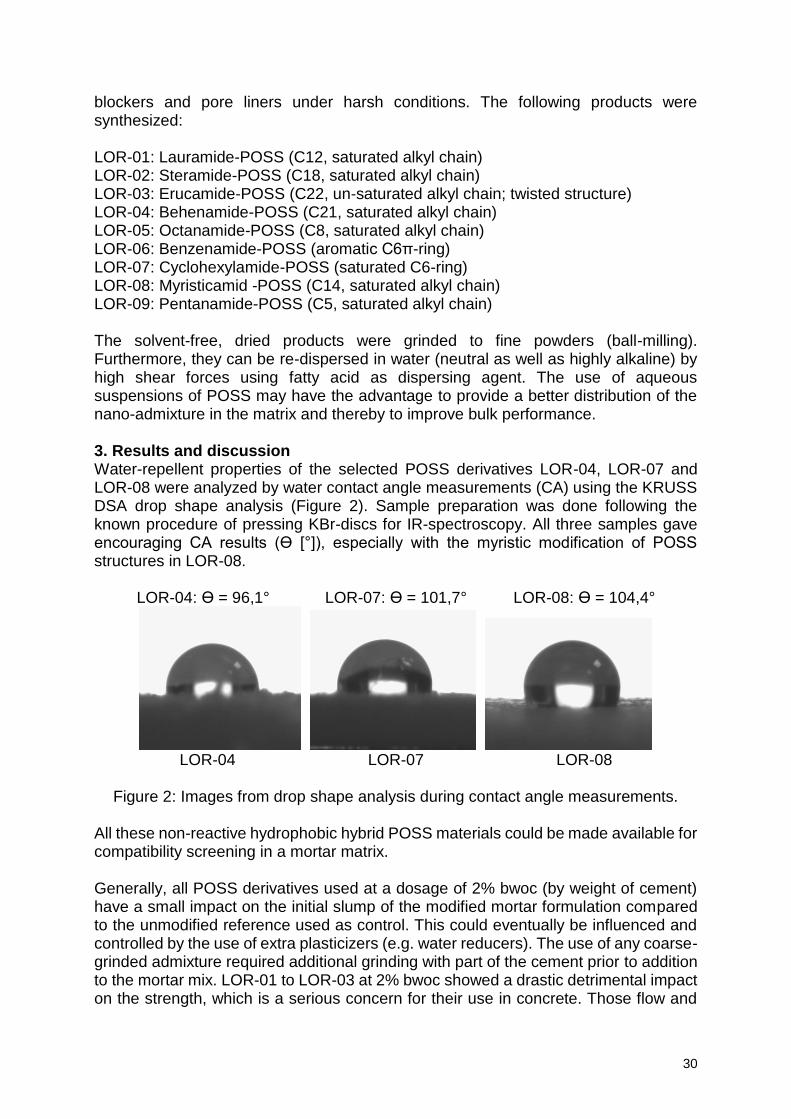
30
blockers and pore liners under harsh conditions. The following products were synthesized: LOR-01: Lauramide-POSS (C12, saturated alkyl chain) LOR-02: Steramide-POSS (C18, saturated alkyl chain) LOR-03: Erucamide-POSS (C22, un-saturated alkyl chain; twisted structure) LOR-04: Behenamide-POSS (C21, saturated alkyl chain) LOR-05: Octanamide-POSS (C8, saturated alkyl chain) LOR-06: Benzenamide-POSS (aromatic C6π-ring) LOR-07: Cyclohexylamide-POSS (saturated C6-ring) LOR-08: Myristicamid -POSS (C14, saturated alkyl chain) LOR-09: Pentanamide-POSS (C5, saturated alkyl chain) The solvent-free, dried products were grinded to fine powders (ball-milling). Furthermore, they can be re-dispersed in water (neutral as well as highly alkaline) by high shear forces using fatty acid as dispersing agent. The use of aqueous suspensions of POSS may have the advantage to provide a better distribution of the nano-admixture in the matrix and thereby to improve bulk performance. 3. Results and discussion Water-repellent properties of the selected POSS derivatives LOR-04, LOR-07 and LOR-08 were analyzed by water contact angle measurements (CA) using the KRUSS DSA drop shape analysis (Figure 2). Sample preparation was done following the known procedure of pressing KBr-discs for IR-spectroscopy. All three samples gave encouraging CA results (Ɵ [°]), especially with the myristic modification of POSS structures in LOR-08.
LOR-04: Ɵ = 96,1° LOR-07: Ɵ = 101,7° LOR-08: Ɵ = 104,4°
LOR-04 LOR-07 LOR-08
Figure 2: Images from drop shape analysis during contact angle measurements.
All these non-reactive hydrophobic hybrid POSS materials could be made available for compatibility screening in a mortar matrix. Generally, all POSS derivatives used at a dosage of 2% bwoc (by weight of cement) have a small impact on the initial slump of the modified mortar formulation compared to the unmodified reference used as control. This could eventually be influenced and controlled by the use of extra plasticizers (e.g. water reducers). The use of any coarse-grinded admixture required additional grinding with part of the cement prior to addition to the mortar mix. LOR-01 to LOR-03 at 2% bwoc showed a drastic detrimental impact on the strength, which is a serious concern for their use in concrete. Those flow and
31
strength issues could be potentially worked out using a decreased dosage. The fine-grinded products (LOR-04 to LOR-09) seem to impact slightly the hydration kinetics, probably because of their higher grade of fineness combined with higher surface area and interface able to interact with the cement binder while LOR06 surprisingly shows a huge delay: more than 24hrs and a strong bleeding of the mortar. Mechanical properties (compressive strength testing at 1d and 7d hardening) are not changed for mortars containing LOR-04 (2% bwoc). For LOR-7 in the range of 2 - 1.5% bwoc and LOR-08 (1.5 – 2% bwoc) reduction in mechanical properties (flexural strength) and in rheology (initial flow slightly low) seems still be acceptable. 4. Conclusion The objective of this compatibility testing was to evaluate whether modified POSS derivatives can be introduced as additives in different concrete mix designs without any too strong detrimental impact on the fresh and hardening properties of those. Impact on the rheology, hydration kinetics and mechanical properties of concrete were evaluated during screening that is not connected with any insight on the performance of the additives. LOR-04 demonstrates a total compatibility on all aspects, LOR-07 seems a good alternative while LOR-06 does not qualify. LOR-04 has been upscaled at SINTEF and has been made available in several kg for preparation of larger concrete specimens in LORCENIS for performance tests in different protocols following the specific scenarios. Water-repellent POSS derivatives are especially assigned for tests in the concrete mix designs developed for scenarios attributed to high chloride ingress [2], freeze thaw conditions [3] and ice abrasion [4]. Acknowledgements This work was supported by the HORIZON 2020 Collaborative project “LORCENIS” (Long Lasting Reinforced Concrete for Energy Infrastructure under Severe Operating Conditions”, Grant agreement nº 685445). References [1] F. Männle, F., C. Simon, C., J. Beylich, J., K. Redford, K., Polybranched, organic/inorganic hybrid polymer and method for its manufacture, US7960492 B2 (2011). [2] P. Lundqvist, The effect of POSS and SAP additives on self-healing of cracks in concrete for hydropower applications, Proceedings of Conference on Durable Concrete for Infrastructure under Severe Conditions, Ghent, 2019. [3] M. Cruz Alonso, K. Villar Arribas, Durability of concrete under combined action of leaching and freeze-thaw processes, Proceedings of Conference on Durable Concrete for Infrastructure under Severe Conditions, Ghent, 2019. [4] A. Baba Ahmadi, Ice abrasion resistance in high performance concrete engineered with new admixtures, Proceedings of Conference on Durable Concrete for Infrastructure under Severe Conditions, Ghent, 2019.
32
The use of self-healing sodium silicate microcapsules in oil well cement under high-temperature wellbore environment
Wenting Mao1, Chrysoula Litina1, Abir Al-Tabbaa1
1 Department of Engineering, University of Cambridge, Trumpington street, Cambridge, CB2 1PZ, United Kingdom. [email protected]; [email protected], [email protected],uk
Abstract The annular cement sheath plays a crucial role in ensuring well integrity by providing adequate zonal isolation, stabilizing the formation, and protecting the casing from corrosion. A majority of well integrity problems originate from cracks of oil well cement. Self-healing materials which have the capability for autonomous crack repair are an attractive solution for addressing durability issues under the severe exposure service conditions of oil well cement. This study proposes the use of sodium silicate microcapsules (with polyurea shell) to improve the self-healing properties of oil well cement. The microcapsules were first tested on the thermal stability and survivability during mixing. The results confirmed their suitability for use under the high-temperature (80oC) in the wellbore. The microcapsules were added into the Class G oil well cement pastes at different contents varying from 0 to 7.5% by weight of cement. The effects of microcapsules on the self-healing performance of oil well cement at 80oC were evaluated through water sorptivity and gas permeability measurements. It was found that oil well cement itself showed very little healing capability when cured at 80oC, but the addition of microcapsules significantly promoted its self-healing performance. After healing for 7 days at 80oC, the microcapsule-containing cement pastes showed a reduction up to ~76% in water sorptivity coefficient and ~ 45% in gas permeability coefficient when compared to the blank cement pastes without microcapsules. In addition, the effects of microcapsules on the hydration of oil well cement pastes were also tested. Keywords: Oil well cement, sodium silicate microcapsules, high temperature. 1. Introduction Cementing is one of the most important and crucial operations performed on oil and gas wells [1]. It delivers zonal isolation, completely sealing off oil and gas from the wellbore, preventing fluid communication between producing zones in the borehole, and blocking the escape of fluids to the surface. The cement barrier plays a key role in well’s operational safety. The properties of cement-based materials are key factors to cementing performance. Conventional oil well cement systems exhibit unfavourable characteristics that adversely affect their sealing capacity such as their brittle nature, shrinkage, and weak bonding to the casing and formation. A majority of well integrity problems originate from cement shrinkage, deformation, and cracking induced by shrinkage strains and stress concentrations imposed by external restraints [2-4]. The cracks and flaws in the cement sheath create pathways for the migration of gas/oil fluids, further leading to gas/oil leakage. Moreover, well cementing exposes cement to conditions far different from those
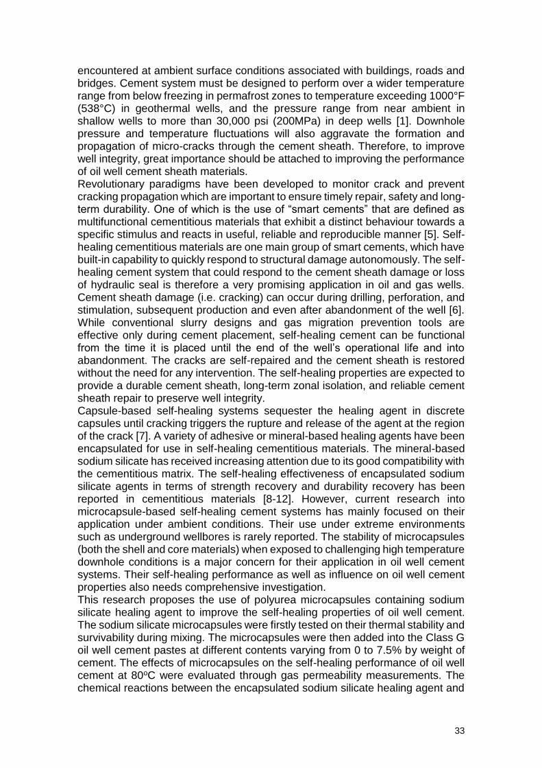
33
encountered at ambient surface conditions associated with buildings, roads and bridges. Cement system must be designed to perform over a wider temperature range from below freezing in permafrost zones to temperature exceeding 1000°F (538°C) in geothermal wells, and the pressure range from near ambient in shallow wells to more than 30,000 psi (200MPa) in deep wells [1]. Downhole pressure and temperature fluctuations will also aggravate the formation and propagation of micro-cracks through the cement sheath. Therefore, to improve well integrity, great importance should be attached to improving the performance of oil well cement sheath materials. Revolutionary paradigms have been developed to monitor crack and prevent cracking propagation which are important to ensure timely repair, safety and long-term durability. One of which is the use of “smart cements” that are defined as multifunctional cementitious materials that exhibit a distinct behaviour towards a specific stimulus and reacts in useful, reliable and reproducible manner [5]. Self-healing cementitious materials are one main group of smart cements, which have built-in capability to quickly respond to structural damage autonomously. The self-healing cement system that could respond to the cement sheath damage or loss of hydraulic seal is therefore a very promising application in oil and gas wells. Cement sheath damage (i.e. cracking) can occur during drilling, perforation, and stimulation, subsequent production and even after abandonment of the well [6]. While conventional slurry designs and gas migration prevention tools are effective only during cement placement, self-healing cement can be functional from the time it is placed until the end of the well’s operational life and into abandonment. The cracks are self-repaired and the cement sheath is restored without the need for any intervention. The self-healing properties are expected to provide a durable cement sheath, long-term zonal isolation, and reliable cement sheath repair to preserve well integrity. Capsule-based self-healing systems sequester the healing agent in discrete capsules until cracking triggers the rupture and release of the agent at the region of the crack [7]. A variety of adhesive or mineral-based healing agents have been encapsulated for use in self-healing cementitious materials. The mineral-based sodium silicate has received increasing attention due to its good compatibility with the cementitious matrix. The self-healing effectiveness of encapsulated sodium silicate agents in terms of strength recovery and durability recovery has been reported in cementitious materials [8-12]. However, current research into microcapsule-based self-healing cement systems has mainly focused on their application under ambient conditions. Their use under extreme environments such as underground wellbores is rarely reported. The stability of microcapsules (both the shell and core materials) when exposed to challenging high temperature downhole conditions is a major concern for their application in oil well cement systems. Their self-healing performance as well as influence on oil well cement properties also needs comprehensive investigation. This research proposes the use of polyurea microcapsules containing sodium silicate healing agent to improve the self-healing properties of oil well cement. The sodium silicate microcapsules were firstly tested on their thermal stability and survivability during mixing. The microcapsules were then added into the Class G oil well cement pastes at different contents varying from 0 to 7.5% by weight of cement. The effects of microcapsules on the self-healing performance of oil well cement at 80oC were evaluated through gas permeability measurements. The chemical reactions between the encapsulated sodium silicate healing agent and
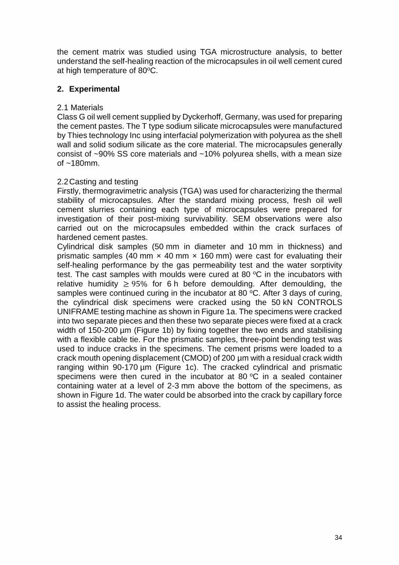
34
the cement matrix was studied using TGA microstructure analysis, to better understand the self-healing reaction of the microcapsules in oil well cement cured at high temperature of 80oC. 2. Experimental 2.1 Materials Class G oil well cement supplied by Dyckerhoff, Germany, was used for preparing the cement pastes. The T type sodium silicate microcapsules were manufactured by Thies technology Inc using interfacial polymerization with polyurea as the shell wall and solid sodium silicate as the core material. The microcapsules generally consist of ~90% SS core materials and ~10% polyurea shells, with a mean size of ~180mm. 2.2 Casting and testing Firstly, thermogravimetric analysis (TGA) was used for characterizing the thermal stability of microcapsules. After the standard mixing process, fresh oil well cement slurries containing each type of microcapsules were prepared for investigation of their post-mixing survivability. SEM observations were also carried out on the microcapsules embedded within the crack surfaces of hardened cement pastes. Cylindrical disk samples (50 mm in diameter and 10 mm in thickness) and prismatic samples (40 mm × 40 mm × 160 mm) were cast for evaluating their self-healing performance by the gas permeability test and the water sorptivity test. The cast samples with moulds were cured at 80 oC in the incubators with relative humidity ≥ 95% for 6 h before demoulding. After demoulding, the samples were continued curing in the incubator at 80 oC. After 3 days of curing, the cylindrical disk specimens were cracked using the 50 kN CONTROLS UNIFRAME testing machine as shown in Figure 1a. The specimens were cracked into two separate pieces and then these two separate pieces were fixed at a crack width of 150-200 µm (Figure 1b) by fixing together the two ends and stabilising with a flexible cable tie. For the prismatic samples, three-point bending test was used to induce cracks in the specimens. The cement prisms were loaded to a crack mouth opening displacement (CMOD) of 200 µm with a residual crack width ranging within 90-170 µm (Figure 1c). The cracked cylindrical and prismatic specimens were then cured in the incubator at 80 oC in a sealed container containing water at a level of 2-3 mm above the bottom of the specimens, as shown in Figure 1d. The water could be absorbed into the crack by capillary force to assist the healing process.
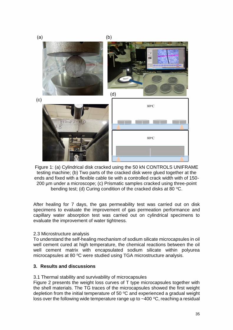
35
Figure 1: (a) Cylindrical disk cracked using the 50 kN CONTROLS UNIFRAME testing machine; (b) Two parts of the cracked disk were glued together at the
ends and fixed with a flexible cable tie with a controlled crack width with of 150-200 µm under a microscope; (c) Prismatic samples cracked using three-point
bending test; (d) Curing condition of the cracked disks at 80 oC.
After healing for 7 days, the gas permeability test was carried out on disk specimens to evaluate the improvement of gas permeation performance and capillary water absorption test was carried out on cylindrical specimens to evaluate the improvement of water tightness.
2.3 Microstructure analysis To understand the self-healing mechanism of sodium silicate microcapsules in oil well cement cured at high temperature, the chemical reactions between the oil well cement matrix with encapsulated sodium silicate within polyurea microcapsules at 80 oC were studied using TGA microstructure analysis. 3. Results and discussions
3.1 Thermal stability and survivability of microcapsules Figure 2 presents the weight loss curves of T type microcapsules together with the shell materials. The TG traces of the microcapsules showed the first weight depletion from the initial temperature of 50 oC and experienced a gradual weight loss over the following wide temperature range up to ~400 oC, reaching a residual
(a) (b)
(c)
(d)
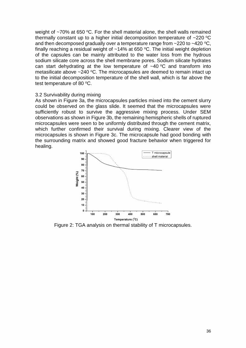
36
weight of ~70% at 650 oC. For the shell material alone, the shell walls remained thermally constant up to a higher initial decomposition temperature of ~220 oC and then decomposed gradually over a temperature range from ~220 to ~420 oC, finally reaching a residual weight of ~14% at 650 oC. The initial weight depletion of the capsules can be mainly attributed to the water loss from the hydrous sodium silicate core across the shell membrane pores. Sodium silicate hydrates can start dehydrating at the low temperature of ~40 oC and transform into metasilicate above ~240 oC. The microcapsules are deemed to remain intact up to the initial decomposition temperature of the shell wall, which is far above the test temperature of 80 oC. 3.2 Survivability during mixing As shown in Figure 3a, the microcapsules particles mixed into the cement slurry could be observed on the glass slide. It seemed that the microcapsules were sufficiently robust to survive the aggressive mixing process. Under SEM observations as shown in Figure 3b, the remaining hemispheric shells of ruptured microcapsules were seen to be uniformly distributed through the cement matrix, which further confirmed their survival during mixing. Clearer view of the microcapsules is shown in Figure 3c. The microcapsule had good bonding with the surrounding matrix and showed good fracture behavior when triggered for healing.
Figure 2: TGA analysis on thermal stability of T microcapsules.
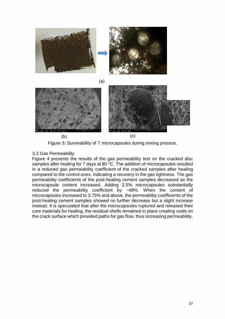
37
Figure 3: Survivability of T microcapsules during mixing process.
3.3 Gas Permeability Figure 4 presents the results of the gas permeability test on the cracked disc samples after healing for 7 days at 80 oC. The addition of microcapsules resulted in a reduced gas permeability coefficient of the cracked samples after healing compared to the control ones, indicating a recovery in the gas tightness. The gas permeability coefficients of the post-healing cement samples decreased as the microcapsule content increased. Adding 2.5% microcapsules substantially reduced the permeability coefficient by ~48%. When the content of microcapsules increased to 3.75% and above, the permeability coefficients of the post-healing cement samples showed no further decrease but a slight increase instead. It is speculated that after the microcapsules ruptured and released their core materials for healing, the residual shells remained in place creating voids on the crack surface which provided paths for gas flow, thus increasing permeability.
(a)
(b) (c)
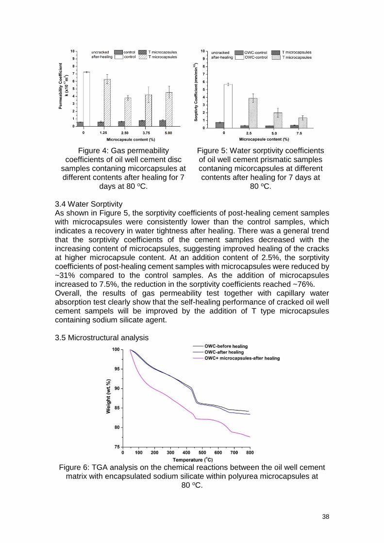
38
Figure 4: Gas permeability
coefficients of oil well cement disc samples contaning micorcapsules at different contents after healing for 7
days at 80 oC.
Figure 5: Water sorptivity coefficients of oil well cement prismatic samples contaning micorcapsules at different contents after healing for 7 days at
80 oC. 3.4 Water Sorptivity As shown in Figure 5, the sorptivity coefficients of post-healing cement samples with microcapsules were consistently lower than the control samples, which indicates a recovery in water tightness after healing. There was a general trend that the sorptivity coefficients of the cement samples decreased with the increasing content of microcapsules, suggesting improved healing of the cracks at higher microcapsule content. At an addition content of 2.5%, the sorptivity coefficients of post-healing cement samples with microcapsules were reduced by ~31% compared to the control samples. As the addition of microcapsules increased to 7.5%, the reduction in the sorptivity coefficients reached ~76%. Overall, the results of gas permeability test together with capillary water absorption test clearly show that the self-healing performance of cracked oil well cement sampels will be improved by the addition of T type microcapsules containing sodium silicate agent. 3.5 Microstructural analysis
Figure 6: TGA analysis on the chemical reactions between the oil well cement
matrix with encapsulated sodium silicate within polyurea microcapsules at 80 oC.
39
As shown in Figure 6, through comparison with the control sample before healing, it is evident that the oil well cement sample treated with crushed microcapsules had reduced weight loss between 400 and 500 oC, while there was more weight loss in the temperature range between 50 and 400 oC, suggesting the consumption of CH and subsequently increased content of C-S-H after healing. The sample treated with only water showed almost identical weight loss in both temperature ranges to the control sample before healing. This further confirmed that there was little continued hydration occurring in the hydrated oil well cement under high temperature curing at 80 oC. Oil well cement cured under a high temperature has very little capability for autogenous healing due to the high degree of cement hydration. The addition of sodium silicate agent induced the consumption of CH and formation of C-S-H, which improved the healing capability of highly hydrated oil well cement pastes. 4 Conclusions The results showed that T microcapsules had good thermal stability up to ~220 oC and enough robustness during the mixing process. The characterisation results verified their suitability for use in oil well cements under high temperature wellbore conditions at 80 oC. According to the microanalysis, when cured under high temperature of 80 oC, the oil well cement paste itself had little self-healing capability. The addition of T microcapsules containing sodium silicate agent significantly improved the self-healing performance of oil well cement pastes. The encapsulated sodium silicate induced the consumption of CH and formation of C-S-H, thereby improving the healing capability of highly hydrated oil well cement pastes. The addition of 2.5% microcapsules resulted in a reduction of ~48% in gas permeability coefficient. The microcapsules showed even better performance in reducing water sorptivity coefficient by ~76% at the addition of 7.5%. Acknowledgement The financial support from Royal Dutch Shell plc, Schlumberger Foundation Faculty for the Future and Cambridge Trust is gratefully acknowledged. References [1] Nelson, E.B., 2006. Well cementing 2nd edition. [2] Carey, B., 2010. Wellbore Integrity and CO2 Sequestration. Los Alamos National Laboratory. [3] Jafariesfad, N., Gong, Y., Geiker, M.R. and Skalle, P., 2016, April. Nano-sized mgo with engineered expansive property for oil well cement systems. In SPE Bergen One Day Seminar. Society of Petroleum Engineers. [4] Shadravan, A., Schubert, J., Amani, M. and Teodoriu, C., 2014, March. HPHT cement sheath integrity evaluation method for unconventional wells. SPE International Conference on Health, Safety, and Environment: The Journey Continues, 1, pp.73–81. [5] Bogue, R., 2012. Smart materials: a review of recent developments. Assem. Autom. 32, 3-7. [6] Schlumberger, 2014. Future Self-Healing Cement System. Available at: https://www.slb.com/services/drilling/cementing/self_healing_cement.aspx. [7] White, S.R., Blaiszik, B.J., Kramer, S.L., Olugebefola, S.C., Moore, J.S. and Sottos, N.R., 2010. Self-healing Polymers and Composites: Capsules, circulatory
40
systems and chemistry allow materials to fix themselves. American Scientist, 99(5), pp.392-399. [8] Pelletier, M.M., Brown, R., Shukla, A. and Bose, A., 2010. Self-healing concrete with a microencapsulated healing agent. University of Rhode Island, Kingston,USA, (C). [9] Huang, H. & Ye, G., 2011a. Application of sodium silicate solution as self-healing agent in cementitious materials. International RILEM Conference on Advances in Construction Materials Through Science and Engineering, (June 2015), pp.530–536. [10] Gilford III, J., Hassan, M.M., Rupnow, T., Barbato, M., Okeil, A. and Asadi, S., 2013. Dicyclopentadiene and sodium silicate microencapsulation for self-healing of concrete. Journal of Materials in Civil Engineering, 26(5), pp.886-896. [11] Giannaros, P., Kanellopoulos, A. & Al-Tabbaa, A., 2016. Sealing of cracks in cement using microencapsulated sodium silicate. Smart Materials and Structures, July 2016. [12] Mostavi, E., Asadi, S., Hassan, M.M. and Alansari, M., 2015. Evaluation of self-healing mechanisms in concrete with double-walled sodium silicate microcapsules. Journal of Materials in Civil Engineering, 27(12), p.04015035.
Session 2 Design of reinforced concrete tailored
for extreme conditions: compatibility of smart admixtures and effects on fresh
and hardened concrete
42
Multifunctional bulk reinforced-concrete materials to operate under severe conditions
Emmanuel Galluci1
1 Sika Technology AG, Zugerstrasse 50, Baar, 6340, Switzerland; e-mail: [email protected]
Abstract The Lorcenis project has the ambition of extending the service life of energy infrastructures exposed to some of the harshest environmental conditions, through the implementation of novel additive types not used in today's concrete practice. The performance requirements implied the development of a dozen of state-of-the-art technological concrete mix designs which had to: (1) meet the most challenging specifications identified through an in-depth analysis of today's field best practice and; (2) be incrementally modified to afford the implementation of Lorcenis' novel additives while maintaining their fresh and hardened properties. This keynote aims at giving an overview of the whole process chain, from the identification and definition of the effective environmental conditions and their impact on exposed concrete structures, the best-in-practice corresponding concrete mix designs and their development, the implementation of the novel durability additives and evaluation of their efficiency through accelerated durability testing according to the international norm protocols.
43
Durable and sustainable reinforced concretes obtained through the combination of calcium sulfoaluminate cement-based concretes
and non-corrosive reinforcements
F. Bertola1, F. Canonico1, D. Gastaldi1 and S. Irico2
1 Research and Development, Buzzi Unicem, via Luigi Buzzi 6, 15033 Casale Monferrato, Italy
– [email protected]; [email protected]; [email protected] 2 Research and Development, Wilhelm Dyckerhoff Institut (WDI), Dyckerhoff Strasse 7, 65203 Wiesbaden, Germany – [email protected]
Abstract In an aggressive environment, standard reinforced concrete (RC) made with Portland cement and steel reinforcement may be affected by a lack of durability, particularly due to steel corrosion, if the concrete is not properly designed. A promising alternative to traditional practice is offered by the combination of a high-performance concrete with Glass Fiber Reinforced Polymers (GFRP) bars. A new technological solution is proposed coupling GFRP and sulfoaluminate (CSA) cement, allowing multiple advantages: (1) a significant improvement of early age strength and dimensional stability is obtained in addition to the durability deriving from alternative reinforcement (2) higher sustainability results from the lower CO2 emissions involved in CSA cement production compared to ordinary Portland cement (3) the adoption of GFRP technology, being free from corrosion risks, allows the use of recycled materials or materials available in large quantities (i.e. seawater), even if contaminated by chlorides, thereby saving natural resources. This work presents the results obtained through laboratory investigations carried out with the aim of proving the different performance obtainable in comparison with traditional systems constituted of Portland cement concretes and reinforced with carbon steel. In addition, selected results of an experimental investigation are shown, during which a commercially available CSA cement was used to produce concrete mixes with fresh water or seawater and reinforced with GFRP bars. Keywords: Calcium sulfoaluminate cement, GFRP reinforcement, seawater, sustainability 1. Introduction Corrosion of steel reinforcement is the primary cause of durability problems in Reinforced Concrete (RC) structures [1]. Traditionally, the seek for steel protective strategies is considered the main route to solve this problem (e.g. designing concrete mixes with limited permeability and superior durability characteristics). Nevertheless, the maintenance costs of preventing steel reinforcement corrosion, and the huge cost of repair or replacement of concrete structures, deteriorated due to corrosion, have fostered a worldwide interest in finding alternative materials for RC structures. In the past few years many research projects have been funded in order to develop RC resistant to high aggressive environments. A successful example is represented by the SEACON project (http://seacon.umsml.com/), that focused on solutions based on non-corrosive reinforcing bars for applications in aggressive environment. One of the most challenging outcome of the SEACON project was the use of Glass Fiber Reinforced Polymers (GFRP) bars as an alternative to traditional carbon steel (CS) reinforcement. GFRP are composite materials consisting of longitudinal high-strength
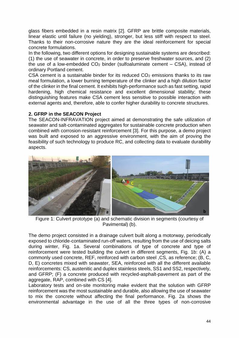
44
glass fibers embedded in a resin matrix [2]. GFRP are brittle composite materials, linear elastic until failure (no yielding), stronger, but less stiff with respect to steel. Thanks to their non-corrosive nature they are the ideal reinforcement for special concrete formulations. In the following, two different options for designing sustainable systems are described: (1) the use of seawater in concrete, in order to preserve freshwater sources, and (2) the use of a low-embedded CO2 binder (sulfoaluminate cement – CSA), instead of ordinary Portland cement. CSA cement is a sustainable binder for its reduced CO2 emissions thanks to its raw meal formulation, a lower burning temperature of the clinker and a high dilution factor of the clinker in the final cement. It exhibits high-performance such as fast setting, rapid hardening, high chemical resistance and excellent dimensional stability; these distinguishing features make CSA cement less sensitive to possible interaction with external agents and, therefore, able to confer higher durability to concrete structures. 2. GFRP in the SEACON Project The SEACON-INFRAVATION project aimed at demonstrating the safe utilization of seawater and salt-contaminated aggregates for sustainable concrete production when combined with corrosion-resistant reinforcement [3]. For this purpose, a demo project was built and exposed to an aggressive environment, with the aim of proving the feasibility of such technology to produce RC, and collecting data to evaluate durability aspects.
Figure 1: Culvert prototype (a) and schematic division in segments (courtesy of
Pavimental) (b).
The demo project consisted in a drainage culvert built along a motorway, periodically exposed to chloride-contaminated run-off waters, resulting from the use of deicing salts during winter, Fig. 1a. Several combinations of type of concrete and type of reinforcement were tested building the culvert in different segments, Fig. 1b: (A) a commonly used concrete, REF, reinforced with carbon steel ,CS, as reference; (B, C, D, E) concretes mixed with seawater, SEA, reinforced with all the different available reinforcements: CS, austenitic and duplex stainless steels, SS1 and SS2, respectively, and GFRP; (F) a concrete produced with recycled-asphalt-pavement as part of the aggregate, RAP, combined with CS [4]. Laboratory tests and on-site monitoring make evident that the solution with GFRP reinforcement was the most sustainable and durable, also allowing the use of seawater to mix the concrete without affecting the final performance. Fig. 2a shows the environmental advantage in the use of all the three types of non-corrosive
a b
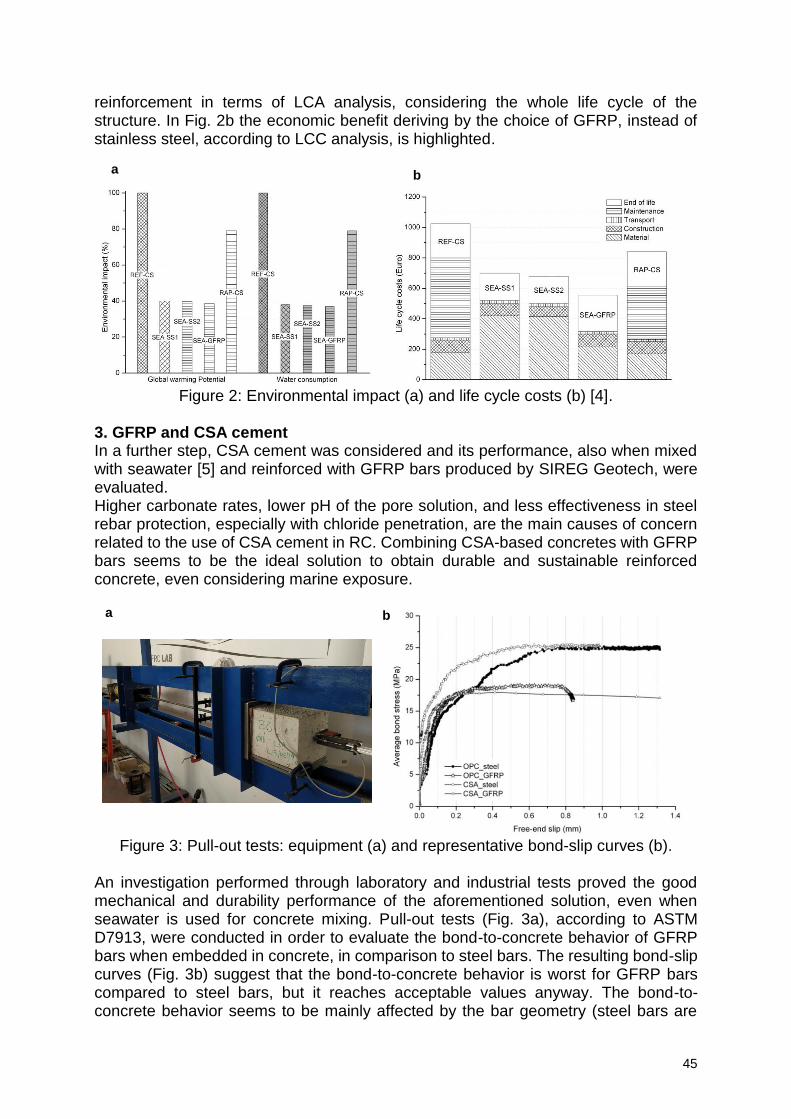
45
reinforcement in terms of LCA analysis, considering the whole life cycle of the structure. In Fig. 2b the economic benefit deriving by the choice of GFRP, instead of stainless steel, according to LCC analysis, is highlighted.
Figure 2: Environmental impact (a) and life cycle costs (b) [4].
3. GFRP and CSA cement In a further step, CSA cement was considered and its performance, also when mixed with seawater [5] and reinforced with GFRP bars produced by SIREG Geotech, were evaluated. Higher carbonate rates, lower pH of the pore solution, and less effectiveness in steel rebar protection, especially with chloride penetration, are the main causes of concern related to the use of CSA cement in RC. Combining CSA-based concretes with GFRP bars seems to be the ideal solution to obtain durable and sustainable reinforced concrete, even considering marine exposure.
Figure 3: Pull-out tests: equipment (a) and representative bond-slip curves (b).
An investigation performed through laboratory and industrial tests proved the good mechanical and durability performance of the aforementioned solution, even when seawater is used for concrete mixing. Pull-out tests (Fig. 3a), according to ASTM D7913, were conducted in order to evaluate the bond-to-concrete behavior of GFRP bars when embedded in concrete, in comparison to steel bars. The resulting bond-slip curves (Fig. 3b) suggest that the bond-to-concrete behavior is worst for GFRP bars compared to steel bars, but it reaches acceptable values anyway. The bond-to-concrete behavior seems to be mainly affected by the bar geometry (steel bars are
a b
a b
46
more ribbed than GFRP ones) and not influenced by the type of concrete (OPC or CSA based), when the concrete strength is similar. 4. Conclusions In this paper, a successful combination of innovative materials to design sustainable and durable RC, that could not be otherwise produced with conventional systems, is disclosed. The experimental results, obtained and partly presented in this document, represent a promising start point in the development of innovative technologies, but they also stress on the need of more research on mechanical performance in real environmental and loading conditions. At the moment, a wide spread of GFRP is still limited by the uncertainty in their performance, mainly due to non-uniformity in standard testing procedures and to a lack in the quality controls during manufacturing. CSA cement, although being more environmental friendly compared to OPC, is merely produced on a niche scale and is more expensive than OPC. Despite the aforementioned concerns, for specific concrete applications, the proposed technology could be advantageous in terms of final cost, CO2 saving and durability gain. Acknowledgements The financial support from INFRAVATION (GA#31109806.0005-SEACON) is gratefully acknowledge. The authors are grateful to FRC Lab s.r.l. and SIREG Geotech s.r.l. for providing the expertise that greatly assisted the authors in their research. References [1] L. Bertolini, B. Elsener, P. Pedeferri, E. Redaelli and R. Polder, Corrosion of Steel in Concrete: Prevention, Diagnosis, Repair (2nd ed.), John Wiley & Sons, Hoboken, NJ, 2013. https://www.wiley.com/en-. [2] A. Nanni, Composites: Coming on Strong, Concrete Construction 44(1999) pp. 120. [3] F. Bertola, D. Gastaldi, F. Canonico, and Nanni, SEACON Project: sustainable concrete using seawater, salt-contaminated aggregates, and non-corrosive reinforcement, Durability of Building Materials and Components conference, Ghent (B), May 29-31 2017 [4] E. Redaelli, A. Arrigoni, M. Carsana, G. Dotelli, M. Gastaldi, F. Lollini, F. Bertola, F. Canonico, and A. Nanni, Culvert Prototype Made with Seawater Concrete: Materials Characterization, Monitoring, and Environmental Impact, Advances in Civil Engineering Materials (2019), DOI: 10.1520/ACEM20180114 [5] F. Bertola, D. Gastaldi, and F. Canonico, Behavior of Specialty Binders Mixed with Seawater, Advances in Civil Engineering Materials (2019), DOI: 10.1520/ACEM20180107
47
Self-healing approach on early age cracked concretes with smart admixture
V. Cappellesso1, D. Silva1, N. Petry1, J. Arndt1, A. Masuero2, D. Dal Molin2
1Department of Civil Engineering, Cementitious Materials Self-healing Group, Núcleo Orientado para a Inovação da Construção (NORIE), Universidade Federal do Rio Grande do Sul, Osvaldo Aranha 99, 90035-190, Porto Alegre, Brazil – [email protected]; [email protected]; [email protected]; [email protected]; [email protected]; [email protected].
Abstract Cementitious materials cracks are considered the most incident pathological manifestations in concrete structures and are created from different mechanisms, such as the external action of thermal variations. In some occasions, the cracks are not avoided, even if the design concept and building precautions were taken. Regarding to that, it is suggested that the life cycle of concrete structures can be increased when they are produced with smart mixtures, which have the capacity to develop or to create the healing properties on these materials surfaces, without human interference. Self-healing phenomena are approached in this paper through experiments on concrete specimens containing high early strength cement and a smart mixture (silica fume in fluid or suspension) in the rates of 0%, 5%, 10% and 15% per cement weight, and water/cement ratio of 0.40. The samples were produced, cracked on early age, and submitted to wet/dry cycles during the curing process. The specimens were then characterized by compression strength, while the self-healing phenomenon was evaluated though ultrasonic pulse – which allows observing the liquid tightness recovery - and microscope imaging techniques, both for 91 days. A potential self-healing behavior was observed for all concretes and was better evidenced in 5% silica fume suspension content, however, for the analysis time there was no complete cracks closure. Keywords: concrete, self-healing, smart admixtures, silica fume, early age cracks 1. Introduction Cracked concretes allow aggressive agents access and consequently structures degrading in reinforced concrete. Small cracks can be sealed through a healing phenomenon and smart mixtures can improve this process. This work proposes to evaluate a silica fume suspension admixture with the propose to modify cement-based microstructures, hydration products, watertightness and cracks closure in smart concretes [1][2]. 2. Materials and methods 2.1 Materials Concretes was made with the follow materials: a) cement: high initial strength (Type IIA - BS 8500-1 2015) with 10% limestone, specific mass 3.12 g/cm³ and specific area 6232 m²/g; b) fine aggregate: natural quartz sand with a fineness modulus equal to 1.89; c) coarse aggregate: basalt, maximum dimension of 2.5mm;
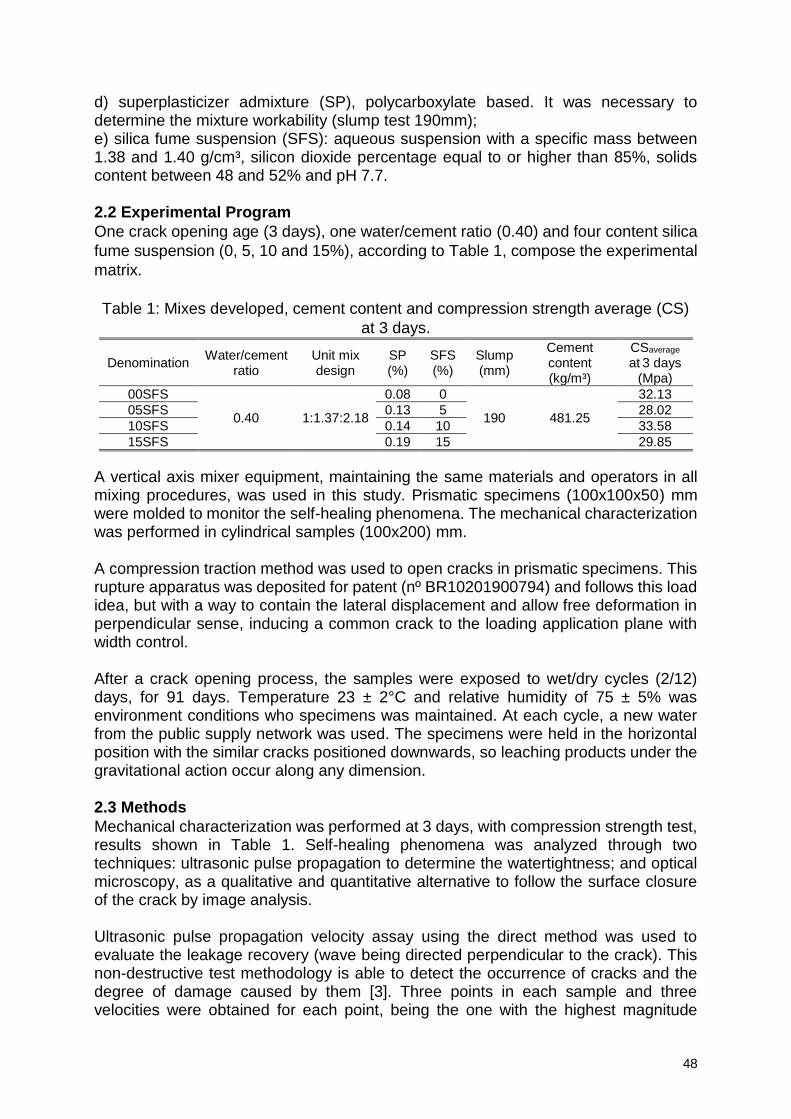
48
d) superplasticizer admixture (SP), polycarboxylate based. It was necessary to determine the mixture workability (slump test 190mm); e) silica fume suspension (SFS): aqueous suspension with a specific mass between 1.38 and 1.40 g/cm³, silicon dioxide percentage equal to or higher than 85%, solids content between 48 and 52% and pH 7.7. 2.2 Experimental Program
One crack opening age (3 days), one water/cement ratio (0.40) and four content silica
fume suspension (0, 5, 10 and 15%), according to Table 1, compose the experimental
matrix.
Table 1: Mixes developed, cement content and compression strength average (CS)
at 3 days.
Denomination Water/cement
ratio Unit mix design
SP (%)
SFS (%)
Slump (mm)
Cement content (kg/m³)
CSaverage at 3 days
(Mpa)
00SFS
0.40 1:1.37:2.18
0.08 0
190 481.25
32.13
05SFS 0.13 5 28.02
10SFS 0.14 10 33.58
15SFS 0.19 15 29.85
A vertical axis mixer equipment, maintaining the same materials and operators in all mixing procedures, was used in this study. Prismatic specimens (100x100x50) mm were molded to monitor the self-healing phenomena. The mechanical characterization was performed in cylindrical samples (100x200) mm. A compression traction method was used to open cracks in prismatic specimens. This rupture apparatus was deposited for patent (nº BR10201900794) and follows this load idea, but with a way to contain the lateral displacement and allow free deformation in perpendicular sense, inducing a common crack to the loading application plane with width control. After a crack opening process, the samples were exposed to wet/dry cycles (2/12) days, for 91 days. Temperature 23 ± 2°C and relative humidity of 75 ± 5% was environment conditions who specimens was maintained. At each cycle, a new water from the public supply network was used. The specimens were held in the horizontal position with the similar cracks positioned downwards, so leaching products under the gravitational action occur along any dimension. 2.3 Methods
Mechanical characterization was performed at 3 days, with compression strength test, results shown in Table 1. Self-healing phenomena was analyzed through two techniques: ultrasonic pulse propagation to determine the watertightness; and optical microscopy, as a qualitative and quantitative alternative to follow the surface closure of the crack by image analysis. Ultrasonic pulse propagation velocity assay using the direct method was used to evaluate the leakage recovery (wave being directed perpendicular to the crack). This non-destructive test methodology is able to detect the occurrence of cracks and the degree of damage caused by them [3]. Three points in each sample and three velocities were obtained for each point, being the one with the highest magnitude
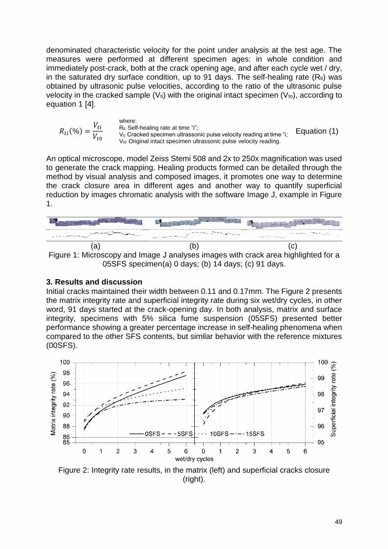
49
denominated characteristic velocity for the point under analysis at the test age. The measures were performed at different specimen ages: in whole condition and immediately post-crack, both at the crack opening age, and after each cycle wet / dry, in the saturated dry surface condition, up to 91 days. The self-healing rate (Rti) was obtained by ultrasonic pulse velocities, according to the ratio of the ultrasonic pulse velocity in the cracked sample (Vti) with the original intact specimen (Vto), according to equation 1 [4].
𝑅𝑡𝑖(%) =𝑉𝑡𝑖
𝑉𝑡0
where: Rti: Self-healing rate at time “i”; Vti: Cracked specimen ultrassonic pulse velocity reading at time “i; Vt0: Original intact specimen ultrassonic pulse velocity reading.
Equation (1)
An optical microscope, model Zeiss Stemi 508 and 2x to 250x magnification was used to generate the crack mapping. Healing products formed can be detailed through the method by visual analysis and composed images, it promotes one way to determine the crack closure area in different ages and another way to quantify superficial reduction by images chromatic analysis with the software Image J, example in Figure 1.
(a) (b) (c)
Figure 1: Microscopy and Image J analyses images with crack area highlighted for a 05SFS specimen(a) 0 days; (b) 14 days; (c) 91 days.
3. Results and discussion
Initial cracks maintained their width between 0.11 and 0.17mm. The Figure 2 presents the matrix integrity rate and superficial integrity rate during six wet/dry cycles, in other word, 91 days started at the crack-opening day. In both analysis, matrix and surface integrity, specimens with 5% silica fume suspension (05SFS) presented better performance showing a greater percentage increase in self-healing phenomena when compared to the other SFS contents, but similar behavior with the reference mixtures (00SFS).
Figure 2: Integrity rate results, in the matrix (left) and superficial cracks closure
(right).
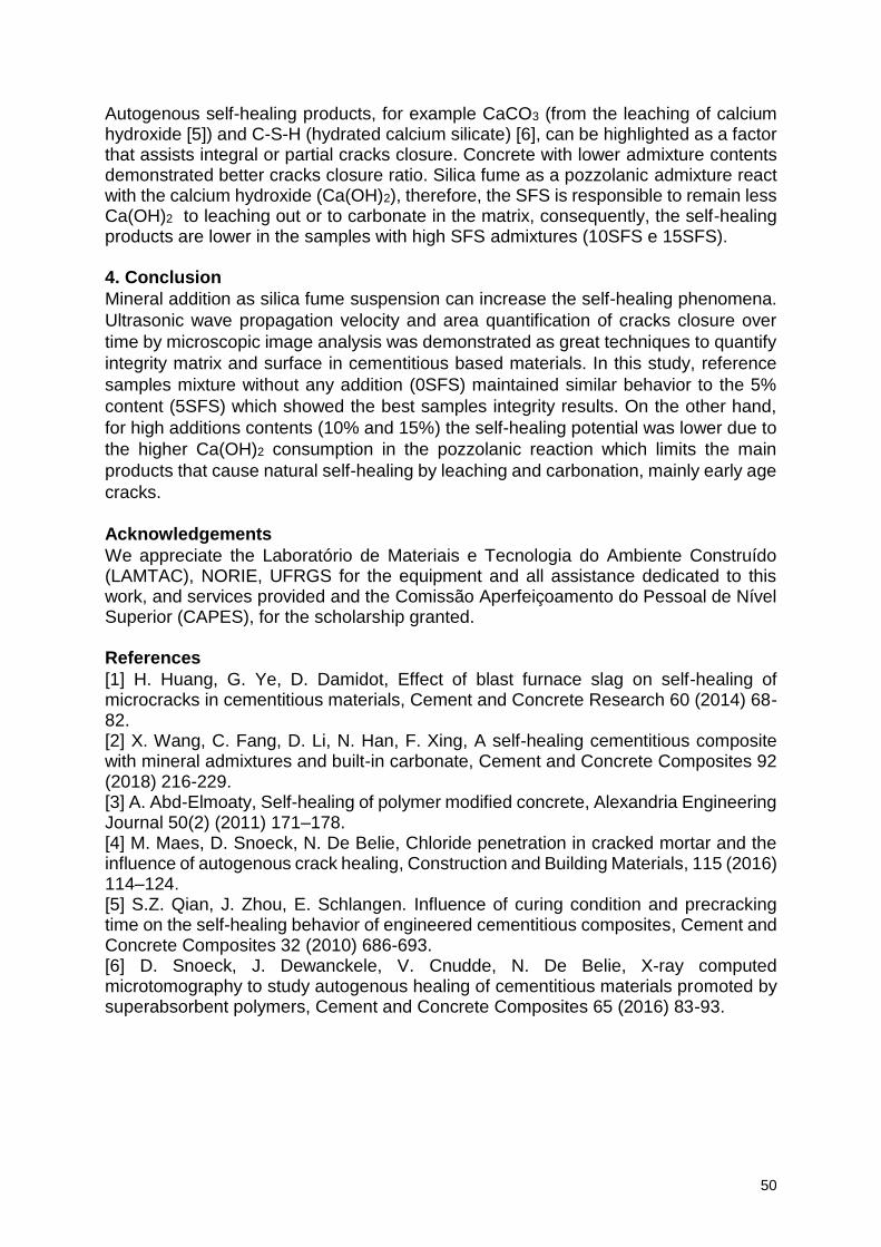
50
Autogenous self-healing products, for example CaCO3 (from the leaching of calcium hydroxide [5]) and C-S-H (hydrated calcium silicate) [6], can be highlighted as a factor that assists integral or partial cracks closure. Concrete with lower admixture contents demonstrated better cracks closure ratio. Silica fume as a pozzolanic admixture react with the calcium hydroxide (Ca(OH)2), therefore, the SFS is responsible to remain less Ca(OH)2 to leaching out or to carbonate in the matrix, consequently, the self-healing products are lower in the samples with high SFS admixtures (10SFS e 15SFS). 4. Conclusion
Mineral addition as silica fume suspension can increase the self-healing phenomena.
Ultrasonic wave propagation velocity and area quantification of cracks closure over
time by microscopic image analysis was demonstrated as great techniques to quantify
integrity matrix and surface in cementitious based materials. In this study, reference
samples mixture without any addition (0SFS) maintained similar behavior to the 5%
content (5SFS) which showed the best samples integrity results. On the other hand,
for high additions contents (10% and 15%) the self-healing potential was lower due to
the higher Ca(OH)2 consumption in the pozzolanic reaction which limits the main
products that cause natural self-healing by leaching and carbonation, mainly early age
cracks.
Acknowledgements
We appreciate the Laboratório de Materiais e Tecnologia do Ambiente Construído (LAMTAC), NORIE, UFRGS for the equipment and all assistance dedicated to this work, and services provided and the Comissão Aperfeiçoamento do Pessoal de Nível Superior (CAPES), for the scholarship granted. References
[1] H. Huang, G. Ye, D. Damidot, Effect of blast furnace slag on self-healing of microcracks in cementitious materials, Cement and Concrete Research 60 (2014) 68-82. [2] X. Wang, C. Fang, D. Li, N. Han, F. Xing, A self-healing cementitious composite with mineral admixtures and built-in carbonate, Cement and Concrete Composites 92 (2018) 216-229. [3] A. Abd-Elmoaty, Self-healing of polymer modified concrete, Alexandria Engineering Journal 50(2) (2011) 171–178. [4] M. Maes, D. Snoeck, N. De Belie, Chloride penetration in cracked mortar and the influence of autogenous crack healing, Construction and Building Materials, 115 (2016) 114–124. [5] S.Z. Qian, J. Zhou, E. Schlangen. Influence of curing condition and precracking time on the self-healing behavior of engineered cementitious composites, Cement and Concrete Composites 32 (2010) 686-693. [6] D. Snoeck, J. Dewanckele, V. Cnudde, N. De Belie, X-ray computed microtomography to study autogenous healing of cementitious materials promoted by superabsorbent polymers, Cement and Concrete Composites 65 (2016) 83-93.
51
Effect of Layered Double Hydroxides on the Performance and Service Life of Reinforced Concrete
Celestino Gomes1, Zahid Mir2, Rui Silva Sampaio1, A.C. Bastos1, Frederico Maia3,
Cláudia Rocha3, João Tedim1, M.G.S. Ferreira1
1DEMaC – Department of Materials and Ceramic Engineering and CICECO – Aveiro Institute of Materials, Universidade de Aveiro, 3810-193 Aveiro, Portugal – [email protected]; [email protected]; [email protected]; [email protected]; [email protected]; 2Institute of Materials Research, Helmholtz-Zentrum Geesthacht, Max-Planck-Straße 1, Geesthacht 21502, Germany – [email protected]; 3Smallmatek - Rua dos Canhas, 3810-075 Aveiro, Portugal – [email protected]; [email protected];
Abstract Layered double hydroxides (LDH) are anionic clays exploited as ion exchangers, catalysts or adsorbents, in industry and medicine. The application to corrosion control of reinforced concrete is being investigated, based on their capacity to capture aggressive anions from the environment (like chloride ions) and simultaneously release corrosion inhibitors. This communication presents the work done in the LORCENIS project using LDH. Two types of LDH were used, Zn-Al intercalated with nitrate or nitrite ions. Studies were performed in chloride and carbonated media as well as in cementitious materials. The main parameters investigated were LDH stability in high pH, the compatibility with cementitious materials, the effect on the curing of concrete, selectivity of the ionic exchange process, kinetics of the ionic exchange and the role of LDH inside concrete. Keywords: Layered double hydroxides, (LDH), corrosion, inhibition, durability. 1. Introduction In the last decades there has been a growing interest in developing new or modified materials capable to prevent or delay corrosion of ordinary steel rebars used in reinforced concrete structures. Layered Double Hydroxides are one of such materials, which can be artificially prepared to offer enhanced properties compared to the naturally occurring hydrotalcite minerals. LDH are constituted by layers of bivalent and trivalent metal hydroxides with water in between and anions to balance the overall electrical charge. These anions can exchange with other negative species from the environment, and this is the property that makes LDH so interesting in many technological applications. Since it is well known that chloride and carbonate ions are responsible for deterioration processes within reinforced concrete - promoting the onset and the corrosion rates of the steel rebars – there is the proposition of using the anionic exchange capabilities of LDH to capture these negative aggressive ions to delay the corrosion initiation of the rebars, thus prolonging the service life of reinforced concrete structures. In this communication, results are presented regarding the use of LDH intercalated with nitrate and nitrite ions (the latter, a known corrosion inhibitor for steel in alkaline environment) and its effect on the corrosion of steel rebars in mortar and concrete pore solution samples.
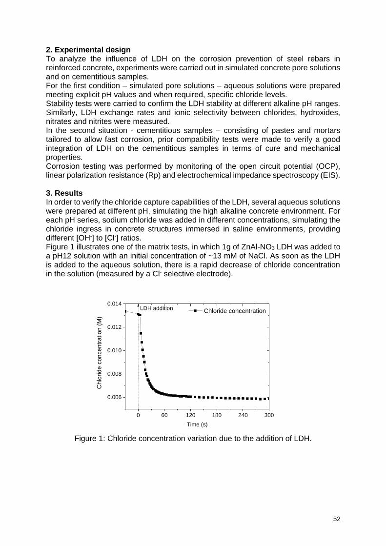
52
2. Experimental design To analyze the influence of LDH on the corrosion prevention of steel rebars in reinforced concrete, experiments were carried out in simulated concrete pore solutions and on cementitious samples. For the first condition – simulated pore solutions – aqueous solutions were prepared meeting explicit pH values and when required, specific chloride levels. Stability tests were carried to confirm the LDH stability at different alkaline pH ranges. Similarly, LDH exchange rates and ionic selectivity between chlorides, hydroxides, nitrates and nitrites were measured. In the second situation - cementitious samples – consisting of pastes and mortars tailored to allow fast corrosion, prior compatibility tests were made to verify a good integration of LDH on the cementitious samples in terms of cure and mechanical properties. Corrosion testing was performed by monitoring of the open circuit potential (OCP), linear polarization resistance (Rp) and electrochemical impedance spectroscopy (EIS). 3. Results In order to verify the chloride capture capabilities of the LDH, several aqueous solutions were prepared at different pH, simulating the high alkaline concrete environment. For each pH series, sodium chloride was added in different concentrations, simulating the chloride ingress in concrete structures immersed in saline environments, providing different [OH-] to [Cl-] ratios. Figure 1 illustrates one of the matrix tests, in which 1g of ZnAl-NO3 LDH was added to a pH12 solution with an initial concentration of ~13 mM of NaCl. As soon as the LDH is added to the aqueous solution, there is a rapid decrease of chloride concentration in the solution (measured by a Cl- selective electrode).
Figure 1: Chloride concentration variation due to the addition of LDH.
0 60 120 180 240 300
0.006
0.008
0.010
0.012
0.014
Ch
lorid
e c
on
cen
tra
tio
n (
M)
Time (s)
Chloride concentrationLDH addition
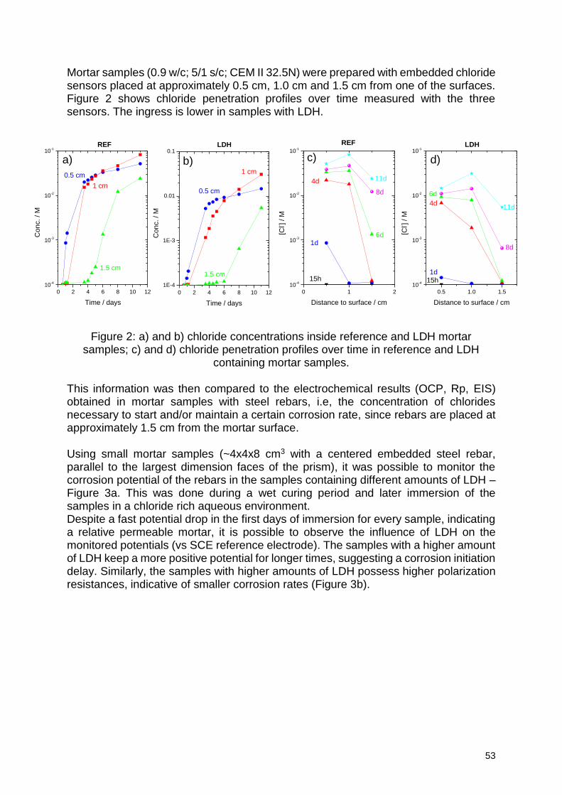
53
Mortar samples (0.9 w/c; 5/1 s/c; CEM II 32.5N) were prepared with embedded chloride sensors placed at approximately 0.5 cm, 1.0 cm and 1.5 cm from one of the surfaces. Figure 2 shows chloride penetration profiles over time measured with the three sensors. The ingress is lower in samples with LDH.
Figure 2: a) and b) chloride concentrations inside reference and LDH mortar
samples; c) and d) chloride penetration profiles over time in reference and LDH containing mortar samples.
This information was then compared to the electrochemical results (OCP, Rp, EIS) obtained in mortar samples with steel rebars, i.e, the concentration of chlorides necessary to start and/or maintain a certain corrosion rate, since rebars are placed at approximately 1.5 cm from the mortar surface. Using small mortar samples (~4x4x8 cm3 with a centered embedded steel rebar, parallel to the largest dimension faces of the prism), it was possible to monitor the corrosion potential of the rebars in the samples containing different amounts of LDH – Figure 3a. This was done during a wet curing period and later immersion of the samples in a chloride rich aqueous environment. Despite a fast potential drop in the first days of immersion for every sample, indicating a relative permeable mortar, it is possible to observe the influence of LDH on the monitored potentials (vs SCE reference electrode). The samples with a higher amount of LDH keep a more positive potential for longer times, suggesting a corrosion initiation delay. Similarly, the samples with higher amounts of LDH possess higher polarization resistances, indicative of smaller corrosion rates (Figure 3b).
0 2 4 6 8 10 12
10-4
10-3
10-2
10-1
REF
0.5 cm
1 cm
Conc. / M
Time / days
1.5 cm
a)
0 2 4 6 8 10 12
1E-4
1E-3
0.01
0.1
0.5 cm
1 cm
Conc. / M
Time / days
1.5 cm
LDH
b)
0 1 2
10-4
10-3
10-2
10-1
11d
8d
6d
4d
1d
[Cl- ]
/ M
Distance to surface / cm
REF
15h
c)
0.5 1.0 1.5
10-4
10-3
10-2
10-1
11d
8d
6d
4d
1d
[Cl- ]
/ M
Distance to surface / cm
LDH
15h
d)
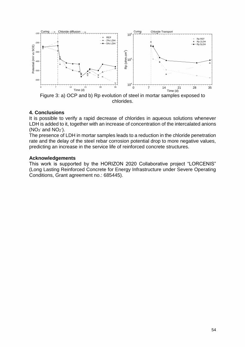
54
Figure 3: a) OCP and b) Rp evolution of steel in mortar samples exposed to
chlorides.
4. Conclusions It is possible to verify a rapid decrease of chlorides in aqueous solutions whenever LDH is added to it, together with an increase of concentration of the intercalated anions (NO3
- and NO2-).
The presence of LDH in mortar samples leads to a reduction in the chloride penetration rate and the delay of the steel rebar corrosion potential drop to more negative values, predicting an increase in the service life of reinforced concrete structures. Acknowledgements This work is supported by the HORIZON 2020 Collaborative project “LORCENIS” (Long Lasting Reinforced Concrete for Energy Infrastructure under Severe Operating Conditions, Grant agreement no.: 685445).
0 7 14 21 28 35
-600
-500
-400
-300
-200
-100
REF
2% LDH
5% LDH
Pote
ntial (m
V v
s S
CE
)
Time (d)
Curing Chloride diffusion
0 7 14 21 28 3510
4
105
106
Rp REF
Rp 2LDH
Rp 5LDH
Rp (
oh
m.c
m2)
Time (d)
Curing Chloride Transport
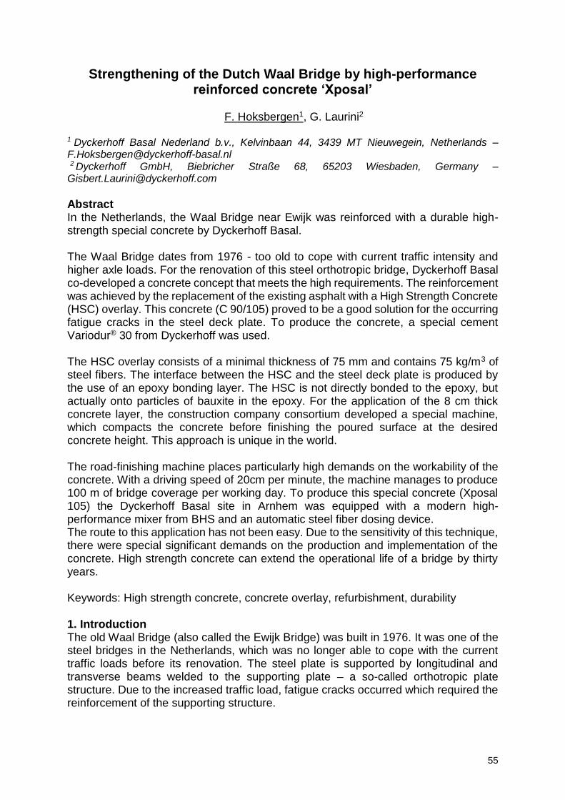
55
Strengthening of the Dutch Waal Bridge by high-performance reinforced concrete ‘Xposal’
F. Hoksbergen1, G. Laurini2
1 Dyckerhoff Basal Nederland b.v., Kelvinbaan 44, 3439 MT Nieuwegein, Netherlands – [email protected] 2 Dyckerhoff GmbH, Biebricher Straße 68, 65203 Wiesbaden, Germany – [email protected]
Abstract In the Netherlands, the Waal Bridge near Ewijk was reinforced with a durable high-strength special concrete by Dyckerhoff Basal. The Waal Bridge dates from 1976 - too old to cope with current traffic intensity and higher axle loads. For the renovation of this steel orthotropic bridge, Dyckerhoff Basal co-developed a concrete concept that meets the high requirements. The reinforcement was achieved by the replacement of the existing asphalt with a High Strength Concrete (HSC) overlay. This concrete (C 90/105) proved to be a good solution for the occurring fatigue cracks in the steel deck plate. To produce the concrete, a special cement Variodur® 30 from Dyckerhoff was used. The HSC overlay consists of a minimal thickness of 75 mm and contains 75 kg/m3 of steel fibers. The interface between the HSC and the steel deck plate is produced by the use of an epoxy bonding layer. The HSC is not directly bonded to the epoxy, but actually onto particles of bauxite in the epoxy. For the application of the 8 cm thick concrete layer, the construction company consortium developed a special machine, which compacts the concrete before finishing the poured surface at the desired concrete height. This approach is unique in the world. The road-finishing machine places particularly high demands on the workability of the concrete. With a driving speed of 20cm per minute, the machine manages to produce 100 m of bridge coverage per working day. To produce this special concrete (Xposal 105) the Dyckerhoff Basal site in Arnhem was equipped with a modern high-performance mixer from BHS and an automatic steel fiber dosing device. The route to this application has not been easy. Due to the sensitivity of this technique, there were special significant demands on the production and implementation of the concrete. High strength concrete can extend the operational life of a bridge by thirty years. Keywords: High strength concrete, concrete overlay, refurbishment, durability 1. Introduction The old Waal Bridge (also called the Ewijk Bridge) was built in 1976. It was one of the steel bridges in the Netherlands, which was no longer able to cope with the current traffic loads before its renovation. The steel plate is supported by longitudinal and transverse beams welded to the supporting plate – a so-called orthotropic plate structure. Due to the increased traffic load, fatigue cracks occurred which required the reinforcement of the supporting structure.
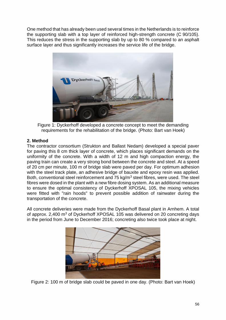
56
One method that has already been used several times in the Netherlands is to reinforce the supporting slab with a top layer of reinforced high-strength concrete (C 90/105). This reduces the stress in the supporting slab by up to 80 % compared to an asphalt surface layer and thus significantly increases the service life of the bridge.
Figure 1: Dyckerhoff developed a concrete concept to meet the demanding
requirements for the rehabilitation of the bridge. (Photo: Bart van Hoek) 2. Method The contractor consortium (Strukton and Ballast Nedam) developed a special paver for paving this 8 cm thick layer of concrete, which places significant demands on the uniformity of the concrete. With a width of 12 m and high compaction energy, the paving train can create a very strong bond between the concrete and steel. At a speed of 20 cm per minute, 100 m of bridge slab were paved per day. For optimum adhesion with the steel track plate, an adhesive bridge of bauxite and epoxy resin was applied. Both, conventional steel reinforcement and 75 kg/m3 steel fibres, were used. The steel fibres were dosed in the plant with a new fibre dosing system. As an additional measure to ensure the optimal consistency of Dyckerhoff XPOSAL 105, the mixing vehicles were fitted with "rain hoods" to prevent possible addition of rainwater during the transportation of the concrete. All concrete deliveries were made from the Dyckerhoff Basal plant in Arnhem. A total of approx. 2,400 m3 of Dyckerhoff XPOSAL 105 was delivered on 20 concreting days in the period from June to December 2016; concreting also twice took place at night.
Figure 2: 100 m of bridge slab could be paved in one day. (Photo: Bart van Hoek)
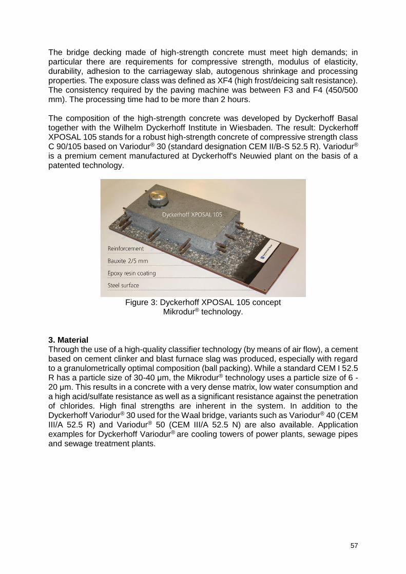
57
The bridge decking made of high-strength concrete must meet high demands; in particular there are requirements for compressive strength, modulus of elasticity, durability, adhesion to the carriageway slab, autogenous shrinkage and processing properties. The exposure class was defined as XF4 (high frost/deicing salt resistance). The consistency required by the paving machine was between F3 and F4 (450/500 mm). The processing time had to be more than 2 hours. The composition of the high-strength concrete was developed by Dyckerhoff Basal together with the Wilhelm Dyckerhoff Institute in Wiesbaden. The result: Dyckerhoff XPOSAL 105 stands for a robust high-strength concrete of compressive strength class C 90/105 based on Variodur® 30 (standard designation CEM II/B-S 52.5 R). Variodur® is a premium cement manufactured at Dyckerhoff's Neuwied plant on the basis of a patented technology.
Figure 3: Dyckerhoff XPOSAL 105 concept
Mikrodur® technology. 3. Material Through the use of a high-quality classifier technology (by means of air flow), a cement based on cement clinker and blast furnace slag was produced, especially with regard to a granulometrically optimal composition (ball packing). While a standard CEM I 52.5 R has a particle size of 30-40 μm, the Mikrodur® technology uses a particle size of 6 - 20 μm. This results in a concrete with a very dense matrix, low water consumption and a high acid/sulfate resistance as well as a significant resistance against the penetration of chlorides. High final strengths are inherent in the system. In addition to the Dyckerhoff Variodur® 30 used for the Waal bridge, variants such as Variodur® 40 (CEM III/A 52.5 R) and Variodur® 50 (CEM III/A 52.5 N) are also available. Application examples for Dyckerhoff Variodur® are cooling towers of power plants, sewage pipes and sewage treatment plants.
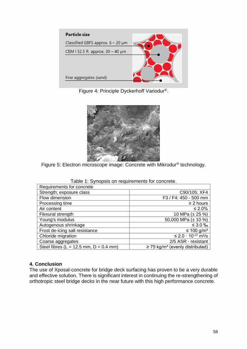
58
Figure 4: Principle Dyckerhoff Variodur®.
Figure 5: Electron microscope image: Concrete with Mikrodur® technology.
Table 1: Synopsis on requirements for concrete. Requirements for concrete
Strength; exposure class C90/105; XF4
Flow dimension F3 / F4: 450 - 500 mm
Processing time ≥ 2 hours
Air content ≤ 2.0%
Flexural strength 10 MPa (± 25 %)
Young's modulus 50,000 MPa (± 10 %)
Autogenous shrinkage ≤ 3.0 ‰
Frost de-icing salt resistance ≤ 100 g/m²
Chloride migration ≤ 2.0 · 10-12 m²/s
Coarse aggregates 2/5 ASR - resistant
Steel fibres (L = 12.5 mm, D = 0.4 mm) ≥ 75 kg/m³ (evenly distributed)
4. Conclusion The use of Xposal-concrete for bridge deck surfacing has proven to be a very durable and effective solution. There is significant interest in continuing the re-strengthening of orthotropic steel bridge decks in the near future with this high performance concrete.
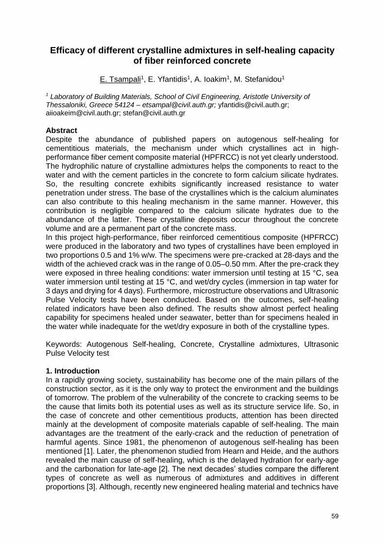
59
Efficacy of different crystalline admixtures in self-healing capacity of fiber reinforced concrete
E. Tsampali1, E. Yfantidis1, A. Ioakim1, M. Stefanidou1
1 Laboratory of Building Materials, School of Civil Engineering, Aristotle University of Thessaloniki, Greece 54124 – [email protected]; [email protected]; [email protected]; [email protected]
Abstract Despite the abundance of published papers on autogenous self-healing for cementitious materials, the mechanism under which crystallines act in high-performance fiber cement composite material (HPFRCC) is not yet clearly understood. The hydrophilic nature of crystalline admixtures helps the components to react to the water and with the cement particles in the concrete to form calcium silicate hydrates. So, the resulting concrete exhibits significantly increased resistance to water penetration under stress. The base of the crystallines which is the calcium aluminates can also contribute to this healing mechanism in the same manner. However, this contribution is negligible compared to the calcium silicate hydrates due to the abundance of the latter. These crystalline deposits occur throughout the concrete volume and are a permanent part of the concrete mass. In this project high-performance, fiber reinforced cementitious composite (HPFRCC) were produced in the laboratory and two types of crystallines have been employed in two proportions 0.5 and 1% w/w. The specimens were pre-cracked at 28-days and the width of the achieved crack was in the range of 0.05–0.50 mm. After the pre-crack they were exposed in three healing conditions: water immersion until testing at 15 °C, sea water immersion until testing at 15 °C, and wet/dry cycles (immersion in tap water for 3 days and drying for 4 days). Furthermore, microstructure observations and Ultrasonic Pulse Velocity tests have been conducted. Based on the outcomes, self-healing related indicators have been also defined. The results show almost perfect healing capability for specimens healed under seawater, better than for specimens healed in the water while inadequate for the wet/dry exposure in both of the crystalline types.
Keywords: Autogenous Self-healing, Concrete, Crystalline admixtures, Ultrasonic Pulse Velocity test 1. Introduction In a rapidly growing society, sustainability has become one of the main pillars of the construction sector, as it is the only way to protect the environment and the buildings of tomorrow. The problem of the vulnerability of the concrete to cracking seems to be the cause that limits both its potential uses as well as its structure service life. So, in the case of concrete and other cementitious products, attention has been directed mainly at the development of composite materials capable of self-healing. The main advantages are the treatment of the early-crack and the reduction of penetration of harmful agents. Since 1981, the phenomenon of autogenous self-healing has been mentioned [1]. Later, the phenomenon studied from Hearn and Heide, and the authors revealed the main cause of self-healing, which is the delayed hydration for early-age and the carbonation for late-age [2]. The next decades’ studies compare the different types of concrete as well as numerous of admixtures and additives in different proportions [3]. Although, recently new engineered healing material and technics have
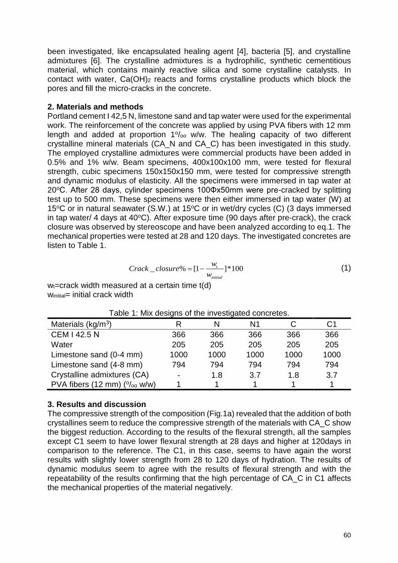
60
been investigated, like encapsulated healing agent [4], bacteria [5], and crystalline admixtures [6]. The crystalline admixtures is a hydrophilic, synthetic cementitious material, which contains mainly reactive silica and some crystalline catalysts. In contact with water, Ca(OH)2 reacts and forms crystalline products which block the pores and fill the micro-cracks in the concrete. 2. Materials and methods Portland cement I 42,5 N, limestone sand and tap water were used for the experimental work. The reinforcement of the concrete was applied by using PVA fibers with 12 mm length and added at proportion 1o/oo w/w. The healing capacity of two different crystalline mineral materials (CA_N and CA_C) has been investigated in this study. The employed crystalline admixtures were commercial products have been added in 0.5% and 1% w/w. Beam specimens, 400x100x100 mm, were tested for flexural strength, cubic specimens 150x150x150 mm, were tested for compressive strength and dynamic modulus of elasticity. All the specimens were immersed in tap water at 20oC. After 28 days, cylinder specimens 100Φx50mm were pre-cracked by splitting test up to 500 mm. These specimens were then either immersed in tap water (W) at 15oC or in natural seawater (S.W.) at 15oC or in wet/dry cycles (C) (3 days immersed in tap water/ 4 days at 40oC). After exposure time (90 days after pre-crack), the crack closure was observed by stereoscope and have been analyzed according to eq.1. The mechanical properties were tested at 28 and 120 days. The investigated concretes are listen to Table 1.
_ % [1 ]*100t
initial
wCrack closure
w (1)
wt=crack width measured at a certain time t(d) winitial= initial crack width
Table 1: Mix designs of the investigated concretes.
Materials (kg/m3) R N N1 C C1
CEM I 42.5 Ν 366 366 366 366 366
Water 205 205 205 205 205
Limestone sand (0-4 mm) 1000 1000 1000 1000 1000
Limestone sand (4-8 mm) 794 794 794 794 794
Crystalline admixtures (CA) - 1.8 3.7 1.8 3.7 PVA fibers (12 mm) (o/oo w/w) 1 1 1 1 1
3. Results and discussion The compressive strength of the composition (Fig.1a) revealed that the addition of both crystallines seem to reduce the compressive strength of the materials with CA_C show the biggest reduction. According to the results of the flexural strength, all the samples except C1 seem to have lower flexural strength at 28 days and higher at 120days in comparison to the reference. The C1, in this case, seems to have again the worst results with slightly lower strength from 28 to 120 days of hydration. The results of dynamic modulus seem to agree with the results of flexural strength and with the repeatability of the results confirming that the high percentage of CA_C in C1 affects the mechanical properties of the material negatively.
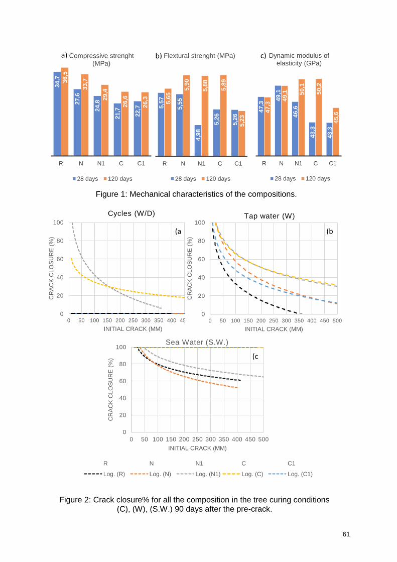
61
47
,3
49
,1
46
,6
43
,3
43
,3
47
,3
49
,1 50
,1
50
,2
45
,6
R N N1 C C1
Dynamic modulus of elasticity (GPa)
28 days 120 days
0
20
40
60
80
100
0 50 100 150 200 250 300 350 400 450 500
CR
AC
K C
LO
SU
RE
(%
)
INITIAL CRACK (MM)
Cycles (W/D)
Figure 1: Mechanical characteristics of the compositions.
0
20
40
60
80
100
0 50 100 150 200 250 300 350 400 450 500
CR
AC
K C
LO
SU
RE
(%
)
INITIAL CRACK (ΜM)
Tap water (W)
Figure 2: Crack closure% for all the composition in the tree curing conditions (C), (W), (S.W.) 90 days after the pre-crack.
a) b) c)
(a (b
(c
0
20
40
60
80
100
0 50 100 150 200 250 300 350 400 450 500
CR
AC
K C
LO
SU
RE
(%
)
INITIAL CRACK (ΜM)
Sea Water (S.W.)
R N N1 C C1
Log. (R) Log. (N) Log. (N1) Log. (C) Log. (C1)
34
,7
27
,6
24
,8
21
,7
22
,7
36
,5
33
,7
29
,4
26
,6
26
,3
R N N1 C C1
Compressive strenght (MPa)
28 days 120 days
5,5
7
5,5
5
4,9
8
5,2
6
5,2
6
5,6
5
5,9
0
5,8
8
5,8
9
5,2
3
R N N1 C C1
Flextural strenght (MPa)
28 days 120 days
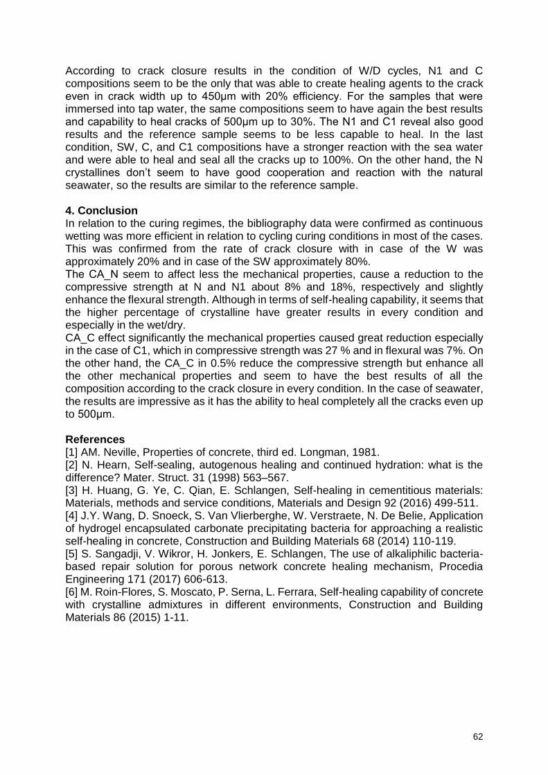
62
According to crack closure results in the condition of W/D cycles, N1 and C compositions seem to be the only that was able to create healing agents to the crack even in crack width up to 450μm with 20% efficiency. For the samples that were immersed into tap water, the same compositions seem to have again the best results and capability to heal cracks of 500μm up to 30%. The N1 and C1 reveal also good results and the reference sample seems to be less capable to heal. In the last condition, SW, C, and C1 compositions have a stronger reaction with the sea water and were able to heal and seal all the cracks up to 100%. On the other hand, the N crystallines don’t seem to have good cooperation and reaction with the natural seawater, so the results are similar to the reference sample. 4. Conclusion In relation to the curing regimes, the bibliography data were confirmed as continuous wetting was more efficient in relation to cycling curing conditions in most of the cases. This was confirmed from the rate of crack closure with in case of the W was approximately 20% and in case of the SW approximately 80%. The CA_Ν seem to affect less the mechanical properties, cause a reduction to the compressive strength at N and N1 about 8% and 18%, respectively and slightly enhance the flexural strength. Although in terms of self-healing capability, it seems that the higher percentage of crystalline have greater results in every condition and especially in the wet/dry. CA_C effect significantly the mechanical properties caused great reduction especially in the case of C1, which in compressive strength was 27 % and in flexural was 7%. On the other hand, the CA_C in 0.5% reduce the compressive strength but enhance all the other mechanical properties and seem to have the best results of all the composition according to the crack closure in every condition. In the case of seawater, the results are impressive as it has the ability to heal completely all the cracks even up to 500μm. References [1] AM. Neville, Properties of concrete, third ed. Longman, 1981. [2] N. Hearn, Self-sealing, autogenous healing and continued hydration: what is the difference? Mater. Struct. 31 (1998) 563–567. [3] H. Huang, G. Ye, C. Qian, E. Schlangen, Self-healing in cementitious materials: Materials, methods and service conditions, Materials and Design 92 (2016) 499-511. [4] J.Y. Wang, D. Snoeck, S. Van Vlierberghe, W. Verstraete, N. De Belie, Application of hydrogel encapsulated carbonate precipitating bacteria for approaching a realistic self-healing in concrete, Construction and Building Materials 68 (2014) 110-119. [5] S. Sangadji, V. Wikror, H. Jonkers, E. Schlangen, The use of alkaliphilic bacteria-based repair solution for porous network concrete healing mechanism, Procedia Engineering 171 (2017) 606-613. [6] M. Roin-Flores, S. Moscato, P. Serna, L. Ferrara, Self-healing capability of concrete with crystalline admixtures in different environments, Construction and Building Materials 86 (2015) 1-11.

63
Mitigating freeze/thaw damage to concrete through use of microencapsulated phase change materials
C. Romero Rodriguez1, E. Schlangen1, B. Šavija1
1 Microlab, Faculty of Civil Engineering and Geosciences, Delft University of Technology, Delft, the Netherlands - [email protected]; [email protected]; [email protected]
Abstract Concrete structures in cold climates may deteriorate due to frost action. Freezing and thawing cycles may cause significant damage to structures such as concrete pavements, retaining walls, and bridge decks. Cracks that occur cause rapid pathways for ingress of aggressive substances such as carbon dioxide and chloride. Traditionally, freeze/thaw resistance of concrete has been controlled through the use of air-entraining agents. However, air entrainment has a practical drawback: the process may be influenced by the temperature, cement chemistry, presence of SCMs, and on-site factors. Recently, a new approach has been put forward: use of phase change materials (PCMs) in concrete mixtures to keep the material warm and thus reduce the actual number of freeze/thaw cycles that it undergoes. It is expected that concrete incorporating properly designed phase change materials in appropriate doses will be able to remain warm longer, thereby reducing the number of freeze/thaw cycles and consequently the damage. This work explores the use of microencapsulated PCMs for reducing damage to freeze/thaw and frost salt scaling. Mortars with varying amounts of PCMs have been cast and exposed to freezing and thawing cycles. Their damage has been monitored non-destructively by using X-ray computed tomography. Furthermore, the influence of PCM addition on mechanical and transport properties of mortars has been assessed. Based on the results of this study, insights into freeze/thaw resistance of cementitious materials with PCM addition have been obtained. These findings will provide a basis for future research and possible practical application of the technology. 1. Introduction Freeze/thaw damage is a common deterioration mechanism affecting concrete structures in temperate climates. A common way of preventing damage is through the use of air entraining admixtures, which create air voids which can accommodate expansive pressures caused by ice formation. The Use of air entraining agents, however, can be problematic in practical conditions, and it is difficult to ensure its functionality. In recent years, another approach has been put forward: use of microencapsulated phase change materials (PCMs) in concrete mixtures [1]. A phase change material (PCM) is a substance with a high heat of fusion which, melting and solidifying at a certain temperature, is capable of storing and releasing large amounts of energy [2]. Some PCMs solidify close to 0 °C, releasing latent heat to the surrounding concrete. This way, the concrete stays warm longer, and in theory will undergo a lower number of f/t cycles. This should, in theory, lead to lower deterioration [3]. On the other hand, it is known that incorporation of microencapsulated PCMs in concrete leads to a decrease in its strength. Therefore, the resulting damage will depend on two opposing influences: on the one hand, concrete with PCM addition will suffer lower stresses due to less cooling; on the other hand, it will have a lower strength and could still crack. Therefore, this study focused on quantifying the damage
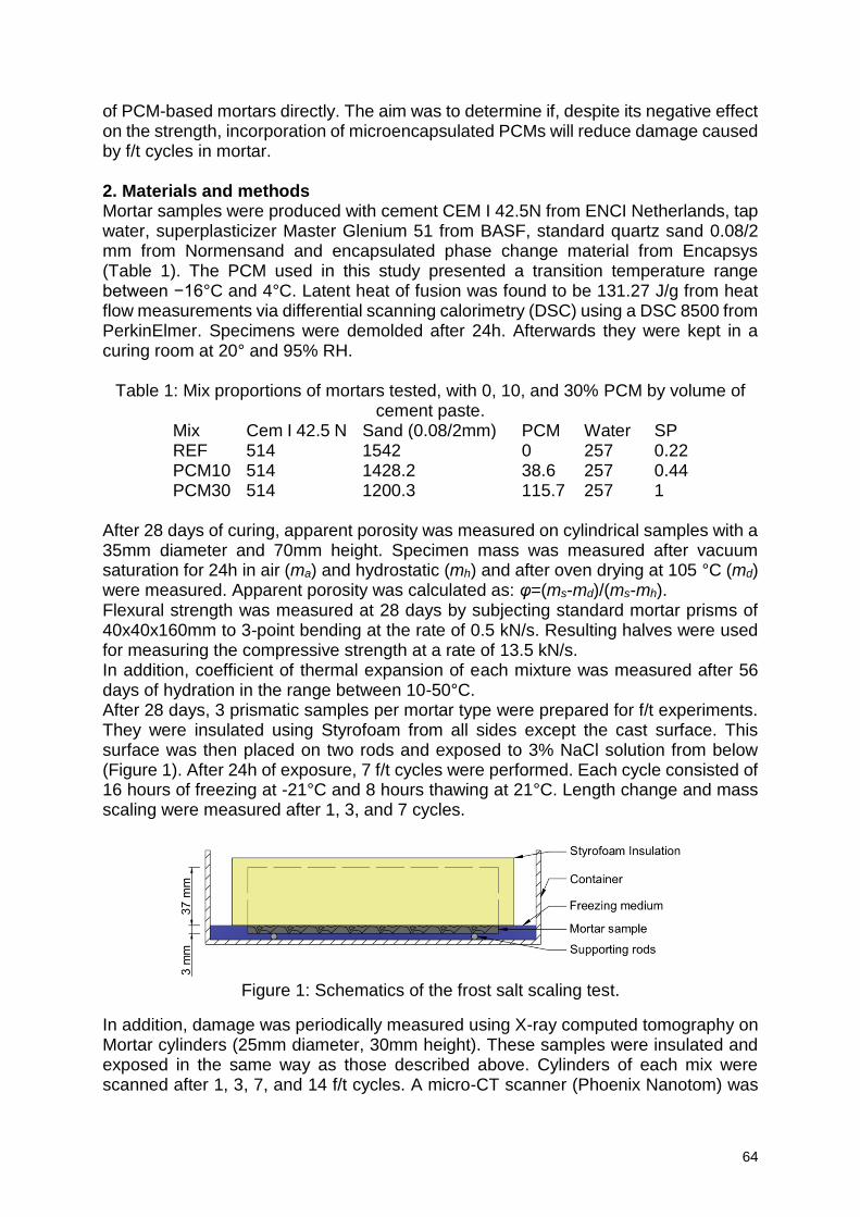
64
of PCM-based mortars directly. The aim was to determine if, despite its negative effect on the strength, incorporation of microencapsulated PCMs will reduce damage caused by f/t cycles in mortar. 2. Materials and methods Mortar samples were produced with cement CEM I 42.5N from ENCI Netherlands, tap water, superplasticizer Master Glenium 51 from BASF, standard quartz sand 0.08/2 mm from Normensand and encapsulated phase change material from Encapsys (Table 1). The PCM used in this study presented a transition temperature range between −16°C and 4°C. Latent heat of fusion was found to be 131.27 J/g from heat flow measurements via differential scanning calorimetry (DSC) using a DSC 8500 from PerkinElmer. Specimens were demolded after 24h. Afterwards they were kept in a curing room at 20° and 95% RH.
Table 1: Mix proportions of mortars tested, with 0, 10, and 30% PCM by volume of cement paste.
Mix Cem I 42.5 N Sand (0.08/2mm) PCM Water SP REF 514 1542 0 257 0.22 PCM10 514 1428.2 38.6 257 0.44 PCM30 514 1200.3 115.7 257 1
After 28 days of curing, apparent porosity was measured on cylindrical samples with a 35mm diameter and 70mm height. Specimen mass was measured after vacuum saturation for 24h in air (ma) and hydrostatic (mh) and after oven drying at 105 °C (md) were measured. Apparent porosity was calculated as: φ=(ms-md)/(ms-mh). Flexural strength was measured at 28 days by subjecting standard mortar prisms of 40x40x160mm to 3-point bending at the rate of 0.5 kN/s. Resulting halves were used for measuring the compressive strength at a rate of 13.5 kN/s. In addition, coefficient of thermal expansion of each mixture was measured after 56 days of hydration in the range between 10-50°C. After 28 days, 3 prismatic samples per mortar type were prepared for f/t experiments. They were insulated using Styrofoam from all sides except the cast surface. This surface was then placed on two rods and exposed to 3% NaCl solution from below (Figure 1). After 24h of exposure, 7 f/t cycles were performed. Each cycle consisted of 16 hours of freezing at -21°C and 8 hours thawing at 21°C. Length change and mass scaling were measured after 1, 3, and 7 cycles.
Figure 1: Schematics of the frost salt scaling test.
In addition, damage was periodically measured using X-ray computed tomography on Mortar cylinders (25mm diameter, 30mm height). These samples were insulated and exposed in the same way as those described above. Cylinders of each mix were scanned after 1, 3, 7, and 14 f/t cycles. A micro-CT scanner (Phoenix Nanotom) was
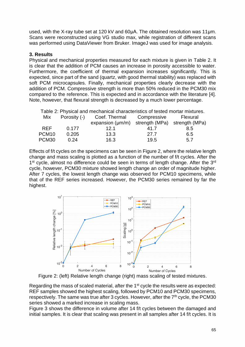
65
used, with the X-ray tube set at 120 kV and 60μA. The obtained resolution was 11μm. Scans were reconstructed using VG studio max, while registration of different scans was performed using DataViewer from Bruker. ImageJ was used for image analysis. 3. Results Physical and mechanical properties measured for each mixture is given in Table 2. It is clear that the addition of PCM causes an increase in porosity accessible to water. Furthermore, the coefficient of thermal expansion increases significantly. This is expected, since part of the sand (quartz, with good thermal stability) was replaced with soft PCM microcapsules. Finally, mechanical properties clearly decrease with the addition of PCM. Compressive strength is more than 50% reduced in the PCM30 mix compared to the reference. This is expected and in accordance with the literature [4]. Note, however, that flexural strength is decreased by a much lower percentage.
Table 2: Physical and mechanical characteristics of tested mortar mixtures. Mix Porosity (-) Coef. Thermal
expansion (μm/m) Compressive
strength (MPa) Flexural
strength (MPa) REF 0.177 12.1 41.7 8.5
PCM10 0.205 13.3 27.7 6.5 PCM30 0.24 16.3 19.5 5.7
Effects of f/t cycles on the specimens can be seen in Figure 2, where the relative length change and mass scaling is plotted as a function of the number of f/t cycles. After the 1st cycle, almost no difference could be seen in terms of length change. After the 3rd cycle, however, PCM30 mixture showed length change an order of magnitude higher. After 7 cycles, the lowest length change was observed for PCM10 specimens, while that of the REF series increased. However, the PCM30 series remained by far the highest.
Figure 2: (left) Relative length change (right) mass scaling of tested mixtures.
Regarding the mass of scaled material, after the 1st cycle the results were as expected: REF samples showed the highest scaling, followed by PCM10 and PCM30 specimens, respectively. The same was true after 3 cycles. However, after the 7th cycle, the PCM30 series showed a marked increase in scaling mass. Figure 3 shows the difference in volume after 14 f/t cycles between the damaged and initial samples. It is clear that scaling was present in all samples after 14 f/t cycles. It is
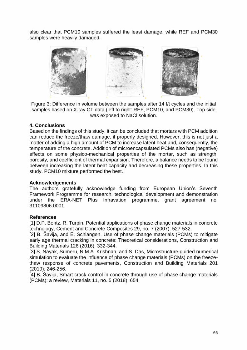
66
also clear that PCM10 samples suffered the least damage, while REF and PCM30 samples were heavily damaged.
Figure 3: Difference in volume between the samples after 14 f/t cycles and the initial samples based on X-ray CT data (left to right: REF, PCM10, and PCM30). Top side
was exposed to NaCl solution.
4. Conclusions Based on the findings of this study, it can be concluded that mortars with PCM addition can reduce the freeze/thaw damage, if properly designed. However, this is not just a matter of adding a high amount of PCM to increase latent heat and, consequently, the temperature of the concrete. Addition of microencapsulated PCMs also has (negative) effects on some physico-mechanical properties of the mortar, such as strength, porosity, and coefficient of thermal expansion. Therefore, a balance needs to be found between increasing the latent heat capacity and decreasing these properties. In this study, PCM10 mixture performed the best. Acknowledgements The authors gratefully acknowledge funding from European Union’s Seventh Framework Programme for research, technological development and demonstration under the ERA-NET Plus Infravation programme, grant agreement no: 31109806.0001. References [1] D.P. Bentz, R. Turpin, Potential applications of phase change materials in concrete technology, Cement and Concrete Composites 29, no. 7 (2007): 527-532. [2] B. Šavija, and E. Schlangen, Use of phase change materials (PCMs) to mitigate early age thermal cracking in concrete: Theoretical considerations, Construction and Building Materials 126 (2016): 332-344. [3] S. Nayak, Sumeru, N.M.A. Krishnan, and S. Das, Microstructure-guided numerical simulation to evaluate the influence of phase change materials (PCMs) on the freeze-thaw response of concrete pavements, Construction and Building Materials 201 (2019): 246-256. [4] B. Šavija, Smart crack control in concrete through use of phase change materials (PCMs): a review, Materials 11, no. 5 (2018): 654.
67
Analysis of the compressive fatigue loading of ultra-high strength grouts and influence of the aggregate nature on the fatigue life
E. Myrtja1, J. Soudier2, E. Prat2 and M. Chaouche1
1 Laboratoire de Mécanique et Technologie LMT, ENS Cachan, CNRS, Université Paris-Saclay, 61 Avenue du Président Wilson, 94230, Cachan, France – [email protected] ; [email protected] 2 Centre d’Innovation Parexgroup, 103-105 rue de Santoyon, 38070, Saint-Quentin-Fallavier, France – [email protected] ; [email protected]
Abstract Recent modern constructions such as wind turbines require higher performances of concrete and grout, while being submitted to continuous cyclic loading during their service life. Thus, the fatigue behavior of these materials is a key factor to be analyzed and studied further. However, relatively few studies are available about fatigue behavior of ultra-high strength concrete and grout, and they often are contradictory. A series of monotonic and fatigue tests were performed to investigate the fatigue behavior of ultra-high strength grout under compression. Multiple stress levels were tested at two loading frequencies, 10Hz and 1Hz. At a higher frequency the specimens showed some heating, which can be up to 30K compared to the initial temperature and it can influence the fatigue life. Further testing showed that the heating source is the heating released by the friction between the micro-cracks. Furthermore, the influence of the aggregate nature between two aggregates on the fatigue strength was studied by analyzing the number of cycles to failure, strain development and the temperature increase.
Keywords: Fatigue, high-strength grout, strain, damage, temperature 1. Introduction High-strength grouts have recently gained further interest due to applications in sleeker structures such as wind turbines or road joints, both submitted to fatigue loading due to wind and wave loads. Design methods such as CEB-FIP 2010 [1] and Det Norske Veritas [2] are used to describe the fatigue behavior, respectively in concrete and grout and are based on the Wöhler S-N curves. However, limited studies are available for fatigue in concrete [3–5], but even fewer research is found for fatigue behavior of grout and high-strength grout [6]. This research is focused on the low cycle compressive fatigue behavior of three high strength grout mixes by analyzing the aggregate influence on the fatigue life. Some studies [3,7,8] showed that the grain composition has no influence on the fatigue life, but they mostly involved the grain size. Other studies [9,10] focusing on the influence of the aggregate nature, showed that its effect on the fatigue life is significant. Moreover, the strain development and the temperature increase are also analyzed. Very few studies observe a temperature increase in concrete or grout during fatigue [6,11] and suppose the origin of this phenomenon as the friction between micro cracks. Nevertheless, no verification of this hypothesis was found in literature. The last part of this research study will show a simple experimental method in order to prove this theory.
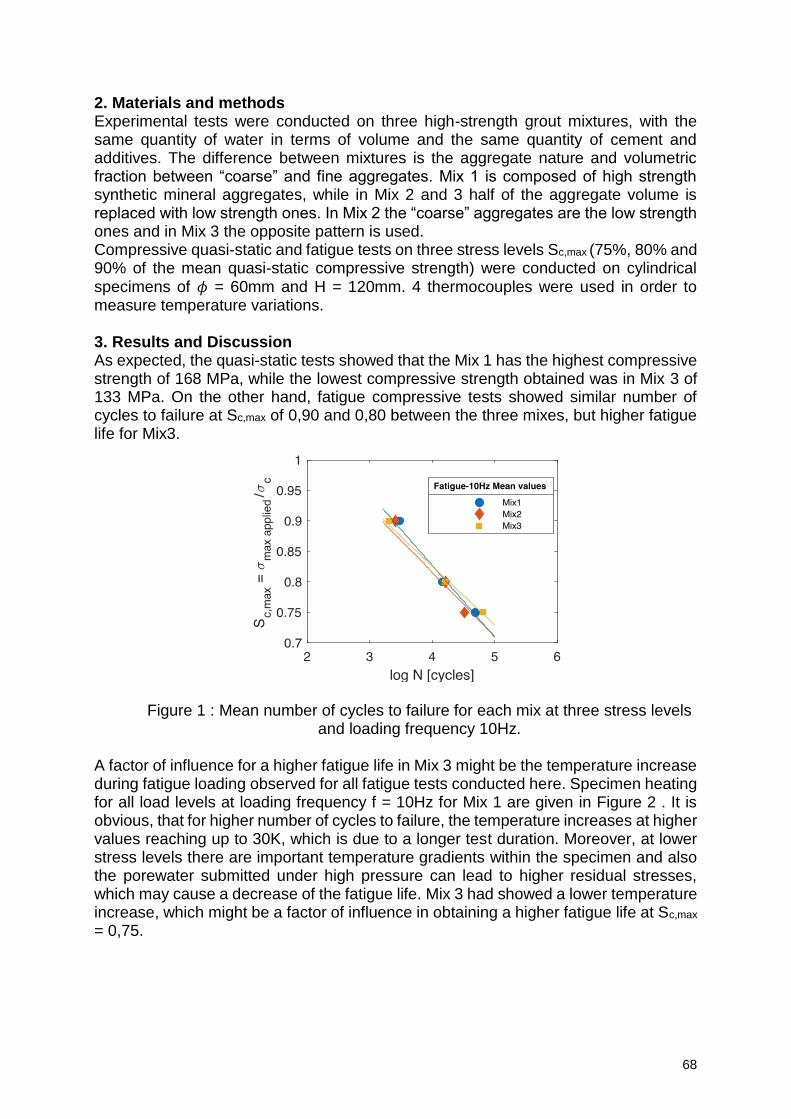
68
2. Materials and methods Experimental tests were conducted on three high-strength grout mixtures, with the same quantity of water in terms of volume and the same quantity of cement and additives. The difference between mixtures is the aggregate nature and volumetric fraction between “coarse” and fine aggregates. Mix 1 is composed of high strength synthetic mineral aggregates, while in Mix 2 and 3 half of the aggregate volume is replaced with low strength ones. In Mix 2 the “coarse” aggregates are the low strength ones and in Mix 3 the opposite pattern is used. Compressive quasi-static and fatigue tests on three stress levels Sc,max (75%, 80% and 90% of the mean quasi-static compressive strength) were conducted on cylindrical specimens of 𝜙 = 60mm and H = 120mm. 4 thermocouples were used in order to measure temperature variations. 3. Results and Discussion As expected, the quasi-static tests showed that the Mix 1 has the highest compressive strength of 168 MPa, while the lowest compressive strength obtained was in Mix 3 of 133 MPa. On the other hand, fatigue compressive tests showed similar number of cycles to failure at Sc,max of 0,90 and 0,80 between the three mixes, but higher fatigue life for Mix3.
Figure 1 : Mean number of cycles to failure for each mix at three stress levels and loading frequency 10Hz.
A factor of influence for a higher fatigue life in Mix 3 might be the temperature increase during fatigue loading observed for all fatigue tests conducted here. Specimen heating for all load levels at loading frequency f = 10Hz for Mix 1 are given in Figure 2 . It is obvious, that for higher number of cycles to failure, the temperature increases at higher values reaching up to 30K, which is due to a longer test duration. Moreover, at lower stress levels there are important temperature gradients within the specimen and also the porewater submitted under high pressure can lead to higher residual stresses, which may cause a decrease of the fatigue life. Mix 3 had showed a lower temperature increase, which might be a factor of influence in obtaining a higher fatigue life at Sc,max
= 0,75.
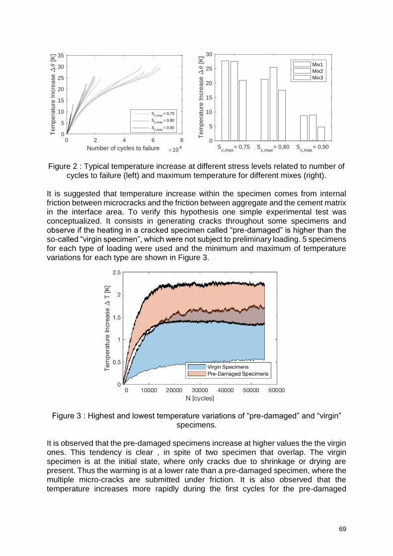
69
Figure 2 : Typical temperature increase at different stress levels related to number of
cycles to failure (left) and maximum temperature for different mixes (right). It is suggested that temperature increase within the specimen comes from internal friction between microcracks and the friction between aggregate and the cement matrix in the interface area. To verify this hypothesis one simple experimental test was conceptualized. It consists in generating cracks throughout some specimens and observe if the heating in a cracked specimen called “pre-damaged” is higher than the so-called “virgin specimen”, which were not subject to preliminary loading. 5 specimens for each type of loading were used and the minimum and maximum of temperature variations for each type are shown in Figure 3.
Figure 3 : Highest and lowest temperature variations of “pre-damaged” and “virgin” specimens.
It is observed that the pre-damaged specimens increase at higher values the the virgin ones. This tendency is clear , in spite of two specimen that overlap. The virgin specimen is at the initial state, where only cracks due to shrinkage or drying are present. Thus the warming is at a lower rate than a pre-damaged specimen, where the multiple micro-cracks are submitted under friction. It is also observed that the temperature increases more rapidly during the first cycles for the pre-damaged
0 2 4 6 8
Number of cycles to failure 104
0
5
10
15
20
25
30
35T
em
pe
ratu
re In
cre
ase
[K
]
Sc,max
= 0,75
Sc,max
= 0,80
Sc,max
= 0,90
Sc,max
= 0,75 Sc,max
= 0,80 Sc,max
= 0,900
5
10
15
20
25
30
Tem
pe
ratu
re In
cre
ase
[K
]
Mix1
Mix2
Mix3
70
specimen. This is also due to the micro-cracks which are aleady present and thus more heating is released at the beginning of the testing. 4. Conclusions Experimental testing conducted in this study showed that the aggregate nature has an influence on the fatigue life of high-strength grouts. Moreover, significant temperature elevations have been observed, which may lead to lower number of cycles to failure for lower stress levels. Finally, the origin of this temperature increase was shown to be manifested by the friction between microcracks, where the specimens with a more dense cracked volume reached higher temperature elevations. References [1] CEB-FIP, Model Code 2010 : Fatigue of concrete structures : State of the art report. [2] DNV, Offshore Standard: Design of Offshore Wind Turbine Structures, 2014. [3] L. Lohaus, N. Oneschkow, M. Wefer, Design model for the fatigue behaviour of normal-strength, high-strength and ultra-high-strength concrete, Struct. Concr. 13 (2012). [4] N. Oneschkow, Fatigue behaviour of high-strength concrete with respect to strain and stiffness, Int. J. Fatigue. 87 (2016) 38–49. [5] M.-T. Do, O. Chaallal, P.-C. Aïtcin, Fatigue behavior of High Performance Concrete, J. Mater. Civ. Eng. 5 (1993) 96–111. [6] K. Elsmeier, J. Hümme, N. Oneschkow, L. Lohaus, Prüftechnische Einflüsse auf das Ermüdungsverhalten hochfester feinkörniger Vergussbetone, Beton- Und Stahlbetonbau. 111 (2016) 233–240. [7] Hordijk D.A. & Wolsink G.M. & de Vries, Fracture and fatigue behaviour of a high strength limestone concrete as compared to gravel concrete, HERON. 40 (1995). [8] E.W. Bennett, Some fatigue tests of high-strength concrete in axial compression, Mag. Concr. Res. 19 (1967) 113–117. [9] M.A. Farooq, Y. Sato, T. Ayano, K. Niitani, Experimental and numerical investigation of static and fatigue behavior of mortar with blast furnace slag sand as fine aggregates in air and water, Constr. Build. Mater. 143 (2017) 429–443. [10] J.-K. Kim, Y.-Y. Kim, Experimental Study of the fatigue behavior of High Strength Concrete, Cem. Concr. Res. 26 (1996) 1513–1523. [11] J. Hümme, C. von der Haar, L. Lohaus, S. Marx, Fatigue behaviour of a normal-strength concrete - number of cycles to failure and strain development, Struct. Concr. (2015).
71
Mechanism Analysis of Calcium Sulfoaluminate Cement Resistance to Sulfate Attack
W.Hou1, ZQ.Liu1, FQ.He2
1 School of Civil Engineering, Central South University, Tianxin district ,410075, Changsha,
China,[email protected]
2 School of Civil Engineering and Architecture, Xiamen University of Technology, Jimei district ,361024,Xiamen, China, [email protected]
Abstract Compared with portland cement, calcium sulfoaluminate cement nowadays has been gradually applied in many construction projects due to its advantages such as short setting time, high early strength and low energy consumption. Current research suggests that sulfate resistance of calcium sulfoaluminate cement is mainly because of the absence of calcium hydroxide in its hydration products and the dense pore structure of the specimen. In this paper, further analysis was made from the perspective of ion migration and chemical equilibrium. The specimens were immersed in sodium sulfate solution with 10% mass fraction until specified immersion time (60 and 240 days) reached. Result showed that the content of SO4
2- in specimen was almost equal to the initial value and the concentration of sulfate ion in the pore solution was very close to the external immersion solution at 60 days. At the meantime, the content of Na+ increased while the content of K+ and Ca2+ declined. Besides, Na+ in the external immerse solution was exchanged with the cation inside the specimen, such as K+, Ca2+, and Mg2+, and which was verified by X-ray diffraction test and charge balance calculation. So the insoluble sulfate in the specimen was converted into soluble sulfate, which raised the concentration of sulfate in the pore solution. With the drops of concentration gradient between the pore solution and the immersion solution, it was difficult for the external sulfate to migrate into the inside of the specimen. As a result, the specimens has an enhanced resistance to sulfate attack.
Keywords: Anhydrite dissolve; Concentration gradient; Charge balance
1. Introduction Today, the durability and service life prediction of concrete structures have become hot issues in the field of construction engineering. When sulfate ions penetrate into ordinary portland cement and concrete facilities, it will cause durability problems like expansion and cracking. Therefore, it is urgent to find a new kind of cementitious material which is suitable for construction projects in Salt Lake area with high strength and durability. In the 1970s[1],China had developed Sulfoaluminate cement (SAC) with higher hydration speed and early strength and better corrosion resistance than those of ordinary Portland cement, which led to sulfoaluminate cement had been adopted and popularized in more and more construction projects, ocean projects, emergency repair seepage control projects and so on. Furthermore, the durability still had been paid more attention. Current research on sulfate resistance of Sulfoaluminate cement mainly focuses on concrete shrinkage, mass loss, and strength loss etc. Many researchers believe that above situation is due to the absence of calcium hydroxide in its hydration products of calcium Sulfoaluminate cement and the dense pore structure of the specimen,
72
however, none of them explains why SAC is sulfate resistant to sulfate attack in mechanisms. In order to find out the real reason why SAC can resist sulfate attack, the ion concentration in the pore solution of the specimen immersed in Na2SO4 solution was analyzed, the powder was taken by layer and dissolved. Ion chromatograph, atomic fluorescence spectrophotometer and inductively coupled plasma were used to measure the anions and cations in the filtrate of dissolved samples. Ion exchange, charge balance, hydrated ion radius and hydration free energy[2] were considered in the experiment and the XRD instrument was used to measure the changes of phase content and composition. 2. Materials and methods Research adopted raw materials as followed: (a) 42.5 grade rapid hardening
sulfoaluminate cement(SAC);(b) sodium sulfate was pure anhydrous for analysis;
(c) melamine powder was chosen as superplasticizer. (d) deionized water, the
resistivity was no less than 18.0 MΩ·cm。
Preparations of specimens could be described as followed. Mortar specimens with 0.3 water to cement ratio (adding melamine powder with a cement quality of 1.0% in aqueous solution), 0.4 and 0.5, and paste specimens with 0.4 water to cement ratios were prepared respectively. Mass ratio of cement to sand was 1:2 for mortar samples. The fresh mixture was casted into a cylindrical mold of Ф100mm×100mm, placed on the shaking table for 10 seconds and smoothed the specimen surface, then the surface was covered with a plastic film to prevent water evaporation. All specimens were firstly
cured in laboratory environment (20±2,RH=65±5%) for 6 hours then demolded and
maintained in a standard curing room (20±2, RH> 95%) for 14 days. The central
portions of cylindrical cores(Ф100 mm×50 mm) were cut for tests. Specimens firstly dried in laboratory environment for 24 hours and then was coated with a layer of epoxy resin on the cylindrical surface (not the upper and lower surfaces) for 24 h for solidifying completely. Secondly, specimens were placed in a vacuum water saturated machine for saturation treatment[3].The water saturation parameters were set as followed: 8 h for vacuuming, 6 h for water injection and continuedly vacuuming, 33.5 h for returning to normal pressure, and 0.5 h for excluding water. Thirdly, specimens were wiped with a wet towel to a saturated surface state, and then placed
in sodium sulfate solution with 10% mass fraction (20±2). Replaced the sodium
sulfate solution after 60 days immersed, then no longer to replace more. Pore solutions of specimens were extracted by expression method when the
specimens were immersed until test age. At the same time, fresh sliced paste specimens were polished and analyzed by X-ray diffraction. Then Use the numerical control lathe to take powder layer by layer. Ground the dried powder to a particle size
less than 250 m, then dissolved with the method of hydrochloric acid. The colatuie was diluted to a certain multiple to measure the concentration of anions and cations.
3. Results and discussion After eroding for 60 and 240days, the distributions of sulfate ion concentration in three sets of specimens were shown in Figure 1.The concentration of sulfate ion in specimens with low water cement ratio (M0.3, M0.4) was equivalent to the initial values at different distance from the surface to the interior, sulfate ion had not yet penetrated into the interior. However, the concentration of sulfate ion in mortar specimens with water cement ratio of 0.5(M0.5) was slightly higher than the initial value at the distances of 1 to 3 mm from the surface. When specimens had been immersed for 240 days, the
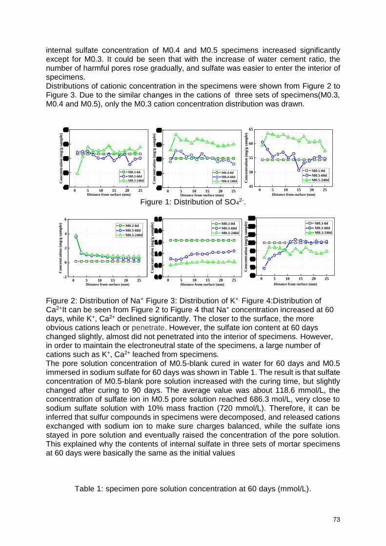
73
internal sulfate concentration of M0.4 and M0.5 specimens increased significantly except for M0.3. It could be seen that with the increase of water cement ratio, the number of harmful pores rose gradually, and sulfate was easier to enter the interior of specimens. Distributions of cationic concentration in the specimens were shown from Figure 2 to Figure 3. Due to the similar changes in the cations of three sets of specimens(M0.3, M0.4 and M0.5), only the M0.3 cation concentration distribution was drawn.
Figure 1: Distribution of SO4
2-.
Figure 2: Distribution of Na+ Figure 3: Distribution of K+. Figure 4:Distribution of Ca2+It can be seen from Figure 2 to Figure 4 that Na+ concentration increased at 60 days, while K+, Ca2+ declined significantly. The closer to the surface, the more obvious cations leach or penetrate. However, the sulfate ion content at 60 days changed slightly, almost did not penetrated into the interior of specimens. However, in order to maintain the electroneutral state of the specimens, a large number of cations such as K+, Ca2+ leached from specimens. The pore solution concentration of M0.5-blank cured in water for 60 days and M0.5 immersed in sodium sulfate for 60 days was shown in Table 1. The result is that sulfate concentration of M0.5-blank pore solution increased with the curing time, but slightly changed after curing to 90 days. The average value was about 118.6 mmol/L, the concentration of sulfate ion in M0.5 pore solution reached 686.3 mol/L, very close to sodium sulfate solution with 10% mass fraction (720 mmol/L). Therefore, it can be inferred that sulfur compounds in specimens were decomposed, and released cations exchanged with sodium ion to make sure charges balanced, while the sulfate ions stayed in pore solution and eventually raised the concentration of the pore solution. This explained why the contents of internal sulfate in three sets of mortar specimens at 60 days were basically the same as the initial values
Table 1: specimen pore solution concentration at 60 days (mmol/L).
0 5 10 15 20 2545
50
55
60
65
Con
cen
trati
on
(m
g/g
sam
ple
)
Distance from surface (mm)
M0.3-0d
M0.3-60d
M0.3-240d
0 5 10 15 20 2545
50
55
60
65
Co
nce
ntr
ati
on
(m
g/g
sa
mp
le)
Distance from surface (mm)
M0.4-0d
M0.4-60d
M0.4-240d
0 5 10 15 20 2545
50
55
60
65
Con
cen
trati
on
(m
g/g
sam
ple
)
Distance from surface (mm)
M0.5-0d
M0.5-60d
M0.5-240d
0 5 10 15 20 25-2
0
2
4
6
Con
cen
tra
tion
(m
g/g
sam
ple
)
Distance from surface (mm)
M0.3-0d
M0.3-60d
M0.3-240d
0 5 10 15 20 250.0
0.5
1.0
1.5
2.0
2.5
Con
cen
trati
on
(m
g/g
sam
ple
)
Distance from surface (mm)
M0.3-0d
M0.3-60d
M0.3-240d
0 5 10 15 20 2560
70
80
90
100
110
120
130
Co
nce
ntr
ati
on
(m
g/g
sa
mp
le)
Distance from surface (mm)
M0.3-0d
M0.3-60d
M0.3-240d
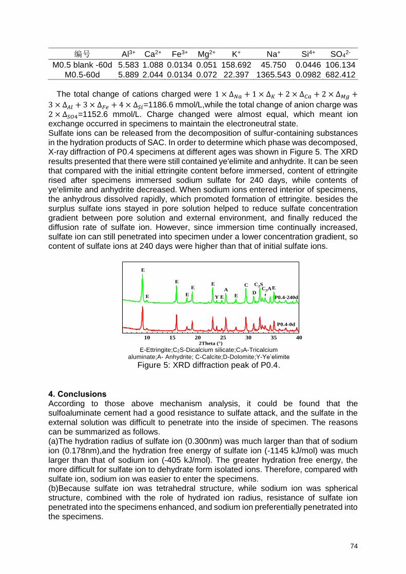
74
编号 Al3+ Ca2+ Fe3+ Mg2+ K+ Na+ Si4+ SO42-
M0.5 blank -60d 5.583 1.088 0.0134 0.051 158.692 45.750 0.0446 106.134
M0.5-60d 5.889 2.044 0.0134 0.072 22.397 1365.543 0.0982 682.412
The total change of cations charged were 1 × ∆𝑁𝑎 + 1 × ∆𝐾 + 2 × ∆𝐶𝑎 + 2 × ∆𝑀𝑔 +
3 × ∆𝐴𝑙 + 3 × ∆𝐹𝑒 + 4 × ∆𝑆𝑖=1186.6 mmol/L,while the total change of anion charge was 2 × ∆𝑆𝑂4=1152.6 mmol/L. Charge changed were almost equal, which meant ion exchange occurred in specimens to maintain the electroneutral state. Sulfate ions can be released from the decomposition of sulfur-containing substances in the hydration products of SAC. In order to determine which phase was decomposed, X-ray diffraction of P0.4 specimens at different ages was shown in Figure 5. The XRD results presented that there were still contained ye'elimite and anhydrite. It can be seen that compared with the initial ettringite content before immersed, content of ettringite rised after specimens immersed sodium sulfate for 240 days, while contents of ye'elimite and anhydrite decreased. When sodium ions entered interior of specimens, the anhydrous dissolved rapidly, which promoted formation of ettringite. besides the surplus sulfate ions stayed in pore solution helped to reduce sulfate concentration gradient between pore solution and external environment, and finally reduced the diffusion rate of sulfate ion. However, since immersion time continually increased, sulfate ion can still penetrated into specimen under a lower concentration gradient, so content of sulfate ions at 240 days were higher than that of initial sulfate ions.
4. Conclusions According to those above mechanism analysis, it could be found that the sulfoaluminate cement had a good resistance to sulfate attack, and the sulfate in the external solution was difficult to penetrate into the inside of specimen. The reasons can be summarized as follows. (a)The hydration radius of sulfate ion (0.300nm) was much larger than that of sodium ion (0.178nm),and the hydration free energy of sulfate ion (-1145 kJ/mol) was much larger than that of sodium ion (-405 kJ/mol). The greater hydration free energy, the more difficult for sulfate ion to dehydrate form isolated ions. Therefore, compared with sulfate ion, sodium ion was easier to enter the specimens. (b)Because sulfate ion was tetrahedral structure, while sodium ion was spherical structure, combined with the role of hydrated ion radius, resistance of sulfate ion penetrated into the specimens enhanced, and sodium ion preferentially penetrated into the specimens.
E-Ettringite;C2S-Dicalcium silicate;C3A-Tricalcium aluminate;A- Anhydrite; C-Calcite;D-Dolomite;Y-Ye’elimite
Figure 5: XRD diffraction peak of P0.4.
10 15 20 25 30 35 40
E
2Theta (°)
P0.4-240d
C3A
P0.4-0d
C2S
Y
C
DA
E
E
E
E
E
E
EE
75
(c)The hydration products of SAC still contained anhydrite and ye'elimite, when sodium ion penetrated into specimens, anhydrite decomposed rapidly and released Ca2+ and SO4
2-. Some of the dissolved anhydrite reacts with ye'elimite to form ettringite which made the structure become more compact. Besides another part of Ca2+ dissolved and exchanged with Na+, while SO4
2-stayed in pore solution as a free state, which raised the pore solution concentration, reduced the concentration gradient between pore solution and the external erosion environment of the specimens. Finally reduced the diffusion driving force, therefore the resistance to sulfate attack of SAC had been enhanced. Acknowledgments Financial support from the National Natural Science Foundation of China (No. 51378508 and 51858783) are greatly appreciated. References
[1] Muzhen.Su,Yanmou.Wang,Liang.Zhang The Sulfoaluminate Cement [M]. Beijing:
Beijing University of Technology publisher, 1999.
[2] Tansel,Berrin. Significance of thermodynamic and physical characteristics on
permeation of ions during membrane separation: Hydrated radius, hydration free energy and viscous effects[J]. Separation & Purification Technology, 2012, 86(8): 119-126. [3] NTBuild492.Concrete,mortar and cement-based repair materials:Chloride migration coefficient from non-steady-state migration experiments,Nordtest method,1999.
76
Durability of Acrylic Latex and Silica Fume Modified Cement Mortar under Harsh Circumstances
Sukanta Kumer Shill1, Safat Al-Deen1, Mahmud Ashraf2
1School of engineering and information technology, the University of New South Wales, Canberra, Australia [email protected]; [email protected] 2School of Engineering, Deakin University, Waurn Ponds Campus, VIC 3216, Australia - [email protected]
Abstract Acrylic latex (AL) is a polymer that is often used in resurfacing as a thin layer coating on the degraded surface of concrete structures. The study presented in this paper aims to investigate the suitability of using AL and silica fume (SF) modified Portland cement (PC) mortar to repair the scaled concrete at military airbases’ apron those are regularly exposed to high thermal cycles and is often found saturated by the aviation oils. For this purpose, PC mortar was modified by 15% of AL (by parts) and was replaced by 10% of SF, and the performance of the modified mortar was experimentally investigated. Both the unmodified original PC mortar and the modified PC mortar was repeatedly exposed to both the aviation oils and high thermal cycles simultaneously, until the scale formation on the surface of the mortar. During the experimental investigation, the compressive strength degradation and loss of mass of the mortar were recorded. Chemical analyses of the mortar and aviation oils are also conducted. The study reveals that AL and SF modified PC mortar is more durable than the unmodified conventional PC mortar under army airbase circumstances.
Keywords: Compressive strength, durability, chemical damage, high thermal cycles 1. Introduction In the construction industry, the water-based AL has been used in hydraulic cement for modifying a few specific properties of concrete for more than 50 years with excellent success [1]. AL is defined as a family of polymers resulting from the polymerisation of derivatives of acrylic and methacrylic acids [2]. AL modified cement mortar is often used to repair a small to large area of the old worn concrete surface. It is primarily preferred for thin coatings and patching for concrete restoration as well as an overlay on the surface of the degraded concrete [1, 2]. As reported, the acrylic (methacrylate) polymers are used to seal the surface cracks and joints of the airfield concrete in Australia [3].
AL is considered as one of the principal latexes used for the production of polymer modified concrete and mortar [4]. It improves the flexural strength, tensile strength, impact strength, abrasion resistance, resistance to permeability, chemical resistance and adhesion of hydraulic cement mortar [1, 2, 5-7]. Furthermore, AL modified PC overlay for repairing of industrial and commercial floor performs better than the unmodified mortar when they are exposed to adverse conditions [2]. AL is also recognised for their high durability, freeze-thaw resistance and they are not commonly susceptible to hydrolysis.
Based on a review of the literature, Shill et al. [8, 9] stated that AL and SF modified cementitious mortar could be a promising alternative to conventional PC mortar to
77
repair scaled apron concrete at army airbases. It is known that apron concrete at military airfields has been experiencing degradation issues in terms of surface scaling due to repeated exposure to heat exhaust from auxiliary power units (APUs) of jets and aviation oils from the routine operation/maintenance [8, 10-12]. As reported, APUs’ exhaust of F/A-18 aircraft can heat the surface temperature of PC concrete up to 175 in 12 minutes with a heating rate of approximately 70/min within the first 2 minutes [8, 13]. Since the resistance of AL modified cement mortar to the combined effect of chemicals and high thermal cycles are still unanswered, the current study investigates the durability of AL and SF modified PC mortar under the coupled effect of aviation oils and high thermal cycles. 2. Materials and methods 2.1. Mortar ingredients and specimen preparation Water-based methyl methacrylate was used as AL in the study. The physical properties of the AL are presented in Table 1. The chemical composition of SF that was used to replace the PC, are presented in Table 2. Australian river sand of fineness modulus of 2.20, water absorption capacity of 0.56% and specific gravity of 2.62 was used as fine aggregates. Drinkable tap water with water to (PC + SF) ratio of 0.40 was used to prepare the modified mix. The mix proportion of the ingredients of the modified mortar is listed in Table 3Table . In a total of 54 cubic specimens (50 × 50 × 50 mm) were prepared. Among them, 27 are the unmodified original PC mortar, and 27 are AL and SF modified PC mortar. After casting, all specimens were covered with wet textile for 24 hours to avoid moisture loss. Since water curing reduces the mechanical strength of polymer modified concrete [14, 15], the present study used air dry curing for the AL modified PC mortar. However, wet curing was used for the unmodified original PC mortar specimens. Total resting and curing period were 72 hours only. Afterwards, the specimens were exposed to both aviation oils and high thermal cycles combined.
Table 1: The physical properties of acrylic latex.
Properties of acrylic latex Value
Appearance Milky white emulsion Solid contents in the latex (by weight) 50% pH value 9.0 Specific gravity 1.06 Unit weight (kg/m3) 880 Minimum film forming temperature 3 °C Water absorption 12% after 24 hours Hazardous identification non-hazardous
Table 2: The chemical composition of SF used.
Compounds SiO2 Al2O3 Fe2O3 CaO K2O MgO Na2O SO3 Si Cl C LOI
% by weight 93.16 0.82 0.11 0.30 0.51 0.62 0.43 0.004 0.007 0.003 0.007 3
Table 3: The ingredients and mix proportion of the mortar.
Modified mortar ingredients Parts by mass
Acrylic latex 30.0 Portland cement 90.0 Silica fume 10.0 Fine aggregate 300.0 water 25
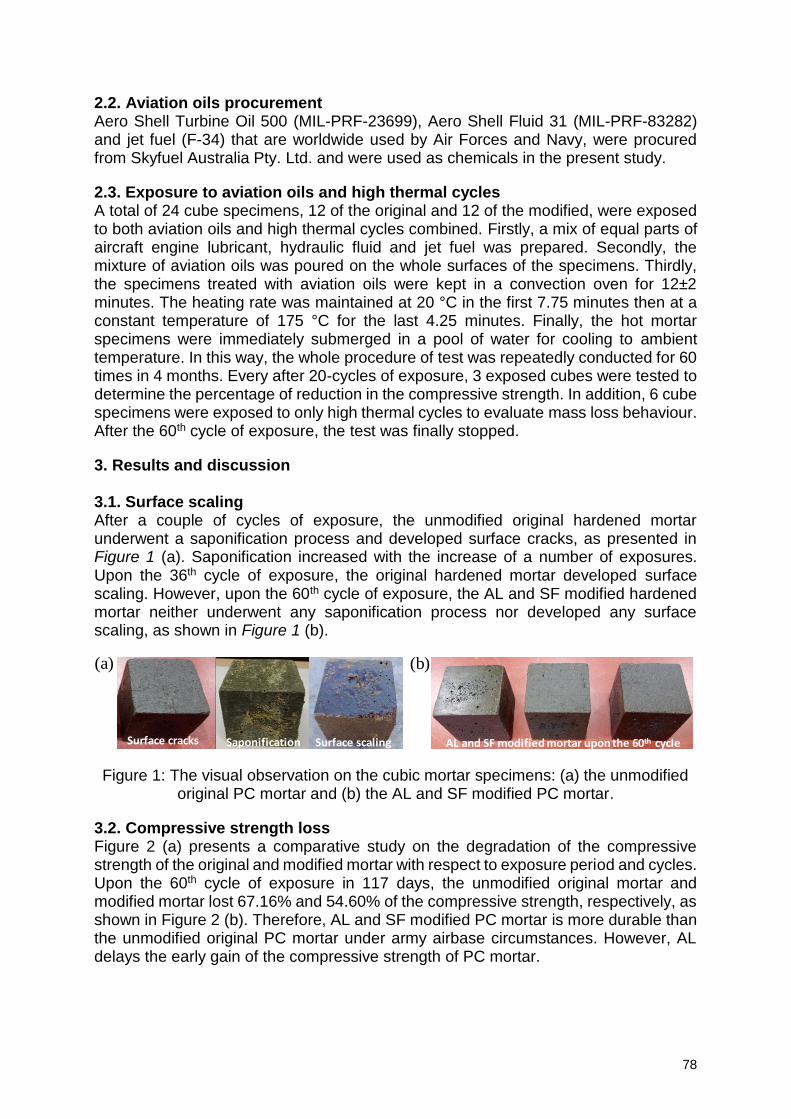
78
2.2. Aviation oils procurement Aero Shell Turbine Oil 500 (MIL-PRF-23699), Aero Shell Fluid 31 (MIL-PRF-83282) and jet fuel (F-34) that are worldwide used by Air Forces and Navy, were procured from Skyfuel Australia Pty. Ltd. and were used as chemicals in the present study.
2.3. Exposure to aviation oils and high thermal cycles A total of 24 cube specimens, 12 of the original and 12 of the modified, were exposed to both aviation oils and high thermal cycles combined. Firstly, a mix of equal parts of aircraft engine lubricant, hydraulic fluid and jet fuel was prepared. Secondly, the mixture of aviation oils was poured on the whole surfaces of the specimens. Thirdly, the specimens treated with aviation oils were kept in a convection oven for 12±2 minutes. The heating rate was maintained at 20 °C in the first 7.75 minutes then at a constant temperature of 175 °C for the last 4.25 minutes. Finally, the hot mortar specimens were immediately submerged in a pool of water for cooling to ambient temperature. In this way, the whole procedure of test was repeatedly conducted for 60 times in 4 months. Every after 20-cycles of exposure, 3 exposed cubes were tested to determine the percentage of reduction in the compressive strength. In addition, 6 cube specimens were exposed to only high thermal cycles to evaluate mass loss behaviour. After the 60th cycle of exposure, the test was finally stopped.
3. Results and discussion 3.1. Surface scaling After a couple of cycles of exposure, the unmodified original hardened mortar underwent a saponification process and developed surface cracks, as presented in Figure 1 (a). Saponification increased with the increase of a number of exposures. Upon the 36th cycle of exposure, the original hardened mortar developed surface scaling. However, upon the 60th cycle of exposure, the AL and SF modified hardened mortar neither underwent any saponification process nor developed any surface scaling, as shown in Figure 1 (b).
Figure 1: The visual observation on the cubic mortar specimens: (a) the unmodified original PC mortar and (b) the AL and SF modified PC mortar.
3.2. Compressive strength loss Figure 2 (a) presents a comparative study on the degradation of the compressive strength of the original and modified mortar with respect to exposure period and cycles. Upon the 60th cycle of exposure in 117 days, the unmodified original mortar and modified mortar lost 67.16% and 54.60% of the compressive strength, respectively, as shown in Figure 2 (b). Therefore, AL and SF modified PC mortar is more durable than the unmodified original PC mortar under army airbase circumstances. However, AL delays the early gain of the compressive strength of PC mortar.
Surface cracks Saponification Surface scaling AL and SF modified mortar upon the 60th cycle
(a) (b)
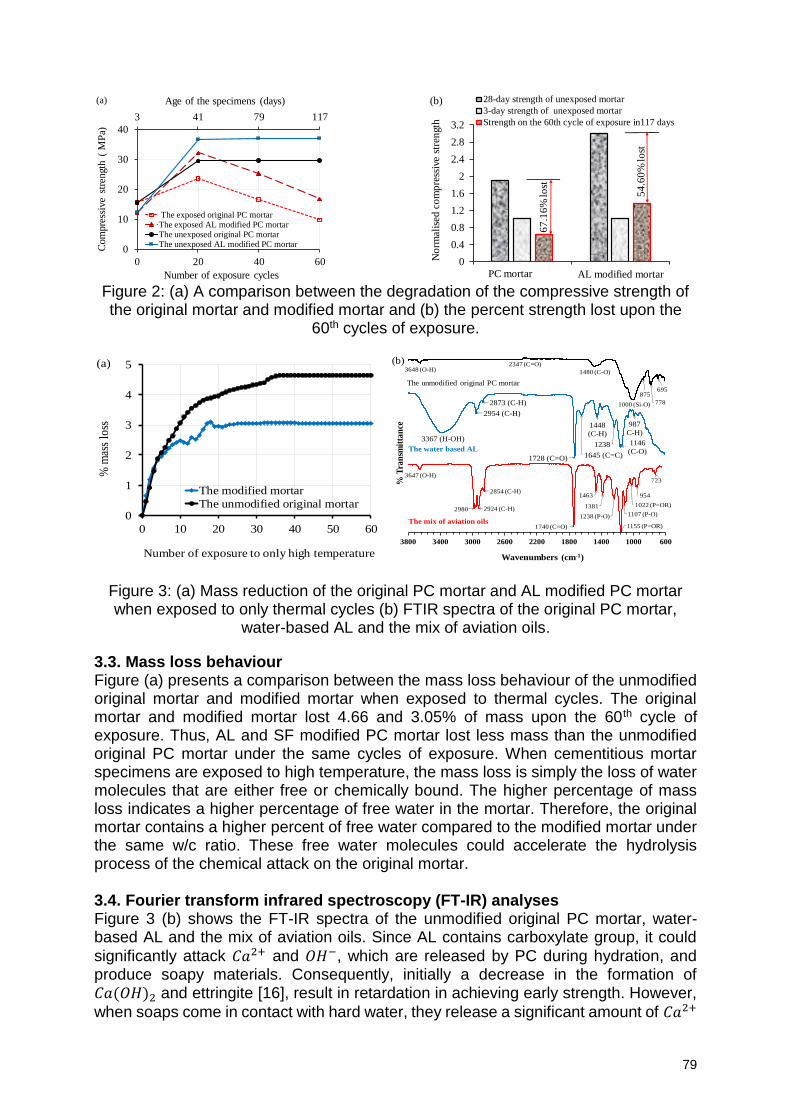
79
Figure 2: (a) A comparison between the degradation of the compressive strength of the original mortar and modified mortar and (b) the percent strength lost upon the
60th cycles of exposure.
Figure 3: (a) Mass reduction of the original PC mortar and AL modified PC mortar when exposed to only thermal cycles (b) FTIR spectra of the original PC mortar,
water-based AL and the mix of aviation oils.
3.3. Mass loss behaviour Figure (a) presents a comparison between the mass loss behaviour of the unmodified original mortar and modified mortar when exposed to thermal cycles. The original mortar and modified mortar lost 4.66 and 3.05% of mass upon the 60th cycle of exposure. Thus, AL and SF modified PC mortar lost less mass than the unmodified original PC mortar under the same cycles of exposure. When cementitious mortar specimens are exposed to high temperature, the mass loss is simply the loss of water molecules that are either free or chemically bound. The higher percentage of mass loss indicates a higher percentage of free water in the mortar. Therefore, the original mortar contains a higher percent of free water compared to the modified mortar under the same w/c ratio. These free water molecules could accelerate the hydrolysis process of the chemical attack on the original mortar. 3.4. Fourier transform infrared spectroscopy (FT-IR) analyses Figure 3 (b) shows the FT-IR spectra of the unmodified original PC mortar, water-based AL and the mix of aviation oils. Since AL contains carboxylate group, it could
significantly attack 𝐶𝑎2+ and 𝑂𝐻−, which are released by PC during hydration, and produce soapy materials. Consequently, initially a decrease in the formation of 𝐶𝑎(𝑂𝐻)2 and ettringite [16], result in retardation in achieving early strength. However,
when soaps come in contact with hard water, they release a significant amount of 𝐶𝑎2+
3 41 79 117
0
10
20
30
40
0 20 40 60
Age of the specimens (days)C
om
pre
ssiv
e st
rengt
h (
MP
a)
Number of exposure cycles
(a)
The exposed original PC mortarThe exposed AL modified PC mortarThe unexposed original PC mortarThe unexposed AL modified PC mortar
0
0.4
0.8
1.2
1.6
2
2.4
2.8
3.2
1 2
No
rmal
ised
co
mp
ress
ive
stre
ngt
h
(b) 28-day strength of unexposed mortar
3-day strength of unexposed mortar
Strength on the 60th cycle of exposure in117 days
PC mortar AL modified mortar
54
.60
% lo
st
67
.16
% lo
st
0
1
2
3
4
5
0 10 20 30 40 50 60
% m
ass
loss
Number of exposure to only high temperature
(a)
The modified mortar
The unmodified original mortar
695
778
875
1000 (Si-O)
1480 (C-O)
2347 (C=O)3648 (O-H)
987
C-H)
1146
(C-O)1238
1448
(C-H)
1645 (C=C)1728 (C=O)
2873 (C-H)
2954 (C-H)
3367 (H-OH)
723
954
1022 (P=OR)
1107 (P-O)
1155 (P=OR)
1238 (P-O)
1381
1463
1740 (C=O)
2854 (C-H)
2924 (C-H)2980
3647 (O-H)
60010001400180022002600300034003800
% T
ran
smit
tan
ce
Wavenumbers (cm-1)
The unmodified original PC mortar
The water based AL
The mix of aviation oils
(b)
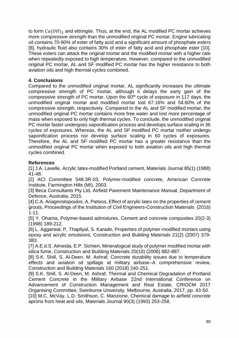
80
to form 𝐶𝑎(𝑂𝐻)2 and ettringite. Thus, at the end, the AL modified PC mortar achieves more compressive strength than the unmodified original PC mortar. Engine lubricating oil contains 70-90% of ester of fatty acid and a significant amount of phosphate esters [8], hydraulic fluid also contains 30% of ester of fatty acid and phosphate ester [10]. These esters can attack the original mortar and the modified mortar with a higher rate when repeatedly exposed to high temperature. However, compared to the unmodified original PC mortar, AL and SF modified PC mortar has the higher resistance to both aviation oils and high thermal cycles combined.
4. Conclusions Compared to the unmodified original mortar, AL significantly increases the ultimate compressive strength of PC mortar, although it delays the early gain of the compressive strength of PC mortar. Upon the 60th cycle of exposure in 117 days, the unmodified original mortar and modified mortar lost 67.16% and 54.60% of the compressive strength, respectively. Compared to the AL and SF modified mortar, the unmodified original PC mortar contains more free water and lost more percentage of mass when exposed to only high thermal cycles. To conclude, the unmodified original PC mortar faster undergoes saponification process and develops surface scaling in 36 cycles of exposures. Whereas, the AL and SF modified PC mortar neither undergo saponification process nor develop surface scaling in 60 cycles of exposures. Therefore, the AL and SF modified PC mortar has a greater resistance than the unmodified original PC mortar when exposed to both aviation oils and high thermal cycles combined.
References [1] J.A. Lavelle, Acrylic latex-modified Portland cement, Materials Journal 85(1) (1988) 41-48. [2] ACI Committee 548.3R-03, Polymer-modified concrete, American Concrete Institute, Farmington Hills (MI), 2003. [3] Beca Consultants Pty Ltd, Airfield Pavement Maintenance Manual, Department of Defence, Australia, 2015. [4] C.A. Anagnostopoulos, A. Patsios, Effect of acrylic latex on the properties of cement grouts, Proceedings of the Institution of Civil Engineers-Construction Materials (2016) 1-11. [5] Y. Ohama, Polymer-based admixtures, Cement and concrete composites 20(2-3) (1998) 189-212. [6] L. Aggarwal, P. Thapliyal, S. Karade, Properties of polymer-modified mortars using epoxy and acrylic emulsions, Construction and Building Materials 21(2) (2007) 379-383. [7] A.E.d.S. Almeida, E.P. Sichieri, Mineralogical study of polymer modified mortar with silica fume, Construction and Building Materials 20(10) (2006) 882-887. [8] S.K. Shill, S. Al-Deen, M. Ashraf, Concrete durability issues due to temperature effects and aviation oil spillage at military airbase–A comprehensive review, Construction and Building Materials 160 (2018) 240-251. [9] S.K. Shill, S. Al-Deen, M. Ashraf, Thermal and Chemical Degradation of Portland Cement Concrete in the Military Airbase 22nd International Conference on Advancement of Construction Management and Real Estate, CRIOCM 2017 Organising Committee, Swinburne University, Melbourne, Australia, 2017, pp. 43-50. [10] M.C. McVay, L.D. Smithson, C. Manzione, Chemical damage to airfield concrete aprons from heat and oils, Materials Journal 90(3) (1993) 253-258.
81
[11] M. McVay, J. Rish III, C. Sakezles, S. Mohseen, C. Beatty, Cements resistant to synthetic oil, hydraulic fluid, and elevated temperature environments, Materials Journal 92(2) (1995) 155-163. [12] M.C. Hironaka, L.J. Malvar, Jet exhaust damaged concrete, Concrete international 20(10) (1998) 32-35. [13] C. Lee, The Behaviour of Airfield Rigid Pavements Under the Influence of Jet Fuel, Lubricating and Hydraulic Fluids and Cyclic Heat Loading by F/A-18 APU Exhaust, The UNSW Canberra at ADFA Journal of Undergraduate Engineering Research 9(1) (2018). [14] Y. Ohama, Principle of latex modification and some typical properties of latex-modified mortars and concretes adhesion; binders (materials); bond (paste to aggregate); carbonation; chlorides; curing; diffusion, Materials Journal 84(6) (1987) 511-518. [15] S. Popovics, Strength losses of polymer-modified concretes under wet conditions, Special Publication 99 (1987) 165-190. [16] J. Larbi, J. Bijen, Interaction of polymers with Portland cement during hydration: a study of the chemistry of the pore solution of polymer-modified cement systems, Cement and concrete research 20(1) (1990) 139-147.
82
Evaluation of freeze thaw performance of GGBS concrete
T.A. Yikici1, E. Kesler2, Y. Akkaya2
1 Department of Civil Engineering, MEF University, Maslak Ayazaga Cad., 34396, Sariyer, Istanbul, Turkey – [email protected] 2 Department of Civil Engineering, Infrastructure Materials Laboratory, Istanbul Technical University, Maslak, 34467, Sariyer Istanbul, Turkey – [email protected]; [email protected]
Abstract Ground granulated blast furnace slag (GGBS) is an eco-friendly supplementary cementitious material which is being widely used in the concrete production. Use of GGBS improves fresh and mechanical properties of concrete as well as permeability and durability. In this study effectiveness of air entraining admixtures on the behavior of GGBS concrete mixtures was investigated in case of freeze-thaw resistant structural elements. Effects of maximum size of aggregate and paste content on air void structure were investigated. In order to evaluate freeze-thaw durability, freeze-thaw resistance tests were performed according to TSE CEN/TS 12390. Moreover, air void system within the hardened concrete was analyzed by means of ASTM C 457. Hardened concrete air void parameters such as air void content, spacing factor and specific surface area, obtained from the analysis, are the main parameters that affect the freeze-thaw resistance. Correlations between fresh concrete properties and entrained air void structure were analyzed. Laboratory studies were conducted using concrete delivered from the batching plant. Keywords: GGBS concrete, freeze-thaw, frost salt resistance, air void analysis 1. Introduction Ground granulated blast furnace slag (GGBS) is widely used in the construction industry for producing sustainable and high-performance concrete. As a by-product of steel production process, GGBS has a similar chemical composition to Portland cement with large amounts of calcium, silicium and aluminum oxides and therefore is being used as supplementary cementitious material to produce ecofriendly concrete with enhanced characteristics such as low permeability, resistance to chloride penetration, sulfate attack, and alkali aggregate reactions [1][2][3]. However, some studies reveal that GGBS concrete presents lower resistance against frost salt scaling. Although it is known that concrete produced with stable entrained air void system shows good freeze-thaw performance, several studies reported that use of GGBS in concrete adversely affects air void structure [4][5]. Additionally, since GGBS concrete results in higher carbonation (because carbonation due to its low alkalinity) compared to Portland cement concrete, scaling due to frost salt attack increases [6] [7]. In this study, GGBS concrete mixtures were designed for extreme applications such as diaphragm wall construction and tunnel corbels, where concrete properties including long retention time, long distance pumpability and flowability is required. Additionally, selected concrete mixture expected to resist chlorides and freeze-thaw attack effectively. Freeze-thaw resistance of GGBS concrete with a slag content of 67% (CEM III/B 32.5N) was determined by means of TSE CEN/TS 12390. The main parameters for hardened concrete air void system were analyzed (ASTM C457) and results were
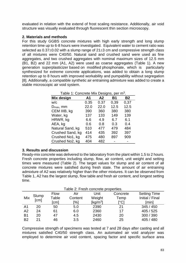
83
evaluated in relation with the extend of frost scaling resistance. Additionally, air void structure was visually evaluated through fluorescent thin section microscopy. 2. Materials and methods For this study GGBS concrete mixtures with high early strength and long slump retention time up to 6-8 hours were investigated. Equivalent water to cement ratio was
selected as 0.370.02 with a slump range of 213 cm and compressive strength class of all mixtures were C40/50. Natural sand and crushed sand were used as fine aggregates, and two crushed aggregates with nominal maximum sizes of 12.5 mm (B1, B2) and 22 mm (A1, A2) were used as coarse aggregates (Table 1). A new generation superplasticizer based on modified phosphonate, which is particularly synthesized for extreme concrete applications, was added to obtain a long slump retention up to 8 hours with improved workability and pumpability without segregation [8]. Additionally, a compatible synthetic air entraining admixture was added to create a stable microscopic air void system.
Table 1: Concrete Mix Designs, per m3.
Mix design A1 A2 B1 B2
w/c 0.35 0.37 0,39 0,37 Dmax, mm 22.0 22.0 12.5 12.5 CEM IIIB, kg 390 360 380 380 Water, kg 137 133 149 139 HRWR, kg 6.6 4.9 6.7 6.1 AEA, kg 0.6 0.8 0.3 0.4 Natural Sand, kg 510 477 479 484 Crushed Sand, kg 414 435 392 397 Crushed No1, kg 475 480 897 909 Crushed No2, kg 404 482 - -
3. Results and discussion Ready-mix concrete was delivered to the laboratory from the plant within 1.5 to 2 hours. Fresh concrete properties including slump, flow, air content, unit weight and setting times were measured (Table 2). The target values for slump and air content of all concrete mixtures were satisfied during fresh state. The amount of air entraining admixture of A2 was relatively higher than the other mixtures. It can be observed from Table 1, A2 has the largest slump, flow table and fresh air content, and longest setting time.
Table 2: Fresh concrete properties.
Mix Slump [cm]
Flow Table [cm]
Air Content
[%]
Unit Weight [kg/m3]
Concrete Temp [°C]
Setting Time Initial / Final
[min]
A1 20 50 5.0 2390 21 345 / 450 A2 24 61 6.0 2360 17 405 / 525 B1 20 47 4.5 2430 20 300 / 390 B2 21 46 3.5 2460 25 405 / 480
Compressive strength of specimens was tested at 7 and 28 days after casting and all mixtures satisfied C40/50 strength class. An automated air void analyzer was employed to determine air void content, spacing factor and specific surface area
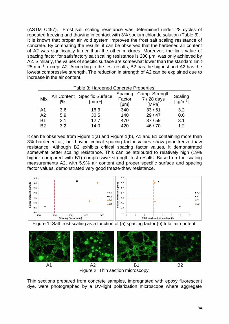
84
(ASTM C457). Frost salt scaling resistance was determined under 28 cycles of repeated freezing and thawing in contact with 3% sodium chloride solution (Table 3). It is known that proper air void system improves the frost salt scaling resistance of concrete. By comparing the results, it can be observed that the hardened air content of A2 was significantly larger than the other mixtures. Moreover, the limit value of spacing factor for satisfactory salt scaling resistance is 200 μm, was only achieved by A2. Similarly, the values of specific surface are somewhat lower than the standard limit 25 mm-1, except A2. According to the test results, B2 has the highest and A2 has the lowest compressive strength. The reduction in strength of A2 can be explained due to increase in the air content.
Table 3: Hardened Concrete Properties.
Mix Air Content
[%] Specific Surface
[mm-1]
Spacing Factor [μm]
Comp. Strength 7 / 28 days
[MPa]
Scaling [kg/m2]
A1 3.6 16.3 340 33 / 51 3.2 A2 5.9 30.5 140 29 / 47 0.6 B1 3.1 12.7 470 37 / 59 3.1 B2 3.2 14.0 420 46 / 70 1.2
It can be observed from Figure 1(a) and Figure 1(b), A1 and B1 containing more than 3% hardened air, but having critical spacing factor values show poor freeze-thaw resistance. Although B2 exhibits critical spacing factor values, it demonstrated somewhat better scaling resistance. This can be attributed to relatively high (19% higher compared with B1) compressive strength test results. Based on the scaling measurements A2, with 5.9% air content and proper specific surface and spacing factor values, demonstrated very good freeze-thaw resistance.
Figure 1: Salt frost scaling as a function of (a) spacing factor (b) total air content.
A1 A2 B1 B2
Figure 2: Thin section microscopy. Thin sections prepared from concrete samples, impregnated with epoxy fluorescent dye, were photographed by a UV-light polarization microscope where aggregate
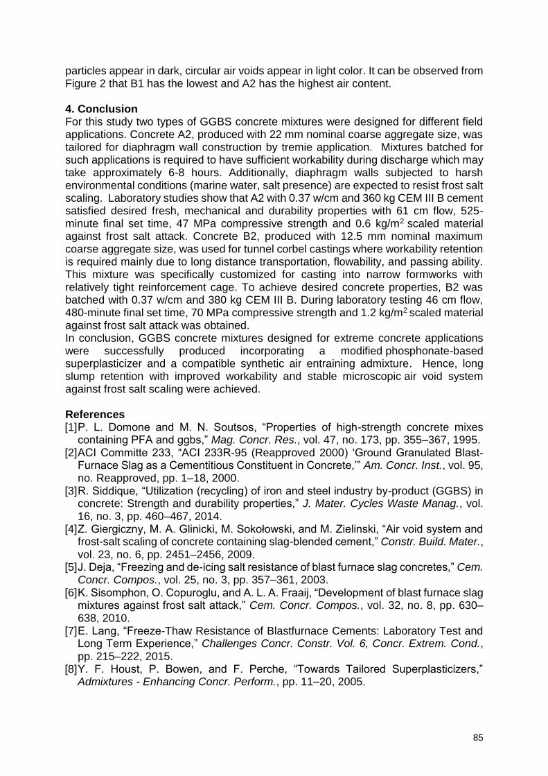
85
particles appear in dark, circular air voids appear in light color. It can be observed from Figure 2 that B1 has the lowest and A2 has the highest air content. 4. Conclusion For this study two types of GGBS concrete mixtures were designed for different field applications. Concrete A2, produced with 22 mm nominal coarse aggregate size, was tailored for diaphragm wall construction by tremie application. Mixtures batched for such applications is required to have sufficient workability during discharge which may take approximately 6-8 hours. Additionally, diaphragm walls subjected to harsh environmental conditions (marine water, salt presence) are expected to resist frost salt scaling. Laboratory studies show that A2 with 0.37 w/cm and 360 kg CEM III B cement satisfied desired fresh, mechanical and durability properties with 61 cm flow, 525-minute final set time, 47 MPa compressive strength and 0.6 kg/m2 scaled material against frost salt attack. Concrete B2, produced with 12.5 mm nominal maximum coarse aggregate size, was used for tunnel corbel castings where workability retention is required mainly due to long distance transportation, flowability, and passing ability. This mixture was specifically customized for casting into narrow formworks with relatively tight reinforcement cage. To achieve desired concrete properties, B2 was batched with 0.37 w/cm and 380 kg CEM III B. During laboratory testing 46 cm flow, 480-minute final set time, 70 MPa compressive strength and 1.2 kg/m2 scaled material against frost salt attack was obtained. In conclusion, GGBS concrete mixtures designed for extreme concrete applications were successfully produced incorporating a modified phosphonate-based superplasticizer and a compatible synthetic air entraining admixture. Hence, long slump retention with improved workability and stable microscopic air void system against frost salt scaling were achieved. References [1] P. L. Domone and M. N. Soutsos, “Properties of high-strength concrete mixes
containing PFA and ggbs,” Mag. Concr. Res., vol. 47, no. 173, pp. 355–367, 1995. [2] ACI Committe 233, “ACI 233R-95 (Reapproved 2000) ‘Ground Granulated Blast-
Furnace Slag as a Cementitious Constituent in Concrete,’” Am. Concr. Inst., vol. 95, no. Reapproved, pp. 1–18, 2000.
[3] R. Siddique, “Utilization (recycling) of iron and steel industry by-product (GGBS) in concrete: Strength and durability properties,” J. Mater. Cycles Waste Manag., vol. 16, no. 3, pp. 460–467, 2014.
[4] Z. Giergiczny, M. A. Glinicki, M. Sokołowski, and M. Zielinski, “Air void system and frost-salt scaling of concrete containing slag-blended cement,” Constr. Build. Mater., vol. 23, no. 6, pp. 2451–2456, 2009.
[5] J. Deja, “Freezing and de-icing salt resistance of blast furnace slag concretes,” Cem. Concr. Compos., vol. 25, no. 3, pp. 357–361, 2003.
[6] K. Sisomphon, O. Copuroglu, and A. L. A. Fraaij, “Development of blast furnace slag mixtures against frost salt attack,” Cem. Concr. Compos., vol. 32, no. 8, pp. 630–638, 2010.
[7] E. Lang, “Freeze-Thaw Resistance of Blastfurnace Cements: Laboratory Test and Long Term Experience,” Challenges Concr. Constr. Vol. 6, Concr. Extrem. Cond., pp. 215–222, 2015.
[8] Y. F. Houst, P. Bowen, and F. Perche, “Towards Tailored Superplasticizers,” Admixtures - Enhancing Concr. Perform., pp. 11–20, 2005.
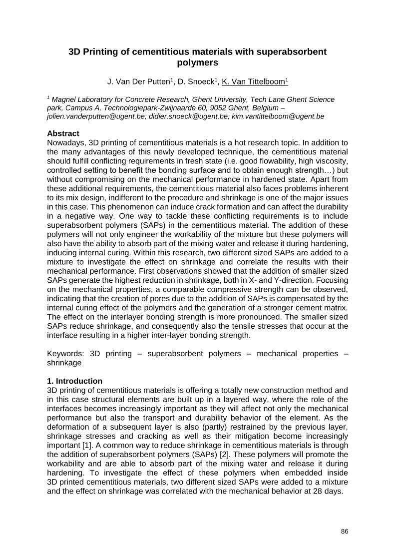
86
3D Printing of cementitious materials with superabsorbent polymers
J. Van Der Putten1, D. Snoeck1, K. Van Tittelboom1
1 Magnel Laboratory for Concrete Research, Ghent University, Tech Lane Ghent Science park, Campus A, Technologiepark-Zwijnaarde 60, 9052 Ghent, Belgium – [email protected]; [email protected]; [email protected]
Abstract Nowadays, 3D printing of cementitious materials is a hot research topic. In addition to the many advantages of this newly developed technique, the cementitious material should fulfill conflicting requirements in fresh state (i.e. good flowability, high viscosity, controlled setting to benefit the bonding surface and to obtain enough strength…) but without compromising on the mechanical performance in hardened state. Apart from these additional requirements, the cementitious material also faces problems inherent to its mix design, indifferent to the procedure and shrinkage is one of the major issues in this case. This phenomenon can induce crack formation and can affect the durability in a negative way. One way to tackle these conflicting requirements is to include superabsorbent polymers (SAPs) in the cementitious material. The addition of these polymers will not only engineer the workability of the mixture but these polymers will also have the ability to absorb part of the mixing water and release it during hardening, inducing internal curing. Within this research, two different sized SAPs are added to a mixture to investigate the effect on shrinkage and correlate the results with their mechanical performance. First observations showed that the addition of smaller sized SAPs generate the highest reduction in shrinkage, both in X- and Y-direction. Focusing on the mechanical properties, a comparable compressive strength can be observed, indicating that the creation of pores due to the addition of SAPs is compensated by the internal curing effect of the polymers and the generation of a stronger cement matrix. The effect on the interlayer bonding strength is more pronounced. The smaller sized SAPs reduce shrinkage, and consequently also the tensile stresses that occur at the interface resulting in a higher inter-layer bonding strength. Keywords: 3D printing – superabsorbent polymers – mechanical properties – shrinkage 1. Introduction 3D printing of cementitious materials is offering a totally new construction method and in this case structural elements are built up in a layered way, where the role of the interfaces becomes increasingly important as they will affect not only the mechanical performance but also the transport and durability behavior of the element. As the deformation of a subsequent layer is also (partly) restrained by the previous layer, shrinkage stresses and cracking as well as their mitigation become increasingly important [1]. A common way to reduce shrinkage in cementitious materials is through the addition of superabsorbent polymers (SAPs) [2]. These polymers will promote the workability and are able to absorb part of the mixing water and release it during hardening. To investigate the effect of these polymers when embedded inside 3D printed cementitious materials, two different sized SAPs were added to a mixture and the effect on shrinkage was correlated with the mechanical behavior at 28 days.
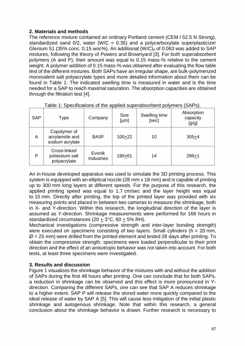
87
2. Materials and methods The reference mixture contained an ordinary Portland cement (CEM I 52.5 N Strong), standardized sand 0/2, water (W/C = 0.35) and a polycarboxylate superplasticizer Glenium 51 (35% conc. 0.15 woc%). An additional (W/C)a of 0.063 was added to SAP mixtures, following the theory of Powers and Brownyard [3]. For both superabsorbent polymers (A and P), their amount was equal to 0.15 mass-% relative to the cement weight. A polymer addition of 0.15 mass-% was obtained after evaluating the flow table test of the different mixtures. Both SAPs have an irregular shape, are bulk-polymerized monovalent salt polyacrylate types and more detailed information about them can be found in Table 1. The indicated swelling time is measured in water and is the time needed for a SAP to reach maximal saturation. The absorption capacities are obtained through the filtration test [4].
Table 1: Specifications of the applied superabsorbent polymers (SAPs).
SAP Type Company Size [µm]
Swelling time [sec]
Absorption capacity
[g/g]
A Copolymer of
acrylamide and sodium acrylate
BASF 100+22 10 305+4
P Cross-linked
potassium salt polyacrylate
Evonik Industries
190+61 14 286+1
An in-house developed apparatus was used to simulate the 3D printing process. This system is equipped with an elliptical nozzle (28 mm x 18 mm) and is capable of printing up to 300 mm long layers at different speeds. For the purpose of this research, the applied printing speed was equal to 1.7 cm/sec and the layer height was equal to 15 mm. Directly after printing, the top of the printed layer was provided with six measuring points and placed in between two cameras to measure the shrinkage, both in X- and Y-direction. Within this research, the longitudinal direction of the layer is assumed as Y-direction. Shrinkage measurements were performed for 168 hours in standardized circumstances (20 + 3°C, 60 + 5% RH). Mechanical investigations (compressive strength and inter-layer bonding strength) were executed on specimens consisting of two layers. Small cylinders (h = 20 mm, Ø = 25 mm) were drilled from the printed element and tested 28 days after printing. To obtain the compressive strength, specimens were loaded perpendicular to their print direction and the effect of an anisotropic behavior was not taken into account. For both tests, at least three specimens were investigated. 3. Results and discussion Figure 1 visualizes the shrinkage behavior of the mixtures with and without the addition of SAPs during the first 48 hours after printing. One can conclude that for both SAPs, a reduction in shrinkage can be observed and this effect is more pronounced in Y-direction. Comparing the different SAPs, one can see that SAP A reduces shrinkage to a higher extent. SAP P will release the stored water more quickly compared to the ideal release of water by SAP A [5]. This will cause less mitigation of the initial plastic shrinkage and autogenous shrinkage. Note that within this research, a general conclusion about the shrinkage behavior is drawn. Further research is necessary to
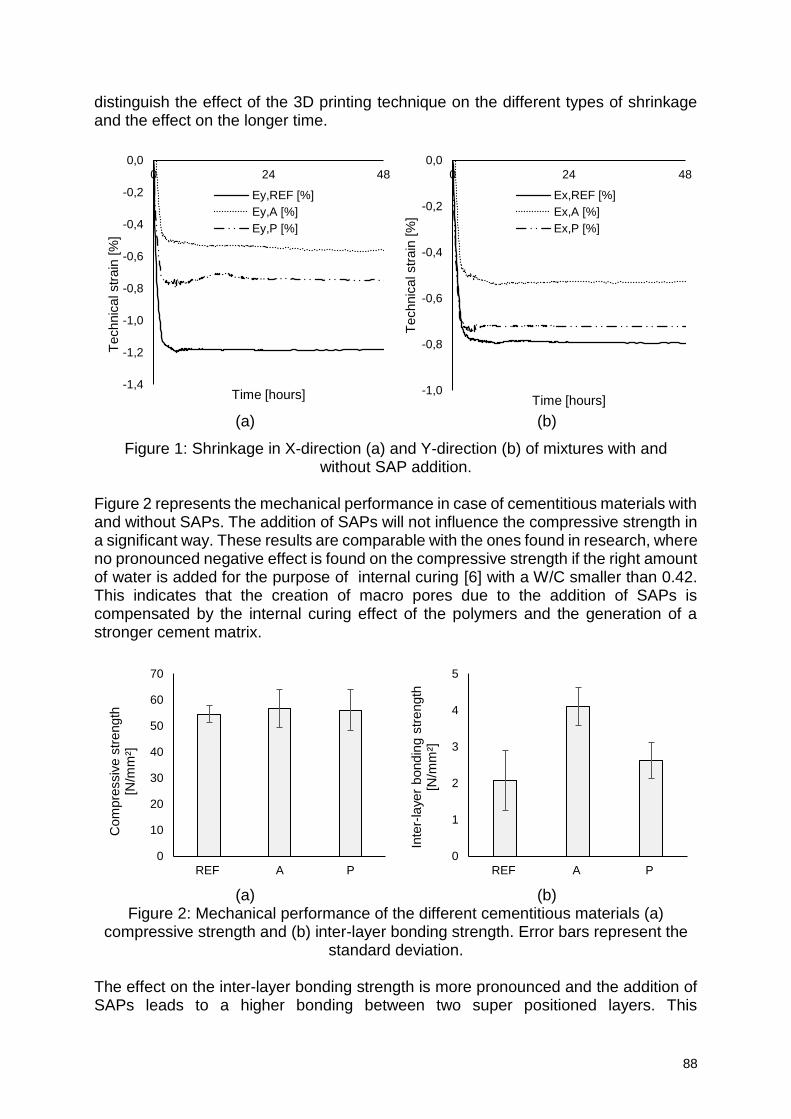
88
distinguish the effect of the 3D printing technique on the different types of shrinkage and the effect on the longer time.
(a) (b)
Figure 1: Shrinkage in X-direction (a) and Y-direction (b) of mixtures with and without SAP addition.
Figure 2 represents the mechanical performance in case of cementitious materials with and without SAPs. The addition of SAPs will not influence the compressive strength in a significant way. These results are comparable with the ones found in research, where no pronounced negative effect is found on the compressive strength if the right amount of water is added for the purpose of internal curing [6] with a W/C smaller than 0.42. This indicates that the creation of macro pores due to the addition of SAPs is compensated by the internal curing effect of the polymers and the generation of a stronger cement matrix.
(a) (b)
Figure 2: Mechanical performance of the different cementitious materials (a) compressive strength and (b) inter-layer bonding strength. Error bars represent the
standard deviation. The effect on the inter-layer bonding strength is more pronounced and the addition of SAPs leads to a higher bonding between two super positioned layers. This
-1,4
-1,2
-1,0
-0,8
-0,6
-0,4
-0,2
0,0
0 24 48
Technic
al str
ain
[%
]
Time [hours]
Ey,REF [%]
Ey,A [%]
Ey,P [%]
-1,0
-0,8
-0,6
-0,4
-0,2
0,0
0 24 48
Technic
al str
ain
[%
]Time [hours]
Ex,REF [%]
Ex,A [%]
Ex,P [%]
0
10
20
30
40
50
60
70
REF A P
Com
pre
ssiv
e s
trength
[N
/mm
²]
0
1
2
3
4
5
REF A P
Inte
r-la
yer
bondin
g s
trength
[N
/mm
²]
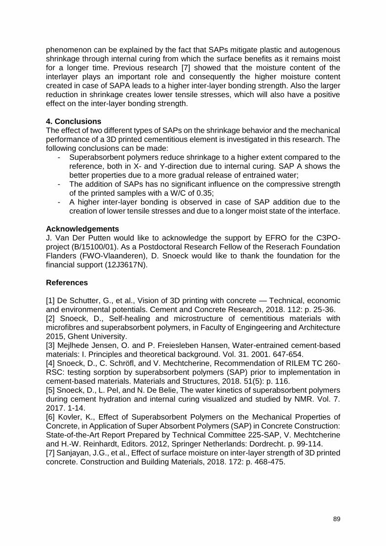
89
phenomenon can be explained by the fact that SAPs mitigate plastic and autogenous shrinkage through internal curing from which the surface benefits as it remains moist for a longer time. Previous research [7] showed that the moisture content of the interlayer plays an important role and consequently the higher moisture content created in case of SAPA leads to a higher inter-layer bonding strength. Also the larger reduction in shrinkage creates lower tensile stresses, which will also have a positive effect on the inter-layer bonding strength. 4. Conclusions The effect of two different types of SAPs on the shrinkage behavior and the mechanical performance of a 3D printed cementitious element is investigated in this research. The following conclusions can be made:
- Superabsorbent polymers reduce shrinkage to a higher extent compared to the reference, both in X- and Y-direction due to internal curing. SAP A shows the better properties due to a more gradual release of entrained water;
- The addition of SAPs has no significant influence on the compressive strength of the printed samples with a W/C of 0.35;
- A higher inter-layer bonding is observed in case of SAP addition due to the creation of lower tensile stresses and due to a longer moist state of the interface.
Acknowledgements J. Van Der Putten would like to acknowledge the support by EFRO for the C3PO-project (B/15100/01). As a Postdoctoral Research Fellow of the Reserach Foundation Flanders (FWO-Vlaanderen), D. Snoeck would like to thank the foundation for the financial support (12J3617N). References [1] De Schutter, G., et al., Vision of 3D printing with concrete — Technical, economic and environmental potentials. Cement and Concrete Research, 2018. 112: p. 25-36. [2] Snoeck, D., Self-healing and microstructure of cementitious materials with microfibres and superabsorbent polymers, in Faculty of Engingeering and Architecture 2015, Ghent University. [3] Mejlhede Jensen, O. and P. Freiesleben Hansen, Water-entrained cement-based materials: I. Principles and theoretical background. Vol. 31. 2001. 647-654. [4] Snoeck, D., C. Schröfl, and V. Mechtcherine, Recommendation of RILEM TC 260-RSC: testing sorption by superabsorbent polymers (SAP) prior to implementation in cement-based materials. Materials and Structures, 2018. 51(5): p. 116. [5] Snoeck, D., L. Pel, and N. De Belie, The water kinetics of superabsorbent polymers during cement hydration and internal curing visualized and studied by NMR. Vol. 7. 2017. 1-14. [6] Kovler, K., Effect of Superabsorbent Polymers on the Mechanical Properties of Concrete, in Application of Super Absorbent Polymers (SAP) in Concrete Construction: State-of-the-Art Report Prepared by Technical Committee 225-SAP, V. Mechtcherine and H.-W. Reinhardt, Editors. 2012, Springer Netherlands: Dordrecht. p. 99-114. [7] Sanjayan, J.G., et al., Effect of surface moisture on inter-layer strength of 3D printed concrete. Construction and Building Materials, 2018. 172: p. 468-475.
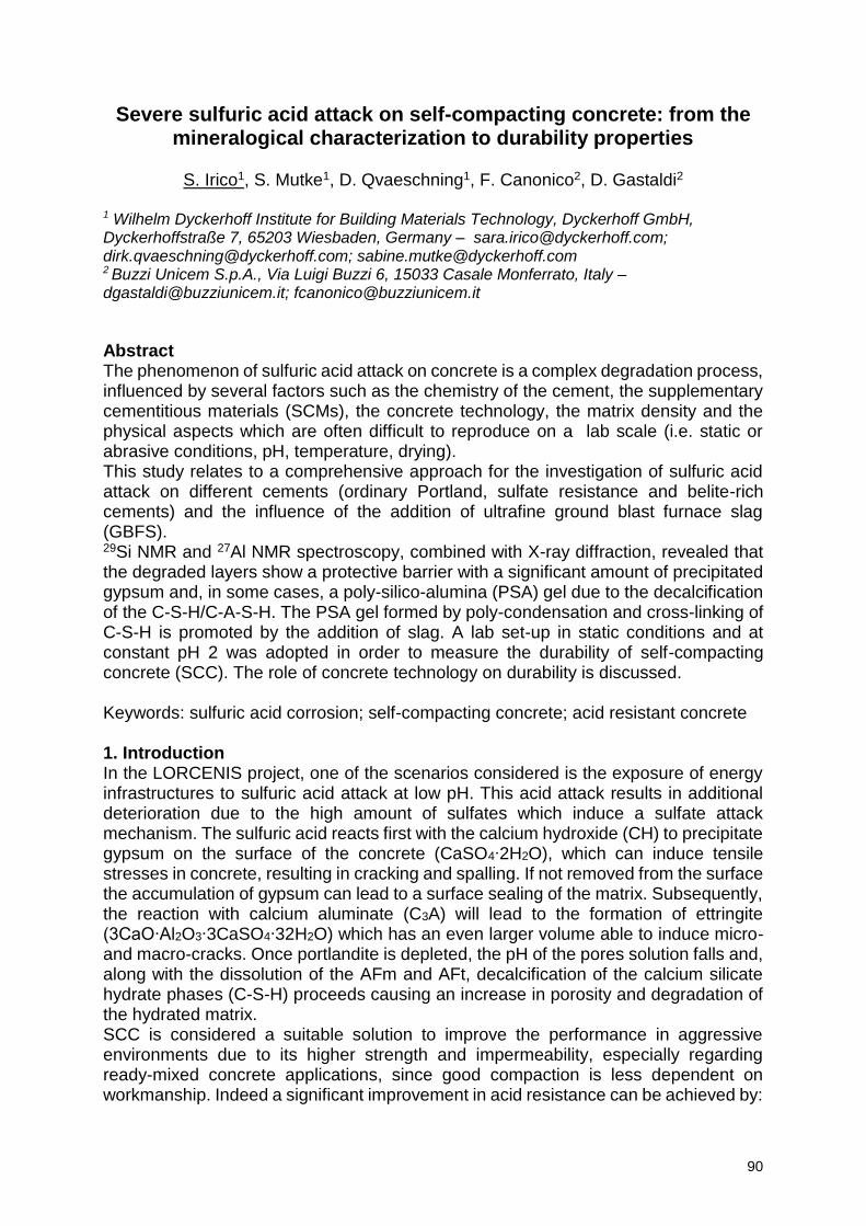
90
Severe sulfuric acid attack on self-compacting concrete: from the mineralogical characterization to durability properties
S. Irico1, S. Mutke1, D. Qvaeschning1, F. Canonico2, D. Gastaldi2
1 Wilhelm Dyckerhoff Institute for Building Materials Technology, Dyckerhoff GmbH, Dyckerhoffstraße 7, 65203 Wiesbaden, Germany – [email protected]; [email protected]; [email protected] 2 Buzzi Unicem S.p.A., Via Luigi Buzzi 6, 15033 Casale Monferrato, Italy – [email protected]; [email protected]
Abstract The phenomenon of sulfuric acid attack on concrete is a complex degradation process, influenced by several factors such as the chemistry of the cement, the supplementary cementitious materials (SCMs), the concrete technology, the matrix density and the physical aspects which are often difficult to reproduce on a lab scale (i.e. static or abrasive conditions, pH, temperature, drying). This study relates to a comprehensive approach for the investigation of sulfuric acid attack on different cements (ordinary Portland, sulfate resistance and belite-rich cements) and the influence of the addition of ultrafine ground blast furnace slag (GBFS). 29Si NMR and 27Al NMR spectroscopy, combined with X-ray diffraction, revealed that the degraded layers show a protective barrier with a significant amount of precipitated gypsum and, in some cases, a poly-silico-alumina (PSA) gel due to the decalcification of the C-S-H/C-A-S-H. The PSA gel formed by poly-condensation and cross-linking of C-S-H is promoted by the addition of slag. A lab set-up in static conditions and at constant pH 2 was adopted in order to measure the durability of self-compacting concrete (SCC). The role of concrete technology on durability is discussed. Keywords: sulfuric acid corrosion; self-compacting concrete; acid resistant concrete 1. Introduction In the LORCENIS project, one of the scenarios considered is the exposure of energy infrastructures to sulfuric acid attack at low pH. This acid attack results in additional deterioration due to the high amount of sulfates which induce a sulfate attack mechanism. The sulfuric acid reacts first with the calcium hydroxide (CH) to precipitate gypsum on the surface of the concrete (CaSO4∙2H2O), which can induce tensile stresses in concrete, resulting in cracking and spalling. If not removed from the surface the accumulation of gypsum can lead to a surface sealing of the matrix. Subsequently, the reaction with calcium aluminate (C3A) will lead to the formation of ettringite (3CaO∙Al2O3∙3CaSO4∙32H2O) which has an even larger volume able to induce micro- and macro-cracks. Once portlandite is depleted, the pH of the pores solution falls and, along with the dissolution of the AFm and AFt, decalcification of the calcium silicate hydrate phases (C-S-H) proceeds causing an increase in porosity and degradation of the hydrated matrix. SCC is considered a suitable solution to improve the performance in aggressive environments due to its higher strength and impermeability, especially regarding ready-mixed concrete applications, since good compaction is less dependent on workmanship. Indeed a significant improvement in acid resistance can be achieved by:
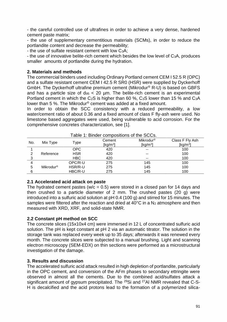
91
- the careful controlled use of ultrafines in order to achieve a very dense, hardened cement paste matrix; - the use of supplementary cementitious materials (SCMs), in order to reduce the portlandite content and decrease the permeability; - the use of sulfate resistant cement with low C3A; - the use of innovative belite-rich cement which besides the low level of C3A, produces smaller amounts of portlandite during the hydration. 2. Materials and methods The commercial binders used including Ordinary Portland cement CEM I 52.5 R (OPC) and a sulfate resistant cement CEM I 42.5 R SR0 (HSR) were supplied by Dyckerhoff GmbH. The Dyckerhoff ultrafine premium cement (Mikrodur® R-U) is based on GBFS and has a particle size of d95 < 20 µm. The belite-rich cement is an experimental Portland cement in which the C2S is higher than 60 %, C3S lower than 15 % and C3A lower than 5 %. The Mikrodur® cement was added at a fixed amount. In order to obtain the SCC consistency with a reduced permeability, a low water/cement ratio of about 0.36 and a fixed amount of class F fly-ash were used. No limestone based aggregates were used, being vulnerable to acid corrosion. For the comprehensive concretes characterization, see [1].
Table 1: Binder compositions of the SCCs.
No. Mix Type Type Cement [kg/m3]
Mikrodur® [kg/m3]
Class F Fly Ash [kg/m3]
1 OPC 420 -- 100 2 Reference HSR 420 -- 100 3 HBC 420 -- 100
4 OPC/R-U 275 145 100 5 Mikrodur® HSR/R-U 275 145 100 6 HBC/R-U 275 145 100
2.1 Accelerated acid attack on paste The hydrated cement pastes (w/c = 0.5) were stored in a closed pan for 14 days and then crushed to a particle diameter of 2 mm. The crushed pastes (20 g) were introduced into a sulfuric acid solution at pH 0.4 (100 g) and stirred for 15 minutes. The samples were filtered after the reaction and dried at 40°C in a N2 atmosphere and then measured with XRD, XRF, and solid-state NMR. 2.2 Constant pH method on SCC The concrete slices (15x10x4 cm) were immersed in 12 L of concentrated sulfuric acid solution. The pH is kept constant at pH 2 via an automatic titrator. The solution in the storage tank was replaced every week up to 35 days; afterwards it was renewed every month. The concrete slices were subjected to a manual brushing. Light and scanning electron microscopy (SEM-EDX) on thin sections were performed as a microstructural investigation of the damage. 3. Results and discussion The accelerated sulfuric acid attack resulted in high depletion of portlandite, particularly in the OPC cement, and conversion of the AFm phases to secondary ettringite were observed in almost all the cements. Due to the combined acid/sulfates attack a significant amount of gypsum precipitated. The 29Si and 27Al NMR revealed that C-S-H is decalcified and the acid protons lead to the formation of a polymerized silica-
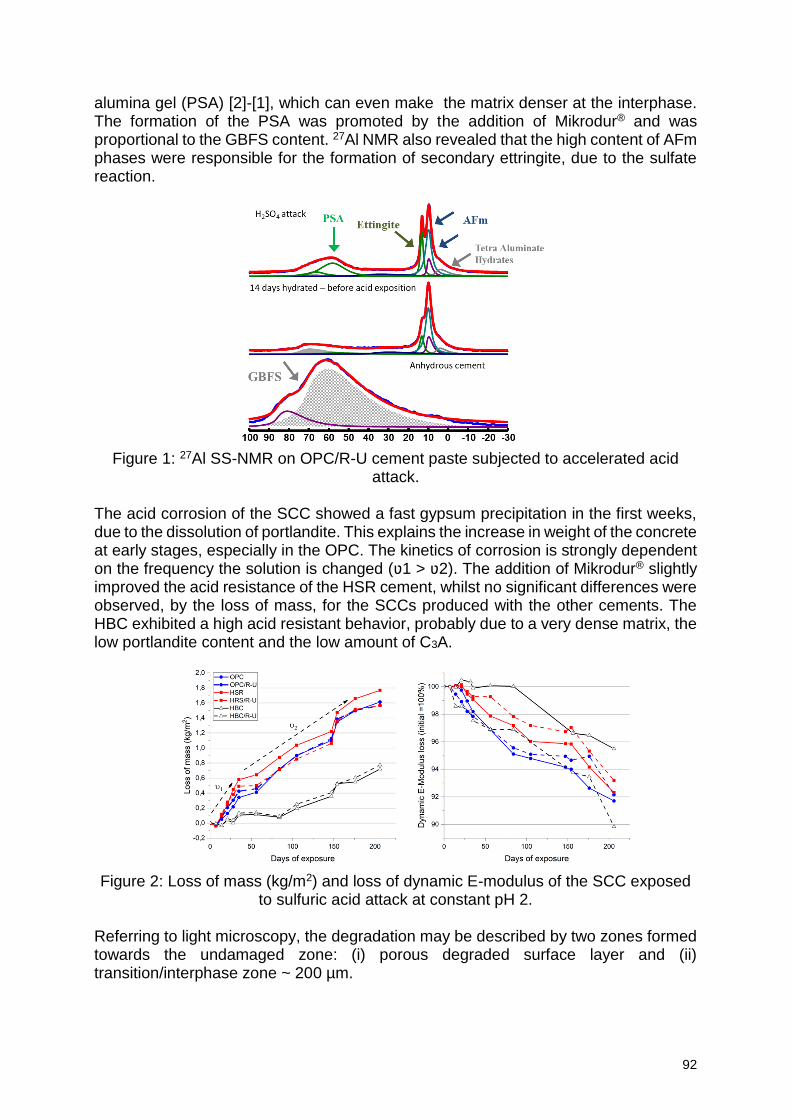
92
alumina gel (PSA) [2]-[1], which can even make the matrix denser at the interphase. The formation of the PSA was promoted by the addition of Mikrodur® and was proportional to the GBFS content. 27Al NMR also revealed that the high content of AFm phases were responsible for the formation of secondary ettringite, due to the sulfate reaction.
Figure 1: 27Al SS-NMR on OPC/R-U cement paste subjected to accelerated acid
attack.
The acid corrosion of the SCC showed a fast gypsum precipitation in the first weeks, due to the dissolution of portlandite. This explains the increase in weight of the concrete at early stages, especially in the OPC. The kinetics of corrosion is strongly dependent on the frequency the solution is changed (ʋ1 > ʋ2). The addition of Mikrodur® slightly improved the acid resistance of the HSR cement, whilst no significant differences were observed, by the loss of mass, for the SCCs produced with the other cements. The HBC exhibited a high acid resistant behavior, probably due to a very dense matrix, the low portlandite content and the low amount of C3A.
Figure 2: Loss of mass (kg/m2) and loss of dynamic E-modulus of the SCC exposed
to sulfuric acid attack at constant pH 2. Referring to light microscopy, the degradation may be described by two zones formed towards the undamaged zone: (i) porous degraded surface layer and (ii) transition/interphase zone ~ 200 µm.
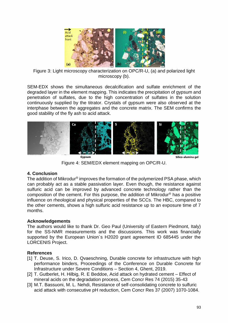
93
Figure 3: Light microscopy characterization on OPC/R-U, (a) and polarized light
microscopy (b).
SEM-EDX shows the simultaneous decalcification and sulfate enrichment of the degraded layer in the element mapping. This indicates the precipitation of gypsum and penetration of sulfates, due to the high concentration of sulfates in the solution continuously supplied by the titrator. Crystals of gypsum were also observed at the interphase between the aggregates and the concrete matrix. The SEM confirms the good stability of the fly ash to acid attack.
Figure 4: SEM/EDX element mapping on OPC/R-U.
4. Conclusion The addition of Mikrodur® improves the formation of the polymerized PSA phase, which can probably act as a stable passivation layer. Even though, the resistance against sulfuric acid can be improved by advanced concrete technology rather than the composition of the cement. For this purpose, the addition of Mikrodur® has a positive influence on rheological and physical properties of the SCCs. The HBC, compared to the other cements, shows a high sulfuric acid resistance up to an exposure time of 7 months.
Acknowledgements The authors would like to thank Dr. Geo Paul (University of Eastern Piedmont, Italy) for the SS-NMR measurements and the discussions. This work was financially supported by the European Union´s H2020 grant agreement ID 685445 under the LORCENIS Project. References [1] T. Deuse, S. Irico, D. Qvaeschning, Durable concrete for infrastructure with high
performance binders, Proceedings of the Conference on Durable Concrete for Infrastructure under Severe Conditions – Section 4, Ghent, 2019.
[2] T. Gutberlet, H. Hilbig, R. E Beddoe, Acid attack on hydrated cement – Effect of mineral acids on the degradation process, Cem Concr Res 74 (2015) 35-43
[3] M.T. Bassuoni, M. L. Nehdi, Resistance of self-consolidating concrete to sulfuric acid attack with consecutive pH reduction, Cem Concr Res 37 (2007) 1070-1084.
94
Behaviour of pre-cracked self-healing cementitious materials under repeated flexural loads
G. Anglani1, J.M. Tulliani2, P. Antonaci1
1 Department of Structural, Geotechnical and Building Engineering, Politecnico di Torino, Corso Duca degli Abruzzi 24, 10129 Torino, Italy – [email protected]; [email protected] 2 Department of Applied Science and Technology, Politecnico di Torino, Corso Duca degli Abruzzi 24, 10129 Torino, Italy – [email protected]
Abstract It is well-known that all cementitious materials tend to have defects, resulting from incorrect mix proportion or execution, shrinkage and other causes. Their low tensile strength, in combination with the presence of defects, makes them prone to cracking. Due to the possible concurrent or subsequent action of cyclic loading (as caused, for example, by traffic loads, micro-seismic phenomena, etc.), micro-cracks can propagate and coalesce into macro-cracks, ultimately leading to a reduction of durability or even collapse. In the last decade, growing attention has been paid to the study and development of preventive repair systems able to introduce some self-healing properties in the cementitious materials, with the aim to achieve higher safety standards while limiting the overall maintenance costs, both in term of repair work and suspension of the service. However, the behaviour of such self-healing composite materials subjected to cyclic loading has not been fully investigated yet. In this work, the cyclic flexural behaviour of cement mortar specimens containing macro-capsules filled with either organic or inorganic healing agents (a foaming polyurethane precursor or a sodium silicate solution, respectively) was experimentally investigated. Prisms were cast and cured in water for at least 28 days before testing. Then, the specimens were pre-cracked in three-point bending to release the healing agent from the embedded capsules upon cracking. After the hardening reaction of the healing agent inside the crack, the specimens were tested under cyclic flexural loading to evaluate the self-healing efficiency in terms of fatigue life extension, in comparison to reference mortar specimens without capsules. Promising results were achieved, suggesting that the proposed self-healing system can be effective in prolonging the material fatigue life. Keywords: self-healing, macrocapsules, mechanical fatigue
95
Self-healing phenomena evaluation in concretes with permeability reducing admixtures
J. Arndt1, D. Silva1, V. Cappellesso1, N. Petry1, A. Masuero1, D. Dal Molin1
1 Department of Civil Engineering, Self-healing of cementitious materials group, Núcleo Orientado para a Inovação da Construção (NORIE), Universidade Federal do Rio Grande do Sul, Osvaldo Aranha 99, 90035-190 Porto Alegre, Brazil – [email protected]; [email protected]; [email protected]; [email protected]; [email protected]; [email protected]
Abstract Reinforced concrete structures are normally exposed to a variety of severe environment conditions, in addition, concrete elements are highly susceptible to cracking. These cracks become entry areas for aggressive agents into the internal part of the structure, possibly causing a series of pathological manifestations and especially accelerating the corrosion process of the steel reinforcement, contributing to the reduction of the structure service life. In an attempt of reducing the deterioration caused by the cracks in concrete structures, the self-healing capacity of cementitious matrix has been highly studied. The phenomenon is defined as the capability of a material to recover and / or repair itself without requiring any external intervention. The researches related to the self-healing phenomenon in cementitious materials have increase exponentially, with great emphasis on new technologies that can be inserted in the cement matrix to contribute to the self-healing, as an example of these materials, the crystallizing admixtures can be one alternative. This work aims to evaluate the influence of different permeability reducing admixtures in the self-healing phenomenon in concrete mixes. Thus, an experimental matrix was developed using concrete mixes with water/cement ratio of 0.40 and two different reducing permeability admixtures. Self-healing phenomenon evaluation was done with cracks opened at 28 days and the specimens were exposed to wet/dry cycles, remaining two days under water and then drying for twelve days. As for the tests, the compressive strength test was performed on concrete cylinders, and the healing phenomenon was evaluated using two techniques: crack healing measurement using ultrasonic pulse and image analysis performed with an optical microscope. It is possible to observe the self-healing phenomenon by both methods, with significant results. The permeability reducing admixtures (PRA) were able to increase the healing process. Both PRAs used in this this study presented equivalent performance in the conducted tests. Keywords: self-healing, permeability reducing admixtures, concrete, wet/dry cycles 1. Introduction Permeability reducing admixtures (PRA) is one of the alternatives to enhance the autonomic self-healing processes, being able to promote the sealing and the water reduction permeability in cementitious matrixes. PRA have the capability to fill cracks up to 0.4mm when added to the cement matrix. Through the time, with the occurrence of cracks and sufficient water / moisture entry into these cracks, there is the formation of an insoluble crystalline structure with products like C-S-H, Ca(OH)2 or ettringite crystals, depending on the size of the pores and the concentration of the solution penetrating these pores [1]. Active components react with the Ca(OH)2 to form crystalline products that dissociate the small voids, seal capillaries pores, and fill cracks
96
in concrete. Thus, the purpose of this study is to evaluate the influence of two permeability reducing admixtures on the self-healing concretes properties, with water/cement ratio of 0.40, using ultrasonic pulse velocity and optical microscopy techniques. 2. Materials and methods 2.1 Materials The cement used is the Portland cement with limestone (CPII-F) – similar to Type IIA
(BS 8500-1: 2006). Its carbonate material is limited between 6-10%, specific gravity
3.11 g/cm³, specific area of 5.786 m²/g and fire loss of 5.2%. The fine aggregate used
is a quartz sand with 1.89 fineness modulus, maximum diameter of 2.36mm, specific
gravity of 2.54 g/cm³, unit gravity of 1.49 g/cm³ and absorption rate of 1.30%. The
coarse aggregate is basaltic rock with fineness modulus of 6.10, maximum diameter
of 12.5 mm, specific gravity of 3.01 g/cm³, unit gravity of 1.51 g/cm³ and water
absorption of 0.20%.
The identification used for PRA is: control sample (PRA_N), admixture A (PRA_X) and
admixture B (PRA_Y). FRX analysis for PRA_X showed percentages of 60.61 (CaO),
13.07 (SiO2), 4.81 (MgO), 4.43 (S03), 3.80 (Al203), 2.81 (Fe203), 1.21 (K20) and 0.23
(Ti02); and for PRA_Y showed percentages of 64.07 (CaO), 8.93 (SiO2), 0.55 (MgO),
2.43 (S03), 2.67 (Al203), 2.24 (Fe203), 0.56 (K20) and 0.19 (Ti02).
2.2 Experimental Program The experimental matrix is composed by a crack opening date at 28 days, a water /
cement ratio of 0.40 and two permeability reducing admixtures, along with a control
sample. The concrete mix used is presented in Table 1.
Table 1: Mix used and cement content.
w/c Unit mix design
Cement (kg)
Sand (kg)
Gravel (kg)
Water (kg) PRA(kg) Cement content
(kg/m³)
0.40 1:1.37:2.18 9.15 12.51 20 3.66 0.0915 482
Cylindrical specimens (θ = 100mm; h = 200mm) were used for the concrete characterization and prismatic specimens (100x100x50)mm were used for the self-healing evaluation test. The cracks opening was conducted using the flexural tensile strength test method for concrete. The samples were exposed to wet / dry cycles (2/12) days, for 91 days. The water used in the cycle was from the public supply system and renewed at every cycle. Since there is a variation of the crack thickness in the crack opening process, it was chosen to place the samples with the largest opening dimension of the crack positioned downwards, not inducing the phenomena of self-healing originating from leaching and arrangement of the hydration compounds subject to the gravitational force. 2.3 Methods Mechanical characterization was performed at 28 days with a compressive strength test. The self-healing phenomenon was analyzed through two techniques: a) Ultrasonic pulse velocity: determination of watertightness recovery. In each sample, three measurement points were chosen, and three measures were obtained for each
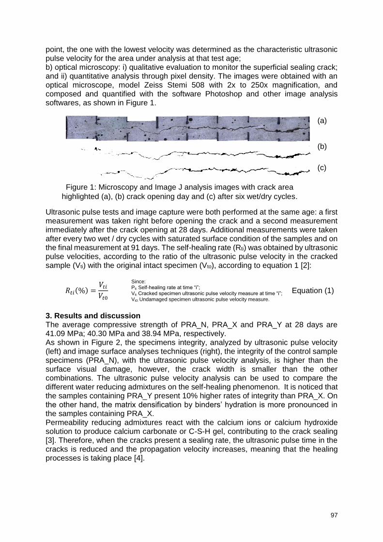
97
point, the one with the lowest velocity was determined as the characteristic ultrasonic pulse velocity for the area under analysis at that test age; b) optical microscopy: i) qualitative evaluation to monitor the superficial sealing crack; and ii) quantitative analysis through pixel density. The images were obtained with an optical microscope, model Zeiss Stemi 508 with 2x to 250x magnification, and composed and quantified with the software Photoshop and other image analysis softwares, as shown in Figure 1.
(a)
(b)
(c)
Figure 1: Microscopy and Image J analysis images with crack area
highlighted (a), (b) crack opening day and (c) after six wet/dry cycles.
Ultrasonic pulse tests and image capture were both performed at the same age: a first measurement was taken right before opening the crack and a second measurement immediately after the crack opening at 28 days. Additional measurements were taken after every two wet / dry cycles with saturated surface condition of the samples and on the final measurement at 91 days. The self-healing rate (Rti) was obtained by ultrasonic pulse velocities, according to the ratio of the ultrasonic pulse velocity in the cracked sample (Vti) with the original intact specimen (Vto), according to equation 1 [2]:
𝑅𝑡𝑖(%) =𝑉𝑡𝑖
𝑉𝑡0
Since: Pti: Self-healing rate at time “i”; Vti: Cracked specimen ultrasonic pulse velocity measure at time “i”; Vt0: Undamaged specimen ultrasonic pulse velocity measure.
Equation (1)
3. Results and discussion The average compressive strength of PRA_N, PRA_X and PRA_Y at 28 days are 41.09 MPa; 40.30 MPa and 38.94 MPa, respectively. As shown in Figure 2, the specimens integrity, analyzed by ultrasonic pulse velocity (left) and image surface analyses techniques (right), the integrity of the control sample specimens (PRA_N), with the ultrasonic pulse velocity analysis, is higher than the surface visual damage, however, the crack width is smaller than the other combinations. The ultrasonic pulse velocity analysis can be used to compare the different water reducing admixtures on the self-healing phenomenon. It is noticed that the samples containing PRA_Y present 10% higher rates of integrity than PRA_X. On the other hand, the matrix densification by binders’ hydration is more pronounced in the samples containing PRA_X. Permeability reducing admixtures react with the calcium ions or calcium hydroxide solution to produce calcium carbonate or C-S-H gel, contributing to the crack sealing [3]. Therefore, when the cracks present a sealing rate, the ultrasonic pulse time in the cracks is reduced and the propagation velocity increases, meaning that the healing processes is taking place [4].
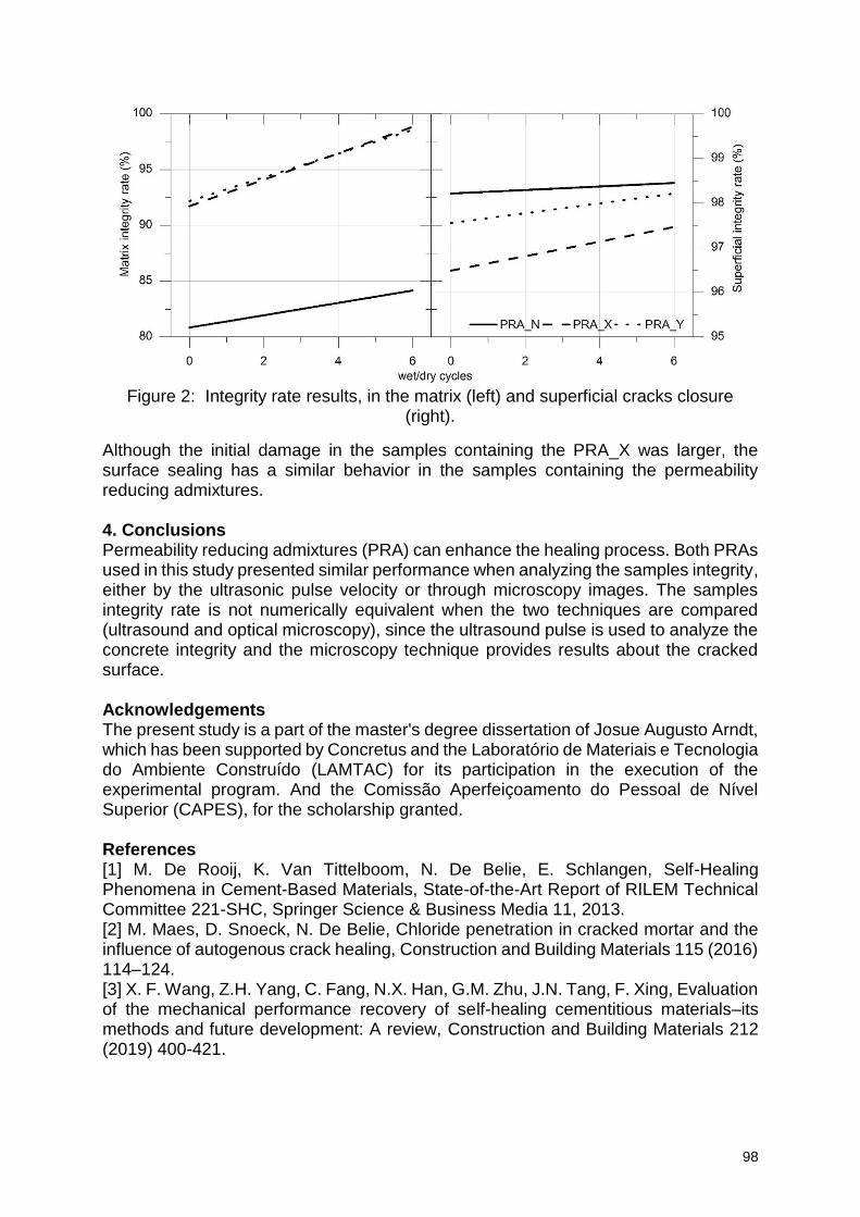
98
Figure 2: Integrity rate results, in the matrix (left) and superficial cracks closure
(right).
Although the initial damage in the samples containing the PRA_X was larger, the surface sealing has a similar behavior in the samples containing the permeability reducing admixtures. 4. Conclusions Permeability reducing admixtures (PRA) can enhance the healing process. Both PRAs used in this study presented similar performance when analyzing the samples integrity, either by the ultrasonic pulse velocity or through microscopy images. The samples integrity rate is not numerically equivalent when the two techniques are compared (ultrasound and optical microscopy), since the ultrasound pulse is used to analyze the concrete integrity and the microscopy technique provides results about the cracked surface. Acknowledgements The present study is a part of the master's degree dissertation of Josue Augusto Arndt, which has been supported by Concretus and the Laboratório de Materiais e Tecnologia do Ambiente Construído (LAMTAC) for its participation in the execution of the experimental program. And the Comissão Aperfeiçoamento do Pessoal de Nível Superior (CAPES), for the scholarship granted. References [1] M. De Rooij, K. Van Tittelboom, N. De Belie, E. Schlangen, Self-Healing Phenomena in Cement-Based Materials, State-of-the-Art Report of RILEM Technical Committee 221-SHC, Springer Science & Business Media 11, 2013. [2] M. Maes, D. Snoeck, N. De Belie, Chloride penetration in cracked mortar and the influence of autogenous crack healing, Construction and Building Materials 115 (2016) 114–124. [3] X. F. Wang, Z.H. Yang, C. Fang, N.X. Han, G.M. Zhu, J.N. Tang, F. Xing, Evaluation of the mechanical performance recovery of self-healing cementitious materials–its methods and future development: A review, Construction and Building Materials 212 (2019) 400-421.
99
[4] M. Ait Ouarabi, P. Antonaci, F. Boubenider, A. Gliozzi, M. Scalerandi, Ultrasonic monitoring of the interaction between cement matrix and alkaline silicate solution in self-healing systems, Materials, 10 1 (2017) 46.
100
Use of superabsorbent polymers to mitigate autogenous shrinkage in ultra-high performance concrete
L. De Meyst1, B. Debbaut1, M. Araújo1,2, K. Van Tittelboom1, S. Van Vlierberghe2, N.
De Belie1
1 Magnel Laboratory for Concrete Research, Ghent University, Tech Lane Ghent Science park, Campus A, Technologiepark-Zwijnaarde 60, 9052 Ghent, Belgium – email: [email protected]; [email protected]; [email protected]; [email protected]; [email protected]; 2 Polymer Chemistry and Biomaterials Group, Centre of Macromolecular Chemistry (CMaC), Ghent University, Krijgslaan 281, Building S4-bis, 9000 Ghent, Belgium – email: [email protected]
Abstract Ultra-high performance concrete (UHPC) with low w/c-ratio is very prone to the formation of cracks due to autogenous shrinkage. These cracks can lead to a decreased durability of the concrete, resulting in higher maintenance and/or repair costs in the future. Superabsorbent polymers (SAPs) can be added to cementitious materials to provide internal curing and as a result reduce or even mitigate this autogenous shrinkage. In this paper, two different types of SAPs were added to cement paste to see their influence on mitigating autogenous shrinkage. One SAP is a commercially available SAP whereas the other SAP is especially developed within the framework of the LORCENIS project by the company ChemStream, with the aim to mitigate autogenous shrinkage and induce self-healing of cracks. The SAPs from ChemStream were based on a copolymerization of sodium vinyl sulfonate (SVS) with 2-acryloylamino-2-methyl-propane-1-sulfonate (NaAMPS) and contained 1.0 mol% N,N’-methylenebisacrylamide (MBA) with respect to the monomer as cross-linker. The commercial SAP from BASF was based on poly(acrylamide-co-acrylic acid). In case SAPs were used, an additional fixed amount of water was added to mitigate autogenous shrinkage. The amount of SAPs used was determined based on their swelling capacity in cement filtrate and in order to obtain the same workability as the reference mixture. The amount of SAPs needed was in the range of 0.2-0.26 m% of the cement weight. To see whether the size of the SAPs plays a role in the efficiency of mitigating autogenous shrinkage, two average particle sizes, namely 40 and 100 µm, were tested. With the used amount of SAPs, a reduction or even complete counteraction of autogenous shrinkage was observed for the cement pastes. Keywords: Superabsorbent polymers (SAPs), autogenous shrinkage, corrugated tubes, internal curing 1. Introduction Ultra-high performance concrete (UHPC) is prone to autogenous shrinkage due to the low W/C-ratio (0.35 or lower) and as a result, the formation of cracks is inevitable. Due to a lack of free water the internal relative humidity (RH) will drop, resulting in self-desiccation when no external water source is present (RH < 100%) [1]. This may result in micro- and macro cracks which impair the strength, durability and aesthetics. Next to this, these cracks can create preferential pathways for water and gases, possibly containing harmful substances. These substances could induce steel corrosion, frost attack, chemical attack and internal expansive reactions resulting in a decreased
101
durability and structural integrity of the concrete structure [1]. Shrinkage of cementitious materials is divided in two stages: early age and later age shrinkage. Early age shrinkage, i.e. during the first 24 hours after mixing, is of great importance since at that age, the material has not yet gained substantial strength against crack formation. This results in micro-cracks which can widen over time due to later age shrinkage, i.e. beyond 24 hours after mixing [2], [3]. Autogenous shrinkage is a type of shrinkage which could have a negative effect on the cementitious material at early age [4]. Therefore, mitigating this type of shrinkage is of great importance. Internal curing can be applied to mitigate autogenous shrinkage. The basis of this method is the release of water in the cementitious matrix during cement hydration when the RH starts to drop and self-desiccation initiates. Superabsorbent polymers (SAPs) can be used as internal curing agents. Superabsorbent polymers are able to absorb up to 500 times their own weight in aqueous solutions, resulting in a swollen hydrogel. They are able to hold the liquid in their polymer network without dissolving [1]. In this paper, the effectiveness of different types and sizes of SAPs in mitigating autogenous shrinkage in cement paste is investigated. 2. Materials and methods In this paper, two different SAPs were tested to investigate their influence on the mitigation of shrinkage: one SAP produced by the company CHEMSTREAM (abbreviated as CS) and one commercially available SAP from the company BASF. The SAPs from ChemStream were based on a copolymerization of sodium vinyl sulfonate (SVS) with 2-acryloylamino-2-methyl-propane-1-sulfonate (NaAMPS) and contained 1.0 mol% N,N’-methylenebisacrylamide (MBA) with respect to the monomer as cross-linker. The commercial SAP from BASF was based on poly(acrylamide-co-acrylic acid), but no information on the amount nor type of the used cross-linker is available. The SAPs from ChemStream were ground with a centrifugal mill to mean
particle sizes d50 of 40 and 100 m (indicated in the code). The cement paste consisted of CEM I 52.5N (Holcim), superplasticizer Glenium 51 (35% active material) from BASF with a dosage of 0.42 m% (compared to cement) and one of the two types of SAPs. A W/C ratio of 0.3 was used. In case SAPs were used, an additional fixed amount of water based on literature (W/C = 0.054) [5] was added to mitigate autogenous shrinkage. The amount of SAPs used was determined based on their swelling capacity in cement filtrate as a starting value, which was adapted to obtain the same workability as for the reference mixture (i.e. 30 cm flow after 10 minutes). The final composition of the cement pastes is shown in Table 1. It can be seen that for the SAPs from ChemStream the final amount of SAPs is the same for both particle sizes (40 and 100 µm). For the commercial SAPs from BASF a smaller amount is needed, as their swelling capacity is somewhat higher, as will be discussed in the results section.
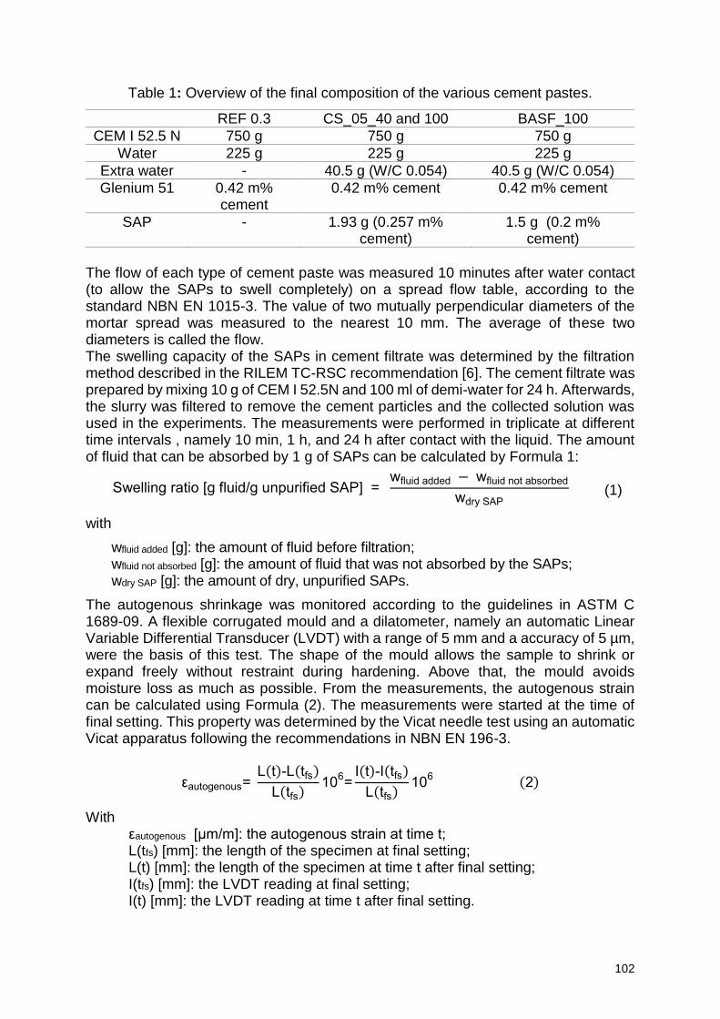
102
Table 1: Overview of the final composition of the various cement pastes.
REF 0.3 CS_05_40 and 100 BASF_100
CEM I 52.5 N 750 g 750 g 750 g
Water 225 g 225 g 225 g
Extra water - 40.5 g (W/C 0.054) 40.5 g (W/C 0.054)
Glenium 51 0.42 m% cement
0.42 m% cement 0.42 m% cement
SAP - 1.93 g (0.257 m% cement)
1.5 g (0.2 m% cement)
The flow of each type of cement paste was measured 10 minutes after water contact (to allow the SAPs to swell completely) on a spread flow table, according to the standard NBN EN 1015-3. The value of two mutually perpendicular diameters of the mortar spread was measured to the nearest 10 mm. The average of these two diameters is called the flow. The swelling capacity of the SAPs in cement filtrate was determined by the filtration method described in the RILEM TC-RSC recommendation [6]. The cement filtrate was prepared by mixing 10 g of CEM I 52.5N and 100 ml of demi-water for 24 h. Afterwards, the slurry was filtered to remove the cement particles and the collected solution was used in the experiments. The measurements were performed in triplicate at different time intervals , namely 10 min, 1 h, and 24 h after contact with the liquid. The amount of fluid that can be absorbed by 1 g of SAPs can be calculated by Formula 1:
Swelling ratio [g fluid/g unpurified SAP] = wfluid added − wfluid not absorbed
wdry SAP
(1)
with
wfluid added [g]: the amount of fluid before filtration; wfluid not absorbed [g]: the amount of fluid that was not absorbed by the SAPs; wdry SAP [g]: the amount of dry, unpurified SAPs.
The autogenous shrinkage was monitored according to the guidelines in ASTM C 1689-09. A flexible corrugated mould and a dilatometer, namely an automatic Linear Variable Differential Transducer (LVDT) with a range of 5 mm and a accuracy of 5 µm, were the basis of this test. The shape of the mould allows the sample to shrink or expand freely without restraint during hardening. Above that, the mould avoids moisture loss as much as possible. From the measurements, the autogenous strain can be calculated using Formula (2). The measurements were started at the time of final setting. This property was determined by the Vicat needle test using an automatic Vicat apparatus following the recommendations in NBN EN 196-3.
εautogenous= L(t)-L(tfs)
L(tfs)10
6=
I(t)-I(tfs)
L(tfs)10
6 (2)
With εautogenous [μm/m]: the autogenous strain at time t; L(tfs) [mm]: the length of the specimen at final setting; L(t) [mm]: the length of the specimen at time t after final setting; I(tfs) [mm]: the LVDT reading at final setting; I(t) [mm]: the LVDT reading at time t after final setting.
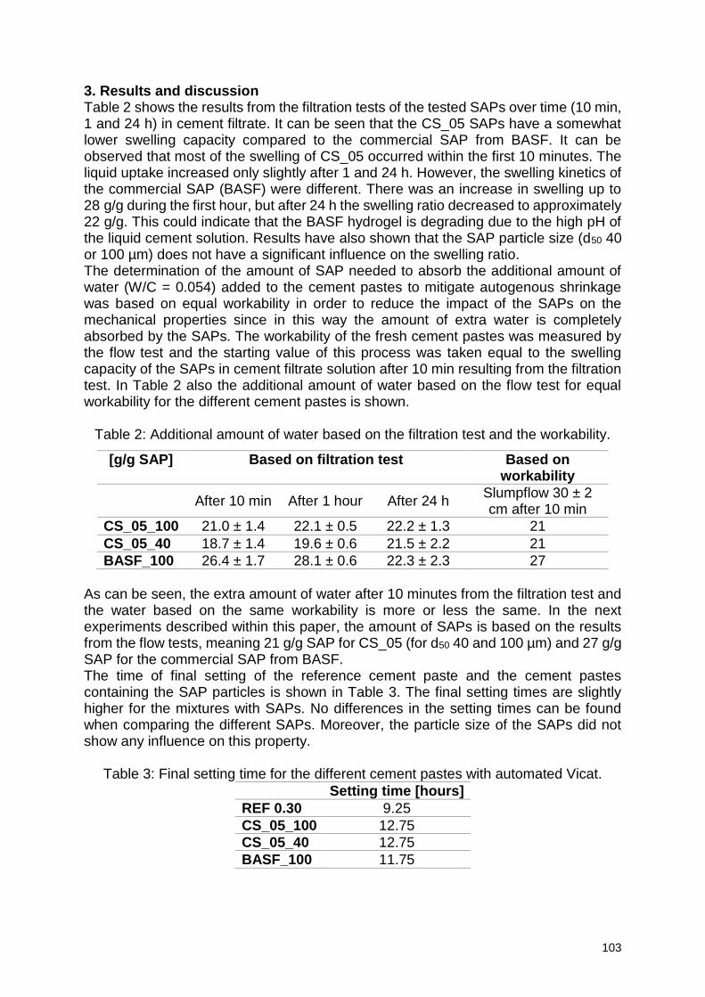
103
3. Results and discussion Table 2 shows the results from the filtration tests of the tested SAPs over time (10 min, 1 and 24 h) in cement filtrate. It can be seen that the CS_05 SAPs have a somewhat lower swelling capacity compared to the commercial SAP from BASF. It can be observed that most of the swelling of CS_05 occurred within the first 10 minutes. The liquid uptake increased only slightly after 1 and 24 h. However, the swelling kinetics of the commercial SAP (BASF) were different. There was an increase in swelling up to 28 g/g during the first hour, but after 24 h the swelling ratio decreased to approximately 22 g/g. This could indicate that the BASF hydrogel is degrading due to the high pH of the liquid cement solution. Results have also shown that the SAP particle size (d50 40 or 100 µm) does not have a significant influence on the swelling ratio. The determination of the amount of SAP needed to absorb the additional amount of water (W/C = 0.054) added to the cement pastes to mitigate autogenous shrinkage was based on equal workability in order to reduce the impact of the SAPs on the mechanical properties since in this way the amount of extra water is completely absorbed by the SAPs. The workability of the fresh cement pastes was measured by the flow test and the starting value of this process was taken equal to the swelling capacity of the SAPs in cement filtrate solution after 10 min resulting from the filtration test. In Table 2 also the additional amount of water based on the flow test for equal workability for the different cement pastes is shown.
Table 2: Additional amount of water based on the filtration test and the workability.
[g/g SAP] Based on filtration test Based on workability
After 10 min After 1 hour After 24 h Slumpflow 30 ± 2 cm after 10 min
CS_05_100 21.0 ± 1.4 22.1 ± 0.5 22.2 ± 1.3 21
CS_05_40 18.7 ± 1.4 19.6 ± 0.6 21.5 ± 2.2 21
BASF_100 26.4 ± 1.7 28.1 ± 0.6 22.3 ± 2.3 27
As can be seen, the extra amount of water after 10 minutes from the filtration test and the water based on the same workability is more or less the same. In the next experiments described within this paper, the amount of SAPs is based on the results from the flow tests, meaning 21 g/g SAP for CS_05 (for d50 40 and 100 µm) and 27 g/g SAP for the commercial SAP from BASF. The time of final setting of the reference cement paste and the cement pastes containing the SAP particles is shown in Table 3. The final setting times are slightly higher for the mixtures with SAPs. No differences in the setting times can be found when comparing the different SAPs. Moreover, the particle size of the SAPs did not show any influence on this property.
Table 3: Final setting time for the different cement pastes with automated Vicat. Setting time [hours]
REF 0.30 9.25
CS_05_100 12.75
CS_05_40 12.75
BASF_100 11.75
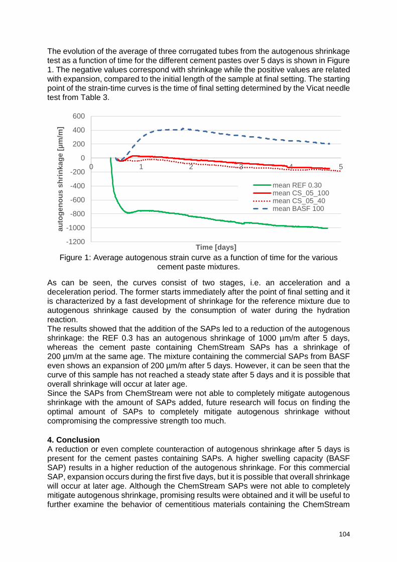
104
The evolution of the average of three corrugated tubes from the autogenous shrinkage test as a function of time for the different cement pastes over 5 days is shown in Figure 1. The negative values correspond with shrinkage while the positive values are related with expansion, compared to the initial length of the sample at final setting. The starting point of the strain-time curves is the time of final setting determined by the Vicat needle test from Table 3.
Figure 1: Average autogenous strain curve as a function of time for the various
cement paste mixtures.
As can be seen, the curves consist of two stages, i.e. an acceleration and a deceleration period. The former starts immediately after the point of final setting and it is characterized by a fast development of shrinkage for the reference mixture due to autogenous shrinkage caused by the consumption of water during the hydration reaction. The results showed that the addition of the SAPs led to a reduction of the autogenous shrinkage: the REF 0.3 has an autogenous shrinkage of 1000 µm/m after 5 days, whereas the cement paste containing ChemStream SAPs has a shrinkage of 200 µm/m at the same age. The mixture containing the commercial SAPs from BASF even shows an expansion of 200 µm/m after 5 days. However, it can be seen that the curve of this sample has not reached a steady state after 5 days and it is possible that overall shrinkage will occur at later age. Since the SAPs from ChemStream were not able to completely mitigate autogenous shrinkage with the amount of SAPs added, future research will focus on finding the optimal amount of SAPs to completely mitigate autogenous shrinkage without compromising the compressive strength too much. 4. Conclusion A reduction or even complete counteraction of autogenous shrinkage after 5 days is present for the cement pastes containing SAPs. A higher swelling capacity (BASF SAP) results in a higher reduction of the autogenous shrinkage. For this commercial SAP, expansion occurs during the first five days, but it is possible that overall shrinkage will occur at later age. Although the ChemStream SAPs were not able to completely mitigate autogenous shrinkage, promising results were obtained and it will be useful to further examine the behavior of cementitious materials containing the ChemStream
-1200
-1000
-800
-600
-400
-200
0
200
400
600
0 1 2 3 4 5
au
tog
en
ou
s s
hri
nka
ge
[µ
m/m
]
Time [days]
mean REF 0.30mean CS_05_100mean CS_05_40mean BASF 100
105
SAPs. The benefit of using ‘’in-house’’ developed SAPs (as the ones of ChemStream) compared to the use of commercially available SAPs is that the former offers the possibility of fine-tuning their properties in order to achieve a better or a desired performance. By for example varying the cross-linking degree of the ChemStream SAPs (and thus their swelling capacity), complete mitigation of autogenous shrinkage might be possible, and they may offer additional benefits for self-healing of cracks in concrete elements. Acknowledgements These results are part of a project that has received partial funding from the European Union's Horizon 2020 research and innovation program under grant agreement Nº685445 – LORCENIS and partial funding from the Research Foundation Flanders (FWO Vlaanderen) under project No.G.0A28.16. References [1] D. Snoeck, O.M. Jensen, N. De Belie, The influence of superabsorbent polymers on the autogenous shrinkage properties of cement pastes with supplementary cementitious materials, Cem. Concr. Res. 74 (2015) 59–67. doi:10.1016/j.cemconres.2015.03.020. [2] E.E. Holt, Early age autogenous shrinkage of concrete, VTT Publ. (2001) 2–184. [3] L. Wu, N. Farzadnia, C. Shi, Z. Zhang, H. Wang, Autogenous shrinkage of high performance concrete: A review, Constr. Build. Mater. 149 (2017). doi:10.1016/j.conbuildmat.2017.05.064. [4] L. Barcelo, M. Moranville, B. Clavaud, Autogenous shrinkage of concrete : a balance between autogenous swelling and self-desiccation, Cem. Concr. Res. 35 (2005) 177–183. doi:10.1016/j.cemconres.2004.05.050. [5] O.M. Jensen, P.F. Hansen, Water-entrained cement-based materials I. Principles and theoretical background, Cem. Concr. Res. 31 (2001) 647–654. doi:10.1016/S0008-8846(02)00737-8. [6] D. Snoeck, C. Schröfl, V. Mechtcherine, Recommendation of RILEM TC 260-RSC : testing sorption by superabsorbent polymers ( SAP ) prior to implementation in cement-based materials, 8 (2018). doi:10.1617/s11527-018-1242-8.
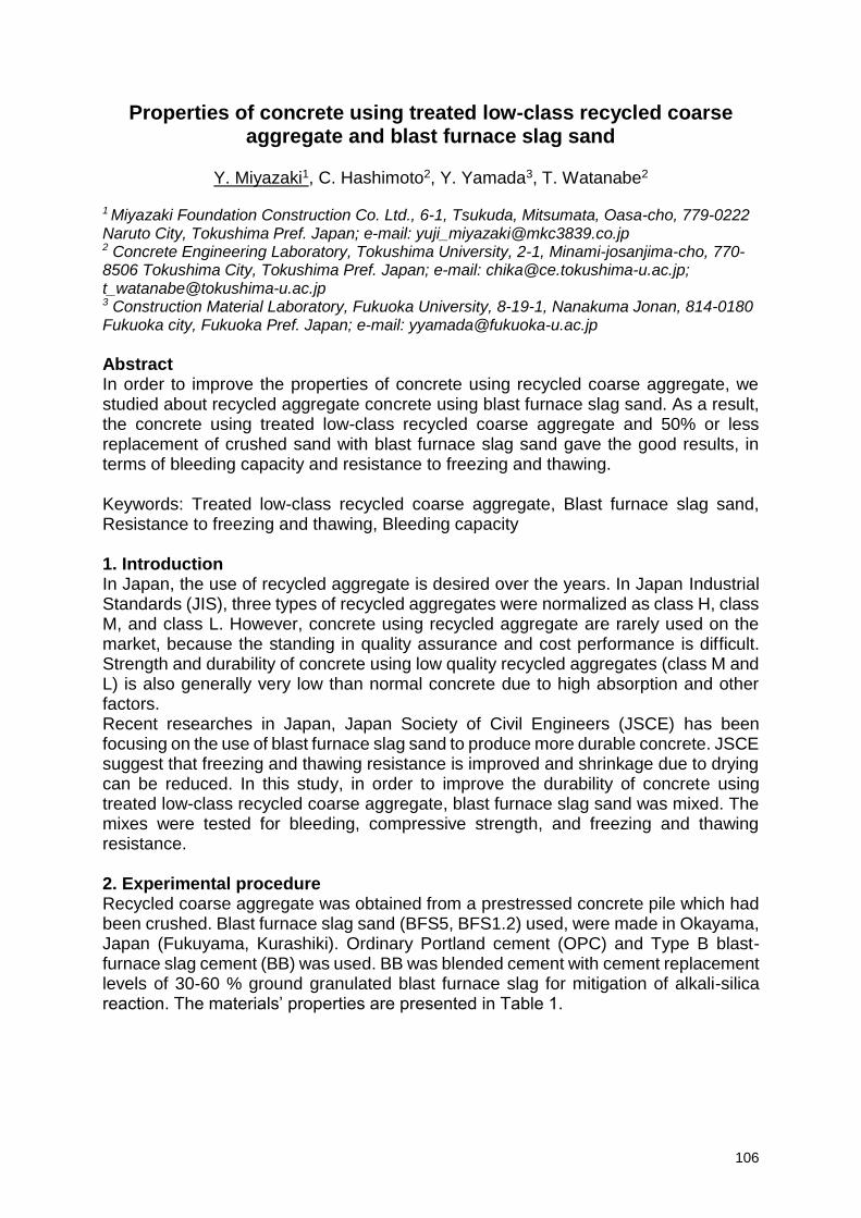
106
Properties of concrete using treated low-class recycled coarse aggregate and blast furnace slag sand
Y. Miyazaki1, C. Hashimoto2, Y. Yamada3, T. Watanabe2
1 Miyazaki Foundation Construction Co. Ltd., 6-1, Tsukuda, Mitsumata, Oasa-cho, 779-0222 Naruto City, Tokushima Pref. Japan; e-mail: [email protected] 2 Concrete Engineering Laboratory, Tokushima University, 2-1, Minami-josanjima-cho, 770-8506 Tokushima City, Tokushima Pref. Japan; e-mail: [email protected]; [email protected] 3 Construction Material Laboratory, Fukuoka University, 8-19-1, Nanakuma Jonan, 814-0180 Fukuoka city, Fukuoka Pref. Japan; e-mail: [email protected]
Abstract In order to improve the properties of concrete using recycled coarse aggregate, we studied about recycled aggregate concrete using blast furnace slag sand. As a result, the concrete using treated low-class recycled coarse aggregate and 50% or less replacement of crushed sand with blast furnace slag sand gave the good results, in terms of bleeding capacity and resistance to freezing and thawing. Keywords: Treated low-class recycled coarse aggregate, Blast furnace slag sand, Resistance to freezing and thawing, Bleeding capacity 1. Introduction In Japan, the use of recycled aggregate is desired over the years. In Japan Industrial Standards (JIS), three types of recycled aggregates were normalized as class H, class M, and class L. However, concrete using recycled aggregate are rarely used on the market, because the standing in quality assurance and cost performance is difficult. Strength and durability of concrete using low quality recycled aggregates (class M and L) is also generally very low than normal concrete due to high absorption and other factors. Recent researches in Japan, Japan Society of Civil Engineers (JSCE) has been focusing on the use of blast furnace slag sand to produce more durable concrete. JSCE suggest that freezing and thawing resistance is improved and shrinkage due to drying can be reduced. In this study, in order to improve the durability of concrete using treated low-class recycled coarse aggregate, blast furnace slag sand was mixed. The mixes were tested for bleeding, compressive strength, and freezing and thawing resistance. 2. Experimental procedure Recycled coarse aggregate was obtained from a prestressed concrete pile which had been crushed. Blast furnace slag sand (BFS5, BFS1.2) used, were made in Okayama, Japan (Fukuyama, Kurashiki). Ordinary Portland cement (OPC) and Type B blast-furnace slag cement (BB) was used. BB was blended cement with cement replacement levels of 30-60 % ground granulated blast furnace slag for mitigation of alkali-silica reaction. The materials’ properties are presented in Table 1.
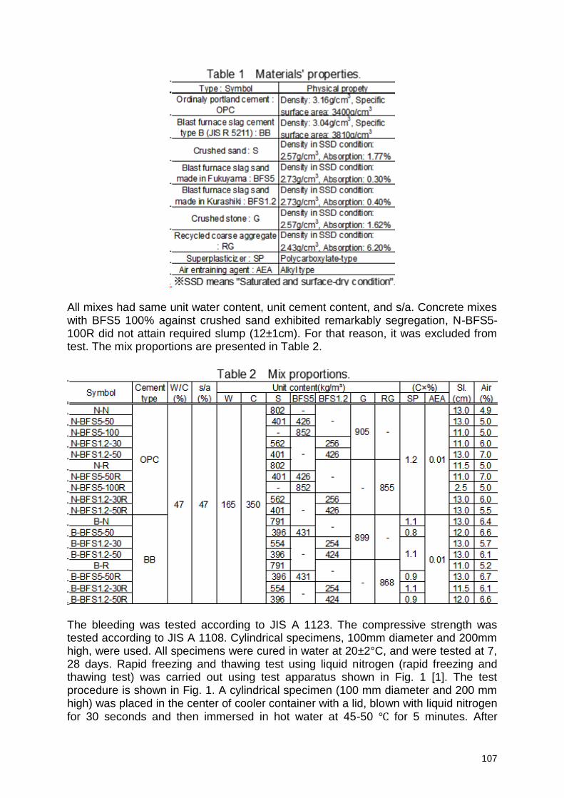
107
All mixes had same unit water content, unit cement content, and s/a. Concrete mixes with BFS5 100% against crushed sand exhibited remarkably segregation, N-BFS5-100R did not attain required slump (12±1cm). For that reason, it was excluded from test. The mix proportions are presented in Table 2.
The bleeding was tested according to JIS A 1123. The compressive strength was tested according to JIS A 1108. Cylindrical specimens, 100mm diameter and 200mm high, were used. All specimens were cured in water at 20±2°C, and were tested at 7, 28 days. Rapid freezing and thawing test using liquid nitrogen (rapid freezing and thawing test) was carried out using test apparatus shown in Fig. 1 [1]. The test procedure is shown in Fig. 1. A cylindrical specimen (100 mm diameter and 200 mm high) was placed in the center of cooler container with a lid, blown with liquid nitrogen for 30 seconds and then immersed in hot water at 45-50 for 5 minutes. After
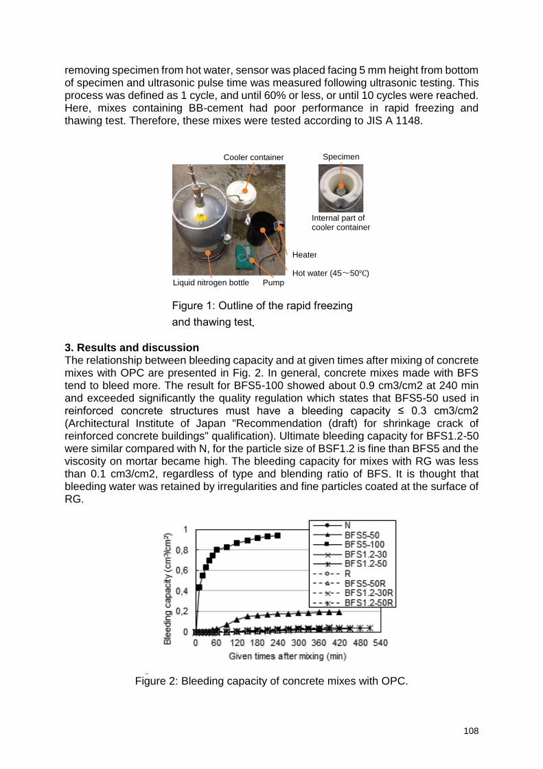
108
removing specimen from hot water, sensor was placed facing 5 mm height from bottom of specimen and ultrasonic pulse time was measured following ultrasonic testing. This process was defined as 1 cycle, and until 60% or less, or until 10 cycles were reached. Here, mixes containing BB-cement had poor performance in rapid freezing and thawing test. Therefore, these mixes were tested according to JIS A 1148. 3. Results and discussion The relationship between bleeding capacity and at given times after mixing of concrete mixes with OPC are presented in Fig. 2. In general, concrete mixes made with BFS tend to bleed more. The result for BFS5-100 showed about 0.9 cm3/cm2 at 240 min and exceeded significantly the quality regulation which states that BFS5-50 used in reinforced concrete structures must have a bleeding capacity ≤ 0.3 cm3/cm2 (Architectural Institute of Japan "Recommendation (draft) for shrinkage crack of reinforced concrete buildings" qualification). Ultimate bleeding capacity for BFS1.2-50 were similar compared with N, for the particle size of BSF1.2 is fine than BFS5 and the viscosity on mortar became high. The bleeding capacity for mixes with RG was less than 0.1 cm3/cm2, regardless of type and blending ratio of BFS. It is thought that bleeding water was retained by irregularities and fine particles coated at the surface of RG.
Figure 2: Bleeding capacity of concrete mixes with OPC.
Figure 1: Outline of the rapid freezing
and thawing test.
Pump Liquid nitrogen bottle Hot water (45~50)
Cooler container Specimen
Internal part of cooler container
Heater
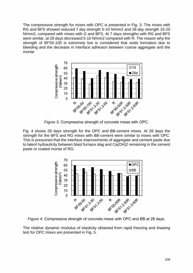
109
The compressive strength for mixes with OPC is presented in Fig. 3. The mixes with RG and BFS showed reduced 7 day strength 5-10 N/mm2 and 28 day strength 15-20 N/mm2, compared with mixes with G and BFS. At 7 days strengths with RG and BFS were similar, at 28 days decreased 5-10 N/mm2 compared with R. The reason why the strength of BFS5-100 is extremely low is considered that voids formation due to bleeding and the decrease in interface adhesion between coarse aggregate and the mortar.
Figure 3: Compressive strength of concrete mixes with OPC.
Fig. 4 shows 28 days strength for the OPC and BB-cement mixes. At 28 days the strength for the BFS and RG mixes with BB-cement were similar to mixes with OPC. This is presumed that the interface improvements of aggregate and cement paste due to latent hydraulicity between blast furnace slag and Ca(OH)2 remaining in the cement paste or coated mortar of RG.
Figure 4: Compressive strength of concrete mixes with OPC and BB at 28 days.
The relative dynamic modulus of elasticity obtained from rapid freezing and thawing test for OPC mixes are presented in Fig. 5.
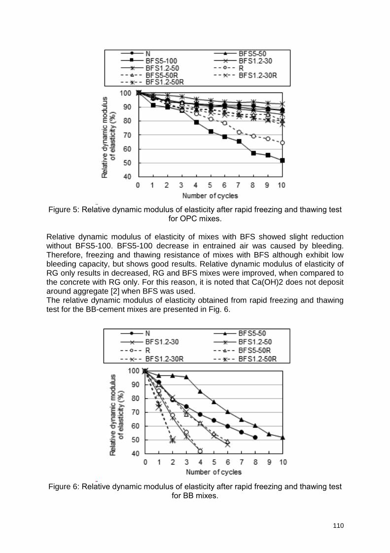
110
Figure 5: Relative dynamic modulus of elasticity after rapid freezing and thawing test
for OPC mixes.
Relative dynamic modulus of elasticity of mixes with BFS showed slight reduction without BFS5-100. BFS5-100 decrease in entrained air was caused by bleeding. Therefore, freezing and thawing resistance of mixes with BFS although exhibit low bleeding capacity, but shows good results. Relative dynamic modulus of elasticity of RG only results in decreased, RG and BFS mixes were improved, when compared to the concrete with RG only. For this reason, it is noted that Ca(OH)2 does not deposit around aggregate [2] when BFS was used. The relative dynamic modulus of elasticity obtained from rapid freezing and thawing test for the BB-cement mixes are presented in Fig. 6.
Figure 6: Relative dynamic modulus of elasticity after rapid freezing and thawing test
for BB mixes.
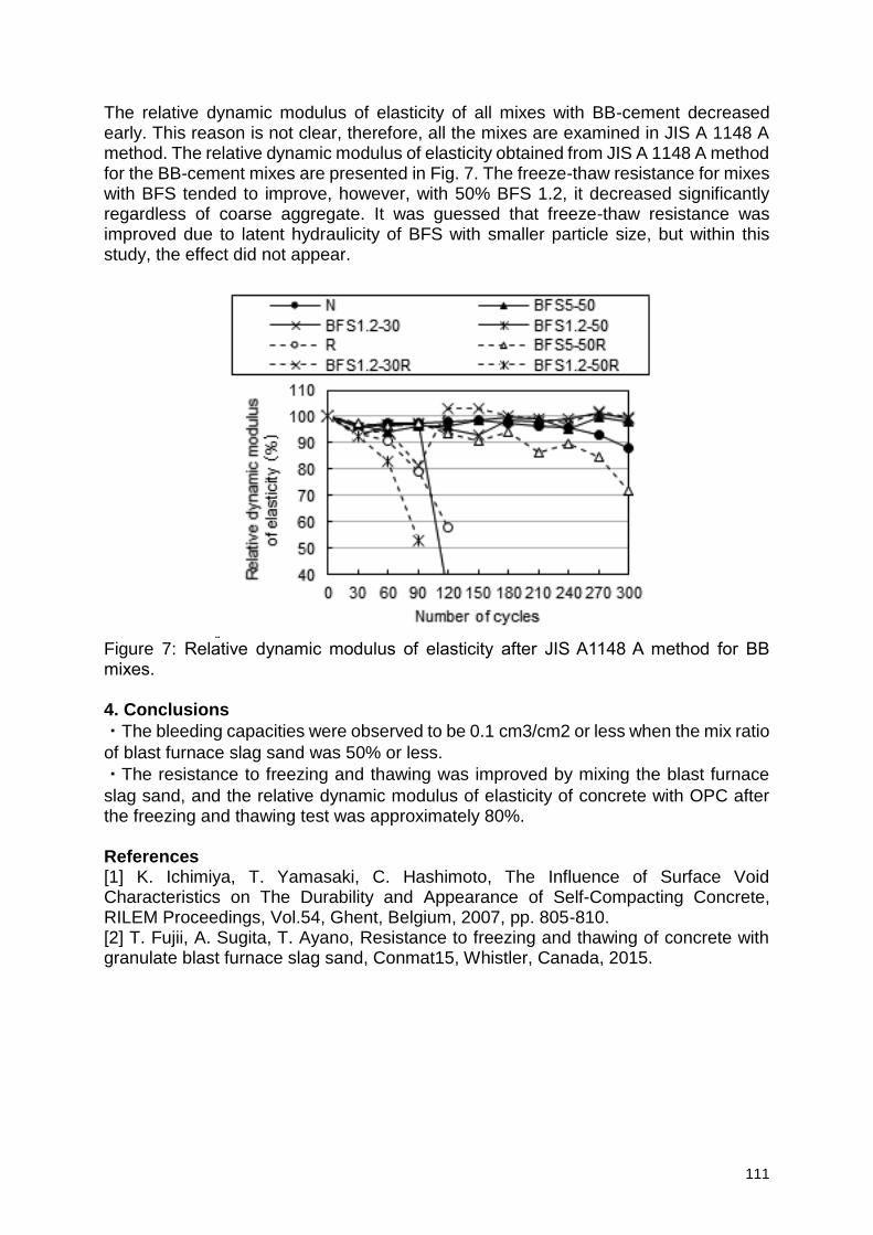
111
The relative dynamic modulus of elasticity of all mixes with BB-cement decreased early. This reason is not clear, therefore, all the mixes are examined in JIS A 1148 A method. The relative dynamic modulus of elasticity obtained from JIS A 1148 A method for the BB-cement mixes are presented in Fig. 7. The freeze-thaw resistance for mixes with BFS tended to improve, however, with 50% BFS 1.2, it decreased significantly regardless of coarse aggregate. It was guessed that freeze-thaw resistance was improved due to latent hydraulicity of BFS with smaller particle size, but within this study, the effect did not appear.
Figure 7: Relative dynamic modulus of elasticity after JIS A1148 A method for BB mixes. 4. Conclusions
・The bleeding capacities were observed to be 0.1 cm3/cm2 or less when the mix ratio
of blast furnace slag sand was 50% or less.
・The resistance to freezing and thawing was improved by mixing the blast furnace
slag sand, and the relative dynamic modulus of elasticity of concrete with OPC after the freezing and thawing test was approximately 80%. References [1] K. Ichimiya, T. Yamasaki, C. Hashimoto, The Influence of Surface Void Characteristics on The Durability and Appearance of Self-Compacting Concrete, RILEM Proceedings, Vol.54, Ghent, Belgium, 2007, pp. 805-810. [2] T. Fujii, A. Sugita, T. Ayano, Resistance to freezing and thawing of concrete with granulate blast furnace slag sand, Conmat15, Whistler, Canada, 2015.
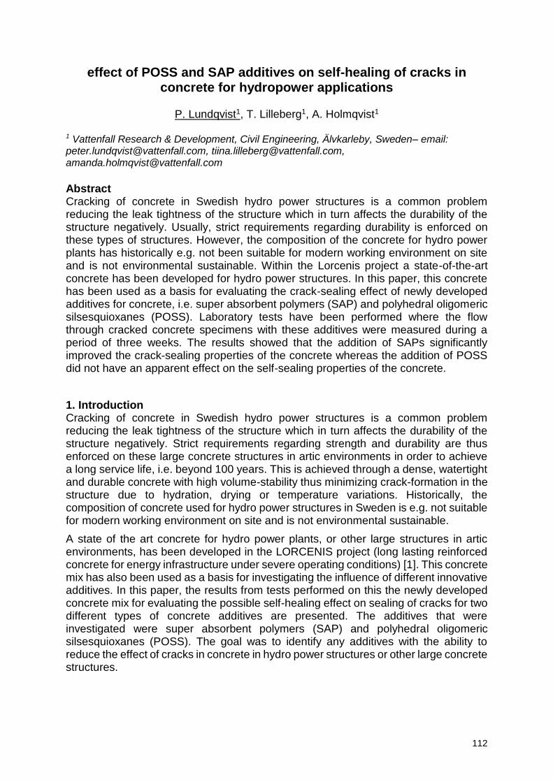
112
effect of POSS and SAP additives on self-healing of cracks in concrete for hydropower applications
P. Lundqvist1, T. Lilleberg1, A. Holmqvist1
1 Vattenfall Research & Development, Civil Engineering, Älvkarleby, Sweden– email: [email protected], [email protected], [email protected]
Abstract Cracking of concrete in Swedish hydro power structures is a common problem reducing the leak tightness of the structure which in turn affects the durability of the structure negatively. Usually, strict requirements regarding durability is enforced on these types of structures. However, the composition of the concrete for hydro power plants has historically e.g. not been suitable for modern working environment on site and is not environmental sustainable. Within the Lorcenis project a state-of-the-art concrete has been developed for hydro power structures. In this paper, this concrete has been used as a basis for evaluating the crack-sealing effect of newly developed additives for concrete, i.e. super absorbent polymers (SAP) and polyhedral oligomeric silsesquioxanes (POSS). Laboratory tests have been performed where the flow through cracked concrete specimens with these additives were measured during a period of three weeks. The results showed that the addition of SAPs significantly improved the crack-sealing properties of the concrete whereas the addition of POSS did not have an apparent effect on the self-sealing properties of the concrete.
1. Introduction Cracking of concrete in Swedish hydro power structures is a common problem reducing the leak tightness of the structure which in turn affects the durability of the structure negatively. Strict requirements regarding strength and durability are thus enforced on these large concrete structures in artic environments in order to achieve a long service life, i.e. beyond 100 years. This is achieved through a dense, watertight and durable concrete with high volume-stability thus minimizing crack-formation in the structure due to hydration, drying or temperature variations. Historically, the composition of concrete used for hydro power structures in Sweden is e.g. not suitable for modern working environment on site and is not environmental sustainable.
A state of the art concrete for hydro power plants, or other large structures in artic environments, has been developed in the LORCENIS project (long lasting reinforced concrete for energy infrastructure under severe operating conditions) [1]. This concrete mix has also been used as a basis for investigating the influence of different innovative additives. In this paper, the results from tests performed on this the newly developed concrete mix for evaluating the possible self-healing effect on sealing of cracks for two different types of concrete additives are presented. The additives that were investigated were super absorbent polymers (SAP) and polyhedral oligomeric silsesquioxanes (POSS). The goal was to identify any additives with the ability to reduce the effect of cracks in concrete in hydro power structures or other large concrete structures.
113
2. Materials and methods The state-of-the-art concrete mix that was developed earlier was used as a reference in the tests in this paper. The mix design was based on a portland cement (CEM I 42.5 R SR0) with an addition of class F fly ash (k-value of 0.4), see table 1 for the complete mix design. Those newly developed additives (within the Lorcenis project) whose effect was investigated were POSS and two types of SAPs. The POSS additive was manufactured by SINTEF in Norway and two types of SAPs were manufactured by the University of Athens (NTUA) in Greece and the company ChemStream in Belgium. Dosages of the additives were 2 % by weight of cement (bwoc) for POSS and 0.5 % bwoc and 0.25 % bwoc for the SAPs from NTUA and Chemstream, respectively. The SAP from ChemStream was named CSF0600250/05 with a particle size D50 = 40 µm. It was the self-curing and self-healing properties with the potential effect on sealing of cracks in concrete of these additives that was to investigated on the reference mix.
Table 1: Design for the concrete mix used as reference in the tests. Material Content / kg/m3
Cement, CEM I 42.5 R SR0 (Dyckerhoff) 310
Fly ash, class F 77.5
Water 170.5
Lime stone filler 54.3
Aggregate 0-32 1643.1
Air entrainer (solid), SIKA aersolid 7
Retarding additive, SIKA retard 0.2 % bwoc
Plasticizer, SIKA Viscocrete 3082 0.8 % bwoc
In the laboratory tests, the water flow through cracked concrete specimens subjected to a water head of 1000 mm were measured during a period of six weeks. Cylindrical specimens with a height of 200 mm and a diameter of 100 mm were used for the tests. After casting, the specimens were stored submerged in water and the tests were started at a concrete age of 56 days. A range of different crack widths were investigated in several test series where each test series was dedicated to a specific crack width. The cracks were either produced by sawing the specimens along the vertical axis or cracking the specimens similarly to a tensile splitting test. In order to produce cracks with a specific width, 10 mm wide spacers were placed along the vertical axis on the sawed surfaces. The two halves were then tied together, see figure 1. Crack widths of 0.05, 0,01 and 0.15 mm were tested. However, at the time of publication of this paper only the results from the tests on the specimens with a crack width of 0.05 mm were available, therefore only those results will be presented in this paper.
In figure 1 the test setup is shown, the specimens were placed in an hydraulic conductivity testing rig with a variable water head. In this test setup the water head was 1000 mm. The continuous flow through the specimens were collected in a separate reservoir and measured regularly during each test series. Each test series consisted of a total of twelve specimens, i.e. three specimens for each additive and the reference mix.
In addition to the hydraulic measurements the effect of the additives on the fresh properties, compressive strength and volume stability of the concrete mix was investigated. These tests have been performed in an earlier phase of the Lorcenis project.
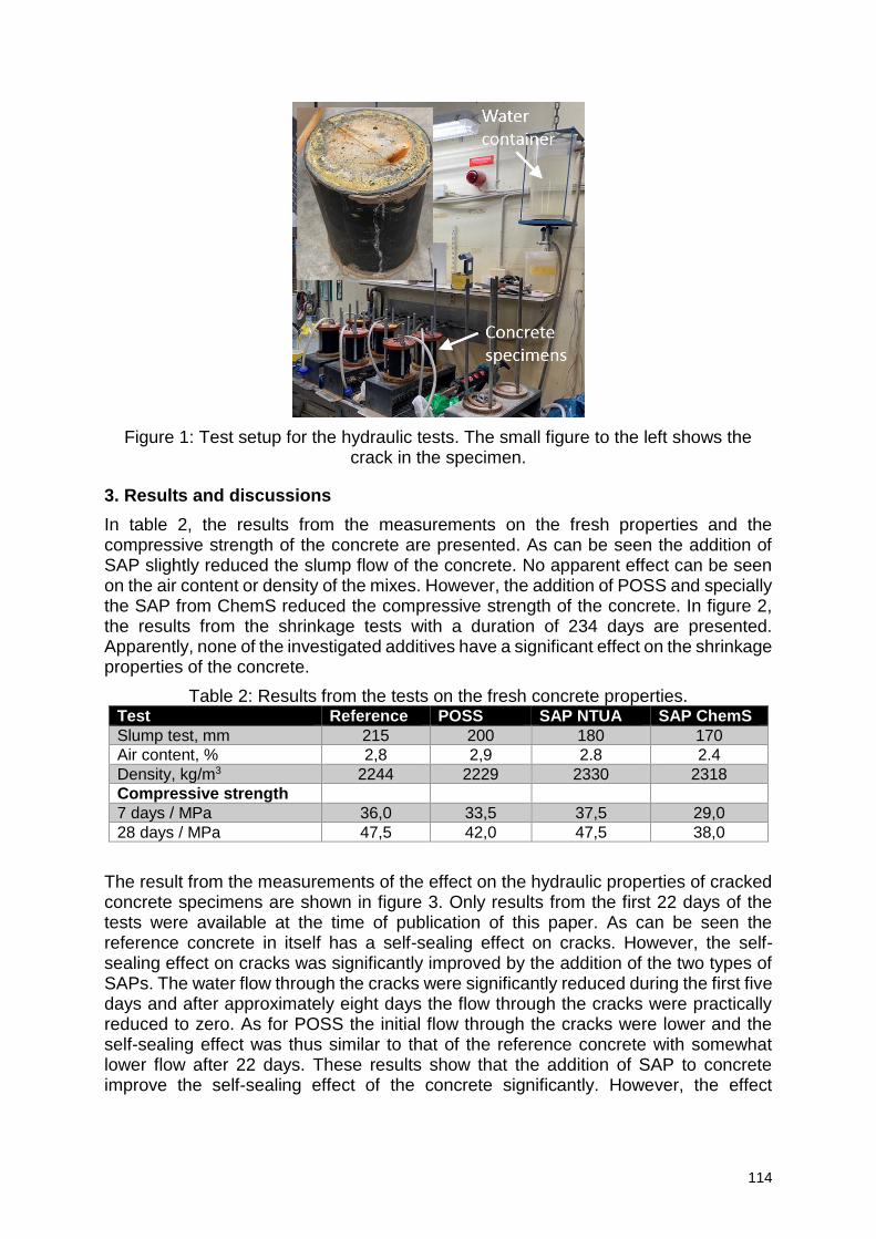
114
Figure 1: Test setup for the hydraulic tests. The small figure to the left shows the crack in the specimen.
3. Results and discussions
In table 2, the results from the measurements on the fresh properties and the compressive strength of the concrete are presented. As can be seen the addition of SAP slightly reduced the slump flow of the concrete. No apparent effect can be seen on the air content or density of the mixes. However, the addition of POSS and specially the SAP from ChemS reduced the compressive strength of the concrete. In figure 2, the results from the shrinkage tests with a duration of 234 days are presented. Apparently, none of the investigated additives have a significant effect on the shrinkage properties of the concrete.
Table 2: Results from the tests on the fresh concrete properties. Test Reference POSS SAP NTUA SAP ChemS
Slump test, mm 215 200 180 170
Air content, % 2,8 2,9 2.8 2.4
Density, kg/m3 2244 2229 2330 2318
Compressive strength
7 days / MPa 36,0 33,5 37,5 29,0
28 days / MPa 47,5 42,0 47,5 38,0
The result from the measurements of the effect on the hydraulic properties of cracked concrete specimens are shown in figure 3. Only results from the first 22 days of the tests were available at the time of publication of this paper. As can be seen the reference concrete in itself has a self-sealing effect on cracks. However, the self-sealing effect on cracks was significantly improved by the addition of the two types of SAPs. The water flow through the cracks were significantly reduced during the first five days and after approximately eight days the flow through the cracks were practically reduced to zero. As for POSS the initial flow through the cracks were lower and the self-sealing effect was thus similar to that of the reference concrete with somewhat lower flow after 22 days. These results show that the addition of SAP to concrete improve the self-sealing effect of the concrete significantly. However, the effect
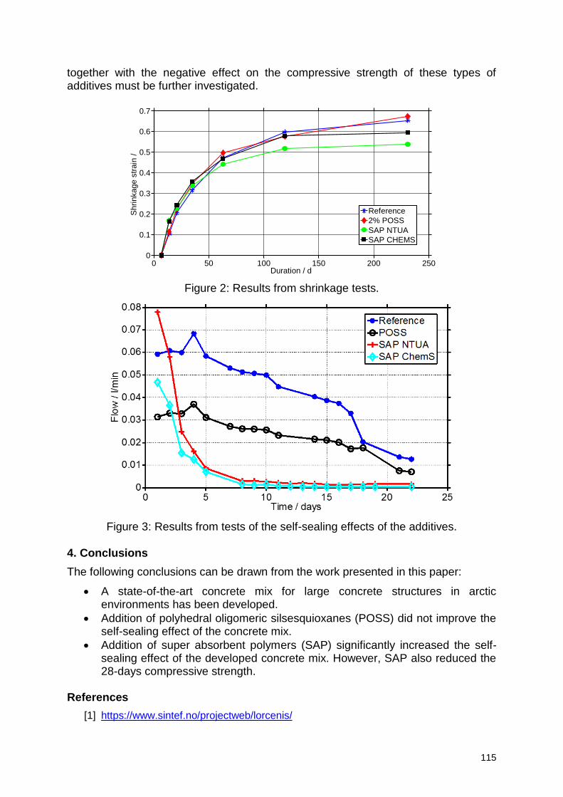
115
together with the negative effect on the compressive strength of these types of additives must be further investigated.
Figure 2: Results from shrinkage tests.
Figure 3: Results from tests of the self-sealing effects of the additives.
4. Conclusions
The following conclusions can be drawn from the work presented in this paper:
A state-of-the-art concrete mix for large concrete structures in arctic environments has been developed.
Addition of polyhedral oligomeric silsesquioxanes (POSS) did not improve the self-sealing effect of the concrete mix.
Addition of super absorbent polymers (SAP) significantly increased the self-sealing effect of the developed concrete mix. However, SAP also reduced the 28-days compressive strength.
References
[1] https://www.sintef.no/projectweb/lorcenis/
0 50 100 150 200 2500
0.1
0.2
0.3
0.4
0.5
0.6
0.7
Duration / d
Sh
rin
ka
ge
str
ain
/
Reference
2% POSS
SAP NTUA
SAP CHEMS
Session 3 Modelling and service life
prediction of concrete in extreme conditions
117
Experimental and numerical study of a vascular self-healing system for cementitious materials
Anthony Jefferson1
1 Cardiff School of Engineering, Cardiff University, CF24 3AA, UK – email: [email protected]
Abstract One of the challenges faced by those who carry out numerical research on self-healing cementitious materials is that the precise data needed to guide the development of a model, and subsequently validate its predictive capability, is often incomplete. To address this issue, a combined programme of experimental and numerical research has been undertaken at Cardiff University aimed at developing a comprehensive numerical model for a self-healing system based on vascular networks. The experiments undertaken to understand the behaviour of the system encompass the flow behaviour of healing agents in discrete and micro-cracked cementitious elements, the curing behaviour of a healing-agent in a cementitious environment, and multiple and overlapping mechanical damage/healing ‘events’. The numerical model derived from these experimental observations is a coupled finite element model that simulates all of the aforementioned aspects of behaviour. This model was validated using a separate set of experiments undertaken on structural elements but, importantly, the simulations only used the fundamental parameters derived from the characterisation tests. The accuracy and adequacy of both the experimental data and numerical model are critically assessed.
118
Providing structural engineers with a tool for the design of concrete coverage
P. Mainçon1, J. Psihogios2, Z. M. Mir3, D. Höche3, D. Dragatogiannis2,
C. A. Charitidis2
1 SINTEF Industry, R. Birkelands vei 2a, P.O.Box 4760 Torgarden, NO-7465 Trondheim, Norway – email: [email protected] 2 NTUA, School of Chemical Engineering, Iroon Polytechneiou 9, Zografou 157 80, Athens, Greece – email: [email protected]; [email protected]; [email protected]
3 HZG, Max-Planck-Straße 1, D-21502 Geesthacht, Germany – email: [email protected]; [email protected]
Abstract The process leading to spalling of concrete cover of steel reinforcements involves the transport of chemical species in concrete, chemical reactions in concrete, corrosion of the reainforcements (rebar), and finally microcracking and crack coalescence around the rebars. This paper presents the work to create a tool that captures these multi-physical multiscale processes with reasonable accuracy yet is simple enough for routine use in the design of concrete coverage. Keywords: Reinforcement corrosion; chloride diffusion; chloride binding additives; finite element analysis 1. Introduction The LORCENIS project aims making concrete structures longer lasting by introducing additives that control various aspects of the evolution of the chemistry of concrete over its lifetime. It is hence necessary to provide engineers with a way to estimate the effect of using various additives in concrete. The ambition is thus to create a numerical model that is simple to use, requires inputs that are available to engineers, fast to run on a standard laptop, and yet accounts with reasonable accuracy for phenomena occurring at different scales. To begin with, the capability to compute one given scenario was developed: during the service life of the concrete, chlorides provided by the seawater diffuse through the bulk of the concrete. Additives delay the diffusion by binding the chlorides (in addition to the binding of chlorides to the cementitious matrix). Eventually, the chlorides reach the surface of rebars closest to the outer surface of the concrete, depassivating it and initiating corrosion. The rate of corrosion is limited by the availability of oxygen, which is diffusing from the seawater through the bulk of the concrete. 2. Simplifications of the physics To ensure fast computations, all physical phenomena need to be "homogenized": concrete is considered as a continuum, with space-averaged properties for mechanics, transport and chemistry. Mechanical behavior of concrete includes microcracking under tensile strains, and the coalescence of micro cracks into macro cracks. In the present model, only linear elasticity is considered. This is a serious limitation (concrete under tension cannot be
119
modeled well) but also partly a strategy (when reinforcement bar expansion starts to cause microcracking, the useful lifetime is spent, and the analysis can be stopped). Transport of chlorides through the matrix occurs by flow of liquid in the percolation network, driven by drying/wetting/capillarity and by compression of concrete. Transport is also due to the diffusion of chlorides within the fluid, driven by concentration and temperature gradients, as well as migration (diffusion driven by a gradient of electrical potential). The percolation network is composed of the pore network, as well as microcracks, and large cracks. In the present model, we only consider the transport of chloride by diffusion in a fully wetted pore network, driven by gradients of concentration. This is modeled using Fick's law
= −𝐷 ∇ 𝐶𝐶𝑙−
Where is the flow of chloride, 𝐶𝐶𝑙− is the concentration referred to the volume of pore fluid (not to the total volume of concrete). The effective diffusivity coefficient 𝐷 can be obtained either experimentally or from computations that detail the geometry of the pore network. The same model is used for the diffusion of𝑂2. Capture (and release) of chlorides by additives occurs when adsorption sites in the additive release a 𝑁𝑂2
− or 𝑁𝑂3− ion and bind a chlorine ion.
The present model strongly resembles Langmuir's model for the adsorption of gasses: we consider the transition of a chlorine ion from a high-potential energy (in solution) over an activation threshold to a lower energy state (bound to the additive). By accounting for the probability of finding a site not occupied by chlorine, this leads to the kinetic law
𝑟+ = 𝐾𝑜+ 𝑒−
∆𝐺+
𝑅𝑇 𝐶𝐶𝑙− 𝑛 − 𝐶𝑡
𝑛
for the capture reaction, where 𝑟+ is the rate of the forward reaction 𝐾𝑜
+ is an attempt frequency, ∆𝐺+ is an activation energy, 𝑅 is the gas constant 𝑇 the temperature (in
Kelvins) , 𝐶𝑡 is the concentration of trapped chlorine, and (𝑛 − 𝐶𝑡) 𝑛⁄ is the probability of an absorption site being free of chlorine. The kinetic law of the release reaction is taken to be
𝑟− = 𝐾𝑜− 𝑒−
∆𝐺−
𝑅𝑇 𝐶𝑡 In practice, the binding reaction is going to be fast compared to other processes, so the user provides the binding energy ∆𝐺 [1,2]. The activation energy ∆𝐺+ is then taken as a small arbitrary fraction of ∆𝐺, and ∆𝐺− = ∆𝐺 + ∆𝐺+. Note that assuming detailed
balance (𝑟+ = 𝑟−) yields the Langmuir isotherm. Corrosion of the steel reinforcement is a complex network of electrochemical reactions, where natural variations combine with an unstable process to create pits. The local production of oxides will create local stress concentrations in the concrete.
120
In the present model, it is assumed that, when the pore concentration of chlorides exceeds a given threshold, the steel is depassivated [3]. Above the depassivation threshold the corrosion current is
𝑖𝑐𝑜𝑟𝑟 = 𝐴1𝑒𝑥𝑝 [𝐴2 + 𝐴3𝑙𝑜𝑔(𝐴4𝐶𝐶𝑙−) −𝐴5
𝑇− 𝐴6𝑒𝑥𝑝[𝐵1 − 𝐵2𝑙𝑜𝑔(1 + 𝐵3𝐶𝐶𝑙−)] + 𝐴7𝑡−𝐴8]
where 𝑇 and 𝑡 are respectively the temperature and time since the onset of corrosion, and 𝐴𝑖 's and 𝐵𝑖 's are model parameters. The corrosion process is considered uniform along and around the reinforcement bar. The corrosion products have a lower density than steel, thus the corroded rebar applies pressure on the surrounding concrete, eventually leading to cracking. 3. Solver In addition to simplifying the model of the physics, it is also necessary to create a specialized numerical solver, to obtain a fast solution process. The mesh needs to be as coarse as possible. Numerical models developed for research purposes use fine meshes with volume elements, both for the steel and the concrete. These meshes require large computing time to solve. In the present solver, the rebars are modeled using a bar finite element (with maybe 10 nodes per meter, instead of thousands of nodes). Strong gradients (of concentrations, of stresses) can occur in the vicinity of the bar. With normal finite element, which use polynomial interpolation, this would require a fine mesh. To avoid this, additional shape functions (varying in 1/𝑟 and in log 𝑟 away from the bar) are introduced, using an approach inspired from XFEM [4]. Time steps must be long – of the order of 100 steps for the lifetime of the structure. Yet the time scale of the chloride capture reaction is much shorter. To avoid the instabilities caused by long steps on rapid phenomena, the implicit Euler time-integration method is used, which is unconditionally stable. Reaction kinetics models can be called with implausible values (e.g. negative concentration), before the solution refinement process (Newton-Raphson iteration) converges. The reaction kinetic equations have been modified outside the plausible domain, to provide answers that will prevent a divergence of the iteration process. 4. Results and discussion The results of the analysis will be discussed in the authors' oral presentation, and an updated version of the paper will be made available. 5. Conclusion The model presented here is still too specialized to meet the requirements of engineers designing concrete structures. Still, it shows that combining physical insight to create relevant simplifications, and applying numerical techniques for fast solution, complicated multi-physical and multiscale processes can be captured with reasonable accuracy in fast numerical analysis.
121
Acknowledgements The research reported here was only possible thanks to the excellent collaboration with experimentalists and modelers within the LORCENIS project (EU research program Horizon2020 project 685445). References [1] Yuxuan Chen, Zhonghe Shui, Wei Chen, and Guowei Chen, Chloride binding of synthetic Ca-Al-NO3 LDHs in hardened cement paste. Construction and Building Materials, 93:1051–1058, 2015. [2] Liang Lv, Peide Sun, Zhengyu Gu, Hangeng Du, Xiangjun Pang, Xiaohong Tao, Rufeng Xu, and Lili Xu, Removal of chloride ion from aqueous solution by ZnAl-NO3 layered double hydroxides as anion-exchanger. Journal of Hazardous Materials, 161:1444–1449, 2009. [3] Dong Chen, Sankaran Mahadevan. Chloride-induced reinforcement corrosion and concrete cracking simulation. Cement and Concrete Composites, 30(3):227–238, March 2008. [4] Nicolas Moës, John Dolbow, Ted Belytschko, A finite element method for crack growth without remeshing. International Journal for Numerical Methods in Engineering. 46 (1): 131–150, 1999.
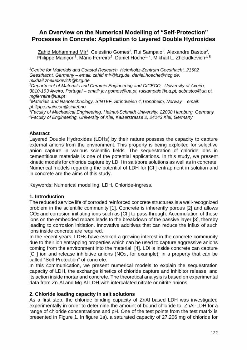
122
An Overview on the Numerical Modelling of “Self-Protection” Processes in Concrete: Application to Layered Double Hydroxides
Zahid Mohammad Mir1, Celestino Gomes2, Rui Sampaio2, Alexandre Bastos2, Philippe Mainçon3, Mário Ferreira2, Daniel Höche1, 4, Mikhail L. Zheludkevich1, 5
1Centre for Materials and Coastal Research, Helmholtz-Zentrum Geesthacht, 21502 Geesthacht, Germany – email: [email protected], [email protected], [email protected] 2Department of Materials and Ceramic Engineering and CICECO, University of Aveiro, 3810-193 Aveiro, Portugal – email: [email protected], [email protected], [email protected], [email protected] 3Materials and Nanotechnology, SINTEF, Strindveien 4,Trondheim, Norway – email: [email protected] 4Faculty of Mechanical Engineering, Helmut-Schmidt University, 22008 Hamburg, Germany 5Faculty of Engineering, University of Kiel, Kaiserstrasse 2, 24143 Kiel, Germany
Abstract Layered Double Hydroxides (LDHs) by their nature possess the capacity to capture external anions from the environment. This property is being exploited for selective anion capture in various scientific fields. The sequestration of chloride ions in cementitious materials is one of the potential applications. In this study, we present kinetic models for chloride capture by LDH in salt/pore solutions as well as in concrete. Numerical models regarding the potential of LDH for [Cl-] entrapment in solution and in concrete are the aims of this study. Keywords: Numerical modelling, LDH, Chloride-ingress. 1. Introduction The reduced service life of corroded reinforced concrete structures is a well-recognized problem in the scientific community [1]. Concrete is inherently porous [2] and allows CO2 and corrosion initiating ions such as [Cl-] to pass through. Accumulation of these ions on the embedded rebars leads to the breakdown of the passive layer [3], thereby leading to corrosion initiation. Innovative additives that can reduce the influx of such ions inside concrete are required. In the recent years, LDHs have evoked a growing interest in the concrete community due to their ion entrapping properties which can be used to capture aggressive anions coming from the environment into the material [4]. LDHs inside concrete can capture [Cl-] ion and release inhibitive anions (NO2
-, for example), in a property that can be called “Self-Protection” of concrete. In this communication, we present numerical models to explain the sequestration capacity of LDH, the exchange kinetics of chloride capture and inhibitor release, and its action inside mortar and concrete. The theoretical analysis is based on experimental data from Zn-Al and Mg-Al LDH with intercalated nitrate or nitrite anions.
2. Chloride loading capacity in salt solutions As a first step, the chloride binding capacity of ZnAl based LDH was investigated experimentally in order to determine the amount of bound chloride to ZnAl-LDH for a range of chloride concentrations and pH. One of the test points from the test matrix is presented in Figure 1. In figure 1a), a saturated capacity of 27.206 mg of chloride for
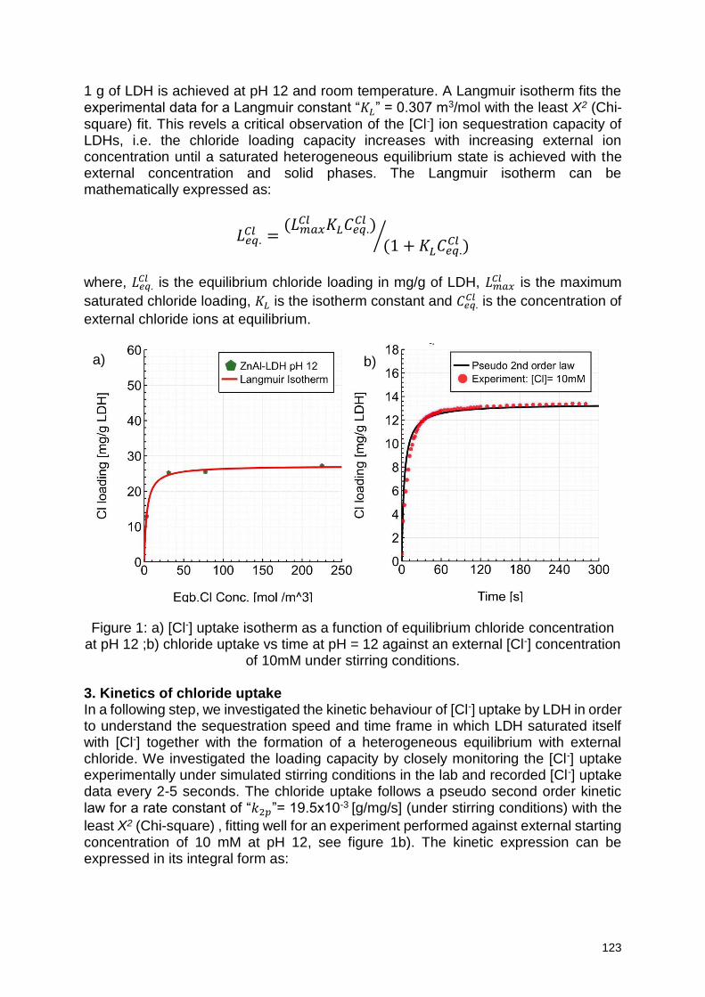
123
1 g of LDH is achieved at pH 12 and room temperature. A Langmuir isotherm fits the experimental data for a Langmuir constant “𝐾𝐿
” = 0.307 m3/mol with the least X2 (Chi-square) fit. This revels a critical observation of the [Cl-] ion sequestration capacity of LDHs, i.e. the chloride loading capacity increases with increasing external ion concentration until a saturated heterogeneous equilibrium state is achieved with the external concentration and solid phases. The Langmuir isotherm can be mathematically expressed as:
𝐿𝑒𝑞.𝐶𝑙 =
(𝐿𝑚𝑎𝑥𝐶𝑙 𝐾𝐿
𝐶𝑒𝑞.𝐶𝑙 )
(1 + 𝐾𝐿 𝐶𝑒𝑞.
𝐶𝑙 )⁄
where, 𝐿𝑒𝑞.𝐶𝑙 is the equilibrium chloride loading in mg/g of LDH, 𝐿𝑚𝑎𝑥
𝐶𝑙 is the maximum
saturated chloride loading, 𝐾𝐿 is the isotherm constant and 𝐶𝑒𝑞.
𝐶𝑙 is the concentration of
external chloride ions at equilibrium.
Figure 1: a) [Cl-] uptake isotherm as a function of equilibrium chloride concentration
at pH 12 ;b) chloride uptake vs time at pH = 12 against an external [Cl-] concentration of 10mM under stirring conditions.
3. Kinetics of chloride uptake In a following step, we investigated the kinetic behaviour of [Cl-] uptake by LDH in order to understand the sequestration speed and time frame in which LDH saturated itself with [Cl-] together with the formation of a heterogeneous equilibrium with external chloride. We investigated the loading capacity by closely monitoring the [Cl-] uptake experimentally under simulated stirring conditions in the lab and recorded [Cl-] uptake data every 2-5 seconds. The chloride uptake follows a pseudo second order kinetic law for a rate constant of “𝑘2𝑝”= 19.5x10⁻³ [g/mg/s] (under stirring conditions) with the
least X2 (Chi-square) , fitting well for an experiment performed against external starting concentration of 10 mM at pH 12, see figure 1b). The kinetic expression can be expressed in its integral form as:
a) b)
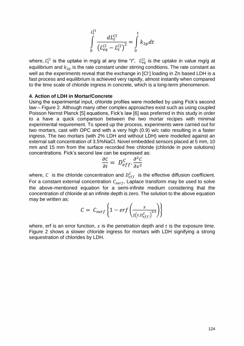
124
∫𝑑𝐿𝑡
𝐶𝑙
(𝐿𝑒𝑞𝐶𝑙 − 𝐿𝑡
𝐶𝑙)2 = ∫ 𝑘2𝑝𝑑𝑡
𝑡
0
𝐿𝑡𝐶𝑙
0
where, 𝐿𝑡𝐶𝑙 is the uptake in mg/g at any time “t”, 𝐿𝑒𝑞
𝐶𝑙 is the uptake in value mg/g at
equilibrium and 𝑘2𝑝 is the rate constant under stirring conditions. The rate constant as
well as the experiments reveal that the exchange in [Cl-] loading in Zn based LDH is a fast process and equilibrium is achieved very rapidly, almost instantly when compared to the time scale of chloride ingress in concrete, which is a long-term phenomenon.
4. Action of LDH in Mortar/Concrete Using the experimental input, chloride profiles were modelled by using Fick’s second law – Figure 2. Although many other complex approaches exist such as using coupled Poisson Nernst Planck [5] equations, Fick’s law [6] was preferred in this study in order to a have a quick comparison between the two mortar recipes with minimal experimental requirement. To speed up the process, experiments were carried out for two mortars, cast with OPC and with a very high (0.9) w/c ratio resulting in a faster ingress. The two mortars (with 2% LDH and without LDH) were modelled against an external salt concentration of 3.5%NaCl. Novel embedded sensors placed at 5 mm, 10 mm and 15 mm from the surface recorded free chloride (chloride in pore solutions) concentrations. Fick’s second law can be expressed as:
𝜕𝐶
𝜕𝑡= 𝐷𝑒𝑓𝑓
𝐶 .𝜕2𝐶
𝜕𝑥2
where, 𝐶 is the chloride concentration and 𝐷𝑒𝑓𝑓𝐶 is the effective diffusion coefficient.
For a constant external concentration 𝐶𝑠𝑢𝑟𝑓, Laplace transform may be used to solve
the above-mentioned equation for a semi-infinite medium considering that the concentration of chloride at an infinite depth is zero. The solution to the above equation may be written as:
𝐶 = 𝐶𝑠𝑢𝑟𝑓 1 − 𝑒𝑟𝑓 (𝑥
2(𝑡.𝐷𝑒𝑓𝑓𝐶 .)
0.5)
where, erf is an error function, 𝑥 is the penetration depth and 𝑡 is the exposure time. Figure 2 shows a slower chloride ingress for mortars with LDH signifying a strong sequestration of chlorides by LDH.
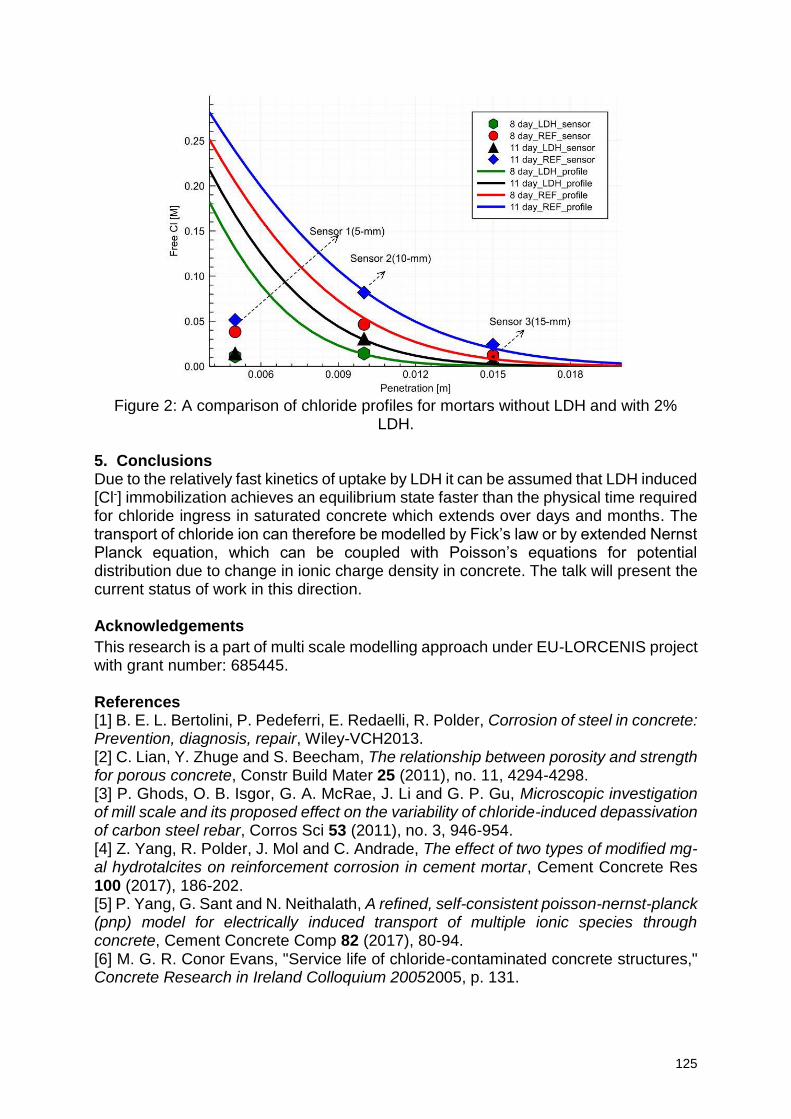
125
Figure 2: A comparison of chloride profiles for mortars without LDH and with 2%
LDH. 5. Conclusions Due to the relatively fast kinetics of uptake by LDH it can be assumed that LDH induced [Cl-] immobilization achieves an equilibrium state faster than the physical time required for chloride ingress in saturated concrete which extends over days and months. The transport of chloride ion can therefore be modelled by Fick’s law or by extended Nernst Planck equation, which can be coupled with Poisson’s equations for potential distribution due to change in ionic charge density in concrete. The talk will present the current status of work in this direction. Acknowledgements
This research is a part of multi scale modelling approach under EU-LORCENIS project with grant number: 685445. References
[1] B. E. L. Bertolini, P. Pedeferri, E. Redaelli, R. Polder, Corrosion of steel in concrete: Prevention, diagnosis, repair, Wiley-VCH2013. [2] C. Lian, Y. Zhuge and S. Beecham, The relationship between porosity and strength for porous concrete, Constr Build Mater 25 (2011), no. 11, 4294-4298. [3] P. Ghods, O. B. Isgor, G. A. McRae, J. Li and G. P. Gu, Microscopic investigation of mill scale and its proposed effect on the variability of chloride-induced depassivation of carbon steel rebar, Corros Sci 53 (2011), no. 3, 946-954. [4] Z. Yang, R. Polder, J. Mol and C. Andrade, The effect of two types of modified mg-al hydrotalcites on reinforcement corrosion in cement mortar, Cement Concrete Res 100 (2017), 186-202. [5] P. Yang, G. Sant and N. Neithalath, A refined, self-consistent poisson-nernst-planck (pnp) model for electrically induced transport of multiple ionic species through concrete, Cement Concrete Comp 82 (2017), 80-94. [6] M. G. R. Conor Evans, "Service life of chloride-contaminated concrete structures," Concrete Research in Ireland Colloquium 20052005, p. 131.
126
Effect of real climatic conditions on freeze-thaw induced damage of concrete
C. Thiel1, L. Holme1, L. Erlacher1, C. Gehlen1
1Centre for Building Materials, Technical University of Munich, Baumbachstr. 07, 81245 München, Germany – [email protected]; [email protected]; [email protected]; [email protected]
Abstract The analysis of German weather data from 1996 to 2019 reveals a development in climate towards freeze-thaw exposure conditions which are detrimental to concrete durability. This trend may intensify freeze-thaw attack in future and lead to more internal and/or external damage in concrete structures. This contribution considers the inclusion of real climate conditions in laboratory simulations. Weather data were recorded and compared with depth-resolved measurements of humidity and temperature in concrete samples stored at the median site of an expressway. The strength of attack depends mainly on the amount of damaging freeze-thaw cycles (minimum temperature < -5°C in combination with moisture). In addition, the salt content of the contact water, minimum temperature and thickness of the ice layer on the concrete surface are decisive. Experiments show that internal and to a minor degree also external damage increase due to lower heating rates. The exposure of the sample itself (i.e. compass direction and removal of snow) affects the resulting damage evolution significantly. In order to save resources and enable the production of more sustainable concrete structures, current accelerated tests need to be adapted to real climatic conditions. Keywords: Freeze-thaw deicing salt attack, heating rate, field exposure, climate, weather data, moisture uptake 1. Introduction Adaptation to climate change and the associated extreme weather events represents a crucial challenge for our society. The durability of concrete, the most frequently used building material, is highly dependent on the local environment of concrete structures. In the case of a freeze-thaw de-icing salt attack, this is given by essentially the number of frost-thaw cycles (FTC) relevant to damage, the minimum temperature, the thickness of the ice layer, the moisture conditions and the concentration of salt. By investigating the interdependencies, the depth of scaling of the concrete surface per winter period can be predicted as a function of parameters accounting for the different effects of the concrete composition (air content, w/b ratio and binder type), curing time, carbonation and the duration and formation of damaging freeze-thaw cycles, [1, 2]. In order to quantify the individual effects and map them in an engineering model, a large number of laboratory tests are necessary. For this purpose, a known freeze-thaw cycle usually has to be modified. While it is already known that the cooling rate [3] and holding time at minimum temperature [4] affect scaling development, we investigated the effect of different heating rates on scaling on freeze-thaw de-icing salt attack.
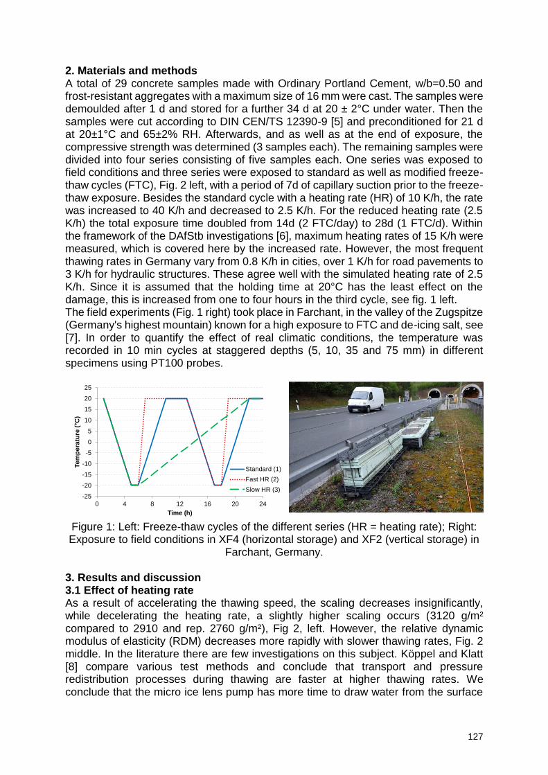
127
2. Materials and methods A total of 29 concrete samples made with Ordinary Portland Cement, w/b=0.50 and frost-resistant aggregates with a maximum size of 16 mm were cast. The samples were demoulded after 1 d and stored for a further 34 d at 20 ± 2°C under water. Then the samples were cut according to DIN CEN/TS 12390-9 [5] and preconditioned for 21 d at 20±1°C and 65±2% RH. Afterwards, and as well as at the end of exposure, the compressive strength was determined (3 samples each). The remaining samples were divided into four series consisting of five samples each. One series was exposed to field conditions and three series were exposed to standard as well as modified freeze-thaw cycles (FTC), Fig. 2 left, with a period of 7d of capillary suction prior to the freeze-thaw exposure. Besides the standard cycle with a heating rate (HR) of 10 K/h, the rate was increased to 40 K/h and decreased to 2.5 K/h. For the reduced heating rate (2.5 K/h) the total exposure time doubled from 14d (2 FTC/day) to 28d (1 FTC/d). Within the framework of the DAfStb investigations [6], maximum heating rates of 15 K/h were measured, which is covered here by the increased rate. However, the most frequent thawing rates in Germany vary from 0.8 K/h in cities, over 1 K/h for road pavements to 3 K/h for hydraulic structures. These agree well with the simulated heating rate of 2.5 K/h. Since it is assumed that the holding time at 20°C has the least effect on the damage, this is increased from one to four hours in the third cycle, see fig. 1 left. The field experiments (Fig. 1 right) took place in Farchant, in the valley of the Zugspitze (Germany's highest mountain) known for a high exposure to FTC and de-icing salt, see [7]. In order to quantify the effect of real climatic conditions, the temperature was recorded in 10 min cycles at staggered depths (5, 10, 35 and 75 mm) in different specimens using PT100 probes.
Figure 1: Left: Freeze-thaw cycles of the different series (HR = heating rate); Right: Exposure to field conditions in XF4 (horizontal storage) and XF2 (vertical storage) in
Farchant, Germany. 3. Results and discussion 3.1 Effect of heating rate As a result of accelerating the thawing speed, the scaling decreases insignificantly, while decelerating the heating rate, a slightly higher scaling occurs (3120 g/m² compared to 2910 and rep. 2760 g/m²), Fig 2, left. However, the relative dynamic modulus of elasticity (RDM) decreases more rapidly with slower thawing rates, Fig. 2 middle. In the literature there are few investigations on this subject. Köppel and Klatt [8] compare various test methods and conclude that transport and pressure redistribution processes during thawing are faster at higher thawing rates. We conclude that the micro ice lens pump has more time to draw water from the surface
-25
-20
-15
-10
-5
0
5
10
15
20
25
0 4 8 12 16 20 24
Te
mp
era
ture
( C
)
Time (h)
Standard (1)
Fast HR (2)
Slow HR (3)
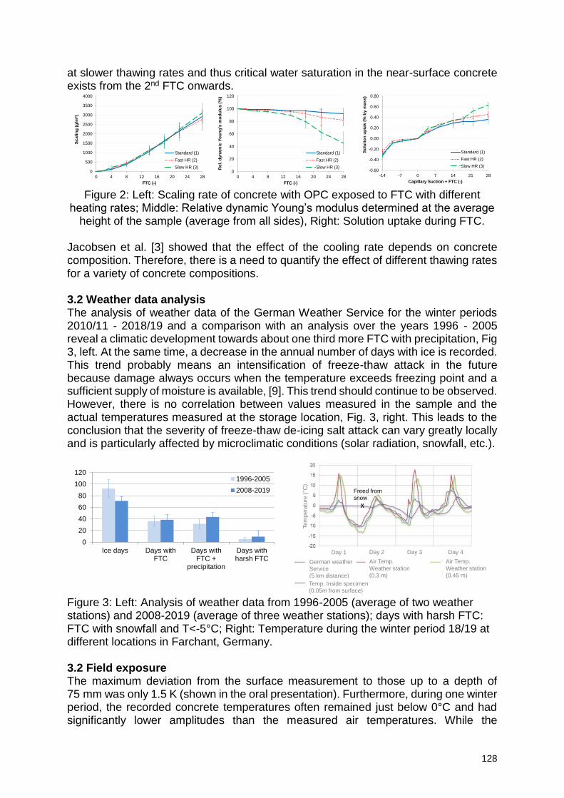
128
at slower thawing rates and thus critical water saturation in the near-surface concrete exists from the 2nd FTC onwards.
Figure 2: Left: Scaling rate of concrete with OPC exposed to FTC with different
heating rates; Middle: Relative dynamic Young’s modulus determined at the average height of the sample (average from all sides), Right: Solution uptake during FTC.
Jacobsen et al. [3] showed that the effect of the cooling rate depends on concrete composition. Therefore, there is a need to quantify the effect of different thawing rates for a variety of concrete compositions. 3.2 Weather data analysis The analysis of weather data of the German Weather Service for the winter periods 2010/11 - 2018/19 and a comparison with an analysis over the years 1996 - 2005 reveal a climatic development towards about one third more FTC with precipitation, Fig 3, left. At the same time, a decrease in the annual number of days with ice is recorded. This trend probably means an intensification of freeze-thaw attack in the future because damage always occurs when the temperature exceeds freezing point and a sufficient supply of moisture is available, [9]. This trend should continue to be observed. However, there is no correlation between values measured in the sample and the actual temperatures measured at the storage location, Fig. 3, right. This leads to the conclusion that the severity of freeze-thaw de-icing salt attack can vary greatly locally and is particularly affected by microclimatic conditions (solar radiation, snowfall, etc.).
Figure 3: Left: Analysis of weather data from 1996-2005 (average of two weather stations) and 2008-2019 (average of three weather stations); days with harsh FTC: FTC with snowfall and T<-5°C; Right: Temperature during the winter period 18/19 at different locations in Farchant, Germany. 3.2 Field exposure The maximum deviation from the surface measurement to those up to a depth of 75 mm was only 1.5 K (shown in the oral presentation). Furthermore, during one winter period, the recorded concrete temperatures often remained just below 0°C and had significantly lower amplitudes than the measured air temperatures. While the
0
500
1000
1500
2000
2500
3000
3500
4000
0 4 8 12 16 20 24 28
Sc
ali
ng
(g
/m²)
FTC (-)
Standard (1)
Fast HR (2)
Slow HR (3)0
20
40
60
80
100
120
0 4 8 12 16 20 24 28
Re
l. d
yn
am
ic Y
ou
ng
's m
od
ulu
s (
%)
FTC (-)
Standard (1)
Fast HR (2)
Slow HR (3)-0.60
-0.40
-0.20
0.00
0.20
0.40
0.60
0.80
-14 -7 0 7 14 21 28
So
luti
on
up
tak
(%
by m
as
s)
Capillary Suction + FTC (-)
Standard (1)
Fast HR (2)
Slow HR (3)
0
20
40
60
80
100
120
Ice days Days withFTC
Days withFTC +
precipitation
Days withharsh FTC
1996-2005
2008-2019
Te
mp
era
ture
(°C
)
Day 1 Day 2 Day 3 Day 4
German weather
Service
(5 km distance)
Air Temp.
Weather station
(0.3 m)
Air Temp.
Weather station
(0.45 m)
Temp. Inside specimen
(0.05m from surface)
x
Freed from
snow
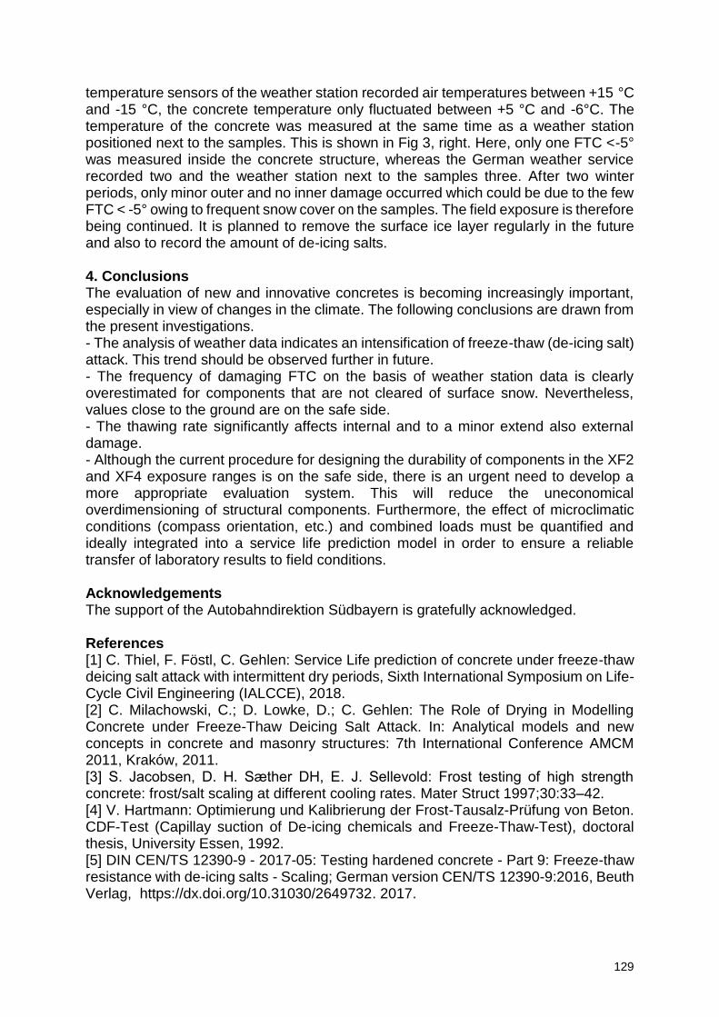
129
temperature sensors of the weather station recorded air temperatures between +15 °C and -15 °C, the concrete temperature only fluctuated between +5 °C and -6°C. The temperature of the concrete was measured at the same time as a weather station positioned next to the samples. This is shown in Fig 3, right. Here, only one FTC <-5° was measured inside the concrete structure, whereas the German weather service recorded two and the weather station next to the samples three. After two winter periods, only minor outer and no inner damage occurred which could be due to the few FTC < -5° owing to frequent snow cover on the samples. The field exposure is therefore being continued. It is planned to remove the surface ice layer regularly in the future and also to record the amount of de-icing salts. 4. Conclusions The evaluation of new and innovative concretes is becoming increasingly important, especially in view of changes in the climate. The following conclusions are drawn from the present investigations. - The analysis of weather data indicates an intensification of freeze-thaw (de-icing salt) attack. This trend should be observed further in future. - The frequency of damaging FTC on the basis of weather station data is clearly overestimated for components that are not cleared of surface snow. Nevertheless, values close to the ground are on the safe side. - The thawing rate significantly affects internal and to a minor extend also external damage. - Although the current procedure for designing the durability of components in the XF2 and XF4 exposure ranges is on the safe side, there is an urgent need to develop a more appropriate evaluation system. This will reduce the uneconomical overdimensioning of structural components. Furthermore, the effect of microclimatic conditions (compass orientation, etc.) and combined loads must be quantified and ideally integrated into a service life prediction model in order to ensure a reliable transfer of laboratory results to field conditions. Acknowledgements The support of the Autobahndirektion Südbayern is gratefully acknowledged. References [1] C. Thiel, F. Föstl, C. Gehlen: Service Life prediction of concrete under freeze-thaw deicing salt attack with intermittent dry periods, Sixth International Symposium on Life-Cycle Civil Engineering (IALCCE), 2018. [2] C. Milachowski, C.; D. Lowke, D.; C. Gehlen: The Role of Drying in Modelling Concrete under Freeze-Thaw Deicing Salt Attack. In: Analytical models and new concepts in concrete and masonry structures: 7th International Conference AMCM 2011, Kraków, 2011. [3] S. Jacobsen, D. H. Sӕther DH, E. J. Sellevold: Frost testing of high strength concrete: frost/salt scaling at different cooling rates. Mater Struct 1997;30:33–42. [4] V. Hartmann: Optimierung und Kalibrierung der Frost-Tausalz-Prüfung von Beton. CDF-Test (Capillay suction of De-icing chemicals and Freeze-Thaw-Test), doctoral thesis, University Essen, 1992. [5] DIN CEN/TS 12390-9 - 2017-05: Testing hardened concrete - Part 9: Freeze-thaw resistance with de-icing salts - Scaling; German version CEN/TS 12390-9:2016, Beuth Verlag, https://dx.doi.org/10.31030/2649732. 2017.
130
[6] H.S. Müller, U. Guse, U.: Zusammenfassender Bericht zum Verbundforschungs-vorhaben "Übertragbarkeit von Frost-Laborprüfungen auf Praxisverhältnisse". DAfStb Heft 577 (2010). [7] C. Brandes; P. Schießl, P.: Alterungseinfluss auf den Frost-Tausalz-Widerstand von Beton. Wissenschaftlicher Kurzbericht Nr. 1, Technical University of Munich, 2005. [8] F. Köppel, W. Klatt: Gegenüberstellung von Prüfverfahren zur Bestimmung der Frost- und Frost-Tausalz-Beständigkeit von Normalbetonen unterschiedlicher Zusammensetzung. Bachelor Thesis, OTH Regensburg, 2014. [9] Y. Djuric: Sättigungsverhalten und Schädigung von Zementstein bei Frostbeanspruchung, doctoral thesis, KIT, Karlsruhe, 2018.
131
Taking into account climatic data in the modelling of the thermal behaviour of concrete under freeze-thaw cycles
S. Al Haj Sleiman1,2, F. Grondin1, L. Izoret2
1 Institut de Recherche en Génie Civil et Mécanique (GeM), UMR 6183, Centrale Nantes – Université de Nantes – CNRS, 1 Rue de la Noë, 44321 Nantes, France – emails [email protected]; [email protected] 2 Association Technique de l’Industrie des Liants Hydrauliques(ATILH), 7, place de la Défense 92974 Paris-la-Défense Cedex, France - email [email protected]
Abstract This paper presents a numerical model to simulate the thermal behaviour of concrete blocks exposed to freeze-thaw cycles including the solar contribution on the surface and using real climatic data as input. The treated problem is a transient thermal problem. Experimental data were measured on concrete blocks in a region located in a severe frost area in France. The results show a good comparison between simulations and measurements of temperature in the concrete blocks. The main goal of this work was to calibrate a thermal model considering the solar radiation for concrete at low temperatures. The next objective will consider a coupling with a mechanical model to calculate the deformation and damage due to thermal dilatation, pore pressure, ice formation, etc. Keywords: thermal modelling, freeze-thaw cycles, concrete, severe frost zone.
1. Introduction In the context of ensuring the durability of concrete structures exposed to the effects of freezing and thawing, the material must have adequate resistance to this action. Many test methods have been developed, such as the Slab test [1], the French tests such as NF P 18-420 [2], CIF test [3], ASTM standard test method for resistance of concrete to rapid freezing and thawing [4]. Nevertheless, these tests do not apply temperatures from the climatic data to which concrete is exposed but conventional thermal cycles over 12 or 24 hours and with a common range of +20/-20°C. Questions arise as to the representativeness of these tests and their correlations to real exposure conditions. In our research project, measurements were carried out at Mont Aigoual, a French mountainous region located in an area classified as a “severe frost zone” (according to the exposure classes of the NF EN 206-1) [5]. Measurements were made on concrete blocks equipped with thermocouples placed at 2 cm from the surface and connected to a data recording and storage device. These experimental measurements were also used as input data for a numerical model. The main idea is to model the thermal behaviour of concrete exposed to real freeze-thaw cycles and to provide a code that can be used to predict the thermal deformations of cementitious material exposed to thermal cycles, while taking into account the effect of solar radiation and real exposure conditions. 2. Problem formulation A concrete body is considered to be subjected to different thermal phenomena, as shown in the figure 1.
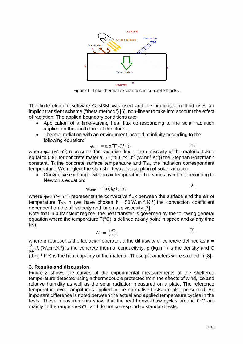
132
Figure 1: Total thermal exchanges in concrete blocks.
The finite element software Cast3M was used and the numerical method uses an implicit transient scheme ("theta method") [6], non-linear to take into account the effect of radiation. The applied boundary conditions are:
Application of a time-varying heat flux corresponding to the solar radiation applied on the south face of the block.
Thermal radiation with an environment located at infinity according to the following equation:
φirr = ε. σ(Ts4-Tciel
4 ) ; (1)
where φirr (W.m-2) represents the radiative flux, ε the emissivity of the material taken
equal to 0.95 for concrete material, σ (=5.67x10⁻⁸ (W.m-2.K-4)) the Stephan Boltzmann constant, Ts the concrete surface temperature and Tsky the radiation correspondent temperature. We neglect the slab short-wave absorption of solar radiation.
Convective exchange with an air temperature that varies over time according to Newton’s equation:
φconv = h (Ts-Tair) ; (2)
where φcon (W.m-2) represents the convective flux between the surface and the air of
temperature Tair, h (we have chosen h = 50 W. m-2. K-1) the convection coefficient dependent on the air velocity and kinematic viscosity [7]. Note that in a transient regime, the heat transfer is governed by the following general equation where the temperature T(°C) is defined at any point in space and at any time t(s):
∆T = 1
a
∂T
∂t ;
(3)
where ∆ represents the laplacian operator, a the diffusivity of concrete defined as a =λ
ρ.C. λ (W.m-1.K-1) is the concrete thermal conductivity, ρ (kg.m-3) is the density and C
(J.kg-1.K-1) is the heat capacity of the material. These parameters were studied in [8]. 3. Results and discussion Figure 2 shows the curves of the experimental measurements of the sheltered temperature detected using a thermocouple protected from the effects of wind, ice and relative humidity as well as the solar radiation measured on a plate. The reference temperature cycle amplitudes applied in the normative tests are also presented. An important difference is noted between the actual and applied temperature cycles in the tests. These measurements show that the real freeze-thaw cycles around 0°C are mainly in the range -5/+5°C and do not correspond to standard tests.
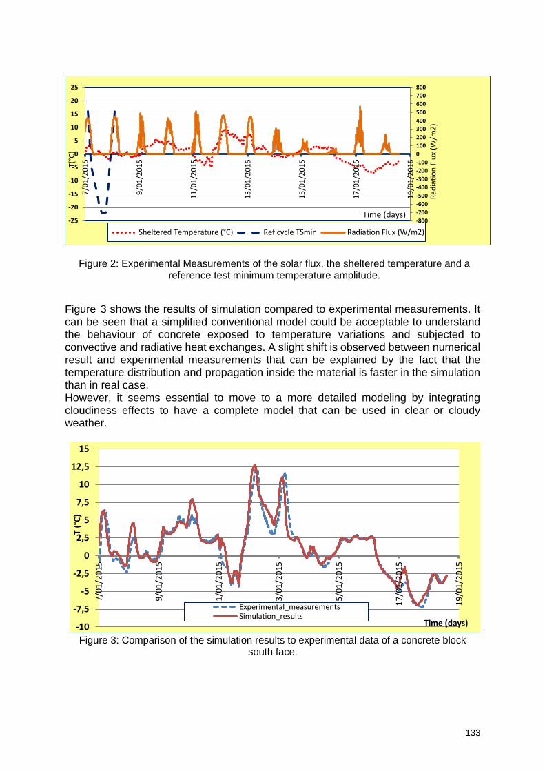
133
Figure 2: Experimental Measurements of the solar flux, the sheltered temperature and a reference test minimum temperature amplitude.
Figure 3 shows the results of simulation compared to experimental measurements. It can be seen that a simplified conventional model could be acceptable to understand the behaviour of concrete exposed to temperature variations and subjected to convective and radiative heat exchanges. A slight shift is observed between numerical result and experimental measurements that can be explained by the fact that the temperature distribution and propagation inside the material is faster in the simulation than in real case. However, it seems essential to move to a more detailed modeling by integrating cloudiness effects to have a complete model that can be used in clear or cloudy weather.
Figure 3: Comparison of the simulation results to experimental data of a concrete block
south face.
-800
-700
-600
-500
-400
-300
-200
-100
0
100
200
300
400
500
600
700
800
-25
-20
-15
-10
-5
0
5
10
15
20
257
/01
/20
15
9/0
1/2
01
5
11
/01
/20
15
13
/01
/20
15
15
/01
/20
15
17
/01
/20
15
19
/01
/20
15
Rad
iati
on
Flu
x (W
/m2
)
T(°C
)
Time (days)
Sheltered Temperature (°C) Ref cycle TSmin Radiation Flux (W/m2)
-10
-7,5
-5
-2,5
0
2,5
5
7,5
10
12,5
15
7/0
1/2
01
5
9/0
1/2
01
5
11
/01
/20
15
13
/01
/20
15
15
/01
/20
15
17
/01
/20
15
19
/01
/20
15
T (°
C)
Time (days)
Experimental_measurementsSimulation_results
134
4. Conclusion This work proposed a simplified transient thermal model that will likely be used to predict the temperature distribution on the surface of a concrete body or even in its body subjected to temperature variations in a severe freezing zone while including the effect of solar radiation and actual exposure conditions. The measurements on concrete blocks at the Mont Aigoual showed that the main freeze-thaw cycles in 24h were in the range -5/+5°C. Other cycles can be observed at negative temperatures or positive temperatures. It leads to say that we have three types of cycles: negative-negative temperatures cycles, negative-positive temperatures cycles, positive-positive temperatures cycles. Initial results show that simplified modelling could be used to understand concrete behaviour and predict temperature variations near the surface or in the body of the structure under study. The prospects of this model are to move to a complete model including the effects of cloudiness as well as to take into account the diffused part of solar radiation that will be absorbed by clouds and atmosphere. A work is in course to couple this model to a mechanical approach to model concrete damage under freeze and thaw actions. References [1] M. Science, “RILEM TECHNICAL COMMITTEES Slab Test - Freeze / Thaw Resistance of Concrete – Internal deterioration,” vol. 34, no. November 2001, pp. 526–531, 2002. [2] AFNOR, “NF XP P18-420 AFNOR Béton : Essai d’écaillage des surfaces de béton durci exposées au gel en présence d’une solution saline.” [3] P. M. J. Setzer, “CIF-Test - Capillary suction , Internal damage and Freeze thaw Test Reference method and alternative methods A and B,” vol. 34, no. November 2001, pp. 515–525, 2002. [4] R. Freezing, C. Concrete, and B. Statements, “Standard Test Method for Resistance of Concrete to Rapid Freezing and Thawing 1,” vol. 03, no. Reapproved, pp. 1–6, 2008. [5] AFNOR, “NF EN 206-1/CN.” [6] R. Generales, A. Theorique, R. Biographiques, and T. D. E. S. Structures, “Calculs thermiques.” [7] Jiji LM, Heat Convection, 2 ed. Berl. 2009. [8] Y. Qin and J. E. Hiller, “Modeling temperature distribution in rigid pavement slabs: Impact of air temperature,” Constr. Build. Mater., vol. 25, no. 9, pp. 3753–3761, 2011.
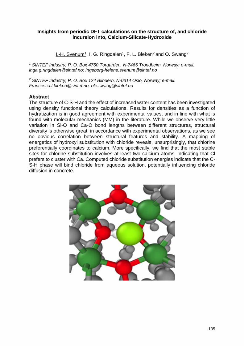
135
Insights from periodic DFT calculations on the structure of, and chloride incursion into, Calcium-Silicate-Hydroxide
I.-H. Svenum1, I. G. Ringdalen1, F. L. Bleken2 and O. Swang2 1 SINTEF Industry, P. O. Box 4760 Torgarden, N-7465 Trondheim, Norway; e-mail: [email protected]; [email protected] 2 SINTEF Industry, P. O. Box 124 Blindern, N-0314 Oslo, Norway; e-mail: [email protected]; [email protected]
Abstract The structure of C-S-H and the effect of increased water content has been investigated using density functional theory calculations. Results for densities as a function of hydratization is in good agreement with experimental values, and in line with what is found with molecular mechanics (MM) in the literature. While we observe very little variation in Si-O and Ca-O bond lengths between different structures, structural diversity is otherwise great, in accordance with experimental observations, as we see no obvious correlation between structural features and stability. A mapping of energetics of hydroxyl substitution with chloride reveals, unsurprisingly, that chlorine preferentially coordinates to calcium. More specifically, we find that the most stable sites for chlorine substitution involves at least two calcium atoms, indicating that Cl prefers to cluster with Ca. Computed chloride substitution energies indicate that the C-S-H phase will bind chloride from aqueous solution, potentially influencing chloride diffusion in concrete.
136
A performance-based design approach for durability design of concrete structures in acidic environments
J. Gerlach1, L. Lohaus1, M. Haist1
1 Institute of Building Materials Science, Leibniz University Hannover, Appelstraße 9A, 30167 Hannover, Germany – email: [email protected]; [email protected]; [email protected]
Abstract Due to limitations of the current prescriptive design approach for concrete durability, performance-based design concepts are increasingly gaining importance. Consequently, much effort has been spent in recent years and various approaches have been developed. These approaches primarily cover concrete degradation due to chloride ingress and carbonation. Similar approaches for acid attack are not available so far. In this context, this paper introduces a novel approach for durability design of concrete structures in acidic environments. By explicitly taking into account environmental loads and material resistance, this approach allows a quantitative consideration of durability. Keywords: acid attack, durability design, diffusion-erosion-model, performance testing, reliability-based design 1. Introduction The common design approach to ensure concrete durability is currently based on prescriptive specifications. Since this approach is based on experiences, a quantitative estimation of performance and/or service life is not possible. Thus, performance-based durability design is increasingly gaining importance. Compared to other degradation mechanism, such as chloride ingress or carbonation, the development of performance-based design approaches for acid attack has not progressed so far. In this context, a novel performance-based design concept for durability design of concrete structures in acidic environments was developed. This approach is presented in this paper. A key demand for performance-based design approaches are reliable and reproducible results. For this objective, Section 2 highlights fundamental testing principles. Considering acid attack on concrete structures, it must be kept in mind that reduced structural dimensions have to be assumed at the end of the service life due to the formation of a corroded surface layer with low mechanical strength. Consequently, the exclusive consideration of material resistance is not sufficient and the specification of a performance limit has to be in conjunction with required structural dimensions. Therefore, it becomes necessary to consider the degradation of the structural component. For this purpose, a newly developed diffusion-erosion-model is presented in Section 3. For the actual design of the structural components, a reliability-based limit state formulation is introduced in Section 4. Different levels of limit state design are considered by means of an illustrative example. 2. Performance Testing The various fields of application in which concrete structures are attacked by acidic solutions are also reflected in the broad spectrum of existing test methods. These methods differ considerably associated with a wide range of test parameters [1, 3]. The
137
inevitable consequence of this wide range of test parameters is that degradation mechanisms and kinetics can differ depending on the applied test method. Consequently, the resulting outcomes and findings may also differ and can even be contradictory. In order to overcome this drawback, it is essential to follow certain principles during testing. First, it is necessary that prevailing field conditions are reflected with sufficient accuracy. However, it must be noticed that one single test method cannot reflect all in-situ scenarios. Hence, performance testing requires a limitation to essential influencing parameters and boundary conditions. A key demand of performance testing is reliability and reproducibility. The fundamental requirement for reproducible test results is the generation of roughly comparable exposure conditions. Therefore, an independent exposure, regardless of the resistance, has to be generated. This aspect relates in particular to the aggressiveness of the attacking solution. Due to the ongoing reaction between acidic solution and exposed concrete, the acid concentration has to be kept constant or within defined limits. Furthermore, the level of saturation of dissolved ions has also to be taken into consideration. With an increasing level of saturation, the reactivity of the attacking acidic solution decreases and, hence, influences the corrosion process. Therefore, the test medium has to be renewed with regard to the acid-specific saturation concentrations of the formed salts. Besides the aggressiveness of the attacking solution, thermodynamic boundary conditions, in particular temperature, have to be addressed and kept within defined limits. Furthermore, the formation and chemical composition of the degraded surface zone as well as possible precipitation of secondary products (e.g. gypsum) have to be considered. If this degraded layer is partially or completely removed, degradation kinetics change. Moreover, potential influences of flow conditions and mixing have to be taken into consideration. In summary, it can be argued that for reliable and reproducible test results different testing principles concerning prevailing exposure and boundary conditions have to be fulfilled. Besides a standardized procedure for manufacturing, preparation and curing of test specimens, these requirements relate especially to the following parameters:
Concentration of attacking solution
Saturation of attacking solution
Temperature of attacking solution
Mechanical action
Flow conditions & mixing
3. Degradation Modelling Concrete corrosion due to acid attack comprises a number of complex physical and chemical processes as well as their interactions. However, for the prediction of the time-dependent corrosion process two major mechanism can be identified, which greatly influence the corrosion kinetics. The first mechanism is the degradation of the cement paste matrix. On the one hand, this mechanism is influenced by the diffusive ion transport caused by the concentration gradient between the attacking acid and the highly alkaline cement paste. On the other hand, this mechanism is affected by the dissolution of the hydrated cement phases. Since the dissolution proceeds much faster than the diffusive transport, the overall process is governed by diffusion and can therefore be described by Fick’s laws of diffusion. The second mechanism is the erosion of the degraded surface. This mechanism is significantly determined by the stability of the corroded cement paste.
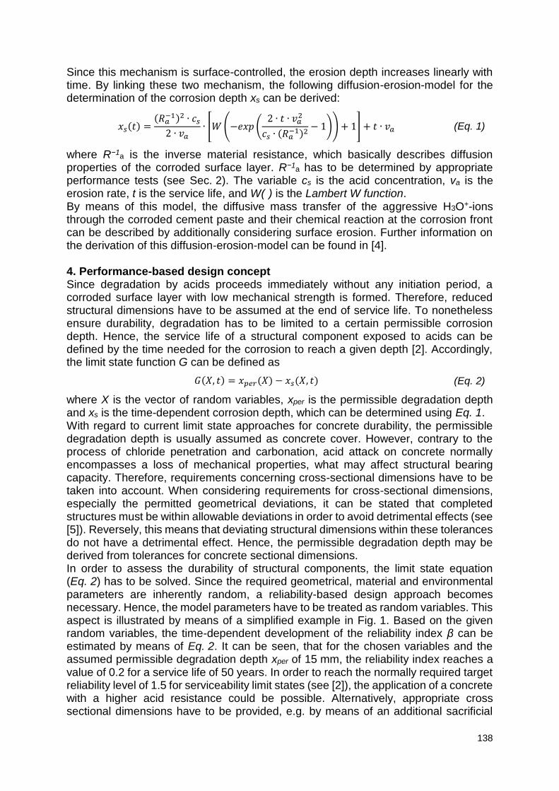
138
Since this mechanism is surface-controlled, the erosion depth increases linearly with time. By linking these two mechanism, the following diffusion-erosion-model for the determination of the corrosion depth xs can be derived:
𝑥𝑠(𝑡) =(𝑅𝑎
−1)2 ∙ 𝑐𝑠
2 ∙ 𝑣𝑎∙ [𝑊 (−𝑒𝑥𝑝 (
2 ∙ 𝑡 ∙ 𝑣𝑎2
𝑐𝑠 ∙ (𝑅𝑎−1)2
− 1)) + 1] + 𝑡 ∙ 𝑣𝑎 (Eq. 1)
where R−1a is the inverse material resistance, which basically describes diffusion
properties of the corroded surface layer. R−1a has to be determined by appropriate
performance tests (see Sec. 2). The variable cs is the acid concentration, va is the erosion rate, t is the service life, and W(·) is the Lambert W function. By means of this model, the diffusive mass transfer of the aggressive H3O+-ions through the corroded cement paste and their chemical reaction at the corrosion front can be described by additionally considering surface erosion. Further information on the derivation of this diffusion-erosion-model can be found in [4]. 4. Performance-based design concept Since degradation by acids proceeds immediately without any initiation period, a corroded surface layer with low mechanical strength is formed. Therefore, reduced structural dimensions have to be assumed at the end of service life. To nonetheless ensure durability, degradation has to be limited to a certain permissible corrosion depth. Hence, the service life of a structural component exposed to acids can be defined by the time needed for the corrosion to reach a given depth [2]. Accordingly, the limit state function G can be defined as
𝐺(𝑋, 𝑡) = 𝑥𝑝𝑒𝑟(𝑋) − 𝑥𝑠(𝑋, 𝑡) (Eq. 2)
where X is the vector of random variables, xper is the permissible degradation depth and xs is the time-dependent corrosion depth, which can be determined using Eq. 1. With regard to current limit state approaches for concrete durability, the permissible degradation depth is usually assumed as concrete cover. However, contrary to the process of chloride penetration and carbonation, acid attack on concrete normally encompasses a loss of mechanical properties, what may affect structural bearing capacity. Therefore, requirements concerning cross-sectional dimensions have to be taken into account. When considering requirements for cross-sectional dimensions, especially the permitted geometrical deviations, it can be stated that completed structures must be within allowable deviations in order to avoid detrimental effects (see [5]). Reversely, this means that deviating structural dimensions within these tolerances do not have a detrimental effect. Hence, the permissible degradation depth may be derived from tolerances for concrete sectional dimensions. In order to assess the durability of structural components, the limit state equation (Eq. 2) has to be solved. Since the required geometrical, material and environmental parameters are inherently random, a reliability-based design approach becomes necessary. Hence, the model parameters have to be treated as random variables. This aspect is illustrated by means of a simplified example in Fig. 1. Based on the given random variables, the time-dependent development of the reliability index β can be estimated by means of Eq. 2. It can be seen, that for the chosen variables and the assumed permissible degradation depth xper of 15 mm, the reliability index reaches a value of 0.2 for a service life of 50 years. In order to reach the normally required target reliability level of 1.5 for serviceability limit states (see [2]), the application of a concrete with a higher acid resistance could be possible. Alternatively, appropriate cross sectional dimensions have to be provided, e.g. by means of an additional sacrificial
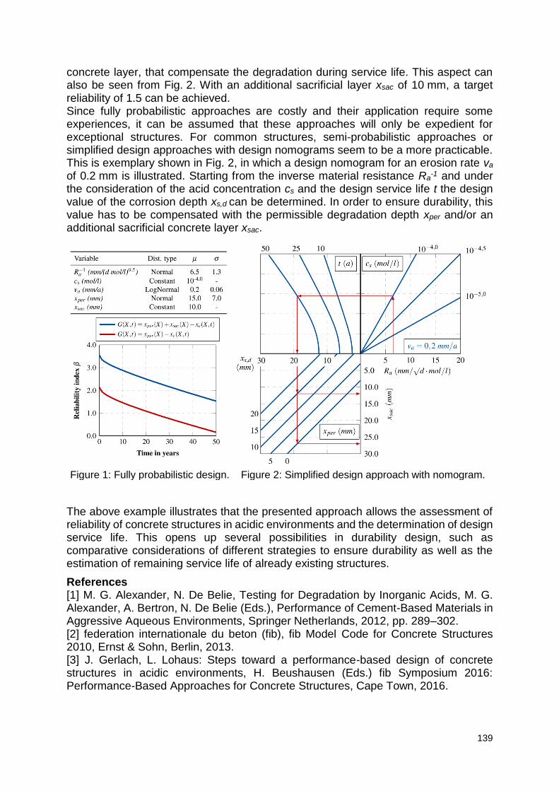
139
concrete layer, that compensate the degradation during service life. This aspect can also be seen from Fig. 2. With an additional sacrificial layer xsac of 10 mm, a target reliability of 1.5 can be achieved. Since fully probabilistic approaches are costly and their application require some experiences, it can be assumed that these approaches will only be expedient for exceptional structures. For common structures, semi-probabilistic approaches or simplified design approaches with design nomograms seem to be a more practicable. This is exemplary shown in Fig. 2, in which a design nomogram for an erosion rate va of 0.2 mm is illustrated. Starting from the inverse material resistance Ra
-1 and under the consideration of the acid concentration cs and the design service life t the design value of the corrosion depth xs,d can be determined. In order to ensure durability, this value has to be compensated with the permissible degradation depth xper and/or an additional sacrificial concrete layer xsac.
Figure 1: Fully probabilistic design. Figure 2: Simplified design approach with nomogram.
The above example illustrates that the presented approach allows the assessment of reliability of concrete structures in acidic environments and the determination of design service life. This opens up several possibilities in durability design, such as comparative considerations of different strategies to ensure durability as well as the estimation of remaining service life of already existing structures.
References [1] M. G. Alexander, N. De Belie, Testing for Degradation by Inorganic Acids, M. G. Alexander, A. Bertron, N. De Belie (Eds.), Performance of Cement-Based Materials in Aggressive Aqueous Environments, Springer Netherlands, 2012, pp. 289–302. [2] federation internationale du beton (fib), fib Model Code for Concrete Structures 2010, Ernst & Sohn, Berlin, 2013. [3] J. Gerlach, L. Lohaus: Steps toward a performance-based design of concrete structures in acidic environments, H. Beushausen (Eds.) fib Symposium 2016: Performance-Based Approaches for Concrete Structures, Cape Town, 2016.
140
[4] J. Gerlach, Ein performance-basiertes Konzept zur Dauerhaftigkeitsbemessung chemisch beanspruchter Betonbauteile, Institut für Baustoffe, Leibniz Universität Hannover, 2017, https://doi.org/10.15488/2711. [5] EN 13760:2009, Execution of concrete structures.
Session 4 Durability of infrastructure in the
energy sector; durability and sustainability of tailor-made
concrete in extreme conditions
142
Durability of concrete infrastructure and the role of smart self-
responsiveness admixtures
Jose Vera Agullo1
1ACCIONA Infrastructure S.A., Centro Tecnológico ACCIONA Infraestructuras. Valportillo Segunda nº8. 28108 Alcobendas, Madrid, SPAIN; e-mail: [email protected]
Abstract
ACCIONA Construction S.A., a Spanish contractor, is deeply interested in offering to
its clients long service life-spans for the infrastructure delivered. There is a clear
tendency in the sector of clients asking for longer life spans than ever, up to 120 years
in critical structures like bridges. This tendency is pushing the civil engineering
technology to search for innovative and reliable solutions. One part of this effort is
focused on the material science and technology, and more specifically in the
development of self-responsiveness admixtures to be used in concrete.
In this work, a summary of the approach of the LORCENIS project is given, showing
the demonstrators built in different harsh scenarios: North sea, mechanical fatigue,
thermal fatigue and acid attack.
143
Safety and sustainability of new admixtures for durable concrete
N. Al-Ayish 1, U. Mueller1, E.K. Karaxi2, I.Α. Kartsonakis2, C.Α. Charitidis2, L. De Meyst3
1RISE Research Institutes of Sweden, Drottning Kristinas väg 26, 114 28 Stockholm, Sweden email: [email protected]; [email protected] 2NTUA National Technical University of Athens, Research Unit of Advanced, Composite, Nanomaterials and Nanotechnology, Heroon Polytechniou St. 9, Zographos, Athens, Greece – email: [email protected]; [email protected]; [email protected] 3 Magnel Laboratory for Concrete Research, Ghent University, Tech Lane Ghent Science park, Campus A, Technologiepark-Zwijnaarde 60, 9052 Ghent, Belgium – email: : [email protected]
Abstract The sustainability of concrete infrastructures is highly dependent on the durability. A longer service life with low repair work reduces the resource use and hence the greenhouse gas emissions. New admixtures based on nanomaterials have the possibility to increase the service life. However, it is also important to consider the embodied impact of the material and safety issues concerning new nanomaterials. Here we present an overview on the latest developments on the safety and sustainability of some novel admixtures.
Keywords: Sustainability, concrete, admixtures, nanomaterials, safety 1. Introduction As the global population is growing there will be an increased need in energy demand. In order to have a safe and sustainable energy production, the infrastructure needs to be durable. Usually, the concrete is subjected to severe environments, e.g. high temperatures and seawater exposure, and there is an increased demand to extend the service life beyond what is prescribed in the design codes. Within the frame of the LORCENIS project, the goal is to develop long lasting reinforced concrete for energy infrastructures by involving customized protection, repairing and self-diagnosis methodologies through the use of novel, nanomaterial-based, admixtures. The environmental sustainability potential of concrete structures may be increased by 1) reducing Portland cement clinker content in the binder by e.g. using supplementary cementitious materials or admixtures; 2) optimizing the performance of the structure in relation to the material amount (cross-section); or 3) by increasing the service life and thus reducing waste and resource use from repair and maintenance. New admixtures based on nanomaterials have the possibility to increase the service life of concrete structures, especially since only a small amount is needed in order to increase the performance. However, it is also important to consider the embodied impact and safety issues concerning new nanomaterials. This paper presents a methodology of the sustainability potential and a preliminary life cycle assessment (LCA) of nano-incorporated additives for concrete infrastructures. 2. Sustainability approach There have been several studies of LCA of nanomaterials [1, 2]. Miseljic and Olsen [2] pointed out the necessity of including the performance of the nanomaterials in LCA
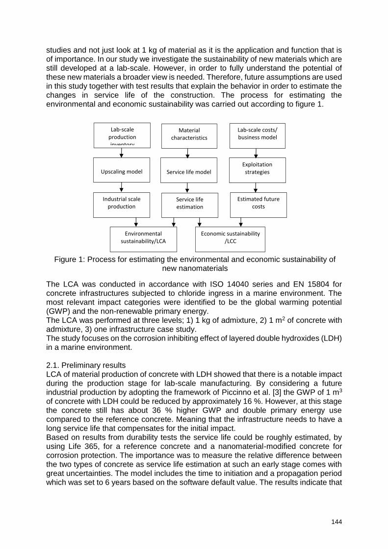
144
studies and not just look at 1 kg of material as it is the application and function that is of importance. In our study we investigate the sustainability of new materials which are still developed at a lab-scale. However, in order to fully understand the potential of these new materials a broader view is needed. Therefore, future assumptions are used in this study together with test results that explain the behavior in order to estimate the changes in service life of the construction. The process for estimating the environmental and economic sustainability was carried out according to figure 1. The LCA was conducted in accordance with ISO 14040 series and EN 15804 for concrete infrastructures subjected to chloride ingress in a marine environment. The most relevant impact categories were identified to be the global warming potential (GWP) and the non-renewable primary energy. The LCA was performed at three levels; 1) 1 kg of admixture, 2) 1 m2 of concrete with admixture, 3) one infrastructure case study. The study focuses on the corrosion inhibiting effect of layered double hydroxides (LDH) in a marine environment. 2.1. Preliminary results LCA of material production of concrete with LDH showed that there is a notable impact during the production stage for lab-scale manufacturing. By considering a future industrial production by adopting the framework of Piccinno et al. [3] the GWP of 1 m3 of concrete with LDH could be reduced by approximately 16 %. However, at this stage the concrete still has about 36 % higher GWP and double primary energy use compared to the reference concrete. Meaning that the infrastructure needs to have a long service life that compensates for the initial impact. Based on results from durability tests the service life could be roughly estimated, by using Life 365, for a reference concrete and a nanomaterial-modified concrete for corrosion protection. The importance was to measure the relative difference between the two types of concrete as service life estimation at such an early stage comes with great uncertainties. The model includes the time to initiation and a propagation period which was set to 6 years based on the software default value. The results indicate that
Environmental sustainability/LCA
Economic sustainability /LCC
Service life estimation
Industrial scale production
Estimated future costs
Upscaling model
Service life model
Exploitation strategies
Lab-scale production inventory
Material characteristics
Lab-scale costs/ business model
Figure 1: Process for estimating the environmental and economic sustainability of new nanomaterials
145
the service life could be extended by a factor of 3 using layered double hydroxides (LDH). The LCC analysis showed that although there is a higher investment cost for concrete with LDH, the future repair costs will be lower due to the occurrence later in time compared to higher repair costs in the near present of the reference concrete. 3. Health and safety When dealing with engineered nanomaterials and cementitious materials, it is also of importance to consider the health and safety aspects in the sustainability analysis as they are associated with risks for human health and the environment. The human exposure to some nanomaterials is associated with risk of e.g. lung diseases and skin irritations. The exposure potential is directly related to the nature, structure and form of the nanomaterial (e.g. free form, dispersed in a liquid, bound in a solid matrix). The exposure risk to particles in dry and free form is the highest in comparison to cases where nanomaterials are bounded in a matrix or dispersed in a liquid. One aim of the project is to make a risk assessment for added admixtures and give guidelines on how to minimize the risks in the product cycles including transfer of experiences by Safe-by-Design (SbD) principles. The aim is to ensure that risks are either prevented or adequately controlled. A decision tree for the selection of risk management measures related to nanomaterials in order to provide a quick selection of control measures was created in the frame of the LORCENIS project. Additionally, the risk assessment of the new admixtures with nanomaterials is ongoing in order to give guidance for material developers and to follow up the applied measures. Selected control banding tools, Stoffenmanager nanomodule [4] and Nanosafer [5] were utilized for risk assessment and management. Based on the assumption that inhalation is the most prominent risk during handling of the engineered nanomaterials in the innovation process, specific risk management measures for each nanoadditive were suggested according to the precautionary principle for the use of nanomaterials in an innovation project, in addition to the early stage development of the decision tree and along with the continuous monitoring of SbD principles implementation. 4. Discussion and conclusion A preliminary LCA and LCC were performed in order to estimate the sustainability potential of new nanomaterials for concrete energy infrastructures. The challenge in this study was to estimate the performance of the nanomaterials at a material development stage. The performance is key in order to include a life-cycle perspective which considers future effects of present decisions, for example an estimation of how the future production may look like. However, the question could also be turned the other way. Which performance do we need in order for the construction to be sustainable? What should we aim at in our research? Life cycle perspectives give indications on what the key influencing factors are which researchers material developers could focus on. In our case, the LCA is performed simultaneously and in an iterative way to pinpoint influencing production processes and to give indications on future applications. The preliminary results showed that the initial GWP and the non-renewable primary energy are significant but that the service life is indicated to compensate for that. It should, however, be noted that the durability tests are still ongoing and that the mechanism of LDH is not yet fully understood. In this stage, the reported results on
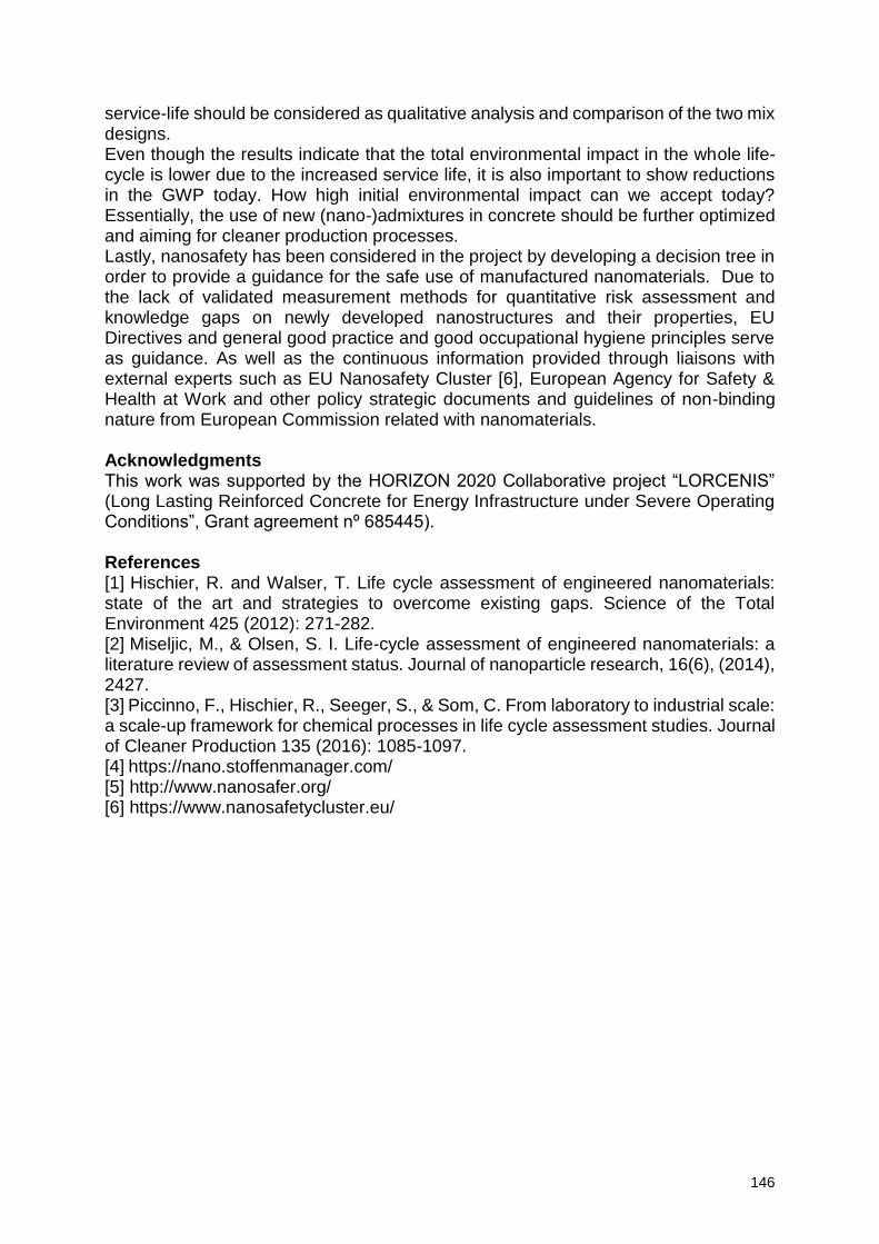
146
service-life should be considered as qualitative analysis and comparison of the two mix designs. Even though the results indicate that the total environmental impact in the whole life-cycle is lower due to the increased service life, it is also important to show reductions in the GWP today. How high initial environmental impact can we accept today? Essentially, the use of new (nano-)admixtures in concrete should be further optimized and aiming for cleaner production processes. Lastly, nanosafety has been considered in the project by developing a decision tree in order to provide a guidance for the safe use of manufactured nanomaterials. Due to the lack of validated measurement methods for quantitative risk assessment and knowledge gaps on newly developed nanostructures and their properties, EU Directives and general good practice and good occupational hygiene principles serve as guidance. As well as the continuous information provided through liaisons with external experts such as EU Nanosafety Cluster [6], European Agency for Safety & Health at Work and other policy strategic documents and guidelines of non-binding nature from European Commission related with nanomaterials. Acknowledgments This work was supported by the HORIZON 2020 Collaborative project “LORCENIS” (Long Lasting Reinforced Concrete for Energy Infrastructure under Severe Operating Conditions”, Grant agreement nº 685445). References [1] Hischier, R. and Walser, T. Life cycle assessment of engineered nanomaterials: state of the art and strategies to overcome existing gaps. Science of the Total Environment 425 (2012): 271-282. [2] Miseljic, M., & Olsen, S. I. Life-cycle assessment of engineered nanomaterials: a literature review of assessment status. Journal of nanoparticle research, 16(6), (2014), 2427. [3] Piccinno, F., Hischier, R., Seeger, S., & Som, C. From laboratory to industrial scale: a scale-up framework for chemical processes in life cycle assessment studies. Journal of Cleaner Production 135 (2016): 1085-1097. [4] https://nano.stoffenmanager.com/ [5] http://www.nanosafer.org/ [6] https://www.nanosafetycluster.eu/
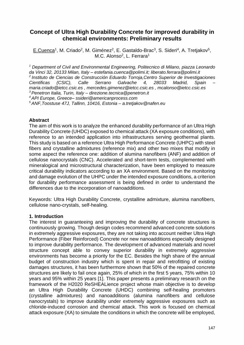
147
Concept of Ultra High Durability Concrete for improved durability in chemical environments: Preliminary results
E.Cuenca1, M. Criado2, M. Giménez2, E. Gastaldo-Brac3, S. Sideri4, A. Tretjakov5,
M.C. Alonso2, L. Ferrara1
1 Department of Civil and Environmental Engineering, Politecnico di Milano, piazza Leonardo da Vinci 32, 20133 Milan, Italy – [email protected]; [email protected] 2 Instituto de Ciencias de Construcción Eduardo Torroja,Centro Superior de Investigaciones Cientificas (CSIC), Calle Serrano Galvache 4, 28033 Madrid, Spain – [email protected] , [email protected] , [email protected] 3 Penetron Italia, Turin, Italy – [email protected] 4 API Europe, Greece– [email protected] 5 ANF,Toostuse 47J, Tallinn, 10416, Estonia – [email protected]
Abstract The aim of this work is to analyze the enhanced durability performance of an Ultra High Durability Concrete (UHDC) exposed to chemical attack (XA exposure conditions), with reference to an intended application into infrastructures serving geothermal plants. This study is based on a reference Ultra High Performance Concrete (UHPC) with steel fibers and crystalline admixtures (reference mix) and other two mixes that modify in some aspect the reference one: addition of alumina nanofibers (ANF) and addition of cellulose nanocrystals (CNC). Accelerated and short-term tests, complemented with mineralogical and microstructural characterization, have been employed to measure critical durability indicators according to an XA environment. Based on the monitoring and damage evolution of the UHPC under the intended exposure conditions, a criterion for durability performance assessment is being defined in order to understand the differences due to the incorporation of nanoadditions. Keywords: Ultra High Durability Concrete, crystalline admixture, alumina nanofibers, cellulose nano-crystals, self-healing. 1. Introduction The interest in guaranteeing and improving the durability of concrete structures is continuously growing. Though design codes recommend advanced concrete solutions in extremely aggressive exposures, they are not taking into account neither Ultra High Performance (Fiber Reinforced) Concrete nor new nanoadditions especially designed to improve durability performance. The development of advanced materials and novel structure concept able to convey superior durability in extremely aggressive environments has become a priority for the EC. Besides the high share of the annual budget of construction industry which is spent in repair and retrofitting of existing damages structures, it has been furthermore shown that 50% of the repaired concrete structures are likely to fail once again, 25% of which in the first 5 years, 75% within 10 years and 95% within 25 years [1]. This paper presents a preliminary research on the framework of the H2020 ReSHEALience project whose main objective is to develop an Ultra High Durability Concrete (UHDC) combining self-healing promoters (crystalline admixtures) and nanoadditions (alumina nanofibers and cellulose nanocrystals) to improve durability under extremely aggressive exposures such as chloride-induced corrosion and chemical attack. This work is focused on chemical attack exposure (XA) to simulate the conditions in which the concrete will be employed,
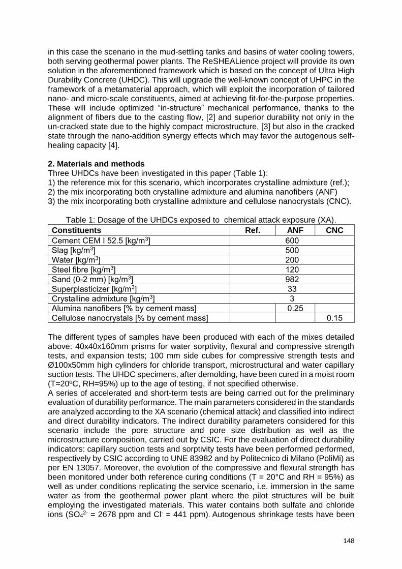
148
in this case the scenario in the mud-settling tanks and basins of water cooling towers, both serving geothermal power plants. The ReSHEALience project will provide its own solution in the aforementioned framework which is based on the concept of Ultra High Durability Concrete (UHDC). This will upgrade the well-known concept of UHPC in the framework of a metamaterial approach, which will exploit the incorporation of tailored nano- and micro-scale constituents, aimed at achieving fit-for-the-purpose properties. These will include optimized “in-structure” mechanical performance, thanks to the alignment of fibers due to the casting flow, [2] and superior durability not only in the un-cracked state due to the highly compact microstructure, [3] but also in the cracked state through the nano-addition synergy effects which may favor the autogenous self-healing capacity [4]. 2. Materials and methods Three UHDCs have been investigated in this paper (Table 1): 1) the reference mix for this scenario, which incorporates crystalline admixture (ref.); 2) the mix incorporating both crystalline admixture and alumina nanofibers (ANF) 3) the mix incorporating both crystalline admixture and cellulose nanocrystals (CNC).
Table 1: Dosage of the UHDCs exposed to chemical attack exposure (XA).
Constituents Ref. ANF CNC
Cement CEM I 52.5 [kg/m3] 600
Slag [kg/m3] 500
Water [kg/m3] 200
Steel fibre [kg/m3] 120
Sand (0-2 mm) [kg/m3] 982
Superplasticizer [kg/m3] 33
Crystalline admixture [kg/m3] 3
Alumina nanofibers [% by cement mass] 0.25
Cellulose nanocrystals [% by cement mass] 0.15
The different types of samples have been produced with each of the mixes detailed above: 40x40x160mm prisms for water sorptivity, flexural and compressive strength tests, and expansion tests; 100 mm side cubes for compressive strength tests and Ø100x50mm high cylinders for chloride transport, microstructural and water capillary suction tests. The UHDC specimens, after demolding, have been cured in a moist room (T=20ºC, RH=95%) up to the age of testing, if not specified otherwise. A series of accelerated and short-term tests are being carried out for the preliminary evaluation of durability performance. The main parameters considered in the standards are analyzed according to the XA scenario (chemical attack) and classified into indirect and direct durability indicators. The indirect durability parameters considered for this scenario include the pore structure and pore size distribution as well as the microstructure composition, carried out by CSIC. For the evaluation of direct durability indicators: capillary suction tests and sorptivity tests have been performed performed, respectively by CSIC according to UNE 83982 and by Politecnico di Milano (PoliMi) as per EN 13057. Moreover, the evolution of the compressive and flexural strength has been monitored under both reference curing conditions (T = 20°C and RH = 95%) as well as under conditions replicating the service scenario, i.e. immersion in the same water as from the geothermal power plant where the pilot structures will be built employing the investigated materials. This water contains both sulfate and chloride ions (SO4
2- = 2678 ppm and Cl- = 441 ppm). Autogenous shrinkage tests have been
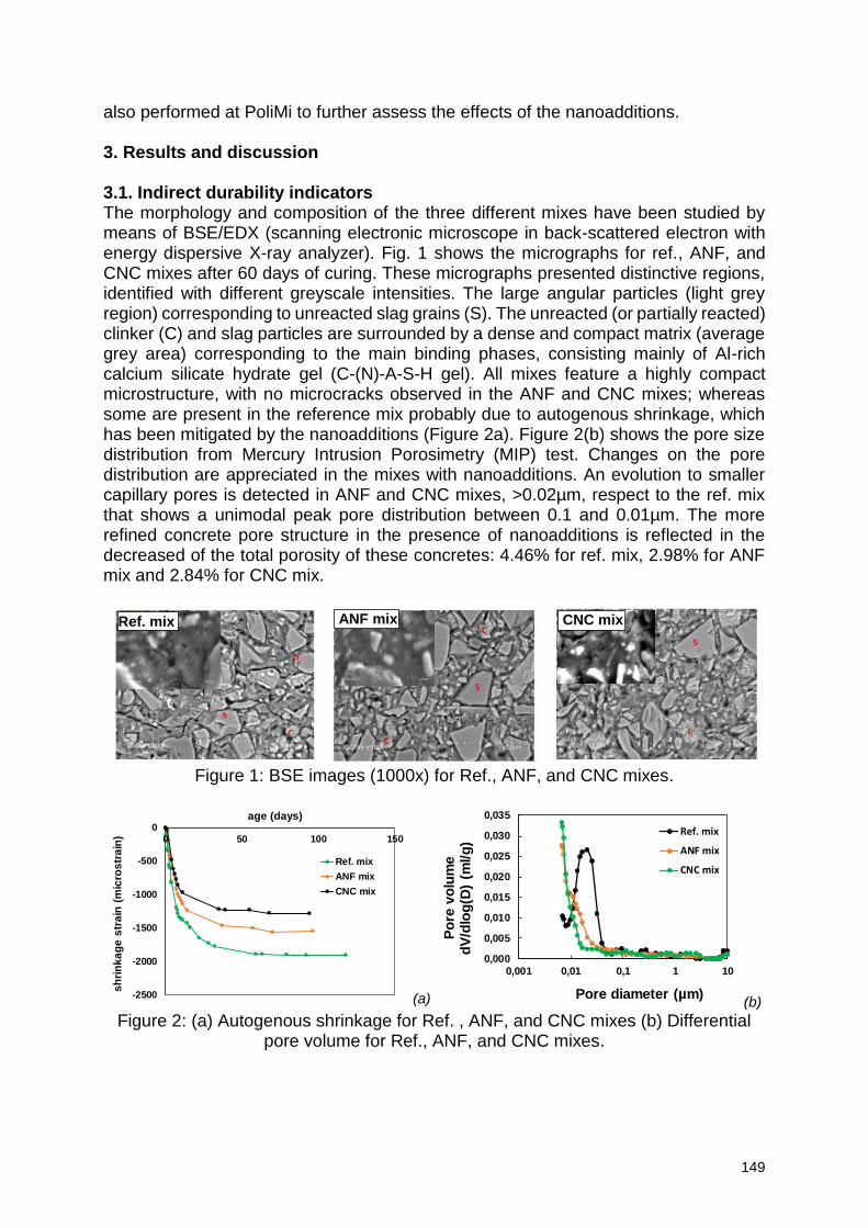
149
also performed at PoliMi to further assess the effects of the nanoadditions. 3. Results and discussion 3.1. Indirect durability indicators The morphology and composition of the three different mixes have been studied by means of BSE/EDX (scanning electronic microscope in back-scattered electron with energy dispersive X-ray analyzer). Fig. 1 shows the micrographs for ref., ANF, and CNC mixes after 60 days of curing. These micrographs presented distinctive regions, identified with different greyscale intensities. The large angular particles (light grey region) corresponding to unreacted slag grains (S). The unreacted (or partially reacted) clinker (C) and slag particles are surrounded by a dense and compact matrix (average grey area) corresponding to the main binding phases, consisting mainly of Al-rich calcium silicate hydrate gel (C-(N)-A-S-H gel). All mixes feature a highly compact microstructure, with no microcracks observed in the ANF and CNC mixes; whereas some are present in the reference mix probably due to autogenous shrinkage, which has been mitigated by the nanoadditions (Figure 2a). Figure 2(b) shows the pore size distribution from Mercury Intrusion Porosimetry (MIP) test. Changes on the pore distribution are appreciated in the mixes with nanoadditions. An evolution to smaller capillary pores is detected in ANF and CNC mixes, >0.02µm, respect to the ref. mix that shows a unimodal peak pore distribution between 0.1 and 0.01µm. The more refined concrete pore structure in the presence of nanoadditions is reflected in the decreased of the total porosity of these concretes: 4.46% for ref. mix, 2.98% for ANF mix and 2.84% for CNC mix.
Figure 1: BSE images (1000x) for Ref., ANF, and CNC mixes.
(a) (b)
Figure 2: (a) Autogenous shrinkage for Ref. , ANF, and CNC mixes (b) Differential pore volume for Ref., ANF, and CNC mixes.
-2500
-2000
-1500
-1000
-500
00 50 100 150
sh
rin
ka
ge
str
ain
(m
icro
str
ain
)
age (days)
Ref. mix
ANF mix
CNC mix
0,000
0,005
0,010
0,015
0,020
0,025
0,030
0,035
0,001 0,01 0,1 1 10
Po
re v
olu
me
dV
/dlo
g(D
) (m
l/g
)
Pore diameter (µm)
Ref. mix
ANF mix
CNC mix
Ref. mix ANF mix CNC mix
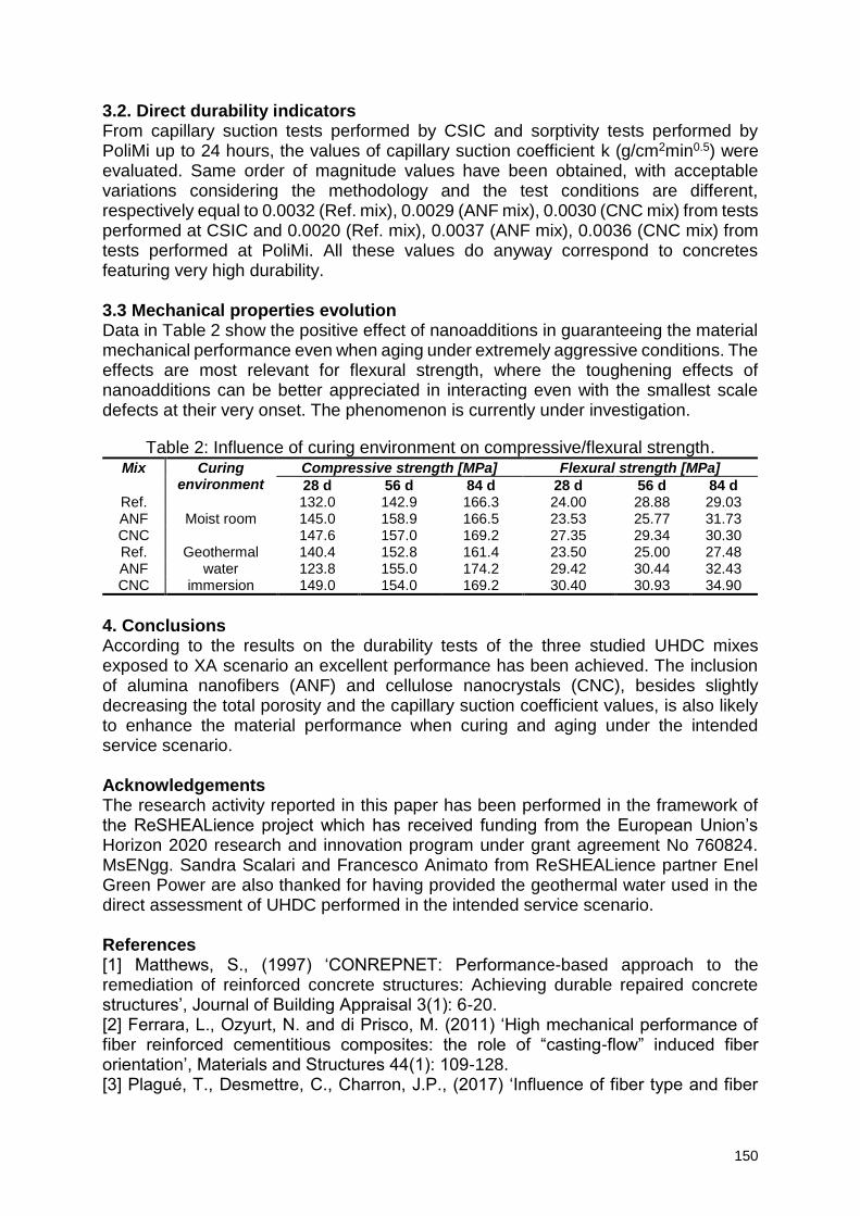
150
3.2. Direct durability indicators From capillary suction tests performed by CSIC and sorptivity tests performed by PoliMi up to 24 hours, the values of capillary suction coefficient k (g/cm2min0.5) were evaluated. Same order of magnitude values have been obtained, with acceptable variations considering the methodology and the test conditions are different, respectively equal to 0.0032 (Ref. mix), 0.0029 (ANF mix), 0.0030 (CNC mix) from tests performed at CSIC and 0.0020 (Ref. mix), 0.0037 (ANF mix), 0.0036 (CNC mix) from tests performed at PoliMi. All these values do anyway correspond to concretes featuring very high durability. 3.3 Mechanical properties evolution Data in Table 2 show the positive effect of nanoadditions in guaranteeing the material mechanical performance even when aging under extremely aggressive conditions. The effects are most relevant for flexural strength, where the toughening effects of nanoadditions can be better appreciated in interacting even with the smallest scale defects at their very onset. The phenomenon is currently under investigation.
Table 2: Influence of curing environment on compressive/flexural strength. Mix Curing
environment Compressive strength [MPa] Flexural strength [MPa]
28 d 56 d 84 d 28 d 56 d 84 d Ref.
Moist room 132.0 142.9 166.3 24.00 28.88 29.03
ANF 145.0 158.9 166.5 23.53 25.77 31.73 CNC 147.6 157.0 169.2 27.35 29.34 30.30 Ref. Geothermal
water immersion
140.4 152.8 161.4 23.50 25.00 27.48 ANF 123.8 155.0 174.2 29.42 30.44 32.43 CNC 149.0 154.0 169.2 30.40 30.93 34.90
4. Conclusions According to the results on the durability tests of the three studied UHDC mixes exposed to XA scenario an excellent performance has been achieved. The inclusion of alumina nanofibers (ANF) and cellulose nanocrystals (CNC), besides slightly decreasing the total porosity and the capillary suction coefficient values, is also likely to enhance the material performance when curing and aging under the intended service scenario. Acknowledgements The research activity reported in this paper has been performed in the framework of the ReSHEALience project which has received funding from the European Union’s Horizon 2020 research and innovation program under grant agreement No 760824. MsENgg. Sandra Scalari and Francesco Animato from ReSHEALience partner Enel Green Power are also thanked for having provided the geothermal water used in the direct assessment of UHDC performed in the intended service scenario. References [1] Matthews, S., (1997) ‘CONREPNET: Performance-based approach to the remediation of reinforced concrete structures: Achieving durable repaired concrete structures’, Journal of Building Appraisal 3(1): 6-20. [2] Ferrara, L., Ozyurt, N. and di Prisco, M. (2011) ‘High mechanical performance of fiber reinforced cementitious composites: the role of “casting-flow” induced fiber orientation’, Materials and Structures 44(1): 109-128. [3] Plagué, T., Desmettre, C., Charron, J.P., (2017) ‘Influence of fiber type and fiber
151
orientation on cracking and permeability of reinforced concrete under tensile loading’, Cement and Concrete Research, 94: 59-70. [4] Cuenca, E., Ferrara, L., (2017) ‘Self-healing capacity of fiber reinforced cementitious composites. State of the art and perspectives’, KSCE Journal of Civil Engineering 21(7): 2777-2789.
152
Ice abrasion resistance in high performance concrete engineered with smart admixtures
Arezou Babaahmadi1, Urs Mueller1, Kjell Tore Fossa2, Gunnar Moen2
1 Rise Research Institute of Sweden, CBI Betonginstitutet, Brinellgatan4, 50115, Borås, Sweden – [email protected]; [email protected] 2 Kvaerner AS, Oksenøyveien 10 , 1366 Lysaker, Norway – [email protected]; [email protected]
Abstract Energy infrastructures in artic and subarctic areas could be exposed to several severe operation and environmental conditions. Ice abrasion is one of the possible severe degradation mechanisms that can reduce the service life of concrete offshore structures in areas with heavy ice drift. Also, in rivers, lakes and oceans where periodic ice drift happens, concrete structures like e.g. platform shafts, lighthouses or bridge piers are subjected to damage. Although, a few decades of experience with existing facilities in the world confirms that effects as abrasion at the ice zone level are significant in terms of durability, up to date there is no or very limited directions in applicable codes and regulations with respect to abrasion calculation and requirements. Some guidelines can be found in ISO 19903 - Petroleum and natural gas
industries — Arctic offshore structures. Therefore, to better study this severe degradation mechanism, ice abrasion is defined as one of the degradation scenarios within the EU funded LORCENIS project. The main goal of LORCENIS is to develop long lasting reinforced concrete for energy infrastructures with lifetime extended up to a 100% under extreme operating conditions. The concept is built on advanced stable bulk concretes based on an optimal combination of novel technologies including optimized binder technologies and multifunctional additives. The target for LORCENIS is the development of concrete concepts which will improve the properties related to durability beyond the state-of-the-art (SoA). In this study, Polyvinyl alcohol (PVA) and Polyhedral oligomeric silsesquioxane (POSS) were selected as functional additives to be incorporated to the common practiced stable bulk concrete mixtures which are currently used in structures exposed to ice abrasion. The aim was to improve surface hardness and mechanical performance. The obtained improvements in terms of mechanical strength, frost resistance water and steel abrasion as well as ice abrasion resistance were investigated. 1. Introduction Concrete structures located in waters with drift ice have some key durability challenges associated to their exposure to drifting ice. A few decades of global experience with such structures confirms that effects as abrasion at the ice zone level are significant in terms of durability. Typical concrete structures installed in ice-infested areas are Gravity Based Structures (GBS), bridge piers, navigation aiding structures, offshore wind turbines among others. Although some guidelines can be found in ISO 19903 - Petroleum and natural gas industries — Arctic offshore structures, up to date there is no or very limited directions in applicable codes and regulations with respect to abrasion calculation and requirements. In addition, there is one statement with respect to serviceability checks stating that the structure shall satisfy the requirement of this standard (i.e. ISO 19906)
153
when the members are subject to localized ice damage (including loss of concrete cover due to abrasion). Therefore, degradation by ice abrasion of concrete under artic and subarctic conditions was studied and presented in this article. Moreover, the application of functional additives to improve the durability of concrete structures exposed to ice abrasion was investigated. In this study, Polyvinyl alcohol (PVA) and Polyhedral oligomeric silsesquioxane (POSS) were selected as functional additives in the concrete mix developed in the project. The obtained improvements in terms of mechanical strength, frost resistance water and steel abrasion as well as ice abrasion resistance were investigated. 2. Materials and methods The concrete mix design developed for arctic exposure scenarios is given in Table 1.
Table 1: Mix design and performance of the developed HPC.
Material Type / description HPC S1-a Cement CEM I 52.5 R 440 kg/m³ Mineral additions fly ash, silica fume 190 kg/m³ Aggregate 0/16 1480 kg/m³ w/b - ratio
0.33
Admixture 1 Viscocrete 3082 0.8 % by mass Admixture 2 Viscoflow 4000 2 % by mass Admixture 3 Sika Aer Solid 3 Kg/m³ Flow/Spread F 730 mm Comp. strength (7days) (no AEA) 76 Mpa Comp. strength (28days) No (AEA) 100 Mpa
According to screening tests 0.5% (weight% cement) of Polyvinyl alcohol (PVA) and 1.5% (weight % cement) of Polyhedral oligomeric silsesquioxane (POSS) was used. The chosen performance tests in this study are a balance of mechanical performance, abrasion and frost resistance with and without functional additives, which includes: Elastic Modulus, Flexural strength (4-point bending test), Frost resistance (SS
137244/slab test), Water abrasion test (ASTM C1138), Steel abrasion test (Böhme test:
SS-EN 13892-3) and Ice abrasion test [1].
3. Results The results from E-modulus tests are presented in Table 2. As presented, PVA containing specimens have no impact on the modulus of elasticity and POSS containing samples have lowered it. The results of flexural strength after 7 and 28 days are presented in Figures 1. Both admixtures increased the flexural strength slightly with Poss showing the largest increase after 28 d.
Table 2: Test results on E-modulus. REF Poss PVA
EC,S [GPa] 40±0.6 38.2±0.5 40.1±1.6
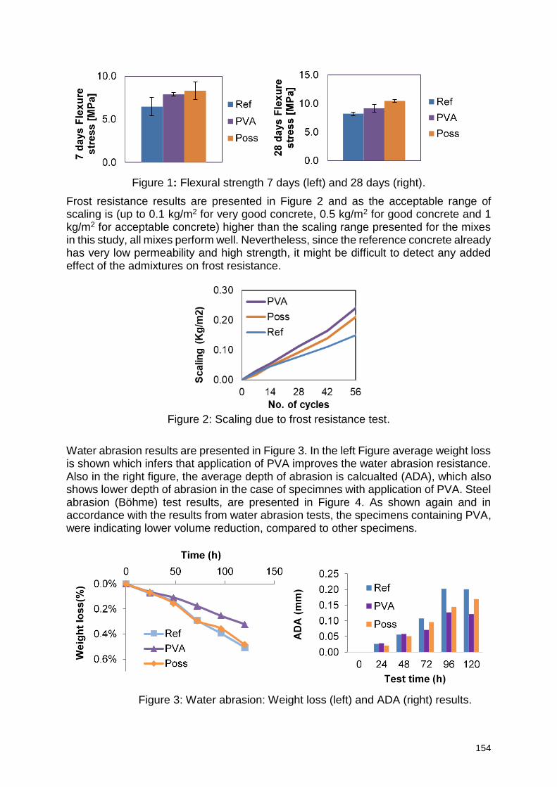
154
Figure 1: Flexural strength 7 days (left) and 28 days (right).
Frost resistance results are presented in Figure 2 and as the acceptable range of scaling is (up to 0.1 kg/m2 for very good concrete, 0.5 kg/m2 for good concrete and 1 kg/m2 for acceptable concrete) higher than the scaling range presented for the mixes in this study, all mixes perform well. Nevertheless, since the reference concrete already has very low permeability and high strength, it might be difficult to detect any added effect of the admixtures on frost resistance.
Figure 2: Scaling due to frost resistance test.
Water abrasion results are presented in Figure 3. In the left Figure average weight loss is shown which infers that application of PVA improves the water abrasion resistance. Also in the right figure, the average depth of abrasion is calcualted (ADA), which also shows lower depth of abrasion in the case of specimnes with application of PVA. Steel abrasion (Böhme) test results, are presented in Figure 4. As shown again and in accordance with the results from water abrasion tests, the specimens containing PVA, were indicating lower volume reduction, compared to other specimens.
Figure 3: Water abrasion: Weight loss (left) and ADA (right) results.
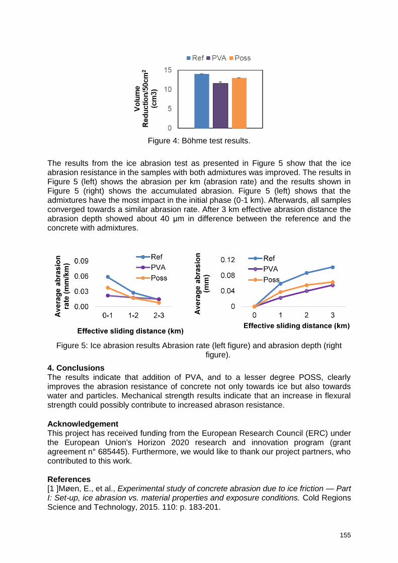
155
Figure 4: Böhme test results.
The results from the ice abrasion test as presented in Figure 5 show that the ice abrasion resistance in the samples with both admixtures was improved. The results in Figure 5 (left) shows the abrasion per km (abrasion rate) and the results shown in Figure 5 (right) shows the accumulated abrasion. Figure 5 (left) shows that the admixtures have the most impact in the initial phase (0-1 km). Afterwards, all samples converged towards a similar abrasion rate. After 3 km effective abrasion distance the abrasion depth showed about 40 μm in difference between the reference and the concrete with admixtures.
Figure 5: Ice abrasion results Abrasion rate (left figure) and abrasion depth (right
figure).
4. Conclusions The results indicate that addition of PVA, and to a lesser degree POSS, clearly improves the abrasion resistance of concrete not only towards ice but also towards water and particles. Mechanical strength results indicate that an increase in flexural strength could possibly contribute to increased abrason resistance.
Acknowledgement This project has received funding from the European Research Council (ERC) under the European Union's Horizon 2020 research and innovation program (grant agreement n° 685445). Furthermore, we would like to thank our project partners, who contributed to this work. References [1 ]Møen, E., et al., Experimental study of concrete abrasion due to ice friction — Part I: Set-up, ice abrasion vs. material properties and exposure conditions. Cold Regions Science and Technology, 2015. 110: p. 183-201.
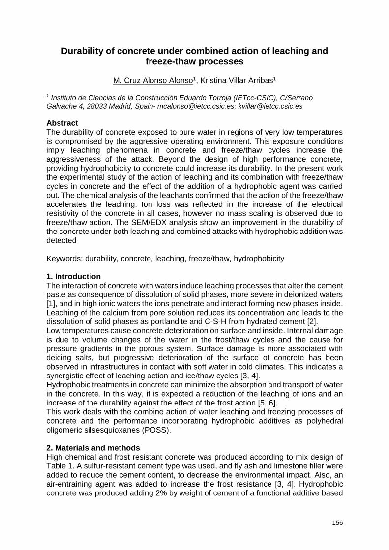
156
Durability of concrete under combined action of leaching and freeze-thaw processes
M. Cruz Alonso Alonso1, Kristina Villar Arribas1
1 Instituto de Ciencias de la Construcción Eduardo Torroja (IETcc-CSIC), C/Serrano Galvache 4, 28033 Madrid, Spain- [email protected]; [email protected]
Abstract The durability of concrete exposed to pure water in regions of very low temperatures is compromised by the aggressive operating environment. This exposure conditions imply leaching phenomena in concrete and freeze/thaw cycles increase the aggressiveness of the attack. Beyond the design of high performance concrete, providing hydrophobicity to concrete could increase its durability. In the present work the experimental study of the action of leaching and its combination with freeze/thaw cycles in concrete and the effect of the addition of a hydrophobic agent was carried out. The chemical analysis of the leachants confirmed that the action of the freeze/thaw accelerates the leaching. Ion loss was reflected in the increase of the electrical resistivity of the concrete in all cases, however no mass scaling is observed due to freeze/thaw action. The SEM/EDX analysis show an improvement in the durability of the concrete under both leaching and combined attacks with hydrophobic addition was detected Keywords: durability, concrete, leaching, freeze/thaw, hydrophobicity 1. Introduction The interaction of concrete with waters induce leaching processes that alter the cement paste as consequence of dissolution of solid phases, more severe in deionized waters [1], and in high ionic waters the ions penetrate and interact forming new phases inside. Leaching of the calcium from pore solution reduces its concentration and leads to the dissolution of solid phases as portlandite and C-S-H from hydrated cement [2]. Low temperatures cause concrete deterioration on surface and inside. Internal damage is due to volume changes of the water in the frost/thaw cycles and the cause for pressure gradients in the porous system. Surface damage is more associated with deicing salts, but progressive deterioration of the surface of concrete has been observed in infrastructures in contact with soft water in cold climates. This indicates a synergistic effect of leaching action and ice/thaw cycles [3, 4]. Hydrophobic treatments in concrete can minimize the absorption and transport of water in the concrete. In this way, it is expected a reduction of the leaching of ions and an increase of the durability against the effect of the frost action [5, 6]. This work deals with the combine action of water leaching and freezing processes of concrete and the performance incorporating hydrophobic additives as polyhedral oligomeric silsesquioxanes (POSS). 2. Materials and methods High chemical and frost resistant concrete was produced according to mix design of Table 1. A sulfur-resistant cement type was used, and fly ash and limestone filler were added to reduce the cement content, to decrease the environmental impact. Also, an air-entraining agent was added to increase the frost resistance [3, 4]. Hydrophobic concrete was produced adding 2% by weight of cement of a functional additive based
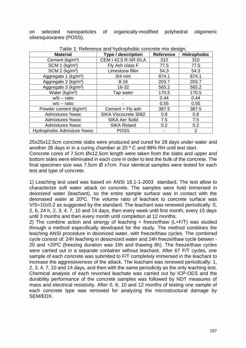
157
on selected nanoparticles of organically-modified polyhedral oligomeric silsesquioxanes (POSS).
Table 1: Reference and hydrophobic concrete mix design. Material Type / description Reference Hidrophobic
Cement (kg/m³) CEM I 42,5 R-SR 0/LA 310 310
SCM 1 (kg/m³) Fly Ash class F 77.5 77.5
SCM 2 (kg/m³) Limestone filler 54.3 54.3
Aggregate 1 (kg/m³) 0/4 mm 874.1 874.1
Aggregate 2 (kg/m³) 8-16 203.7 203.7
Aggregate 3 (kg/m³) 16-32 565.2 565.2
Water (kg/m³) Tap water 170.5 170.5
w/b – ratio - 0.44 0.44
w/c – ratio - 0.55 0.55
Powder content (kg/m³) Cement + Fly ash 387.5 387.5
Admixtures %woc SIKA Viscocrete 3082 0.8 0.8
Admixtures %woc SIKA Aer Solid 7.5 7.5
Admixtures %woc SIKA Retard 0.2 0.2
Hydrophobic Admixture %woc POSS - 2
25x25x12.5cm concrete slabs were produced and cured for 28 days under water and another 28 days in in a curing chamber at 20 º C and 98% RH until test start. Concrete cores of 7.5cm Øx12.5cm length were taken from the slabs and upper and bottom sides were eliminated in each core in order to test the bulk of the concrete. The final specimen size was 7.5cm Ø x7cm. Four identical samples were tested for each test and type of concrete. 1) Leaching test used was based on ANSI 16.1-1-2003 standard. The test allow to characterize soft water attack on concrete. The samples were hold immersed in deionized water (leachant), so the entire sample surface was in contact with the deionased water at 20ºC. The volume ratio of leachant to concrete surface was V/S=10±0.2 as suggested by the standard. The leachant was renewed periodically: 0, 2, 6, 24 h, 2, 3, 4, 7, 10 and 14 days, then every week until first month, every 15 days until 3 months and then every month until completion at 12 months. 2) The combine action and sinergy of leaching + freeze/thaw (L+F/T) was studied through a method especifically developed for the study. The method combines the leaching ANSI procedure in deionized water, with freeze/thaw cycles. The combined cycle consist of: 24h leaching in desionized water and 24h freeze/thaw cycle betwen -20 and +20ºC (freezing duration was 16h and thawing 8h). The freeze/thaw cycles were carried out in a separate container without leachant. After 67 F/T cycles, one sample of each concrete was submited to F/T completely immersed in the leachant to increase the aggressiveness of the attack. The leachant was renewed periodically: 1, 2, 3, 4, 7, 10 and 14 days, and then with the same periodicity as the only leaching test. Chemical analysis of each revomed leachate was carried out by ICP-OES and the durability performance of the concrete samples was followed by NDT measures of mass and electrical resistivity. After 0, 6, 10 and 12 months of testing one sample of each concrete type was removed for analyzing the microstructural damage by SEM/EDX.
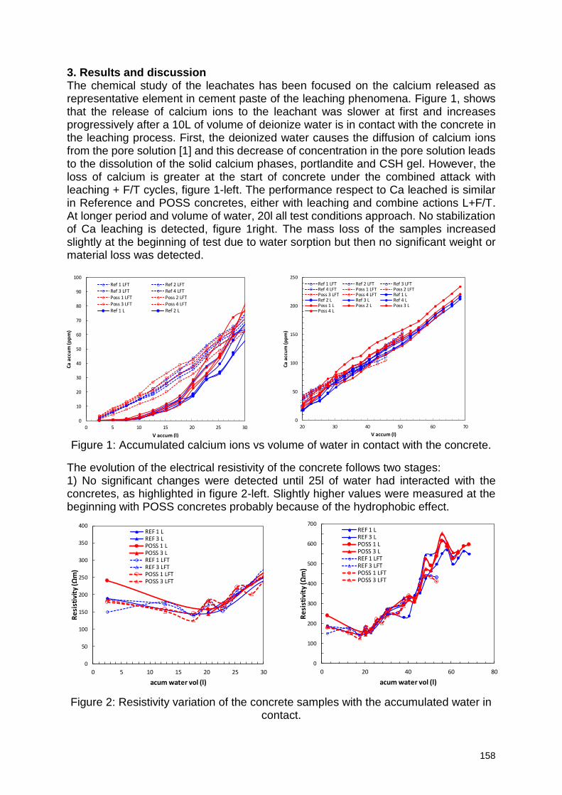
158
3. Results and discussion The chemical study of the leachates has been focused on the calcium released as representative element in cement paste of the leaching phenomena. Figure 1, shows that the release of calcium ions to the leachant was slower at first and increases progressively after a 10L of volume of deionize water is in contact with the concrete in the leaching process. First, the deionized water causes the diffusion of calcium ions from the pore solution [1] and this decrease of concentration in the pore solution leads to the dissolution of the solid calcium phases, portlandite and CSH gel. However, the loss of calcium is greater at the start of concrete under the combined attack with leaching + F/T cycles, figure 1-left. The performance respect to Ca leached is similar in Reference and POSS concretes, either with leaching and combine actions L+F/T. At longer period and volume of water, 20l all test conditions approach. No stabilization of Ca leaching is detected, figure 1right. The mass loss of the samples increased slightly at the beginning of test due to water sorption but then no significant weight or material loss was detected.
Figure 1: Accumulated calcium ions vs volume of water in contact with the concrete.
The evolution of the electrical resistivity of the concrete follows two stages: 1) No significant changes were detected until 25l of water had interacted with the concretes, as highlighted in figure 2-left. Slightly higher values were measured at the beginning with POSS concretes probably because of the hydrophobic effect.
Figure 2: Resistivity variation of the concrete samples with the accumulated water in
contact.
0
50
100
150
200
250
20 30 40 50 60 70
Ca a
ccu
m (p
pm
)
V accum (l)
Ref 1 LFT Ref 2 LFT Ref 3 LFTRef 4 LFT Poss 1 LFT Poss 2 LFTPoss 3 LFT Poss 4 LFT Ref 1 LRef 2 L Ref 3 L Ref 4 LPoss 1 L Poss 2 L Poss 3 LPoss 4 L
0
10
20
30
40
50
60
70
80
90
100
0 5 10 15 20 25 30
Ca a
ccu
m (
pp
m)
V accum (l)
Ref 1 LFT Ref 2 LFTRef 3 LFT Ref 4 LFTPoss 1 LFT Poss 2 LFTPoss 3 LFT Poss 4 LFTRef 1 L Ref 2 L
0
50
100
150
200
250
300
350
400
0 5 10 15 20 25 30
Re
sist
ivit
y (Ω
m)
acum water vol (l)
REF 1 LREF 3 LPOSS 1 LPOSS 3 LREF 1 LFTREF 3 LFTPOSS 1 LFTPOSS 3 LFT
0
100
200
300
400
500
600
700
0 20 40 60 80
Re
sist
ivit
y (Ω
m)
acum water vol (l)
REF 1 LREF 3 LPOSS 1 LPOSS 3 LREF 1 LFTREF 3 LFTPOSS 1 LFTPOSS 3 LFT
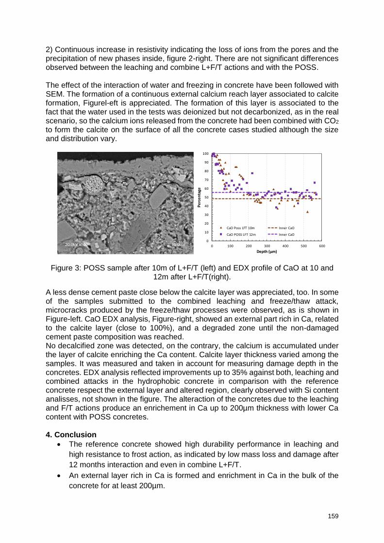
159
2) Continuous increase in resistivity indicating the loss of ions from the pores and the precipitation of new phases inside, figure 2-right. There are not significant differences observed between the leaching and combine L+F/T actions and with the POSS. The effect of the interaction of water and freezing in concrete have been followed with SEM. The formation of a continuous external calcium reach layer associated to calcite formation, Figurel-eft is appreciated. The formation of this layer is associated to the fact that the water used in the tests was deionized but not decarbonized, as in the real scenario, so the calcium ions released from the concrete had been combined with CO2 to form the calcite on the surface of all the concrete cases studied although the size and distribution vary.
Figure 3: POSS sample after 10m of L+F/T (left) and EDX profile of CaO at 10 and 12m after L+F/T(right).
A less dense cement paste close below the calcite layer was appreciated, too. In some of the samples submitted to the combined leaching and freeze/thaw attack, microcracks produced by the freeze/thaw processes were observed, as is shown in Figure-left. CaO EDX analysis, Figure-right, showed an external part rich in Ca, related to the calcite layer (close to 100%), and a degraded zone until the non-damaged cement paste composition was reached. No decalcified zone was detected, on the contrary, the calcium is accumulated under the layer of calcite enriching the Ca content. Calcite layer thickness varied among the samples. It was measured and taken in account for measuring damage depth in the concretes. EDX analysis reflected improvements up to 35% against both, leaching and combined attacks in the hydrophobic concrete in comparison with the reference concrete respect the external layer and altered region, clearly observed with Si content analisses, not shown in the figure. The alteraction of the concretes due to the leaching and F/T actions produce an enrichement in Ca up to 200µm thickness with lower Ca content with POSS concretes. 4. Conclusion
The reference concrete showed high durability performance in leaching and
high resistance to frost action, as indicated by low mass loss and damage after
12 months interaction and even in combine L+F/T.
An external layer rich in Ca is formed and enrichment in Ca in the bulk of the
concrete for at least 200µm.
0
10
20
30
40
50
60
70
80
90
100
0 100 200 300 400 500 600
Pe
rce
nta
ge
Depth (µm)
CaO Poss LFT 10m Inner CaO
CaO POSS LFT 12m Inner CaO
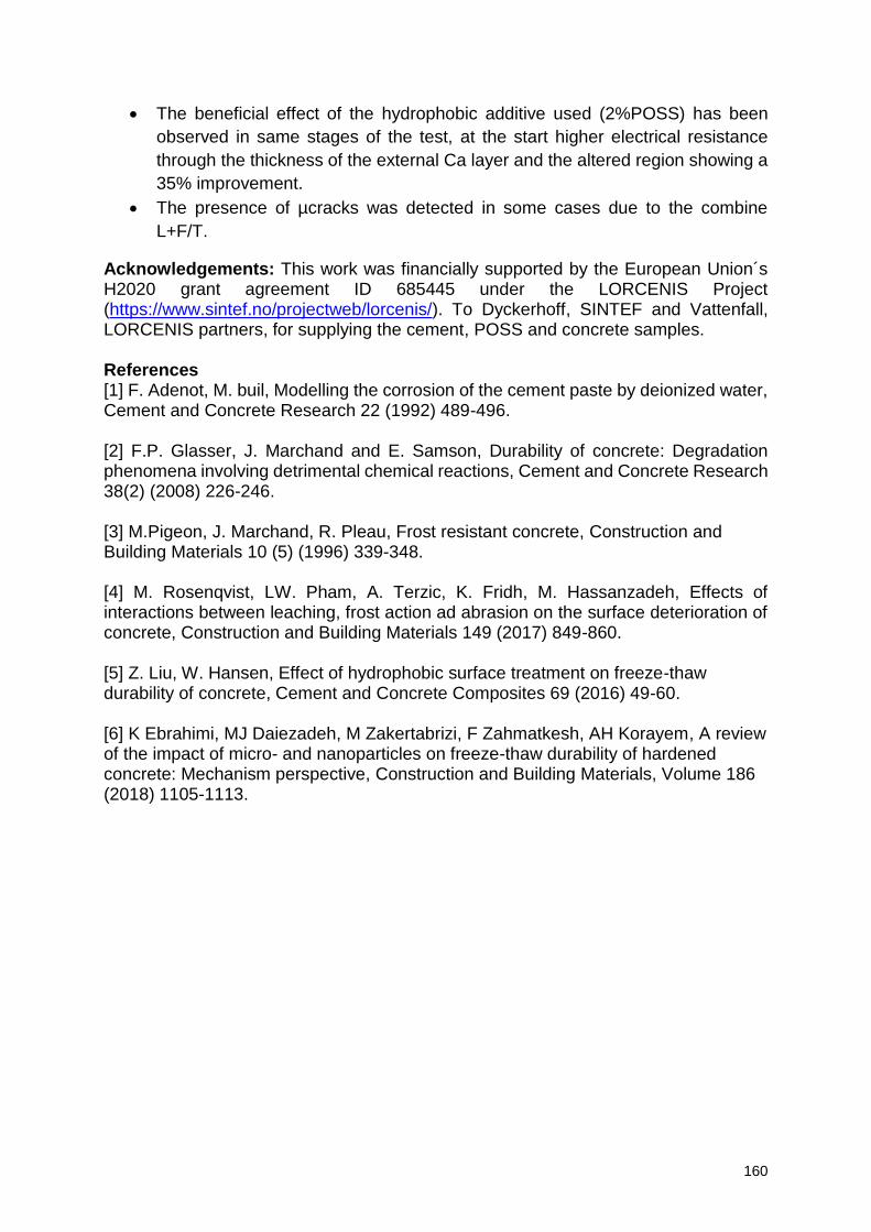
160
The beneficial effect of the hydrophobic additive used (2%POSS) has been
observed in same stages of the test, at the start higher electrical resistance
through the thickness of the external Ca layer and the altered region showing a
35% improvement.
The presence of µcracks was detected in some cases due to the combine
L+F/T.
Acknowledgements: This work was financially supported by the European Union´s H2020 grant agreement ID 685445 under the LORCENIS Project (https://www.sintef.no/projectweb/lorcenis/). To Dyckerhoff, SINTEF and Vattenfall, LORCENIS partners, for supplying the cement, POSS and concrete samples. References [1] F. Adenot, M. buil, Modelling the corrosion of the cement paste by deionized water, Cement and Concrete Research 22 (1992) 489-496. [2] F.P. Glasser, J. Marchand and E. Samson, Durability of concrete: Degradation phenomena involving detrimental chemical reactions, Cement and Concrete Research 38(2) (2008) 226-246. [3] M.Pigeon, J. Marchand, R. Pleau, Frost resistant concrete, Construction and Building Materials 10 (5) (1996) 339-348. [4] M. Rosenqvist, LW. Pham, A. Terzic, K. Fridh, M. Hassanzadeh, Effects of interactions between leaching, frost action ad abrasion on the surface deterioration of concrete, Construction and Building Materials 149 (2017) 849-860. [5] Z. Liu, W. Hansen, Effect of hydrophobic surface treatment on freeze-thaw durability of concrete, Cement and Concrete Composites 69 (2016) 49-60. [6] K Ebrahimi, MJ Daiezadeh, M Zakertabrizi, F Zahmatkesh, AH Korayem, A review of the impact of micro- and nanoparticles on freeze-thaw durability of hardened concrete: Mechanism perspective, Construction and Building Materials, Volume 186 (2018) 1105-1113.
161
Experiences gained from condition assessment and service life prediction of a marine concrete structure: practice versus theory
J. Gulikers1
1 Rijkswaterstaat-GPO, Ministry of Infrastructure and Water Management, Griffioenlaan 2, 3526 LA Utrecht, Netherlands – email: [email protected]
Abstract Based on the findings of extensive investigations performed on an existing marine concrete bridge at an age of 18 years, additional destructive and non-destructive investigations were performed at an age of 30 years to provide up-to-date quantitative information on the actual chloride ingress and the electrochemical state of the reinforcing steel. The detailed visual inspection didn’t reveal any areas suspect reinforcement corrosion, however the chloride contents found at the level of the reinforcing steel indicated a relatively high probability of corrosion. In contrast results of the non-destructive investigations indicated a largely passive state with incidentally onset of corrosion but at a very low corrosion rate. These contradictory findings raised considerable doubt on the actual level of the critical chloride content in this structure to be used both in condition assessment and in prediction of condition assessment based on a modelling approach. In this paper the results of the investigations will be presented and their interpretation regarding predictions based on modelling. Keywords: Assessment, reinforced concrete, chlorides, corrosion, prediction 1. Introduction For marine concrete structures reinforcement corrosion induced by penetrating chlorides is considered to be the major threat for long-term durability. Consequently, to allow for a pro-active maintenance strategy, a condition assessment usually will have to include determination of the extent of chloride ingress by drilling concrete cores. These semi-destructive investigations result in a number of chloride penetration profiles providing information on the current risk of reinforcement corrosion and the depth-dependent profile is often used for prediction over time of the chloride content at the level of the reinforcing steel as to quantify the probability of corrosion occurring. However, for most asset owners chloride profiling combined with prediction of chloride ingress over time is only performed on structures already showing visible evidence of reinforcement corrosion. Consequently, the added value of such investigations with respect to preventative maintenance and cost-savings will be limited. The more logical and cost-effective approach would be to quantify chloride ingress at predefined time intervals to update the predicted time of corrosion onset allowing timely preventive actions to be taken long before reinforcement corrosion actually starts. It is preferable that such a pro-active approach will be combined with largely non-destructive measurements, e.g. of cover depth, concrete resistivity and steel potential. 2. Description of the investigated marine bridge structure As part of a national project on durability of concrete exposed to a marine environment in 2002 a condition assessment was made on a number of reinforced concrete structures in the Netherlands. Among these structures the bridge over the storm surge
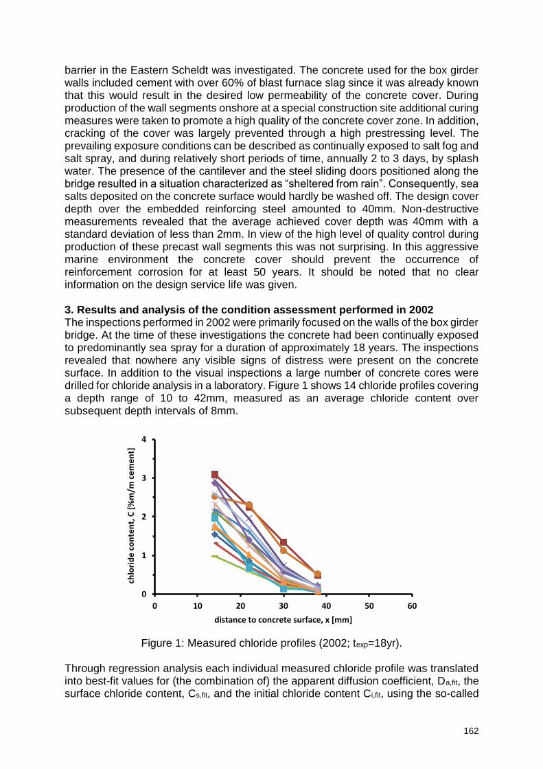
162
barrier in the Eastern Scheldt was investigated. The concrete used for the box girder walls included cement with over 60% of blast furnace slag since it was already known that this would result in the desired low permeability of the concrete cover. During production of the wall segments onshore at a special construction site additional curing measures were taken to promote a high quality of the concrete cover zone. In addition, cracking of the cover was largely prevented through a high prestressing level. The prevailing exposure conditions can be described as continually exposed to salt fog and salt spray, and during relatively short periods of time, annually 2 to 3 days, by splash water. The presence of the cantilever and the steel sliding doors positioned along the bridge resulted in a situation characterized as “sheltered from rain”. Consequently, sea salts deposited on the concrete surface would hardly be washed off. The design cover depth over the embedded reinforcing steel amounted to 40mm. Non-destructive measurements revealed that the average achieved cover depth was 40mm with a standard deviation of less than 2mm. In view of the high level of quality control during production of these precast wall segments this was not surprising. In this aggressive marine environment the concrete cover should prevent the occurrence of reinforcement corrosion for at least 50 years. It should be noted that no clear information on the design service life was given. 3. Results and analysis of the condition assessment performed in 2002 The inspections performed in 2002 were primarily focused on the walls of the box girder bridge. At the time of these investigations the concrete had been continually exposed to predominantly sea spray for a duration of approximately 18 years. The inspections revealed that nowhere any visible signs of distress were present on the concrete surface. In addition to the visual inspections a large number of concrete cores were drilled for chloride analysis in a laboratory. Figure 1 shows 14 chloride profiles covering a depth range of 10 to 42mm, measured as an average chloride content over subsequent depth intervals of 8mm.
Figure 1: Measured chloride profiles (2002; texp=18yr).
Through regression analysis each individual measured chloride profile was translated into best-fit values for (the combination of) the apparent diffusion coefficient, Da,fit, the surface chloride content, Cs,fit, and the initial chloride content Ci,fit, using the so-called
0
1
2
3
4
0 10 20 30 40 50 60
chlo
rid
e c
on
ten
t, C
[%
m/m
ce
me
nt]
distance to concrete surface, x [mm]
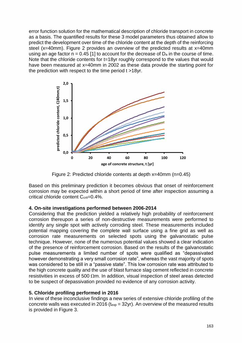
163
error function solution for the mathematical description of chloride transport in concrete as a basis. The quantified results for these 3 model parameters thus obtained allow to predict the development over time of the chloride content at the depth of the reinforcing steel (x=40mm). Figure 2 provides an overview of the predicted results at x=40mm using an age factor n = 0.45 [1] to account for the decrease of Da in the course of time. Note that the chloride contents for t=18yr roughly correspond to the values that would have been measured at x=40mm in 2002 as these data provide the starting point for the prediction with respect to the time period t >18yr.
Figure 2: Predicted chloride contents at depth x=40mm (n=0.45)
Based on this preliminary prediction it becomes obvious that onset of reinforcement corrosion may be expected within a short period of time after inspection assuming a critical chloride content Ccrit=0.4%. 4. On-site investigations performed between 2006-2014 Considering that the prediction yielded a relatively high probability of reinforcement corrosion thereupon a series of non-destructive measurements were performed to identify any single spot with actively corroding steel. These measurements included potential mapping covering the complete wall surface using a fine grid as well as corrosion rate measurements on selected spots using the galvanostatic pulse technique. However, none of the numerous potential values showed a clear indication of the presence of reinforcement corrosion. Based on the results of the galvanostatic pulse measurements a limited number of spots were qualified as “depassivated however demonstrating a very small corrosion rate”, whereas the vast majority of spots was considered to be still in a “passive state”. This low corrosion rate was attributed to the high concrete quality and the use of blast furnace slag cement reflected in concrete
resistivities in excess of 500 m. In addition, visual inspection of steel areas detected to be suspect of depassivation provided no evidence of any corrosion activity. 5. Chloride profiling performed in 2016 In view of these inconclusive findings a new series of extensive chloride profiling of the concrete walls was executed in 2016 (texp = 32yr). An overview of the measured results is provided in Figure 3.
0,0
0,5
1,0
1,5
2,0
0 20 40 60 80 100 120
pre
dic
ted
ch
lori
de
co
nte
nt,
C(4
0m
m;t
)
age of concrete structure, t [yr]
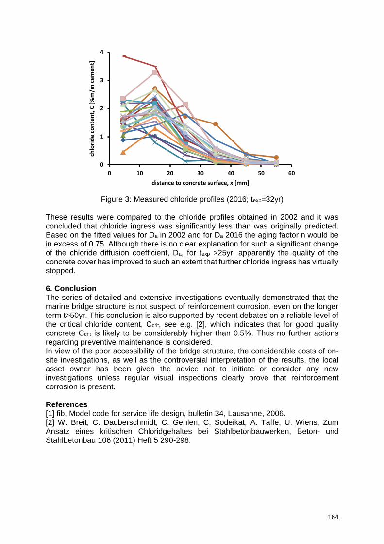
164
Figure 3: Measured chloride profiles (2016; texp=32yr)
These results were compared to the chloride profiles obtained in 2002 and it was concluded that chloride ingress was significantly less than was originally predicted. Based on the fitted values for Da in 2002 and for Da 2016 the aging factor n would be in excess of 0.75. Although there is no clear explanation for such a significant change of the chloride diffusion coefficient, Da, for texp >25yr, apparently the quality of the concrete cover has improved to such an extent that further chloride ingress has virtually stopped. 6. Conclusion The series of detailed and extensive investigations eventually demonstrated that the marine bridge structure is not suspect of reinforcement corrosion, even on the longer term t>50yr. This conclusion is also supported by recent debates on a reliable level of the critical chloride content, Ccrit, see e.g. [2], which indicates that for good quality concrete Ccrit is likely to be considerably higher than 0.5%. Thus no further actions regarding preventive maintenance is considered. In view of the poor accessibility of the bridge structure, the considerable costs of on-site investigations, as well as the controversial interpretation of the results, the local asset owner has been given the advice not to initiate or consider any new investigations unless regular visual inspections clearly prove that reinforcement corrosion is present. References [1] fib, Model code for service life design, bulletin 34, Lausanne, 2006. [2] W. Breit, C. Dauberschmidt, C. Gehlen, C. Sodeikat, A. Taffe, U. Wiens, Zum Ansatz eines kritischen Chloridgehaltes bei Stahlbetonbauwerken, Beton- und Stahlbetonbau 106 (2011) Heft 5 290-298.
0
1
2
3
4
0 10 20 30 40 50 60
chlo
rid
e c
on
ten
t, C
[%
m/m
ce
me
nt]
distance to concrete surface, x [mm]
165
The impact of carbonation on frost salt scaling of concrete with ground granulated blast-furnace slag
H. Vanoutrive1, Ö. Cizer2, P.Minne1, R. Veramme1, E. Gruyaert1
1 KU Leuven, Department of Civil Engineering, Construction TC, Structural Mechanics and Building Materials, Gebroeders De Smetstraat 1, 9000 Ghent, Belgium – email: [email protected]; [email protected]; [email protected]
2 KU Leuven, Department of Civil Engineering, Building Materials and Building Technology Section, Kasteelpark Arenberg 40 - bus 2448, 3001 Leuven, Belgium – email: [email protected]
Abstract Concrete structures need to resist various and severe environments which affect the durability of concrete leading ultimately to degradation of the cement matrix or the reinforcement. Such environments are characterized by fluctuating weather conditions (e.g. temperature and relative humidity) and the presence of chemical substances in various concentrations (e.g. chlorides and carbon dioxide). Current test methods used to determine the performance of concrete mixtures are based on single deterioration mechanisms although in real circumstances different degradation mechanisms occur simultaneously or consecutively. These combined deterioration mechanisms can either accelerate or delay each other resulting in an under- or overestimation of concrete’s performance. In order to achieve a more accurate service life prediction, the synergy between common degradation mechanisms needs to be investigated. This study focusses on the impact of carbonation on the frost salt scaling of concrete. Three concrete mixtures were subjected to accelerated carbonation in a 2% CO2
environment. As binder types, ordinary Portland cement (OPC) and OPC in combination with ground granulated blast-furnace slag (GGBFS) (OPC/GGBFS = 60/40 and 30/70) were used. After 81 days of accelerated carbonation, the samples were exposed to 3% NaCl-solution and subjected to 56 freeze-thaw cycles according to CEN/TS 12390-9. Based on the mass loss due to scaling, a comparison was made between carbonated and uncarbonated concrete. In addition, the impact of different replacement levels of GGBFS was investigated. Keywords: carbonation, frost salt scaling, concrete, ground granulated blast-furnace slag 1. Introduction In cold climates or cyclic cold winters, the use of deicing salts on road and walk ways is a common practice. However, the use of these deicing chemicals leads to progressive damage of the concrete surface which consists of the removal of small chips or flakes [1]. Studies on the resistance to frost salt scaling of concrete with GGBFS have been carried out and the impact depends mostly on the replacement level, tested surface and the occurrence of carbonation. In general, it is reported from experimental testing that slag concrete showed considerably more scaling than OPC concrete [1, 2]. Only in case of small replacement levels ≤ 25%, an increased resistance is observed [2]. The inferior performance of slag concrete compared to OPC conflicts with the conclusions of Çopuroğlu [3]. He assessed the local micromechanical properties of 1 year old OPC and slag concrete and modelled frost salt scaling with
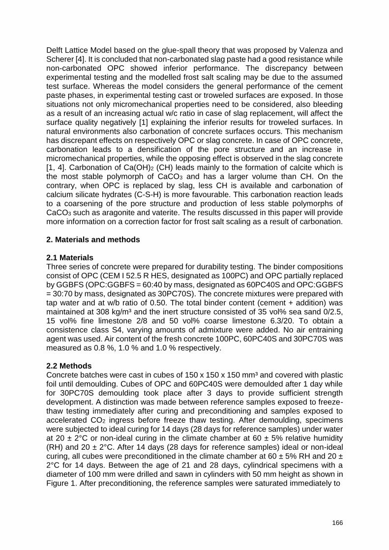
166
Delft Lattice Model based on the glue-spall theory that was proposed by Valenza and Scherer [4]. It is concluded that non-carbonated slag paste had a good resistance while non-carbonated OPC showed inferior performance. The discrepancy between experimental testing and the modelled frost salt scaling may be due to the assumed test surface. Whereas the model considers the general performance of the cement paste phases, in experimental testing cast or troweled surfaces are exposed. In those situations not only micromechanical properties need to be considered, also bleeding as a result of an increasing actual w/c ratio in case of slag replacement, will affect the surface quality negatively [1] explaining the inferior results for troweled surfaces. In natural environments also carbonation of concrete surfaces occurs. This mechanism has discrepant effects on respectively OPC or slag concrete. In case of OPC concrete, carbonation leads to a densification of the pore structure and an increase in micromechanical properties, while the opposing effect is observed in the slag concrete [1, 4]. Carbonation of Ca(OH)2 (CH) leads mainly to the formation of calcite which is the most stable polymorph of CaCO3 and has a larger volume than CH. On the contrary, when OPC is replaced by slag, less CH is available and carbonation of calcium silicate hydrates (C-S-H) is more favourable. This carbonation reaction leads to a coarsening of the pore structure and production of less stable polymorphs of CaCO3 such as aragonite and vaterite. The results discussed in this paper will provide more information on a correction factor for frost salt scaling as a result of carbonation. 2. Materials and methods 2.1 Materials Three series of concrete were prepared for durability testing. The binder compositions consist of OPC (CEM I 52.5 R HES, designated as 100PC) and OPC partially replaced by GGBFS (OPC:GGBFS = 60:40 by mass, designated as 60PC40S and OPC:GGBFS = 30:70 by mass, designated as 30PC70S). The concrete mixtures were prepared with tap water and at w/b ratio of 0.50. The total binder content (cement + addition) was maintained at 308 kg/m³ and the inert structure consisted of 35 vol% sea sand 0/2.5, 15 vol% fine limestone 2/8 and 50 vol% coarse limestone 6.3/20. To obtain a consistence class S4, varying amounts of admixture were added. No air entraining agent was used. Air content of the fresh concrete 100PC, 60PC40S and 30PC70S was measured as 0.8 %, 1.0 % and 1.0 % respectively. 2.2 Methods Concrete batches were cast in cubes of 150 x 150 x 150 mm³ and covered with plastic foil until demoulding. Cubes of OPC and 60PC40S were demoulded after 1 day while for 30PC70S demoulding took place after 3 days to provide sufficient strength development. A distinction was made between reference samples exposed to freeze-thaw testing immediately after curing and preconditioning and samples exposed to accelerated CO2 ingress before freeze thaw testing. After demoulding, specimens were subjected to ideal curing for 14 days (28 days for reference samples) under water at 20 ± 2°C or non-ideal curing in the climate chamber at 60 ± 5% relative humidity (RH) and 20 ± 2°C. After 14 days (28 days for reference samples) ideal or non-ideal curing, all cubes were preconditioned in the climate chamber at 60 ± 5% RH and 20 ± 2°C for 14 days. Between the age of 21 and 28 days, cylindrical specimens with a diameter of 100 mm were drilled and sawn in cylinders with 50 mm height as shown in Figure 1. After preconditioning, the reference samples were saturated immediately to
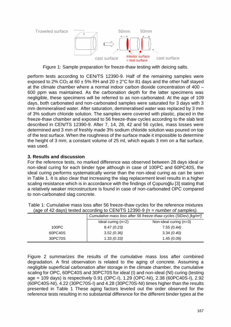
167
Figure 1: Sample preparation for freeze-thaw testing with deicing salts.
perform tests according to CEN/TS 12390-9. Half of the remaining samples were exposed to 2% CO2 at 60 ± 5% RH and 20 ± 2°C for 81 days and the other half stayed at the climate chamber where a normal indoor carbon dioxide concentration of 400 – 600 ppm was maintained. As the carbonation depth for the latter specimens was negligible, these specimens will be referred to as non-carbonated. At the age of 109 days, both carbonated and non-carbonated samples were saturated for 3 days with 3 mm demineralised water. After saturation, demineralised water was replaced by 3 mm of 3% sodium chloride solution. The samples were covered with plastic, placed in the freeze-thaw chamber and exposed to 56 freeze-thaw cycles according to the slab test described in CEN/TS 12390-9. After 7, 14, 28, 42 and 56 cycles, mass losses were determined and 3 mm of freshly made 3% sodium chloride solution was poured on top of the test surface. When the roughness of the surface made it impossible to determine the height of 3 mm, a constant volume of 25 ml, which equals 3 mm on a flat surface, was used. 3. Results and discussion For the reference tests, no marked difference was observed between 28 days ideal or non-ideal curing for each binder type although in case of 100PC and 60PC40S, the ideal curing performs systematically worse than the non-ideal curing as can be seen in Table 1. It is also clear that increasing the slag replacement level results in a higher scaling resistance which is in accordance with the findings of Çopuroğlu [3] stating that a relatively weaker microstructure is found in case of non-carbonated OPC compared to non-carbonated slag concrete. Table 1: Cumulative mass loss after 56 freeze-thaw cycles for the reference mixtures
(age of 42 days) tested according to CEN/TS 12390-9 (n = number of samples). Cumulative mass loss after 56 freeze-thaw cycles (StDev) [kg/m²]
Ideal curing (n=2) Non-ideal curing (n=3)
100PC 8.47 (0.23) 7.55 (0.44)
60PC40S 3.52 (0.36) 3.34 (0.40)
30PC70S 1.33 (0.33) 1.45 (0.09)
Figure 2 summarizes the results of the cumulative mass loss after combined degradation. A first observation is related to the aging of concrete. Assuming a negligible superficial carbonation after storage in the climate chamber, the cumulative scaling for OPC, 60PC40S and 30PC70S for ideal (I) and non-ideal (NI) curing (testing age = 109 days) is respectively 0.91 (OPC-I), 1.29 (OPC-NI), 2.38 (60PC40S-I), 2.92 (60PC40S-NI), 4.22 (30PC70S-I) and 4.28 (30PC70S-NI) times higher than the results presented in Table 1 These aging factors leveled out the order observed for the reference tests resulting in no substantial difference for the different binder types at the
Troweled surface 50mm 50mm
cast surface cast surface Interior surface = test surface
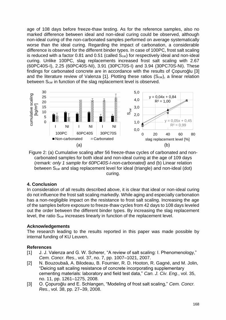
168
age of 108 days before freeze-thaw testing. As for the reference samples, also no marked difference between ideal and non-ideal curing could be observed, although non-ideal curing of the non-carbonated samples performed on average systematically worse than the ideal curing. Regarding the impact of carbonation, a considerable difference is observed for the different binder types. In case of 100PC, frost salt scaling is reduced with a factor 0.81 and 0.51 (called Scar) for respectively ideal and non-ideal curing. Unlike 100PC, slag replacements increased frost salt scaling with 2.67 (60PC40S-I), 2.25 (60PC40S-NI), 3.91 (30PC70S-I) and 3.94 (30PC70S-NI). These findings for carbonated concrete are in accordance with the results of Çopuroğlu [3] and the literature review of Valenza [1]. Plotting these ratios (Scar), a linear relation between Scar in function of the slag replacement level is observed.
(a) (b)
Figure 2: (a) Cumulative scaling after 56 freeze-thaw cycles of carbonated and non-carbonated samples for both ideal and non-ideal curing at the age of 109 days (remark: only 1 sample for 60PC40S-I-non-carbonated) and (b) Linear relation between Scar and slag replacement level for ideal (triangle) and non-ideal (dot)
curing. 4. Conclusion In consideration of all results described above, it is clear that ideal or non-ideal curing do not influence the frost salt scaling markedly. While aging and especially carbonation has a non-negligible impact on the resistance to frost salt scaling. Increasing the age of the samples before exposure to freeze-thaw cycles from 42 days to 108 days leveled out the order between the different binder types. By increasing the slag replacement level, the ratio Scar increases linearly in function of the replacement level. Acknowledgements The research leading to the results reported in this paper was made possible by internal funding of KU Leuven. References [1] J. J. Valenza and G. W. Scherer, “A review of salt scaling: I. Phenomenology,”
Cem. Concr. Res., vol. 37, no. 7, pp. 1007–1021, 2007. [2] N. Bouzoubaâ, A. Bilodeau, B. Fournier, R. D. Hooton, R. Gagné, and M. Jolin,
“Deicing salt scaling resistance of concrete incorporating supplementary cementing materials: laboratory and field test data,” Can. J. Civ. Eng., vol. 35, no. 11, pp. 1261–1275, 2008.
[3] O. Çopuroğlu and E. Schlangen, “Modeling of frost salt scaling,” Cem. Concr. Res., vol. 38, pp. 27–39, 2008.
0
5
10
15
20
25
30
I NI I NI I NI
100PC 60PC40S 30PC70S
cum
ula
tive s
calin
g
[kg
/m²]
Non-carbonated Carbonated
y = 0,04x + 0,84R² = 1,00
y = 0,05x + 0,45R² = 0,99
0,0
1,0
2,0
3,0
4,0
5,0
0 20 40 60 80
Scar
slag replacement level [%]

169
[4] J. J. Valenza and G. W. Scherer, “Mechanisms of salt scaling,” Mater. Struct., vol. 38, pp. 479–488, 2005.
170
Characterizing the Fatigue Behavior of High-Performance Concrete for Wind Energy Structures
V. Frei1, M. Thiele1, S. Pirskawetz1, B. Meng1, A. Rogge1
1 Bundesanstalt für Materialforschung und -prüfung (BAM), Unter den Eichen 87, 12205 Berlin, Germany – [email protected]; [email protected]; [email protected]; [email protected]; [email protected]
Abstract Severe mechanical fatigue conditions for worldwide proliferating windfarms are a major challenge for high-performance concrete in towers, connecting joints and foundations of wind turbines. High-performance concrete offers potential for the application in offshore windfarms, not only regarding its good mechanical, but also chemical resistivity due to low diffusivity in the highly densified microstructure. For a more reliable fatigue assessment, monitoring based on nondestructive testing can be a valuable complement to design rules. Both approaches demand reliable experimental data, information about scalability and the development of standardized testing methods. This article presents results of an ongoing research program of BAM (Bundesanstalt für Materialforschung und -prüfung), which is a part of a joint national project (WinConFat) funded by the German Federal Ministry for Economic Affairs and Energy. The subproject implemented by BAM examines the fatigue behavior in dependence of size and slenderness for varying concrete strength at different stress levels. Besides fatigue strength, nondestructive testing is carried out additionally. Methods used are strain measurement and ultrasonic testing. The change of strain, stiffness and ultrasonic pulse velocity in the fatigue process is discussed. Results disclose a deeper insight into the damage process under cyclic loading of high-performance concrete and contribute to improve nondestructive monitoring.
1. Introduction High-performance concrete offers superior advantages concerning logistics, production, maintenance and durability under severe conditions. Thus, it is an increasingly relevant material for wind turbine towers. Fatigue, caused by cyclic loading from wind and waves, is of central relevance for the design of wind turbine towers or gravity-based foundations [1]. Because of the most fundamental role of these structures and the high cost of retrofitting and repair a reliable prediction of the fatigue life and its characterization with damage parameters is necessary. The amendment of tests on high-strength concrete to first fatigue design rules (Model Code 1990) was implemented in the improved Model Code 2010 [2]. A more detailed analysis, considering the impact of material, specimen geometry and load conditions on fatigue strength is expected to improve the existing design rules. To supplement these design rules, damage variables [3] derived from nondestructive testing (NDT) can be considered. Potential NDT parameters are strain [4] and ultrasonic velocity [5, 6]. For real life application these NDT parameters can be correlated to damage variables and influences of material, load, test and geometrical conditions need a better understanding. The joint project WinConFat, funded by the 6th Energy Research Program of the Federal Government of Germany, focuses on the fatigue strength in compression of high-strength concrete by systematically varying concrete strength, specimen geometry, load and test conditions. In a subproject, the department “Safety of
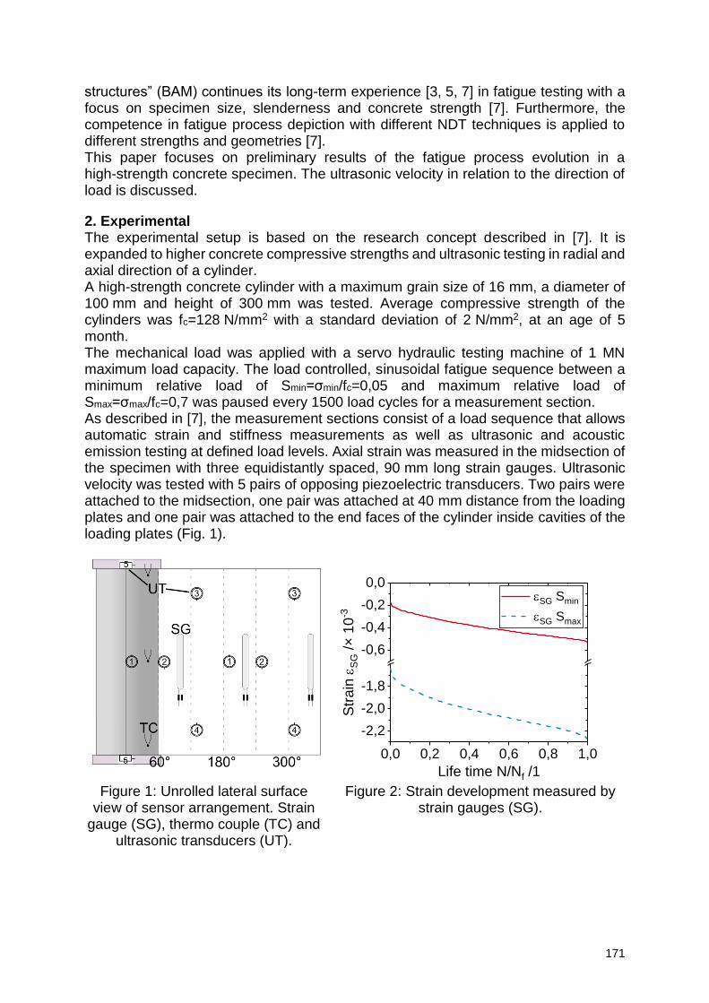
171
structures” (BAM) continues its long-term experience [3, 5, 7] in fatigue testing with a focus on specimen size, slenderness and concrete strength [7]. Furthermore, the competence in fatigue process depiction with different NDT techniques is applied to different strengths and geometries [7]. This paper focuses on preliminary results of the fatigue process evolution in a high-strength concrete specimen. The ultrasonic velocity in relation to the direction of load is discussed.
2. Experimental The experimental setup is based on the research concept described in [7]. It is expanded to higher concrete compressive strengths and ultrasonic testing in radial and axial direction of a cylinder. A high-strength concrete cylinder with a maximum grain size of 16 mm, a diameter of 100 mm and height of 300 mm was tested. Average compressive strength of the cylinders was fc=128 N/mm2 with a standard deviation of 2 N/mm2, at an age of 5 month. The mechanical load was applied with a servo hydraulic testing machine of 1 MN maximum load capacity. The load controlled, sinusoidal fatigue sequence between a minimum relative load of Smin=σmin/fc=0,05 and maximum relative load of Smax=σmax/fc=0,7 was paused every 1500 load cycles for a measurement section. As described in [7], the measurement sections consist of a load sequence that allows automatic strain and stiffness measurements as well as ultrasonic and acoustic emission testing at defined load levels. Axial strain was measured in the midsection of the specimen with three equidistantly spaced, 90 mm long strain gauges. Ultrasonic velocity was tested with 5 pairs of opposing piezoelectric transducers. Two pairs were attached to the midsection, one pair was attached at 40 mm distance from the loading plates and one pair was attached to the end faces of the cylinder inside cavities of the loading plates (Fig. 1).
Figure 1: Unrolled lateral surface
view of sensor arrangement. Strain gauge (SG), thermo couple (TC) and
ultrasonic transducers (UT).
Figure 2: Strain development measured by strain gauges (SG).
0,0 0,2 0,4 0,6 0,8 1,0
-2,2
-2,0
-1,8
-0,6
-0,4
-0,2
0,0
Str
ain
eS
G /×
10
-3
Life time N/Nf /1
eSG Smin
eSG Smax
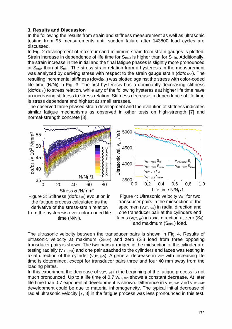
172
3. Results and Discussion In the following the results from strain and stiffness measurement as well as ultrasonic testing from 95 measurements until sudden failure after 143800 load cycles are discussed. In Fig. 2 development of maximum and minimum strain from strain gauges is plotted. Strain increase in dependence of life time for Smax is higher than for Smin. Additionally, the strain increase in the initial and the final fatigue phases is slightly more pronounced at Smax than at Smin. The stress strain relation from a hysteresis in the measurement was analyzed by deriving stress with respect to the strain gauge strain (dσ/dεSG). The
resulting incremental stiffness (dσ/dεSG) was plotted against the stress with color-coded
life time (N/Nf) in Fig. 3. The first hysteresis has a dominantly decreasing stiffness (dσ/dεSG) to stress relation, while any of the following hysteresis at higher life time have
an increasing stiffness to stress relation. Stiffness decrease in dependence of life time is stress dependent and highest at small stresses. The observed three phased strain development and the evolution of stiffness indicates similar fatigue mechanisms as observed in other tests on high-strength [7] and normal-strength concrete [8].
0 -20 -40 -60 -8035
40
45
50
55
ds
/de
/× 1
03 N
/mm
²
Stress s /N/mm²
0,00,10,20,30,40,50,60,70,80,9N/Nf /1
0,0 0,2 0,4 0,6 0,8 1,03500
4000
4500
5000
Ultra
so
nic
ve
l. v
UT /m
/s
Life time N/Nf /1
vUT, rad1 S0 vUT, rad2 S0
vUT, rad1 Smax vUT, rad2 Smax
vUT, ax5 S0
vUT, ax5 Smax
Figure 3: Stiffness (dσ/dεSG) evolution in
the fatigue process calculated as the derivative of the stress-strain relation
from the hysteresis over color-coded life time (N/Nf).
Figure 4: Ultrasonic velocity vUT for two transducer pairs in the midsection of the specimen (vUT, rad) in radial direction and one transducer pair at the cylinders end
faces (vUT, ax) in axial direction at zero (S0) and maximum (Smax) load.
The ultrasonic velocity between the transducer pairs is shown in Fig. 4. Results of ultrasonic velocity at maximum (Smax) and zero (S0) load from three opposing transducer pairs is shown. The two pairs arranged in the midsection of the cylinder are testing radially (vUT, rad) and one pair attached to the cylinders end faces was testing in axial direction of the cylinder (vUT, ax5). A general decrease in vUT with increasing life time is determined, except for transducer pairs three and four 40 mm away from the loading plates. In this experiment the decrease of vUT, rad in the beginning of the fatigue process is not much pronounced. Up to a life time of 0,7 vUT, rad shows a constant decrease. At later life time than 0,7 exponential development is shown. Difference in vUT, rad1 and vUT, rad2 development could be due to material inhomogeneity. The typical initial decrease of radial ultrasonic velocity [7, 8] in the fatigue process was less pronounced in this test.
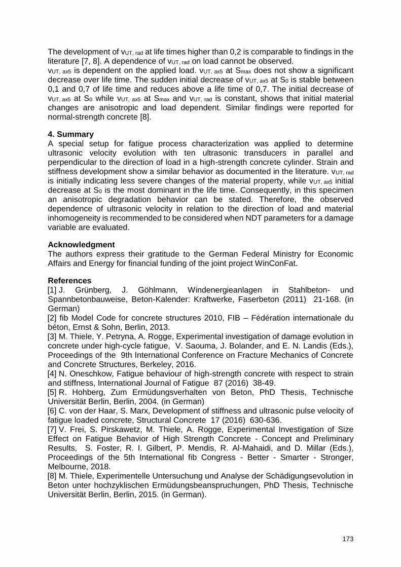
173
The development of vUT, rad at life times higher than 0,2 is comparable to findings in the literature [7, 8]. A dependence of vUT, rad on load cannot be observed. vUT, ax5 is dependent on the applied load. vUT, ax5 at Smax does not show a significant decrease over life time. The sudden initial decrease of vUT, ax5 at S0 is stable between 0,1 and 0,7 of life time and reduces above a life time of 0,7. The initial decrease of vUT, ax5 at S0 while vUT, ax5 at Smax and vUT, rad is constant, shows that initial material changes are anisotropic and load dependent. Similar findings were reported for normal-strength concrete [8].
4. Summary A special setup for fatigue process characterization was applied to determine ultrasonic velocity evolution with ten ultrasonic transducers in parallel and perpendicular to the direction of load in a high-strength concrete cylinder. Strain and stiffness development show a similar behavior as documented in the literature. vUT, rad is initially indicating less severe changes of the material property, while vUT, ax5 initial decrease at S0 is the most dominant in the life time. Consequently, in this specimen an anisotropic degradation behavior can be stated. Therefore, the observed dependence of ultrasonic velocity in relation to the direction of load and material inhomogeneity is recommended to be considered when NDT parameters for a damage variable are evaluated.
Acknowledgment The authors express their gratitude to the German Federal Ministry for Economic Affairs and Energy for financial funding of the joint project WinConFat.
References [1] J. Grünberg, J. Göhlmann, Windenergieanlagen in Stahlbeton- und Spannbetonbauweise, Beton-Kalender: Kraftwerke, Faserbeton (2011) 21-168. (in German) [2] fib Model Code for concrete structures 2010, FIB – Fédération internationale du béton, Ernst & Sohn, Berlin, 2013. [3] M. Thiele, Y. Petryna, A. Rogge, Experimental investigation of damage evolution in concrete under high-cycle fatigue, V. Saouma, J. Bolander, and E. N. Landis (Eds.), Proceedings of the 9th International Conference on Fracture Mechanics of Concrete and Concrete Structures, Berkeley, 2016. [4] N. Oneschkow, Fatigue behaviour of high-strength concrete with respect to strain and stiffness, International Journal of Fatigue 87 (2016) 38-49. [5] R. Hohberg, Zum Ermüdungsverhalten von Beton, PhD Thesis, Technische Universität Berlin, Berlin, 2004. (in German) [6] C. von der Haar, S. Marx, Development of stiffness and ultrasonic pulse velocity of fatigue loaded concrete, Structural Concrete 17 (2016) 630-636. [7] V. Frei, S. Pirskawetz, M. Thiele, A. Rogge, Experimental Investigation of Size Effect on Fatigue Behavior of High Strength Concrete - Concept and Preliminary Results, S. Foster, R. I. Gilbert, P. Mendis, R. Al-Mahaidi, and D. Millar (Eds.), Proceedings of the 5th International fib Congress - Better - Smarter - Stronger, Melbourne, 2018. [8] M. Thiele, Experimentelle Untersuchung und Analyse der Schädigungsevolution in Beton unter hochzyklischen Ermüdungsbeanspruchungen, PhD Thesis, Technische Universität Berlin, Berlin, 2015. (in German).
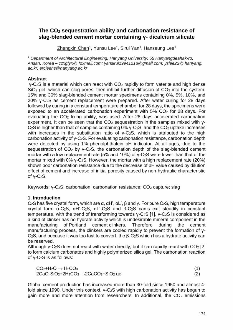
174
The CO2 sequestration ability and carbonation resistance of slag-blended cement mortar containing γ- dicalcium silicate
Zhengxin Chen1, Yunsu Lee1, Sirui Yan1, Hanseung Lee1
1 Department of Architectural Engineering, Hanyang University; 55 Hanyangdeahak-ro, Ansan, Korea – czxgfyx@ foxmail.com; [email protected]; yslee23@ hanyang. ac.kr; [email protected]
Abstract γ-C2S is a material which can react with CO2 rapidly to form vaterite and high dense SiO2 gel, which can clog pores, then inhibit further diffusion of CO2 into the system. 15% and 30% slag-blended cement mortar specimens containing 0%, 5%, 10%, and 20% γ-C2S as cement replacement were prepared. After water curing for 28 days followed by curing in a constant temperature chamber for 28 days, the specimens were exposed to an accelerated carbonation experiment with 5% CO2 for 28 days. For evaluating the CO2 fixing ability, was used. After 28 days accelerated carbonation experiment, It can be seen that the CO2 sequestration in the samples mixed with γ-C2S is higher than that of samples containing 0% γ-C2S, and the CO2 uptake increases with increases in the substitution ratio of γ-C2S, which is attributed to the high carbonation activity of γ-C2S. For evaluating carbonation resistance, carbonation depth were detected by using 1% phenolphthalein pH indicator. At all ages, due to the sequestration of CO2 by γ-C2S, the carbonation depth of the slag-blended cement mortar with a low replacement rate (5% and 10%) of γ-C2S were lower than that of the mortar mixed with 0% γ-C2S. However, the mortar with a high replacement rate (20%) shown poor carbonation resistance due to the decrease of pH value caused by dilution effect of cement and increase of initial porosity caused by non-hydraulic characteristic of γ-C2S. Keywords: γ-C2S; carbonation; carbonation resistance; CO2 capture; slag 1. Introduction C2S has five crystal form, which are α, αH’, αL’, β and γ. For pure C2S, high temperature crystal form α-C2S, αH’-C2S, αL’-C2S and β-C2S can’s exit steadily in constant temperature, with the trend of transforming towards γ-C2S [1]. γ-C2S is considered as a kind of clinker has no hydrate activity which is undesirable mineral component in the manufacturing of Portland cement clinkers. Therefore during the cement manufacturing process, the clinkers are cooled rapidly to prevent the formation of γ-C2S, and because it was too fast to convert, the β-C2S which has a hydrate activity can be reserved. Although γ-C2S does not react with water directly, but it can rapidly react with CO2 [2] to form calcium carbonates and highly polymerized silica gel. The carbonation reaction of γ-C2S is as follows:
Global cement production has increased more than 30-fold since 1950 and almost 4-fold since 1990. Under this context, γ-C2S with high carbonation activity has begun to gain more and more attention from researchers. In additional, the CO2 emissions
CO2+H2O → H2CO3 (1) 2CaO·SiO2+2H2CO3 →2CaCO3+SiO2 gel (2)
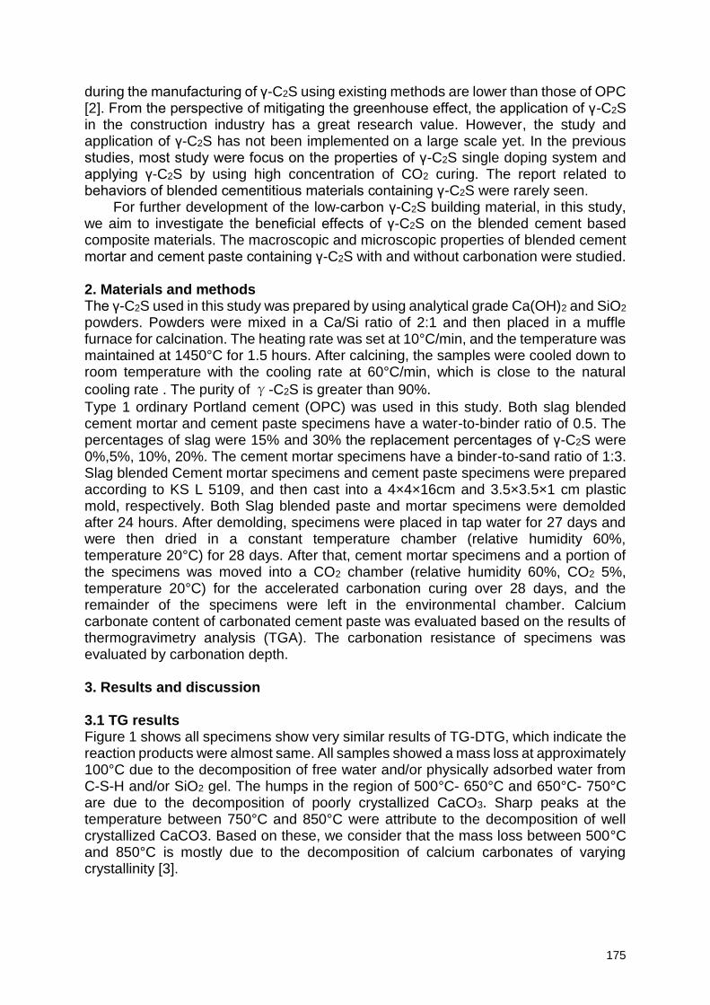
175
during the manufacturing of γ-C2S using existing methods are lower than those of OPC [2]. From the perspective of mitigating the greenhouse effect, the application of γ-C2S in the construction industry has a great research value. However, the study and application of γ-C2S has not been implemented on a large scale yet. In the previous studies, most study were focus on the properties of γ-C2S single doping system and applying γ-C2S by using high concentration of CO2 curing. The report related to behaviors of blended cementitious materials containing γ-C2S were rarely seen.
For further development of the low-carbon γ-C2S building material, in this study, we aim to investigate the beneficial effects of γ-C2S on the blended cement based composite materials. The macroscopic and microscopic properties of blended cement mortar and cement paste containing γ-C2S with and without carbonation were studied. 2. Materials and methods The γ-C2S used in this study was prepared by using analytical grade Ca(OH)2 and SiO2 powders. Powders were mixed in a Ca/Si ratio of 2:1 and then placed in a muffle furnace for calcination. The heating rate was set at 10°C/min, and the temperature was maintained at 1450°C for 1.5 hours. After calcining, the samples were cooled down to room temperature with the cooling rate at 60°C/min, which is close to the natural
cooling rate . The purity of γ-C2S is greater than 90%.
Type 1 ordinary Portland cement (OPC) was used in this study. Both slag blended cement mortar and cement paste specimens have a water-to-binder ratio of 0.5. The percentages of slag were 15% and 30% the replacement percentages of γ-C2S were 0%,5%, 10%, 20%. The cement mortar specimens have a binder-to-sand ratio of 1:3. Slag blended Cement mortar specimens and cement paste specimens were prepared according to KS L 5109, and then cast into a 4×4×16cm and 3.5×3.5×1 cm plastic mold, respectively. Both Slag blended paste and mortar specimens were demolded after 24 hours. After demolding, specimens were placed in tap water for 27 days and were then dried in a constant temperature chamber (relative humidity 60%, temperature 20°C) for 28 days. After that, cement mortar specimens and a portion of the specimens was moved into a CO2 chamber (relative humidity 60%, CO2 5%, temperature 20°C) for the accelerated carbonation curing over 28 days, and the remainder of the specimens were left in the environmental chamber. Calcium carbonate content of carbonated cement paste was evaluated based on the results of thermogravimetry analysis (TGA). The carbonation resistance of specimens was evaluated by carbonation depth. 3. Results and discussion 3.1 TG results Figure 1 shows all specimens show very similar results of TG-DTG, which indicate the reaction products were almost same. All samples showed a mass loss at approximately 100°C due to the decomposition of free water and/or physically adsorbed water from C-S-H and/or SiO2 gel. The humps in the region of 500°C- 650°C and 650°C- 750°C are due to the decomposition of poorly crystallized CaCO3. Sharp peaks at the temperature between 750°C and 850°C were attribute to the decomposition of well crystallized CaCO3. Based on these, we consider that the mass loss between 500°C and 850°C is mostly due to the decomposition of calcium carbonates of varying crystallinity [3].
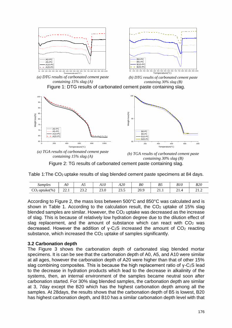
176
(a) DTG results of carbonated cement paste
containing 15% slag (A)
(b) DTG results of carbonated cement paste
containing 30% slag (B)
Figure 1: DTG results of carbonated cement paste containing slag.
(a) TGA results of carbonated cement paste
containing 15% slag (A)
(b) TGA results of carbonated cement paste
containing 30% slag (B)
Figure 2: TG results of carbonated cement paste containing slag.
Table 1:The CO2 uptake results of slag blended cement paste specimens at 84 days.
According to Figure 2, the mass loss between 500°C and 850°C was calculated and is shown in Table 1. According to the calculation result, the CO2 uptake of 15% slag blended samples are similar. However, the CO2 uptake was decreased as the increase of slag. This is because of relatively low hydration degree due to the dilution effect of slag replacement, and the amount of substance which can react with CO2 was decreased. However the addition of γ-C2S increased the amount of CO2 reacting substance, which increased the CO2 uptake of samples significantly.
3.2 Carbonation depth The Figure 3 shows the carbonation depth of carbonated slag blended mortar specimens. It is can be see that the carbonation depth of A0, A5, and A10 were similar at all ages, however the carbonation depth of A20 were higher than that of other 15% slag combining composites. This is because the high replacement ratio of γ-C2S lead to the decrease in hydration products which lead to the decrease in alkalinity of the systems, then, an internal environment of the samples became neutral soon after carbonation started. For 30% slag blended samples, the carbonation depth are similar at 3, 7day except the B20 which has the highest carbonation depth among all the samples. At 28days, the results shows that the carbonation depth of B5 is lowest, B20 has highest carbonation depth, and B10 has a similar carbonation depth level with that
50 100 150 200 250 300 350 400 450 500 550 600 650 700 750 800 850 900 950 1000
Temperature()
A0-PC
A5-PC
A10-PC
A20-PC
50 100 150 200 250 300 350 400 450 500 550 600 650 700 750 800 850 900 950 1000
Temperature()
B0-PC
B5-PC
B10-PC
B20-PC
0 200 400 600 800 1000
60
65
70
75
80
85
90
95
100
Temperature()
Weig
ht lo
ss(%
)
A0-PC
A5-PC
A10-PC
A20-PC
200 400 600 800 1000
60
80
100
Weig
ht lo
ss(%
)
Temperature()
B0-PC
B5-PC
B10-PC
B20-PC
Samples A0 A5 A10 A20 B0 B5 B10 B20
CO2 uptake(%) 22.1 23.2 23.0 23.5 20.9 21.1 21.4 21.2
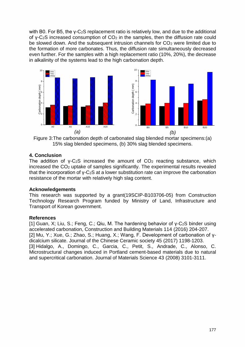
177
with B0. For B5, the γ-C2S replacement ratio is relatively low, and due to the additional of γ-C2S increased consumption of CO2 in the samples, then the diffusion rate could be slowed down. And the subsequent intrusion channels for CO2 were limited due to the formation of more carbonates. Thus, the diffusion rate simultaneously decreased even further. For the samples with a high replacement ratio (10%, 20%), the decrease in alkalinity of the systems lead to the high carbonation depth.
Figure 3:The carbonation depth of carbonated slag blended mortar specimens:(a) 15% slag blended specimens, (b) 30% slag blended specimens.
4. Conclusion The addition of γ-C2S increased the amount of CO2 reacting substance, which increased the CO2 uptake of samples significantly. The experimental results revealed that the incorporation of γ-C2S at a lower substitution rate can improve the carbonation resistance of the mortar with relatively high slag content. Acknowledgements This research was supported by a grant(19SCIP-B103706-05) from Construction Technology Research Program funded by Ministry of Land, Infrastructure and Transport of Korean government. References [1] Guan, X; Liu, S.; Feng, C.; Qiu, M. The hardening behavior of γ-C2S binder using accelerated carbonation, Construction and Building Materials 114 (2016) 204-207. [2] Mu, Y.; Xue, G.; Zhao, S.; Huang, X.; Wang, F. Development of carbonation of γ-dicalcium silicate. Journal of the Chinese Ceramic society 45 (2017) 1198-1203. [3] Hidalgo, A., Domingo, C., Garcia, C., Petit, S., Andrade, C., Alonso, C. Microstructural changes induced in Portland cement-based materials due to natural and supercritical carbonation. Journal of Materials Science 43 (2008) 3101-3111.
(a)
(b)
A0 A5 A10 A200
2
4
6
8
10
Ca
rbo
natio
n d
epth
( m
m)
3day
7day
28day
B0 B5 B10 B200
2
4
6
8
10
Carb
onatio
n d
epth
( m
m)
3day
7day
28day
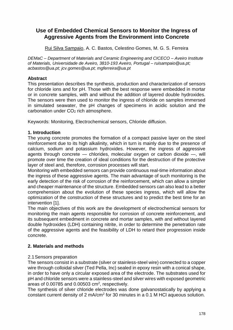
178
Use of Embedded Chemical Sensors to Monitor the Ingress of Aggressive Agents from the Environment into Concrete
Rui Silva Sampaio, A. C. Bastos, Celestino Gomes, M. G. S. Ferreira
DEMaC – Department of Materials and Ceramic Engineering and CICECO – Aveiro Institute of Materials, Universidade de Aveiro, 3810-193 Aveiro, Portugal – [email protected]; [email protected]; [email protected]; [email protected]
Abstract This presentation describes the synthesis, production and characterization of sensors for chloride ions and for pH. Those with the best response were embedded in mortar or in concrete samples, with and without the addition of layered double hydroxides. The sensors were then used to monitor the ingress of chloride on samples immersed in simulated seawater, the pH changes of specimens in acidic solution and the carbonation under CO2 rich atmosphere. Keywords: Monitoring, Electrochemical sensors, Chloride diffusion. 1. Introduction The young concrete promotes the formation of a compact passive layer on the steel reinforcement due to its high alkalinity, which in turn is mainly due to the presence of calcium, sodium and potassium hydroxides. However, the ingress of aggressive agents through concrete — chlorides, molecular oxygen or carbon dioxide —, will promote over time the creation of ideal conditions for the destruction of the protective layer of steel and, therefore, corrosion processes will start. Monitoring with embedded sensors can provide continuous real-time information about the ingress of these aggressive agents. The main advantage of such monitoring is the early detection of the risk of corrosion of the reinforcement, which can allow a simpler and cheaper maintenance of the structure. Embedded sensors can also lead to a better comprehension about the evolution of these species ingress, which will allow the optimization of the construction of these structures and to predict the best time for an intervention [1]. The main objectives of this work are the development of electrochemical sensors for monitoring the main agents responsible for corrosion of concrete reinforcement, and its subsequent embedment in concrete and mortar samples, with and without layered double hydroxides (LDH) containing nitrite, in order to determine the penetration rate of the aggressive agents and the feasibility of LDH to retard their progression inside concrete. 2. Materials and methods 2.1 Sensors preparation The sensors consist in a substrate (silver or stainless-steel wire) connected to a copper wire through colloidal silver (Ted Pella, Inc) sealed in epoxy resin with a conical shape, in order to have only a circular exposed area of the electrode. The substrates used for pH and chloride sensors were a stainless-steel and silver wires with exposed geometric areas of 0.00785 and 0.00503 cm2, respectively. The synthesis of silver chloride electrodes was done galvanostatically by applying a constant current density of 2 mA/cm2 for 30 minutes in a 0.1 M HCl aqueous solution.
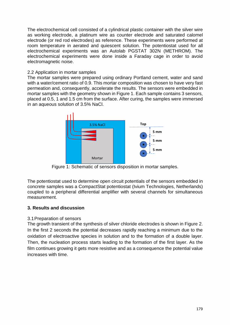
179
The electrochemical cell consisted of a cylindrical plastic container with the silver wire as working electrode, a platinum wire as counter electrode and saturated calomel electrode (or red rod electrodes) as reference. These experiments were performed at room temperature in aerated and quiescent solution. The potentiostat used for all electrochemical experiments was an Autolab PGSTAT 302N (METHROM). The electrochemical experiments were done inside a Faraday cage in order to avoid electromagnetic noise. 2.2 Application in mortar samples The mortar samples were prepared using ordinary Portland cement, water and sand with a water/cement ratio of 0.9. This mortar composition was chosen to have very fast permeation and, consequently, accelerate the results. The sensors were embedded in mortar samples with the geometry shown in Figure 1. Each sample contains 3 sensors, placed at 0.5, 1 and 1.5 cm from the surface. After curing, the samples were immersed in an aqueous solution of 3.5% NaCl.
Figure 1: Schematic of sensors disposition in mortar samples.
The potentiostat used to determine open circuit potentials of the sensors embedded in concrete samples was a CompactStat potentiostat (Ivium Technologies, Netherlands) coupled to a peripheral differential amplifier with several channels for simultaneous measurement. 3. Results and discussion 3.1 Preparation of sensors The growth transient of the synthesis of silver chloride electrodes is shown in Figure 2.
In the first 2 seconds the potential decreases rapidly reaching a minimum due to the
oxidation of electroactive species in solution and to the formation of a double layer.
Then, the nucleation process starts leading to the formation of the first layer. As the
film continues growing it gets more resistive and as a consequence the potential value
increases with time.
5 mm
5 mm
5 mm
Top 3.5% NaCl
Mortar
180
Figure 2: Time-potential transient of Ag/Cl growth.
The open circuit potentials for different chloride concentrations are represented in
Figure 3 (left), showing a typical potential response of an Ag/AgCl electrode to step
variation of chloride concentration of an order of magnitude between 1 and 10-4 M. As
can be seen, the response of the sensor is fast and stable over time. The calibration
curve is shown on the right. The curve does not change significantly with sensors
stored at pH=13 (buffer solution) to simulate the environment inside concrete.
Figure 3: Open circuit potentials (left) and calibration curve (right) of Ag/AgCl sensor
for different chloride concentrations.
3.2 Tests in mortar samples Figure 4 shows the change in chloride concentration measured by these sensors after the immersion of concrete samples in 3.5% NaCl solution. The chloride penetration is faster for sensors close to the surface and the sample containing LDH presents better results – slower ingress of chloride. The chloride concentration profile inside the concrete is shown in Figure 5, where 0 cm is the solution/concrete border and the other values are the concrete depth. The profiles change over time and present a maximum inside the concrete.
-0,05
0,00
0,05
0,10
0,15
0,20
0,25
0 200 400 600
E vs
. RR
E [V
]
Time [s]
y = -0,0503x - 0,0045R² = 0,9984
y = -0,0542x - 0,0104R² = 0,9994
y = -0,0538x - 0,0111R² = 0,9993
-0,05
0,00
0,05
0,10
0,15
0,20
0,25
-5 -3 -1 1
E vs
. SC
E [V
]
Chloride Conc. 10x [M]
day 0day 14day 28
0,1
0,12
0,14
0,16
0,18
0,2
0,22
0,24
0,26
0,28
0,3
0 500 1000 1500 2000
E vs
. RR
E [V
]
Time [s]
0,12
0,125
0,13
0 5 10
181
Figure 4: Chloride concentration evolution in mortar samples with and without (REF)
LDH.
Figure 5: Chloride profiles in mortar samples with and without (REF) LDH.
4. Conclusions Ag/AgCl sensors were produced and calibrated in solution. Then, they were embedded in mortar samples with and without LDH. After the immersion of the samples in 3.5% NaCl solution, the potentials of each sensor were measured at selected intervals and converted to chloride concentration inside concrete. Samples with layered double hydroxides presented slower ingress of chlorides. Acknowledgements This work is supported by the HORIZON 2020 Collaborative project “LORCENIS” (Long Lasting Reinforced Concrete for Energy Infrastructure under Severe Operating Conditions, Grant agreement nº 685445). References [1] P. Pedeferri, L. Bertolini, B. Elsener, E. Redaelli, R.B. Polder, Corrosion of
Steel in Concrete - Prevention, Diagnosis, Repair, Wiley-VCH, 2013.
0 2 4 6 8 10 12
10-4
10-3
10-2
10-1
REF
0.5 cm
1 cm
Conc. / M
Time / days
1.5 cm
0 2 4 6 8 10 12
1E-4
1E-3
0.01
0.1
0.5 cm
1 cm
Conc. / M
Time / days
1.5 cm
LDH
0.5 1.0 1.5
10-4
10-3
10-2
10-1
11d
8d
6d
4d
1d
[C
l- ] / M
Distance to surface / cm
LDH
15h
0 1 2
10-4
10-3
10-2
10-1
11d
8d
6d
4d
1d
[Cl- ]
/ M
Distance to surface / cm
REF
15h
182
Ice abrasion testing of HP concrete for offshore structures
Guzel Shamsutdinova1, Max A.N. Hendriks1,2, Kjell Tore Fossaa3, Stefan Jacobsen1
1 Norwegian University of Science and Technology, Department of Structural Engineering Richard Birkelandsvei 1A, 7491, Trondheim, Norway – email:
[email protected], [email protected], [email protected] 2 Delft University of Technology, Faculty of Civil Engineering and Geosciences, Stevinweg 1, 2628 CN, Delft, The Netherlands 3 KVAERNER Concrete Solutions, Lysaker, NORWAY – email: [email protected]
Abstract Offshore structures can be exposed to drifting sea ice. The wear (abrasion) of the concrete surface caused by the mechanical contact between ice and concrete is in the order of 0.1–1 mm per year. The concrete-ice abrasion laboratory at NTNU, and results of our recent research of the laboratory simulation of concrete-ice abrasion showed average abrasion depths of 0.01–0.35 mm for high-performance concrete after 3 kilometres of sliding ice, a severe-mild wear-transition, that abrasion is related to cutting of peaks, formation of valleys and aggregate protrusion by wear of ITZ. Keywords: Concrete, abrasion, ice, experiment.
1. Introduction In the late 1980-s, extensive research into the concrete-ice abrasion problem was initiated in several countries in the northern hemisphere resulting in a number of laboratory studies [1–6]. The experimental methods have varied for different laboratories, but so far most experimental work has been based on the sliding interaction between ice and concrete. The problem of concrete abrasion by ice was mainly studied based on principles of empirical ice engineering and from a material resistance perspective. However, work so far did not involve all the fields of engineering relevant to this kind of abrasion including concrete and ice material properties, contact mechanics and tribology. In tribology, concrete-ice abrasion can be seen as an abrasive mode of the mechanical type of wear, with fracturing materials. The scope of this research has been to proceed in this field by studying how the tribology parameters friction, surface roughness, topography and wear particle characteristics are affected by ice sliding on various types of concrete and surfaces. The laboratory and test procedures (low-temperature wear machine, ice making, laser scanning of wear) were further developed and a series of high performance off-shore type concretes with different surfaces were made and studied. 2. Experimental set-up and materials 2.1 Concrete-ice abrasion lab: abrasion rig and laser scanner The concrete-ice abrasion experiments were carried out in the department of Structural Engineering at the Norwegian University of Science and Technology (NTNU). The experiments took place in a cold laboratory (−10 °C ± 0.7 °C). The abrasion rig simulates the sliding of fresh-water ice samples on concrete surfaces with a pressure of 1 MPa and an average sliding velocity of 0.16 m/s (Fig. 1 (a)). The sliding distance for each concrete sample was 3 km. The temperature of the concrete sample is
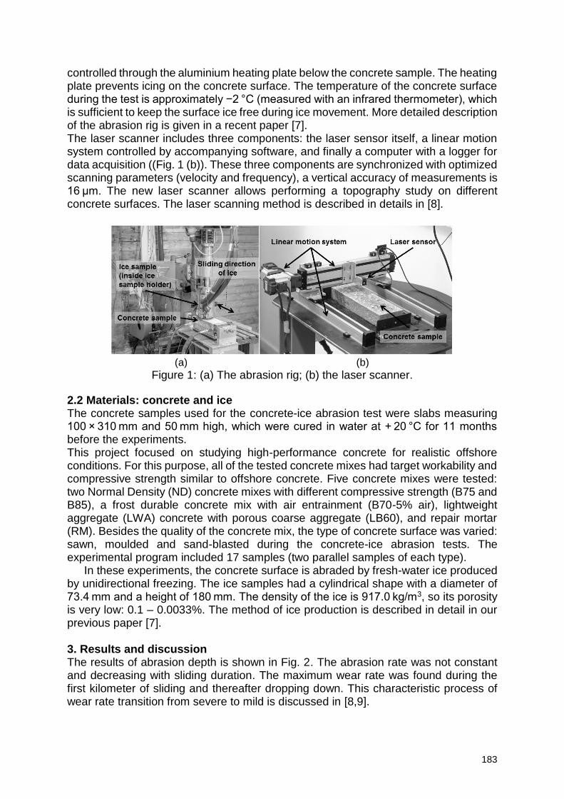
183
controlled through the aluminium heating plate below the concrete sample. The heating plate prevents icing on the concrete surface. The temperature of the concrete surface during the test is approximately −2 °C (measured with an infrared thermometer), which is sufficient to keep the surface ice free during ice movement. More detailed description of the abrasion rig is given in a recent paper [7]. The laser scanner includes three components: the laser sensor itself, a linear motion system controlled by accompanying software, and finally a computer with a logger for data acquisition ((Fig. 1 (b)). These three components are synchronized with optimized scanning parameters (velocity and frequency), a vertical accuracy of measurements is 16 μm. The new laser scanner allows performing a topography study on different concrete surfaces. The laser scanning method is described in details in [8].
(a) (b)
Figure 1: (a) The abrasion rig; (b) the laser scanner.
2.2 Materials: concrete and ice The concrete samples used for the concrete-ice abrasion test were slabs measuring 100 × 310 mm and 50 mm high, which were cured in water at + 20 °C for 11 months before the experiments. This project focused on studying high-performance concrete for realistic offshore conditions. For this purpose, all of the tested concrete mixes had target workability and compressive strength similar to offshore concrete. Five concrete mixes were tested: two Normal Density (ND) concrete mixes with different compressive strength (B75 and B85), a frost durable concrete mix with air entrainment (B70-5% air), lightweight aggregate (LWA) concrete with porous coarse aggregate (LB60), and repair mortar (RM). Besides the quality of the concrete mix, the type of concrete surface was varied: sawn, moulded and sand-blasted during the concrete-ice abrasion tests. The experimental program included 17 samples (two parallel samples of each type).
In these experiments, the concrete surface is abraded by fresh-water ice produced by unidirectional freezing. The ice samples had a cylindrical shape with a diameter of 73.4 mm and a height of 180 mm. The density of the ice is 917.0 kg/m3, so its porosity is very low: 0.1 – 0.0033%. The method of ice production is described in detail in our previous paper [7].
3. Results and discussion The results of abrasion depth is shown in Fig. 2. The abrasion rate was not constant and decreasing with sliding duration. The maximum wear rate was found during the first kilometer of sliding and thereafter dropping down. This characteristic process of wear rate transition from severe to mild is discussed in [8,9].
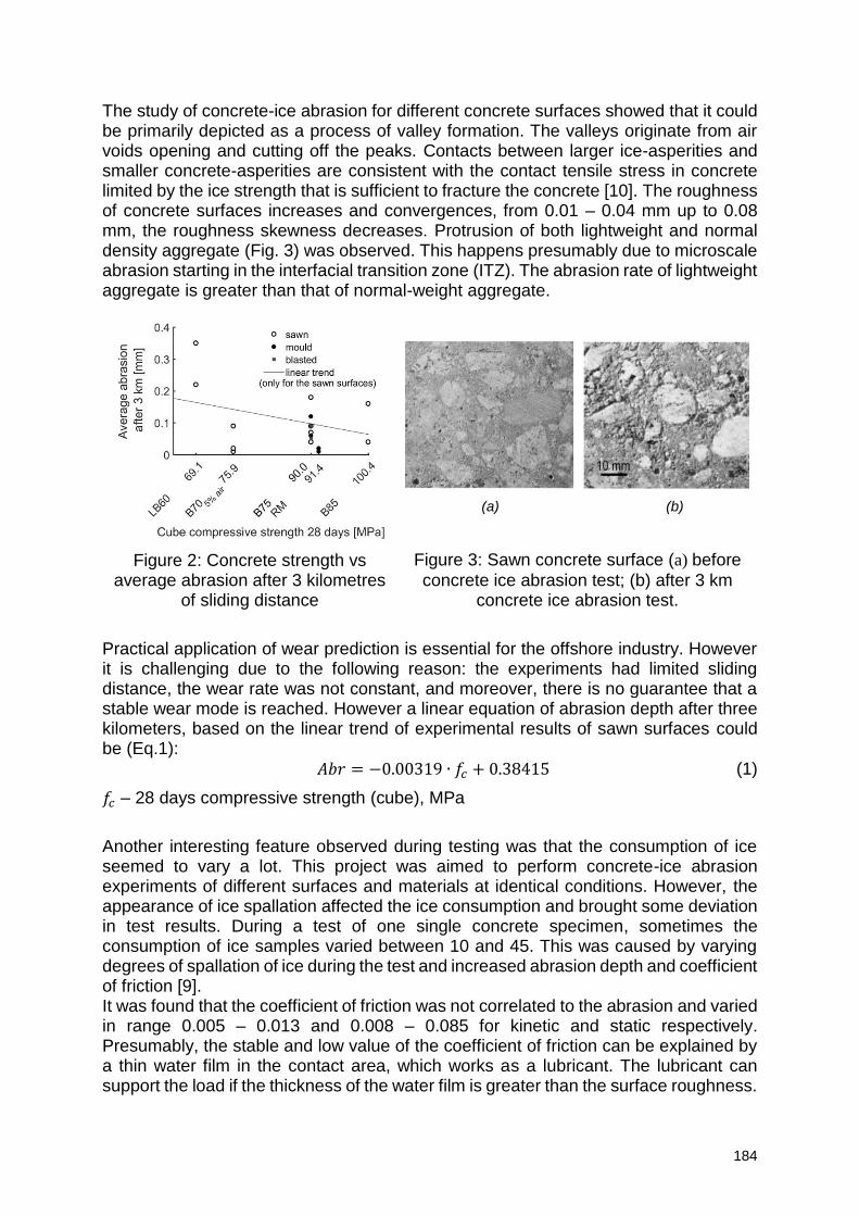
184
The study of concrete-ice abrasion for different concrete surfaces showed that it could be primarily depicted as a process of valley formation. The valleys originate from air voids opening and cutting off the peaks. Contacts between larger ice-asperities and smaller concrete-asperities are consistent with the contact tensile stress in concrete limited by the ice strength that is sufficient to fracture the concrete [10]. The roughness of concrete surfaces increases and convergences, from 0.01 – 0.04 mm up to 0.08 mm, the roughness skewness decreases. Protrusion of both lightweight and normal density aggregate (Fig. 3) was observed. This happens presumably due to microscale abrasion starting in the interfacial transition zone (ITZ). The abrasion rate of lightweight aggregate is greater than that of normal-weight aggregate.
(a) (b)
Figure 2: Concrete strength vs average abrasion after 3 kilometres
of sliding distance
Figure 3: Sawn concrete surface (a) before
concrete ice abrasion test; (b) after 3 km concrete ice abrasion test.
Practical application of wear prediction is essential for the offshore industry. However it is challenging due to the following reason: the experiments had limited sliding distance, the wear rate was not constant, and moreover, there is no guarantee that a stable wear mode is reached. However a linear equation of abrasion depth after three kilometers, based on the linear trend of experimental results of sawn surfaces could be (Eq.1):
𝐴𝑏𝑟 = −0.00319 ∙ 𝑓𝑐 + 0.38415 (1)
𝑓𝑐 – 28 days compressive strength (cube), MPa
Another interesting feature observed during testing was that the consumption of ice seemed to vary a lot. This project was aimed to perform concrete-ice abrasion experiments of different surfaces and materials at identical conditions. However, the appearance of ice spallation affected the ice consumption and brought some deviation in test results. During a test of one single concrete specimen, sometimes the consumption of ice samples varied between 10 and 45. This was caused by varying degrees of spallation of ice during the test and increased abrasion depth and coefficient of friction [9]. It was found that the coefficient of friction was not correlated to the abrasion and varied in range 0.005 – 0.013 and 0.008 – 0.085 for kinetic and static respectively. Presumably, the stable and low value of the coefficient of friction can be explained by a thin water film in the contact area, which works as a lubricant. The lubricant can support the load if the thickness of the water film is greater than the surface roughness.
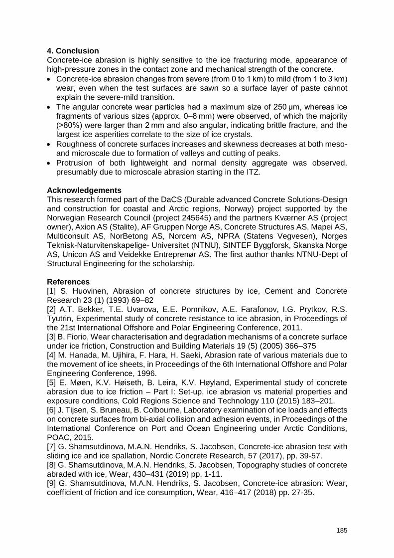
185
4. Conclusion Concrete-ice abrasion is highly sensitive to the ice fracturing mode, appearance of high-pressure zones in the contact zone and mechanical strength of the concrete.
Concrete-ice abrasion changes from severe (from 0 to 1 km) to mild (from 1 to 3 km) wear, even when the test surfaces are sawn so a surface layer of paste cannot explain the severe-mild transition.
The angular concrete wear particles had a maximum size of 250 μm, whereas ice fragments of various sizes (approx. 0–8 mm) were observed, of which the majority (>80%) were larger than 2 mm and also angular, indicating brittle fracture, and the largest ice asperities correlate to the size of ice crystals.
Roughness of concrete surfaces increases and skewness decreases at both meso- and microscale due to formation of valleys and cutting of peaks.
Protrusion of both lightweight and normal density aggregate was observed, presumably due to microscale abrasion starting in the ITZ.
Acknowledgements This research formed part of the DaCS (Durable advanced Concrete Solutions-Design and construction for coastal and Arctic regions, Norway) project supported by the Norwegian Research Council (project 245645) and the partners Kværner AS (project owner), Axion AS (Stalite), AF Gruppen Norge AS, Concrete Structures AS, Mapei AS, Multiconsult AS, NorBetong AS, Norcem AS, NPRA (Statens Vegvesen), Norges Teknisk-Naturvitenskapelige- Universitet (NTNU), SINTEF Byggforsk, Skanska Norge AS, Unicon AS and Veidekke Entreprenør AS. The first author thanks NTNU-Dept of Structural Engineering for the scholarship. References [1] S. Huovinen, Abrasion of concrete structures by ice, Cement and Concrete Research 23 (1) (1993) 69–82 [2] A.T. Bekker, T.E. Uvarova, E.E. Pomnikov, A.E. Farafonov, I.G. Prytkov, R.S. Tyutrin, Experimental study of concrete resistance to ice abrasion, in Proceedings of the 21st International Offshore and Polar Engineering Conference, 2011. [3] B. Fiorio, Wear characterisation and degradation mechanisms of a concrete surface under ice friction, Construction and Building Materials 19 (5) (2005) 366–375 [4] M. Hanada, M. Ujihira, F. Hara, H. Saeki, Abrasion rate of various materials due to the movement of ice sheets, in Proceedings of the 6th International Offshore and Polar Engineering Conference, 1996. [5] E. Møen, K.V. Høiseth, B. Leira, K.V. Høyland, Experimental study of concrete abrasion due to ice friction – Part I: Set-up, ice abrasion vs material properties and exposure conditions, Cold Regions Science and Technology 110 (2015) 183–201. [6] J. Tijsen, S. Bruneau, B. Colbourne, Laboratory examination of ice loads and effects on concrete surfaces from bi-axial collision and adhesion events, in Proceedings of the International Conference on Port and Ocean Engineering under Arctic Conditions, POAC, 2015. [7] G. Shamsutdinova, M.A.N. Hendriks, S. Jacobsen, Concrete-ice abrasion test with sliding ice and ice spallation, Nordic Concrete Research, 57 (2017), pp. 39-57. [8] G. Shamsutdinova, M.A.N. Hendriks, S. Jacobsen, Topography studies of concrete abraded with ice, Wear, 430–431 (2019) pp. 1-11. [9] G. Shamsutdinova, M.A.N. Hendriks, S. Jacobsen, Concrete-ice abrasion: Wear, coefficient of friction and ice consumption, Wear, 416–417 (2018) pp. 27-35.
186
[10] Jacobsen S., Scherer G., Schulson E. Concrete-Ice Abrasion Mechanics, Cement and Concrete Research, 73 (2015) 79-95
187
Frost testing of HP/HVFA concrete for severe offshore conditions
A. Shpak1, K.T. Fosså2, S. Jacobsen1
1 Norwegian University of Science and Technology, NTNU, Richard Birkelands vei 1a, NO-7034 Trondheim, Norway – [email protected]; [email protected] 2 Kvaerner AS, Concrete Solutions, Hinna Brygge, Bygg 1, Jåttåvågen, 4020 Stavanger, Norway – [email protected]
Abstract In the Durable Advanced Concrete Solution (DACS) project lead by Kvaerner and supported by a group of Norwegian concrete industries and The Norwegian Research Council the production and documentation of frost durable concrete for arctic and subarctic marine conditions is studied. The area encompasses frost exposure conditions and national standards relevant for the Arctic region. A series of HP/HVFA concretes were therefore subjected to various severe freeze-thaw tests of degradation due to internal cracking and surface scaling. Two of the most used methods, ASTM C666, procedure A for rapid freeze-thaw in water and CEN/TS 12390 for surface scaling in presence of 3 % NaCl solution, were used and extended to investigate how cracking, scaling and saturation progress at standard (-20 C) and very low (-50 C) temperatures in such severe conditions. This paper presents some preliminary results made to proceed in the understanding of how internal frost damage and surface scaling occur in rapid freeze-thaw testing in water (by far the most common way of frost testing concrete), how this relates to water uptake during curing and during subsequent freeze-thaw and the effect of air entrainment in this kind of frost testing. Keywords: Frost resistance, Fly ash, Air voids, Arctic Exposure, Freshwater scaling 1. Introduction Concrete has proven to be the only material used in large offshore structures in subarctic exposure that could withstand severe freeze-thaw and ice loads and maintain longevity, f.ex. Hibernia (CA), Sakhalin-I (RU), Hebron (CA) offshore gravity base structures, Confederation Bridge (CA), Øresund bridge (SWE/DK). Concrete was again chosen for a 120m tall semi-submersible foundation of White Rose platform that is being built in NF, CA [http://westwhiteroseproject.ca/]. With the increasing demand for low-carbon binders, there is also an increasing need for technology on how to produce frost-resistant low-carbon concrete for these kinds of severe conditions. Fly ash concrete has to a certain extent been found capable to withstand severe freeze-thaw cycles: with moderate Fly ash dosage, when properly air-entrained and cured [1], but for high fly-ash replacement and little curing frost durability can be a problem [2]. Rapid freeze-thaw testing in water has been observed to cause surface scaling from concrete (even in the absence of deicing salt) and the internal damage has been found to relate to the accelerated uptake of water during freeze-thaw [3]. Furthermore, the accelerated water uptake in ASTM C666 procedure A testing [4] has been found to continue during cycling and to correlate to internal cracking [5]. The specimens of ASTM C666 are cured in water continuously until the start of freeze-thaw and, in this period, there is an initial (isothermal) water uptake that is caused by self-desiccation and possibly some air-void filling. This paper presents some new findings in this field.
188
2. Experiments and materials All concrete mixes were exposed to ASTM C666 Proc A testing with simultaneous measurements of RDM (Relative Dynamic E-Modulus), scaling and weight increase due to water absorption. The compensation of loss of evaporable water in the scaled mass was done by multiplying dried scaled mass with the evaporable water content of concrete measured by the PF-testing and corrected for the paste fraction at the surface. Table 1 shows a few key mix design results, air-void system, water uptake in curing and compressive strengths. The mix code refers to w/b-ratio, FA/b-ratio and the air-entrainment, i.e. 0.40-35 A means w/b=0.40, FA/b = 0.35 and air-entrained (0.40-35 0 is a code for non-air-entrained mix). All mixes contain 4% of SF in a binder, and they were produced with the slump variation 190 - 220 mm. The w/b = 0.293 mixes were made to represent w/c = 0.45 for zero pozzolan hydration, i.e. as a “rival” to 0.45-0 A. As we see, most entrained air-void systems were very effective in terms of both air-void spacing [4] and Pore Protection Factors [6]. The absorption during curing is low for the fly ash concrete compared to previous measurements on OPC and OPC+SF concrete [7]. The absorption during curing, similar strength and the air content of 0.293-35 A and 0.45-0 A indicate that Fly Ash (FA) did not contribute to hydration the first 14-28 days. Analyses of hydration with other methods are underway. Furthermore, the levels of absorption in Fly Ash concrete are low compared to previous experiences with this simple method on OPC specimens. It should also be mentioned that air voids do not increase the absorption as marked in FA- as in OPC- a silica fume concretes.
Table 1: Properties of fresh and hardened concrete.
Mix Paste
volume [L]
Air content,
fresh1
[%]
Air content,
hardened2
[%]
Spacing
factor2
[mm]
PF [%]
Absorption during curing [vol% paste] Compressive
strength [MPa]
ASTM cylinder
Cubes3
100 mm
14d4 28d 91d 1y 28d 91d 1y
0.40-35 A 265 5,6 4,7 0,24 30,2 6,8 7,4 8,5 59,3 71,6 81,2
0.40-35 0 263 1,2 2,8 0,79 16,0 6,1 7,2 7,8 73,2 90,2 101,9
0.45-35 A 266 5,8 4,1 0,18 32,5 5,9 7,0 50,4 63,3
0.45-35 0 263 1,3 2,0 0,68 17,0 6,5 7,0 67 81,9
0.293-35 A 266 5,9 5,9 0,20 36,1 5,3 5,6 6,2 81,5 93
0.293-35 0 262 2,0 1,8 0,63 17,6 5,1 6,0 6,8 98,8 114,9
0.45-0 A 270 5,1 6,2 0,30 31,7 6,2 6,9 8,3 77,2
1 Density method 2 Acc. to Fonseca et al. and ASTM C457, scanning - 3200ppi 3 Measured on cubes 100 x 100 x 100 mm3 4 Beginning of ASTM C666 testing, measured on cores 300 mm D~95-100mm
3. Results and discussion Figure 1 shows internal damage and surface scaling during freeze-thaw cycling. From the results, it is clear that a proper air-void system with L ≤ 0.24 mm protects the fly ash concrete whereas the OPC mix 0.45-0 A with L = 0.30 mm suffers internal damage. However, we could also clearly see that the drop in RDM is accompanied by a sudden increase in the scaling rate. From that case, for “bad concrete”, internal cracking and scaling could possibly be interrelated. For stronger concretes with low water-to-binder ratio (0,293-35) or well-cured fly ash concretes (0.40-35 water-cured for 1 year) the cracking and scaling results do not complement one another.
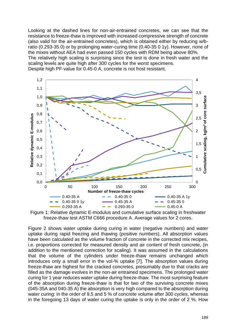
189
Looking at the dashed lines for non-air-entrained concretes, we can see that the resistance to freeze-thaw is improved with increased compressive strength of concrete (also valid for the air-entrained concretes), which is obtained either by reducing w/b-ratio (0.293-35 0) or by prolonging water-curing time (0.40-35 0 1y). However, none of the mixes without AEA had even passed 150 cycles with RDM being above 80%. The relatively high scaling is surprising since the test is done in fresh water and the scaling levels are quite high after 300 cycles for the worst specimens. Despite high PF-value for 0.45-0 A, concrete is not frost resistant.
Figure 1: Relative dynamic E-modulus and cumulative surface scaling in freshwater
freeze-thaw test ASTM C666 procedure A. Average values for 2 cores.
Figure 2 shows water uptake during curing in water (negative numbers) and water uptake during rapid freezing and thawing (positive numbers). All absorption values have been calculated as the volume fraction of concrete in the corrected mix recipes, i.e. proportions corrected for measured density and air content of fresh concrete, (in addition to the mentioned correction for scaling). It was assumed in the calculations that the volume of the cylinders under freeze-thaw remains unchanged which introduces only a small error in the vol-% uptake [7]. The absorption values during freeze-thaw are highest for the cracked concretes, presumably due to that cracks are filled as the damage evolves in the non-air entrained specimens. The prolonged water curing for 1 year reduces water uptake during freeze-thaw. The most surprising feature of the absorption during freeze-thaw is that for two of the surviving concrete mixes (045-35A and 040-35 A) the absorption is very high compared to the absorption during water curing: in the order of 9,5 and 5 % of concrete volume after 300 cycles, whereas in the foregoing 13 days of water curing the uptake is only in the order of 2 %. How
0
0,5
1
1,5
2
2,5
3
3,5
4
0,0
0,1
0,2
0,3
0,4
0,5
0,6
0,7
0,8
0,9
1,0
1,1
1,2
0 50 100 150 200 250 300
Cu
mu
lati
ve s
calin
g,
kg
/m2 o
f co
re s
urf
ace
Rela
tiv
e d
yn
am
ic E
-mo
du
lus
Number of freeze-thaw cycles
0.40-35 A 0.40-35 0 0.40-35 A 1y
0.40-35 0 1y 0.45-35 A 0.45-35 0
0.293-35 A 0.293-35 0 0.45-0 A
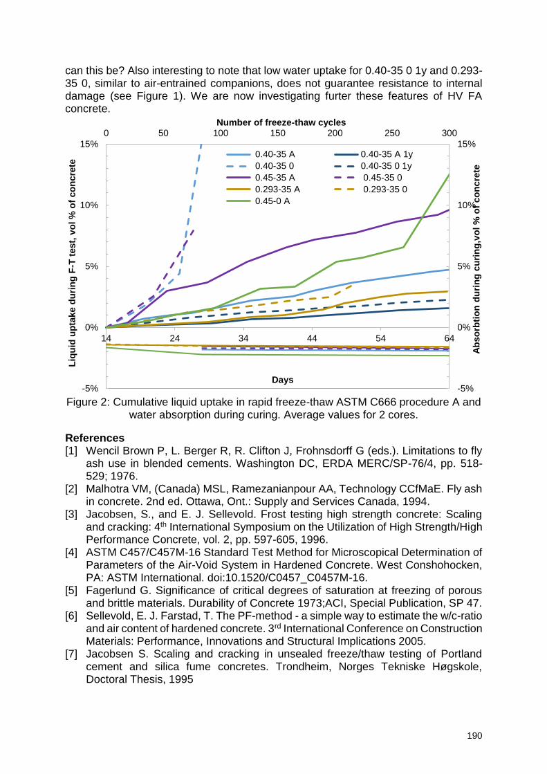
190
can this be? Also interesting to note that low water uptake for 0.40-35 0 1y and 0.293-35 0, similar to air-entrained companions, does not guarantee resistance to internal damage (see Figure 1). We are now investigating furter these features of HV FA concrete.
Figure 2: Cumulative liquid uptake in rapid freeze-thaw ASTM C666 procedure A and
water absorption during curing. Average values for 2 cores.
References
[1] Wencil Brown P, L. Berger R, R. Clifton J, Frohnsdorff G (eds.). Limitations to fly ash use in blended cements. Washington DC, ERDA MERC/SP-76/4, pp. 518-529; 1976.
[2] Malhotra VM, (Canada) MSL, Ramezanianpour AA, Technology CCfMaE. Fly ash in concrete. 2nd ed. Ottawa, Ont.: Supply and Services Canada, 1994.
[3] Jacobsen, S., and E. J. Sellevold. Frost testing high strength concrete: Scaling and cracking: 4th International Symposium on the Utilization of High Strength/High Performance Concrete, vol. 2, pp. 597-605, 1996.
[4] ASTM C457/C457M-16 Standard Test Method for Microscopical Determination of Parameters of the Air-Void System in Hardened Concrete. West Conshohocken, PA: ASTM International. doi:10.1520/C0457_C0457M-16.
[5] Fagerlund G. Significance of critical degrees of saturation at freezing of porous and brittle materials. Durability of Concrete 1973;ACI, Special Publication, SP 47.
[6] Sellevold, E. J. Farstad, T. The PF-method - a simple way to estimate the w/c-ratio and air content of hardened concrete. 3rd International Conference on Construction Materials: Performance, Innovations and Structural Implications 2005.
[7] Jacobsen S. Scaling and cracking in unsealed freeze/thaw testing of Portland cement and silica fume concretes. Trondheim, Norges Tekniske Høgskole, Doctoral Thesis, 1995
14 24 34 44 54 64
-5%
0%
5%
10%
15%
-5%
0%
5%
10%
15%
0 50 100 150 200 250 300
Days
Ab
so
rbti
on
du
rin
g c
uri
ng
,vo
l %
of
co
ncre
te
Liq
uid
up
take d
uri
ng
F-T
test,
vo
l %
of
co
ncre
te
Number of freeze-thaw cycles
0.40-35 A 0.40-35 A 1y
0.40-35 0 0.40-35 0 1y
0.45-35 A 0.45-35 0
0.293-35 A 0.293-35 0
0.45-0 A
191
Durable concrete for infrastructure with high performance binders
T. Deuse, S. Irico, D. Qvaeschning
Wilhelm Dyckerhoff Institute for Building Materials Technology, Dyckerhoff GmbH, Dyckerhoffstraße 7, 65203 Wiesbaden, Germany – [email protected]; [email protected]; [email protected]
Abstract Modern cement technology and the use of ultrafine components allow the composition and optimization of advanced high performance binders at the cement plant. The outstanding mineralogical and granulometric characteristics of these binders result in excellent properties of the fresh and hardened concrete which forms particularly dense and homogenous concrete structures. The dense matrix of reactive components prevents aggressive or attacking substances penetrating into the structure and increases the durability respectively. The best available technology of high performance binders is based on the combination of high-quality standard cements and ultrafine cements or supplementary materials enabling a specific adjustment of properties by granulometric optimization. In the framework of the ongoing European collaborative project LORCENIS modern high performance binders, based on Dyckerhoff Mikrodur® technology, were used to develop durable concretes to withstand severe operating conditions. The concretes are characterized by their mechanical properties. Investigations on durability were performed at lab scale by means of pore size distribution measurements using mercury intrusion porosimetry, chloride migration tests according to German BAW code of practice and freeze thaw resistance tests (CDF) according to the RILEM Recommendations TC 117-FDC. Accelerated acid resistance tests were performed with sulfuric acid at a constant pH-value of 2 according to the pH-stat method. The results of the durability tests on SCC samples produced with different binder compositions confirm the excellent resistance against severe operating conditions e. g. chloride ingress, freeze thaw or acid attack. The best performance was obtained by replacing 30 to 40 % of OPC with Mikrodur® based on ultrafine ground blast furnace slag. Additionally this replacement of ordinary Portland cement with supplementary cementitious materials contributes to the reduction of the carbon footprint. The high durability of the materials will increase the service life of the structures and reduce maintenance and life cycle costs. Keywords: high performance binders, ultrafine cements, durability, acid resistance 1. Introduction In modern cement technology the use of ultrafine binder components and advanced superplasticizers allows for the composition of optimized cements for high-performance concrete. The outstanding mineralogical and granulometric characteristics of these binders result in excellent properties of both the fresh and hardened concrete which forms a particularly dense, homogenous concrete matrix. The high density produced by the reactive components prevents aggressive or
192
attacking substances penetrating into the concrete and increases the durability respectively. The best available technology of high performance binders is based on the combination of high-quality standard cements with ultrafine cements or supplementary cementitious materials enabling the adjustment of properties through granulometric optimization. 2. Materials In the framework of the ongoing European collaborative project LORCENIS modern high performance binders, based on Dyckerhoff Mikrodur® technology, were used to develop durable concretes to withstand severe operating conditions. The proven technology builds upon an advanced grinding and classification process for cements or supplementary cementitious materials (SCMs) respectively. A similar process is described in [1]. The resulting Mikrodur® particles have a particle size (d95) of 6 to 20 µm and a specific surface area of more than 10,000 Blaine. They are usually combined with high quality standard cements to improve the properties of the binders by enhancing the particle size distribution and the dense packing of particles in the concrete matrix. Regarding the specific requirements of the durability of concretes exposed to severe environmental conditions, the test programme was extended by a high sulfate resistant (HSR) cement and a belite-rich Portland (HBC) cement which is also known for its improved sulfate resistance due to a lower content of C3A and less portlandite, formed by the hydration process [2].
Table 1: Characterization of the used binders. Basic binders Type Specific property Blaine Remarks
CEM I 52,5 R OPC -- 5,500 cm²/g High quality OPC CEM I 42,5 SR 0/NA HSR C3A = 0 % 4,000 cm²/g High sulfate resistance CEM I 42,5 L HBC C2S ≥ 75 % 4,750 cm²/g Belite-rich PC
3. Sample preparation and test methods According to the principles of LORCENIS an advanced concrete in the form of a self-compacting concrete (SCC) was adapted to meet the requirements of the requested scenario (Exposure class XA3 [3]). An additional improvement of the performance of the concrete was achieved by the addition of ultrafine cement in order to obtain a dense homogenous structure. The ultrafine cement (Mikrodur® R-U) used was based on GBFS and had a particle size of d95 < 20 µm.
Table 2: Binder composition for 6 self-compacting mix designs [kg/m³]. No. Mix design Binder type Cement Mikrodur® R-U Class F Fly Ash
1 OPC 420 -- 100 2 Pristine HSR 420 -- 100 3 HBC 420 -- 100
4 OPC/R-U 275 145 100 5 Mikrodur® HSR/R-U 275 145 100 6 HBC/R-U 275 145 100
The concrete was mixed in a rotating pan mixer with a w/c ratio of 0.36 and an aggregate to cement ratio of 4. The aggregates used were sand and gravel in the fraction of 0/16 mm. A PCE based superplasticizer was used to adjust and maintain the consistency of the SCC.
193
Table 3: Consistency of the fresh concretes (SCC).
No. Mix design Binder type Slump start [mm] Slump 30’ [mm] Air [Vol.-%]
1 OPC 755 700 1.6 2 Pristine HSR 705 725 1.4 3 HBC 780 760 0,9
4 OPC/R-U 765 690 1.2 5 Mikrodur® HSR/R-U 710 735 0.9 6 HBC/R-U 710 760 1.4
The concretes were characterized by their mechanical properties.
Table 4: Compressive strength of the hardened concretes. No. Mix design Binder Type fcm,7d [MPa] fcm,28d [MPa] fcm,56d [MPa]
1 OPC 69 87 94 2 Pristine HSR 61 82 82 3 HBC 28 65 80 / 91*
4 OPC/R-U 74 93 94 5 Mikrodur® HSR/R-U 72 96 101 6 HBC/R-U 56 66 74
*after 90 days of curing
Investigations on durability were performed on a lab scale by means of pore size distribution measurements using mercury intrusion porosimetry, chloride migration tests according to the German BAW code of practice and freeze thaw resistance tests (CDF) according to the RILEM Recommendations TC 117-FDC. Accelerated acid resistance tests were performed with sulfuric acid at a constant pH-value of 2 according to the pH-stat method [4]. 4. Results and discussion The results of the Hg-porosimetry measurements of the samples demonstrated a general reduction of the total porosity by 0.5 to 2 vol% due to the addition of the ultrafine cement. The greatest effect was recorded with the HSR cement showing the lowest fineness of the pristine system. The observed reduction of porosity correlates with the results of the chloride migration tests. The migration coefficient of all samples was significantly improved by the addition of the ultrafine cement. It lies significantly below the threshold of 5 · 10-12 m²/s set by the German BAW code [5] for exposure class XS3, XD3. In addition the freeze thaw resistance tests show that after 28 cycles of exposure the positive influence of the addition of Mikrodur® caused by the dense structure of the samples. A reduction of the total scaling up to 60 % was observed on the example of the HSR binder which failed the test without additional measures. After the addition of the ultrafine cement the scaling fell far below the threshold of 1,500 g/m² set by the RILEM Recommendations TC 117-FDC [6].
The accelerated acid resistance tests revealed the more or less strong effect of the addition of ultrafine cement on acid resistance (Figure 1). The mineral compositions of the binders and their hydration products have a more distinct influence on the acid resistance. Especially the HBC system, which forms less portlandite during the hydration process, showed an extraordinarily high resistance to attack from sulfuric acid.
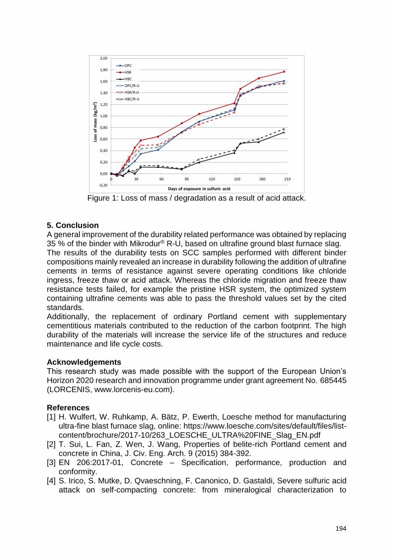
194
Figure 1: Loss of mass / degradation as a result of acid attack.
5. Conclusion A general improvement of the durability related performance was obtained by replacing 35 % of the binder with Mikrodur® R-U, based on ultrafine ground blast furnace slag. The results of the durability tests on SCC samples performed with different binder compositions mainly revealed an increase in durability following the addition of ultrafine cements in terms of resistance against severe operating conditions like chloride ingress, freeze thaw or acid attack. Whereas the chloride migration and freeze thaw resistance tests failed, for example the pristine HSR system, the optimized system containing ultrafine cements was able to pass the threshold values set by the cited standards. Additionally, the replacement of ordinary Portland cement with supplementary cementitious materials contributed to the reduction of the carbon footprint. The high durability of the materials will increase the service life of the structures and reduce maintenance and life cycle costs. Acknowledgements This research study was made possible with the support of the European Union’s Horizon 2020 research and innovation programme under grant agreement No. 685445 (LORCENIS, www.lorcenis-eu.com). References [1] H. Wulfert, W. Ruhkamp, A. Bätz, P. Ewerth, Loesche method for manufacturing
ultra-fine blast furnace slag, online: https://www.loesche.com/sites/default/files/list-content/brochure/2017-10/263_LOESCHE_ULTRA%20FINE_Slag_EN.pdf
[2] T. Sui, L. Fan, Z. Wen, J. Wang, Properties of belite-rich Portland cement and concrete in China, J. Civ. Eng. Arch. 9 (2015) 384-392.
[3] EN 206:2017-01, Concrete – Specification, performance, production and conformity.
[4] S. Irico, S. Mutke, D. Qvaeschning, F. Canonico, D. Gastaldi, Severe sulfuric acid attack on self-compacting concrete: from mineralogical characterization to
-0,20
0,00
0,20
0,40
0,60
0,80
1,00
1,20
1,40
1,60
1,80
2,00
0 30 60 90 120 150 180 210
Loss
of
mas
s (k
g/m
²)
Days of exposure in sulfuric acid
OPC
HSR
HBC
OPC/R-U
HSR/R-U
HBC/R-U
195
durability properties, Proceedings of the Conference on Durable Concrete for Infrastructure under Severe Conditions, Ghent, 2019.
[5] BAW Merkblatt Chlorideindringwiderstand von Beton (MCL) (Code of practice chloride penetration resistance of concrete, Federal Waterways Engineering and resarch Institute), Issue 2012.
[6] RILEM Recommendation TC 117-FDC, CDF test – test method for the freeze thaw and deicing resistance of concrete – Tests with sodium chloride (CDF), RILEM Publications SARL, 1996.
196
Local electrochemical characterization – A novel approach to study initiation of chloride induced corrosion in reinforced concrete
structure
L. Michel1, M. Stefanoni1, U. Angst1
1 Department of Civil, Environmental and Geomatic Engineering, Institute for Building Materials (IfB), ETH Hönggerberg, CH-8093 Zürich, Switzerland – [email protected]; [email protected]
Abstract Corrosion due to the presence of chloride is the most common degradation mechanism of reinforced concrete infrastructures. In marine environments, ageing of existing and building of new structures in energy sector will increase the impact of this mechanism. The spatial separation of active and passive zones, characteristic for this process, can lead to a fast and dangerous local degradation of the reinforcing steel. A more accurate understanding of the corrosion mechanism, especially its initiation, is thus important to predict and mitigate its deleterious effects on our reinforced concrete infrastructures.
The majority of the research on chloride-induced corrosion in concrete implicitly considers the reinforcing steel as a uniform material in terms of its corrosion properties. This contrasts with the localized character of the chloride-induced corrosion. In the present work, we propose a novel technique to locally characterize reinforcing steel samples in terms of electrochemical behavior.
Reinforcing steel bars with different metallurgy, obtained through heat treatment, were analyzed. Using the presented technique, local electrochemical characterization was performed. The obtained electrochemical values are discussed with respect to future research towards finally understanding corrosion initiation in chloride contaminated concrete. 1. Introduction Many infrastructures in the energy sector are built with concrete and some are reinforced, e.g. Condeep gravity based offshore platforms [1]. Their main cause of degradation is the corrosion of steel reinforcement [2]. Two main mechanisms can lead to corrosion in concrete, carbonation and chloride-induced corrosion. This paper focuses on the latter mechanism. A chloride-containing environment, e.g. marine, can significantly reduce the service life of reinforced concrete (RC) structures. Fortunately, the energy sector is already aware of this problem and corrosion prevention measure are commonly used [3]. Despite this, condition assessment of existing structures is a concern for the energy sector. Furthermore, the limitation of corrosion in future infrastructures is also a challenge, as more and more RC structures will be built offshore due to scarcity of traditional reserve of fossil fuel resources and development of offshore sustainable energy [1]. A good management of corrosion will reduce maintenance costs, reduce risks of failures, and increase the service life of these infrastructures. Unfortunately, the chloride induced corrosion mechanism is not fully understood. A clear link has been established in the 1960s between initiation of corrosion and the presence of chloride ions in the vicinity of the steel [4]. Many research efforts were dedicated to identification of a chloride threshold concentration [5]. It appears from the literature that this threshold value scatters over a wide range and offers no useful basis to determine the occurrence of corrosion initiation [5]. The concept of initiation of
197
corrosion only based on chloride concentration is limited and it needs to be expanded by the determination of the other(s) relevant parameter(s). The Steel-Concrete Interface and all its inhomogeneities is now the subject of several projects [6]. Some authors consider the steel as a homogeneous material, with for example a homogeneous Open Circuit Potential (OCP) value across the considered steel surface (given homogeneous exposure conditions). Others have raised the question of the influence of possible differences at the surface of one steel sample on the initiation of localized corrosion [7, 8]. Heat treatment of steel is known to modify the microstructure, the distribution of grains and the internal stresses [9]. This work is focused on the surface steel inhomogeneities, characterized in term of local electrochemical characteristics. Two steel samples were tested, one “as received” and one “annealed”. 2. Materials and methods 2.1 Materials Two different types of plain carbon steel reinforcement bars, each with a diameter of 12 mm, were tested in this study. The rebars were supplied by a local steel producer. The metallography of the steel was analyzed in a previous work, the tested samples correspond to series D in [10]. One series was tested “as received”. No visible signs of rust were present on the steel surface. The other series (termed “annealed”) consisted of the same rebar type, but we subjected it to a heat treatment, consisting of heating of the steel above 900°C for 3 hours in a furnace, followed by cooling inside the furnace until it reached room temperature. The thick scale formed during the heat treatment was flaking, and was removed by light hammering prior to the electrochemical tests. Due to the heat treatment, the “annealed” steel microstructure was assumed to be ferrite-pearlite [9]. Also here, no visible signs of rust were present on the steel surface.
Table 1: Designation, degree of rust, surface treatment, and microstructure of the surface-near zone of the tested materials.
Designation Rust degree Surface Treatment Surface Microstructure
As received Low As received Martensite Annealed Low Annealed + scale removed Ferrite-pearlite
2.2 Local electrochemical measurements The local electrochemical sensor was already presented in several publications [9, 11]. To summarize, it consists of a reference electrode and a container for the test electrolyte as well as a small sponge-like tip through which contact to the steel surface can be established. The test electrolyte consisted of a solution of 0.1M of NaOH and 0.01M NaCl, pH=13. The contact area between the tested samples and the local electrochemical sensor was kept as constant as possible around a value of 1 mm2. With help of the internal reference electrode, it was possible to measure the open circuit potential of the steel surface, locally, i.e. of the steel surface in contact with the test electrolyte. All experiments were performed at room temperature ≈ 20 (± 2) °C. The local OCP values were measured on the surface of the steel reinforcing bars following a grid of 2 mm spacing between two measurements on the longitudinal direction and around the circumference of the rebars.
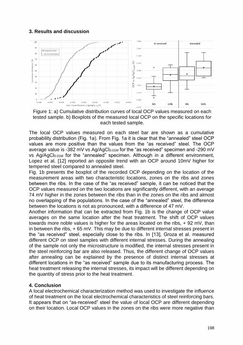
198
3. Results and discussion
The local OCP values measured on each steel bar are shown as a cumulative probability distribution (Fig. 1a). From Fig. 1a it is clear that the “annealed” steel OCP values are more positive than the values from the “as received” steel. The OCP average value is -382 mV vs Ag/AgCl0.01M for the “as received” specimen and -290 mV vs Ag/AgCl0.01M for the “annealed” specimen. Although in a different environment, Lopez et al. [12] reported an opposite trend with an OCP around 10mV higher for tempered steel compared to annealed steel. Fig. 1b presents the boxplot of the recorded OCP depending on the location of the measurement areas with two characteristic locations, zones on the ribs and zones between the ribs. In the case of the “as received” sample, it can be noticed that the OCP values measured on the two locations are significantly different, with an average 74 mV higher in the zones between the ribs than in the zones on the ribs and almost no overlapping of the populations. In the case of the “annealed” steel, the difference between the locations is not as pronounced, with a difference of 47 mV. Another information that can be extracted from Fig. 1b is the change of OCP value averages on the same location after the heat treatment. The shift of OCP values towards more noble values is higher for the areas located on the ribs, + 92 mV, than in between the ribs, + 65 mV. This may be due to different internal stresses present in the “as received” steel, especially close to the ribs. In [13], Groza et al. measured different OCP on steel samples with different internal stresses. During the annealing of the sample not only the microstructure is modified, the internal stresses present in the steel reinforcing bar are also released. Thus, the different change of OCP values after annealing can be explained by the presence of distinct internal stresses at different locations in the “as received” sample due to its manufacturing process. The heat treatment releasing the internal stresses, its impact will be different depending on the quantity of stress prior to the heat treatment. 4. Conclusion A local electrochemical characterization method was used to investigate the influence of heat treatment on the local electrochemical characteristics of steel reinforcing bars. It appears that on “as-received” steel the value of local OCP are different depending on their location. Local OCP values in the zones on the ribs were more negative than
Figure 1: a) Cumulative distribution curves of local OCP values measured on each tested sample. b) Boxplots of the measured local OCP on the specific locations for
each tested sample.
199
in zones between the ribs. It also appears that the heat treatment of steel modified the general electrochemical state of the steel by a shift towards more positive values of local OCP. But also the inhomogeneity of the local OCP was modified. A smaller local OCP difference was measured between the zones on the ribs and the zones between the ribs after heat treatment. The impact of the heat treatment was also more important in the zones on the ribs than in the zones between the ribs. These preliminary tests showed the impact of heat treatment on local electrochemical inhomogeneities. To perform those tests on a more representative scale, automation of the local electrochemical measurements has been developed. This will allow us to characterize a large amount of specimens. The local electrochemical characterization method will be combined with corrosion initiation tests to see if correlation(s) can be established between the local electrochemical features and the corrosion initiation pattern in the case of localized corrosion. References [1] M. D. Esteban, J. S. López-Gutiérrez, V. Negro, Gravity-Based Foundations in the Offshore Wind Sector, Journal of Marine Science and Engineering 7.3 (2019) 64.
[2] C. Gehlen, et al. Condition Control and Assessment of Reinforced Concrete Structures Exposed to Corrosive Environments (Carbonation/Chlorides), Technical Report for International Federation of Structural Concrete (FIB): Lausanne, Switzerland, fib bulletin 59 (2011). [3] B. Heuze, Cathodic protection on concrete offshore platforms, Materials Performance 19 (1980) 24-33. [4] D.A. Hausmann, Steel corrosion in concrete—How does it occur?, Materials protection, 6, (1967) 19-23. [5] U. Angst, et al., Critical chloride content in reinforced concrete—a review, Cement and concrete research 39 (2009) 1122-1138. [6] U. Angst, et al., The steel–concrete interface, Materials and Structures 50.2 (2017)
143. [7] M. Kosalla, M. Raupach, Chloride-Induced Depassivation of Steel in Concrete—Influence of Electrochemical Potential and Anodic Polarization Level, Service Life and
Durability of Reinforced Concrete Structures (2019) 107.
[8] L. Michel, U. Angst, Towards understanding corrosion initiation in concrete–Influence of local electrochemical properties of reinforcing steel, MATEC Web of
Conferences 199 (2018). [9] T. V. Shibaeva, et al., The effect of microstructure and non-metallic inclusions on corrosion behavior of low carbon steel in chloride containing solutions, Corrosion
Science 80 (2014) 299-308.
[10] U. Angst, B. Elsener, Forecasting chloride-induced reinforcement corrosion in concrete—effect of realistic reinforcement steel surface conditions, Proceedings of the Fourth International Conference on Concrete Repair, Rehabilitation and Retrofitting, Leipzig, 2015, p. 177. [11] M. Büchler, C.-H. Voûte, F. Stalder, A new locally resolving electrochemical sensor: application in research and development, Electrochemical Society proceeding 24 (2002) 436-441. [12] D. A. Lopez, S. N. Simison, S. R. De Sanchez, The influence of steel microstructure on CO2 corrosion. EIS studies on the inhibition efficiency of benzimidazole, Electrochimica Acta 48.7 (2003) 845-854.
200
[13] J. R. Groza, M. Eslamloo-Grami, R. Bandy, The effect of thermo-mechanical
treatment on the pitting corrosion of reinforcing carbon steel bars, Materials and
Corrosion 44.9 (1993) 359-366.
201
Durability properties and compressive strength of high volume slag and high volume slag-fly ash blended concretes containing nano
silica
A. Hosan1, F. Shaikh2 1 School of Civil and Mechanical Engineering, Curtin University, Bentley Campus, 6845 Perth, Australia – [email protected] 2 School of Civil and Mechanical Engineering, Curtin University, Bentley Campus, 6845 Perth, Australia – [email protected]
Abstract This paper reports the effect of nano silica on compressive strength, sorptivity, volume of permeable voids and rapid chloride permeability of concrete containing 78% slag and 67% slag-fly ash blend. Results showed that addition of 2% and 3% nano silica increased the compressive strengths of concrete containing 78% slag and concrete containing 67% slag-fly ash blend by 33% and 44%, respectively at 3 days and 36% and 16%, respectively at 28 days compared to concrete containing high volume slag and high volume slag-fly ash blend without nano silica. It is also found that nano silica inclusion reduced water sorptivity by 26% and 38% and volume of permeable voids by 14% and 23% for concrete containing 78% slag and 67% slag-fly ash blend, respectively compared to control mixes without nano silica after 28 days of wet curing. Moreover, about 91% and 82% reduction of chloride ion permeability is also observed in concrete containing 78% slag and concrete containing 67% slag-fly ash blend due to addition of nano silica than control OPC concrete after 28 days of curing. Keywords: High volume slag, nano silica, compressive strengths, durability properties, high volume slag-fly ash blend. 1. Introduction Ordinary Portland cement is commonly used as a binding materials of concrete and study projected that consumption of cement will rise approximately by 115-180% in 2020 compared to 1990s [1]. However, cement production is extremely energy intensive and one tonne cement production releases roughly 0.9 tonne of carbon di-oxide (CO2) into the atmosphere [2-4]. Moreover, it is also found that, cement production required huge amount of virgin materials and only cement production adds around 7% of global carbon di-oxide per year subsequently leads to the global warming which is a key concern among world leaders in last decades [5, 6]. Economic and environmental consideration leads to the use of number of industrial waste materials such as fly ash, blast furnace slag, metakaolin, silica fume etc. as a partial replacement of cement in concrete to produce an eco-friendly concrete and lower the cost of concrete production. Among several supplementary cementitious materials (SCM), blast furnace slag and fly ash have been broadly used by researcher in last few decades to replace cement in bulk volume to reduce carbon emission and further developments of mechanical and durability of concrete [7, 8]. Several researches have been conducted to replace cement in high volume by blast furnace slag, fly ash and their combination but found very low early strength, large scale of bleeding, significant drying shrinkage, and tendency for briskly progress carbonation [9-17]. A few other studies have also been investigated to improve those challenges by using silica fume and limestone filler in ternary and quaternary mixes of cement, blast furnace slags and
202
fly ash but unfortunately no significant improvement observed in high volume replaced concrete properties [18-22]. Recently, several researches showed that addition of small amount of nano silica (NS) can accelerate the early hydration of cement, act as a nucleation site to quicken the hydration process and accelerate the consumption of tricalcium silicate (C3S) and form calcium silicate hydrate (C-S-H) [23-25]. Moreover, a very few valuable studies have been conducted concerning the influence of nano silica on the mechanical properties and microstructure of high volume slag and fly ash composites [26-32]. However, cement replacement lies up to 50% in all previous studies even though there is a strong demand for the higher volume of replacement from the perspective of reduction of carbon footprint of concrete. In a very recent study,[33] it is reported that addition of 1-4% NS in 70%, 80% and 90% slag replaced cement paste can improve compressive strength by 9-24%, 11-29% and 17-41%, respectively than their control cement paste and maintain higher compressive strength than control cement paste in several mixes. It is also found that NS addition improves compressive strength of high volume slag-fly ash blended cement pastes significantly and produce denser microstructure than the cement paste without NS. This paper presents the effect of addition of NS on compressive strengths and durability properties of high volume slag (HVS) and high volume slag-fly ash (HVS-FA) blended concretes. 2. Materials, mixing and testing methods Ordinary Portland cement (OPC) and blast furnace slag (BFS) used in this study are collected from a local cement company. The class F fly ash was supplied by Eraring power station in NSW, Australia. Dry nano silica powder with average particle diameter of 25 nm was from Nanostructured and Amorphous Materials, Inc. USA. A naphthalene sulphonate based superplasticizer was used to improve the workability of concrete mixes. Mix proportions of all concrete mixes are shown in Table 1 in which water/binder ratio was kept constant 0.4 and superplasticizer was used to maintain workability when needed. All concretes were mixed in a pan mixer in which dry ingredients were mixed approximately for 5 minutes and then water was added and mixed again for 2-3 minutes. In case of HVS and HVS-FA concrete mixes containing NS, the dry NS powder was first mixed in partial water with superplasticizer and then dispersed ultrasonically by ultrasonic mixer with highest amplitude for an hour and remaining water added during concrete mixing. Standard cylinders (100mm x 200mm) were cast and demoulded after 24 hours. Cylinders specimens were cured in water at room temperature and then compressive strengths were measured at 3 and 28 days according to ASTM C873 standard with a loading rate of 0.33 MPa/s. For each age at least three specimens were tested and average value of three measurement is reported. For durability test such as sorptivity, average volume of permeable voids (AVPV) and rapid chloride permeability test (RCPT), a 50 mm length discs were cut from 100 mm diameter cylinder after 28 days of wet curing and then tests were performed according to ASTM C1585, ASTM C 642 and ASTM C 1202 standards, respectively. Sorptivity test was performed to determine the rate of water absorption by measuring the mass of concrete specimens regularly from 1 min to 6 hours and absorption (I) was calculated by change in mass divided by cross sectional area of the specimens and the density of water. Volume of permeable voids were conducted to determine the voids present in the concrete specimens and is measured by boiling the 50mm cut concrete discs at 105⁰C for at least 5 hours and then weighing the samples
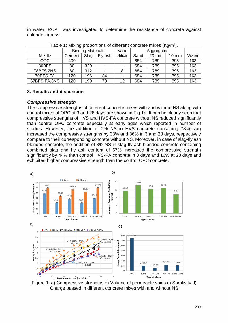
203
in water. RCPT was investigated to determine the resistance of concrete against chloride ingress.
Table 1: Mixing proportions of different concrete mixes (Kg/m3).
Mix ID Binding Materials Nano
Silica Aggregates
Water Cement Slag Fly ash Sand 20 mm 10 mm
OPC 400 - - - 684 789 395 163
80BFS 80 320 - - 684 789 395 163
78BFS.2NS 80 312 - 8 684 789 395 163
70BFS-FA 120 196 84 - 684 789 395 163
67BFS-FA.3NS 120 190 78 12 684 789 395 163
3. Results and discussion Compressive strength The compressive strengths of different concrete mixes with and without NS along with control mixes of OPC at 3 and 28 days are shown in Fig.1a. It can be clearly seen that compressive strengths of HVS and HVS-FA concrete without NS reduced significantly than control OPC concrete especially at early ages which reported in number of studies. However, the addition of 2% NS in HVS concrete containing 78% slag increased the compressive strengths by 33% and 36% in 3 and 28 days, respectively compare to their corresponding concrete without NS. Moreover, in case of slag-fly ash blended concrete, the addition of 3% NS in slag-fly ash blended concrete containing combined slag and fly ash content of 67% increased the compressive strength significantly by 44% than control HVS-FA concrete in 3 days and 16% at 28 days and exhibited higher compressive strength than the control OPC concrete.
Figure 1: a) Compressive strengths b) Volume of permeable voids c) Sorptivity d)
Charge passed in different concrete mixes with and without NS
38,73
21,05
28,18
20,79
30,11
49,05
34,32
46,6542,38
49,19
0
10
20
30
40
50
60
OPC 80BFS 78BFS.2NS 70BFS-FA 67BFS-FA.3NS
Co
mp
ress
ive
Str
en
gth
s (M
Pa)
Type of Mixes
3 Days 28 Day s
11,61
14,48
12,5 12,94
9,94
0
4
8
12
16
OPC 80BFS 78BFS.2NS 70BFS-FA 67BFS-FA.3NS
Vo
lum
e o
f P
erm
eab
le V
oid
s (%
by
volu
me
)
Type of Mixes
y = 0,0153x + 0,0207R² = 0,9998
y = 0,0226x + 0,4715R² = 0,9469
y = 0,0166x + 0,2365R² = 0,9762
y = 0,0193x + 0,3328R² = 0,9646
y = 0,012x + 0,249R² = 0,9511
0
0,5
1
1,5
2
2,5
3
3,5
4
0 30 60 90 120 150 180
Ab
sorp
tio
n, m
m
Square root of time (sec ^0.5)
OPC 80BFS 78BFS.2NS 70BFS-FA 67BFS-FA.3NS
1280,33
219,67116,33
241,33 225,67
0
200
400
600
800
1000
1200
1400
OPC 80BFS 78BFS.2NS 70BFS-FA 67BFS-FA.3NS
Ch
arge
Pas
sed
(C
ou
lom
bs)
Type of Mixes
a) b)
c)d)
204
Durability Properties Fig. 1b shows the volume of permeable voids (VPV) of different concrete mixes at 28 days of age and as expected it is evident that concrete with NS showed significant reduction in VPV in both HVS and HVS-FA concretes than their control concretes without NS. Addition of 2% NS in concrete containing 78% slag reduced the permeable voids by approximately 14% and exhibited quite comparable VPV to OPC. In addition, in case of slag-fly ash blended concrete containing combined slag-fly ash content of 67% the incorporation of 3% NS led to the significant reduction of VPV by 23% than the corresponding control concrete without NS and by 14% than the control OPC concrete. This could be the reason of mix with angular shape slag and spherical shape fly ash particles which reduced the porosity. The effects of NS on sorptivity of different concretes at 28 days are shown in Fig. 1c. The results show that rate of water absorption is reduced due to the addition of NS in HVS and HVS-FA concrete and it is significant in HVS-FA concrete and lower than control OPC concrete. This is an evidence of denser structure than the control concrete mixes due to the addition of NS by forming new C-S-H gel, which is also confirmed by microstructural analysis in a recent study [33]. Furthermore, Fig. 1d demonstrates the effect of NS on the chloride ion penetration resistance of different concrete mixes at 28 days. The results show that addition of NS in HVS and HVS-FA concrete increased the resistance against penetration of chloride ion by around 47% and 7%, respectively than concrete without NS. On the other hand, the reduction was lower in HVS-FA concrete than the HVS concrete due to the inclusion of NS which is conflicting with the compressive strengths and other durability properties as well. However, the HVS and HVS-FA concretes without NS also show significant reduction in chloride ion penetration than the OPC concrete and was on the very low phase of chloride ion permeability according to ASTM C1202 standard. 4. Conclusions Based on the above results, the effect of nano silica on compressive strengths and durability properties of high volume slag (HVS) and high volume slag-fly ash (HVS-FA) blended concretes, the following conclusions can be drawn:
Addition of nano silica improves the early age compressive strengths of high volume slag concrete containing 78% slag and concrete containing 67% slag-fly ash blend significantly by 33% and 44%, respectively than the control concretes without NS. Comparable improvement is also observed in 28 days compressive strength of both concretes and exhibited comparable strengths to control OPC concrete.
Significant reduction of volume of permeable voids in HVS-FA concrete is observed in 28 days due to the addition of NS and exhibited lower permeable voids than the OPC concrete. In the case of HVS concrete containing 78% slag the reduction was about 14% and equivalent to OPC concrete.
The inclusion of nano silica lowered the sorptivity of HVS and HVS-FA concretes by about 27% and 37%, respectively after 28 days of wet curing than their respective control concrete and in case of HVS-FA concrete it was about 22% lower than the control OPC concrete.
Remarkable improvement in resistance to chloride ion penetration was witnessed in both HVS and HVS-FA concretes due to the incorporation of NS. However, HVS and HVS-FA concretes without NS also showed significant reduction of chloride ion penetration than the OPC concrete.
205
References [1] Damtoft, J.S., et al., Sustainable development and climate change initiatives. Cement and Concrete Research, 2008. 38(2): p. 115-127. [2] Benhelal, E., et al., Global strategies and potentials to curb CO2 emissions in cement industry. Journal of Cleaner Production, 2013. 51(Supplement C): p. 142-161. [3] Malhotra, V.M., Introduction: Sustainable development and concrete technology, ACI Board Group on Sustainable Development. ACI Concrete International, 2002. 24(7): p. 22. [4] Mehta, P.K., Reducing the environmental impact of concrete. ACI Concrete International, 2001. 23(10): p. 61-66. [5] Elchalakani, M., T. Aly, and E. Abu-Aisheh, Sustainable concrete with high volume GGBFS to build Masdar City in the UAE. Case Studies in Construction Materials, 2014. 1: p. 10-24. [6] Tharakan, J.L.P., D. Macdonald, and X. Liang, Technological, economic and financial prospects of carbon dioxide capture in the cement industry. . Energy Policy 2013. 61: p. 1377-1387. [7] Hooton, R.D., Canadian use of ground granulated blast-furnace slag as a supplementary cementing material for enhanced performance of concrete. Canadian Journal of Civil Engineering, 2000. 27(4): p. 754-760. [8] Rashad, A.M., An investigation of high-volume fly ash concrete blended with slag subjected to elevated temperatures. Journal of Cleaner Production, 2015. 93(Supplement C): p. 47-55. [9] Duran Atiş, C. and C. Bilim, Wet and dry cured compressive strength of concrete containing ground granulated blast-furnace slag. Building and Environment, 2007. 42(8): p. 3060-3065. [10] Güneyisi, E. and M. Gesoğlu, A study on durability properties of high-performance concretes incorporating high replacement levels of slag. Materials and Structures, 2008. 41(3): p. 479-493. [11] Oner, A. and S. Akyuz, An experimental study on optimum usage of GGBS for the compressive strength of concrete. Cement and Concrete Composites, 2007. 29(6): p. 505-514. [12] Durán-Herrera, A., et al., Evaluation of sustainable high-volume fly ash concretes. Cement and Concrete Composites, 2011. 33(1): p. 39-45. [13] Şahmaran, M., et al., Self-healing of mechanically-loaded self consolidating concretes with high volumes of fly ash. Cement and Concrete Composites, 2008. 30(10): p. 872-879. [14] Younsi, A., et al., Performance-based design and carbonation of concrete with high fly ash content. Cement and Concrete Composites, 2011. 33(10): p. 993-1000. [15] Aghaeipour, A. and M. Madhkhan, Effect of ground granulated blast furnace slag (GGBFS) on RCCP durability. Construction and Building Materials, 2017. 141: p. 533-541. [16] Choi, Y.C., J. Kim, and S. Choi, Mercury intrusion porosimetry characterization of micropore structures of high-strength cement pastes incorporating high volume ground granulated blast-furnace slag. Construction and Building Materials, 2017. 137: p. 96-103. [17] Wainwright, P.J. and N. Rey, The influence of ground granulated blastfurnace slag (GGBS) additions and time delay on the bleeding of concrete. Cement and Concrete Composites, 2000. 22(4): p. 253-257. [18] Alonso, M.C., et al., Ternary mixes with high mineral additions contents and corrosion related properties. Materials and Corrosion, 2012. 63(12): p. 1078-1086.
206
[19] Demirboğa, R., İ. Türkmen, and M.B. Karakoç, Relationship between ultrasonic velocity and compressive strength for high-volume mineral-admixtured concrete. Cement and Concrete Research, 2004. 34(12): p. 2329-2336. [20] El-Chabib, H. and A. Syed, Properties of Self-Consolidating Concrete made with High volume of Supplementary Cementitious Materials. Materials in Civil Engineering, 2013. 25(11): p. 1579-1586. [21] Jeong, Y., et al., Microstructural verification of the strength performance of ternary blended cement systems with high volumes of fly ash and GGBFS. Construction and Building Materials, 2015. 95: p. 96-107. [22] Kuder, K., et al., Mechanical properties of self consolidating concrete blended with high volumes of fly ash and slag. Construction and Building Materials, 2012. 34: p. 285-295. [23] Jo, B.-W., et al., Characteristics of cement mortar with nano-SiO2 particles. Construction and Building Materials, 2007. 21(6): p. 1351-1355. [24] Land, G. and D. Stephan, The influence of nano-silica on the hydration of ordinary Portland cement. Journal of Materials Science, 2012. 47(2): p. 1011-1017. [25] Thomas, J.J., H.M. Jennings, and J.J. Chen, Influence of Nucleation Seeding on the Hydration Mechanisms of Tricalcium Silicate and Cement. The Journal of Physical Chemistry C, 2009. 113(11): p. 4327-4334. [26] Liu, M., et al., The synergistic effect of nano-silica with blast furnace slag in cement based materials. Construction and Building Materials, 2016. 126: p. 624-631. [27] Nazari, A. and S. Riahi, Splitting tensile strength of concrete using ground granulated blast furnace slag and SiO2 nanoparticles as binder. Energy and Buildings, 2011. 43(4): p. 864-872. [28] Shaikh, F.U.A. and S.W.M. Supit, Mechanical and durability properties of high volume fly ash (HVFA) concrete containing calcium carbonate (CaCO3) nanoparticles. Construction and Building Materials, 2014. 70: p. 309-321. [29] Shaikh, F.U.A. and S.W.M. Supit, Chloride induced corrosion durability of high volume fly ash concretes containing nano particles. Construction and Building Materials, 2015. 99: p. 208-225. [30] Shaikh, F.U.A., S.W.M. Supit, and P.K. Sarker, A study on the effect of nano silica on compressive strength of high volume fly ash mortars and concretes. Materials & Design, 2014. 60: p. 433-442. [31] Zhang, M.-H. and J. Islam, Use of nano-silica to reduce setting time and increase early strength of concretes with high volume of fly ash or slag. Construction and Building Materials, 2012. 29: p. 573-580. [32] Zhang, M.-H., J. Islam, and S. Peethamparan, Use of nano-silica to increase early strength and reduce setting time of concretes with high volumes of slag. Cement and Concrete Composites, 2012. 34(5): p. 650-662. [33] Shaikh, F.U.A. and A. Hosan, Effect of nano silica on compressive strength and microstructures of high volume blast furnace slag and high volume blast furnace slag-fly ash blended pastes. Sustainable Materials and Technologies, 2019. 20: p. e00111.
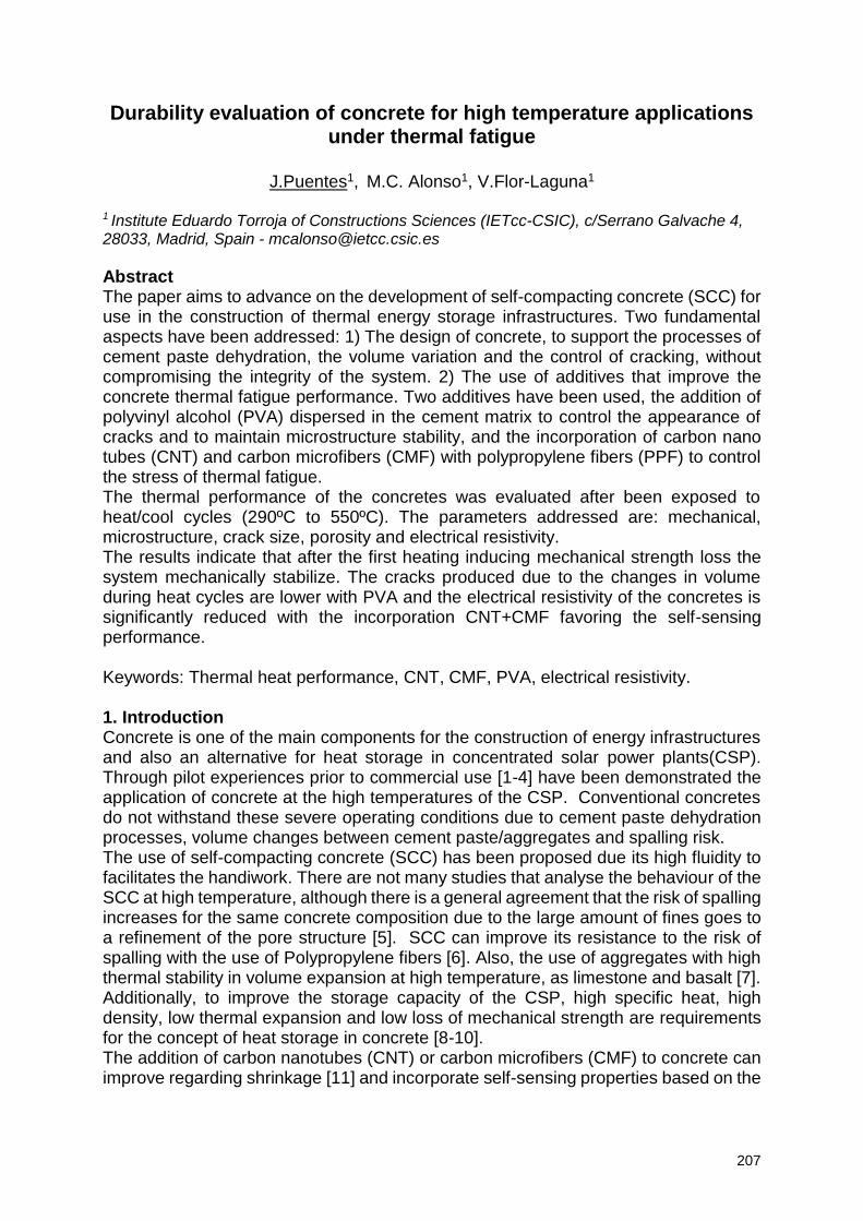
207
Durability evaluation of concrete for high temperature applications under thermal fatigue
J.Puentes1, M.C. Alonso1, V.Flor-Laguna1
1 Institute Eduardo Torroja of Constructions Sciences (IETcc-CSIC), c/Serrano Galvache 4, 28033, Madrid, Spain - [email protected]
Abstract The paper aims to advance on the development of self-compacting concrete (SCC) for use in the construction of thermal energy storage infrastructures. Two fundamental aspects have been addressed: 1) The design of concrete, to support the processes of cement paste dehydration, the volume variation and the control of cracking, without compromising the integrity of the system. 2) The use of additives that improve the concrete thermal fatigue performance. Two additives have been used, the addition of polyvinyl alcohol (PVA) dispersed in the cement matrix to control the appearance of cracks and to maintain microstructure stability, and the incorporation of carbon nano tubes (CNT) and carbon microfibers (CMF) with polypropylene fibers (PPF) to control the stress of thermal fatigue. The thermal performance of the concretes was evaluated after been exposed to heat/cool cycles (290ºC to 550ºC). The parameters addressed are: mechanical, microstructure, crack size, porosity and electrical resistivity. The results indicate that after the first heating inducing mechanical strength loss the system mechanically stabilize. The cracks produced due to the changes in volume during heat cycles are lower with PVA and the electrical resistivity of the concretes is significantly reduced with the incorporation CNT+CMF favoring the self-sensing performance. Keywords: Thermal heat performance, CNT, CMF, PVA, electrical resistivity. 1. Introduction Concrete is one of the main components for the construction of energy infrastructures and also an alternative for heat storage in concentrated solar power plants(CSP). Through pilot experiences prior to commercial use [1-4] have been demonstrated the application of concrete at the high temperatures of the CSP. Conventional concretes do not withstand these severe operating conditions due to cement paste dehydration processes, volume changes between cement paste/aggregates and spalling risk. The use of self-compacting concrete (SCC) has been proposed due its high fluidity to facilitates the handiwork. There are not many studies that analyse the behaviour of the SCC at high temperature, although there is a general agreement that the risk of spalling increases for the same concrete composition due to the large amount of fines goes to a refinement of the pore structure [5]. SCC can improve its resistance to the risk of spalling with the use of Polypropylene fibers [6]. Also, the use of aggregates with high thermal stability in volume expansion at high temperature, as limestone and basalt [7]. Additionally, to improve the storage capacity of the CSP, high specific heat, high density, low thermal expansion and low loss of mechanical strength are requirements for the concept of heat storage in concrete [8-10]. The addition of carbon nanotubes (CNT) or carbon microfibers (CMF) to concrete can improve regarding shrinkage [11] and incorporate self-sensing properties based on the
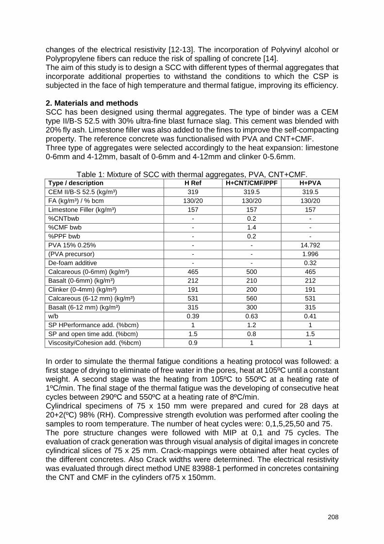
208
changes of the electrical resistivity [12-13]. The incorporation of Polyvinyl alcohol or Polypropylene fibers can reduce the risk of spalling of concrete [14]. The aim of this study is to design a SCC with different types of thermal aggregates that incorporate additional properties to withstand the conditions to which the CSP is subjected in the face of high temperature and thermal fatigue, improving its efficiency. 2. Materials and methods SCC has been designed using thermal aggregates. The type of binder was a CEM type II/B-S 52.5 with 30% ultra-fine blast furnace slag. This cement was blended with 20% fly ash. Limestone filler was also added to the fines to improve the self-compacting property. The reference concrete was functionalised with PVA and CNT+CMF. Three type of aggregates were selected accordingly to the heat expansion: limestone 0-6mm and 4-12mm, basalt of 0-6mm and 4-12mm and clinker 0-5.6mm.
Table 1: Mixture of SCC with thermal aggregates, PVA, CNT+CMF. Type / description H Ref H+CNT/CMF/PPF H+PVA
CEM II/B-S 52.5 (kg/m³) 319 319.5 319.5
FA (kg/m³) / % bcm 130/20 130/20 130/20
Limestone Filler (kg/m³) 157 157 157
%CNTbwb - 0.2 -
%CMF bwb - 1.4 -
%PPF bwb - 0.2 -
PVA 15% 0.25% - - 14.792
(PVA precursor) - - 1.996
De-foam additive - - 0.32
Calcareous (0-6mm) (kg/m³) 465 500 465
Basalt (0-6mm) (kg/m³) 212 210 212
Clinker (0-4mm) (kg/m³) 191 200 191
Calcareous (6-12 mm) (kg/m³) 531 560 531
Basalt (6-12 mm) (kg/m³) 315 300 315
w/b 0.39 0.63 0.41
SP HPerformance add. (%bcm) 1 1.2 1
SP and open time add. (%bcm) 1.5 0.8 1.5
Viscosity/Cohesion add. (%bcm) 0.9 1 1
In order to simulate the thermal fatigue conditions a heating protocol was followed: a first stage of drying to eliminate of free water in the pores, heat at 105ºC until a constant weight. A second stage was the heating from 105ºC to 550ºC at a heating rate of 1ºC/min. The final stage of the thermal fatigue was the developing of consecutive heat cycles between 290ºC and 550ºC at a heating rate of 8ºC/min. Cylindrical specimens of 75 x 150 mm were prepared and cured for 28 days at 20+2(ºC) 98% (RH). Compressive strength evolution was performed after cooling the samples to room temperature. The number of heat cycles were: 0,1,5,25,50 and 75. The pore structure changes were followed with MIP at 0,1 and 75 cycles. The evaluation of crack generation was through visual analysis of digital images in concrete cylindrical slices of 75 x 25 mm. Crack-mappings were obtained after heat cycles of the different concretes. Also Crack widths were determined. The electrical resistivity was evaluated through direct method UNE 83988-1 performed in concretes containing the CNT and CMF in the cylinders of75 x 150mm.
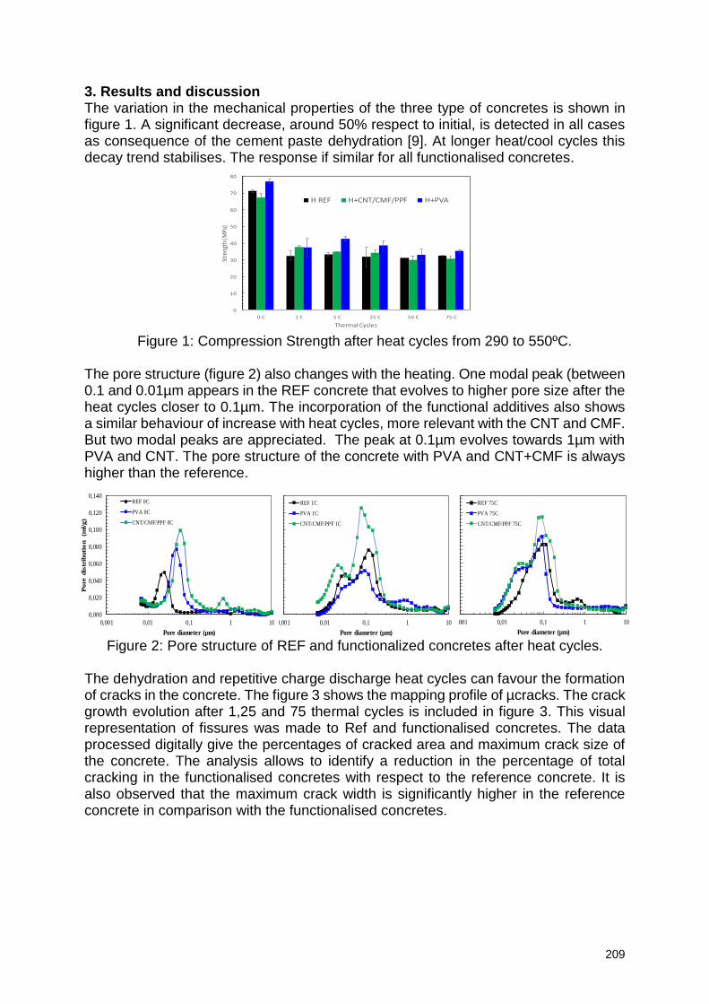
209
3. Results and discussion The variation in the mechanical properties of the three type of concretes is shown in figure 1. A significant decrease, around 50% respect to initial, is detected in all cases as consequence of the cement paste dehydration [9]. At longer heat/cool cycles this decay trend stabilises. The response if similar for all functionalised concretes.
Figure 1: Compression Strength after heat cycles from 290 to 550ºC.
The pore structure (figure 2) also changes with the heating. One modal peak (between 0.1 and 0.01µm appears in the REF concrete that evolves to higher pore size after the heat cycles closer to 0.1µm. The incorporation of the functional additives also shows a similar behaviour of increase with heat cycles, more relevant with the CNT and CMF. But two modal peaks are appreciated. The peak at 0.1µm evolves towards 1µm with PVA and CNT. The pore structure of the concrete with PVA and CNT+CMF is always higher than the reference.
Figure 2: Pore structure of REF and functionalized concretes after heat cycles. The dehydration and repetitive charge discharge heat cycles can favour the formation of cracks in the concrete. The figure 3 shows the mapping profile of µcracks. The crack growth evolution after 1,25 and 75 thermal cycles is included in figure 3. This visual representation of fissures was made to Ref and functionalised concretes. The data processed digitally give the percentages of cracked area and maximum crack size of the concrete. The analysis allows to identify a reduction in the percentage of total cracking in the functionalised concretes with respect to the reference concrete. It is also observed that the maximum crack width is significantly higher in the reference concrete in comparison with the functionalised concretes.
0,000
0,020
0,040
0,060
0,080
0,100
0,120
0,140
0,001 0,01 0,1 1 10
Po
re d
istr
ibu
tio
n
(ml/g
)
Pore diameter (µm)
REF 75C
PVA 75C
CNT/CMF/PPF 75C
0,000
0,020
0,040
0,060
0,080
0,100
0,120
0,140
0,001 0,01 0,1 1 10
Po
re d
istr
ibu
tio
n
(ml/
g)
Pore diameter (µm)
REF 1C
PVA 1C
CNT/CMF/PPF 1C
0,000
0,020
0,040
0,060
0,080
0,100
0,120
0,140
0,001 0,01 0,1 1 10
Pore
dis
trib
uti
on
(m
l/g)
Pore diameter (µm)
REF 0C
PVA 0C
CNT/CMF/PPF 0C
0
10
20
30
40
50
60
70
80
0 C 1 C 5 C 25 C 50 C 75 C
Stre
ngth
( M
Pa)
Thermal Cycles
H REF H+CNT/CMF/PPF H+PVA
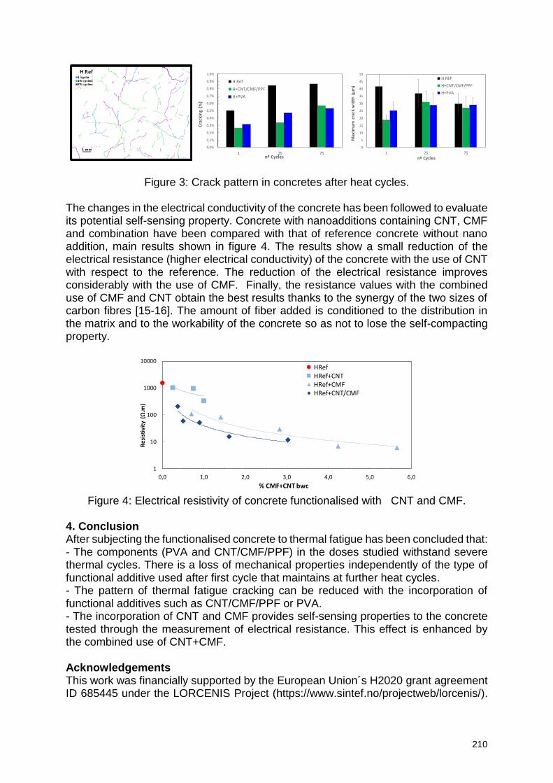
210
Figure 3: Crack pattern in concretes after heat cycles.
The changes in the electrical conductivity of the concrete has been followed to evaluate its potential self-sensing property. Concrete with nanoadditions containing CNT, CMF and combination have been compared with that of reference concrete without nano addition, main results shown in figure 4. The results show a small reduction of the electrical resistance (higher electrical conductivity) of the concrete with the use of CNT with respect to the reference. The reduction of the electrical resistance improves considerably with the use of CMF. Finally, the resistance values with the combined use of CMF and CNT obtain the best results thanks to the synergy of the two sizes of carbon fibres [15-16]. The amount of fiber added is conditioned to the distribution in the matrix and to the workability of the concrete so as not to lose the self-compacting property.
Figure 4: Electrical resistivity of concrete functionalised with CNT and CMF.
4. Conclusion After subjecting the functionalised concrete to thermal fatigue has been concluded that: - The components (PVA and CNT/CMF/PPF) in the doses studied withstand severe thermal cycles. There is a loss of mechanical properties independently of the type of functional additive used after first cycle that maintains at further heat cycles. - The pattern of thermal fatigue cracking can be reduced with the incorporation of functional additives such as CNT/CMF/PPF or PVA. - The incorporation of CNT and CMF provides self-sensing properties to the concrete tested through the measurement of electrical resistance. This effect is enhanced by the combined use of CNT+CMF. Acknowledgements This work was financially supported by the European Union´s H2020 grant agreement ID 685445 under the LORCENIS Project (https://www.sintef.no/projectweb/lorcenis/).
1
10
100
1000
10000
0,0 1,0 2,0 3,0 4,0 5,0 6,0
Re
sist
ivit
y (Ω
.m)
% CMF+CNT bwc
HRefHRef+CNTHRef+CMFHRef+CNT/CMF
0,0%
0,1%
0,2%
0,3%
0,4%
0,5%
0,6%
0,7%
0,8%
0,9%
1,0%
1 25 75
Cra
ckin
g (%
)
nº Cycles
H Ref
H+CNT/CMF/PPF
H+PVA
0
5
10
15
20
25
30
35
40
45
50
1 25 75
Max
imu
m c
rack
wid
th (
µm
)
nº Cycles
H REF
H+CNT/CMF/PPF
H+PVA
H Ref
211
Acknowledge to Dyckerhoff, NTUA, IK4-CIDETEC, LORCENIS partners, for supplying the cement, clinker aggregate, CNT and PVA. References [1] D. Laing, D. Lehmann, M. Fiß, C. Bahl, Test Results of Concrete Thermal Energy Storage for Parabolic Trough Power Plants. ASME. J. Sol. Energy Eng.131(4) (2009) 041007-1 to 041007-6. [2] D. Laing, D. Lehmann, C. Bahl, Concrete storage for solar thermal power plants and industrial process, IRES III 2008, 3rd International Renewable Energy Storage Conference, 2008, 24.-25.11. [3] M.C. Alonso, J. Vera-Agullo, L. Guerreiro, V. Flor-Laguna, M. Sanchez, and M. Collares-Pereira, Calcium aluminate based cement for concrete to be used as thermal energy storage in solar thermal electricity plants, Cement and Concrete Research, 82 (2016), 74-86. [4] E. John, M. Hale, P. Selvam, Concrete as a thermal energy storage medium for thermocline solar energy storage systems, Solar Energy, 96 (2013), 194-204. [5] H. Fares, A. Noumowe, S. Remond, Self-consolidating concrete subjected to high temperature: Mechanical and physicochemical properties, Cement and Concrete Research, Volume 39, Issue 12, (2009), pp 1230-1238 [6] Y. Ding, C. Zhang, M. Cao, Y. Zhang, C. Azevedo, Influence of different fibers on the change of pore pressure of self-consolidating concrete exposed to fire, Construction and Building Materials, Volume 113, (2016), pp 456-469 [7] Z. Xing, A. Beaucour, R. Hebert, A. Noumowe, B. Ledesert, Aggregate’s influence on thermophysical concrete properties at elevated temperature, Construction and Building Materials, Volume 95, (2015), pp 18-28 [8] M. Qianmin, G. Rongxin, Z. Zhiman, L. Zhiwei, H. Kecheng, Mechanical properties of concrete at high temperature—A review, Construction and Building Materials, Volume 93, (2015), pp 371-383. [9] P. Pimienta, R. Jansson McNamee, J.C. Mindeguia, Physical properties and behaviour of hihg performance concrete at high temperature, State of the art report RILEM TC 227-HPB, v29, Edt. Springer (2019)1-130. [10] R. L. Berger, Properties of concrete with cement clinker aggregate, Cem and conc Res, 4 (1974) 99-112 [8] W. Latif Baloch, R. Arsalan Khushnood, W. Khaliq, Influence of multi-walled carbon nanotubes on the residual performance of concrete exposed to high temperatures, Construction and Building Materials, Volume 185, (2018), pp 44-56 [9] S.J. Lee, I. You, G. Zi, D. Y. Yoo, Experimental Investigation of the Piezoresistive Properties of Cement Composites with Hybrid Carbon Fibers and Nanotubes. Sensors (2017), 17, 2516. [10] F. Azhari, N. Banthia, Cement-based sensors with carbon fibers and carbon nanotubes for piezoresistive sensing, Cement and Concrete Composites, Volume 34, Issue 7, (2012), pp 866-873, [11] J.-C. Liu, K. H. Tan, Mechanism of PVA fibers in mitigating explosive spalling of engineered cementitious composite at elevated temperature, Cement and Concrete Composites, Volume 93, (2018), pp 235-245. [12] L. Luo et al., Hybrid Effect of Carbon Fiber on Piezoresistivity of Carbon Nanotube Cement-Based Composite, Advanced Materials Research, Vols. 143-144, 2011, pp. 639-643
212
[13] D. Gao, M.S. Sturm, Y.L. Mo., Development of carbon nanofiber self-consolidating concrete. Proceedings pro065: 2nd International Symposium on Design, Performance and Use of Self-Consolidating Concrete SCC'2009 pp. 126 - 134
213
Durability performance of Fiber Engineered Cementitious Materials (FECM) with slurry lime (SL) addition
C.G.R. Mircea1, H. Szilágyi2, C. Baeră3
, A.C. Mircea1,2
1 Technical University of Cluj-Napoca, Civil Engineering Faculty, C-tin Daicoviciu 15, 400020 Cluj-Napoca, Romania – [email protected] 2 N.I.R.D. URBAN-INCERC, Cluj-Napoca Branch, Calea Florești 117, 400524, Cluj-Napoca, Romania, – [email protected], [email protected] 3 N.I.R.D. URBAN-INCERC, Timișoara Branch, Traian Lalescu 2, 300223, Timișoara, Romania – [email protected]
Abstract Fibre Engineered Cementitious Materials (FECM) are a high performance type of polymeric fiber composites studied, developed and constantly improved at NIRD “URBAN-INCERC” Cluj-Napoca Branch in the latest period. The high deformability of the composites, atypical for traditional cementitious materials, can be achieved by controlled microcracking behaviour under loading, specific for the Strain Hardening Cementitious Composites (SHCC). The metal like behavior and high strain capacity, clearly emphasized under tensile stresses, represents the source of material superior performance. Apart from the increased mechanical capacity, the durability and generally the long term performance of the FECMs represent an important topic of investigation in order to proper establish the domain of applicability for these relatively new types of materials. The aim of this paper is to present the results of the experimental investigation concerning the material durability when exposed to specific freeze-thaw cycles. The initial of FECM mixes, optimized with Slurry Lime (SL) addition replacing the lime powder (L), initially used for controlling the fresh state consistency and the bleeding tendency, offered positive results in terms of mechanical performance and self-healing capacity as well (crack closing and tensile capacity recovery after healing). Consequently, the SL-FECM composites were selected for a complex evaluation of long –term investigations in order to determine their viability and of the SL addition in the FECM matrix, as well. The long-term investigation is ongoing procedure but relevant results concerning the exposure to severe freeze-thaw cycles, performed in accordance to Romanian valid testing methodology, could provide significant conclusions with respect to material performance and its potential practical use. Keywords: fibre engineered cementitious materials (FECM), lime slurry (SL), waste prevention, durability. 1. Introduction NIRD “URBAN-INCERC” Cluj-Napoca Branch, in the latest fifteen years, conducted a complex research programme concerning the structural design optimization of the seismic resistant joints for precast structures and also the development of high performance cementitious composites, namely the Fibre Engineered Cementitious Materials (FECM), as grouts, filing materials for the critical areas of the tested prototypes [1], or even for the structural members of the element (e.g., beam, column). As previously mentioned [1], the FECMs basically represent an Engineering Cementitious Composite (ECC) typology of materials, developed with predominant
214
local, Romanian raw materials for economic and obvious feasibility reasons. The high deformability induced by the microcracking behavior under stress, the psychical and mechanical performance together with the self-healing capacity of the composites, as direct consequence of the mix design and controlled width of the crack under loading, recommend them for the specified purpose. The long term and the durability performances became topics of high interest regarding the FECM mixes which already proved compositional stability and best early age performances. The long term and the durability characteristics are essential for proper evaluation of the applicability of the materials, especially considering the specificity of Romania (climate, seismicity and corresponding design codes, etc.). 2. Materials and methods The FECM mix design involves the typical binding system with large fly ash (FA) content as main addition, exceeding the cement (C) content with 20% (1.2 C/FA ratio), in order to obtain a lubricated matrix [2], [3]. Together with the fine silica sand (SS) as aggregate and 2% polymeric fibre (by volume) as disperse reinforcement of the cementitious matrix, there it is generated the successive, width controlled microcracks succession of the composite, under loading. The aggregates (SS) and the binding components (C and FA) are of Romanian provenance, locally available. Several experimental attempts of using the local available Polypropylene fibres (PP_hyb) did not offer the expected results. It was confirmed that lubricated PVA fibers (Kuraray, Japan) performed best in terms of multiple cracking development under loading, when compared to the PP (local sources), according to the four point bending flexural testing (4PB), as traditional method for ECC ductility enhancement. The PVA-FECM mixes, initially containing a small addition of lime powder (L) for fresh state improvement and potential bleeding control [1] were slightly changed: a Slurry Lime (SL) addition was used as lime powder (L) replacement, for the eventual bleeding prevention. The used Slurry Lime (SL) represents a waste generated by the local industry of limestone processing. It showed good compatibility to the fly ash (FA) content and led to improve of mechanical performance as well, according to the early age evaluation, namely the comparative analysis involving the reference. The effect of mechanical performance improvement, initially noticed in concrete mixes with high volume fly ash (HVFA), was confirmed further on by the SL-FECM mixes. The SL integration in the mix was performed as such, by simply controlling the water intake by considering the natural water content of the used SL sample. This procedure proved satisfactory results, from the economic point of view as well, The durability performance of the SL-FECM mixes was evaluated by using the destructive method, in accordance to the Romanian norm SR 3518:2009 [4], by determining the freeze/thaw degree (η), which emphasizes the mechanical loss, (the flexural and compressive strength loss) of the samples exposed (E) to the 50 and respectively 100 freeze and thaw aggressive cycles, with respect to the reference specimens (M). The testing method was performed by using 28 days old prismatic specimens 40 x 40 x160 mm3 and included specific flexural (3PB) and compressive tests, in accordance to EN 196 (Fig. 1, a and b). The freeze and thaw cycles include two alternating phases exposure: the freeze phase, namely the 12 h exposure of specimens in air, at temperature (T) of (21 ± 3)°C and the relative humidity (RH) (50 ± 5), followed by the thaw phase, of 12 h immersion of specimens in tap water at T: (20 ± 5)°C. The pass from freeze to thaw exposure represents an aggressive switch, of approximate 40°C, from air to water (or humid air, RH>90%). During the 50 and respectively 100 freeze and thaw cycles of the exposed
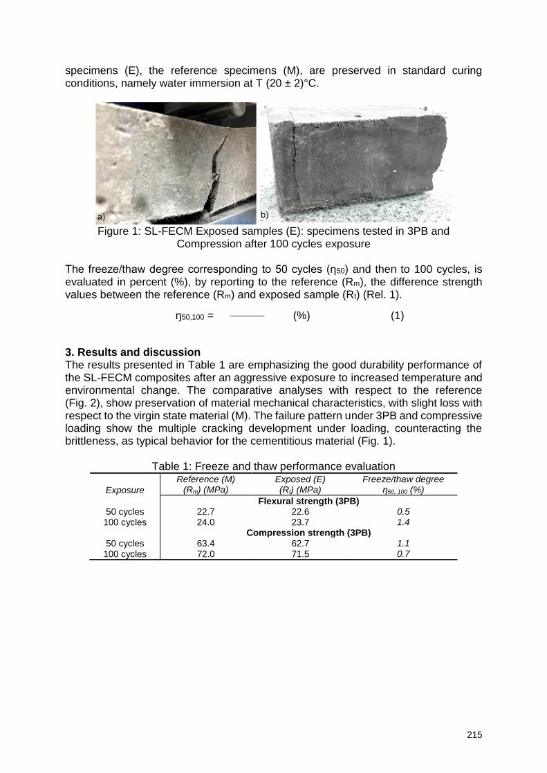
215
specimens (E), the reference specimens (M), are preserved in standard curing conditions, namely water immersion at T (20 ± 2)°C.
Figure 1: SL-FECM Exposed samples (E): specimens tested in 3PB and
Compression after 100 cycles exposure
The freeze/thaw degree corresponding to 50 cycles (η50) and then to 100 cycles, is evaluated in percent (%), by reporting to the reference (Rm), the difference strength values between the reference (Rm) and exposed sample (Rt) (Rel. 1).
ŋ50,100 = (%) (1)
3. Results and discussion The results presented in Table 1 are emphasizing the good durability performance of the SL-FECM composites after an aggressive exposure to increased temperature and environmental change. The comparative analyses with respect to the reference (Fig. 2), show preservation of material mechanical characteristics, with slight loss with respect to the virgin state material (M). The failure pattern under 3PB and compressive loading show the multiple cracking development under loading, counteracting the brittleness, as typical behavior for the cementitious material (Fig. 1).
Table 1: Freeze and thaw performance evaluation
Exposure
Reference (M) (Rm) (MPa)
Exposed (E) (Rt) (MPa)
Freeze/thaw degree η50, 100 (%)
Flexural strength (3PB) 50 cycles 22.7 22.6 0.5
100 cycles 24.0 23.7 1.4 Compression strength (3PB)
50 cycles 63.4 62.7 1.1 100 cycles 72.0 71.5 0.7
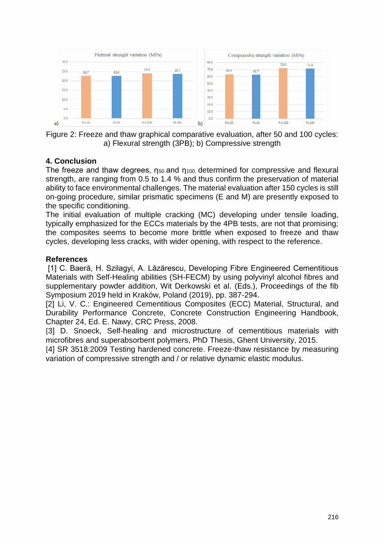
216
Figure 2: Freeze and thaw graphical comparative evaluation, after 50 and 100 cycles:
a) Flexural strength (3PB); b) Compressive strength 4. Conclusion The freeze and thaw degrees, η50 and η100, determined for compressive and flexural strength, are ranging from 0.5 to 1.4 % and thus confirm the preservation of material ability to face environmental challenges. The material evaluation after 150 cycles is still on-going procedure, similar prismatic specimens (E and M) are presently exposed to the specific conditioning. The initial evaluation of multiple cracking (MC) developing under tensile loading, typically emphasized for the ECCs materials by the 4PB tests, are not that promising; the composites seems to become more brittle when exposed to freeze and thaw cycles, developing less cracks, with wider opening, with respect to the reference. References [1] C. Baeră, H. Szilagyi, A. Lăzărescu, Developing Fibre Engineered Cementitious Materials with Self-Healing abilities (SH-FECM) by using polyvinyl alcohol fibres and supplementary powder addition, Wit Derkowski et al. (Eds.), Proceedings of the fib Symposium 2019 held in Kraków, Poland (2019), pp. 387-294. [2] Li, V. C.: Engineered Cementitious Composites (ECC) Material, Structural, and Durability Performance Concrete, Concrete Construction Engineering Handbook, Chapter 24, Ed. E. Nawy, CRC Press, 2008. [3] D. Snoeck, Self-healing and microstructure of cementitious materials with
microfibres and superabsorbent polymers, PhD Thesis, Ghent University, 2015. [4] SR 3518:2009 Testing hardened concrete. Freeze-thaw resistance by measuring
variation of compressive strength and / or relative dynamic elastic modulus.
217
Impact of Super Absorbent Polymers on Early Age Behavior of Ultra-High Performance Concrete Walls
Judy Kheir1,2, L. De Meyst1, J.R. Tenório Filho1, T.A. Hammer3, A. Klausen4 , B.
Hilloulin2, A. Loukili2, N. De Belie1
1 Magnel Laboratory for Concrete Research, Ghent University, Technologiepark Zwijnaarde 60, B-9052 Ghent, Belgium – e-mail: [email protected]; [email protected]; [email protected]; [email protected] 2 Institut de Recherche en Génie Civil et Mécanique (GeM), Ecole Centrale de Nantes, LUNAM Université, UMR-CNRS 6183, 1 rue de la Noë, 44321 Nantes, France – e-mail: [email protected] ; [email protected] ; [email protected] 3 Architecture, Materials and Structures, SINTEF Building and Infrastructure, N-7465 Trondheim, Norway – e-mail: [email protected] 4 The Norwegian University of Science And Technology-NTNU, N-7491 Trondheim, Norway – e-mail: [email protected]
Abstract Early age cracking, a common problem for Ultra-High Performance Concrete (UHPC), is caused by Autogenous Shrinkage (AS) and self-desiccation arising from the chemical shrinkage during the cement hydration reactions when the deformation is restrained. However, to avoid the crack development initiated by AS, several solutions can be adopted; one example is the addition of a promising material, considered as an internal curing agent, the Super Absorbent Polymers (SAP) which limits the capillary depressions that can enhance the formation of the crack. In this study the main goal is to mitigate the shrinkage using SAPs in infrastructure under severe conditions. Therefore, a demonstrator wall was built simulating a typical case with high risk of cracking. With the help of fiber optic SOFO sensors embedded in the wall, real-time deformations are recorded and compared the demountable mechanical strain gauges (DEMEC) measurements to further investigate the behavior of SAPs in real scale infrastructure. The amount of extra water (in SAP) needed to mitigate shrinkage was determined by performing chemical shrinkage tests on different cement paste combinations. Tests of autogenous shrinkage were performed on mortars using corrugated tubes and showed that SAPs reduce to some extent the AS. Under restrained conditions via ring tests, SAP specimens did not crack. Therefore, SAPs were found promising towards mitigating the shrinkage and enhancing the early age behavior of concrete for a better durability. Keywords: Autogenous Shrinkage, Super Absorbent Polymers (SAP), Early-Age cracking, Ultra-High Performance Concrete (UHPC) 1. Introduction The prediction of the early age behavior of cementitious materials is a difficult task, because many of the material properties are very sensitive to curing conditions as it is the case for UHPC, which usually have a very low water to cement ratio (0.2 < w/c < 0.3) [1][2]. Due to the excellent mechanical properties and exceptional durability UHPC is a highly demanded type of concrete nowadays. The challenge is the risk of early age cracking, since UHPC has a significant autogenous shrinkage which develops fast, typically within the first days of age. The functionality and durability of these structures is compromised by the formation of the cracks. It is very important to correctly estimate the evolution of AS deformations in order to limit the cracking risk [3]. Early age properties must be investigated in order to enhance the lifetime of these reinforced concrete infrastructures operating under severe conditions. Therefore, an early age crack assessment was done to decide on the design
218
for a reference UHPC wall without SAP which would show early age cracking. This will then be compared to a wall containing SAP in order to mitigate shrinkage cracking. 2. Materials and Methods Commercial SAPs based on poly(acrylamide-co-acrylic acid) were used in the restrained and autogenous shrinkage tests for the wall. These SAPs have an average dry particle size of 40 μm and an absorption capacity in cement slurry equal to 27g/g of SAP. 2.1 Parameter determination for simulation of the UHPC wall To simulate the strains in an UHPC wall, cast on a non-deforming slab, a set of parameters is needed, resulting from specific experiments on the investigated concrete, of which the mix design can be found in Table 1. According to a procedure developed by Klausen [4], the parameters are the following:
Hydration heat development (measured)
Activation energy (assumed based on experience)
Compressive and uniaxial tensile strength development (measured)
Coefficient of thermal expansion - CTE (measured)
Creep (measured)
Autogenous shrinkage - AS (measured)
In addition, one test was performed in the Temperature-Stress Testing Machine (TSTM) system, see Figure 1, and two tests were performed in the Free Deformation (FD) system. The test in the TSTM was performed under realistic temperature curing conditions i.e. simulating the heat of hydration in a 50 mm thick wall, whereas the tests in the FD system were performed under 20 °C isothermal curing conditions. Material models and corresponding model parameters describing the property development over time for the given concrete were deduced based on the above described tests. The TSTM System used (NTNU, Trondheim, Norway) consists of a dilation rig and a TSTM. Both rigs are connected to a temperature-control system, which can provide an accurate control of the concrete temperature during testing. The dilation rig measures the free deformation, i.e. thermal dilation (TD) and autogenous deformation (AD), of a sealed concrete specimen. The TSTM is constructed to measure the stress generation of a sealed concrete specimen during the hardening phase under a chosen degree of restraint (R). For the current test, the degree of restraint was set to R = 30%. During the test in the TSTM, a set of comprehensive stress-strain relations over time is obtained. These stress-strain relations provide an incremental E-modulus development (i.e. obtained from incremental loading) over time for the concrete in question. Results from the TSTM tests are also used to determine the start time for stress calculations, t0 (here 8 h), and the coefficient of thermal expansion (CTE). The FD system measures autogenous shrinkage under 20 °C isothermal curing conditions on sealed prisms with dimensions 100x100x500mm.
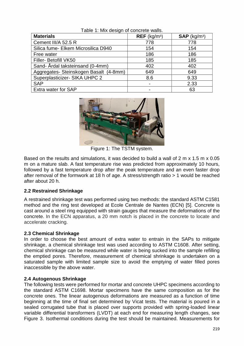
219
Table 1: Mix design of concrete walls.
Materials REF (kg/mᶾ) SAP (kg/mᶾ) Cement III/A 52.5 R 778 778
Silica fume- Elkem Microsilica D940 154 154
Free water 186 186
Filler- Betofill VK50 185 185
Sand- Årdal taksteinsand (0-4mm) 402 402
Aggregates- Steinskogen Basalt (4-8mm) 649 649
Superplasticizer- SIKA UHPC 2 8.6 9.33
SAP - 2.33
Extra water for SAP - 63
Figure 1: The TSTM system.
Based on the results and simulations, it was decided to build a wall of 2 m x 1.5 m x 0.05 m on a mature slab. A fast temperature rise was predicted from approximately 10 hours, followed by a fast temperature drop after the peak temperature and an even faster drop after removal of the formwork at 18 h of age. A stress/strength ratio > 1 would be reached after about 20 h.
2.2 Restrained Shrinkage
A restrained shrinkage test was performed using two methods: the standard ASTM C1581 method and the ring test developed at Ecole Centrale de Nantes (ECN) [5]. Concrete is cast around a steel ring equipped with strain gauges that measure the deformations of the concrete. In the ECN apparatus, a 20 mm notch is placed in the concrete to locate and accelerate cracking. 2.3 Chemical Shrinkage In order to choose the best amount of extra water to entrain in the SAPs to mitigate shrinkage, a chemical shrinkage test was used according to ASTM C1608. After setting, chemical shrinkage can be measured while water is being sucked into the sample refilling the emptied pores. Therefore, measurement of chemical shrinkage is undertaken on a saturated sample with limited sample size to avoid the emptying of water filled pores inaccessible by the above water. 2.4 Autogenous Shrinkage The following tests were performed for mortar and concrete UHPC specimens according to the standard ASTM C1698. Mortar specimens have the same composition as for the concrete ones. The linear autogenous deformations are measured as a function of time beginning at the time of final set determined by Vicat tests. The material is poured in a sealed corrugated tube that is placed over supports provided with spring-loaded linear variable differential transformers (LVDT) at each end for measuring length changes, see Figure 3. Isothermal conditions during the test should be maintained. Measurements for
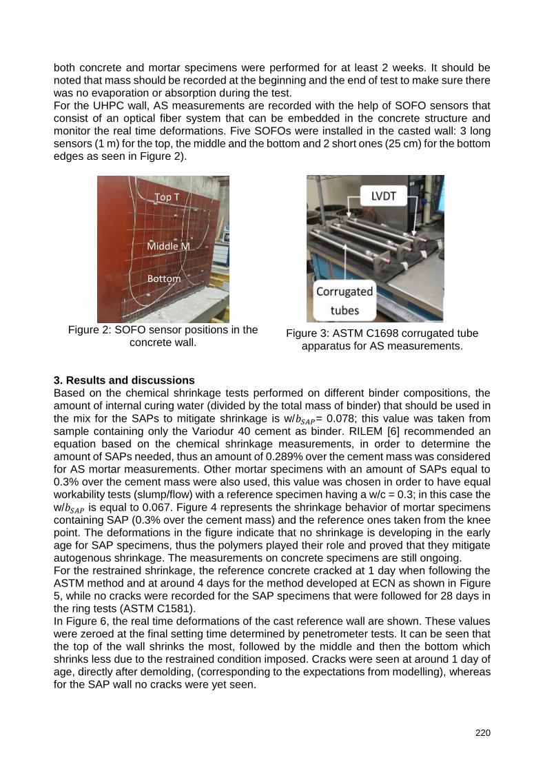
220
both concrete and mortar specimens were performed for at least 2 weeks. It should be noted that mass should be recorded at the beginning and the end of test to make sure there was no evaporation or absorption during the test. For the UHPC wall, AS measurements are recorded with the help of SOFO sensors that consist of an optical fiber system that can be embedded in the concrete structure and monitor the real time deformations. Five SOFOs were installed in the casted wall: 3 long sensors (1 m) for the top, the middle and the bottom and 2 short ones (25 cm) for the bottom edges as seen in Figure 2).
Figure 2: SOFO sensor positions in the
concrete wall.
Figure 3: ASTM C1698 corrugated tube
apparatus for AS measurements.
3. Results and discussions Based on the chemical shrinkage tests performed on different binder compositions, the amount of internal curing water (divided by the total mass of binder) that should be used in the mix for the SAPs to mitigate shrinkage is w/𝑏𝑆𝐴𝑃= 0.078; this value was taken from sample containing only the Variodur 40 cement as binder. RILEM [6] recommended an equation based on the chemical shrinkage measurements, in order to determine the amount of SAPs needed, thus an amount of 0.289% over the cement mass was considered for AS mortar measurements. Other mortar specimens with an amount of SAPs equal to 0.3% over the cement mass were also used, this value was chosen in order to have equal workability tests (slump/flow) with a reference specimen having a w/c = 0.3; in this case the w/𝑏𝑆𝐴𝑃 is equal to 0.067. Figure 4 represents the shrinkage behavior of mortar specimens containing SAP (0.3% over the cement mass) and the reference ones taken from the knee point. The deformations in the figure indicate that no shrinkage is developing in the early age for SAP specimens, thus the polymers played their role and proved that they mitigate autogenous shrinkage. The measurements on concrete specimens are still ongoing. For the restrained shrinkage, the reference concrete cracked at 1 day when following the ASTM method and at around 4 days for the method developed at ECN as shown in Figure 5, while no cracks were recorded for the SAP specimens that were followed for 28 days in the ring tests (ASTM C1581). In Figure 6, the real time deformations of the cast reference wall are shown. These values were zeroed at the final setting time determined by penetrometer tests. It can be seen that the top of the wall shrinks the most, followed by the middle and then the bottom which shrinks less due to the restrained condition imposed. Cracks were seen at around 1 day of age, directly after demolding, (corresponding to the expectations from modelling), whereas for the SAP wall no cracks were yet seen.
B1
B2 B3
Top T
Middle M
Bottom
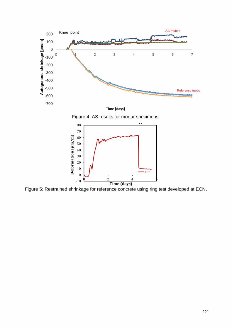
221
Figure 4: AS results for mortar specimens.
Figure 5: Restrained shrinkage for reference concrete using ring test developed at ECN.
-700
-600
-500
-400
-300
-200
-100
0
100
200
0 1 2 3 4 5 6 7
Au
tog
en
ou
s s
hri
nkag
e [
µm
/m]
Time [days]
Knee point
Reference tubes
SAP tubes
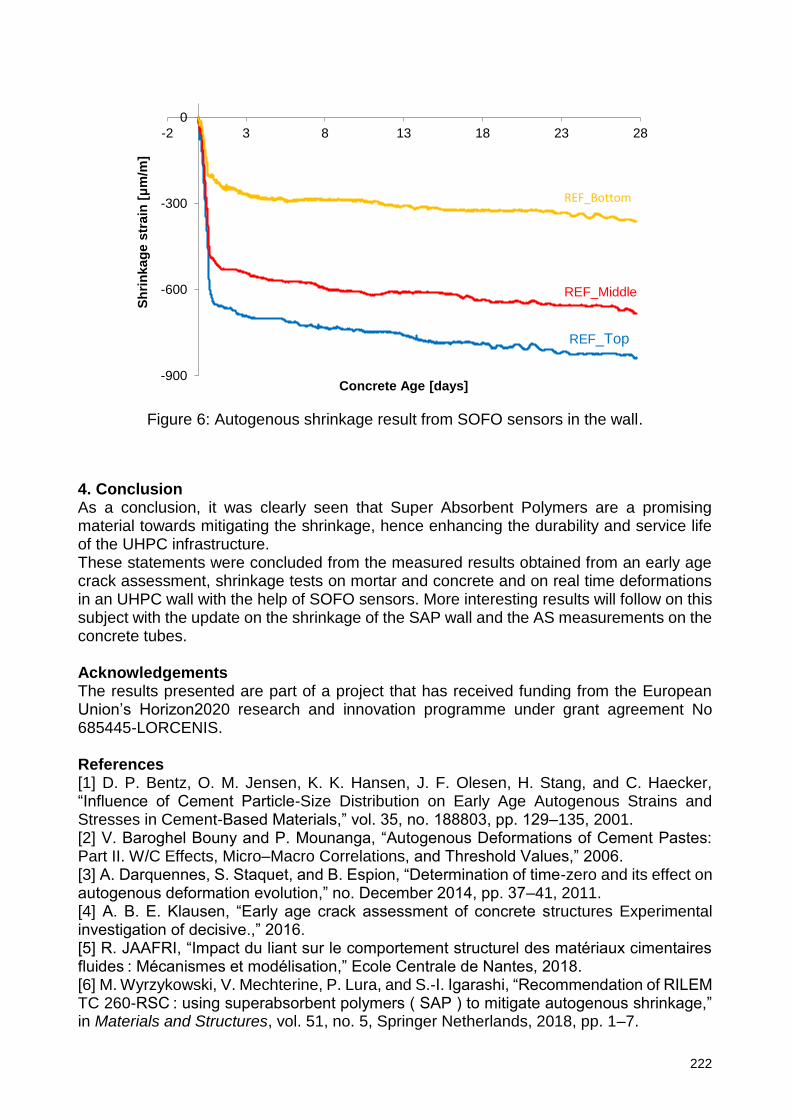
222
Figure 6: Autogenous shrinkage result from SOFO sensors in the wall.
4. Conclusion As a conclusion, it was clearly seen that Super Absorbent Polymers are a promising material towards mitigating the shrinkage, hence enhancing the durability and service life of the UHPC infrastructure. These statements were concluded from the measured results obtained from an early age crack assessment, shrinkage tests on mortar and concrete and on real time deformations in an UHPC wall with the help of SOFO sensors. More interesting results will follow on this subject with the update on the shrinkage of the SAP wall and the AS measurements on the concrete tubes. Acknowledgements The results presented are part of a project that has received funding from the European Union’s Horizon2020 research and innovation programme under grant agreement No 685445-LORCENIS. References [1] D. P. Bentz, O. M. Jensen, K. K. Hansen, J. F. Olesen, H. Stang, and C. Haecker, “Influence of Cement Particle-Size Distribution on Early Age Autogenous Strains and Stresses in Cement-Based Materials,” vol. 35, no. 188803, pp. 129–135, 2001. [2] V. Baroghel Bouny and P. Mounanga, “Autogenous Deformations of Cement Pastes: Part II. W/C Effects, Micro–Macro Correlations, and Threshold Values,” 2006. [3] A. Darquennes, S. Staquet, and B. Espion, “Determination of time-zero and its effect on autogenous deformation evolution,” no. December 2014, pp. 37–41, 2011. [4] A. B. E. Klausen, “Early age crack assessment of concrete structures Experimental investigation of decisive.,” 2016. [5] R. JAAFRI, “Impact du liant sur le comportement structurel des matériaux cimentaires fluides : Mécanismes et modélisation,” Ecole Centrale de Nantes, 2018. [6] M. Wyrzykowski, V. Mechterine, P. Lura, and S.-I. Igarashi, “Recommendation of RILEM TC 260-RSC : using superabsorbent polymers ( SAP ) to mitigate autogenous shrinkage,” in Materials and Structures, vol. 51, no. 5, Springer Netherlands, 2018, pp. 1–7.
-900
-600
-300
0
-2 3 8 13 18 23 28S
hri
nkag
e s
train
[μ
m/m
]
Concrete Age [days]
REF_Top
REF_Bottom
REF_Middle
223
The Effect of Alkali to Fly Ash Ratio on the Durability of Geopolymer Mortar Against the Coupled Actions
of Chemicals and High Thermal Cycles
Sukanta Kumer Shill1, Frederick Robert Thomas Funnell1, Safat Al-Deen1
1School of engineering and information technology, the University of New South Wales, Canberra, Australia - [email protected] ; [email protected]; [email protected]
Abstract The present study investigates the performance of fly ash (FA) based geopolymer (GP) mortar (3 and 28-day old) under the combined effect of aviation oils and high thermal cycles. Cubic specimens of GP mortar were repeatedly exposed to both aviation oils and high thermal cycles simultaneously. After a couple of cycles of exposure, all GP specimens underwent saponification process, which possibly weakened the compressive strength of the GP mortar. Upon the 60th cycle of exposure, the 3 and 28-day old GP lost a maximum of 44.23% and 33.72% of the compressive strength compared to the original values, respectively. However, the GP mortar did not suffer scaling on the surface even after 60 cycles of exposure in 5 months. The FA to alkali liquids (AL), (FA/AL), ratio plays an important role in the compressive strength degradation process of GP mortar. The study also reports a suitable AL/FA ratio for GP mix that could be used to patch repair for scaled concrete at military airbases. Keywords: Geopolymer mortar, durability, saponification, compressive strength, high thermal cycles, chemical damages.
1. Introduction The conventional Portland cement (PC) concrete aprons that house Air Force’s and Navy’s aircraft have been experiencing degradation issue in terms of surface scaling [1-5]. As, reported, the simultaneous actions of exhaust heat from auxiliary power units (APUs) of jets and spillage of aviation oils on the concrete apron from the routine operation/maintenance causes rapid scaling on the surface [4, 5]. APUs exhaust of F/A-18s aircraft can heat the surface temperature of traditional concrete up to 175
in 12 minutes with a heating rate of approximately 70/min within the first 2 minutes [4, 6]. Based on the technical and environmental point of view, GP can be a superior alternative to traditional PC concrete [7-11]. This eco-friendly new cementitious material is not only being researched; it has also been used in the heavy-duty rigid pavements at a commercial airport in Brisbane, Australia [12]. Based on a review of the literature, it is reported that GP could be a superior alternative to conventional PC to repair scaled concrete apron at army airbases [4, 13]. Additinally, according to the Waterways Experiment Station (WES) of the US Army Corps of Engineers, FA-based alkali activated aluminosilicate binder can be a potential binder in repairing army airbases and any other special construction needs [14]. However, the performance of GP under the combined actions of aviation oils and high thermal cycles has not yet been investigated. Therefore, before the use of GP at army airbases, its performances under simultaneous actions of aviation oils and high thermal cycles needs to be assessed.
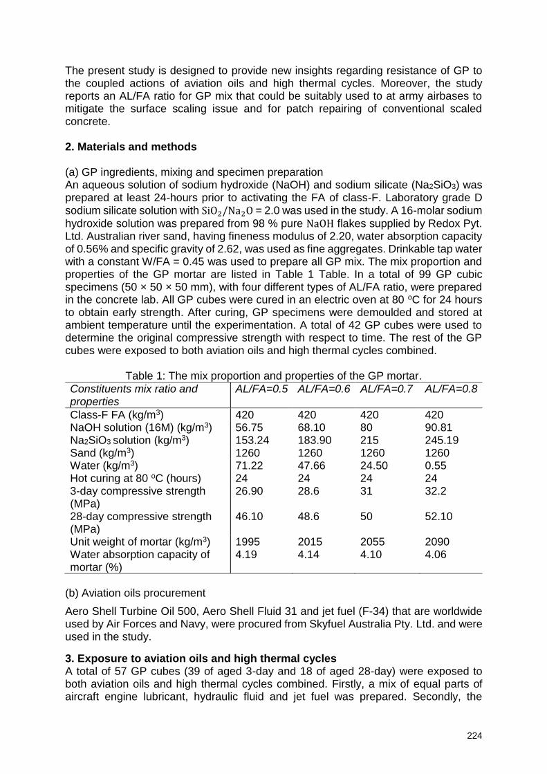
224
The present study is designed to provide new insights regarding resistance of GP to the coupled actions of aviation oils and high thermal cycles. Moreover, the study reports an AL/FA ratio for GP mix that could be suitably used to at army airbases to mitigate the surface scaling issue and for patch repairing of conventional scaled concrete. 2. Materials and methods (a) GP ingredients, mixing and specimen preparation An aqueous solution of sodium hydroxide (NaOH) and sodium silicate (Na2SiO3) was prepared at least 24-hours prior to activating the FA of class-F. Laboratory grade D sodium silicate solution with SiO2/Na2O = 2.0 was used in the study. A 16-molar sodium
hydroxide solution was prepared from 98 % pure NaOH flakes supplied by Redox Pyt. Ltd. Australian river sand, having fineness modulus of 2.20, water absorption capacity of 0.56% and specific gravity of 2.62, was used as fine aggregates. Drinkable tap water with a constant W/FA = 0.45 was used to prepare all GP mix. The mix proportion and properties of the GP mortar are listed in Table 1 Table. In a total of 99 GP cubic specimens (50 × 50 × 50 mm), with four different types of AL/FA ratio, were prepared in the concrete lab. All GP cubes were cured in an electric oven at 80 oC for 24 hours to obtain early strength. After curing, GP specimens were demoulded and stored at ambient temperature until the experimentation. A total of 42 GP cubes were used to determine the original compressive strength with respect to time. The rest of the GP cubes were exposed to both aviation oils and high thermal cycles combined.
Table 1: The mix proportion and properties of the GP mortar.
Constituents mix ratio and properties
AL/FA=0.5 AL/FA=0.6 AL/FA=0.7 AL/FA=0.8
Class-F FA (kg/m3) 420 420 420 420 NaOH solution (16M) (kg/m3) 56.75 68.10 80 90.81 Na2SiO3 solution (kg/m3) 153.24 183.90 215 245.19 Sand (kg/m3) 1260 1260 1260 1260 Water (kg/m3) 71.22 47.66 24.50 0.55 Hot curing at 80 oC (hours) 24 24 24 24 3-day compressive strength (MPa)
26.90 28.6 31 32.2
28-day compressive strength (MPa)
46.10 48.6 50 52.10
Unit weight of mortar (kg/m3) 1995 2015 2055 2090 Water absorption capacity of mortar (%)
4.19 4.14 4.10 4.06
(b) Aviation oils procurement
Aero Shell Turbine Oil 500, Aero Shell Fluid 31 and jet fuel (F-34) that are worldwide used by Air Forces and Navy, were procured from Skyfuel Australia Pty. Ltd. and were used in the study.
3. Exposure to aviation oils and high thermal cycles A total of 57 GP cubes (39 of aged 3-day and 18 of aged 28-day) were exposed to both aviation oils and high thermal cycles combined. Firstly, a mix of equal parts of aircraft engine lubricant, hydraulic fluid and jet fuel was prepared. Secondly, the
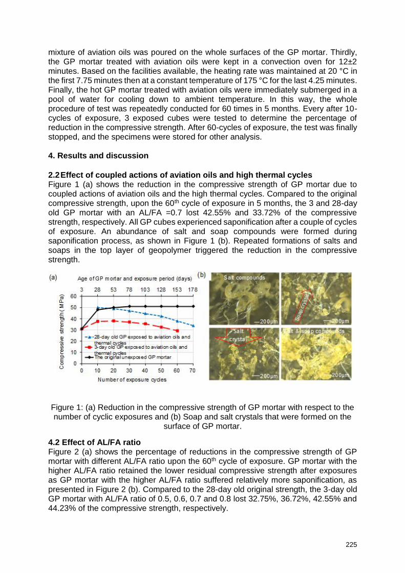
225
mixture of aviation oils was poured on the whole surfaces of the GP mortar. Thirdly, the GP mortar treated with aviation oils were kept in a convection oven for 12±2 minutes. Based on the facilities available, the heating rate was maintained at 20 °C in the first 7.75 minutes then at a constant temperature of 175 °C for the last 4.25 minutes. Finally, the hot GP mortar treated with aviation oils were immediately submerged in a pool of water for cooling down to ambient temperature. In this way, the whole procedure of test was repeatedly conducted for 60 times in 5 months. Every after 10-cycles of exposure, 3 exposed cubes were tested to determine the percentage of reduction in the compressive strength. After 60-cycles of exposure, the test was finally stopped, and the specimens were stored for other analysis. 4. Results and discussion 2.2 Effect of coupled actions of aviation oils and high thermal cycles Figure 1 (a) shows the reduction in the compressive strength of GP mortar due to coupled actions of aviation oils and the high thermal cycles. Compared to the original compressive strength, upon the 60th cycle of exposure in 5 months, the 3 and 28-day old GP mortar with an AL/FA =0.7 lost 42.55% and 33.72% of the compressive strength, respectively. All GP cubes experienced saponification after a couple of cycles of exposure. An abundance of salt and soap compounds were formed during saponification process, as shown in Figure 1 (b). Repeated formations of salts and soaps in the top layer of geopolymer triggered the reduction in the compressive strength.
Figure 1: (a) Reduction in the compressive strength of GP mortar with respect to the number of cyclic exposures and (b) Soap and salt crystals that were formed on the
surface of GP mortar.
4.2 Effect of AL/FA ratio Figure 2 (a) shows the percentage of reductions in the compressive strength of GP mortar with different AL/FA ratio upon the 60th cycle of exposure. GP mortar with the higher AL/FA ratio retained the lower residual compressive strength after exposures as GP mortar with the higher AL/FA ratio suffered relatively more saponification, as presented in Figure 2 (b). Compared to the 28-day old original strength, the 3-day old GP mortar with AL/FA ratio of 0.5, 0.6, 0.7 and 0.8 lost 32.75%, 36.72%, 42.55% and 44.23% of the compressive strength, respectively.
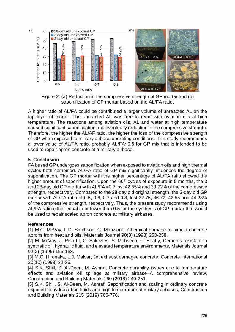
226
Figure 2: (a) Reduction in the compressive strength of GP mortar and (b)
saponification of GP mortar based on the AL/FA ratio.
A higher ratio of AL/FA could be contributed a larger volume of unreacted AL on the top layer of mortar. The unreacted AL was free to react with aviation oils at high temperature. The reactions among aviation oils, AL and water at high temperature caused significant saponification and eventually reduction in the compressive strength. Therefore, the higher the AL/AF ratio, the higher the loss of the compressive strength of GP when exposed to military airbase operating conditions. This study recommends a lower value of AL/FA ratio, probably AL/FA≤0.5 for GP mix that is intended to be used to repair apron concrete at a military airbase.
5. Conclusion FA based GP undergoes saponification when exposed to aviation oils and high thermal cycles both combined. AL/FA ratio of GP mix significantly influences the degree of saponification. The GP mortar with the higher percentage of AL/FA ratio showed the higher amount of saponification. Upon the 60th cycles of exposure in 5 months, the 3 and 28-day old GP mortar with AL/FA =0.7 lost 42.55% and 33.72% of the compressive strength, respectively. Compared to the 28-day old original strength, the 3-day old GP mortar with AL/FA ratio of 0.5, 0.6, 0.7 and 0.8, lost 32.75, 36.72, 42.55 and 44.23% of the compressive strength, respectively. Thus, the present study recommends using AL/FA ratio either equal to or lower than 0.5 for the synthesis of GP mortar that would be used to repair scaled apron concrete at military airbases.
References [1] M.C. McVay, L.D. Smithson, C. Manzione, Chemical damage to airfield concrete aprons from heat and oils, Materials Journal 90(3) (1993) 253-258. [2] M. McVay, J. Rish III, C. Sakezles, S. Mohseen, C. Beatty, Cements resistant to synthetic oil, hydraulic fluid, and elevated temperature environments, Materials Journal 92(2) (1995) 155-163. [3] M.C. Hironaka, L.J. Malvar, Jet exhaust damaged concrete, Concrete international 20(10) (1998) 32-35. [4] S.K. Shill, S. Al-Deen, M. Ashraf, Concrete durability issues due to temperature effects and aviation oil spillage at military airbase–A comprehensive review, Construction and Building Materials 160 (2018) 240-251. [5] S.K. Shill, S. Al-Deen, M. Ashraf, Saponification and scaling in ordinary concrete exposed to hydrocarbon fluids and high temperature at military airbases, Construction and Building Materials 215 (2019) 765-776.
0
10
20
30
40
50
60
1 2 3 4
Com
pre
ssiv
e s
tren
gth
(M
Pa)
AL/FA ratio
28-day old unexposed GP3-day old unexposed GP3-day old exposed GP
0.5 0.70.6 0.8
32
.75
%
36
.72
%
42
.55
%
44
.23
%
(a)
AL/FA = 0.5 AL/FA = 0.6
AL/FA = 0.7 AL/FA = 0.8
(b)
227
[6] C. Lee, The Behaviour of Airfield Rigid Pavements Under the Influence of Jet Fuel, Lubricating and Hydraulic Fluids and Cyclic Heat Loading by F/A-18 APU Exhaust, The UNSW Canberra at ADFA Journal of Undergraduate Engineering Research 9(1) (2018). [7] J. Temuujin, A. van Riessen, K. MacKenzie, Preparation and characterisation of fly ash based geopolymer mortars, Construction and Building Materials 24(10) (2010) 1906-1910. [8] A. Palomo, M. Grutzeck, M. Blanco, Alkali-activated fly ashes: a cement for the future, Cement and concrete research 29(8) (1999) 1323-1329. [9] B. Singh, G. Ishwarya, M. Gupta, S. Bhattacharyya, Geopolymer concrete: A review of some recent developments, Construction and building materials 85 (2015) 78-90. [10] J. Davidovits, Geopolymer Chemistry and Applications, 4th Ed, Institut Geopolymere2015. [11] A. Mellado, C. Catalán, N. Bouzón, M. Borrachero, J. Monzó, J. Payá, Carbon footprint of geopolymeric mortar: study of the contribution of the alkaline activating solution and assessment of an alternative route, RSC Advances 4(45) (2014) 23846-23852. [12] T. Glasby, J. Day, R. Genrich, J. Aldred, EFC geopolymer concrete aircraft pavements at Brisbane West Wellcamp Airport, Concrete Institute of Australia Conference, 27th, 2015. [13] S.K. Shill, S. Al-Deen, M. Ashraf, Thermal and Chemical Degradation of Portland Cement Concrete in the Military Airbase 22nd International Conference on Advancement of Construction Management and Real Estate, CRIOCM 2017 Organising Committee, Swinburne University, Melbourne, Australia, 2017, pp. 43-50. [14] P.G. Malone, C.A. Randall Jr, T. Kirkpatrick, Potential applications of alkali-activated alumino-silicate binders in military operations, ARMY ENGINEER WATERWAYS EXPERIMENT STATION VICKSBURG MS GEOTECHNICAL LAB, 1985.

Posters
229
Detection of concrete cracking through voltammetric sensors
A. Martínez Ibernón1, J.E. Ramon Zamora1, I. Gasch1, J.Soto1
1 IDM - Instituto Interuniversitario de Reconocimiento Molecular y Desarrollo Tecnológico. Dpto. de Química. ETSIE. Universitat Politècnica de València, Camino de Vera s/n, 46022 Valencia, España. E-mail: [email protected]
Keywords: Corrosion, monitoring, oxygen reduction, cracks
Abstract Under normal conditions, corrosion processes of reinforced concrete structures can be considered negligible and, therefore, the structure safety is not compromised. However, there are substances that produce the destruction of the passive layer, which would trigger the active corrosion of reinforcements. The oxygen availability in the embedded rebars surface is one of the critical factors in the corrosion kinetics. If cracks appear in the cover concrete, the massive penetration of the oxygen and others active compounds are inevitable. Therefore, the detection of cracks at early ages is really interesting in order to prevent or mitigate the corrosion damage. In this research a methodology based on voltammetric sensors has been proposed to detect cracks in concrete. It is designed to identify oxygen variations inside the concrete matrix, so it could be applied to identify cracks at early stages without compromise the structural safety of the construction. Keywords: Corrosion, monitoring, oxygen reduction, cracks
1. Introduction Cover cracking of the reinforcement concrete structures produces a considerable increase in the available oxygen on the steel surface of the reinforcements, which are close to the cracks. As a result, the active corrosion of rebars are promoted, due to the oxygen availability, that is one of the critical factors in the kinetics of steel corrosion reactions [1,2]. Therefore, crack detection at early ages throughout monitoring systems is a key durability issue nowadays. This control could be carried out by means of voltammetric sensors. The differences in the available oxygen produce changes in the electric current response of sensors obtained by means of voltammetry test. In addition, with this type of sensors it is possible to detect more than one factor if the multivariate analysis is applied to the results. Accordingly, the main objective of this study is to develop a voltammetric sensor to detect cracks in concrete through the changes in the interstitial oxygen availability and to check the influence of cracks in the corrosion current value without any despassivation agent present. 2. Materials and methods In order to perform the study about the influence of cracks in the corrosion current value, the rebars embedded in the beam showed in the Figure 1 were used. Two different groups of rebars were analysed, one group was placed in a cracked concrete zone and the other group in a non-cracked concrete zone (Figure 2).
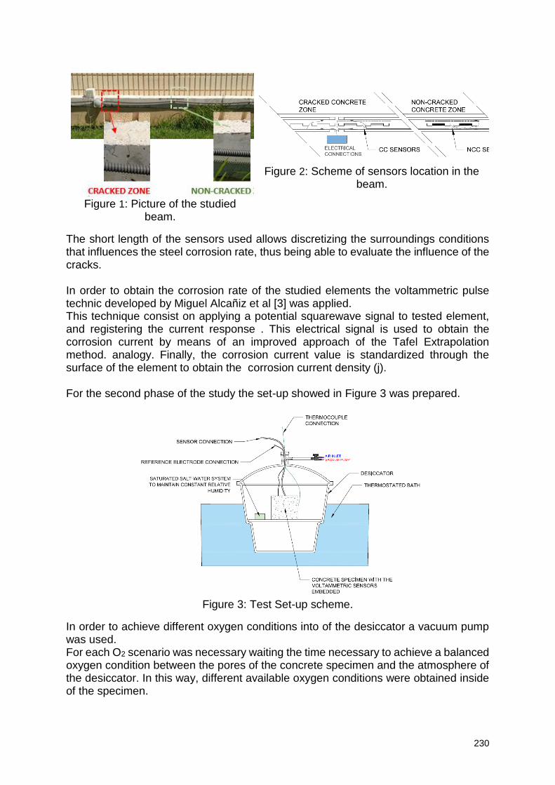
230
Figure 1: Picture of the studied
beam.
Figure 2: Scheme of sensors location in the
beam.
The short length of the sensors used allows discretizing the surroundings conditions that influences the steel corrosion rate, thus being able to evaluate the influence of the cracks. In order to obtain the corrosion rate of the studied elements the voltammetric pulse technic developed by Miguel Alcañiz et al [3] was applied. This technique consist on applying a potential squarewave signal to tested element, and registering the current response . This electrical signal is used to obtain the corrosion current by means of an improved approach of the Tafel Extrapolation method. analogy. Finally, the corrosion current value is standardized through the surface of the element to obtain the corrosion current density (j). For the second phase of the study the set-up showed in Figure 3 was prepared.
Figure 3: Test Set-up scheme.
In order to achieve different oxygen conditions into of the desiccator a vacuum pump was used. For each O2 scenario was necessary waiting the time necessary to achieve a balanced oxygen condition between the pores of the concrete specimen and the atmosphere of the desiccator. In this way, different available oxygen conditions were obtained inside of the specimen.
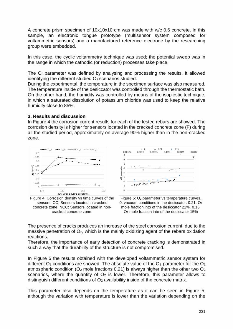
231
A concrete prism specimen of 10x10x10 cm was made with w/c 0.6 concrete. In this sample, an electronic tongue prototype (multisensor system composed for voltammetric sensors) and a manufactured reference electrode by the researching group were embedded. In this case, the cyclic voltammetry technique was used; the potential sweep was in the range in which the cathodic (or reduction) processes take place. The O2 parameter was defined by analysing and processing the results. It allowed identifying the different studied O2 scenarios studied. During the experimental, the temperature in the specimen surface was also measured. The temperature inside of the desiccator was controlled through the thermostatic bath. On the other hand, the humidity was controlled by means of the isopiestic technique, in which a saturated dissolution of potassium chloride was used to keep the relative humidity close to 85%. 3. Results and discussion In Figure 4 the corrosion current results for each of the tested rebars are showed. The corrosion density is higher for sensors located in the cracked concrete zone (F) during all the studied period, approximately on average 90% higher than in the non-cracked zone.
Figure 4: Corrosion density vs time curves of the
sensors. CC: Sensors located in cracked concrete zone. NCC: Sensors located in non-
cracked concrete zone.
Figure 5: O2 parameter vs temperature curves. 0: vacuum conditions in the desiccator. 0.21: O2 mole fraction into of the desiccator 21%. 0.15:
O2 mole fraction into of the desiccator 15%
The presence of cracks produces an increase of the steel corrosion current, due to the massive penetration of O2, which is the mainly oxidizing agent of the rebars oxidation reactions. Therefore, the importance of early detection of concrete cracking is demonstrated in such a way that the durability of the structure is not compromised. In Figure 5 the results obtained with the developed voltammetric sensor system for different O2 conditions are showed. The absolute value of the O2-parameter for the O2 atmospheric condition (O2 mole fractions 0.21) is always higher than the other two O2 scenarios, where the quantity of O2 is lower. Therefore, this parameter allows to distinguish different conditions of O2 availability inside of the concrete matrix.
This parameter also depends on the temperature as it can be seen in Figure 5, although the variation with temperature is lower than the variation depending on the
232
oxygen availability. In addition, this parameter will be less influenced by variables such as humidity or temperature than the current density, thus simplify the mathematical models necessary to isolate the variable of interest, in this case the oxygen availability. 4. Conclusion The use of voltammetric sensors, by applying the cyclic voltammetry technique in an appropriated potential range, allows to obtain a parameter associated with the oxygen availability in the surroundings of the sensor: the O2-parameter. The O2-parameter allows identifying oxygen variations, so it could be applied to identify cracks in the concrete matrix at an early age without compromising the structural safety of the construction. Acknowledgements The authors would like to express their gratitude to the Spanish Ministry of Science and Innovation for the pre-doctoral scholarship granted to Ana Martínez Ibernón (FPU 13/00723). Also, to the Universitat Politècnica de València for the financial support in the project “Ayudas a Primeros Proyectos de Investigación (PAID-06-18)”. And also, Rafael Calabuig, Jesus Martínez and Manolo Calabuig, Laboratory technicians of The Escuela Técnica Superior de Ingeniería de Edificación of Universitat Politècnica de València, for their invaluable cooperation. References [1] Correia, M. J. et al. (2006) ‘Sensor for oxygen evaluation in concrete’, Cement and Concrete Composites, 28(3), pp. 226–232. doi: 10.1016/j.cemconcomp.2006.01.006. Gojkovic, S. L., Zecevic, S. K. and Drazic, D. M. (1994) ‘Oxygen reduction on iron-Part VI. Processes in alkaline solutions’, Electrochimica Acta, 39(7), pp. 975–982. doi: 10.1016/0013-4686(94)85115-8. [2] McCarter, W. J. and Vennesland, Ø. (2004) ‘Sensor systems for use in reinforced concrete structures’, Construction and Building Materials, 18(6), pp. 351–358. doi: 10.1016/j.conbuildmat.2004.03.008. [3] Alcañiz M., Bataller R., Gandía-Romero J.M, Ramón J.E., Soto J., Valcuende M., Universidad Politécnica de Valencia, “Sensor, red de sensores, método y programa informático para determinar la corrosión en una estructura de hormigón armado”, nºES2545669 (Patente de Invención concedida con Examen Previo) mayo 06, 2015.
233
Chlorides penetration forecast by means of ionic resistance value
A. Martínez Ibernón1, J.R. Lliso Ferrando1, R. Calabuig2, M. Valcuende2
1 IDM - Instituto Interuniversitario de Reconocimiento Molecular y Desarrollo Tecnológico. Dpto. de Química. ETSIE. Universitat Politècnica de València, Camino de Vera s/n, 46022 Valencia, España. E-mail: [email protected] 2 Departamento de construcciones arquitectonicas. Universitat Politècnica de València, Camino de Vera s/n, 46022 Valencia, España.
Abstract Diffusion chloride techniques are very effective for the study of chloride’s penetration resistance in the concrete matrix. In addition, these techniques can be used in conjunction with other techniques that allow obtaining the percentage of chlorides, being able to stablish comparisons between the results in different concretes. However, this kind of techniques take a lot of time in order to obtain desirable results. Conversely, techniques as the described in NT BUILD 492 accelerates the penetration of chloride in concrete matrix through the migration effect. With this technique the non-steady-state migration coefficient is obtained, it is not the effective coefficient of diffusion, but it provides an idea of how easy or difficult the penetration of chlorides will be in a concrete matrix. In this research the accelerated chlorides penetration technique was applied in the same potential conditions regardless of the concrete type in order to get a comparable free chloride percentage between different specimens. In a future step, these results will be compared with the results of the diffusion test, in order to stablish a correlation to study the natural phenomenon of chlorides penetration through accelerated migration test. 1. Introduction Chlorides attack produces a local destruction of the steel passive layer in reinforced concrete structures. When moisture and temperature conditions are favorable a quickly pitting corrosion of the rebar occurs. The strong anodic character of the pitting produces an intense macrocell effect, which considerably increase the section loss of reinforced bars as is shown in the bibliography [1]. Therefore, the study of chlorides penetration in reinforced concretes is very important to monitor their durability. Diffusion chloride techniques as described in NT BUILD 443 or CEN/TS 12390-11, are very effective to study of the chloride penetration resistance in a concrete matrix. In addition, if these techniques are used in conjunction with the process explained in RILEM TC 178-TMC to obtain the quantity of free chlorides in the concrete matrix, it will be very effective in order to analyse the behaviour of the flowing chlorides inside a concrete matrix. However, the techniques based on diffusion chlorides penetration takes a lot of time in order to get the desirable results. Conversely, techniques as the described in NT BUILD 492 accelerates the penetration of chloride in concrete matrix through the migration effect. With this technique the non-steady-state migration coefficient is obtained, it is not the effective coefficient of diffusion, but it provides an idea of how easy or difficult the penetration of chlorides will be in a concrete matrix However, in this technique depending on the initial current, a fixed voltage is applied between the faces of the concrete specimen (time and the applied voltage can be adjusted). This means that different concretes, with different electric resistance, will be
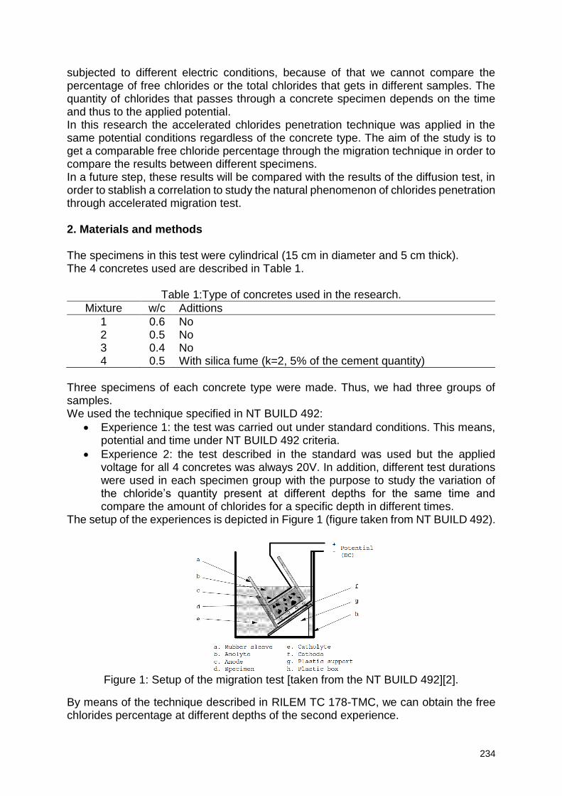
234
subjected to different electric conditions, because of that we cannot compare the percentage of free chlorides or the total chlorides that gets in different samples. The quantity of chlorides that passes through a concrete specimen depends on the time and thus to the applied potential. In this research the accelerated chlorides penetration technique was applied in the same potential conditions regardless of the concrete type. The aim of the study is to get a comparable free chloride percentage through the migration technique in order to compare the results between different specimens. In a future step, these results will be compared with the results of the diffusion test, in order to stablish a correlation to study the natural phenomenon of chlorides penetration through accelerated migration test. 2. Materials and methods The specimens in this test were cylindrical (15 cm in diameter and 5 cm thick). The 4 concretes used are described in Table 1.
Table 1:Type of concretes used in the research.
Mixture w/c Adittions
1 0.6 No 2 0.5 No 3 0.4 No 4 0.5 With silica fume (k=2, 5% of the cement quantity)
Three specimens of each concrete type were made. Thus, we had three groups of samples. We used the technique specified in NT BUILD 492:
Experience 1: the test was carried out under standard conditions. This means, potential and time under NT BUILD 492 criteria.
Experience 2: the test described in the standard was used but the applied voltage for all 4 concretes was always 20V. In addition, different test durations were used in each specimen group with the purpose to study the variation of the chloride’s quantity present at different depths for the same time and compare the amount of chlorides for a specific depth in different times.
The setup of the experiences is depicted in Figure 1 (figure taken from NT BUILD 492).
Figure 1: Setup of the migration test [taken from the NT BUILD 492][2].
By means of the technique described in RILEM TC 178-TMC, we can obtain the free chlorides percentage at different depths of the second experience.
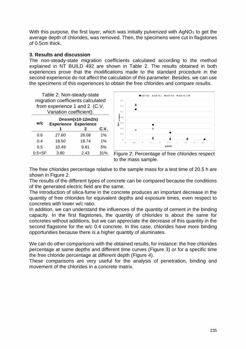
235
With this purpose, the first layer, which was initially pulverized with AgNO3 to get the average depth of chlorides, was removed. Then, the specimens were cut in flagstones of 0.5cm thick. 3. Results and discussion The non-steady-state migration coefficients calculated according to the method explained in NT BUILD 492 are shown in Table 2. The results obtained in both experiences prove that the modifications made to the standard procedure in the second experience do not affect the calculation of this parameter. Besides, we can use the specimens of this experiences to obtain the free chlorides and compare results.
Table 2: Non-steady-state migration coefficients calculated from experience 1 and 2. (C.V.
Variation coefficient).
w/c Dnssm(x10-12m2/s)
Experience 1
Experience 2 C.V.
0.6 27.60 28.08 1%
0.4 18.50 18.74 1%
0.5 10.49 9.81 5%
0.5+SF 3.80 2.43 31%
Figure 2: Percentage of free chlorides respect to the mass sample.
The free chlorides percentage relative to the sample mass for a test time of 20.5 h are shown in Figure 2. The results of the different types of concrete can be compared because the conditions of the generated electric field are the same. The introduction of silica-fume in the concrete produces an important decrease in the quantity of free chlorides for equivalent depths and exposure times, even respect to concretes with lower w/c ratio. In addition, we can understand the influences of the quantity of cement in the binding capacity. In the first flagstones, the quantity of chlorides is about the same for concretes without additions, but we can appreciate the decrease of this quantity in the second flagstone for the w/c 0.4 concrete. In this case, chlorides have more binding opportunities because there is a higher quantity of aluminates. We can do other comparisons with the obtained results, for instance: the free chlorides percentage at same depths and different time curves (Figure 3) or for a specific time the free chloride percentage at different depth (Figure 4). These comparisons are very useful for the analysis of penetration, binding and movement of the chlorides in a concrete matrix.
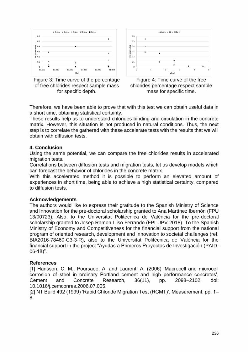
236
Figure 3: Time curve of the percentage of free chlorides respect sample mass
for specific depth.
Figure 4: Time curve of the free
chlorides percentage respect sample mass for specific time.
Therefore, we have been able to prove that with this test we can obtain useful data in a short time, obtaining statistical certainty. These results help us to understand chlorides binding and circulation in the concrete matrix. However, this situation is not produced in natural conditions. Thus, the next step is to correlate the gathered with these accelerate tests with the results that we will obtain with diffusion tests. 4. Conclusion Using the same potential, we can compare the free chlorides results in accelerated migration tests. Correlations between diffusion tests and migration tests, let us develop models which can forecast the behavior of chlorides in the concrete matrix. With this accelerated method it is possible to perform an elevated amount of experiences in short time, being able to achieve a high statistical certainty, compared to diffusion tests. Acknowledgements The authors would like to express their gratitude to the Spanish Ministry of Science and Innovation for the pre-doctoral scholarship granted to Ana Martínez Ibernón (FPU 13/00723). Also, to the Universitat Politècnica de València for the pre-doctoral scholarship granted to Josep Ramon Lliso Ferrando (FPI-UPV-2018). To the Spanish Ministry of Economy and Competitiveness for the financial support from the national program of oriented research, development and Innovation to societal challenges (ref. BIA2016-78460-C3-3-R), also to the Universitat Politècnica de València for the financial support in the project “Ayudas a Primeros Proyectos de Investigación (PAID-06-18)”. References [1] Hansson, C. M., Poursaee, A. and Laurent, A. (2006) ‘Macrocell and microcell corrosion of steel in ordinary Portland cement and high performance concretes’, Cement and Concrete Research, 36(11), pp. 2098–2102. doi: 10.1016/j.cemconres.2006.07.005. [2] NT Build 492 (1999) ‘Rapid Chloride Migration Test (RCMT)’, Measurement, pp. 1–8.
237
Durability of reinforced concrete structures under simultaneous flexural load in corrosive environment
L. Karavokyros1, N. Katsiotis1, G. Batis1, M.S. Katsiotis2, E. Tzanis2, M.Beazi-Katsioti1
1 National Technical University of Athens, School of Chemical Engineering, Iroon Polytechneiou 9, 15780 NTUA Zografou Campus, Athens, Greece – email: [email protected] 2 Titan Cement Group, 22Α Ηalkidos Str, 111 43, Αthens, Greece – email: [email protected]
Abstract
In this study, the corrosion behavior of reinforcing steels in concrete under simultaneous flexural load and chlorides attack was studied. The influence of different stress ratios in marine environments on corrosion resistance of steels was analyzed. For this purpose 40 reinforced concrete beams were constructed, exposed in different environmental conditions and their behavior against corrosion was studied with the use of electrochemical methods. The compositions were developed according to the limits set by the latest concrete technology regulations and International Standards; these were: C30 /37 conventional concrete, concrete C30/37 with corrosion inhibitor as additive, C30/37 with surface spray sealant, fine aggregate concrete and self-compacting concrete. Keywords: Steel reinforced concrete, Corrosion resistance, Flexural load, Marine Structures, Chlorides 1. Introduction
In recent years, there have been intense problems of unsatisfactory results in structural durability, with corrosion of reinforcement being the most important problem in reinforced concrete structures. The chloride-induced steel corrosion in reinforced concrete structures (RCS) is of major concern in marine environments [1,2].In general, the high alkalinity of concrete pore solutions leads to protective passive film on steel surface which delays the time to corrosion initiation. However, when the content of chloride ions at the steel-concrete interface reach the chloride threshold level, steel starts to corrode, and corrosion products are generated gradually on the steel surface, ultimately leading to premature cracking and spalling of RCSs [1,3]. To date, many studies have been performed to investigate the corrosion behavior of steel in simulated concrete pore solutions and RCSs in aggressive environments [4-6]. However, little attention has been given to the influence of external load on the corrosion behavior of steels in concrete. The most vulnerable area of a marine construction is that of the splash or the tidal zone which is subject to alternating wetting and drying cycles and is the one that is considered in this study (exposure categories XS1,XS3)[3]. In effect, it is a well-known fact that RCSs are usually subjected to various types of external loads (compression, tension and flexure, etc.) during the long-term service process [7,8]. Among them, the flexural load is the most common and important load type. Generally, the flexural load exerts influence on three typical processes in the service life of RCSs in marine environments: the passivation stage of steel, the corrosion initiation stage and the corrosion propagation stage. This research aims to estimate the effect of the permanent loading and the composition (grading, additives, admixtures) of a concrete structure on its durability against harmful environmental conditions.
238
2. Materials and Methods
For the experimental part reinforced concrete beams were constructed and studied in corrosive conditions with simultaneous flexural load. Specifically, 40 concrete beam specimens with the size of 15cm x 25 cm x 150cm were constructed and their behavior was studied for over three years. Four (4) deformed low-carbon reinforcing steel bars with a diameter of 12mm were embedded in the 4 corners of the specimen’s cross section. The steel bars were used in as-received condition without any modification of the surface and the chemical composition (wt%) of steel was 0.21C, 0.39Cu, 38Ceq, 0.022P, 0.028S. The concrete compositions were selected in accordance with the limitations set by the concrete technology regulations and are: concrete quality C30/37 (reference composition), C30/37 with additional corrosion inhibitor (4 wt% of cement), C30/37 with surface sprayed sealant, self-compacting concrete and fine aggregate concrete (Dmax < 16mm ). The conditions in which the beam specimens were tested were: exposed to the natural environment (reference specimens), simulated marine environment (regular surface spray with 4 wt% NaCl solution), first stress ratio in simulated marine environment, second stress ratio in simulated marine environment. The samples were produced in a ready mix concrete plant, the beam molds were created exclusively for the experimental process and were designed based on standard concrete beams. The desired loads have been achieved by using reinforced concrete blocks (850kg/block) which were mounted in the middle of the beams. In addition, tests were made to evaluate the quality of the formulations produced (compressive strength at 7,14,28 days) and for the fresh phase properties (slump test, spread test, temperature). Over three years, the corrosion potential of the steel-reinforcement and the electric resistance of the concrete were evaluated. Accelerating penetration of chlorides into the interior of the beams was achieved by regular surface spraying with a 4% sodium chloride solution. 3. Results and discussion
Electrochemical methods for corrosion assessment are based on its electrochemical nature and measure the electrical properties of the electrically conductive bilayer (steel-solution interface) for the investigation of the corrosion mechanism and for its monitoring and control [1,2]. Tests of the electrical resistance of the concrete were carried out by the arrangement of four Wenner electrodes (according to ASTM G57) and the corrosion potential of the steel reinforcement was conducted using a copper sulphate as a reference electrode (according to ASTM C876) [9]. The following graphs (Figure 1a,b) show the evolution of the electric resistance of concrete and the corrosion potential of the reinforcement steels. The results from the following diagrams and from the overall data are then analyzed and discussed.
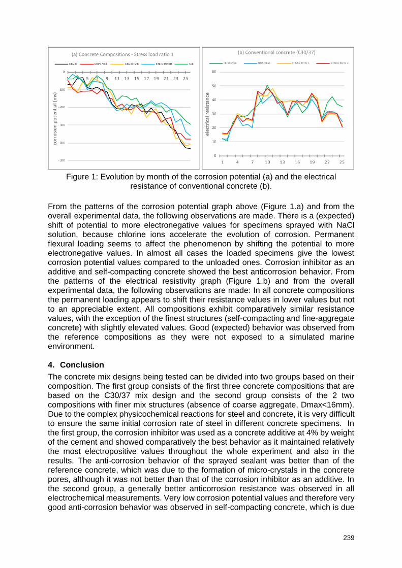
239
Figure 1: Evolution by month of the corrosion potential (a) and the electrical resistance of conventional concrete (b).
From the patterns of the corrosion potential graph above (Figure 1.a) and from the overall experimental data, the following observations are made. There is a (expected) shift of potential to more electronegative values for specimens sprayed with NaCl solution, because chlorine ions accelerate the evolution of corrosion. Permanent flexural loading seems to affect the phenomenon by shifting the potential to more electronegative values. In almost all cases the loaded specimens give the lowest corrosion potential values compared to the unloaded ones. Corrosion inhibitor as an additive and self-compacting concrete showed the best anticorrosion behavior. From the patterns of the electrical resistivity graph (Figure 1.b) and from the overall experimental data, the following observations are made: In all concrete compositions the permanent loading appears to shift their resistance values in lower values but not to an appreciable extent. All compositions exhibit comparatively similar resistance values, with the exception of the finest structures (self-compacting and fine-aggregate concrete) with slightly elevated values. Good (expected) behavior was observed from the reference compositions as they were not exposed to a simulated marine environment. 4. Conclusion
The concrete mix designs being tested can be divided into two groups based on their composition. The first group consists of the first three concrete compositions that are based on the C30/37 mix design and the second group consists of the 2 two compositions with finer mix structures (absence of coarse aggregate, Dmax<16mm). Due to the complex physicochemical reactions for steel and concrete, it is very difficult to ensure the same initial corrosion rate of steel in different concrete specimens. In the first group, the corrosion inhibitor was used as a concrete additive at 4% by weight of the cement and showed comparatively the best behavior as it maintained relatively the most electropositive values throughout the whole experiment and also in the results. The anti-corrosion behavior of the sprayed sealant was better than of the reference concrete, which was due to the formation of micro-crystals in the concrete pores, although it was not better than that of the corrosion inhibitor as an additive. In the second group, a generally better anticorrosion resistance was observed in all electrochemical measurements. Very low corrosion potential values and therefore very good anti-corrosion behavior was observed in self-compacting concrete, which is due
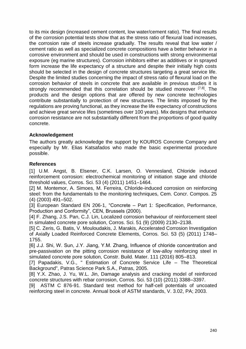
240
to its mix design (increased cement content, low water/cement ratio). The final results of the corrosion potential tests show that as the stress ratio of flexural load increases, the corrosion rate of steels increase gradually. The results reveal that low water / cement ratio as well as specialized concrete compositions have a better behavior in a corrosive environment and should be used in constructions with strong environmental exposure (eg marine structures). Corrosion inhibitors either as additives or in sprayed form increase the life expectancy of a structure and despite their initially high costs should be selected in the design of concrete structures targeting a great service life. Despite the limited studies concerning the impact of stress ratio of flexural load on the corrosion behavior of steels in concrete that are available in previous studies it is strongly recommended that this correlation should be studied moreover [7,8]. The products and the design options that are offered by new concrete technologies contribute substantially to protection of new structures. The limits imposed by the regulations are proving functional, as they increase the life expectancy of constructions and achieve great service lifes (sometimes over 100 years). Mix designs that enhance corrosion resistance are not substantially different from the proportions of good quality concrete. Acknowledgement
The authors greatly acknowledge the support by KOUROS Concrete Company and especially by Mr. Elias Katsafados who made the basic experimental procedure possible.
References
[1] U.M. Angst, B. Elsener, C.K. Larsen, O. Vennesland, Chloride induced reinforcement corrosion: electrochemical monitoring of initiation stage and chloride threshold values, Corros. Sci. 53 (4) (2011) 1451–1464. [2] M. Montemor, A. Simoes, M. Ferreira, Chloride-induced corrosion on reinforcing steel: from the fundamentals to the monitoring techniques, Cem. Concr. Compos. 25 (4) (2003) 491–502. [3] European Standard EN 206-1, “Concrete – Part 1: Specification, Performance, Production and Conformity”, CEN, Brussels (2000). [4] F. Zhang, J.S. Pan, C.J. Lin, Localized corrosion behaviour of reinforcement steel in simulated concrete pore solution, Corros. Sci. 51 (9) (2009) 2130–2138. [5] C. Zeris, G. Batis, V. Mouloudakis, J. Marakis, Accelerated Corrosion Investigation of Axially Loaded Reinforced Concrete Elements, Corros. Sci. 53 (5) (2011) 1748–1755. [6] J.J. Shi, W. Sun, J.Y. Jiang, Y.M. Zhang, Influence of chloride concentration and pre-passivation on the pitting corrosion resistance of low-alloy reinforcing steel in simulated concrete pore solution, Constr. Build. Mater. 111 (2016) 805–813. [7] Papadakis, V.G., " Estimation of Concrete Service Life – The Theoretical Background", Patras Science Park S.A., Patras, 2005. [8] Y.X. Zhao, J. Yu, W.L. Jin, Damage analysis and cracking model of reinforced concrete structures with rebar corrosion, Corros. Sci. 53 (10) (2011) 3388–3397. [9] ASTM C 876-91. Standard test method for half-cell potentials of uncoated reinforcing steel in concrete. Annual book of ASTM standards, V. 3.02, PA; 2003.
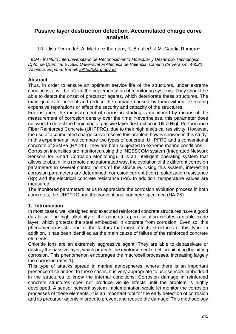
241
Passive layer destruction detection. Accumulated charge curve analysis.
J.R. Lliso Ferrando1, A. Martínez Ibernón1, R. Bataller1, J.M. Gandia Romero1
1 IDM - Instituto Interuniversitario de Reconocimiento Molecular y Desarrollo Tecnológico. Dpto. de Química. ETSIE. Universitat Politècnica de València, Camino de Vera s/n, 46022 Valencia, España. E-mail: [email protected]
Abstract Thus, in order to ensure an optimum service life of the structures, under extreme conditions, it will be useful the implementation of monitoring systems. They should be able to detect the onset of precursor agents, which deteriorate these structures. The main goal is to prevent and reduce the damage caused by them without executing expensive reparations or affect the security and capacity of the structures. For instance, the measurement of corrosion starting is monitored by means of the measurement of corrosion density over the time. Nevertheless, this parameter does not work to detect the beginning of passive layer destruction in Ultra High Performance Fiber Reinforced Concrete (UHPFRC), due to their high electrical resistivity. However, the use of accumulated charge curve resolve this problem how is showed in this study. In this experimental, we compare two types of concrete: UHPFRC and a conventional concrete of 25MPa (HA-25). They are both subjected to extreme marine conditions. Corrosion intensities are monitored using the INESSCOM system (Integrated Network Sensors for Smart Corrosion Monitoring). It is an intelligent operating system that allows to obtain, in a remote and automated way, the evolution of the different corrosion parameters in several control points of the structure. Using this system, interesting corrosion parameters are determined: corrosion current (icorr), polarization resistance (Rp) and the electrical concrete resistance (Rs). In addition, temperature values are measured. The monitored parameters let us to appreciate the corrosion evolution process in both concretes, the UHPFRC and the conventional concrete specimen (HA-25). 1. Introduction In most cases, well-designed and executed reinforced concrete structures have a good durability. The high alkalinity of the concrete’s pore solution creates a stable oxide layer, which protects the steel embedded in concrete from corrosion. Even so, this phenomenon is still one of the factors that most affects structures of this type. In addition, it has been identified as the main cause of failure of the reinforced concrete elements. Chloride ions are an extremely aggressive agent. They are able to depassivate or destroy the passive layer, which protects the reinforcement steel, propitiating the pitting corrosion. This phenomenon encourages the macrocell processes, increasing largely the corrosion rates[1]. This type of attacks spread in marine atmospheres, where there is an important presence of chlorides. In these cases, it is very appropriate to use sensors embedded in the structures to know the internal conditions. Corrosion damage in reinforced concrete structures does not produce visible effects until the problem is highly developed. A sensor network system implementation would let monitor the corrosion processes of these elements. It is an important tool for the early detection of corrosion and its precursor agents in order to prevent and reduce the damage. This methodology
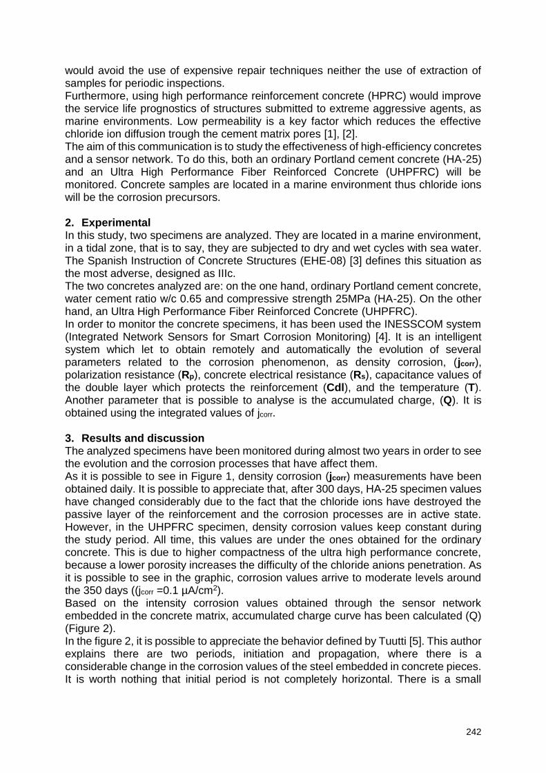
242
would avoid the use of expensive repair techniques neither the use of extraction of samples for periodic inspections. Furthermore, using high performance reinforcement concrete (HPRC) would improve the service life prognostics of structures submitted to extreme aggressive agents, as marine environments. Low permeability is a key factor which reduces the effective chloride ion diffusion trough the cement matrix pores [1], [2]. The aim of this communication is to study the effectiveness of high-efficiency concretes and a sensor network. To do this, both an ordinary Portland cement concrete (HA-25) and an Ultra High Performance Fiber Reinforced Concrete (UHPFRC) will be monitored. Concrete samples are located in a marine environment thus chloride ions will be the corrosion precursors. 2. Experimental In this study, two specimens are analyzed. They are located in a marine environment, in a tidal zone, that is to say, they are subjected to dry and wet cycles with sea water. The Spanish Instruction of Concrete Structures (EHE-08) [3] defines this situation as the most adverse, designed as IIIc. The two concretes analyzed are: on the one hand, ordinary Portland cement concrete, water cement ratio w/c 0.65 and compressive strength 25MPa (HA-25). On the other hand, an Ultra High Performance Fiber Reinforced Concrete (UHPFRC). In order to monitor the concrete specimens, it has been used the INESSCOM system (Integrated Network Sensors for Smart Corrosion Monitoring) [4]. It is an intelligent system which let to obtain remotely and automatically the evolution of several parameters related to the corrosion phenomenon, as density corrosion, (jcorr), polarization resistance (Rp), concrete electrical resistance (Rs), capacitance values of the double layer which protects the reinforcement (Cdl), and the temperature (T). Another parameter that is possible to analyse is the accumulated charge, (Q). It is obtained using the integrated values of jcorr. 3. Results and discussion The analyzed specimens have been monitored during almost two years in order to see the evolution and the corrosion processes that have affect them. As it is possible to see in Figure 1, density corrosion (jcorr) measurements have been obtained daily. It is possible to appreciate that, after 300 days, HA-25 specimen values have changed considerably due to the fact that the chloride ions have destroyed the passive layer of the reinforcement and the corrosion processes are in active state. However, in the UHPFRC specimen, density corrosion values keep constant during the study period. All time, this values are under the ones obtained for the ordinary concrete. This is due to higher compactness of the ultra high performance concrete, because a lower porosity increases the difficulty of the chloride anions penetration. As it is possible to see in the graphic, corrosion values arrive to moderate levels around the 350 days ((jcorr =0.1 µA/cm2). Based on the intensity corrosion values obtained through the sensor network embedded in the concrete matrix, accumulated charge curve has been calculated (Q) (Figure 2). In the figure 2, it is possible to appreciate the behavior defined by Tuutti [5]. This author explains there are two periods, initiation and propagation, where there is a considerable change in the corrosion values of the steel embedded in concrete pieces. It is worth nothing that initial period is not completely horizontal. There is a small
243
increment that changes when passive layer is destroyed and corrosion processes are active. As it is shown in the graphic, initiation period is around the 200 days.
Figure 1: Density corrosion evolution.
Figure 2: Accumulated charge curve.
The analysis of the accumulated charge allows to detect the corrosion beginning before this phenomenon reaches dangerous values. Figure 1 shows density corrosion values analysis (jcorr). It is possible to appreciate an important dispersion, and lecture of high values might be misleading. In contrast, accumulated charge curve analysis, as it is an accumulated value, there is no dispersion, and the slope changes show the initiation and propagation steps of the corrosion processes. Another value it should be taken into account is the prediction and analysis of the service life of reinforced concrete structures. There are several methods to evaluate the estimated lifespan, as the Bazant, Wang and Zao, Morinaga or Daghler and Kulendran methods [6]. The EHE-08 [3] presents several expressions to quantify the service life of the concrete structures according to the ambient where they are located and the characteristics of the materials. In this study, it has been calculated the time chloride ions need to arrive to the reinforcement pieces. For that purpose, it has been used the method defined in the NT-BUILD 443 [7] normative. These expressions are based in the Fick Second Diffusion Law:
244
If the time is isolated, it is possible to calculate the initiation period time (in years). The necessary data have been extracted from the characterization of the material in lab and the EHE-08 [3]. Using the previously mathematical expressions, we can conclude that initial corrosion period for the HA-25 specimen is about one year (1,39 years). This value corresponds to the evolution showed in Figure 1. However, initial period time for the UHPFRC specimen is estimated beyond 1400 years. 4. Conclusion In this study it has been tested the effectiveness of installing sensors for the analysis of the corrosion processes developed inside the reinforced concrete pieces. In this case it has been proved the reliability of the INESSCOM system, able to detect different parameters in both ordinary and high performance concretes. Also it is possible to appreciate a better performance in the UHPFRC specimen versus an ordinary Portland cement concrete (HA-25). Lower mechanical capacity specimen suffers active corrosion in one year. Instead, high performance concrete specimen would be able to arrive to the 1400 years without being affected by active corrosion processes. In addition, it has been possible to prove the effectiveness of the accumulated charge curve analysis to detect corrosion processes beforehand. Around the 200 days, an initial slope is appreciated for the initiation period. Close to 325 days, it is possible to appreciate the propagation period beginning. In the density corrosion analysis (Figure 1), values are more disperse and the analysis does not allow to detect the corrosion processes in advance. Thus, accumulated charge analysis would enable to detect corrosion processes in anticipation. It would help to raise repair works over the damaged structures previously to present a severe damage. Acknowledgements The authors would like to express their gratitude to the Universitat Politècnica de València for the pre-doctoral scholarship granted to Josep Ramon Lliso Ferrando (FPI-UPV-2018), and to the Spanish Ministry of Science and Innovation for the pre-doctoral scholarship granted to Ana Martínez Ibernón (FPU 13/00723). To the Spanish Ministry of Economy and Competitiveness for the financial support from the national program of oriented research, development and Innovation to societal challenges (ref. BIA2016-78460-C3-3-R). Also to Formex for concrete manufacturing and support. References [1] K. Y. Ann and H. W. Song, “Chloride threshold level for corrosion of steel in concrete,” Corros. Sci., vol. 49, no. 11, pp. 4113–4133, 2007. [2] J. E. Ramón, J. M. Gandía-Romero, M. Valcuende, and R. Bataller, “Integrated sensor network for monitoring steel corrosion in concrete structures,” Vitr. - Int. J. Archit. Technol. Sustain., vol. 1, no. 1, p. 65, 2016. [3] C. P. del Hormigón, “Instrucción del hormigón estructural EHE-08". [4] J. E. Ramon Zamora, “Sistema de Sensores Embebidos para Monitorizar la Corrosión en Estructuras de Hormigón Armado . Fundamentos , Metodología y Aplicaciones,” 2018. [5] J. P. Broomfield, “Corrosion of Steel in Concrete,” Uhlig’s Corros. Handb. Third Ed., pp. 633–647, 2011. [6] S. Ahmad, “Reinforcement corrosion in concrete structures, its monitoring and
245
service life prediction - A review,” Cem. Concr. Compos., vol. 25, no. 4–5 SPEC, pp. 459–471, 2003. [7] NT Build 492, “Rapid Chloride Migration Test (RCMT).
246
Chloride binding capacity and chloride diffusion coefficient of Portland cement mortar blended with high alumina cement and
calcium carbonate
Y. Lee 1, Z. Chen1, S. Lim2, and H. Lee1
1 Department of Architectural Engineering, Hanyang University, 55 Hanyangdaehak-ro, Sangnok-gu, Ansan-si, Gyeonggi-do, 15588, Republic of Korea – email: [email protected]; [email protected]; [email protected] 2 Innovative Durable Building and Infrastructure Research Center, Hanyang University, 55 Hanyangdaehak-ro, Sangnok-gu, Ansan-si, Gyeonggi-do, 15588, Republic of Korea – [email protected]
Abstract A pore characteristics and chloride binding capacity of binders are important factor for chloride resistant materials. A chemical composition and hydration kinetics can influence on the chloride resistance. This study investigates the chloride binding capacity and diffusion properties of Portland cement-based mortar blended with high alumina cement and calcium carbonate. The chloride binding capacity is evaluated using the cement paste and the chloride diffusion coefficient is calculated using the mortar according to NT Build 492 method. The results show that the high alumina content induce the high chloride binding capacity, but the hydration kinetics may have a negative effect on pore distribution. Keywords: chloride resistance, Portland cement, calcium aluminate, calcium carbonate 1. Introduction A binding of chloride ion in the marine concrete structures can suppress the chloride content in the pore solution and thereby contribute the increase of service life of the structures. The binding of chloride ion is dependent on the cement hydrates which consist of the structures of layered double hydroxides. The widely used supplementary cement materials such as the ground granulated blast-furnace slag, fly ash, metakaolin or a variety of natural pozzolan materials generally have a higher Al2O3 content than ordinary Portland cement (OPC). The increase of available Al2O3 in OPC system can induce the formation of AFm (Aluminoferrite mono-substituted) phases which are composed of layered double hydroxides. For this reason, the partial replacement of OPC with the materials containing high Al2O3 content can induce the high chloride binding capacity of OPC based system. But the pore structure can in no way be negligible as well as the chloride binding capacity for the chloride resistance. Since various materials have the different hydration kinetics and chemical compositions, and thus, they can influence on both the cement hydrates [1] and pore structure [1, 2] in the OPC-based system. This study investigates the chloride binding capacity and diffusion properties of OPC-based mortar blended with the high aluminate cement (HAC) as the alumina-rich material and calcium carbonate (CaCO3). The CaCO3 can accelerate the OPC setting, especially in case of high Al2O3 content, by inducing formulation of carbonate-bearing alumina phases and by the action like a nucleation seed [3]. Thus, we report our findings on the chloride resistance properties of the OPC-based mortar blended with HAC and CaCO3 considering the chloride binding capacity and pore distribution.
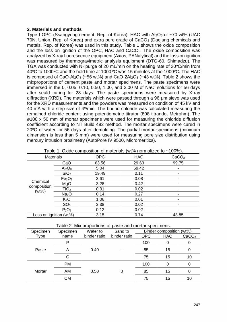
247
2. Materials and methods Type I OPC (Ssangyong cement, Rep. of Korea), HAC with Al2O3 of ~70 wt% (UAC 70N, Union, Rep. of Korea) and extra pure grade of CaCO3 (Daejung chemicals and metals, Rep. of Korea) was used in this study. Table 1 shows the oxide composition and the loss on ignition of the OPC, HAC and CaCO3. The oxide composition was analyzed by X-ray fluorescence equipment (Axios, PANalytical) and the loss on ignition was measured by thermogravimetric analysis equipment (DTG-60, Shimadzu). The TGA was conducted with N2 purge of 20 mL/min on the heating rate of 20oC/min from 40oC to 1000oC and the hold time at 1000 oC was 15 minutes at the 1000oC. The HAC is composed of CaO·Al2O3 (~56 wt%) and CaO·2Al2O3 (~43 wt%). Table 2 shows the mixproportions of cement paste and mortar specimens. The paste specimens were immersed in the 0, 0.05, 0.10, 0.50, 1.00, and 3.00 M of NaCl solutions for 56 days after seald curing for 28 days. The paste specimens were measured by X-ray diffraction (XRD). The materials which were passed through a 96 μm sieve was used for the XRD measurements and the powders was measured on condition of 45 kV and 40 mA with a step size of 4o/min. The bound chloride was calculated measuring the remained chloride content using potentiometric titrator (808 titrando, Metrohm). The ø100 x 50 mm of mortar specimens were used for measuring the chloride diffusion coefficient according to NT Build 492 method. The mortar specimens were cured in 20oC of water for 56 days after demolding. The partial mortar specimens (minimum dimension is less than 5 mm) were used for measuring pore size distribution using mercury intrusion prosimetry (AutoPore IV 9500, Micromeritics).
Table 1: Oxide composition of materials (wt% normalized to ~100%).
Materials OPC HAC CaCO3
Chemical composition
(wt%)
CaO 63.56 29.63 99.75
Al2O3 5.04 69.42 -
SiO2 19.49 0.11 -
Fe2O3 3.61 0.08 -
MgO 3.28 0.42 -
TiO2 0.31 0.02 -
Na2O 0.14 0.27 -
K2O 1.06 0.01 -
SO3 3.38 0.02 -
P2O5 0.12 0.02 -
Loss on ignition (wt%) 3.15 0.74 43.85
Table 2: Mix proportions of paste and mortar specimens.
Specimen Type
Specimen name
Water to binder ratio
Sand to binder ratio
Binder composition (wt%)
OPC HAC CaCO3
Paste
P
0.40 -
100 0 0
A 85 15 0
C 75 15 10
Mortar
PM
0.50 3
100 0 0
AM 85 15 0
CM 75 15 10
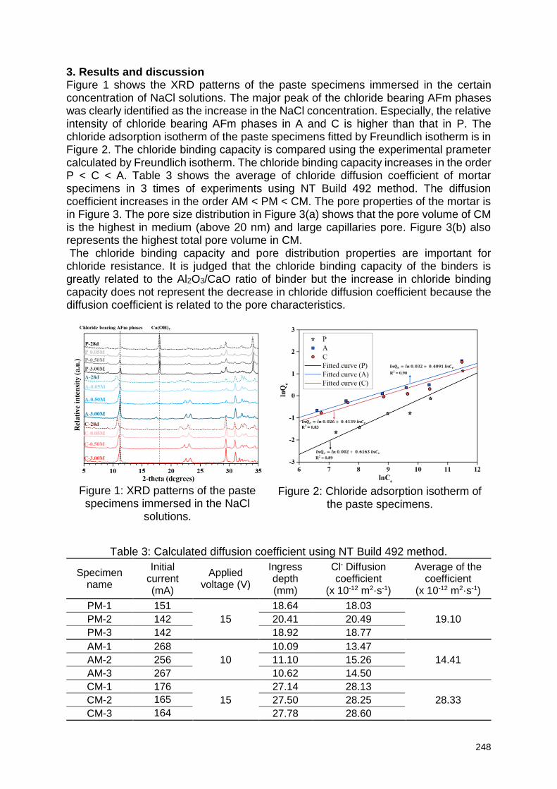
248
3. Results and discussion Figure 1 shows the XRD patterns of the paste specimens immersed in the certain concentration of NaCl solutions. The major peak of the chloride bearing AFm phases was clearly identified as the increase in the NaCl concentration. Especially, the relative intensity of chloride bearing AFm phases in A and C is higher than that in P. The chloride adsorption isotherm of the paste specimens fitted by Freundlich isotherm is in Figure 2. The chloride binding capacity is compared using the experimental prameter calculated by Freundlich isotherm. The chloride binding capacity increases in the order P < C < A. Table 3 shows the average of chloride diffusion coefficient of mortar specimens in 3 times of experiments using NT Build 492 method. The diffusion coefficient increases in the order AM < PM < CM. The pore properties of the mortar is in Figure 3. The pore size distribution in Figure 3(a) shows that the pore volume of CM is the highest in medium (above 20 nm) and large capillaries pore. Figure 3(b) also represents the highest total pore volume in CM. The chloride binding capacity and pore distribution properties are important for chloride resistance. It is judged that the chloride binding capacity of the binders is greatly related to the Al2O3/CaO ratio of binder but the increase in chloride binding capacity does not represent the decrease in chloride diffusion coefficient because the diffusion coefficient is related to the pore characteristics.
Figure 1: XRD patterns of the paste specimens immersed in the NaCl
solutions.
Figure 2: Chloride adsorption isotherm of the paste specimens.
Table 3: Calculated diffusion coefficient using NT Build 492 method.
Specimen name
Initial current (mA)
Applied voltage (V)
Ingress depth (mm)
Cl- Diffusion coefficient
(x 10-12 m2·s-1)
Average of the coefficient
(x 10-12 m2·s-1)
PM-1 151
15
18.64 18.03
19.10 PM-2 142 20.41 20.49
PM-3 142 18.92 18.77
AM-1 268
10
10.09 13.47
14.41 AM-2 256 11.10 15.26
AM-3 267 10.62 14.50
CM-1 176
15
27.14 28.13
28.33 CM-2 165 27.50 28.25
CM-3 164 27.78 28.60
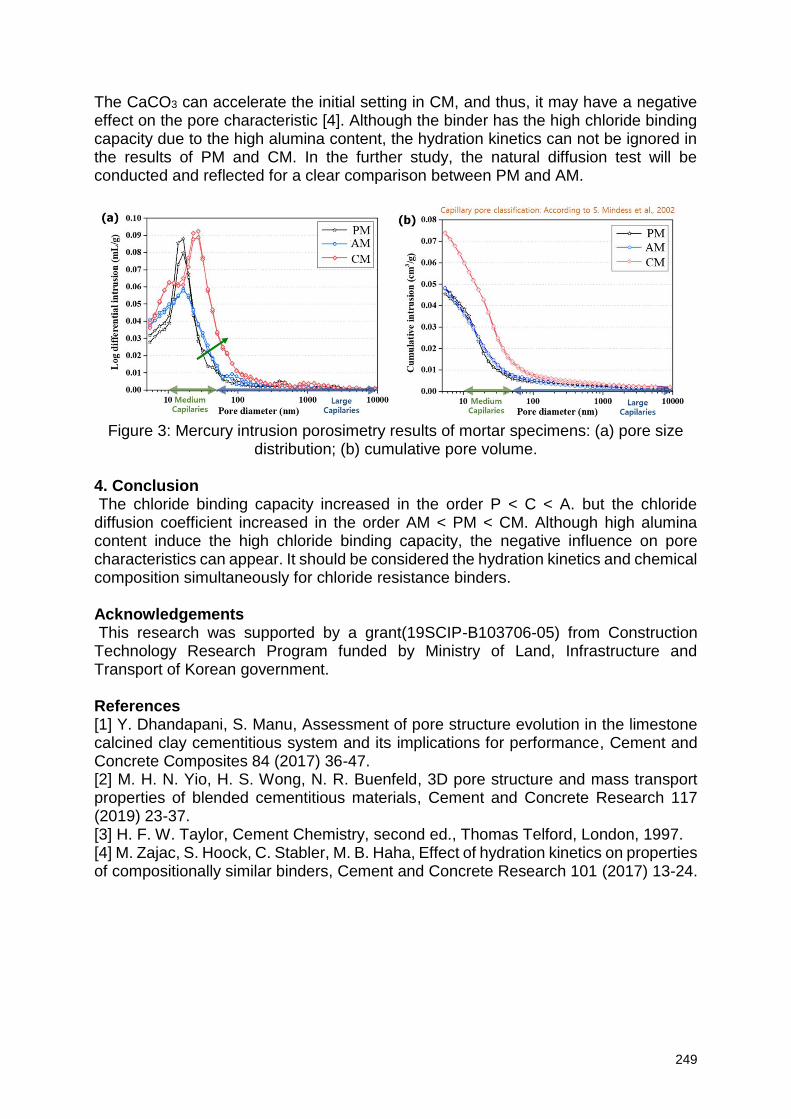
249
The CaCO3 can accelerate the initial setting in CM, and thus, it may have a negative effect on the pore characteristic [4]. Although the binder has the high chloride binding capacity due to the high alumina content, the hydration kinetics can not be ignored in the results of PM and CM. In the further study, the natural diffusion test will be conducted and reflected for a clear comparison between PM and AM.
Figure 3: Mercury intrusion porosimetry results of mortar specimens: (a) pore size
distribution; (b) cumulative pore volume. 4. Conclusion The chloride binding capacity increased in the order P < C < A. but the chloride diffusion coefficient increased in the order AM < PM < CM. Although high alumina content induce the high chloride binding capacity, the negative influence on pore characteristics can appear. It should be considered the hydration kinetics and chemical composition simultaneously for chloride resistance binders. Acknowledgements This research was supported by a grant(19SCIP-B103706-05) from Construction Technology Research Program funded by Ministry of Land, Infrastructure and Transport of Korean government. References [1] Y. Dhandapani, S. Manu, Assessment of pore structure evolution in the limestone calcined clay cementitious system and its implications for performance, Cement and Concrete Composites 84 (2017) 36-47. [2] M. H. N. Yio, H. S. Wong, N. R. Buenfeld, 3D pore structure and mass transport properties of blended cementitious materials, Cement and Concrete Research 117 (2019) 23-37. [3] H. F. W. Taylor, Cement Chemistry, second ed., Thomas Telford, London, 1997. [4] M. Zajac, S. Hoock, C. Stabler, M. B. Haha, Effect of hydration kinetics on properties of compositionally similar binders, Cement and Concrete Research 101 (2017) 13-24.
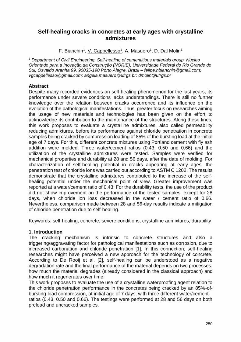
250
Self-healing cracks in concretes at early ages with crystalline admixtures
F. Bianchin1, V. Cappellesso1, A. Masuero1, D. Dal Molin1
1 Department of Civil Engineering, Self-healing of cementitious materials group, Núcleo Orientado para a Inovação da Construção (NORIE), Universidade Federal do Rio Grande do Sul, Osvaldo Aranha 99, 90035-190 Porto Alegre, Brazil – [email protected]; [email protected]; [email protected]; [email protected]
Abstract Despite many recorded evidences on self-healing phenomenon for the last years, its performance under severe conditions lacks understandings. There is still no further knowledge over the relation between cracks occurrence and its influence on the evolution of the pathological manifestations. Thus, greater focus on researches aiming the usage of new materials and technologies has been given on the effort to acknowledge its contribution to the maintenance of the structures. Along these lines, this work proposes to evaluate a crystalline admixtures, also called permeability reducing admixtures, before its performance against chloride penetration in concrete samples being cracked by compression loading of 85% of the bursting load at the initial age of 7 days. For this, different concrete mixtures using Portland cement with fly ash addition were molded. Three water/cement ratios (0.43, 0.50 and 0.66) and the utilization of the crystalline admixtures were tested. Samples were verified for mechanical properties and durability at 28 and 56 days, after the date of molding. For characterization of self-healing potential in cracks appearing at early ages, the penetration test of chloride ions was carried out according to ASTM C 1202. The results demonstrate that the crystalline admixtures contributed to the increase of the self-healing potential under the mechanical point of view. Greater improvement was reported at a water/cement ratio of 0.43. For the durability tests, the use of the product did not show improvement on the performance of the tested samples, except for 28 days, when chloride ion loss decreased in the water / cement ratio of 0.66. Nevertheless, comparison made between 28 and 56-day results indicate a mitigation of chloride penetration due to self-healing. Keywords: self-healing, concrete, severe conditions, crystalline admixtures, durability 1. Introduction The cracking mechanism is intrinsic to concrete structures and also a triggering/aggravating factor for pathological manifestations such as corrosion, due to increased carbonation and chloride penetration [1]. In this connection, self-healing researches might have perceived a new approach for the technology of concrete. According to De Rooij et al. [2], self-healing can be understood as a negative degradation rate and the final performance of the material depends on two processes: how much the material degrades (already considered in the classical approach) and how much it regenerates over time. This work proposes to evaluate the use of a crystalline waterproofing agent relation to the chloride penetration performance in the concretes being cracked by an 85%-of-bursting-load compression, at initial age of 7 days, with three different water/cement ratios (0.43, 0.50 and 0.66). The testings were performed at 28 and 56 days on both preload and uncracked samples.
251
2. Materials and methods 2.1 Materials 2.1.1 Cement and aggregates For the production of the concretes the following materials were used: a pozzolanic Portland cement with a compressive strength of 32 MPa (CP IV-32, ABNT NBR 5736:1990 - like Type IP, ASTM C 595) was used, with a specific mass of 2.78 g/cm³; a quartz sand as fine aggregate, fineness modulus equals to 1.94, maximum dimension of 2.4mm, specific mass of 2.64 g/cm³ and water absorption of 1.70% ; and basaltic coarse aggregate, fineness modulus of 7.02, maximum dimension of 19mm, specific dry aggregate mass of 2.95 g/cm³ and water absorption of 1.11% 2.1.2 Crystalline admixture The product used as crystalline waterproofing admixture is composed of Portland cement (40% to 70%), quartz sand (5% to 10%) and active chemical compounds (10% to 30%), as stated in the product data sheet. This product promotes chemical reactions in the presence of moisture which, along with the products of cement hydration, result in an insoluble crystalline structure capable of filling the capillary pores of the concrete. The product is an odorless gray powder, pH in solution between 10 and 13, specific mass of 2.92 g/cm³, and recommended dosage ranging from 0.8% to 1% on the mass of the cement. The concretes of this research were provided as following: Table 1: Unit consumption of materials expressed in kg/m3, and relative consumption in
comparison to the mass of cement in parenthesis (kg/kg)
2.2. Methods The uniaxial compressive strength of the samples was determined according to Brazilian standard NBR 5739:2007 [3]. The chloride ion penetration test on the concretes was constructed according to the standards test method by the American Standard ASTM C 1202:2012 [4].
3. Results and discussion In the result graphs the concretes were denominated with the letter N for those without the crystalline waterproofing admixture and P with the admixture. The letter F refers to cracked concrete. Numbers 1, 2 and 3 refer to water/cement ratios 0.43, 0.50 and 0.65, respectively. 3.1 Compressive strength From the results obtained (Figure 1) it is possible to verify, at day 56, greater increase in compressive strength in the preloaded samples to those corresponding uncracked for traces with water/binder ratios 0.43. It was also possible to note a more expressive increase of resistance in concrete containing crystalline admixture. Samples with water/cement ratio of 0.43 showed an increase of 11.4% in conventional concretes at
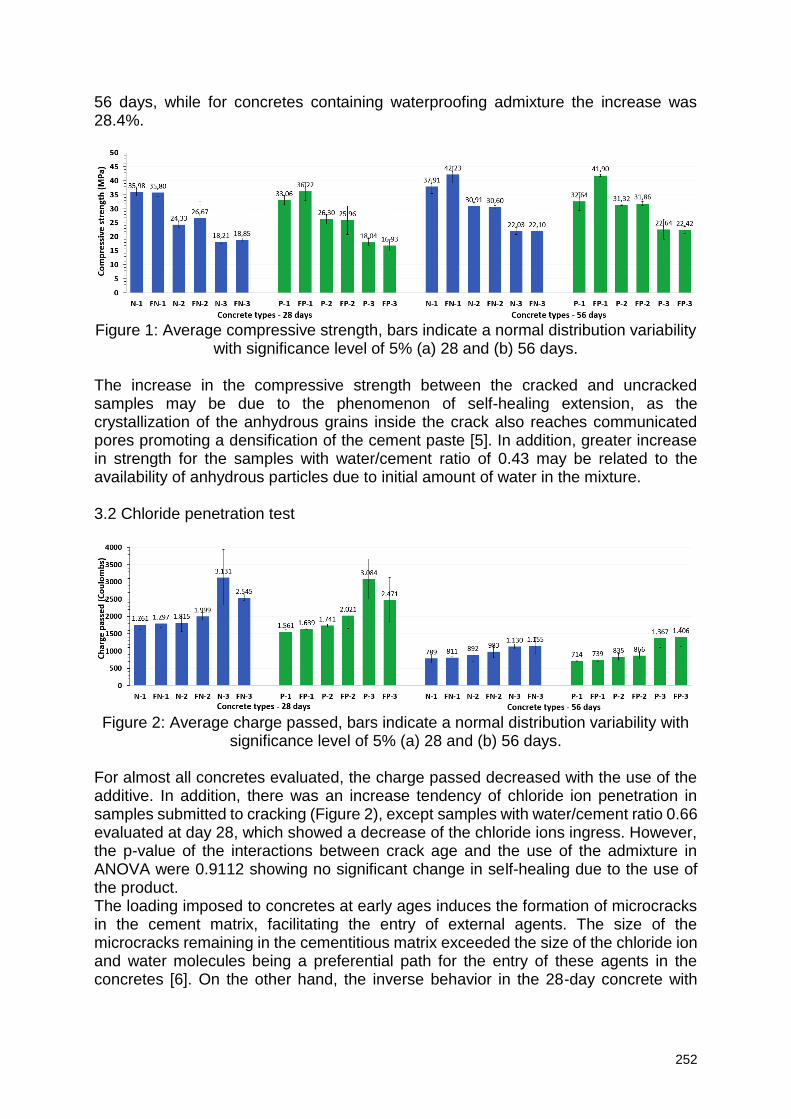
252
56 days, while for concretes containing waterproofing admixture the increase was 28.4%.
Figure 1: Average compressive strength, bars indicate a normal distribution variability
with significance level of 5% (a) 28 and (b) 56 days. The increase in the compressive strength between the cracked and uncracked samples may be due to the phenomenon of self-healing extension, as the crystallization of the anhydrous grains inside the crack also reaches communicated pores promoting a densification of the cement paste [5]. In addition, greater increase in strength for the samples with water/cement ratio of 0.43 may be related to the availability of anhydrous particles due to initial amount of water in the mixture. 3.2 Chloride penetration test
Figure 2: Average charge passed, bars indicate a normal distribution variability with
significance level of 5% (a) 28 and (b) 56 days. For almost all concretes evaluated, the charge passed decreased with the use of the additive. In addition, there was an increase tendency of chloride ion penetration in samples submitted to cracking (Figure 2), except samples with water/cement ratio 0.66 evaluated at day 28, which showed a decrease of the chloride ions ingress. However, the p-value of the interactions between crack age and the use of the admixture in ANOVA were 0.9112 showing no significant change in self-healing due to the use of the product. The loading imposed to concretes at early ages induces the formation of microcracks in the cement matrix, facilitating the entry of external agents. The size of the microcracks remaining in the cementitious matrix exceeded the size of the chloride ion and water molecules being a preferential path for the entry of these agents in the concretes [6]. On the other hand, the inverse behavior in the 28-day concrete with
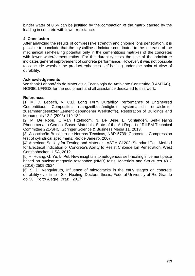
253
binder water of 0.66 can be justified by the compaction of the matrix caused by the loading in concrete with lower resistance. 4. Conclusion After analyzing the results of compressive strength and chloride ions penetration, it is possible to conclude that the crystalline admixture contributed to the increase of the mechanical self-healing potential only in the cementitious matrixes of the concretes with lower water/cement ratios. For the durability tests the use of the admixture indicates general improvement of concrete performance. However, it was not possible to conclude whether the product enhances self-healing under the point of view of durability. Acknowledgements We thank Laboratório de Materiais e Tecnologia do Ambiente Construído (LAMTAC), NORIE, UFRGS for the equipment and all assistance dedicated to this work. References [1] M. D. Lepech, V. C.Li, Long Term Durability Performance of Engineered Cementitious Composites (Langzeitbeständigkeit systematisch entwickelter zusammengesetzter Zement gebundener Werkstoffe), Restoration of Buildings and Monuments 12.2 (2006) 119-132. [2] M. De Rooij, K. Van Tittelboom, N. De Belie, E. Schlangen, Self-Healing Phenomena in Cement-Based Materials, State-of-the-Art Report of RILEM Technical Committee 221-SHC, Springer Science & Business Media 11, 2013. [3] Associação Brasileira de Normas Técnicas, NBR 5739: Concrete - Compression test of cylindrical specimens, Rio de Janeiro, 2007. [4] American Society for Testing and Materials, ASTM C1202: Standard Test Method for Electrical Indication of Concrete’s Ability to Resist Chloride Ion Penetration, West Conshohocken, USA, 2012. [5] H. Huang, G. Ye, L. Pel, New insights into autogenous self-healing in cement paste based on nuclear magnetic resonance (NMR) tests, Materials and Structures 49 7 (2016) 2509-2524. [6] S. D. Venquiaruto, Influence of microcracks in the early stages on concrete durability over time - Self-Healing, Doctoral thesis, Federal University of Rio Grande do Sul, Porto Alegre, Brazil, 2017.
Related Documents