Durability of Polymeric Glazing Materials for Solar Applications Preprint September 2003 • NREL/CP-520-34702 G. Jorgensen National Renewable Energy Laboratory S. Brunold SPF, Institut für Solartechnik Prüfung Forschung B. Carlsson and K. Möller Swedish National Testing and Research Institute M. Heck and M. Köhl Fraunhofer Institute for Solar Energy Systems To be presented at the First European Weathering Symposium Prague, Czech Republic September 25-26, 2003 National Renewable Energy Laboratory 1617 Cole Boulevard Golden, Colorado 80401-3393 NREL is a U.S. Department of Energy Laboratory Operated by Midwest Research Institute • Battelle • Bechtel Contract No. DE-AC36-99-GO10337

Welcome message from author
This document is posted to help you gain knowledge. Please leave a comment to let me know what you think about it! Share it to your friends and learn new things together.
Transcript
Durability of Polymeric Glazing Materials for Solar Applications
Preprint
September 2003 • NREL/CP-520-34702
G. Jorgensen National Renewable Energy Laboratory
S. Brunold SPF, Institut für Solartechnik Prüfung Forschung
B. Carlsson and K. Möller Swedish National Testing and Research Institute
M. Heck and M. Köhl Fraunhofer Institute for Solar Energy Systems
To be presented at the First European Weathering Symposium Prague, Czech Republic September 25-26, 2003
National Renewable Energy Laboratory 1617 Cole Boulevard Golden, Colorado 80401-3393 NREL is a U.S. Department of Energy Laboratory Operated by Midwest Research Institute • Battelle • Bechtel
Contract No. DE-AC36-99-GO10337

NOTICE
The submitted manuscript has been offered by an employee of the Midwest Research Institute (MRI), a contractor of the US Government under Contract No. DE-AC36-99GO10337. Accordingly, the US Government and MRI retain a nonexclusive royalty-free license to publish or reproduce the published form of this contribution, or allow others to do so, for US Government purposes.
This report was prepared as an account of work sponsored by an agency of the United States government. Neither the United States government nor any agency thereof, nor any of their employees, makes any warranty, express or implied, or assumes any legal liability or responsibility for the accuracy, completeness, or usefulness of any information, apparatus, product, or process disclosed, or represents that its use would not infringe privately owned rights. Reference herein to any specific commercial product, process, or service by trade name, trademark, manufacturer, or otherwise does not necessarily constitute or imply its endorsement, recommendation, or favoring by the United States government or any agency thereof. The views and opinions of authors expressed herein do not necessarily state or reflect those of the United States government or any agency thereof.
Available electronically at http://www.osti.gov/bridge
Available for a processing fee to U.S. Department of Energy and its contractors, in paper, from:
U.S. Department of Energy Office of Scientific and Technical Information P.O. Box 62 Oak Ridge, TN 37831-0062 phone: 865.576.8401 fax: 865.576.5728 email: [email protected]
Available for sale to the public, in paper, from:
U.S. Department of Commerce National Technical Information Service 5285 Port Royal Road Springfield, VA 22161 phone: 800.553.6847 fax: 703.605.6900 email: [email protected] online ordering: http://www.ntis.gov/ordering.htm
Printed on paper containing at least 50% wastepaper, including 20% postconsumer waste

1
DURABILITY OF POLYMERIC GLAZING MATERIALS FOR SOLAR APPLICATIONS
Gary Jorgensen1, Stefan Brunold2, Bo Carlsson3, Markus Heck4, Michael Köhl4,
and Kenneth Möller3
1National Renewable Energy Laboratory, Golden, CO 80401, USA
2SPF, Institut für Solartechnik Prüfung Forschung, HSR Hochschule
Rapperswil, CH-8640 Rapperswil, Switzerland 3Swedish National Testing and Research Institute, P.O. Box 857, S-501 15
Borås, Sweden 4Fraunhofer Institute for Solar Energy Systems, D-7800 Freiburg, Germany
ABSTRACT
The economic viability of solar collector systems for domestic hot water (DHW)
generation is strongly linked to the cost of such systems. Installation and
hardware costs must be reduced by 50% to allow significant market penetration
[1]. An attractive approach to cost reduction is to replace glass and metal parts
with less expensive, lighter-weight polymeric components. Weight reduction
decreases the cost of shipping, handling, and installation. The use of polymeric
materials also allows the benefits and cost savings associated with well
established manufacturing processes, along with savings associated with
improved fastening, reduced part count, and overall assembly refinements. A key
challenge is to maintain adequate system performance and assure requisite
durability for extended lifetimes. Results of preliminary and ongoing screening
tests for a large number of candidate polymeric glazing materials are presented.
Based on these results, two specific glazings are selected to demonstrate how a
service lifetime methodology can be applied to accurately predict the optical
performance of these materials during in-service use. A summary is given for
data obtained by outdoor exposure and indoor testing of polyvinyl chloride (PVC)
and polycarbonate (PC) materials, and an initial risk analysis is given for the two

2
materials. Screening tests and analyses for service lifetime prediction are
discussed. A methodology that provides a way to derive correlations between
degradation experienced by materials exposed to controlled accelerated
laboratory exposure conditions and materials exposed to in-service conditions is
given, and a validation is presented for the methodology based upon durability
test results for PVC and PC.
INTRODUCTION Polymeric glazings offer significant potential for cost savings both as direct
substitutes for glass cover plates in traditional solar collector systems and as an
integral part of all-polymeric systems. A review of polymeric solar collector
systems development efforts is provided in [2]. Cost savings result from lower
base material costs, lower manufacturing costs, and lower costs associated with
shipping, handling, and installation. Glazings must have high hemispherical
transmittance across the solar spectrum and must be able to survive at least 10
yr of exposure to service conditions including solar ultraviolet (UV) light and
operating at temperatures of 0 to 90°C. They must also retain mechanical
integrity (e.g., impact resistance and flexural rigidity) under these harsh
environmental stresses. The emphasis of current efforts is to identify new or
improved candidate glazings and to evaluate their optical and mechanical
durability during exposure to actual and simulated in-service conditions.
Recently, several reviews of candidate polymeric glazing materials have been
undertaken [3-5]. These were guided by the expectation that advances in the
polymer manufacturing and materials industry would allow identification of
potential new and improved collector glazing candidates. An international
collaborative effort surveyed commercial producers of advanced polymer
materials in the United States, Europe, and Japan [3]. The most promising class
of polymers was fluoropolymers. These have excellent thermal and optical
durability, but are expensive and are limited to use with thin-film collector
designs. Film products such as Tefzel® (ethylene-tetrafluoroethylene copolymer;
ETFE), Duralar® (also an ETFE), Halar®, Teflon®, and Kynar® exhibit very high

3
spectral transmittance, and many have sufficient tear resistance to be
considered as collector glazings [4]. Suitably UV-stabilized polyetherimide (PEI),
polyimide (PI), and polycarbonate (PC) were also suggested for consideration,
although PI is quite expensive. Preliminary exposure test data for several dozen
polymeric glazing materials being screened were reported in [4]; most materials
identified by [3] were included. These exposures have continued and further
results are discussed herein. Another complementary review also surveyed
potential polymeric glazing materials [5]. In addition to twin-walled PC,
fluoropolymer films, and multilayered polyethylene (PE) films under test,
consideration of polyurethane films, silicones, enhanced acrylics, clay-filled
thermoplastics, and polycyclohexylethylene (PeCHE) was also recommended.
Screening tests have revealed the more promising candidates, along with
glazing materials that have failed. The most common mode of failure has been
yellowing of the glazing material. These have generally included non-
fluoropolymer thin-film materials (PET and PE, including UV-stabilized
versions), and non-UV-stabilized PC constructions. Additional (less common)
modes of failure include materials developing a cloudy white opaque
appearance, temperature-related deformation and/or discoloration, and
physical damage caused by hail and other natural weathering events. Materials
that have maintained high solar-weighted hemispherical transmittance values
(>90%) after more than 2 years outdoor and accelerated exposure include:
Kynar®, Duralar®, Tefzel®, and Halar®, and PC with UV-screening layers.
Polycarbonate has high optical clarity and excellent impact strength. However,
it will yellow during UV exposure and become brittle. Recently, stabilized
versions of PC have been developed. For example, Bayer has two products
designated APEC 9351 and APEC 9353. The first is a thermally stabilized
formulation, which is offered for a maximum continuous-use temperature of up
to 180oC, and the second is stabilized for UV exposure and elevated
temperatures. General Electric has incorporated an integral UV-screening
coating into a number of its Lexan products. Because PC has excellent initial
properties and is available in a variety of forms (e.g., sheet or channeled)
suitable for use with solar collectors, it has been studied extensively as a
4
promising glazing candidate. Parallel test results for PVC serve as a control,
because it is known to weather poorly.
DURABILITY EXPOSURE TESTING
From 1993-2002, numerous samples of PVC and PC materials were exposed
to accelerated lifetime testing in laboratories and to the outdoor environment at
test sites located in Europe and in the United States by colleagues participating
in the IEA Task 10 Working Group. The details of these test results are
provided in [6]. Samples of PC and PVC, along with other candidate polymeric
glazing materials, were subjected to in-service outdoor and accelerated
laboratory exposure conditions.
Outdoor Exposure Testing
Outdoor testing was carried out in Switzerland at the Institut für Solartechnik
(SPF), in Germany at the ISE in Freiburg, and at three sites in the United
States: Golden, CO; Phoenix, AZ; and Miami, FL. A precise and detailed
knowledge of the specific environmental stress conditions experienced by
weathered samples is needed to allow understanding of site-specific
performance losses and to permit service lifetime prediction of candidate
glazings. Consequently, each operational exposure site is fully equipped with
the appropriate meteorological and radiometric instrumentation and data-
logging capability.
The materials tested are those intended for use in solar thermal flat-plate
collectors. Thus, the samples for outdoor exposure were attached to mini-
collector boxes, as illustrated in Figure 1. To simulate the elevated temperature
that collector covers are exposed to, the “mini-collectors” are made of solar
selective-coated stainless steel (solar absorptance = 0.86 ± 0.03; thermal
emittance = 0.14 ± 0.03). A thermocouple is affixed to the glazing material to
monitor sample temperature, and a reflective light shield hood is used to
prevent direct heating of the thermocouple.

5
The samples prepared in this way were exposed to the ambient climate at
locations in Europe and in the United States, facing south at an inclination
angle equal to the latitude of the site. The spectral hemispherical transmittance
of all samples was measured prior to exposure. After some time, some of the
samples were remeasured and exposed again without any cleaning. Other
samples were measured before and after cleaning and then exposed again.
Solar-weighted transmittance values integrated over the solar spectrum (τsol)
and between 400-600 nm (τ400-600) are computed as degradation indicators.
The bandwidth 400-600 nm is useful because degradation of optical
transmittance of many polymeric glazing materials is most pronounced in that
spectral range.
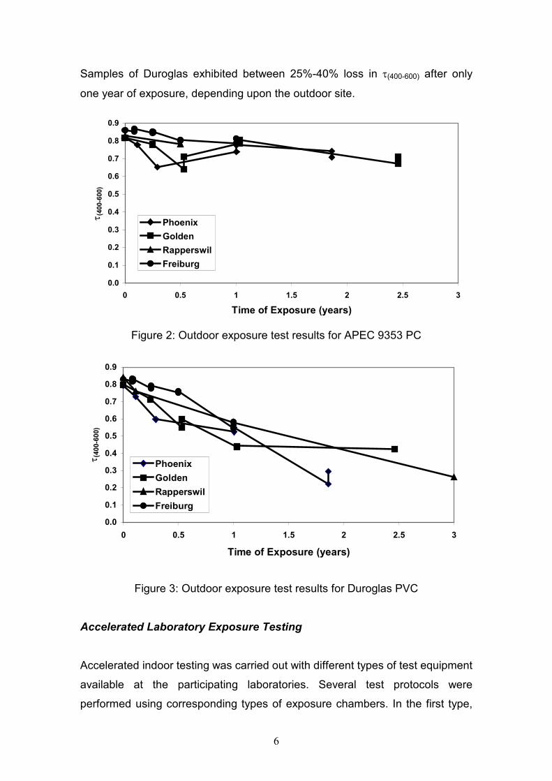
Representative τ(400-600) data are plotted in Figures 2 and 3 for APEC 9353 PC
and Duroglas PVC, respectively. The sawtooth appearance in these figures is
indicative of two measurements after the same time of exposure, with the lower
value being before cleaning and the higher value after cleaning. The data
points represent average values of typically 2-3 replicate samples. Figure 2
shows a loss in τ(400-600) of about 5% per year for samples of APEC 9353
exposed outdoors in Europe and the United States. Duroglas, a PVC glazing
material, degrades very rapidly when exposed to UV light. Figure 3 presents
outdoor test results for Duroglas exposed in the United States and Europe.
Mini-Collector Box
Glazing
Thermocouple
Reflective Light Shield Hood
140 mm Silicone Rubber Seal
Figure 1: "Mini-collectors" used for outdoor exposure of transparent cover
6
Samples of Duroglas exhibited between 25%-40% loss in τ(400-600) after only
one year of exposure, depending upon the outdoor site.
0.0
0.1
0.2
0.3
0.4
0.5
0.6
0.7
0.8
0.9
0 0.5 1 1.5 2 2.5 3
Time of Exposure (years)
τ (40
0-60
0)
PhoenixGoldenRapperswilFreiburg
Figure 2: Outdoor exposure test results for APEC 9353 PC
0.0
0.1
0.2
0.3
0.4
0.5
0.6
0.7
0.8
0.9
0 0.5 1 1.5 2 2.5 3
Time of Exposure (years)
τ (40
0-60
0)
PhoenixGoldenRapperswilFreiburg
Figure 3: Outdoor exposure test results for Duroglas PVC
Accelerated Laboratory Exposure Testing
Accelerated indoor testing was carried out with different types of test equipment
available at the participating laboratories. Several test protocols were
performed using corresponding types of exposure chambers. In the first type,

7
UV exposure was combined with various combinations of elevated temperature
and a defined level of relative humidity (RH), i.e., 60°C/80% RH, 80°C/40% RH,
and 50°C/95% RH. These tests were performed in climatic cabinets in
Rapperswil and Freiburg with an unfiltered metal halide (HMI) lamp as a light
source. The intensity of the irradiation compared to an air-mass (AM) 1.5 solar
spectrum is about three times as much UVA and seven times as much UVB.
Some irradiance occurs at wavelengths below a terrestrial AM 1.5 spectrum. In
the second type of exposure test, an Atlas Ci5000 Weather-Ometer® (WOM)
was operated at 60ºC, 60% RH, and an irradiation level of about twice an AM
1.5 solar spectrum throughout the UV and visible portion of the spectrum. In the
final test protocol, an Atlas XR35 WOM – SPART 14 test was used. The
SPART 14 test procedure was originally developed for clear coats in
automotive paint systems. This weatherability test includes acidic rain spraying.
In test method SPART 14, which is a modification of SAE J1960 [7], the Xenon
arc light source is filtered through borosilicate filters and has an irradiance level
of 0.5 W/m2 at 340 nm; this corresponds to an intensity of roughly 1.4 times an
AM 1.5 spectrum. The test cycle comprises (a) 40 min of light only; (b) 20 min
of light with water sprayed on the front surface of the sample; (c) 60 min of light
only; and (d) 60 min of no light with water sprayed on the back surface of the
sample. Every 14th cycle, the water used to spray the front of the samples is
acidic, with a pH of 3.2. The black panel temperature and relative humidity
during light periods are 70°C and 75%, respectively. The chamber temperature
and relative humidity during the dark periods are 38°C and 95%.
An exposure time of 1000 h (~6 weeks) in the SPART 14 test is estimated to
correspond to about 1.3 years of outdoor testing in Miami, Florida, for
automotive paints. Thus, 4000 h of SPART 14 testing corresponds to about 5 yr
outdoors in Florida. However, one can assume that the temperature of an
automotive coating will be at least 10ºC higher than for transparent, low light-
absorbing glazing materials. Consequently, the acceleration factor for the
glazing can be estimated to be a factor of 2 higher. Accordingly, 1000 h of
artificial weathering corresponds to 2.5 yr outdoors.

8
Highly accelerated exposure testing of selected samples using natural sunlight
was also performed at NREL [8]. Parallel testing with the relevant stress factors
of UV, temperature, RH, and acid spray at different levels was intended to allow
the sensitivity of materials degradation to these factors to be quantified, and
allow damage function models to be evaluated. These in turn can be used to
compare the time-dependent performance of these materials with measured
results from in-service outdoor exposure.
The values obtained for τ(400-600) are plotted in Figures 4 and 5 for APEC 9353,
and Duroglas, respectively, after the different types of exposure. Figure 4
shows that results for APEC 9353 exposed in the SPART 14 chamber are in
good agreement with Ci5000 data. However, exposure of APEC 9353 in the
unfiltered metal halide chambers is much more severe than in the Ci5000 and
SPART 14. With the unfiltered metal halide light source, a ~15% loss in τ(400-600)
occurs after only 25 days, whereas it took roughly 100 days for an equivalent
loss to occur in the Ci5000 and SPART 14. This may be explained by low-
wavelength (below 300 nm) irradiation associated with the metal halide light
sources.
0.0
0.1
0.2
0.3
0.4
0.5
0.6
0.7
0.8
0.9
0 50 100 150
Time of Exposure (days)
τ (40
0-60
0)
NREL 60°C / 60% RHSPF 80°C / 40% RHISE 50°C / 95% RHISE 60°C / 80% RHSPART 14
Figure 4: Accelerated exposure test results for APEC 9353 PC
9
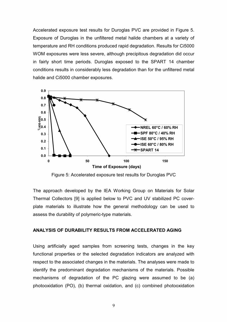
Accelerated exposure test results for Duroglas PVC are provided in Figure 5.
Exposure of Duroglas in the unfiltered metal halide chambers at a variety of
temperature and RH conditions produced rapid degradation. Results for Ci5000
WOM exposures were less severe, although precipitous degradation did occur
in fairly short time periods. Duroglas exposed to the SPART 14 chamber
conditions results in considerably less degradation than for the unfiltered metal
halide and Ci5000 chamber exposures.
0.0
0.1
0.2
0.3
0.4
0.5
0.6
0.7
0.8
0.9
0 50 100 150Time of Exposure (days)
τ (40
0-60
0)
NREL 60°C / 60% RHSPF 80°C / 40% RHISE 50°C / 95% RHISE 60°C / 80% RHSPART 14
Figure 5: Accelerated exposure test results for Duroglas PVC
The approach developed by the IEA Working Group on Materials for Solar
Thermal Collectors [9] is applied below to PVC and UV stabilized PC cover-
plate materials to illustrate how the general methodology can be used to
assess the durability of polymeric-type materials.
ANALYSIS OF DURABILITY RESULTS FROM ACCELERATED AGING
Using artificially aged samples from screening tests, changes in the key
functional properties or the selected degradation indicators are analyzed with
respect to the associated changes in the materials. The analyses were made to
identify the predominant degradation mechanisms of the materials. Possible
mechanisms of degradation of the PC glazing were assumed to be (a)
photooxidation (PO), (b) thermal oxidation, and (c) combined photooxidation

10
and hydrolysis. From the screening tests, it was concluded that only
photooxidation contributes significantly to the service life of the glazing. A
suitable time-transformation function is:
( )( )refkT/Ep
acckT/Ep
POeI
eIa
−
−
⋅
⋅= (1)
where I is the intensity of photoreactive light, T is temperature, E is an
activation energy, p is a material dependent constant, “acc” is accelerated test
conditions, and “ref” is some set of reference conditions (e.g., in-service
conditions).
For the PVC glazing, degradation mechanisms that could reduce the service
life were assumed to be (a) dehydrochlorinization, (b) photooxidation, and (c)
thermal aging. For (a), the mechanism is a chain reaction type because
hydrogen chloride formed from the dehydrogenation reaction also acts as a
catalyst for this reaction. The reaction is consequently difficult to model
mathematically in a simple way. Thus, it is difficult to express the rate of
degradation in terms of a time-transformation function. The best time-
transformation function for the PVC degradation was the same general
photooxidation time-transformation function used to model the degradation of
the PC glazing (Eq. 1).
During life-testing, PC and PVC glazing materials were exposed to the various
accelerated conditions discussed above. Hemispherical transmittance
measurements were made to characterize the loss in optical performance of
the glazing materials during these exposures. Performance-versus-time data
were thereafter used to determine the parameters of the time-transformation
function (Eq. 1). The results, obtained from a subset of the data accumulated,
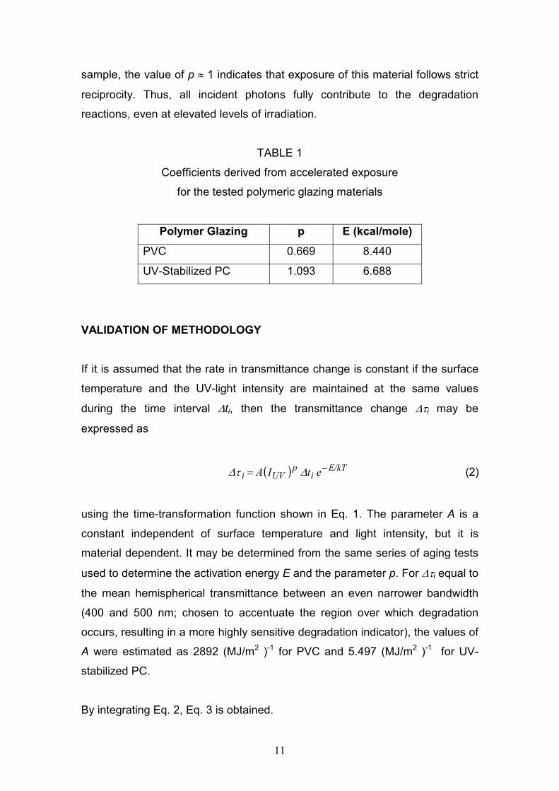
are shown in Table 1. Values of the derived activation energies, E, are
reasonable for photo-thermal degradation mechanisms. The value of p ~ 2/3 for
PVC indicates that some shielding or rate-limiting reactions occur and do not
allow all photons to participate in degradation. For the UV-stabilized PC
11
sample, the value of p ≈ 1 indicates that exposure of this material follows strict
reciprocity. Thus, all incident photons fully contribute to the degradation
reactions, even at elevated levels of irradiation.
TABLE 1
Coefficients derived from accelerated exposure
for the tested polymeric glazing materials
Polymer Glazing p E (kcal/mole)
PVC 0.669 8.440
UV-Stabilized PC 1.093 6.688
VALIDATION OF METHODOLOGY If it is assumed that the rate in transmittance change is constant if the surface
temperature and the UV-light intensity are maintained at the same values
during the time interval ∆ti, then the transmittance change ∆τi may be
expressed as
( ) E/kTi
pUVi etIA −= ∆τ∆ (2)
using the time-transformation function shown in Eq. 1. The parameter A is a
constant independent of surface temperature and light intensity, but it is
material dependent. It may be determined from the same series of aging tests
used to determine the activation energy E and the parameter p. For ∆τi equal to
the mean hemispherical transmittance between an even narrower bandwidth
(400 and 500 nm; chosen to accentuate the region over which degradation
occurs, resulting in a more highly sensitive degradation indicator), the values of
A were estimated as 2892 (MJ/m2 )-1 for PVC and 5.497 (MJ/m2 )-1 for UV-
stabilized PC.
By integrating Eq. 2, Eq. 3 is obtained.

12
( ) ( )[ ] ( )∫ −=t
0dttE/kTeptUVIAtiτ∆ (3)
Applying Eq. 3, the expected transmittance after different time periods of
outdoor exposure may be estimated.
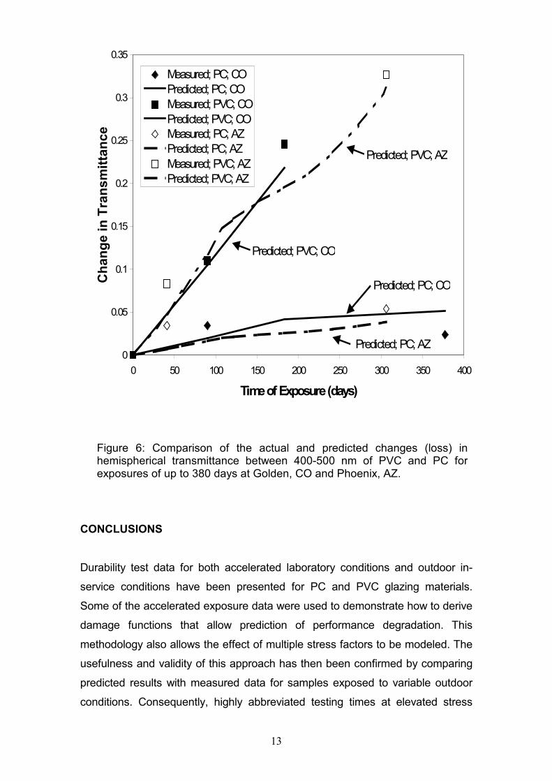
Using the values of the coefficients E and p from Table 1 and the time-
monitored values of sample temperature and UV irradiance, the loss in
performance was predicted for both the PVC and the UV-stabilized PC as
exposed outdoors in Golden, CO, and Phoenix, AZ. Predicted values were then
compared with measured data for these materials exposed at these sites. The
results are shown in Figure 6. The time-dependent changes in the weathering
variables result in the irregular shapes of the predicted curves. Excellent
agreement is evident between the measured and predicted data. Thus, the
phenomenological approach to data analysis is validated (i.e., obtaining model
coefficients from accelerated test results and then using these coefficients to
predict time-variable in-service degradation).
13
CONCLUSIONS
Durability test data for both accelerated laboratory conditions and outdoor in-
service conditions have been presented for PC and PVC glazing materials.
Some of the accelerated exposure data were used to demonstrate how to derive
damage functions that allow prediction of performance degradation. This
methodology also allows the effect of multiple stress factors to be modeled. The
usefulness and validity of this approach has then been confirmed by comparing
predicted results with measured data for samples exposed to variable outdoor
conditions. Consequently, highly abbreviated testing times at elevated stress
0
0.05
0.1
0.15
0.2
0.25
0.3
0.35
0 50 100 150 200 250 300 350 400
Time of Exposure (days)
Cha
nge
in T
rans
mitt
ance
Measured; PC; COPredicted; PC; COMeasured; PVC; COPredicted; PVC; COMeasured; PC; AZPredicted; PC; AZMeasured; PVC; AZPredicted; PVC; AZ
Predicted; PC; CO
Predicted; PC; AZ
Predicted; PVC; CO
Predicted; PVC; AZ
Figure 6: Comparison of the actual and predicted changes (loss) inhemispherical transmittance between 400-500 nm of PVC and PC for exposures of up to 380 days at Golden, CO and Phoenix, AZ.

14
conditions can be substituted for long-time exposures at lower stress levels. The
procedure developed allows much shorter development cycle times for new
materials and allows improvements to be identified and readily incorporated into
new products.
REFERENCES
1. "Solar Buildings Program Contract Summary. Calendar Year 1999,"
NREL/BK-610-28044, National Renewable Energy Laboratory, Golden, CO,
June 2000.
2. Davidson, J. H., Mantell, S. C., and Jorgensen, G. J., “Status of
Development of Polymeric Solar Water Heating Systems,” Advances in
Solar Energy, An Annual Review of Research and Development, Vol. 15, D.
Y. Goswami, Ed., American Solar Energy Society, Inc., Boulder, CO, 2003,
pp. 149-186.
3. Möller, K., “Identification of New Types of Transparent Polymeric Materials,”
IEA Task 10 Working Group on Materials in Solar Thermal Collectors
Report, November 8, 1996.
4. Raman, R. et al. “A Review of Polymer Materials for Solar Water Heating
Systems,” Journal of Solar Energy Engineering, Vol. 122, No. 2, May 2000,
pp. 92-100.
5. “Solar Hot Water Heating Systems Identification of Plastic Materials for Low
Cost Glazings,” NREL Subcontract No. TAR-9-29449-02 final report,
PolyNEW Inc., Golden, CO, 2000.
6. Jorgensen, G. J., et al. “Case Study on Polymeric Glazings,” Performance
and Durability Assessment of Optical Materials for Solar Thermal Systems,
A. W. Czanderna, Ed., Elsevier Science, in press.
7. SAE J1960, “Accelerated Exposure of Automotive Exterior Materials Using
a Controlled Irradiance Water-Cooled Xenon Arc Apparatus,” Society of
Automotive Engineers, 400 Commonwealth Drive, Warrendale, PA 15096.
8. Jorgensen G., et al. “Use of Uniformly Distributed Concentrated Sunlight for
Highly Accelerated Testing of Coatings,” Service Life Prediction
Methodology and Metrologies, ACS Symposium Series 805, J. W. Martin

15
and D. R. Bauer, Eds., American Chemical Society, Oxford University
Press, Washington, DC, 2002, 100-118.
9. Carlsson, B., et al. “Weathering of Polymer Products: Assessment of
Service Life of Solar Thermal Components by Accelerated Life Testing,”
Proceedings of the 1st European Weathering Symposium EWS (XXIIIrd
Colloquium of Danubian Countries on Natural and Artificial Ageing of
Polymers), Gesellschaft für Umweltsimulation e.V., Prague, Czech
Republic, September 25-26, 2003.
REPORT DOCUMENTATION PAGE Form Approved OMB No. 0704-0188
The public reporting burden for this collection of information is estimated to average 1 hour per response, including the time for reviewing instructions, searching existing data sources, gathering and maintaining the data needed, and completing and reviewing the collection of information. Send comments regarding this burden estimate or any other aspect of this collection of information, including suggestions for reducing the burden, to Department of Defense, Washington Headquarters Services, Directorate for Information Operations and Reports (0704-0188), 1215 Jefferson Davis Highway, Suite 1204, Arlington, VA 22202-4302. Respondents should be aware that notwithstanding any other provision of law, no person shall be subject to any penalty for failing to comply with a collection of information if it does not display a currently valid OMB control number. PLEASE DO NOT RETURN YOUR FORM TO THE ABOVE ADDRESS. 1. REPORT DATE (DD-MM-YYYY) 2. REPORT TYPE 3. DATES COVERED (From - To)
4. TITLE AND SUBTITLE 5a. CONTRACT NUMBER
5b. GRANT NUMBER
5c. PROGRAM ELEMENT NUMBER
5d. PROJECT NUMBER
5e. TASK NUMBER
5f. WORK UNIT NUMBER
6. AUTHOR(S)
7. PERFORMING ORGANIZATION NAME(S) AND ADDRESS(ES) 8. PERFORMING ORGANIZATION REPORT NUMBER
9. SPONSORING/MONITORING AGENCY NAME(S) AND ADDRESS(ES) 10. SPONSOR/MONITOR'S ACRONYM(S)
11. SPONSOR/MONITOR'S REPORT NUMBER(S)
12. DISTRIBUTION/AVAILABILITY STATEMENT
13. SUPPLEMENTARY NOTES
14. ABSTRACT
15. SUBJECT TERMS
16. SECURITY CLASSIFICATION OF: a. REPORT b. ABSTRACT c. THIS PAGE
17. LIMITATION OF ABSTRACT
18. NUMBER OF PAGES
19a. NAME OF RESPONSIBLE PERSON
19b. TELEPHONE NUMBER (Include area code)
Related Documents