DUPONT ™ ZYTEL ® HTN HIGH PERFORMANCE POLYAMIDE RESIN MOLDING GUIDE

Welcome message from author
This document is posted to help you gain knowledge. Please leave a comment to let me know what you think about it! Share it to your friends and learn new things together.
Transcript

DUPONT™ ZYTEL® HTN HIGH PERFORMANCE POLYAMIDE RESIN MOLDING GUIDE
Table of Contents
1. PROCESSING GUIDELINE SUMMARY . . . . . . . . . . . . . . . . . . . . . . . . . . . . . . . . . . . . . . . . . . . . . . . . . . . 1Drying Considerations . . . . . . . . . . . . . . . . . . . . . . . . . . . . . . . . . . . . . . . . . . . . . . . . . . . . . . . . . . . . . . . . 1Mold Temperatures . . . . . . . . . . . . . . . . . . . . . . . . . . . . . . . . . . . . . . . . . . . . . . . . . . . . . . . . . . . . . . . . . . 1Shrinkage Considerations . . . . . . . . . . . . . . . . . . . . . . . . . . . . . . . . . . . . . . . . . . . . . . . . . . . . . . . . . . . . . 1Melt Temperatures . . . . . . . . . . . . . . . . . . . . . . . . . . . . . . . . . . . . . . . . . . . . . . . . . . . . . . . . . . . . . . . . . . . 1Operating Conditions . . . . . . . . . . . . . . . . . . . . . . . . . . . . . . . . . . . . . . . . . . . . . . . . . . . . . . . . . . . . . . . . . 1
2. SAFE HANDLING INFORMATION . . . . . . . . . . . . . . . . . . . . . . . . . . . . . . . . . . . . . . . . . . . . . . . . . . . . . . . 2Safety Precautions . . . . . . . . . . . . . . . . . . . . . . . . . . . . . . . . . . . . . . . . . . . . . . . . . . . . . . . . . . . . . . . . . . . 2
3. DRYING GUIDELINES . . . . . . . . . . . . . . . . . . . . . . . . . . . . . . . . . . . . . . . . . . . . . . . . . . . . . . . . . . . . . . . . 3Effects of Moisture . . . . . . . . . . . . . . . . . . . . . . . . . . . . . . . . . . . . . . . . . . . . . . . . . . . . . . . . . . . . . . . . . . 3Moisture Absorption . . . . . . . . . . . . . . . . . . . . . . . . . . . . . . . . . . . . . . . . . . . . . . . . . . . . . . . . . . . . . . . . . 3Hopper Dryer Conditions . . . . . . . . . . . . . . . . . . . . . . . . . . . . . . . . . . . . . . . . . . . . . . . . . . . . . . . . . . . . . . 4
4. MOLDING EQUIPMENT—MOLDS . . . . . . . . . . . . . . . . . . . . . . . . . . . . . . . . . . . . . . . . . . . . . . . . . . . . . . 4Mold Temperature Control . . . . . . . . . . . . . . . . . . . . . . . . . . . . . . . . . . . . . . . . . . . . . . . . . . . . . . . . . . . . 4Mechanical Structure . . . . . . . . . . . . . . . . . . . . . . . . . . . . . . . . . . . . . . . . . . . . . . . . . . . . . . . . . . . . . . . . 5Conventional Runner System and Gate Layout . . . . . . . . . . . . . . . . . . . . . . . . . . . . . . . . . . . . . . . . . . . . 5Hot Runner Systems . . . . . . . . . . . . . . . . . . . . . . . . . . . . . . . . . . . . . . . . . . . . . . . . . . . . . . . . . . . . . . . . 8Venting . . . . . . . . . . . . . . . . . . . . . . . . . . . . . . . . . . . . . . . . . . . . . . . . . . . . . . . . . . . . . . . . . . . . . . . . . . . 9Draft Angles . . . . . . . . . . . . . . . . . . . . . . . . . . . . . . . . . . . . . . . . . . . . . . . . . . . . . . . . . . . . . . . . . . . . . . 10Sharp Corners . . . . . . . . . . . . . . . . . . . . . . . . . . . . . . . . . . . . . . . . . . . . . . . . . . . . . . . . . . . . . . . . . . . . . 10
5. MOLDING EQUIPMENT—INJECTION UNIT . . . . . . . . . . . . . . . . . . . . . . . . . . . . . . . . . . . . . . . . . . . . . 10Screw . . . . . . . . . . . . . . . . . . . . . . . . . . . . . . . . . . . . . . . . . . . . . . . . . . . . . . . . . . . . . . . . . . . . . . . . . . . 10Check Ring or Back Flow Valve . . . . . . . . . . . . . . . . . . . . . . . . . . . . . . . . . . . . . . . . . . . . . . . . . . . . . . . . 10Corrosion/Abrasion . . . . . . . . . . . . . . . . . . . . . . . . . . . . . . . . . . . . . . . . . . . . . . . . . . . . . . . . . . . . . . . . . 11Nozzles . . . . . . . . . . . . . . . . . . . . . . . . . . . . . . . . . . . . . . . . . . . . . . . . . . . . . . . . . . . . . . . . . . . . . . . . . . 11Accumulator for Thin Wall Applications . . . . . . . . . . . . . . . . . . . . . . . . . . . . . . . . . . . . . . . . . . . . . . . . . . 12
6. MOLDING PARAMETERS—START-UP AND SHUTDOWN PROCEDURES . . . . . . . . . . . . . . . . . . . . . . 12Purging . . . . . . . . . . . . . . . . . . . . . . . . . . . . . . . . . . . . . . . . . . . . . . . . . . . . . . . . . . . . . . . . . . . . . . . . . . 12Start-up . . . . . . . . . . . . . . . . . . . . . . . . . . . . . . . . . . . . . . . . . . . . . . . . . . . . . . . . . . . . . . . . . . . . . . . . . . 12Shutdown . . . . . . . . . . . . . . . . . . . . . . . . . . . . . . . . . . . . . . . . . . . . . . . . . . . . . . . . . . . . . . . . . . . . . . . . 13Interruptions . . . . . . . . . . . . . . . . . . . . . . . . . . . . . . . . . . . . . . . . . . . . . . . . . . . . . . . . . . . . . . . . . . . . . . 13
7. MOLDING PARAMETERS . . . . . . . . . . . . . . . . . . . . . . . . . . . . . . . . . . . . . . . . . . . . . . . . . . . . . . . . . . . . . 13Melt and Cylinder Temperature . . . . . . . . . . . . . . . . . . . . . . . . . . . . . . . . . . . . . . . . . . . . . . . . . . . . . . . . 13Cavity Temperature . . . . . . . . . . . . . . . . . . . . . . . . . . . . . . . . . . . . . . . . . . . . . . . . . . . . . . . . . . . . . . . . . 14Injection Phase . . . . . . . . . . . . . . . . . . . . . . . . . . . . . . . . . . . . . . . . . . . . . . . . . . . . . . . . . . . . . . . . . . . . 14Pack or Hold Pressure Phase . . . . . . . . . . . . . . . . . . . . . . . . . . . . . . . . . . . . . . . . . . . . . . . . . . . . . . . . . 14Screw Retraction Phase . . . . . . . . . . . . . . . . . . . . . . . . . . . . . . . . . . . . . . . . . . . . . . . . . . . . . . . . . . . . . 15Recommended Processing Parameters . . . . . . . . . . . . . . . . . . . . . . . . . . . . . . . . . . . . . . . . . . . . . . . . . 15
8. MATERIAL BEHAVIOR . . . . . . . . . . . . . . . . . . . . . . . . . . . . . . . . . . . . . . . . . . . . . . . . . . . . . . . . . . . . . . . 16Flow Length . . . . . . . . . . . . . . . . . . . . . . . . . . . . . . . . . . . . . . . . . . . . . . . . . . . . . . . . . . . . . . . . . . . . . . 16Shrinkage . . . . . . . . . . . . . . . . . . . . . . . . . . . . . . . . . . . . . . . . . . . . . . . . . . . . . . . . . . . . . . . . . . . . . . . . . 16Shrinkage of Zytel® HTN . . . . . . . . . . . . . . . . . . . . . . . . . . . . . . . . . . . . . . . . . . . . . . . . . . . . . . . . . . . . . 17Post-Mold Shrinkage . . . . . . . . . . . . . . . . . . . . . . . . . . . . . . . . . . . . . . . . . . . . . . . . . . . . . . . . . . . . . . . . 17
9. AUXILIARY OPERATIONS . . . . . . . . . . . . . . . . . . . . . . . . . . . . . . . . . . . . . . . . . . . . . . . . . . . . . . . . . . . . . 18Regrind . . . . . . . . . . . . . . . . . . . . . . . . . . . . . . . . . . . . . . . . . . . . . . . . . . . . . . . . . . . . . . . . . . . . . . . . . . 18Coloring . . . . . . . . . . . . . . . . . . . . . . . . . . . . . . . . . . . . . . . . . . . . . . . . . . . . . . . . . . . . . . . . . . . . . . . . . . 18
10. TROUBLESHOOTING GUIDE . . . . . . . . . . . . . . . . . . . . . . . . . . . . . . . . . . . . . . . . . . . . . . . . . . . . . . . . . 19
1
1. PROCESSING GUIDELINE SUMMARYZytel® HTN high performance polyamide resins and other DuPont thermoplastic resins may be processed on conventional injection molding machines using standard industry practices . Specific attention to processing details will enhance quality and productivity . This summary represents a key subset of the detailed molding information found in the remainder of this molding guide .
Drying ConsiderationsFor both virgin and rework, hopper dryers sized to afford the following conditions are strongly recommended:
• Moisture content must be below 0 .1 wt%
• Dry fresh bags for 6 to 8 hours at 100 °C (210 °F)
• Dryer dew point must remain below –40 °C (–40 °F)
• Air flow 3 .7 m3/kg/hr (1 cfm/lb/hr)
Note: Moisture content above 0 .1% will result in loss of strength and toughness .
Mold TemperaturesZytel® HTN crystallizes rapidly and can be successfully molded over a broad range of mold temperatures:
• HTN51 PPA 80 to 180 °C (175 to 355 °F)
• HTN52 PPA 90 to 130 °C (195 to 265 °F)
• HTN54 PPA 90 to 130 °C (195 to 265 °F)
• HTN92 PPA 90 to 110 °C (195 to 230 °F)
• HTN55 PPA 70 to 130 °C (160 to 265 °F)
• HTN53 PA 90 to 110 °C (195 to 230 °F)
• HTN59 PA 80 to 100 °C (175 to 210 °F)
Note: In order to mold Zytel® HTN into parts with optimum mechanical properties and post-molded dimensional stability, mold temperatures must be controlled to produce a sufficient level of crystallization of the polymer . Sensitivity could vary by part thickness and individual grade . Some of the ranges shown reflect reinforced, unreinforced, and flame retardant grades . See Figure 7.6 for more detail .
Shrinkage ConsiderationsShrinkage in semi-crystalline resins such as Zytel® HTN is due to:
• Crystallization of the polymer
• Thermal contraction of the part as it cools to room temperature
Causes of part distortion include:
• A high level of glass orientation
• Poor mold temperature uniformity
• Large changes in wall thickness of the part
Note: High mold temperatures and thick part sections may increase shrinkage . Shrinkage in reinforced resins is controlled by glass fiber orientation, which results in different shrink rates in parallel to and perpendicular to flow directions .
Melt TemperaturesZytel® HTN has good stability at the following general processing temperatures:
• HTN51, HTN52 PPA 320 to 330 °C (610 to 625 °F) HTN54, HTN92
• HTN55 PPA 300 to 315 °C (570 to 600 °F)
• HTN53 PA 280 to 300 °C (535 to 570 °F)
• HTN59 PA 240 to 260 °C (465 to 500 °F)
Note:
• Processing temperatures should be matched to residence (or hold-up) times (HUT)
• Excessive HUT and/or temperatures may cause degradation
• Melt temperatures below low limit can lead to unmelt
Operating Conditions• Fast injections speeds (1–3 s), especially in thin sections
• Screw speeds adjusted to result in screw retraction times shorter than the cooling phase
• Low (0 .3 MPa [50 psi]) to no back pressure; just enough to get regular dosing time and stroke
Note:
• Fast injection speed also improves general surface appearance
• High screw speeds should be avoided with glass-reinforced resins to avoid loss of mechanical properties due to glass fiber breakage
2
2. SAFE HANDLING INFORMATIONSafety PrecautionsProcessing thermoplastic resins is a generally safe operation when one complies with the following processing recommendations .
To minimize the chance of an accident, the instructions given in this text should be followed carefully . Potential hazards must be anticipated and either eliminated or guarded against by following established procedures including the use of proper protective equipment and clothing .
Be particularly alert during purging and whenever the resin is held in the machine or hot runner system at higher than usual temperatures or for longer than usual periods of time—as in a cycle interruption . Please read and insure understanding of the sections on molding parameters thoroughly .
Refer to the Safety Data Sheet for the appropriate material to become familiar with potential hazards .
A . DuPont thermoplastic resins are molded at high temperatures and contact with molten resin can inflict severe burns . At temperatures above the melting point, moisture and other gases may generate pressure which, if suddenly released, can cause the molten polymer to be violently ejected from the machine nozzle .
When purging, be sure that the high volume (booster) pump is off and that a purge shield is in place . Reduce the injection pressure and “jog” the injection forward button a few times to minimize the possibility that trapped gas in the cylinder will cause “splattering” of the resin . In the event that molten polymer does contact the skin, cool the affected area immediately with cold water or an ice pack and get medical attention for thermal burn . Do not attempt to peel the polymer from the skin .
Best practice for limiting the evolution of odors and gases is to place the purged resin immediately into a metal container of cold water .
If during molding there is any suspicion that gases are being formed in the cylinder, move the purge shield in place, back the nozzle away from the mold, turn off all heat except to the nozzle and nozzle adapter, and leave the machine until it cools below the melting point of the resin . With purge shield still in place reheat the cylinder to the minimum temperature for Zytel® HTN . If jogging the injection or screw rotation button does not produce melt flow, a plug exists . In that case, shut off cylinder heat as before and follow your established safety practices for removing the nozzle . A face shield and protective long sleeve gloves should be used .
B . For resins requiring drying prior to use, pay special attention to prevent burns as these resins are dried at high temperature . Contact with hot hoppers, ovens or air hose lines could result in severe burns . Insulation of these components will reduce this possibility . Similarly, for resins requiring hot mold temperatures, pay special attention to inadvertent contact with mold surfaces, and cooling fluid transfer lines as these may also present a burn risk .
Small amounts of gases and particulate matter (i .e ., low molecular weight modifiers) may be released during the molding, purging, drying, regrinding, and clean-up of thermoplastic resins . We recommend that adequate local exhaust ventilation be provided during the processing of DuPont thermoplastic resins . It is necessary to consider the removal of dust and particles created during the distinct processes of drying, molding, purging and regrinding all while considering the maximum residence (hold-up) times and processing temperatures .
• Thermoplastic polymers can form gaseous decomposition products during long residence times (Hold-Up Times, HUT) at the maximum recommended melt temperatures .
• Adequate local exhaust ventilation should also be provided during the regrind operation .
• Adequate local exhaust ventilation must be provided during the burnout of any equipment that contains thermoplastic resin, e .g ., nozzles, etc .
Refer to Proper Use of Local Exhaust Ventilation During Processing of Plastics for details .
C . Prior to cleaning of any barrel that may contain thermoplastic resin, the machine should be thoroughly purged with polyethylene or commercial purging compound for high melt temperature material (for HTN PPA, purge up to 350 °C (662 °F)) .
If a thermoplastic resin is accidentally purged over the heater bands, it should be removed and not allowed to degrade .
D . Pellets or granules of thermoplastic present a slipping hazard if spilled on the floor because of their size and shape . They should be swept up immediately and disposed of appropriately .
DuPont supplies Safety Data Sheet (SDS) information to its customers with the initial order of a product and on the next order after a SDS is revised . SDS’s should be referenced for information such as: significant hazards; emergency, first aid, and release measures; storage handling and exposure control and personal protection information; product information; environmental, transport and disposal considerations; and regulatory and other information .
3
3. DRYING GUIDELINES Molded parts from DuPont thermoplastic resins provide an outstanding combination of flexural modulus, strength, toughness, dimensional stability and good surface appearance . However, these properties will not be achieved in finished molded parts unless the material has been properly processed . Proper drying of the resin is an important factor . The required drying can be accomplished in conventional drying equipment, when careful attention is given to equipment selection, dryer operating conditions and maintenance procedures .
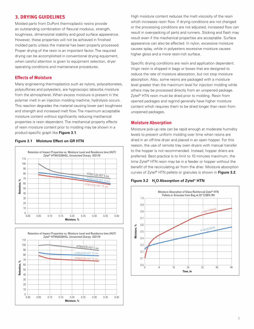
Effects of MoistureMany engineering thermoplastics such as nylons, polycarbonates, polysulfones and polyesters, are hygroscopic (absorbs moisture from the atmosphere) . When excess moisture is present in the polymer melt in an injection molding machine, hydrolysis occurs . This reaction degrades the material causing lower part toughness and strength and increased melt flow . The maximum acceptable moisture content without significantly reducing mechanical properties is resin dependent . The mechanical property effects of resin moisture content prior to molding may be shown in a product-specific graph like Figure 3.1 .
Figure 3.1 Moisture Effect on GR HTN
110
100
90
80
70
60
50
40
30
20
10
0
Rete
ntio
n, %
Moisture, %0.00 0.05 0.10 0.15 0.20 0.25 0.30 0.35 0.40
HTN51G35 HUT 5 mnHTN51G35 HUT 10 mnHTN51G35 HUT 15 mn
Retention of Impact Properties vs. Moisture Level and Residence time (HUT) Zytel® HTN51G35HSL, Unnotched Charpy ISO179
110
100
90
80
70
60
50
40
30
20
10
0
Rete
ntio
n, %
Moisture, %0.00 0.05 0.10 0.15 0.20 0.25 0.30 0.35 0.40
HTN52G35 HUT 5 mn
HTN52G35 HUT 10 mn
HTN52G35 HUT 15 mn
Retention of Impact Properties vs. Moisture Level and Residence time (HUT) Zytel® HTN52G35HSL, Unnotched Charpy ISO179
High moisture content reduces the melt viscosity of the resin which increases resin flow . If drying conditions are not changed or the processing conditions are not adjusted, increased flow can result in over-packing of parts and runners . Sticking and flash may result even if the mechanical properties are acceptable . Surface appearance can also be affected . In nylon, excessive moisture causes splay, while in polyesters excessive moisture causes higher gloss and a more resin-rich surface .
Specific drying conditions are resin and application dependent . Virgin resin is shipped in bags or boxes that are designed to reduce the rate of moisture absorption, but not stop moisture absorption . Also, some resins are packaged with a moisture level greater than the maximum level for injection molding while others may be processed directly from an unopened package . Zytel® HTN resin must be dried prior to molding . Resin from opened packages and regrind generally have higher moisture content which requires them to be dried longer than resin from unopened packages .
Moisture AbsorptionMoisture pick-up rate can be rapid enough at moderate humidity levels to prevent uniform molding over time when resins are dried in an off-line dryer and placed in an open hopper . For this reason, the use of remote tray oven dryers with manual transfer to the hopper is not recommended . Instead, hopper driers are preferred . Best practice is to limit to 10 minutes maximum, the time Zytel® HTN resin may be in a feeder or hopper without the benefit of the recirculating air from the drier . Moisture absorption curves of Zytel® HTN pellets or granules is shown in Figure 3.2 .
Figure 3.2 H2O Absorption of Zytel® HTN
Moisture Absorption of Glass Reinforced Zytel® HTNPellets or Granules from Bag at 23 °C/50% RH
HTN51G35HSL
HTN52G35HSL
1.0
0.9
0.8
0.7
0.6
0.5
0.4
0.3
0.2
0.1
0.0
Moi
stur
e, %
Time, hr0 8 16 24 32 40 48
4
Hopper Dryer ConditionsProperly operating desiccant-dehumidified-air or vacuum hopper dryers can dry thermoplastic resin adequately in a short period of time . Dehumidified or vacuum hopper dryer systems are necessary for successful drying of thermoplastic resin .
There are four critical parameters for dehumidified air systems: air flow, air temperature, air dew point and time . The ideal air flow rate is determined by each kilogram (or pound) per hour of resin processed . For each kilogram (or pound) per hour that is processed, 3 .0–3 .7 m3 per kilogram per hour (or 0 .8–1 .0 cubic foot per min, CFM, of air per pound of resin) is required . For example, if 27 kg/hr (60 lb/hr) of resin are to be molded, dry air capacity of 80–100 m3/hr (48–60 CFM) will be needed .
The air temperature is equally important and is related to the drying time . Air temperature should be measured at the point of entry to the hopper (not at the dryer) . Prolonged drying at elevated temperatures can cause the loss of some additives and discoloration of pellets or granules . When extended drying times are required, lowering the temperature is the best practice . When the temperatures required to dry resins are above 90 °C (194 °F) hoppers and air transfer lines should be well insulated to ensure drier effectiveness and to conserve energy . Dryers that incorporate an after-cooler (which lowers the temperature of return air before it enters the desiccant bed) are preferred because desiccants can remove and hold more moisture at lower temperatures . When drying at temperatures over 120 °C (250 °F), after-coolers are required .
The fourth important variable is the dew point of the air entering the hopper . This must be -30 °C (0 °F) or lower throughout the drying cycle in order to adequately dry the resin .
Vacuum dryers operate by heating the resin in a chamber to a set temperature for that resin, then indexing the chamber to a position where a vacuum is pulled to remove the moisture . The important variables are temperature, vacuum and time . The temperature depends on the resin and moisture content and the vacuum is a minimum of 6000 Pa (600 mm or 24 in of water column) . The typical times for heating and application of the vacuum are 20 minutes .
Detailed drying conditions for Zytel® HTN resins are shown in the following table .
Inlet Hopper Air Temperature 100 °C (210 °F)
Dew Point of Air –40 °C (–40 °F) or lower
Airflow Rate 3 .0 to 3 .7 m3 per kg/hr (0 .8 to 1 .0 cfm per lb/hr) resin processed
Inlet Desiccant Bed Air Temperature 65 °C (150 °F) or lower
Hopper Residence Time 6–8 hours
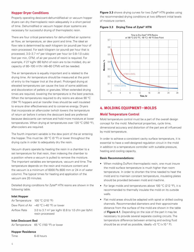
Figure 3.3 shows drying curves for two Zytel® HTN grades using the recommended drying conditions at two different initial levels of moisture content .
Figure 3.3 Drying Time of Zytel® HTN
Time to Dry Zytel® HTN Resinsat 100 °C (212 °F), –40 °C (–40 °F) Dew Point
HTN51G35HSL
HTN52G35HSL
0.7
0.6
0.5
0.4
0.3
0.2
0.1
0.0
Moi
stur
e, %
Time, hr0 8 12 16 20 244 28
4. MOLDING EQUIPMENT —MOLDS Mold Temperature Control Mold temperature control must be a part of the overall design concept for the mold . Mechanical properties, cycle time, dimensional accuracy and distortion of the part are all influenced by mold temperature .
In order to achieve a consistent cavity surface temperature, it is essential to have a well-designed regulation circuit in the mold in addition to a temperature controller with suitable pressure, heating and cooling capacity .
Basic Recommendations:
• When molding DuPont thermoplastic resin, one must insure the mold surface temperature is much higher than room temperature . In order to shorten the time needed to heat the mold and to maintain constant temperature, insulating plates should be provided between mold and machine .
• For large molds and temperatures above 100 °C (212 °F), it is recommended to thermally insulate the mold on its outside walls .
• Flat mold areas should be adapted with spiral or drilled cooling channels . Recommended diameters and their approximate distance from the surface of the mold are shown in the table of Figure 4.1 . Depending on the size of the part it may be necessary to provide several separate cooling circuits . The temperature difference between entering and exiting fluid should be as small as possible, ideally <5 °C (<10 ° F) .

5
Figure 4.1. Mold Temperature Control for Flat Parts
d
outin
dbb
ss
Wall thickness of the molding Channel diameter or width (d) Distance (s) Channel Spacing (b)
< 2 mm (0.08 in) 8 mm (0.32 in) 4 mm (0.16 in) ~ 1d
< 4 mm (0.16 in) 10 mm (0.39 in) 7 mm (0.28 in) ~ 1d
< 6 mm (0.24 in) 12 mm (0.47 in) 9 mm (0.35 in) ~ 1d
• A separate or serial cooling circuit is recommended for multi-cavity tools, because the flow rate can easily be controlled . A parallel configuration may lead to different surface temperatures as choking over time causes different flow rates in the parallel channels .
• It is important to have an efficient core cooling in order to obtain the shortest possible cycle time . Figure 4.2 shows some constructions of cooling cores .
Figure 4.2. Possible Methods of Cooling Cores
Divided tube
Internal core with spiral channelFountain
Heat conducting pin
• Separate temperature control should also be provided in slides and core-pulls when possible .
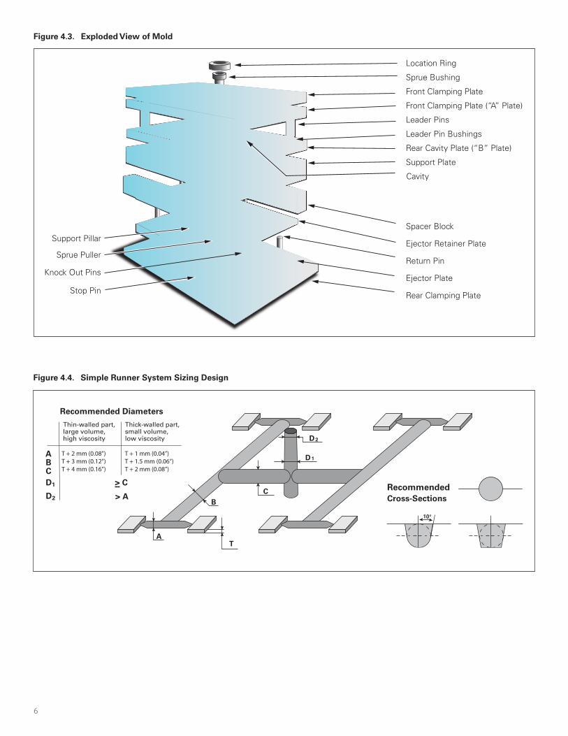
Mechanical Structure DuPont thermoplastic resin require medium to fast injection speeds . Especially in thin wall applications the specific injection pressure may exceed 100 MPa (14 .5 kpsi) . Therefore, a stiff mold construction (see Figure 4.3) will have an important contribution to:
• flash-free molding;
• longer mold lifetime;
• wider processing window (i .e ., faster injection speed) .
Recommendations for increasing mold stiffness:
• use thick platens;
• use large spacer blocks;
• use very stable frame when using many inserts or large hot runner systems;
• use support pillars between rear clamping plate and support plate .
Conventional Runner System and Gate Layout Runner (or feed) systems should efficiently convey molten polymer to the part gate in order to allow for the production of parts with a thoughtful balance between the resin pressure drop, the economics of material usage, and the resultant cycle time from runner system sizing . Ideally, the runner system should be naturally balanced and the gate type and placement on the part thoroughly considered . Runner removal, knit-line placement, resin flow length, and gate vestige allowance are all significant considerations for gate type and placement on the part . Gates are often highly stressed areas of the part and they should not be placed in mechanically critical areas . When sizing conventional feed systems, the first point to be considered is the wall thickness (T) of the molded part . The diameter of the runner should not be less than the wall thickness of the injection molded part . Starting out from the gate, the runner diameter at each branch point may be increased so that an almost constant shear rate is maintained . A simple estimate is shown in Figure 4.4 .
To prevent the inevitable cold slug from the injection nozzle reaching the molding, the sprue should always be extended so that the cold slug can be intercepted . This extension should have roughly the same diameter as the nozzle to ensure that the cold slug is retained .
6
Figure 4.4. Simple Runner System Sizing Design
Recommended Diameters
Thin-walled part, Thick-walled part,large volume,high viscosity
small volume,low viscosity
A
B
A
C
T
BC
D1
D2
D1 > C
D2 > ARecommendedCross-Sections
10°
T + 2 mm (0.08”) T + 1 mm (0.04”)T + 3 mm (0.12”) T + 1.5 mm (0.06”)T + 4 mm (0.16”) T + 2 mm (0.08”)
Figure 4.3. Exploded View of Mold
Location Ring
Sprue Bushing
Front Clamping Plate
Front Clamping Plate (“A” Plate)
Leader Pins
Leader Pin Bushings
Rear Cavity Plate (“B” Plate)
Support Plate
Cavity
Ejector Retainer Plate
Return Pin
Spacer Block
Ejector PlateKnock Out Pins
Rear Clamping Plate
Support Pillar
Stop Pin
Sprue Puller
7
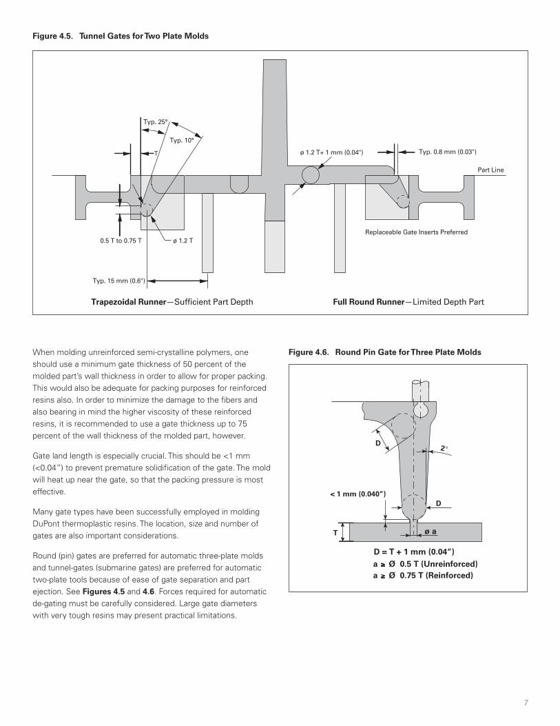
Figure 4.5. Tunnel Gates for Two Plate Molds
Full Round Runner—Limited Depth PartTrapezoidal Runner—Suf�cient Part Depth
Part Line
Replaceable Gate Inserts Preferred0.5 T to 0.75 T
Typ. 10°
ø 1.2 T
Typ. 25°
T
Typ. 15 mm (0.6")
Typ. 0.8 mm (0.03")ø 1.2 T+ 1 mm (0.04")
When molding unreinforced semi-crystalline polymers, one should use a minimum gate thickness of 50 percent of the molded part’s wall thickness in order to allow for proper packing . This would also be adequate for packing purposes for reinforced resins also . In order to minimize the damage to the fibers and also bearing in mind the higher viscosity of these reinforced resins, it is recommended to use a gate thickness up to 75 percent of the wall thickness of the molded part, however .
Gate land length is especially crucial . This should be <1 mm (<0 .04”) to prevent premature solidification of the gate . The mold will heat up near the gate, so that the packing pressure is most effective .
Many gate types have been successfully employed in molding DuPont thermoplastic resins . The location, size and number of gates are also important considerations .
Round (pin) gates are preferred for automatic three-plate molds and tunnel-gates (submarine gates) are preferred for automatic two-plate tools because of ease of gate separation and part ejection . See Figures 4.5 and 4.6 . Forces required for automatic de-gating must be carefully considered . Large gate diameters with very tough resins may present practical limitations .
Figure 4.6. Round Pin Gate for Three Plate Molds
2°
D
D
< 1 mm (0.040”)
ø a
a ≥ Ø 0.5 T (Unreinforced)a ≥ Ø 0.75 T (Reinforced)
T
D = T + 1 mm (0.04”)
8
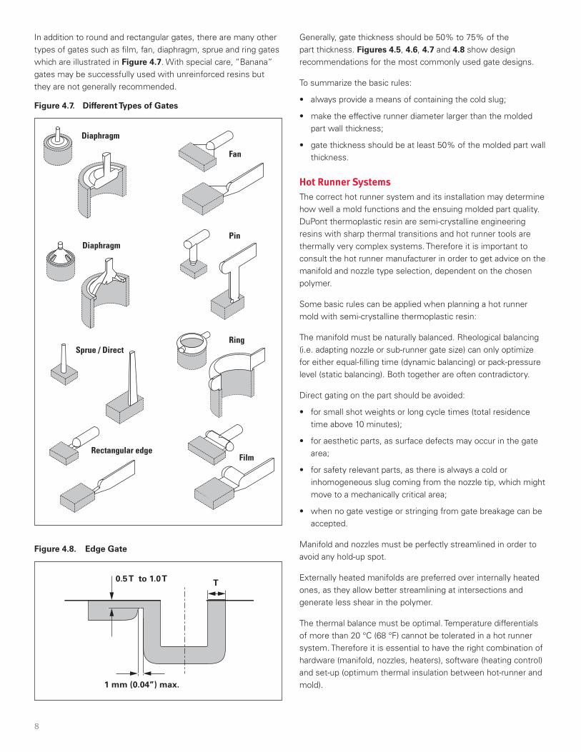
In addition to round and rectangular gates, there are many other types of gates such as film, fan, diaphragm, sprue and ring gates which are illustrated in Figure 4.7 . With special care, “Banana” gates may be successfully used with unreinforced resins but they are not generally recommended .
Figure 4.7. Different Types of Gates
Diaphragm
Diaphragm
Sprue / Direct
Rectangular edgeFilm
Fan
Pin
Ring
Figure 4.8. Edge Gate
0.5 T to 1.0 T T
1 mm (0.04”) max.
Generally, gate thickness should be 50% to 75% of the part thickness . Figures 4.5, 4.6, 4.7 and 4.8 show design recommendations for the most commonly used gate designs .
To summarize the basic rules:
• always provide a means of containing the cold slug;
• make the effective runner diameter larger than the molded part wall thickness;
• gate thickness should be at least 50% of the molded part wall thickness .
Hot Runner Systems The correct hot runner system and its installation may determine how well a mold functions and the ensuing molded part quality . DuPont thermoplastic resin are semi-crystalline engineering resins with sharp thermal transitions and hot runner tools are thermally very complex systems . Therefore it is important to consult the hot runner manufacturer in order to get advice on the manifold and nozzle type selection, dependent on the chosen polymer .
Some basic rules can be applied when planning a hot runner mold with semi-crystalline thermoplastic resin:
The manifold must be naturally balanced . Rheological balancing (i .e . adapting nozzle or sub-runner gate size) can only optimize for either equal-filling time (dynamic balancing) or pack-pressure level (static balancing) . Both together are often contradictory .
Direct gating on the part should be avoided:
• for small shot weights or long cycle times (total residence time above 10 minutes);
• for aesthetic parts, as surface defects may occur in the gate area;
• for safety relevant parts, as there is always a cold or inhomogeneous slug coming from the nozzle tip, which might move to a mechanically critical area;
• when no gate vestige or stringing from gate breakage can be accepted .
Manifold and nozzles must be perfectly streamlined in order to avoid any hold-up spot .
Externally heated manifolds are preferred over internally heated ones, as they allow better streamlining at intersections and generate less shear in the polymer .
The thermal balance must be optimal . Temperature differentials of more than 20 °C (68 °F) cannot be tolerated in a hot runner system . Therefore it is essential to have the right combination of hardware (manifold, nozzles, heaters), software (heating control) and set-up (optimum thermal insulation between hot-runner and mold) .

9
“Self-insulating” nozzles should be avoided . This kind of nozzle requires the polymer to flow into a cup-shaped gap between nozzle tip and mold surface, in order to optimize the thermal insulation of the nozzle tip . With semi-crystalline polymers, however, the resin in this gap may partially solidify and ultimately thermally degrade . This can create black spots and surface defects at irregular intervals .
“Free Flow” nozzle types are preferred to those with torpedo tips, unless there are specific requirements for the resulting gate vestige .
Specific abrasion resistant metals or treatments are preferred for reinforced grades, specifically at the nozzle tip, where shear is highest . Hard metal tips have led to much longer life-times of the tip . Nozzle tips should also be exchangeable . This allows for easier control of the effects of abrasion, and may reduce the cost of modifications, if they are necessary .
When heating up a hot runner containing DuPont thermoplastic resin, it is important to first heat the system to approximately 20 °C (35 °F) below the melting point of the resin and then to wait at least 30 minutes at this temperature before heating up to operational temperature . This allows heat to soak in and attainment of a heat balance . Modern controllers allow for such an automated stepwise start-up procedure .
Figure 4.9. Parting Line Venting
Mold Cavity
Mold Edge
Relief channel depth (D)
Vent depth (d)
Vent width (W)
Vent land (L)
Vent width (W) = As wide as feasible, but typically >3mm (0.12")
Vent area for gas escape = W x d
Relief channel depth (D) >0.8 mm (0.03") opened to ~3 mm (0.12") after 25 mm (1.0") from mold cavity
Vent land (L) = 0.8 to 1.0 mm (0.03" to 0.04") max.
MaterialVent Depth (d), mm (in)
Min. Max.Crastin® PBT
0 .012 (0 .0005)0 .02 (0 .0008)
Rynite® PETSorona® PTT
Zytel® and Minlon® PA resinsZytel® HTN resins
Delrin® POM 0 .03 (0 .0012)Hytrel® TPC-ET 0 .04 (0 .0015)
When there is a doubt about hold-up spots in the hot runner, it is advisable to make a color change on the cylinder and then mold continuously for an additional 10 minutes . The system can be shut down and the hot runner and nozzle then disassembled in order to identify the spots which still contain the first color . With the help of the hot runner manufacturer it should be possible to improve the streamlining of the hot runner and nozzle .
Venting Inadequate mold venting can cause the following problems:
• Poor weld line strength;
• Discoloration (burning);
• Erosion or corrosion of the mold;
• Dimensional variation on the molded part;
• Surface aesthetic defects like bubbles or blisters:
• Short shots .
Both cavities and runners should be vented at the parting line and the ejectors as recommended in Figures 4.9, 4.10 and 4.11 .
Figure 4.10. Cavity and Runner Venting
Vent land
End of �ow
Vent channel
Figure 4.11. Ejector Venting
d
10
The area of the vent must be large enough (W * d) to prevent a rise in gas pressure within the mold cavity . The vent land length (L) should not exceed 1 mm . The area of the escape passage leading from the vent should increase in proportion to its distance from the cavity edge . In the case of low viscosity grades and where there must be a minimum of flash, venting may be conservatively sized (made more shallow) and increased as required .
Draft Angles Mold surfaces that are perpendicular to the parting line should be tapered to allow easy part ejection . These include ribs, bosses and sides . A taper (draft angle) of 0 .5° to 1° per side is usually satisfactory with DuPont thermoplastic resins . Softer, more elastic resins may require slightly higher taper to 2° per side .
Sharp Corners Part designs and mold finish requirements should adhere to the basic rules of rounding sharp internal corners of a part . Radius will make parts and runner less brittle when demolding . Parts from unreinforced resins are far more sensitive to the notch effect of sharp corners as shown in Figure 4.12 .
Figure 4.12 Effect of Sharp Corners and Glass Reinforcement
100
90
80
70
60
50
40
30
20
10
0
Not
ched
Impa
ct, k
J/m
2
30% Glass Reinforced Zytel®
Unreinforced Zyte
l®
Radius, mm
Impact Performance vs. Notch RadiusISO 179
0 0.1 0.2 0.3 0.4 0.5 0.6 0.7 0.8 0.9 1.0 1.1
94
37
19
8
20
24
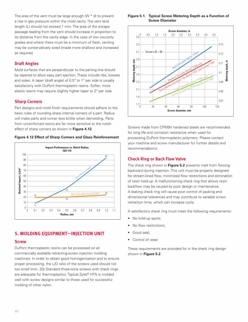
5. MOLDING EQUIPMENT—INJECTION UNIT Screw DuPont thermoplastic resins can be processed on all commercially available retracting-screw injection molding machines . In order to obtain good homogenization and to ensure proper processing, the L/D ratio of the screws used should not too small (min . 20) .Standard three-zone screws with check rings are adequate for thermoplastics . Typical Zytel® HTN is molded well with screw designs similar to those used for successful molding of other nylon .
Figure 5.1. Typical Screw Metering Depth as a Function of Screw Diameter
3.5
3.3
3.1
2.9
2.7
2.5
2.3
2.1
1.9
1.7
0.13
0.12
0.11
0.1
0.09
0.08
0.07
Met
erin
g de
pth,
mm
Met
erin
g de
pth,
in
Screw diameter, mm
Screw diameter, in
0 20 40 60 80 100 120
0.50
Screw L/D = 20
1.0 1.5 2.0 2.5 3.0 3.5 4.0 4.5
High Viscosity Delrin® POM
Medium Viscosity Delrin® POM and
Glass Reinforced Zytel® PA, Rynite® PET, and Crastin
® PBT
Low Viscosity Delrin® POM and
Unreinforced Zytel® PA and Crastin® PBT
High Viscosity Delrin® POM
Medium Viscosity Delrin® POM and
Glass Reinforced Zytel® PA, Rynite® PET, and Crastin
® PBT
Low Viscosity Delrin® POM and
Unreinforced Zytel® PA and Crastin® PBT
Screws made from CPM9V hardened steels are recommended for long life and corrosion resistance when used for processing DuPont thermoplastic polymers . Please contact your machine and screw manufacturer for further details and recommendations .
Check Ring or Back Flow Valve The check ring shown in Figure 5.2 prevents melt from flowing backward during injection . This unit must be properly designed for stream-lined flow, minimized flow restrictions and elimination of resin hold-up . A malfunctioning check ring that allows resin backflow may be caused by poor design or maintenance . A leaking check ring will cause poor control of packing and dimensional tolerances and may contribute to variable screw retraction time, which can increase cycle .
A satisfactory check ring must meet the following requirements:
• No hold-up spots;
• No flow restrictions;
• Good seal;
• Control of wear .
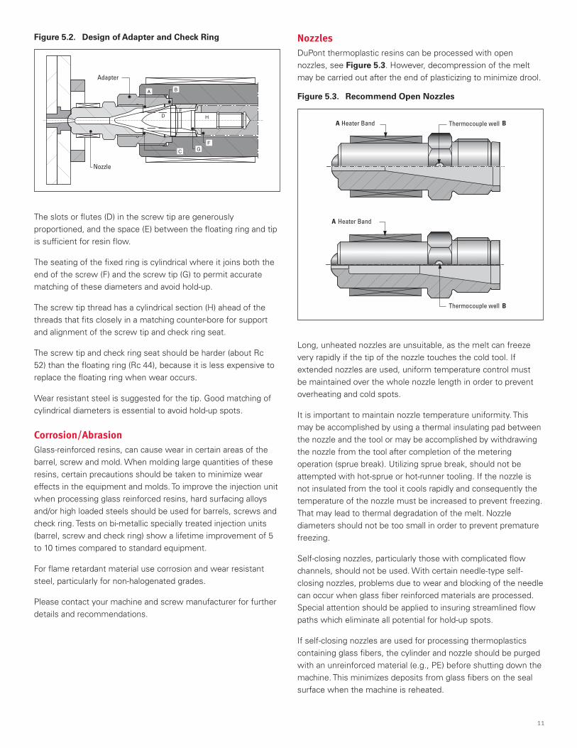
These requirements are provided for in the check ring design shown in Figure 5.2 .
11
Figure 5.2. Design of Adapter and Check Ring
Nozzle
Adapter
A
D HE
B
GF
C
The slots or flutes (D) in the screw tip are generously proportioned, and the space (E) between the floating ring and tip is sufficient for resin flow .
The seating of the fixed ring is cylindrical where it joins both the end of the screw (F) and the screw tip (G) to permit accurate matching of these diameters and avoid hold-up .
The screw tip thread has a cylindrical section (H) ahead of the threads that fits closely in a matching counter-bore for support and alignment of the screw tip and check ring seat .
The screw tip and check ring seat should be harder (about Rc 52) than the floating ring (Rc 44), because it is less expensive to replace the floating ring when wear occurs .
Wear resistant steel is suggested for the tip . Good matching of cylindrical diameters is essential to avoid hold-up spots .
Corrosion/Abrasion Glass-reinforced resins, can cause wear in certain areas of the barrel, screw and mold . When molding large quantities of these resins, certain precautions should be taken to minimize wear effects in the equipment and molds . To improve the injection unit when processing glass reinforced resins, hard surfacing alloys and/or high loaded steels should be used for barrels, screws and check ring . Tests on bi-metallic specially treated injection units (barrel, screw and check ring) show a lifetime improvement of 5 to 10 times compared to standard equipment .
For flame retardant material use corrosion and wear resistant steel, particularly for non-halogenated grades .
Please contact your machine and screw manufacturer for further details and recommendations .
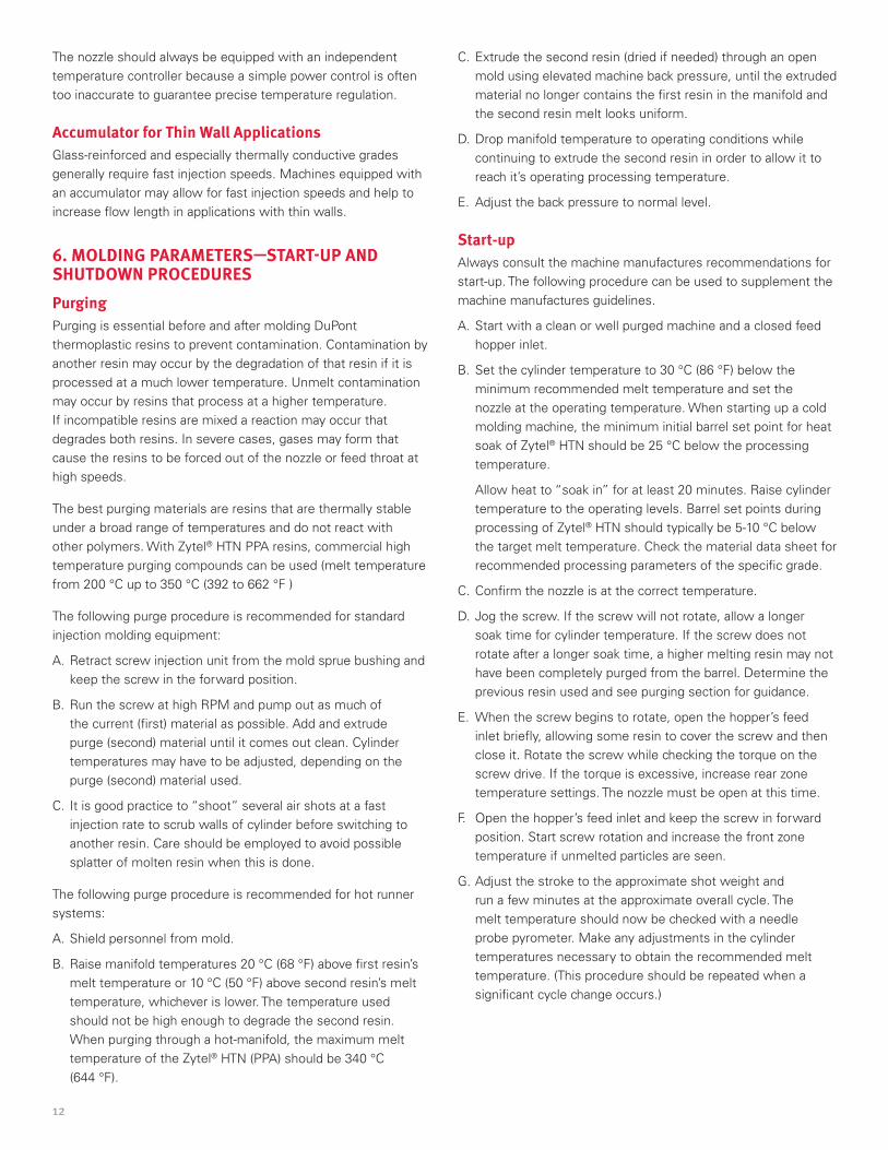
Nozzles DuPont thermoplastic resins can be processed with open nozzles, see Figure 5.3 . However, decompression of the melt may be carried out after the end of plasticizing to minimize drool .
Figure 5.3. Recommend Open Nozzles
Thermocouple wellHeater BandA B
Heater Band
Thermocouple well
A
B
Long, unheated nozzles are unsuitable, as the melt can freeze very rapidly if the tip of the nozzle touches the cold tool . If extended nozzles are used, uniform temperature control must be maintained over the whole nozzle length in order to prevent overheating and cold spots .
It is important to maintain nozzle temperature uniformity . This may be accomplished by using a thermal insulating pad between the nozzle and the tool or may be accomplished by withdrawing the nozzle from the tool after completion of the metering operation (sprue break) . Utilizing sprue break, should not be attempted with hot-sprue or hot-runner tooling . If the nozzle is not insulated from the tool it cools rapidly and consequently the temperature of the nozzle must be increased to prevent freezing . That may lead to thermal degradation of the melt . Nozzle diameters should not be too small in order to prevent premature freezing .
Self-closing nozzles, particularly those with complicated flow channels, should not be used . With certain needle-type self-closing nozzles, problems due to wear and blocking of the needle can occur when glass fiber reinforced materials are processed . Special attention should be applied to insuring streamlined flow paths which eliminate all potential for hold-up spots .
If self-closing nozzles are used for processing thermoplastics containing glass fibers, the cylinder and nozzle should be purged with an unreinforced material (e .g ., PE) before shutting down the machine . This minimizes deposits from glass fibers on the seal surface when the machine is reheated .
12
The nozzle should always be equipped with an independent temperature controller because a simple power control is often too inaccurate to guarantee precise temperature regulation .
Accumulator for Thin Wall Applications Glass-reinforced and especially thermally conductive grades generally require fast injection speeds . Machines equipped with an accumulator may allow for fast injection speeds and help to increase flow length in applications with thin walls .
6. MOLDING PARAMETERS—START-UP AND SHUTDOWN PROCEDURESPurging Purging is essential before and after molding DuPont thermoplastic resins to prevent contamination . Contamination by another resin may occur by the degradation of that resin if it is processed at a much lower temperature . Unmelt contamination may occur by resins that process at a higher temperature . If incompatible resins are mixed a reaction may occur that degrades both resins . In severe cases, gases may form that cause the resins to be forced out of the nozzle or feed throat at high speeds .
The best purging materials are resins that are thermally stable under a broad range of temperatures and do not react with other polymers . With Zytel® HTN PPA resins, commercial high temperature purging compounds can be used (melt temperature from 200 °C up to 350 °C (392 to 662 °F )
The following purge procedure is recommended for standard injection molding equipment:
A . Retract screw injection unit from the mold sprue bushing and keep the screw in the forward position .
B . Run the screw at high RPM and pump out as much of the current (first) material as possible . Add and extrude purge (second) material until it comes out clean . Cylinder temperatures may have to be adjusted, depending on the purge (second) material used .
C . It is good practice to “shoot” several air shots at a fast injection rate to scrub walls of cylinder before switching to another resin . Care should be employed to avoid possible splatter of molten resin when this is done .
The following purge procedure is recommended for hot runner systems:
A . Shield personnel from mold .
B . Raise manifold temperatures 20 °C (68 °F) above first resin’s melt temperature or 10 °C (50 °F) above second resin’s melt temperature, whichever is lower . The temperature used should not be high enough to degrade the second resin . When purging through a hot-manifold, the maximum melt temperature of the Zytel® HTN (PPA) should be 340 °C (644 °F) .
C . Extrude the second resin (dried if needed) through an open mold using elevated machine back pressure, until the extruded material no longer contains the first resin in the manifold and the second resin melt looks uniform .
D . Drop manifold temperature to operating conditions while continuing to extrude the second resin in order to allow it to reach it’s operating processing temperature .
E . Adjust the back pressure to normal level .
Start-upAlways consult the machine manufactures recommendations for start-up . The following procedure can be used to supplement the machine manufactures guidelines .
A . Start with a clean or well purged machine and a closed feed hopper inlet .
B . Set the cylinder temperature to 30 °C (86 °F) below the minimum recommended melt temperature and set the nozzle at the operating temperature . When starting up a cold molding machine, the minimum initial barrel set point for heat soak of Zytel® HTN should be 25 °C below the processing temperature .
Allow heat to “soak in” for at least 20 minutes . Raise cylinder temperature to the operating levels . Barrel set points during processing of Zytel® HTN should typically be 5-10 °C below the target melt temperature . Check the material data sheet for recommended processing parameters of the specific grade .
C . Confirm the nozzle is at the correct temperature .
D . Jog the screw . If the screw will not rotate, allow a longer soak time for cylinder temperature . If the screw does not rotate after a longer soak time, a higher melting resin may not have been completely purged from the barrel . Determine the previous resin used and see purging section for guidance .
E . When the screw begins to rotate, open the hopper’s feed inlet briefly, allowing some resin to cover the screw and then close it . Rotate the screw while checking the torque on the screw drive . If the torque is excessive, increase rear zone temperature settings . The nozzle must be open at this time .
F . Open the hopper’s feed inlet and keep the screw in forward position . Start screw rotation and increase the front zone temperature if unmelted particles are seen .
G . Adjust the stroke to the approximate shot weight and run a few minutes at the approximate overall cycle . The melt temperature should now be checked with a needle probe pyrometer . Make any adjustments in the cylinder temperatures necessary to obtain the recommended melt temperature . (This procedure should be repeated when a significant cycle change occurs .)
13
H . Bring injection cylinder forward . Start with a transfer position that will create a short shot and no pack pressure (except where short shots will interfere with safe part ejection) . Establish the proper transfer position for the injection rate and then adjust the molding variables for the best part appearance and maximum part weight .
ShutdownThe machine should be purged thoroughly (see “Purging”) which cuts the time required for subsequent start-up and reduces risk of contamination . The following shutdown procedure is suggested:
A . Shut the hopper’s feed inlet while continuing to mold on cycle .
B . Empty the barrel and add a sufficient quantity of the appropriate purge resin such as high temperature purge compounds and extrude until the purge is clean .
Run the screw until the screw pumps itself dry .
C . Leave screw in forward position .
D . Shut down power supply .
InterruptionsMolding cycle interruptions may cause the resin in the barrel of the molding machine or the hot manifold to degrade . The maximum time allowed before degradation occurs depends on the resin being molded and whether the processing temperature is at the upper or lower limit for that resin . Consult the processing guides for the resin being molded for specific recommendations .
If short molding interruptions occur which exceed 2 minutes, it is essential that the cylinder is purged with fresh resin . Failure to purge after interruptions to the molding cycle may lead to defective parts being produced due to thermal degradation of the material . The actual number of unacceptable parts will depend upon the percentage of the melted volume used for each shot .
If the molding interruption duration exceeds 15 minutes, it is recommended to empty the cylinder and to lower the cylinder temperature to 30 °C processing temperature for Zytel® HTN in order to avoid excessive thermal degradation .
Additional care should be taken when molding Zytel® HTN through a hot manifold . When the shot weight is a small portion of the resin in the hot manifold, the hot manifold must also be purged with fresh resin after a long cycle interruption .
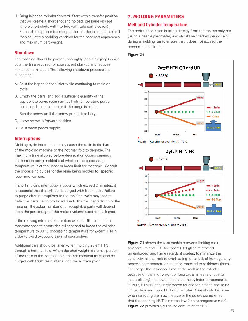
7. MOLDING PARAMETERS Melt and Cylinder TemperatureThe melt temperature is taken directly from the molten polymer (using a needle pyrometer) and should be checked periodically during a molding run to ensure that it does not exceed the recommended limits .
Figure 7.1
Figure 7.1 shows the relationship between limiting melt temperature and HUT for Zytel® HTN glass reinforced, unreinforced, and flame retardant grades . To minimize the sensitivity of the melt to overheating, or to lack of homogeneity, processing temperatures must be matched to residence times . The longer the residence time of the melt in the cylinder, because of low shot weight or long cycle times (e .g . due to insert placing), the lower should be the cylinder temperatures . HTN92, HTNFR, and unreinforced toughened grades should be limited to a maximum HUT of 6 minutes . Care should be taken when selecting the machine size or the screw diameter so that the resulting HUT is not too low (non homogenous melt) . Figure 7.2 provides a guideline calculation for HUT .
14
Figure 7.2
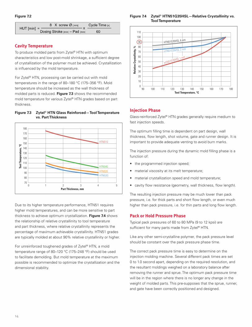
Cavity TemperatureTo produce molded parts from Zytel® HTN with optimum characteristics and low post-mold shrinkage, a sufficient degree of crystallization of the polymer must be achieved . Crystallization is influenced by the mold temperature .
For Zytel® HTN, processing can be carried out with mold temperatures in the range of 80–180 °C (175–356 °F) . Mold temperature should be increased as the wall thickness of molded parts is reduced . Figure 7.3 shows the recommended mold temperature for various Zytel® HTN grades based on part thickness .
Figure 7.3 Zytel® HTN Glass Reinforced—Tool Temperature vs. Part Thickness
180
170
160
150
140
130
120
110
100
90
80
70
Tool
Tem
pera
ture
, °C
Part Thickness, mm0 1 2 3 4 5
HTN52G
HTN54G
HTN53G
HTN51G
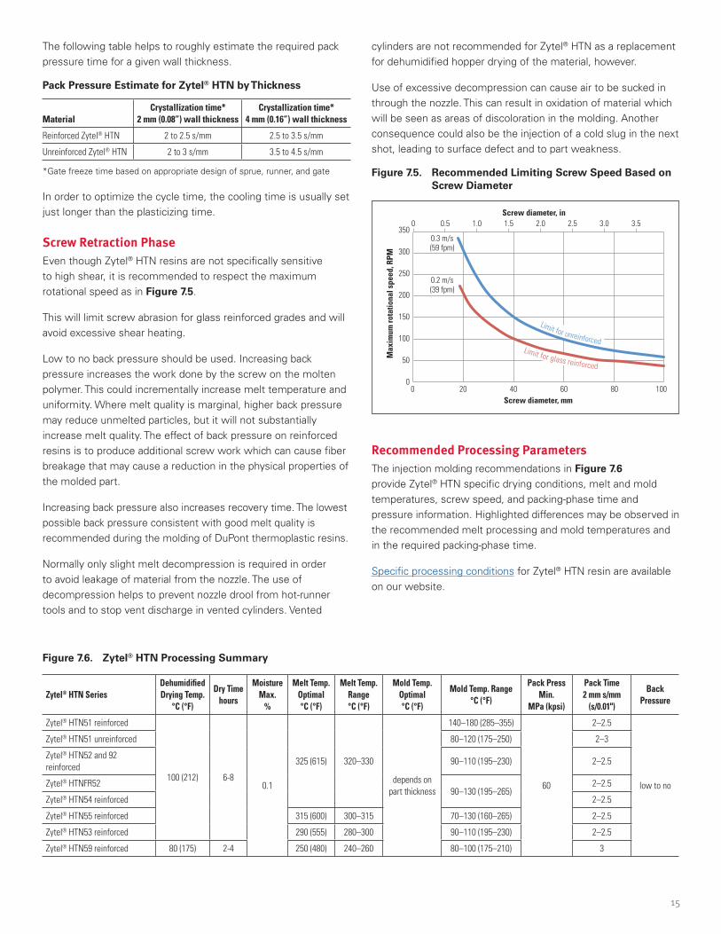
Due to its higher temperature performance, HTN51 requires higher mold temperatures, and can be more sensitive to part thickness to achieve optimum crystallization . Figure 7.4 shows the relationship of relative crystallinity to tool temperature and part thickness, where relative crystallinity represents the percentage of maximum achievable crystallinity . HTN51 grades are typically molded at about 90% relative crystallinity or higher .
For unreinforced toughened grades of Zytel® HTN, a mold temperature range of 80–120 °C (175–248 °F) should be used to facilitate demolding . But mold temperature at the maximum possible is recommended to optimize the crystallization and the dimensional stability .
Figure 7.4 Zytel® HTN51G35HSL—Relative Crystallinity vs. Tool Temperature
110
100
90
80
70
60
50
40
30
20
10
0
Rela
tive
Crys
talli
nity
, %
Tool Temperature, °C90 100 110 120 130 140 150 160 180170
HTN51G35HSL 4 mm
HTN51G35HSL 2 mm
HTN51G35HSL 1 mm
Injection PhaseGlass-reinforced Zytel® HTN grades generally require medium to fast injection speeds .
The optimum filling time is dependent on part design, wall thickness, flow length, shot volume, gate and runner design . It is important to provide adequate venting to avoid burn marks .
The injection pressure during the dynamic mold filling phase is a function of:
• the programmed injection speed;
• material viscosity at its melt temperature;
• material crystallization speed and mold temperature;
• cavity flow resistance (geometry, wall thickness, flow length) .
The resulting injection pressure may be much lower than pack pressure, i .e . for thick parts and short flow length, or even much higher than pack pressure, i .e . for thin parts and long flow length .
Pack or Hold Pressure Phase Typical pack pressures of 60 to 80 MPa (9 to 12 kpsi) are sufficient for many parts made from Zytel® HTN .
Like any other semi-crystalline polymer, the pack pressure level should be constant over the pack pressure phase time .
The correct pack pressure time is easy to determine on the injection molding machine . Several different pack times are set 0 to 1 .0 second apart, depending on the required resolution, and the resultant moldings weighed on a laboratory balance after removing the runner and sprue . The optimum pack pressure time will be in the region where there is no longer any change in the weight of molded parts . This pre-supposes that the sprue, runner, and gate have been correctly positioned and designed .
15
The following table helps to roughly estimate the required pack pressure time for a given wall thickness .
Pack Pressure Estimate for Zytel® HTN by Thickness
MaterialCrystallization time*
2 mm (0.08”) wall thickness Crystallization time*
4 mm (0.16”) wall thickness
Reinforced Zytel® HTN 2 to 2.5 s/mm 2.5 to 3.5 s/mm
Unreinforced Zytel® HTN 2 to 3 s/mm 3.5 to 4.5 s/mm
*Gate freeze time based on appropriate design of sprue, runner, and gate
In order to optimize the cycle time, the cooling time is usually set just longer than the plasticizing time .
Screw Retraction PhaseEven though Zytel® HTN resins are not specifically sensitive to high shear, it is recommended to respect the maximum rotational speed as in Figure 7.5 .
This will limit screw abrasion for glass reinforced grades and will avoid excessive shear heating .
Low to no back pressure should be used . Increasing back pressure increases the work done by the screw on the molten polymer . This could incrementally increase melt temperature and uniformity . Where melt quality is marginal, higher back pressure may reduce unmelted particles, but it will not substantially increase melt quality . The effect of back pressure on reinforced resins is to produce additional screw work which can cause fiber breakage that may cause a reduction in the physical properties of the molded part .
Increasing back pressure also increases recovery time . The lowest possible back pressure consistent with good melt quality is recommended during the molding of DuPont thermoplastic resins .
Normally only slight melt decompression is required in order to avoid leakage of material from the nozzle . The use of decompression helps to prevent nozzle drool from hot-runner tools and to stop vent discharge in vented cylinders . Vented
cylinders are not recommended for Zytel® HTN as a replacement for dehumidified hopper drying of the material, however .
Use of excessive decompression can cause air to be sucked in through the nozzle . This can result in oxidation of material which will be seen as areas of discoloration in the molding . Another consequence could also be the injection of a cold slug in the next shot, leading to surface defect and to part weakness .
Figure 7.5. Recommended Limiting Screw Speed Based on Screw Diameter
350
300
250
200
150
100
50
0M
axim
um ro
tatio
nal s
peed
, RPM
Screw diameter, mm
Screw diameter, in
0 20 40 60 80 100
0.50
0.3 m/s(59 fpm)
0.2 m/s(39 fpm)
1.0 1.5 2.0 2.5 3.0 3.5
Limit for glass reinforced
Limit for unreinforced
Recommended Processing ParametersThe injection molding recommendations in Figure 7.6 provide Zytel® HTN specific drying conditions, melt and mold temperatures, screw speed, and packing-phase time and pressure information . Highlighted differences may be observed in the recommended melt processing and mold temperatures and in the required packing-phase time .
Specific processing conditions for Zytel® HTN resin are available on our website .
Figure 7.6. Zytel® HTN Processing Summary
Zytel® HTN SeriesDehumidified Drying Temp.
°C (°F)
Dry Time hours
Moisture Max.
%
Melt Temp. Optimal °C (°F)
Melt Temp. Range °C (°F)
Mold Temp. Optimal °C (°F)
Mold Temp. Range °C (°F)
Pack Press Min.
MPa (kpsi)
Pack Time 2 mm s/mm
(s/0.01")
Back Pressure
Zytel® HTN51 reinforced
100 (212) 6-80.1
325 (615) 320–330
depends on part thickness
140–180 (285–355)
60
2–2.5
low to no
Zytel® HTN51 unreinforced 80–120 (175–250) 2–3
Zytel® HTN52 and 92 reinforced
90–110 (195–230) 2–2.5
Zytel® HTNFR52 90–130 (195–265)
2–2.5
Zytel® HTN54 reinforced 2–2.5
Zytel® HTN55 reinforced 315 (600) 300–315 70–130 (160–265) 2–2.5
Zytel® HTN53 reinforced 290 (555) 280–300 90–110 (195–230) 2–2.5
Zytel® HTN59 reinforced 80 (175) 2-4 250 (480) 240–260 80–100 (175–210) 3

16
8. MATERIAL BEHAVIORFlow LengthZytel® HTN high performance polyamide resin has good flow properties . Flow length data are generated on molds with a “spiral” or “snake” flow pattern . Data from one study can vary compared to some from other studies, as flow length is highly dependent on:
• molding parameters (fill speed, melt temperature, moisture, residence time and pack pressure and time );
• mold layout (channel width, gate design) and mold temperature;
• type of molding machine (valve response time, ability to avoid hydraulic pressure peaks at v/p switch point) .
Figure 8.1 and 8.2 show the flow properties with snake flow of common glass reinforced Zytel® HTN grades, respectively . The indicated flow lengths, at wall typical molding thicknesses of 1 to 2 .5 mm (0 .04 to 0 .1 in), were determined for this specific snake flow geometry when run without pack pressure .
Figure 8.1 Flow Length at 1 mm (0.040") Thickness
40 60 80 100 120
Injection Pressure, MPa
Flow
, mm
180
160
140
120
100
80
60
40
20
HTNFR52G30BL
HTN52G35HSLHTN51G35HSL
HTN54G50HSLHTN51G45HSL
HTN53G50HSLR
Zytel® HTN Flow Length1 mm thickness, injection speed 35 mm/sec
Figure 8.2 Flow Length at 3.2 mm (0.126") Thickness
40 60 80 100 120
Injection Pressure, MPa
Flow
, mm
800
700
600
500
400
300
200
100
0
HTNFR52G30BL
HTN52G35HSLHTN51G35HSLHTN51G45HSL
HTN54G50HSLHTN53G50HSLR
Zytel® HTN Flow Length3.2 mm thickness, injection speed 35 mm/sec
ShrinkageFor amorphous thermoplastics, shrinkage is caused primarily by contraction of the molded part as it cools to room temperature .
In semi-crystalline thermoplastics, which includes Zytel® HTN resins, shrinkage is also influenced considerably by the crystallization of the polymer . The degree of crystallization depends largely on the transient and local temperature changes in the molding . High mold temperatures and heavy wall thickness (high heat content of the melt) promote crystallization and therefore increase shrinkage .
Optimum runner and gate design, as well as adequate pack pressure time are necessary in order to achieve minimum shrinkage with semi-crystalline polymers .
Figure 8.3 Shrinkage of Zytel® HTN
1.0
0.9
0.8
0.7
0.6
0.5
0.4
0.3
0.2
0.1
0.0
Shri
nkag
e, %
HTN51G35HSL HTN52G35HSL HTN54G35HSL HTN55G55TLW HTN53G50LRHF HTN59G55LWSF
Zytel® HTN ShrinkageISO 294, Plate 60 x 60 x 2 mm, Hold Pressure 90 MPa
ParallelNormal
0.65
0.95
0.20
0.30
0.70
0.60
0.20 0.20 0.20
0.10 0.10
0.25
17
Shrinkage of Zytel® HTNFor glass-fiber-reinforced Zytel® HTN, shrinkage is considerably influenced by the direction in which the glass fibers are oriented . As a result, there is a larger difference in shrinkage parallel and normal to the direction of flow and this makes accurate prediction of the shrinkage difficult . Depending on the fiber orientation, which is determined by the way in which the mold fills, resulting shrinkage values may lie between the longitudinal and transverse shrinkage values shown in Figure 8.3 . In extreme cases, the difference in shrinkage may be greater than that shown .
The degree to which the glass fibers orient themselves is determined by the design of the part, the design and position of the gate, and details of flow conditions . This orientation is best predicted with specialized computational analysis .
The amount of glass fibers also have an effect on the shrinkage behavior of the Zytel® HTN resin . As shown in Figure 8.4 the shrinkage in the flow direction will be higher for a smaller percentage of glass fiber reinforcement . This also shows that the shrinkage differential between flow direction and transverse flow direction is lower for the lower glass loading .
Figure 8.4 Shrinkage vs. Level of Glass Reinforcement
0.9
0.8
0.7
0.6
0.5
0.4
0.3
0.2
0.1
0.0
Shri
nkag
e, %
Hold Pressure, MPa40 50 60 70 80 90 100 110 120
Normal 15% GF
Parallel 15% GF
Normal 45% GF
Parallel 45% GF
Normal 35% GF
Parallel 35% GF
Zytel® HTN51G35 Shrinkage vs. Glass Fibers and Hold PressureISO 294, Plate 60 x 60 x 2 mm
Shrinkage data for specific Zytel® HTN resins at 2 mm thickness according to ISO 294-4 is available on our website .
Post-Mold ShrinkagePost-mold shrinkage may be defined as the dimensional change (in %) of a molded part measured at 23 ± 2 °C (73 ± 3 .5 °F) after annealing for a specific period at a specific temperature .
Complex parts may require lower annealing temperatures and time, in order to minimize deformation at annealing temperatures . We recommend some trials in order to find optimum annealing conditions when annealing is necessary .
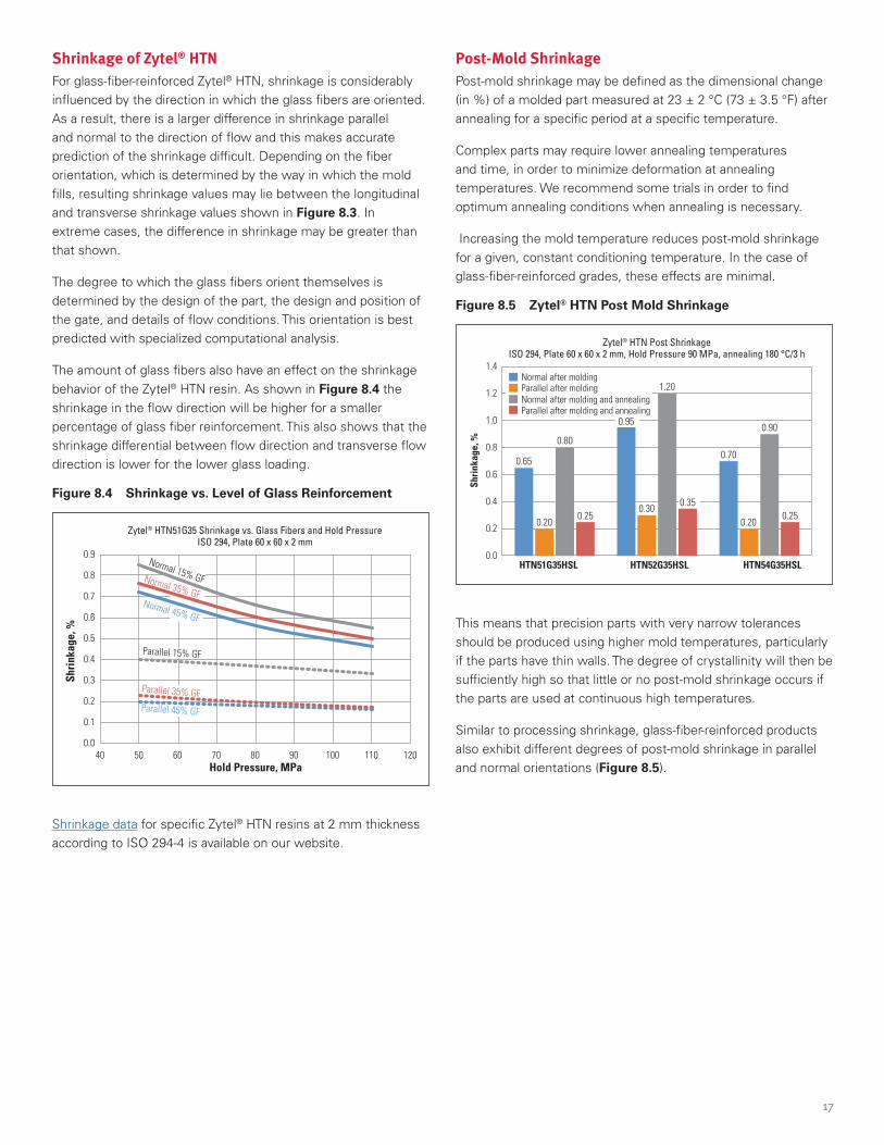
Increasing the mold temperature reduces post-mold shrinkage for a given, constant conditioning temperature . In the case of glass-fiber-reinforced grades, these effects are minimal .
Figure 8.5 Zytel® HTN Post Mold Shrinkage
1.4
1.2
1.0
0.8
0.6
0.4
0.2
0.0
Shri
nkag
e, %
HTN51G35HSL HTN52G35HSL HTN54G35HSL
Zytel® HTN Post ShrinkageISO 294, Plate 60 x 60 x 2 mm, Hold Pressure 90 MPa, annealing 180 °C/3 h
Parallel after moldingNormal after molding and annealingParallel after molding and annealing
Normal after molding
0.65
0.20
0.80
0.95
0.250.30
1.20
0.35
0.70
0.20
0.90
0.25
This means that precision parts with very narrow tolerances should be produced using higher mold temperatures, particularly if the parts have thin walls . The degree of crystallinity will then be sufficiently high so that little or no post-mold shrinkage occurs if the parts are used at continuous high temperatures .
Similar to processing shrinkage, glass-fiber-reinforced products also exhibit different degrees of post-mold shrinkage in parallel and normal orientations (Figure 8.5) .

18
9. AUXILIARY OPERATIONSRegrindOnly regrind from optimally processed original material should be used .
The actual amount of regrind which can be added must be determined for each part by testing . Only the operational and performance requirements of a molded part can determine the amount of regrind that can be acceptable .
In order to keep the loss of strength and toughness at a low level, no more than 25% regrind by weight should be added to reinforced products, and no more than 40% for unreinforced products . In the case of glass-fiber-reinforced grades, increased loss of strength must be expected due to the reduction of fiber length which occurs during regrinding . The retention of tensile strength of Zytel® HTN with 25 and 50 % regrind percentages and repeated use is shown in Figure 9.1 .
Figure 9.1 Retention of Tensile Strength vs. Pass Number for Zytel® HTN Resins*
50% Regrind
25% Regrind
1 2 3 4 5 6
100
98
96
94
92
90
Pass Number
Tens
ile S
tren
gth,
% R
eten
tion
*Based on maintaining all feed moisture less than 0 .1%
Recycled material should have approximately the same size as fresh pellets or fresh granules . Grinder screens with a mesh size of about 5 mm (0 .2”) yield a grain size of approximately 3 mm (0 .12”) in diameter . A screen with a mesh of approximately 2 .5 mm (0 .1”) can be used for removing dust particles in the regrind . Before processing, the regrind should be dried to avoid the possibility of degradation due to the presence of moisture .
ColoringA range of colorants can be added to DuPont thermoplastic resins . The freedom of design is even greater in that almost any coloring system can be used: dry pigment, paste, liquid color or dyes . Such systems can also lead to variations in properties and/or performance .
When using colorants, special attention should be given to:
• Chemical compatibility with base resin .
• Good thermal stability above the processing temperature of the resin .
• Using only approved color formulations when working within regulated industries .
• Shrinkage variation due to the colorants, which can affect the crystallization rate . Additionally, the carrier of liquid colors can be considered as a surface lubricant, which may cause screw slippage leading to screw feeding and/or filling problems .
To obtain optimum, homogeneous dispersion of colorant:
• Use a ratio between polymer and master-batch that can be acceptably mixed with available injection molding equipment .
• Ideally, use a screw with a mixing head, or use a high-compression screw .
• Use a screw retraction stroke less than 30% of the maximum screw retraction of the machine .

19
10. TROUBLESHOOTING GUIDEThe following troubleshooting guide is meant to provide prioritized suggestions for the improvement of issues seen in plastic parts and their processing . Please identify the column of the issue of concern and read down to each row of the suggested remedies in numerical order . It is often more practical to explore the sensitivity of a processing parameter like pack time first, before exploring a more time consuming and costly change in gate size, for example .
Figure 10.1. Zytel® HTN Processing Troubleshooting Guide
Suggested Remedies Brittle Parts
Short Shots
Voids in Parts Sinks Burned
PartsWarped
PartsWeak
Knit linesSticking
SprueSticking
PartsPoor Part Surface Flashing Drool Mold
Deposit
Ensure Resin is dry 1 1 1 1
Change Injection Pressure 2 2 2 2 5 2 2 3 4
Increase Injection Speed 3 4 2 6
Decrease Injection Speed 4 3 3 5 3
More Screw Forward Time 3 3 7
Less Screw Forward Time 8 3
Check Melt Temperature 2 4 5 5 1 6 6 4 3 3 1
Increase Mold Temperature 5 3 1 1
Check Nozzle Temperature 1 2
Increase Gate (feed system) Size 7 6 6 5 9 7
Increase Venting Capacity 6 7 2 3 8 4
Use Reverse Taper Nozzle 4 4
Decrease Residence Time 3 7 5 2
Change Cycle 4 4 4 7
Check Pad Size (Cushion) 1 1 1
Repair Mold 5 5 6
Increase Taper 6 6
Change Gate Location 8 7 6 5 7 10 7
Reduce Regrind Level 4
Balance Mold Temperature 1 6
Check Puller Design 7
Check for Contamination 5 8 2 5
Check for Voids 6
Check V-P Change Point 9 4 2
Add Melt Decompression 7
Check Clamp Force 5
Check Hot Runner System 7 8 11 6 8

20
NOTES

NOTES

The information provided in this data sheet corresponds to DuPont knowledge on the subject at the date of its publication. This information may be subject to revision as new knowledge and experience becomes available. The data provided fall within the normal range of product properties and relate only to the specific material designated; these data may not be valid for such material used in combination with any other materials, additives or pigments or in any process, unless expressly indicated otherwise.
The data provided should not be used to establish specification limits or used alone as the basis of design; they are not intended to substitute for any testing you may need to conduct to determine for yourself the suitability of a specific material for your particular purposes. Since DuPont cannot anticipate all variations in actual end-use and disposal conditions, DuPont does not guarantee results, makes no warranties and assumes no liability in connection with any use of this information. All such information is given and accepted at the buyer’s risk. It is intended for use by persons having technical skill, at their own discretion and risk. Nothing in this publication is to be considered as a license to operate under or a recommendation to infringe any patent.
CAUTION: Do not use DuPont materials in medical applications involving implantation in the human body or contact with internal body fluids or tissues unless the material has been provided from DuPont under a written contract that is consistent with DuPont policy regarding medical applications and expressly acknowledges the contemplated use. For further information, please contact your DuPont representative. You may also request a copy of DuPont POLICY Regarding Medical Applications H-50103-5 and DuPont CAUTION Regarding Medical Applications H-50102-5.
Copyright © DuPont. The DuPont Oval Logo, DuPont™ and Zytel® are trademarks or registered trademarks of E.I. du Pont de Nemours and Company or its affiliates. All rights reserved.
(04/16) ZYE-A11187-00-B0815
Visit us at plastics.dupont.com or zytelhtn.dupont.com
Contact DuPont at the following regional locations:
North America +1-302-999-4592
Greater China +86-400-8851-888
Latin America +0800 17 17 15
Japan +81-3-5521-8600
Europe, Middle East, Africa +41 22 717 51 11
ASEAN +65 6586 3688
Cover photo courtesy of Winzeler Inc . Photographed by Erich Schrempp Photography and Digital Imaging Studio
Related Documents