Dunlop Air Bellows . . . 2018

Welcome message from author
This document is posted to help you gain knowledge. Please leave a comment to let me know what you think about it! Share it to your friends and learn new things together.
Transcript
Dunlop Air Bellows . . .
2018
www.dunlopsystems.com 2 PNEURIDE
2
CONTENTS Introduction ............................................................................... 3 Data Summary: Aluminium-plated Bellow Assemblies ................ 5 Data Summary: Steel-plated Bellow Assemblies ......................... 6 Bellow Assembly Data Sheets ..................................................... 9 Section 1: Aluminium Alloy Clamping Plates ............................ 10 2¾ x 2 ........................................................................................................... 11 2¾ x 3 ........................................................................................................... 13 4½ x 1 ........................................................................................................... 15 4½ x 2 ........................................................................................................... 17 4½ x 3 ........................................................................................................... 19 6 x 1 .............................................................................................................. 21 6 x 2 .............................................................................................................. 23 6 x 3 .............................................................................................................. 25 Section 2: Steel Clamping Plates .............................................. 27 6 x 1 .............................................................................................................. 28 6 x 2 .............................................................................................................. 30 6 x 3 .............................................................................................................. 32 8 x 1 .............................................................................................................. 34 8 x 2 .............................................................................................................. 36 8 x 3 .............................................................................................................. 38 9¼ x 2 ........................................................................................................... 40 10 x 1 ............................................................................................................ 42 10 x 2 ............................................................................................................ 44 10 x 3 ............................................................................................................ 46 12 x 1 ............................................................................................................ 48 12 x 2 ............................................................................................................ 50 12 x 2E .......................................................................................................... 52 12 x 3 ............................................................................................................ 54 14½ x 1 ......................................................................................................... 56 14½ x 2 (4-stud Mounting Plates) ..................................................................... 58 14½ x 2 (8-Stud Mounting Plates) ..................................................................... 60 14½ x 3 ......................................................................................................... 62 16 x 2 ............................................................................................................ 64 16 x 3 ............................................................................................................ 66 Section 3: Large Bellow ........................................................... 68 21½ x 2 ......................................................................................................... 69
www.dunlopsystems.com 3 PNEURIDE
3
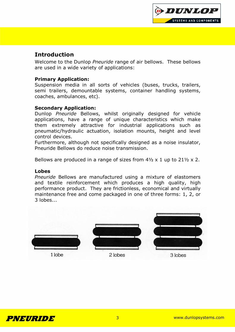
Introduction Welcome to the Dunlop Pneuride range of air bellows. These bellows are used in a wide variety of applications: Primary Application: Suspension media in all sorts of vehicles (buses, trucks, trailers, semi trailers, demountable systems, container handling systems, coaches, ambulances, etc). Secondary Application: Dunlop Pneuride Bellows, whilst originally designed for vehicle applications, have a range of unique characteristics which make them extremely attractive for industrial applications such as pneumatic/hydraulic actuation, isolation mounts, height and level control devices. Furthermore, although not specifically designed as a noise insulator, Pneuride Bellows do reduce noise transmission. Bellows are produced in a range of sizes from 4½ x 1 up to 21½ x 2. Lobes Pneuride Bellows are manufactured using a mixture of elastomers and textile reinforcement which produces a high quality, high performance product. They are frictionless, economical and virtually maintenance free and come packaged in one of three forms: 1, 2, or 3 lobes...
www.dunlopsystems.com 4 PNEURIDE
4
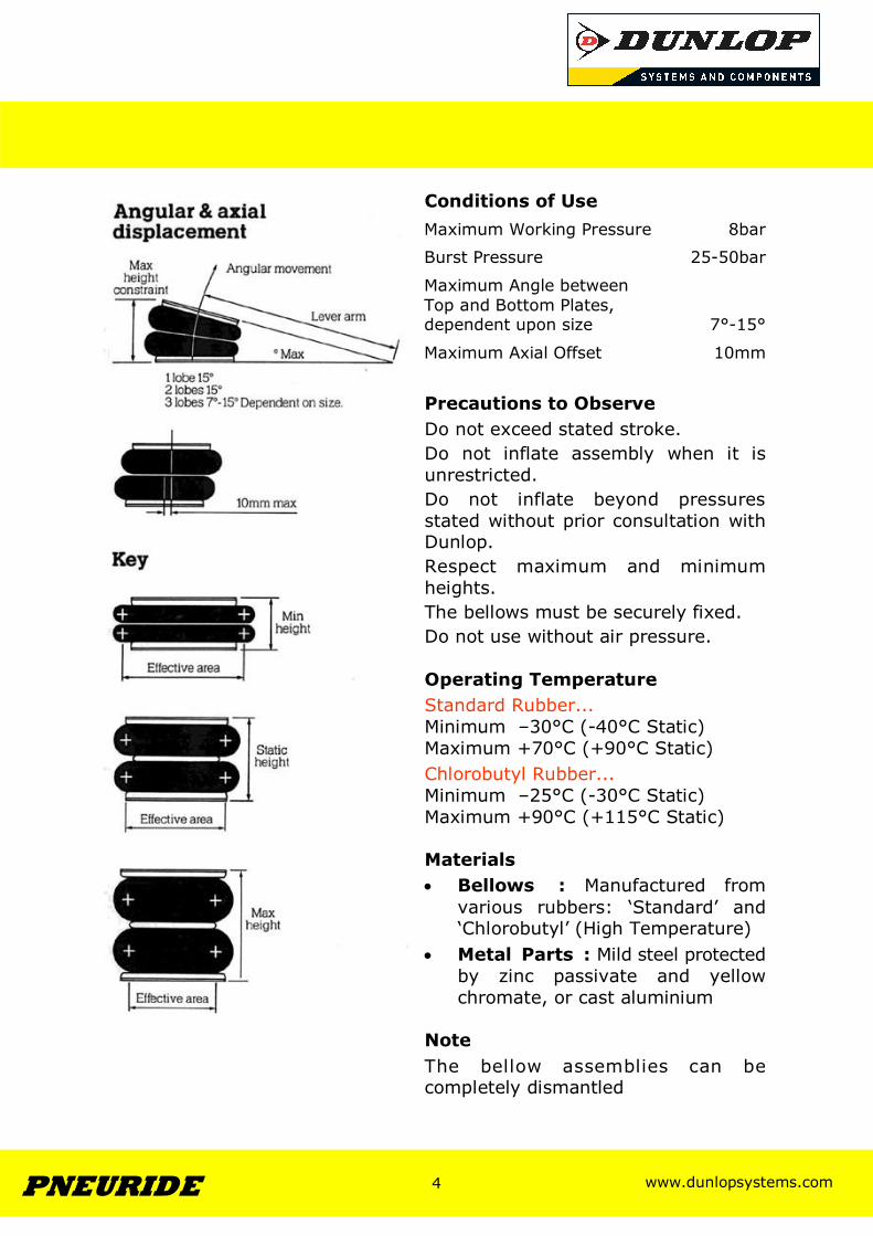
Conditions of Use
Precautions to Observe Do not exceed stated stroke. Do not inflate assembly when it is unrestricted. Do not inflate beyond pressures stated without prior consultation with Dunlop. Respect maximum and minimum heights. The bellows must be securely fixed. Do not use without air pressure. Operating Temperature Standard Rubber... Minimum –30°C (-40°C Static) Maximum +70°C (+90°C Static) Chlorobutyl Rubber... Minimum –25°C (-30°C Static) Maximum +90°C (+115°C Static) Materials • Bellows : Manufactured from
various rubbers: ‘Standard’ and ‘Chlorobutyl’ (High Temperature)
• Metal Parts : Mild steel protected by zinc passivate and yellow chromate, or cast aluminium
Note The bellow assemblies can be completely dismantled
Maximum Working Pressure 8bar
Burst Pressure 25-50bar
Maximum Angle between Top and Bottom Plates, dependent upon size
7°-15°
Maximum Axial Offset 10mm
www.dunlopsystems.com 5 PNEURIDE
5
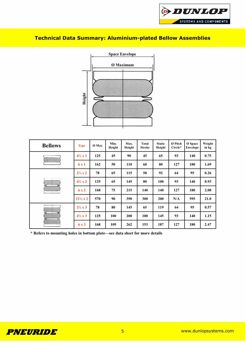
Bellows Type Ø Max Min. Height
Max. Height
Total Stroke
Static Height
Ø Pitch Circle*
Ø Space Envelope
Weight in kg
4½ x 1 125 45 90 45 65 93 140 0.75
6 x 1 162 50 110 60 80 127 180 1.69
2¾ x 2 78 65 115 50 92 64 95 0.26
4½ x 2 125 65 145 80 100 93 140 0.93
6 x 2 168 75 215 140 140 127 180 2.08
2¾ x 3 78 80 145 65 119 64 95 0.57
4½ x 3 125 100 200 100 145 93 140 1.15
6 x 3 168 109 262 153 187 127 180 2.47
21½ x 2 570 90 390 300 200 N/A 595 21.0
Hei
ght
Ø Maximum
Space Envelope
Technical Data Summary: Aluminium-plated Bellow Assemblies
* Refers to mounting holes in bottom plate—see data sheet for more details
www.dunlopsystems.com 6 PNEURIDE
6
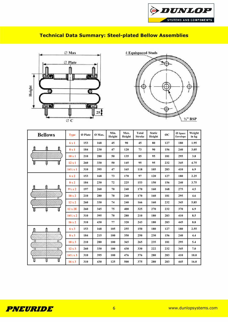
Bellows Type Ø Plate Ø Max. Min. Height
Max. Height
Total Stroke
Static Height ØC Ø Space
Envelope Weight in kg
6 x 1 153 168 45 90 45 80 127 180 1.95
8 x 1 184 230 47 120 73 90 156 240 3.05
10 x 1 210 280 50 135 85 95 181 295 3.8
12 x 1 260 330 50 145 95 95 232 345 4.75
14½ x 1 310 395 47 165 118 105 283 410 6.9
6 x 2 153 168 73 170 97 120 127 180 2.25
8 x 2 184 230 72 225 153 150 156 240 3.75
9¼ x 2 197 260 70 240 170 160 168 275 4.5
10 x 2 210 280 70 240 170 160 181 295 4.6
12 x 2 260 330 74 240 166 160 232 345 5.85
12 x 2E 260 345 75 400 325 270 232 370 6.9
14½ x 2 310 395 70 280 210 180 283 410 8.5
16 x 2 310 430 77 320 243 180 283 445 8.8
6 x 3 153 168 105 255 150 180 127 180 2.55
8 x 3 184 215 100 350 250 230 156 240 4.4
10 x 3 210 280 100 365 265 235 181 295 5.4
12 x 3 260 330 100 430 330 222 232 345 7.0
14½ x 3 310 395 100 476 376 280 283 410 10.0
16 x 3 310 430 125 500 375 280 283 445 16.0
Technical Data Summary: Steel-plated Bellow Assemblies
∅ Max
∅ Plate
Hei
ght
4 Equispaced Studs
½” BSP
25
∅ C
www.dunlopsystems.com 7 PNEURIDE
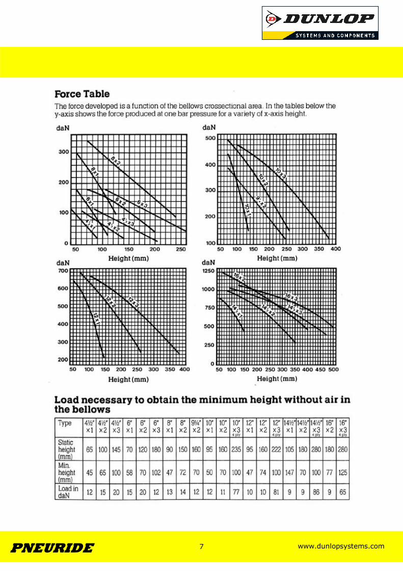
7
www.dunlopsystems.com 8 PNEURIDE
8
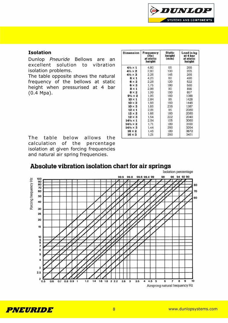
Isolation Dunlop Pneuride Bellows are an excellent solution to vibration isolation problems. The table opposite shows the natural frequency of the bellows at static height when pressurised at 4 bar (0.4 Mpa). The table below al lows the calculation of the percentage isolation at given forcing frequencies and natural air spring frequencies.

www.dunlopsystems.com 9 PNEURIDE
9
Technical Data
General Dimensions
Bellows Schematic
Bellows Mounting Data
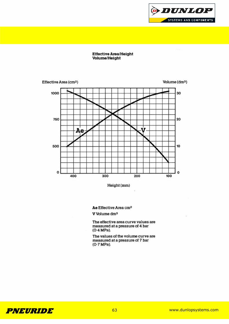
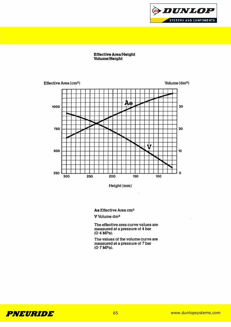
Effective Area Curves
Volume Curves
Bellow Assembly Data Sheets
www.dunlopsystems.com 10 PNEURIDE
10
Section 1
Bellows with Aluminium Alloy Clamping Plates
www.dunlopsystems.com 11 PNEURIDE
11
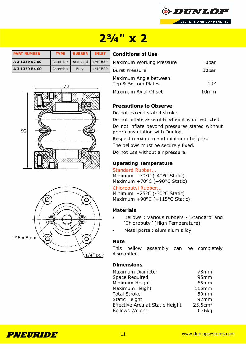
2¾" x 2 Conditions of Use
Precautions to Observe Do not exceed stated stroke. Do not inflate assembly when it is unrestricted. Do not inflate beyond pressures stated without prior consultation with Dunlop. Respect maximum and minimum heights. The bellows must be securely fixed. Do not use without air pressure. Operating Temperature Standard Rubber... Minimum –30°C (-40°C Static) Maximum +70°C (+90°C Static) Chlorobutyl Rubber... Minimum –25°C (-30°C Static) Maximum +90°C (+115°C Static) Materials • Bellows : Various rubbers - ‘Standard’ and
‘Chlorobutyl’ (High Temperature) • Metal parts : aluminium alloy Note This bellow assembly can be completely dismantled Dimensions Maximum Diameter 78mm Space Required 95mm Minimum Height 65mm Maximum Height 115mm Total Stroke 50mm Static Height 92mm Effective Area at Static Height 25.5cm2
Bellows Weight 0.26kg
Maximum Working Pressure 10bar
Burst Pressure 30bar
Maximum Angle between Top & Bottom Plates
10°
Maximum Axial Offset 10mm
92
78
PART NUMBER TYPE RUBBER INLET
A 3 1329 B4 00 Assembly Butyl 1/4” BSP
A 3 1329 02 00 Assembly Standard 1/4” BSP
1/4” BSP
M6 x 8mm
www.dunlopsystems.com 12 PNEURIDE
12
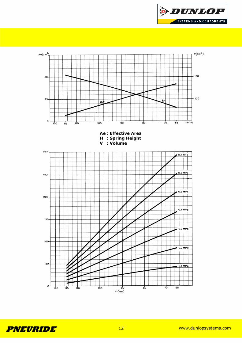
Ae : Effective Area H : Spring Height V : Volume
www.dunlopsystems.com 13 PNEURIDE
13
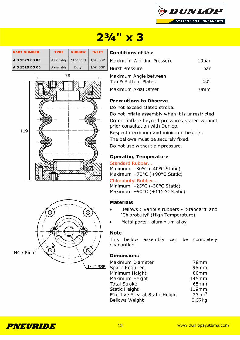
2¾" x 3 Conditions of Use
Precautions to Observe Do not exceed stated stroke. Do not inflate assembly when it is unrestricted. Do not inflate beyond pressures stated without prior consultation with Dunlop. Respect maximum and minimum heights. The bellows must be securely fixed. Do not use without air pressure. Operating Temperature Standard Rubber... Minimum –30°C (-40°C Static) Maximum +70°C (+90°C Static) Chlorobutyl Rubber... Minimum –25°C (-30°C Static) Maximum +90°C (+115°C Static) Materials • Bellows : Various rubbers - ‘Standard’ and
‘Chlorobutyl’ (High Temperature) • Metal parts : aluminium alloy Note This bellow assembly can be completely dismantled Dimensions Maximum Diameter 78mm Space Required 95mm Minimum Height 80mm Maximum Height 145mm Total Stroke 65mm Static Height 119mm Effective Area at Static Height 23cm2
Bellows Weight 0.57kg
Maximum Working Pressure 10bar
Burst Pressure bar
Maximum Angle between Top & Bottom Plates
10°
Maximum Axial Offset 10mm
119
PART NUMBER TYPE RUBBER INLET
A 3 1329 03 00 Assembly Standard 1/4” BSP
A 3 1329 B5 00 Assembly Butyl 1/4” BSP
78
1/4” BSP
M6 x 8mm
www.dunlopsystems.com 14 PNEURIDE
14
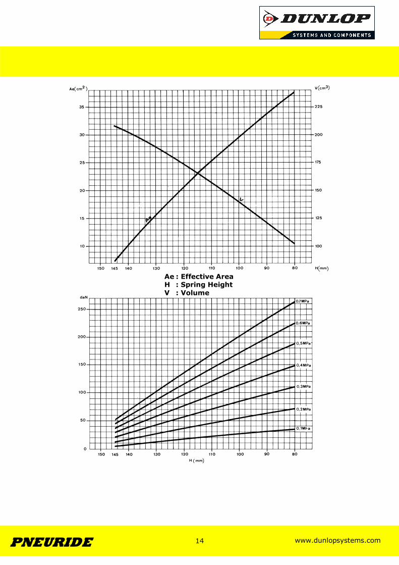
Ae : Effective Area H : Spring Height V : Volume
www.dunlopsystems.com 15 PNEURIDE
15
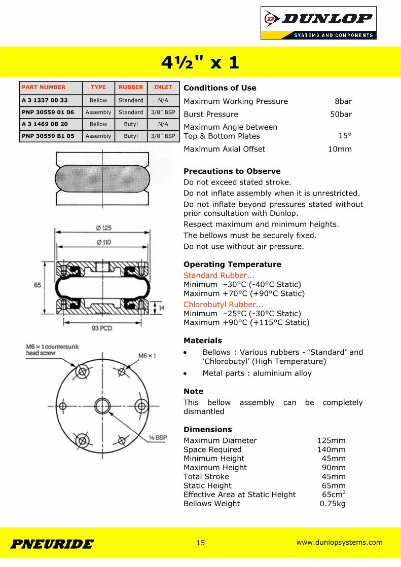
Conditions of Use
Precautions to Observe Do not exceed stated stroke. Do not inflate assembly when it is unrestricted. Do not inflate beyond pressures stated without prior consultation with Dunlop. Respect maximum and minimum heights. The bellows must be securely fixed. Do not use without air pressure. Operating Temperature Standard Rubber... Minimum –30°C (-40°C Static) Maximum +70°C (+90°C Static) Chlorobutyl Rubber... Minimum –25°C (-30°C Static) Maximum +90°C (+115°C Static) Materials • Bellows : Various rubbers - ‘Standard’ and
‘Chlorobutyl’ (High Temperature) • Metal parts : aluminium alloy Note This bellow assembly can be completely dismantled Dimensions Maximum Diameter 125mm Space Required 140mm Minimum Height 45mm Maximum Height 90mm Total Stroke 45mm Static Height 65mm Effective Area at Static Height 65cm2
Bellows Weight 0.75kg
4½" x 1
Maximum Working Pressure 8bar
Burst Pressure 50bar
Maximum Angle between Top & Bottom Plates
15°
Maximum Axial Offset 10mm
PART NUMBER TYPE RUBBER INLET
A 3 1337 00 32 Bellow Standard N/A
PNP 30559 01 06 Assembly Standard 3/8” BSP
A 3 1469 0B 20 Bellow Butyl N/A
PNP 30559 B1 05 Assembly Butyl 3/8” BSP
www.dunlopsystems.com 16 PNEURIDE
16
www.dunlopsystems.com 17 PNEURIDE
17
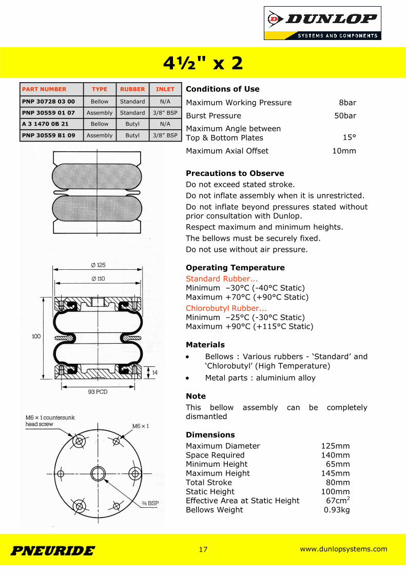
Conditions of Use
Precautions to Observe Do not exceed stated stroke. Do not inflate assembly when it is unrestricted. Do not inflate beyond pressures stated without prior consultation with Dunlop. Respect maximum and minimum heights. The bellows must be securely fixed. Do not use without air pressure. Operating Temperature Standard Rubber... Minimum –30°C (-40°C Static) Maximum +70°C (+90°C Static) Chlorobutyl Rubber... Minimum –25°C (-30°C Static) Maximum +90°C (+115°C Static) Materials • Bellows : Various rubbers - ‘Standard’ and
‘Chlorobutyl’ (High Temperature) • Metal parts : aluminium alloy Note This bellow assembly can be completely dismantled Dimensions Maximum Diameter 125mm Space Required 140mm Minimum Height 65mm Maximum Height 145mm Total Stroke 80mm Static Height 100mm Effective Area at Static Height 67cm2
Bellows Weight 0.93kg
4½" x 2
Maximum Working Pressure 8bar
Burst Pressure 50bar
Maximum Angle between Top & Bottom Plates
15°
Maximum Axial Offset 10mm
PART NUMBER TYPE RUBBER INLET
PNP 30728 03 00 Bellow Standard N/A
PNP 30559 01 07 Assembly Standard 3/8” BSP
A 3 1470 0B 21 Bellow Butyl N/A
PNP 30559 B1 09 Assembly Butyl 3/8” BSP
www.dunlopsystems.com 18 PNEURIDE
18
www.dunlopsystems.com 19 PNEURIDE
19
Conditions of Use
Precautions to Observe Do not exceed stated stroke. Do not inflate assembly when it is unrestricted. Do not inflate beyond pressures stated without prior consultation with Dunlop. Respect maximum and minimum heights. The bellows must be securely fixed. Do not use without air pressure. Operating Temperature Standard Rubber... Minimum –30°C (-40°C Static) Maximum +70°C (+90°C Static) Chlorobutyl Rubber... Minimum –25°C (-30°C Static) Maximum +90°C (+115°C Static) Materials • Bellows : Various rubbers - ‘Standard’ and
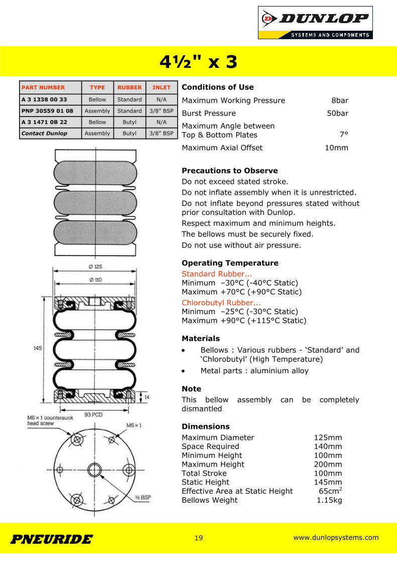
‘Chlorobutyl’ (High Temperature) • Metal parts : aluminium alloy Note This bellow assembly can be completely dismantled Dimensions Maximum Diameter 125mm Space Required 140mm Minimum Height 100mm Maximum Height 200mm Total Stroke 100mm Static Height 145mm Effective Area at Static Height 65cm2
Bellows Weight 1.15kg
4½" x 3
Maximum Working Pressure 8bar
Burst Pressure 50bar
Maximum Angle between Top & Bottom Plates
7°
Maximum Axial Offset 10mm
PART NUMBER TYPE RUBBER INLET
PNP 30559 01 08 Assembly Standard 3/8” BSP
A 3 1338 00 33 Bellow Standard N/A
A 3 1471 0B 22 Bellow Butyl N/A
Contact Dunlop Assembly Butyl 3/8” BSP
www.dunlopsystems.com 20 PNEURIDE
20
www.dunlopsystems.com 21 PNEURIDE
21
Conditions of Use
Precautions to Observe Do not exceed stated stroke. Do not inflate assembly when it is unrestricted. Do not inflate beyond pressures stated without prior consultation with Dunlop. Respect maximum and minimum heights. The bellows must be securely fixed. Do not use without air pressure. Operating Temperature Standard Rubber... Minimum –30°C (-40°C Static) Maximum +70°C (+90°C Static) Chlorobutyl Rubber... Minimum –25°C (-30°C Static) Maximum +90°C (+115°C Static) Materials • Bellows : Various rubbers - ‘Standard’ and
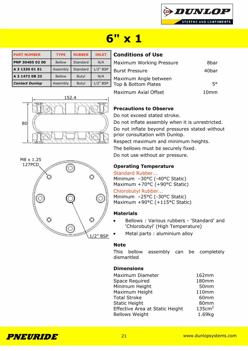
‘Chlorobutyl’ (High Temperature) • Metal parts : aluminium alloy Note This bellow assembly can be completely dismantled Dimensions Maximum Diameter 162mm Space Required 180mm Minimum Height 50mm Maximum Height 110mm Total Stroke 60mm Static Height 80mm Effective Area at Static Height 135cm2
Bellows Weight 1.69kg
6" x 1
Maximum Working Pressure 8bar
Burst Pressure 40bar
Maximum Angle between Top & Bottom Plates
5°
Maximum Axial Offset 10mm
PART NUMBER TYPE RUBBER INLET
A 3 1330 01 01 Assembly Standard 1/2” BSP
Contact Dunlop Assembly Butyl 1/2” BSP
PNP 30405 02 00 Bellow Standard N/A
A 3 1472 0B 23 Bellow Butyl N/A
152.4
80
1/2” BSP
M8 x 1.25 127PCD
www.dunlopsystems.com 22 PNEURIDE
22
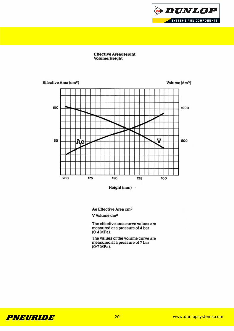
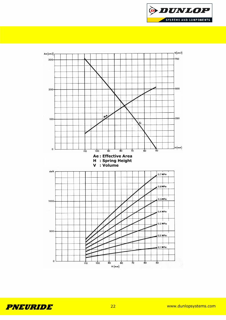
Ae : Effective Area H : Spring Height V : Volume
www.dunlopsystems.com 23 PNEURIDE
23
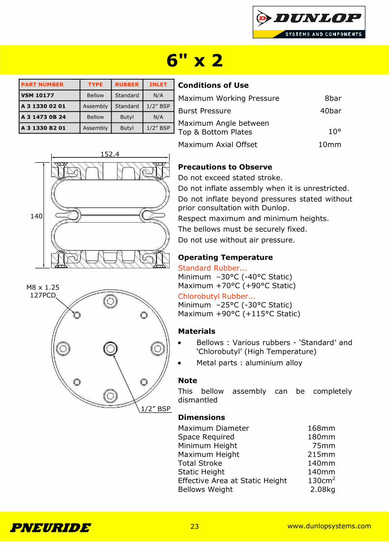
Conditions of Use
Precautions to Observe Do not exceed stated stroke. Do not inflate assembly when it is unrestricted. Do not inflate beyond pressures stated without prior consultation with Dunlop. Respect maximum and minimum heights. The bellows must be securely fixed. Do not use without air pressure. Operating Temperature Standard Rubber... Minimum –30°C (-40°C Static) Maximum +70°C (+90°C Static) Chlorobutyl Rubber... Minimum –25°C (-30°C Static) Maximum +90°C (+115°C Static) Materials • Bellows : Various rubbers - ‘Standard’ and
‘Chlorobutyl’ (High Temperature) • Metal parts : aluminium alloy Note This bellow assembly can be completely dismantled Dimensions Maximum Diameter 168mm Space Required 180mm Minimum Height 75mm Maximum Height 215mm Total Stroke 140mm Static Height 140mm Effective Area at Static Height 130cm2
Bellows Weight 2.08kg
6" x 2
Maximum Working Pressure 8bar
Burst Pressure 40bar
Maximum Angle between Top & Bottom Plates
10°
Maximum Axial Offset 10mm
PART NUMBER TYPE RUBBER INLET
A 3 1330 02 01 Assembly Standard 1/2” BSP
A 3 1330 B2 01 Assembly Butyl 1/2” BSP
VSM 10177 Bellow Standard N/A
A 3 1473 0B 24 Bellow Butyl N/A
1/2” BSP
M8 x 1.25 127PCD
152.4
140

www.dunlopsystems.com 24 PNEURIDE
24
Ae : Effective Area H : Spring Height V : Volume
www.dunlopsystems.com 25 PNEURIDE
25
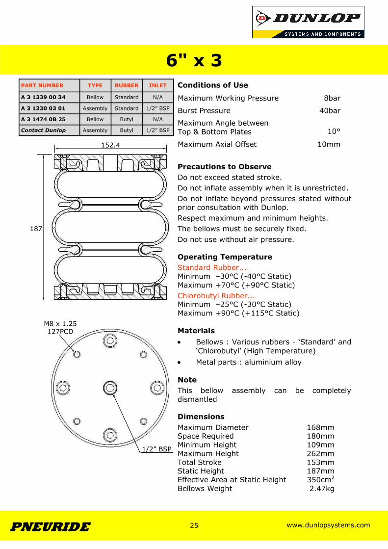
Conditions of Use
Precautions to Observe Do not exceed stated stroke. Do not inflate assembly when it is unrestricted. Do not inflate beyond pressures stated without prior consultation with Dunlop. Respect maximum and minimum heights. The bellows must be securely fixed. Do not use without air pressure. Operating Temperature Standard Rubber... Minimum –30°C (-40°C Static) Maximum +70°C (+90°C Static) Chlorobutyl Rubber... Minimum –25°C (-30°C Static) Maximum +90°C (+115°C Static) Materials • Bellows : Various rubbers - ‘Standard’ and
‘Chlorobutyl’ (High Temperature) • Metal parts : aluminium alloy Note This bellow assembly can be completely dismantled Dimensions Maximum Diameter 168mm Space Required 180mm Minimum Height 109mm Maximum Height 262mm Total Stroke 153mm Static Height 187mm Effective Area at Static Height 350cm2
Bellows Weight 2.47kg
6" x 3
Maximum Working Pressure 8bar
Burst Pressure 40bar
Maximum Angle between Top & Bottom Plates
10°
Maximum Axial Offset 10mm
PART NUMBER TYPE RUBBER INLET
A 3 1330 03 01 Assembly Standard 1/2” BSP
A 3 1339 00 34 Bellow Standard N/A
A 3 1474 0B 25 Bellow Butyl N/A
Contact Dunlop Assembly Butyl 1/2” BSP
187
152.4
1/2” BSP
M8 x 1.25 127PCD
www.dunlopsystems.com 26 PNEURIDE
26
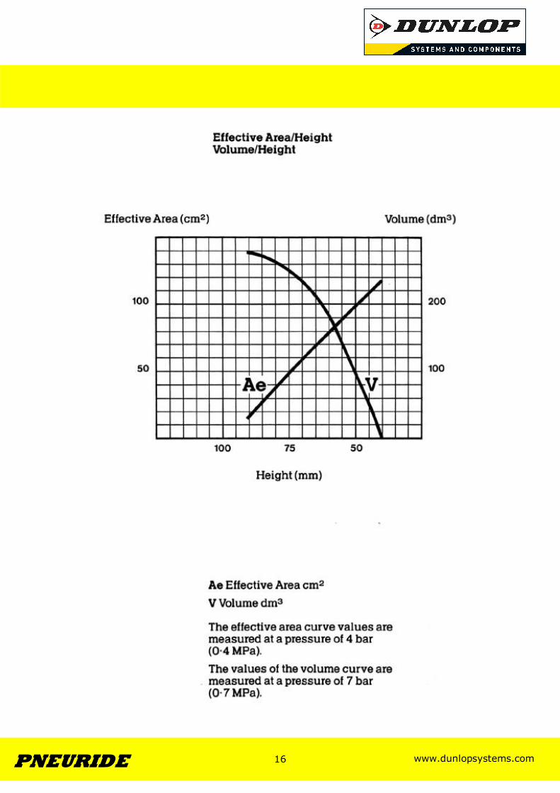
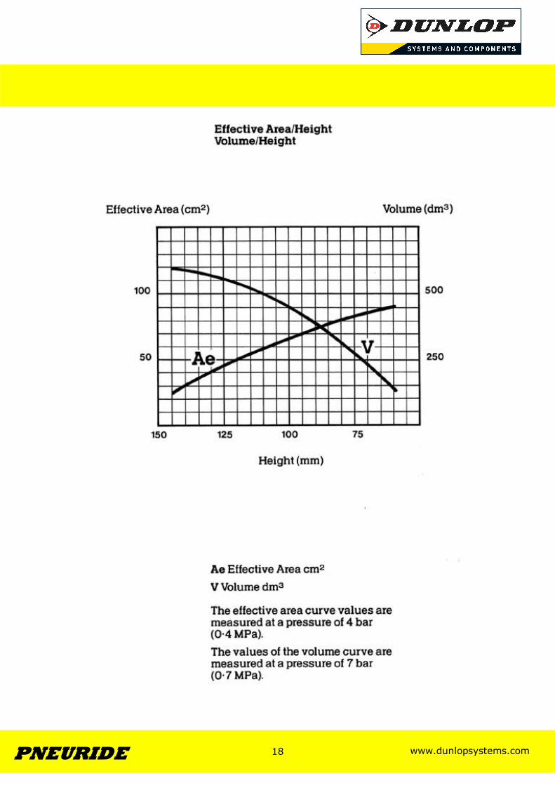
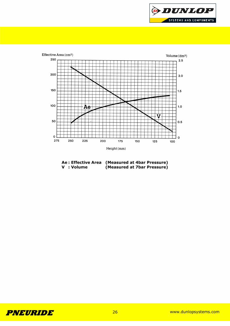
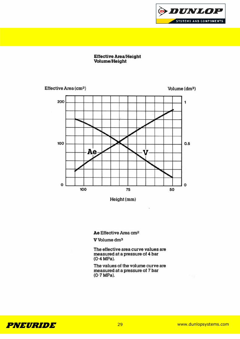
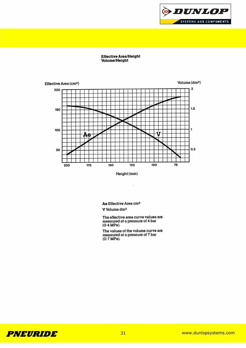
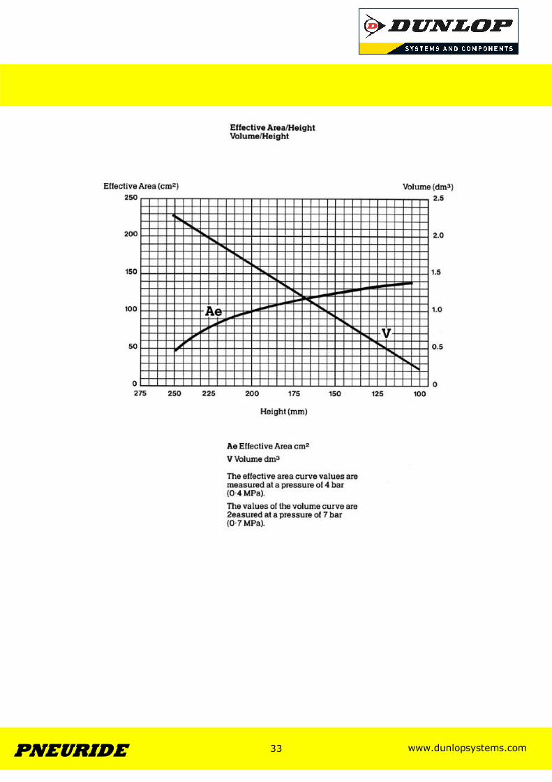
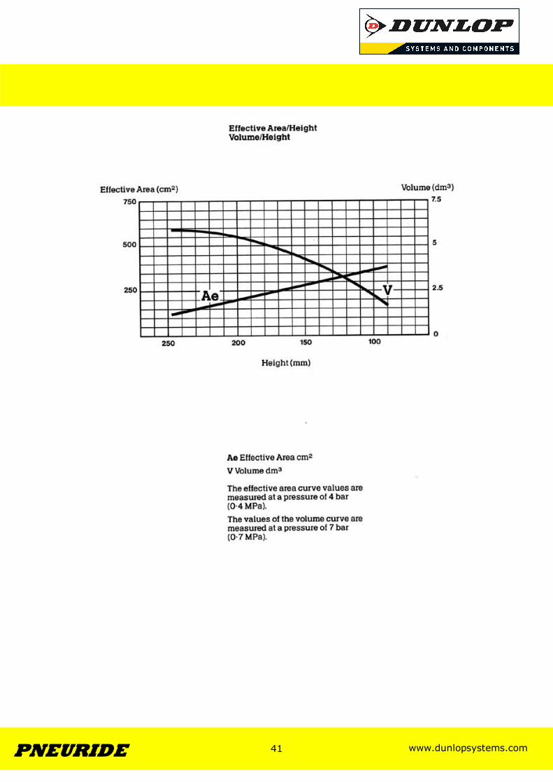
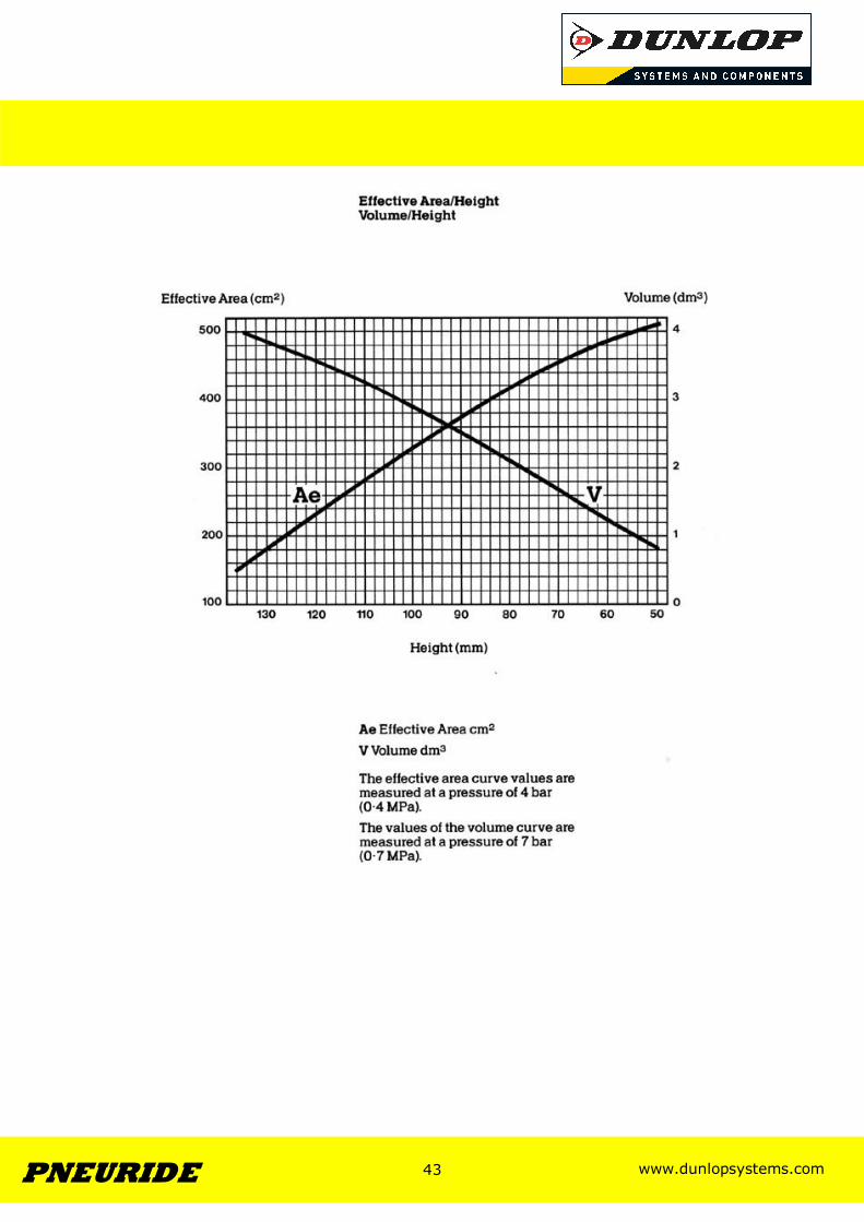
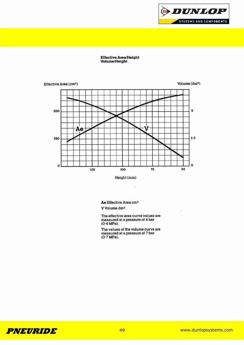
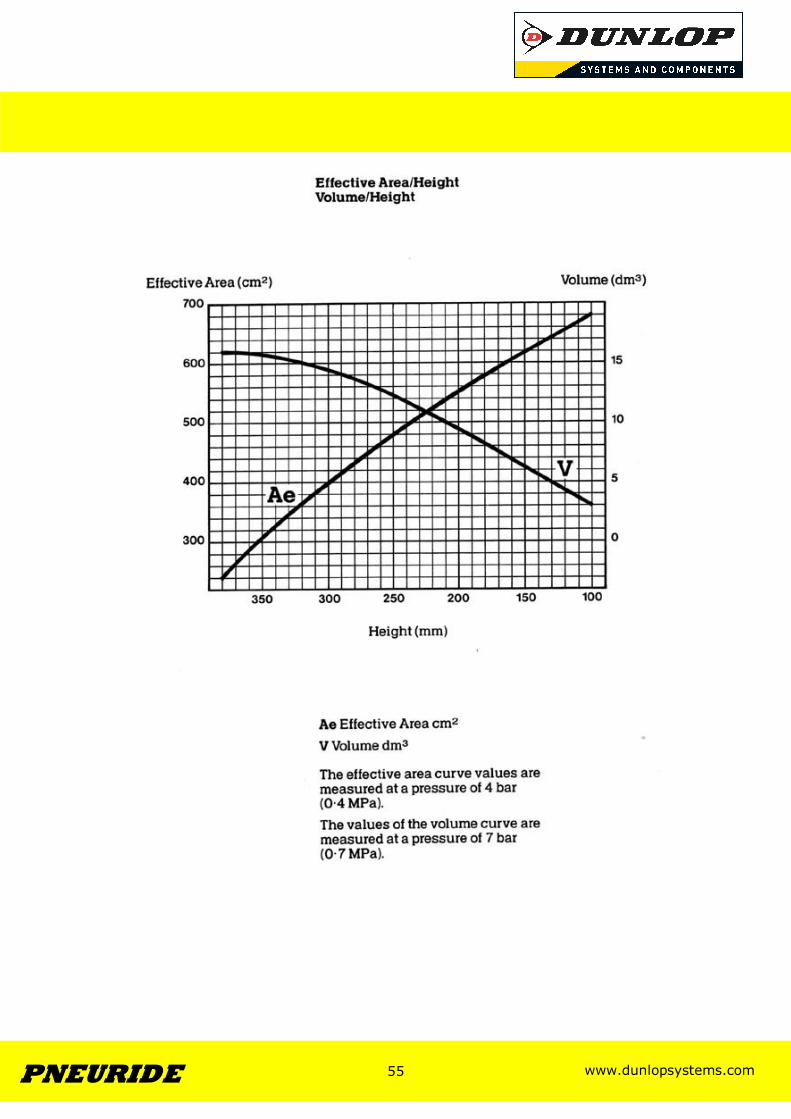
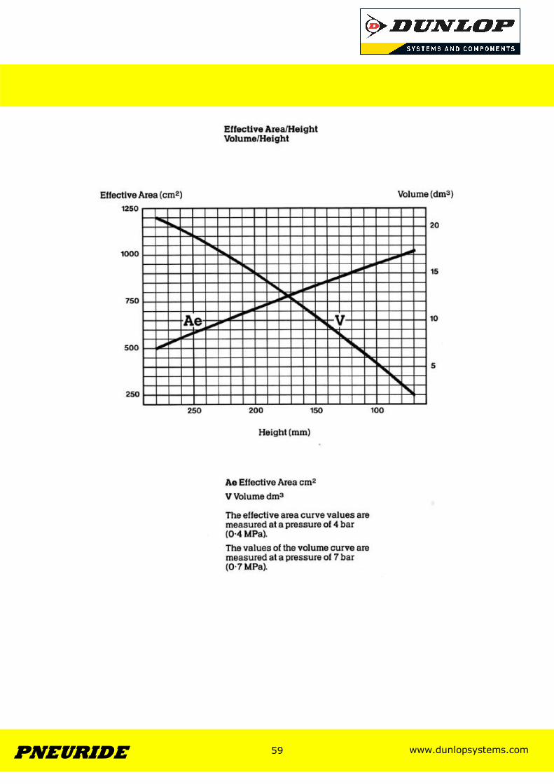
Ae : Effective Area (Measured at 4bar Pressure) V : Volume (Measured at 7bar Pressure)
www.dunlopsystems.com 27 PNEURIDE
27
Section 2
Bellows with Steel Clamping
Plates
www.dunlopsystems.com 28 PNEURIDE
28
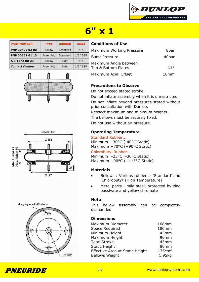
Conditions of Use
Precautions to Observe Do not exceed stated stroke. Do not inflate assembly when it is unrestricted. Do not inflate beyond pressures stated without prior consultation with Dunlop. Respect maximum and minimum heights. The bellows must be securely fixed. Do not use without air pressure. Operating Temperature Standard Rubber... Minimum –30°C (-40°C Static) Maximum +70°C (+90°C Static) Chlorobutyl Rubber... Minimum –25°C (-30°C Static) Maximum +90°C (+115°C Static) Materials • Bellows : Various rubbers - ‘Standard’ and
‘Chlorobutyl’ (High Temperature) • Metal parts : mild steel, protected by zinc
passivate and yellow chromate Note This bellow assembly can be completely dismantled Dimensions Maximum Diameter 168mm Space Required 180mm Minimum Height 45mm Maximum Height 90mm Total Stroke 45mm Static Height 80mm Effective Area at Static Height 135cm2
Bellows Weight 1.95kg
6" x 1
Maximum Working Pressure 8bar
Burst Pressure 40bar
Maximum Angle between Top & Bottom Plates
15°
Maximum Axial Offset 10mm
PART NUMBER TYPE RUBBER INLET
PNP 30405 02 00 Bellow Standard N/A
PNP 30551 01 13 Assembly Standard 1/2” BSP
A 3 1472 0B 23 Bellow Butyl N/A
Contact Dunlop Assembly Butyl 1/2” BSP
Min
. Hei
ght 4
5 M
ax. H
eigh
t 90
www.dunlopsystems.com 29 PNEURIDE
29
www.dunlopsystems.com 30 PNEURIDE
30
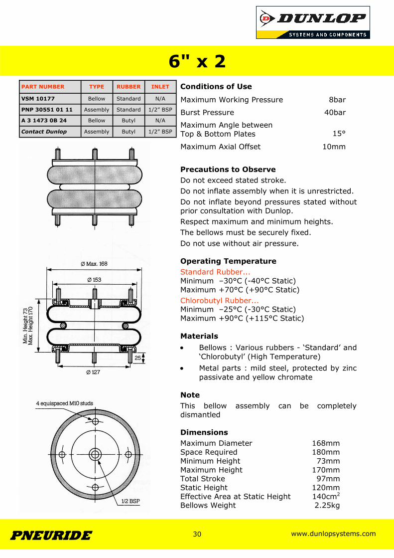
Conditions of Use
Precautions to Observe Do not exceed stated stroke. Do not inflate assembly when it is unrestricted. Do not inflate beyond pressures stated without prior consultation with Dunlop. Respect maximum and minimum heights. The bellows must be securely fixed. Do not use without air pressure. Operating Temperature Standard Rubber... Minimum –30°C (-40°C Static) Maximum +70°C (+90°C Static) Chlorobutyl Rubber... Minimum –25°C (-30°C Static) Maximum +90°C (+115°C Static) Materials • Bellows : Various rubbers - ‘Standard’ and
‘Chlorobutyl’ (High Temperature) • Metal parts : mild steel, protected by zinc
passivate and yellow chromate Note This bellow assembly can be completely dismantled Dimensions Maximum Diameter 168mm Space Required 180mm Minimum Height 73mm Maximum Height 170mm Total Stroke 97mm Static Height 120mm Effective Area at Static Height 140cm2
Bellows Weight 2.25kg
6" x 2
Maximum Working Pressure 8bar
Burst Pressure 40bar
Maximum Angle between Top & Bottom Plates
15°
Maximum Axial Offset 10mm
PART NUMBER TYPE RUBBER INLET
VSM 10177 Bellow Standard N/A
PNP 30551 01 11 Assembly Standard 1/2” BSP
A 3 1473 0B 24 Bellow Butyl N/A
Contact Dunlop Assembly Butyl 1/2” BSP
www.dunlopsystems.com 31 PNEURIDE
31
www.dunlopsystems.com 32 PNEURIDE
32
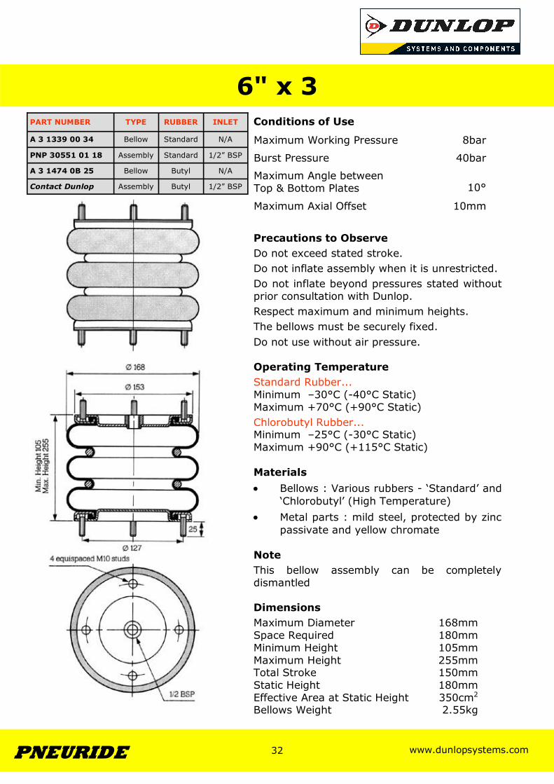
Conditions of Use
Precautions to Observe Do not exceed stated stroke. Do not inflate assembly when it is unrestricted. Do not inflate beyond pressures stated without prior consultation with Dunlop. Respect maximum and minimum heights. The bellows must be securely fixed. Do not use without air pressure. Operating Temperature Standard Rubber... Minimum –30°C (-40°C Static) Maximum +70°C (+90°C Static) Chlorobutyl Rubber... Minimum –25°C (-30°C Static) Maximum +90°C (+115°C Static) Materials • Bellows : Various rubbers - ‘Standard’ and
‘Chlorobutyl’ (High Temperature) • Metal parts : mild steel, protected by zinc
passivate and yellow chromate Note This bellow assembly can be completely dismantled Dimensions Maximum Diameter 168mm Space Required 180mm Minimum Height 105mm Maximum Height 255mm Total Stroke 150mm Static Height 180mm Effective Area at Static Height 350cm2
Bellows Weight 2.55kg
6" x 3
Maximum Working Pressure 8bar
Burst Pressure 40bar
Maximum Angle between Top & Bottom Plates
10°
Maximum Axial Offset 10mm
PART NUMBER TYPE RUBBER INLET
A 3 1339 00 34 Bellow Standard N/A
PNP 30551 01 18 Assembly Standard 1/2” BSP
A 3 1474 0B 25 Bellow Butyl N/A
Contact Dunlop Assembly Butyl 1/2” BSP
www.dunlopsystems.com 33 PNEURIDE
33
www.dunlopsystems.com 34 PNEURIDE
34
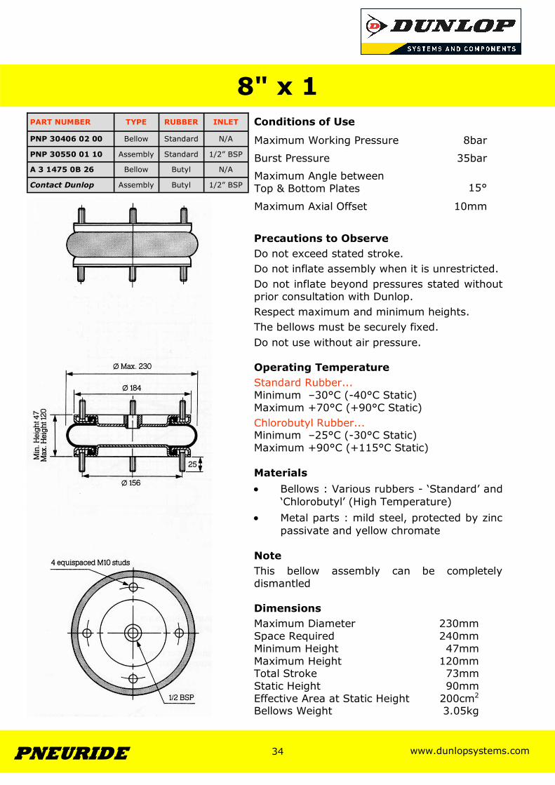
Conditions of Use
Precautions to Observe Do not exceed stated stroke. Do not inflate assembly when it is unrestricted. Do not inflate beyond pressures stated without prior consultation with Dunlop. Respect maximum and minimum heights. The bellows must be securely fixed. Do not use without air pressure. Operating Temperature Standard Rubber... Minimum –30°C (-40°C Static) Maximum +70°C (+90°C Static) Chlorobutyl Rubber... Minimum –25°C (-30°C Static) Maximum +90°C (+115°C Static) Materials • Bellows : Various rubbers - ‘Standard’ and
‘Chlorobutyl’ (High Temperature) • Metal parts : mild steel, protected by zinc
passivate and yellow chromate Note This bellow assembly can be completely dismantled Dimensions Maximum Diameter 230mm Space Required 240mm Minimum Height 47mm Maximum Height 120mm Total Stroke 73mm Static Height 90mm Effective Area at Static Height 200cm2
Bellows Weight 3.05kg
8" x 1
Maximum Working Pressure 8bar
Burst Pressure 35bar
Maximum Angle between Top & Bottom Plates
15°
Maximum Axial Offset 10mm
PART NUMBER TYPE RUBBER INLET
PNP 30406 02 00 Bellow Standard N/A
PNP 30550 01 10 Assembly Standard 1/2” BSP
A 3 1475 0B 26 Bellow Butyl N/A
Contact Dunlop Assembly Butyl 1/2” BSP
www.dunlopsystems.com 35 PNEURIDE
35
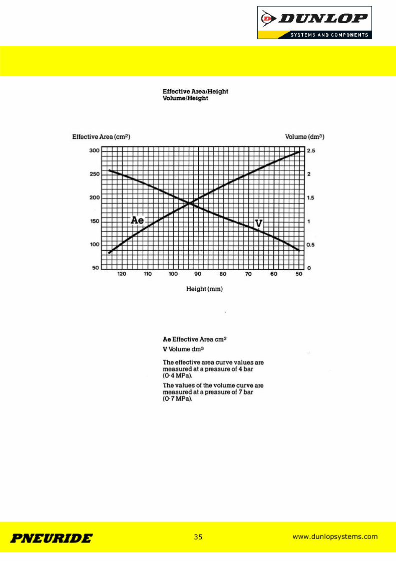
www.dunlopsystems.com 36 PNEURIDE
36
Conditions of Use
Precautions to Observe Do not exceed stated stroke. Do not inflate assembly when it is unrestricted. Do not inflate beyond pressures stated without prior consultation with Dunlop. Respect maximum and minimum heights. The bellows must be securely fixed. Do not use without air pressure. Operating Temperature Standard Rubber... Minimum –30°C (-40°C Static) Maximum +70°C (+90°C Static) Chlorobutyl Rubber... Minimum –25°C (-30°C Static) Maximum +90°C (+115°C Static) Materials • Bellows : Various rubbers - ‘Standard’ and
‘Chlorobutyl’ (High Temperature) • Metal parts : mild steel, protected by zinc
passivate and yellow chromate Note This bellow assembly can be completely dismantled Dimensions Maximum Diameter 230mm Space Required 240mm Minimum Height 72mm Maximum Height 225mm Total Stroke 153mm Static Height 150mm Effective Area at Static Height 220cm2
Bellows Weight 3.75kg
8" x 2
Maximum Working Pressure 8bar
Burst Pressure 35bar
Maximum Angle between Top & Bottom Plates
15°
Maximum Axial Offset 10mm
PART NUMBER TYPE RUBBER INLET
VSM 10180 Bellow Standard N/A
PNP 30550 01 12 Assembly Standard 1/2” BSP
A 3 1476 0B 27 Bellow Butyl N/A
PNP 30550 01 11 Assembly Butyl 1/2” BSP
www.dunlopsystems.com 37 PNEURIDE
37
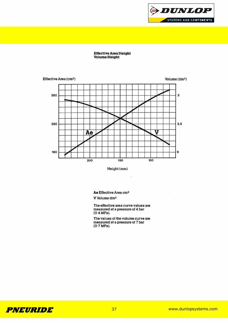
www.dunlopsystems.com 38 PNEURIDE
38
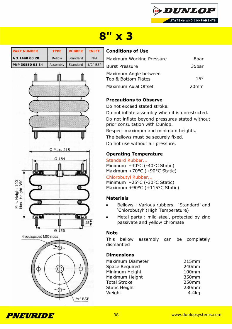
Conditions of Use
Precautions to Observe Do not exceed stated stroke. Do not inflate assembly when it is unrestricted. Do not inflate beyond pressures stated without prior consultation with Dunlop. Respect maximum and minimum heights. The bellows must be securely fixed. Do not use without air pressure. Operating Temperature Standard Rubber... Minimum –30°C (-40°C Static) Maximum +70°C (+90°C Static) Chlorobutyl Rubber... Minimum –25°C (-30°C Static) Maximum +90°C (+115°C Static) Materials • Bellows : Various rubbers - ‘Standard’ and
‘Chlorobutyl’ (High Temperature) • Metal parts : mild steel, protected by zinc
passivate and yellow chromate Note This bellow assembly can be completely dismantled Dimensions Maximum Diameter 215mm Space Required 240mm Minimum Height 100mm Maximum Height 350mm Total Stroke 250mm Static Height 230mm Weight 4.4kg
8" x 3
Maximum Working Pressure 8bar
Burst Pressure 35bar
Maximum Angle between Top & Bottom Plates
15°
Maximum Axial Offset 20mm
PART NUMBER TYPE RUBBER INLET
A 3 1440 00 20 Bellow Standard N/A
PNP 30550 01 34 Assembly Standard 1/2” BSP
Ø 184
Ø Max. 215
½” BSP
Min
. H
eigh
t 10
0 M
ax.
Hei
ght
350
Ø 156
www.dunlopsystems.com 39 PNEURIDE
39
www.dunlopsystems.com 40 PNEURIDE
40
Conditions of Use
Precautions to Observe Do not exceed stated stroke. Do not inflate assembly when it is unrestricted. Do not inflate beyond pressures stated without prior consultation with Dunlop. Respect maximum and minimum heights. The bellows must be securely fixed. Do not use without air pressure. Operating Temperature Standard Rubber... Minimum –30°C (-40°C Static) Maximum +70°C (+90°C Static) Chlorobutyl Rubber... Minimum –25°C (-30°C Static) Maximum +90°C (+115°C Static) Materials • Bellows : Various rubbers - ‘Standard’ and
‘Chlorobutyl’ (High Temperature) • Metal parts : mild steel, protected by zinc
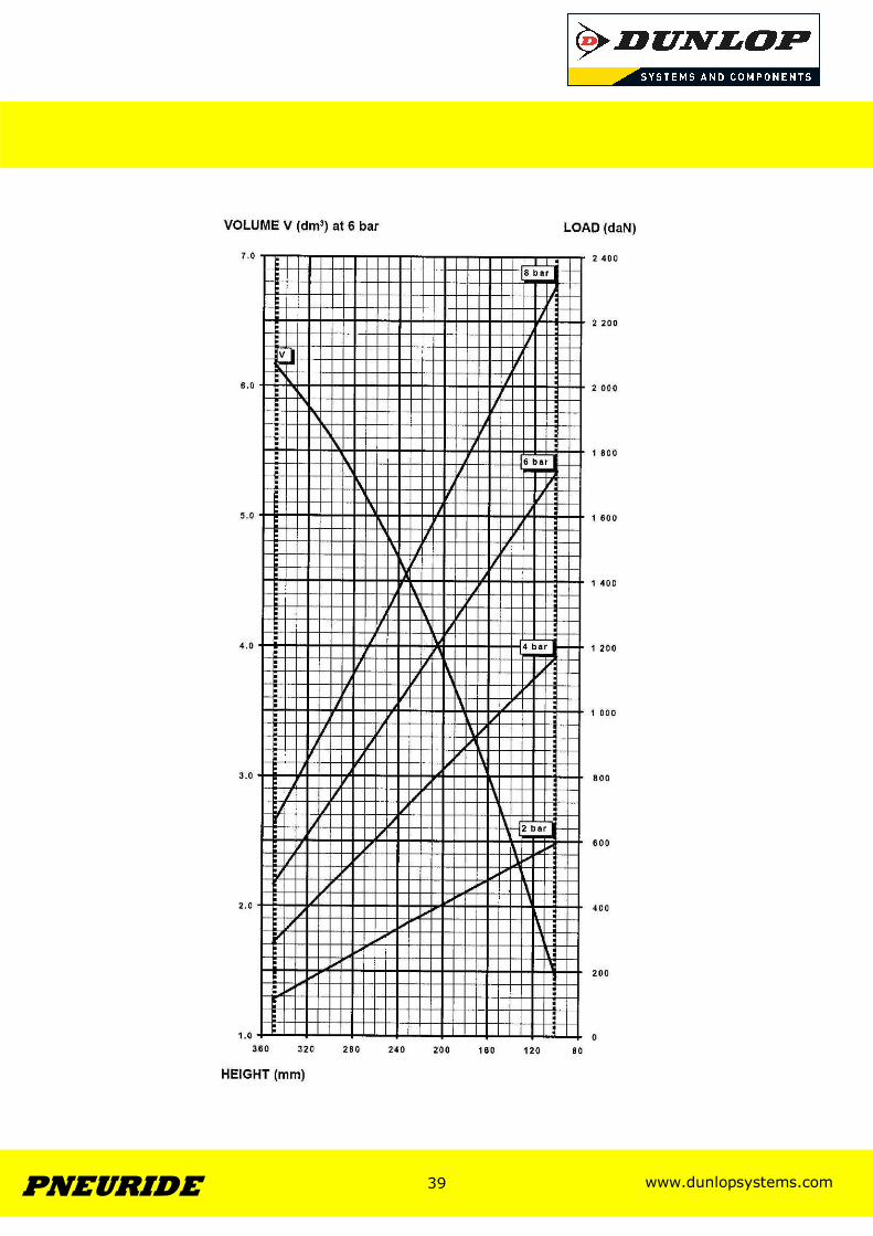
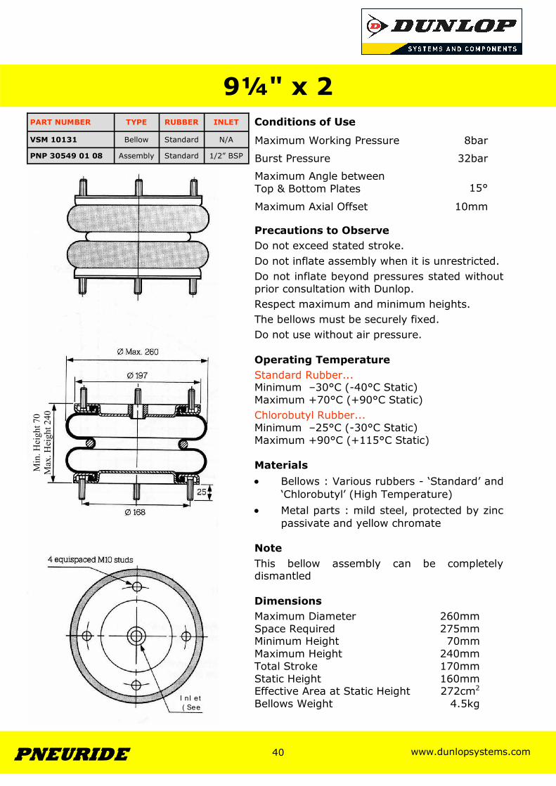
passivate and yellow chromate Note This bellow assembly can be completely dismantled Dimensions Maximum Diameter 260mm Space Required 275mm Minimum Height 70mm Maximum Height 240mm Total Stroke 170mm Static Height 160mm Effective Area at Static Height 272cm2
Bellows Weight 4.5kg
9¼" x 2
Maximum Working Pressure 8bar
Burst Pressure 32bar
Maximum Angle between Top & Bottom Plates
15°
Maximum Axial Offset 10mm
PART NUMBER TYPE RUBBER INLET
VSM 10131 Bellow Standard N/A
PNP 30549 01 08 Assembly Standard 1/2” BSP
½” BSP
Min
. Hei
ght 7
0 M
ax. H
eigh
t 240
I n l et ( See
www.dunlopsystems.com 41 PNEURIDE
41
www.dunlopsystems.com 42 PNEURIDE
42
Conditions of Use
Precautions to Observe Do not exceed stated stroke. Do not inflate assembly when it is unrestricted. Do not inflate beyond pressures stated without prior consultation with Dunlop. Respect maximum and minimum heights. The bellows must be securely fixed. Do not use without air pressure. Operating Temperature Standard Rubber... Minimum –30°C (-40°C Static) Maximum +70°C (+90°C Static) Chlorobutyl Rubber... Minimum –25°C (-30°C Static) Maximum +90°C (+115°C Static) Materials • Bellows : Various rubbers - ‘Standard’ and
‘Chlorobutyl’ (High Temperature) • Metal parts : mild steel, protected by zinc
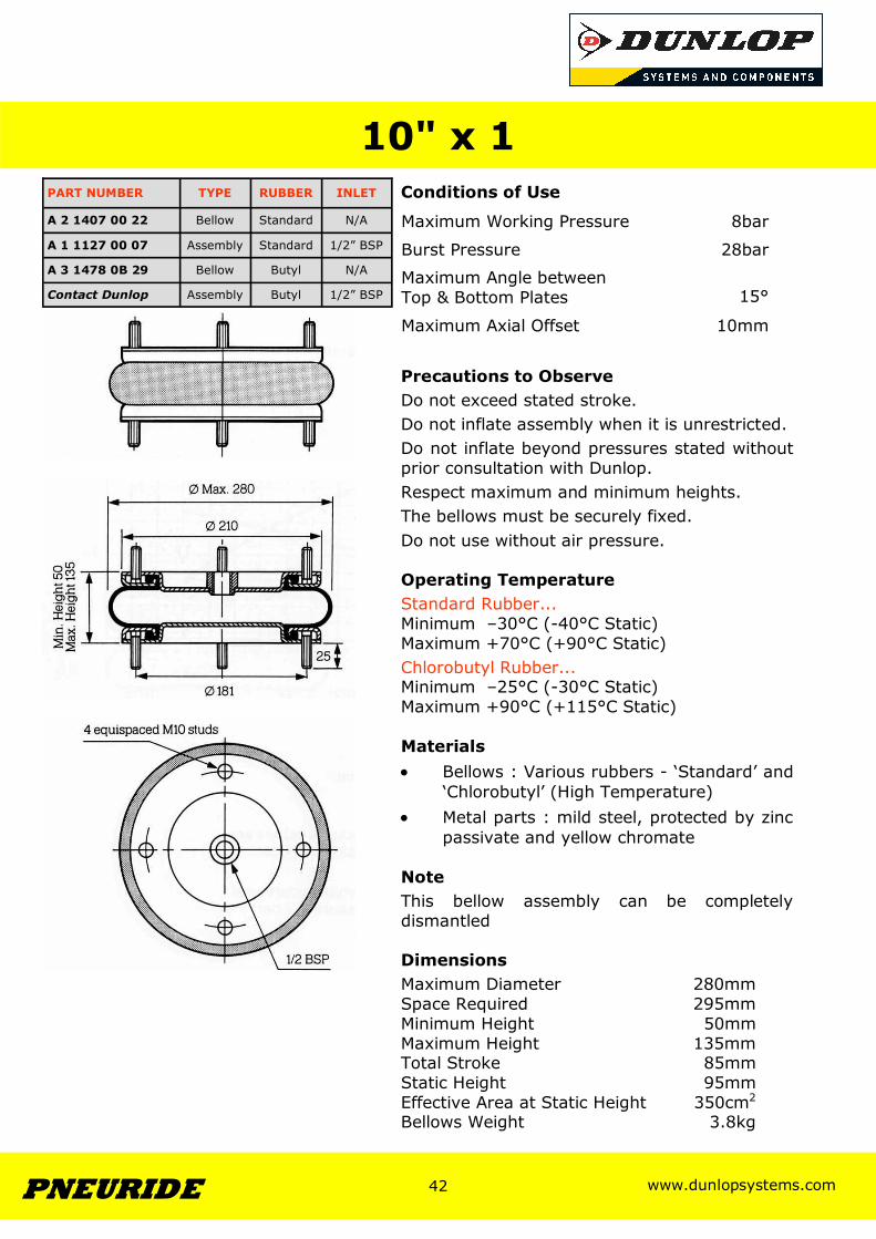
passivate and yellow chromate Note This bellow assembly can be completely dismantled Dimensions Maximum Diameter 280mm Space Required 295mm Minimum Height 50mm Maximum Height 135mm Total Stroke 85mm Static Height 95mm Effective Area at Static Height 350cm2
Bellows Weight 3.8kg
10" x 1
Maximum Working Pressure 8bar
Burst Pressure 28bar
Maximum Angle between Top & Bottom Plates
15°
Maximum Axial Offset 10mm
PART NUMBER TYPE RUBBER INLET
A 2 1407 00 22 Bellow Standard N/A
A 3 1478 0B 29 Bellow Butyl N/A
A 1 1127 00 07 Assembly Standard 1/2” BSP
Contact Dunlop Assembly Butyl 1/2” BSP
www.dunlopsystems.com 43 PNEURIDE
43
www.dunlopsystems.com 44 PNEURIDE
44
Conditions of Use
Precautions to Observe Do not exceed stated stroke. Do not inflate assembly when it is unrestricted. Do not inflate beyond pressures stated without prior consultation with Dunlop. Respect maximum and minimum heights. The bellows must be securely fixed. Do not use without air pressure. Operating Temperature Standard Rubber... Minimum –30°C (-40°C Static) Maximum +70°C (+90°C Static) Chlorobutyl Rubber... Minimum –25°C (-30°C Static) Maximum +90°C (+115°C Static) Materials • Bellows : Various rubbers - ‘Standard’ and
‘Chlorobutyl’ (High Temperature) • Metal parts : mild steel, protected by zinc
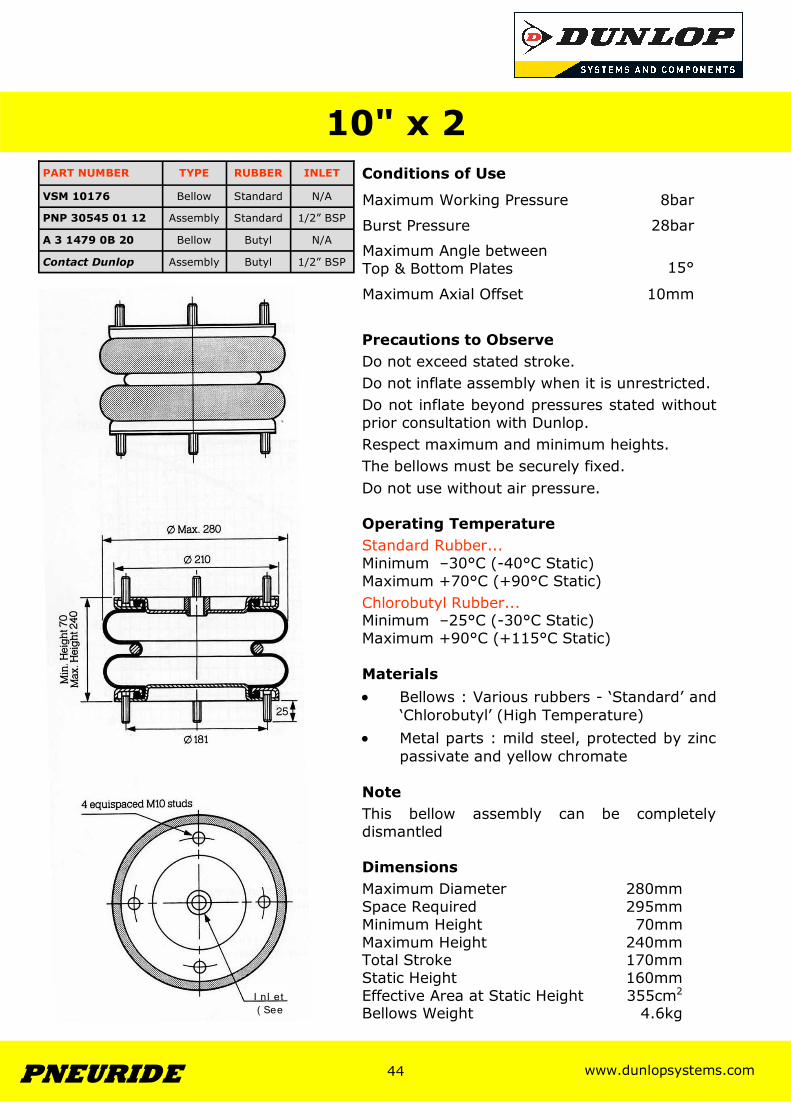
passivate and yellow chromate Note This bellow assembly can be completely dismantled Dimensions Maximum Diameter 280mm Space Required 295mm Minimum Height 70mm Maximum Height 240mm Total Stroke 170mm Static Height 160mm Effective Area at Static Height 355cm2
Bellows Weight 4.6kg
10" x 2
Maximum Working Pressure 8bar
Burst Pressure 28bar
Maximum Angle between Top & Bottom Plates
15°
Maximum Axial Offset 10mm
PART NUMBER TYPE RUBBER INLET
VSM 10176 Bellow Standard N/A
PNP 30545 01 12 Assembly Standard 1/2” BSP
A 3 1479 0B 20 Bellow Butyl N/A
Contact Dunlop Assembly Butyl 1/2” BSP
I n l et ( See
www.dunlopsystems.com 45 PNEURIDE
45
www.dunlopsystems.com 46 PNEURIDE
46
Conditions of Use
Precautions to Observe Do not exceed stated stroke. Do not inflate assembly when it is unrestricted. Do not inflate beyond pressures stated without prior consultation with Dunlop. Respect maximum and minimum heights. The bellows must be securely fixed. Do not use without air pressure. Operating Temperature Standard Rubber... Minimum –30°C (-40°C Static) Maximum +70°C (+90°C Static) Chlorobutyl Rubber... Minimum –25°C (-30°C Static) Maximum +90°C (+115°C Static) Materials • Bellows : Various rubbers - ‘Standard’ and
‘Chlorobutyl’ (High Temperature) • Metal parts : mild steel, protected by zinc
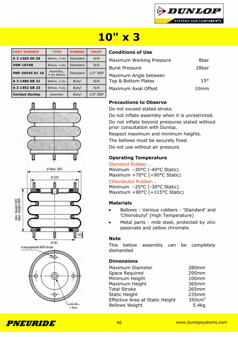
passivate and yellow chromate Note This bellow assembly can be completely dismantled Dimensions Maximum Diameter 280mm Space Required 295mm Minimum Height 100mm Maximum Height 365mm Total Stroke 265mm Static Height 235mm Effective Area at Static Height 350cm2
Bellows Weight 5.4kg
10" x 3
Maximum Working Pressure 8bar
Burst Pressure 28bar
Maximum Angle between Top & Bottom Plates
15°
Maximum Axial Offset 10mm
PART NUMBER TYPE RUBBER INLET
A 3 1465 00 26 Bellow, 2 ply Standard N/A
VSM 10798 Bellow, 4 ply Standard N/A
PNP 30545 01 10 Assembly, 4 ply Bellow Standard 1/2” BSP
A 3 1480 0B 21 Bellow, 2 ply Butyl N/A
A 3 1492 0B 23 Bellow, 4 ply Butyl N/A
Contact Dunlop Assembly Butyl 1/2” BSP
I n l et ( See

www.dunlopsystems.com 47 PNEURIDE
47
www.dunlopsystems.com 48 PNEURIDE
48
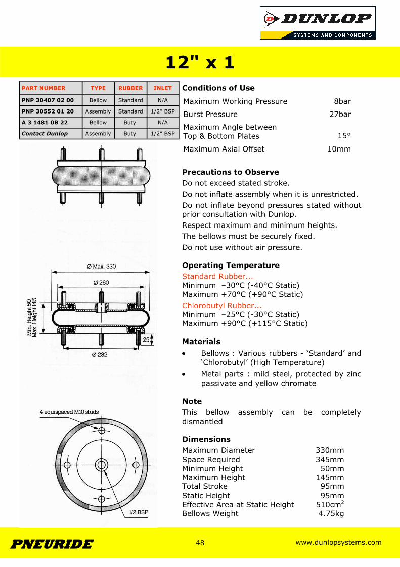
Conditions of Use
Precautions to Observe Do not exceed stated stroke. Do not inflate assembly when it is unrestricted. Do not inflate beyond pressures stated without prior consultation with Dunlop. Respect maximum and minimum heights. The bellows must be securely fixed. Do not use without air pressure. Operating Temperature Standard Rubber... Minimum –30°C (-40°C Static) Maximum +70°C (+90°C Static) Chlorobutyl Rubber... Minimum –25°C (-30°C Static) Maximum +90°C (+115°C Static) Materials • Bellows : Various rubbers - ‘Standard’ and
‘Chlorobutyl’ (High Temperature) • Metal parts : mild steel, protected by zinc
passivate and yellow chromate Note This bellow assembly can be completely dismantled Dimensions Maximum Diameter 330mm Space Required 345mm Minimum Height 50mm Maximum Height 145mm Total Stroke 95mm Static Height 95mm Effective Area at Static Height 510cm2
Bellows Weight 4.75kg
12" x 1
Maximum Working Pressure 8bar
Burst Pressure 27bar
Maximum Angle between Top & Bottom Plates
15°
Maximum Axial Offset 10mm
PART NUMBER TYPE RUBBER INLET
PNP 30407 02 00 Bellow Standard N/A
PNP 30552 01 20 Assembly Standard 1/2” BSP
A 3 1481 0B 22 Bellow Butyl N/A
Contact Dunlop Assembly Butyl 1/2” BSP
www.dunlopsystems.com 49 PNEURIDE
49
www.dunlopsystems.com 50 PNEURIDE
50
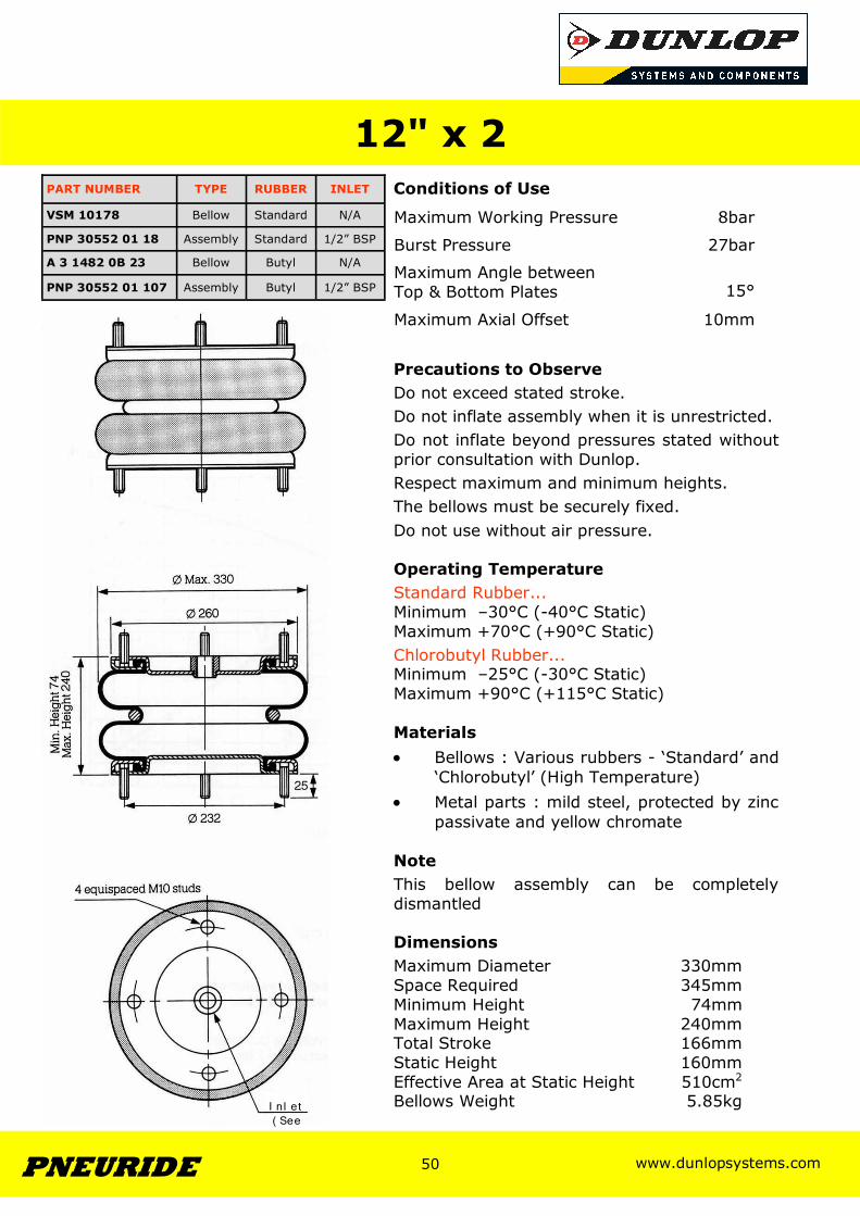
Conditions of Use
Precautions to Observe Do not exceed stated stroke. Do not inflate assembly when it is unrestricted. Do not inflate beyond pressures stated without prior consultation with Dunlop. Respect maximum and minimum heights. The bellows must be securely fixed. Do not use without air pressure. Operating Temperature Standard Rubber... Minimum –30°C (-40°C Static) Maximum +70°C (+90°C Static) Chlorobutyl Rubber... Minimum –25°C (-30°C Static) Maximum +90°C (+115°C Static) Materials • Bellows : Various rubbers - ‘Standard’ and
‘Chlorobutyl’ (High Temperature) • Metal parts : mild steel, protected by zinc
passivate and yellow chromate Note This bellow assembly can be completely dismantled Dimensions Maximum Diameter 330mm Space Required 345mm Minimum Height 74mm Maximum Height 240mm Total Stroke 166mm Static Height 160mm Effective Area at Static Height 510cm2
Bellows Weight 5.85kg
12" x 2
Maximum Working Pressure 8bar
Burst Pressure 27bar
Maximum Angle between Top & Bottom Plates
15°
Maximum Axial Offset 10mm
PART NUMBER TYPE RUBBER INLET
VSM 10178 Bellow Standard N/A
PNP 30552 01 18 Assembly Standard 1/2” BSP
A 3 1482 0B 23 Bellow Butyl N/A
PNP 30552 01 107 Assembly Butyl 1/2” BSP
I n l et ( See

www.dunlopsystems.com 51 PNEURIDE
51
www.dunlopsystems.com 52 PNEURIDE
52
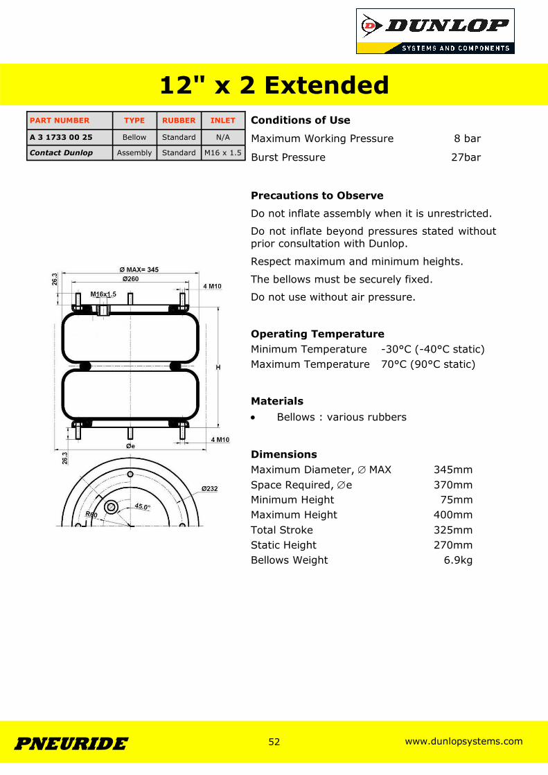
12" x 2 Extended Conditions of Use
Precautions to Observe
Do not inflate assembly when it is unrestricted.
Do not inflate beyond pressures stated without prior consultation with Dunlop.
Respect maximum and minimum heights.
The bellows must be securely fixed.
Do not use without air pressure. Operating Temperature Minimum Temperature -30°C (-40°C static) Maximum Temperature 70°C (90°C static) Materials • Bellows : various rubbers Dimensions Maximum Diameter, ∅ MAX 345mm Space Required, ∅e 370mm Minimum Height 75mm Maximum Height 400mm Total Stroke 325mm Static Height 270mm Bellows Weight 6.9kg
Burst Pressure 27bar
Maximum Working Pressure 8 bar
PART NUMBER TYPE RUBBER INLET
A 3 1733 00 25 Bellow Standard N/A
Contact Dunlop Assembly Standard M16 x 1.5
= 345
www.dunlopsystems.com 53 PNEURIDE
53
www.dunlopsystems.com 54 PNEURIDE
54
Conditions of Use
Precautions to Observe Do not exceed stated stroke. Do not inflate assembly when it is unrestricted. Do not inflate beyond pressures stated without prior consultation with Dunlop. Respect maximum and minimum heights. The bellows must be securely fixed. Do not use without air pressure. Operating Temperature Standard Rubber... Minimum –30°C (-40°C Static) Maximum +70°C (+90°C Static) Chlorobutyl Rubber... Minimum –25°C (-30°C Static) Maximum +90°C (+115°C Static) Materials • Bellows : Various rubbers - ‘Standard’ and
‘Chlorobutyl’ (High Temperature) • Metal parts : mild steel, protected by zinc
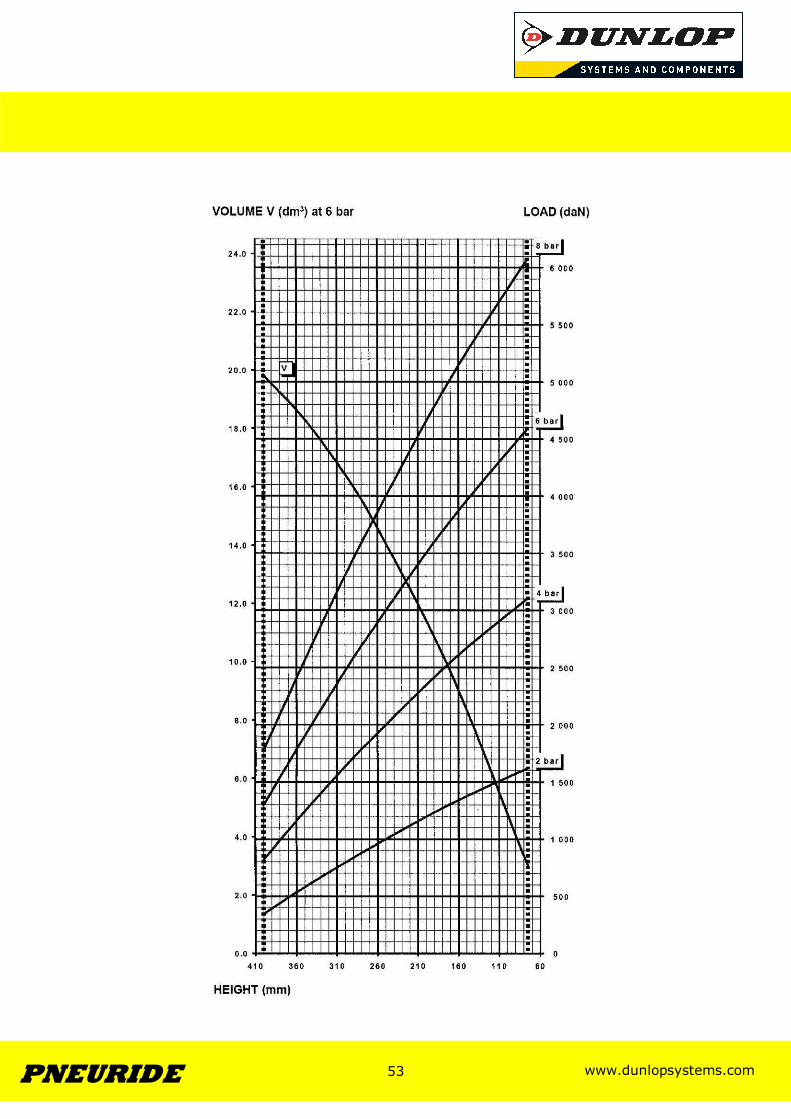
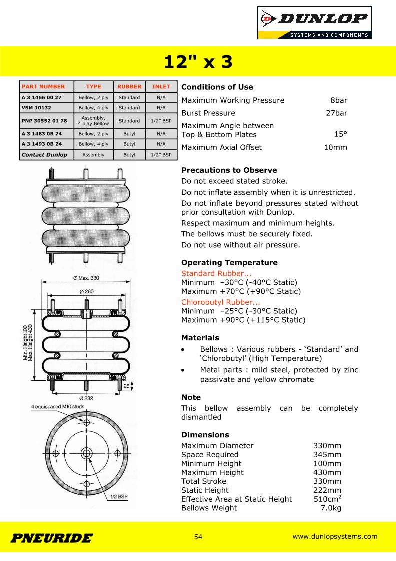
passivate and yellow chromate Note This bellow assembly can be completely dismantled Dimensions Maximum Diameter 330mm Space Required 345mm Minimum Height 100mm Maximum Height 430mm Total Stroke 330mm Static Height 222mm Effective Area at Static Height 510cm2
Bellows Weight 7.0kg
12" x 3
Maximum Working Pressure 8bar
Burst Pressure 27bar
Maximum Angle between Top & Bottom Plates
15°
Maximum Axial Offset 10mm
PART NUMBER TYPE RUBBER INLET
A 3 1466 00 27 Bellow, 2 ply Standard N/A
VSM 10132 Bellow, 4 ply Standard N/A
PNP 30552 01 78 Assembly, 4 play Bellow Standard 1/2” BSP
A 3 1483 0B 24 Bellow, 2 ply Butyl N/A
A 3 1493 0B 24 Bellow, 4 ply Butyl N/A
Contact Dunlop Assembly Butyl 1/2” BSP
www.dunlopsystems.com 55 PNEURIDE
55
www.dunlopsystems.com 56 PNEURIDE
56
Conditions of Use
Precautions to Observe Do not exceed stated stroke. Do not inflate assembly when it is unrestricted. Do not inflate beyond pressures stated without prior consultation with Dunlop. Respect maximum and minimum heights. The bellows must be securely fixed. Do not use without air pressure. Operating Temperature Standard Rubber... Minimum –30°C (-40°C Static) Maximum +70°C (+90°C Static) Chlorobutyl Rubber... Minimum –25°C (-30°C Static) Maximum +90°C (+115°C Static) Materials • Bellows : Various rubbers - ‘Standard’ and
‘Chlorobutyl’ (High Temperature) • Metal parts : mild steel, protected by zinc
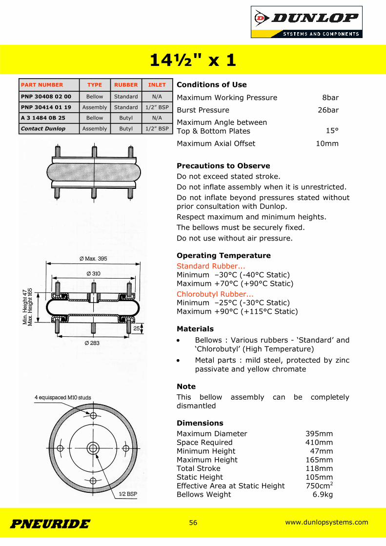
passivate and yellow chromate Note This bellow assembly can be completely dismantled Dimensions Maximum Diameter 395mm Space Required 410mm Minimum Height 47mm Maximum Height 165mm Total Stroke 118mm Static Height 105mm Effective Area at Static Height 750cm2
Bellows Weight 6.9kg
14½" x 1
Maximum Working Pressure 8bar
Burst Pressure 26bar
Maximum Angle between Top & Bottom Plates
15°
Maximum Axial Offset 10mm
PART NUMBER TYPE RUBBER INLET
PNP 30408 02 00 Bellow Standard N/A
PNP 30414 01 19 Assembly Standard 1/2” BSP
A 3 1484 0B 25 Bellow Butyl N/A
Contact Dunlop Assembly Butyl 1/2” BSP

www.dunlopsystems.com 57 PNEURIDE
57
www.dunlopsystems.com 58 PNEURIDE
58
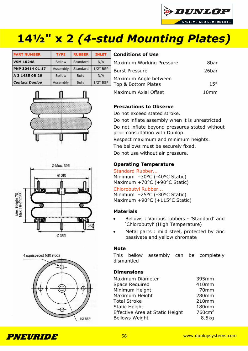
Conditions of Use
Precautions to Observe Do not exceed stated stroke. Do not inflate assembly when it is unrestricted. Do not inflate beyond pressures stated without prior consultation with Dunlop. Respect maximum and minimum heights. The bellows must be securely fixed. Do not use without air pressure. Operating Temperature Standard Rubber... Minimum –30°C (-40°C Static) Maximum +70°C (+90°C Static) Chlorobutyl Rubber... Minimum –25°C (-30°C Static) Maximum +90°C (+115°C Static) Materials • Bellows : Various rubbers - ‘Standard’ and
‘Chlorobutyl’ (High Temperature) • Metal parts : mild steel, protected by zinc
passivate and yellow chromate Note This bellow assembly can be completely dismantled Dimensions Maximum Diameter 395mm Space Required 410mm Minimum Height 70mm Maximum Height 280mm Total Stroke 210mm Static Height 180mm Effective Area at Static Height 760cm2
Bellows Weight 8.5kg
14½" x 2 (4-stud Mounting Plates)
Maximum Working Pressure 8bar
Burst Pressure 26bar
Maximum Angle between Top & Bottom Plates
15°
Maximum Axial Offset 10mm
PART NUMBER TYPE RUBBER INLET
VSM 10248 Bellow Standard N/A
PNP 30414 01 17 Assembly Standard 1/2” BSP
A 3 1485 0B 26 Bellow Butyl N/A
Contact Dunlop Assembly Butyl 1/2” BSP
www.dunlopsystems.com 59 PNEURIDE
59
www.dunlopsystems.com 60 PNEURIDE
60
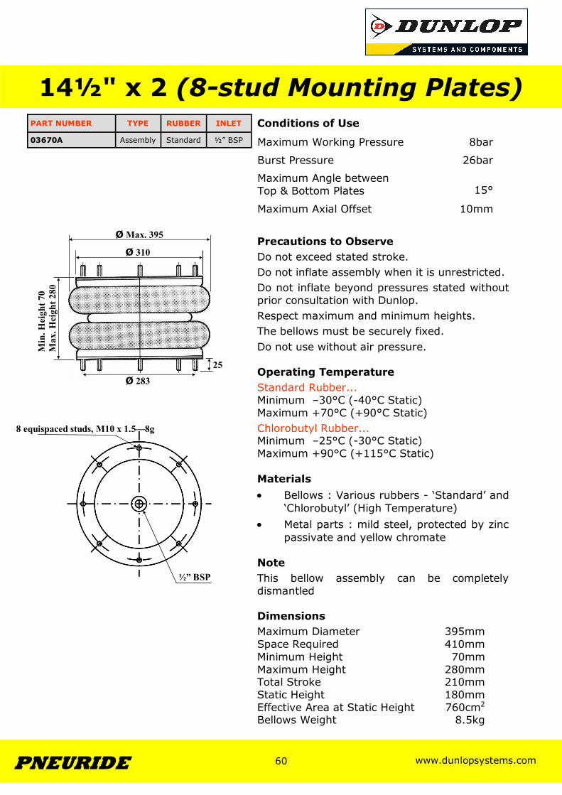
Conditions of Use
Precautions to Observe Do not exceed stated stroke. Do not inflate assembly when it is unrestricted. Do not inflate beyond pressures stated without prior consultation with Dunlop. Respect maximum and minimum heights. The bellows must be securely fixed. Do not use without air pressure. Operating Temperature Standard Rubber... Minimum –30°C (-40°C Static) Maximum +70°C (+90°C Static) Chlorobutyl Rubber... Minimum –25°C (-30°C Static) Maximum +90°C (+115°C Static) Materials • Bellows : Various rubbers - ‘Standard’ and
‘Chlorobutyl’ (High Temperature) • Metal parts : mild steel, protected by zinc
passivate and yellow chromate Note This bellow assembly can be completely dismantled Dimensions Maximum Diameter 395mm Space Required 410mm Minimum Height 70mm Maximum Height 280mm Total Stroke 210mm Static Height 180mm Effective Area at Static Height 760cm2
Bellows Weight 8.5kg
14½" x 2 (8-stud Mounting Plates)
Maximum Working Pressure 8bar
Burst Pressure 26bar
Maximum Angle between Top & Bottom Plates
15°
Maximum Axial Offset 10mm
PART NUMBER TYPE RUBBER INLET
03670A Assembly Standard ½” BSP
8 equispaced studs, M10 x 1.5—8g
Ø 283
25
Ø 310
Ø Max. 395
Min
. Hei
ght 7
0 M
ax. H
eigh
t 280
½” BSP

www.dunlopsystems.com 61 PNEURIDE
61
www.dunlopsystems.com 62 PNEURIDE
62
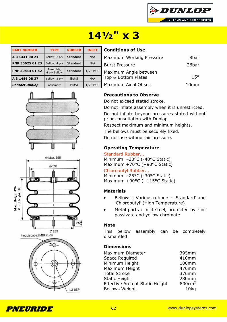
Conditions of Use
Precautions to Observe Do not exceed stated stroke. Do not inflate assembly when it is unrestricted. Do not inflate beyond pressures stated without prior consultation with Dunlop. Respect maximum and minimum heights. The bellows must be securely fixed. Do not use without air pressure. Operating Temperature Standard Rubber... Minimum –30°C (-40°C Static) Maximum +70°C (+90°C Static) Chlorobutyl Rubber... Minimum –25°C (-30°C Static) Maximum +90°C (+115°C Static) Materials • Bellows : Various rubbers - ‘Standard’ and
‘Chlorobutyl’ (High Temperature) • Metal parts : mild steel, protected by zinc
passivate and yellow chromate Note This bellow assembly can be completely dismantled Dimensions Maximum Diameter 395mm Space Required 410mm Minimum Height 100mm Maximum Height 476mm Total Stroke 376mm Static Height 280mm Effective Area at Static Height 800cm2
Bellows Weight 10kg
14½" x 3
Maximum Working Pressure 8bar
Burst Pressure 26bar
Maximum Angle between Top & Bottom Plates
15°
Maximum Axial Offset 10mm
PART NUMBER TYPE RUBBER INLET
A 3 1441 00 21 Bellow, 2 ply Standard N/A
PNP 30414 01 42 Assembly, 4 ply Bellow Standard 1/2” BSP
A 3 1486 0B 27 Bellow, 2 ply Butyl N/A
Contact Dunlop Assembly Butyl 1/2” BSP
PNP 30625 01 23 Bellow, 4 ply Standard N/A
Max
. Hei
ght 4
76
Min
. Hei
ght 1
00
www.dunlopsystems.com 63 PNEURIDE
63
www.dunlopsystems.com 64 PNEURIDE
64
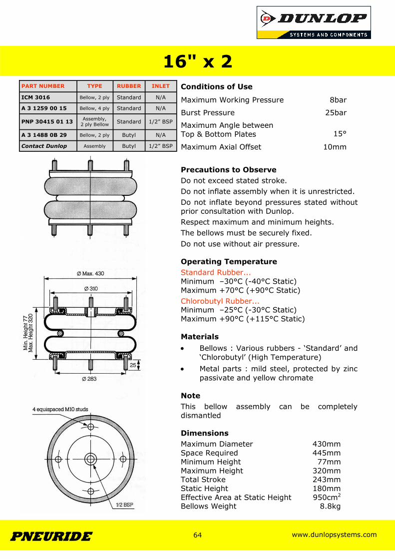
Conditions of Use
Precautions to Observe Do not exceed stated stroke. Do not inflate assembly when it is unrestricted. Do not inflate beyond pressures stated without prior consultation with Dunlop. Respect maximum and minimum heights. The bellows must be securely fixed. Do not use without air pressure. Operating Temperature Standard Rubber... Minimum –30°C (-40°C Static) Maximum +70°C (+90°C Static) Chlorobutyl Rubber... Minimum –25°C (-30°C Static) Maximum +90°C (+115°C Static) Materials • Bellows : Various rubbers - ‘Standard’ and
‘Chlorobutyl’ (High Temperature) • Metal parts : mild steel, protected by zinc
passivate and yellow chromate Note This bellow assembly can be completely dismantled Dimensions Maximum Diameter 430mm Space Required 445mm Minimum Height 77mm Maximum Height 320mm Total Stroke 243mm Static Height 180mm Effective Area at Static Height 950cm2
Bellows Weight 8.8kg
16" x 2
Maximum Working Pressure 8bar
Burst Pressure 25bar
Maximum Angle between Top & Bottom Plates
15°
Maximum Axial Offset 10mm
PART NUMBER TYPE RUBBER INLET
ICM 3016 Bellow, 2 ply Standard N/A
A 3 1259 00 15 Bellow, 4 ply Standard N/A
PNP 30415 01 13 Assembly, 2 ply Bellow Standard 1/2” BSP
A 3 1488 0B 29 Bellow, 2 ply Butyl N/A
Contact Dunlop Assembly Butyl 1/2” BSP
www.dunlopsystems.com 65 PNEURIDE
65
www.dunlopsystems.com 66 PNEURIDE
66
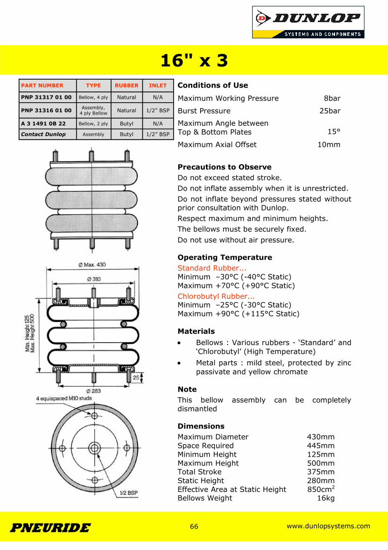
Conditions of Use
Precautions to Observe Do not exceed stated stroke. Do not inflate assembly when it is unrestricted. Do not inflate beyond pressures stated without prior consultation with Dunlop. Respect maximum and minimum heights. The bellows must be securely fixed. Do not use without air pressure. Operating Temperature Standard Rubber... Minimum –30°C (-40°C Static) Maximum +70°C (+90°C Static) Chlorobutyl Rubber... Minimum –25°C (-30°C Static) Maximum +90°C (+115°C Static) Materials • Bellows : Various rubbers - ‘Standard’ and
‘Chlorobutyl’ (High Temperature) • Metal parts : mild steel, protected by zinc
passivate and yellow chromate Note This bellow assembly can be completely dismantled Dimensions Maximum Diameter 430mm Space Required 445mm Minimum Height 125mm Maximum Height 500mm Total Stroke 375mm Static Height 280mm Effective Area at Static Height 850cm2
Bellows Weight 16kg
16" x 3
Maximum Working Pressure 8bar
Burst Pressure 25bar
Maximum Angle between Top & Bottom Plates
15°
Maximum Axial Offset 10mm
PART NUMBER TYPE RUBBER INLET
PNP 31317 01 00 Bellow, 4 ply Natural N/A
PNP 31316 01 00 Assembly, 4 ply Bellow Natural 1/2” BSP
A 3 1491 0B 22 Bellow, 2 ply Butyl N/A
Contact Dunlop Assembly Butyl 1/2” BSP
www.dunlopsystems.com 67 PNEURIDE
67
www.dunlopsystems.com 68 PNEURIDE
68
Section 3
Large Bellow
www.dunlopsystems.com 69 PNEURIDE
69
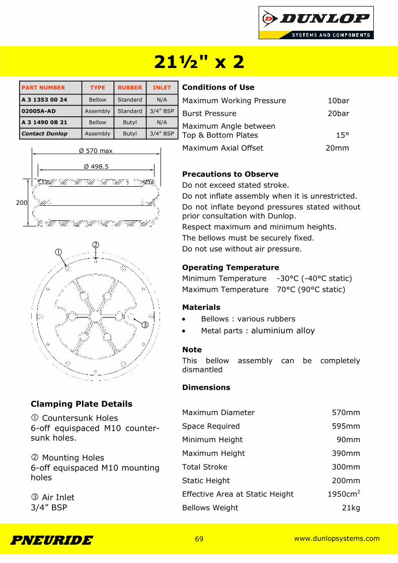
21½" x 2 PART NUMBER TYPE RUBBER INLET
02005A-AD Assembly Standard 3/4” BSP
A 3 1353 00 24 Bellow Standard N/A
A 3 1490 0B 21 Bellow Butyl N/A
Contact Dunlop Assembly Butyl 3/4” BSP
Conditions of Use
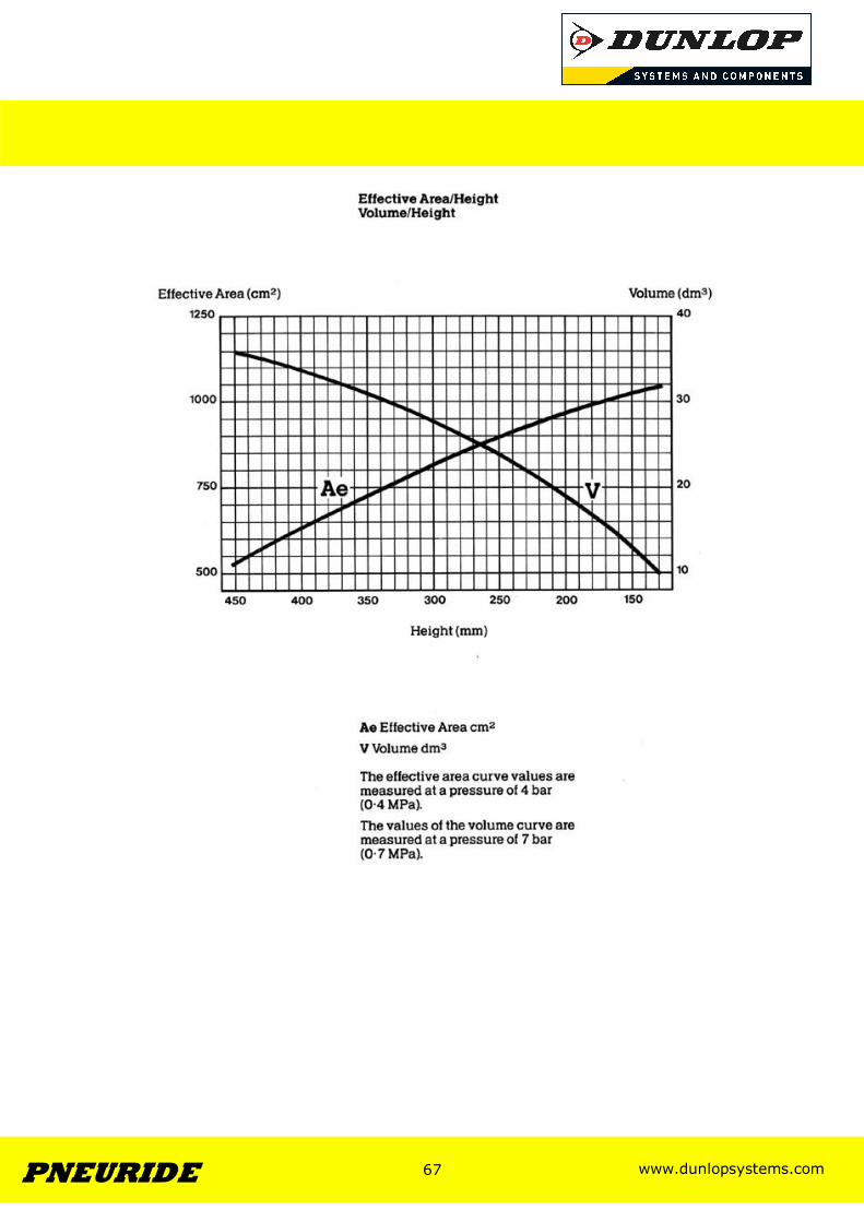
Precautions to Observe Do not exceed stated stroke. Do not inflate assembly when it is unrestricted. Do not inflate beyond pressures stated without prior consultation with Dunlop. Respect maximum and minimum heights. The bellows must be securely fixed. Do not use without air pressure. Operating Temperature Minimum Temperature -30°C (-40°C static) Maximum Temperature 70°C (90°C static) Materials • Bellows : various rubbers • Metal parts : aluminium alloy Note This bellow assembly can be completely dismantled Dimensions
Maximum Working Pressure 10bar
Burst Pressure 20bar
Maximum Angle between Top & Bottom Plates
15°
Maximum Axial Offset 20mm
Maximum Diameter 570mm
Space Required 595mm
Minimum Height 90mm
Maximum Height 390mm
Total Stroke 300mm
Static Height 200mm
Effective Area at Static Height 1950cm2
Bellows Weight 21kg
Ø 570 max
Ø 498.5
200
� �
�
Clamping Plate Details
� Countersunk Holes 6-off equispaced M10 counter- sunk holes. � Mounting Holes 6-off equispaced M10 mounting holes � Air Inlet 3/4” BSP
www.dunlopsystems.com 70 PNEURIDE
70
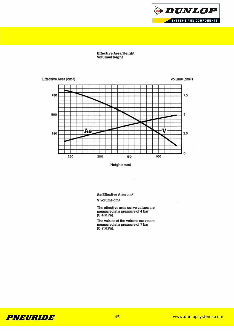
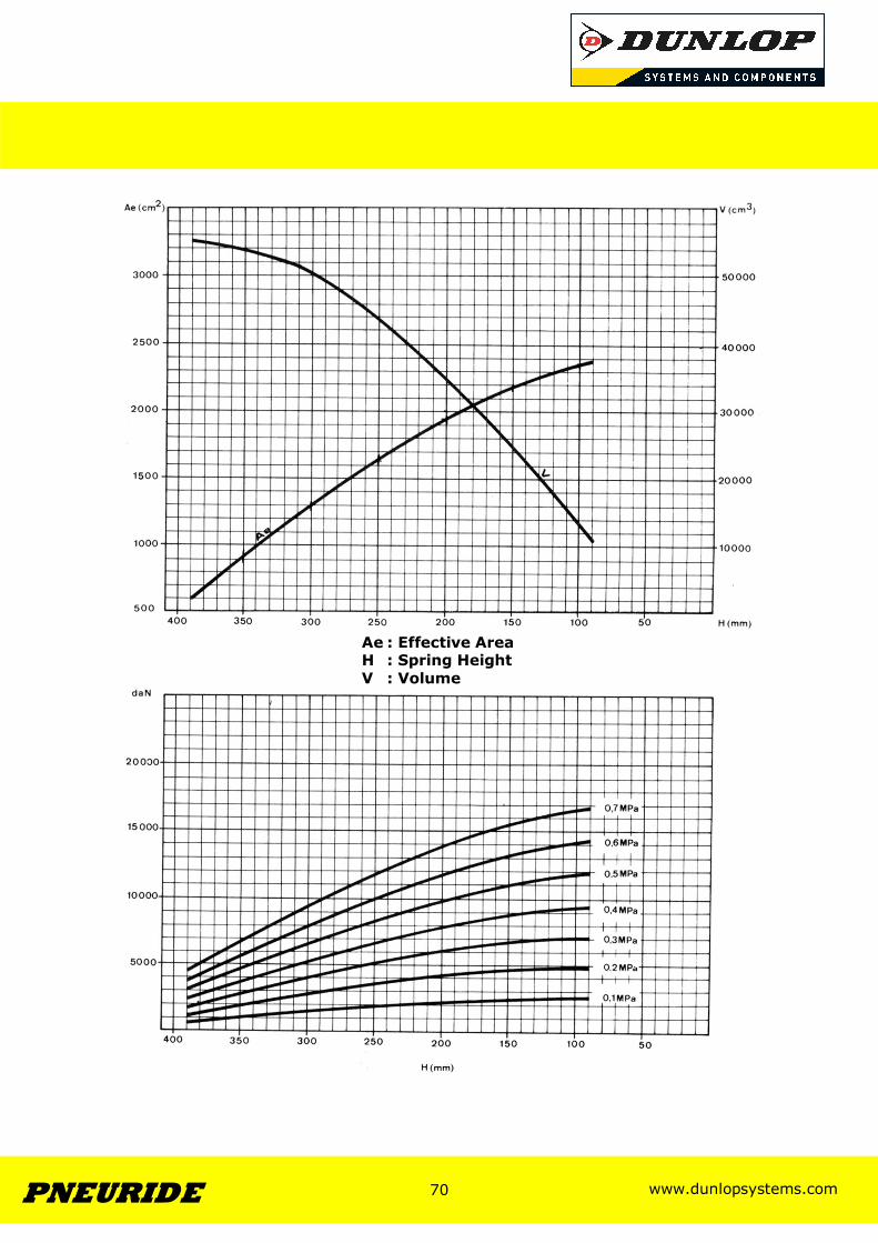
Ae : Effective Area H : Spring Height V : Volume

Dunlop Systems and Components Central Boulevard, Prologis Park, Coventry CV6 4QJ England Tel: +44 (0)24 7688 9900 Fax: +44 (0)24 7688 9901 E-mail: [email protected] www.dunlopsystems.com
Related Documents