INTERACTIVE SCHEMATIC The Bookmarks panel will allow you to quickly navigate to points of interest. Click on any text that is BLUE and underlined. These are hyperlinks that can be used to navi- gate the schematic and machine views. When only one callout is showing on a machine view this button will make all of the callouts visible. This button is located in the top right corner of every machine view page. VIEW ALL CALLOUTS Cover Page Information Schematic Machine Views Component Table Tap Table Fluid Power Symbols Electrical Symbols Front Frame Rear Frame Tap Views Features Options Bookmarks X EC-C3 EC-C2 E-C60 EC-C1 E-C61 To set your screen resolution do the following: RIGHT CLICK on the DESKTOP. Select PROPERTIES. CLICK the SETTINGS TAB. MOVE THE SLIDER under SCREEN RESOLUTION until it shows 1024 X 768. CLICK OK to apply the resolution. This document is best viewed at a screen resolution of 1024 X 768. FUNCTION Zoom In HOTKEYS (Keyboard Shortcuts) Zoom Out Fit to Page Hand Tool “CTRL” / “+” KEYS “CTRL” / “-” “CTRL” / “0” (zero) “SPACEBAR” (hold down) Find “CTRL” / “F”

Welcome message from author
This document is posted to help you gain knowledge. Please leave a comment to let me know what you think about it! Share it to your friends and learn new things together.
Transcript
INTERACTIVE SCHEMATIC
The Bookmarks panel will allow you to quickly navigate to points of interest.
Click on any text that is BLUE and underlined. These are hyperlinks that can be used to navi-gate the schematic and machine views.
When only one callout is showing on a machine view this button will make all of the callouts visible. This button is located in the top right corner of every machine view page.
VIEW ALL CALLOUTS
Cover PageInformation
SchematicMachine Views
Component TableTap Table
Fluid Power Symbols
Electrical Symbols
Front Frame
Rear Frame
Tap Views
Features
Options
Bookmarks X
EC-C3EC-C2 E-C60
EC-C1
E-C61
To set your screen resolution do the following:RIGHT CLICK on the DESKTOP. Select PROPERTIES. CLICK the SETTINGS TAB. MOVE THE SLIDER under SCREEN RESOLUTION until it shows 1024 X 768. CLICK OK to apply the resolution.
This document is best viewed at a screen resolution of 1024 X 768.
FUNCTION Zoom In
HOTKEYS (Keyboard Shortcuts)
Zoom OutFit to PageHand Tool
“CTRL” / “+”
KEYS
“CTRL” / “-”“CTRL” / “0” (zero)“SPACEBAR” (hold down)
Find “CTRL” / “F”
RENR8034-03April 2009
Hoist, Steering, Suspension, and Fan Drive
725 and 730 Articulated TruckHydraulic System725:WWA1-UPB1L1-UPAFX1179-1648
730:WWB1-UPAGF1092-1561B1M1-UP
Printed in U.S.A.© 2009 Caterpillar, All Rights Reserved

Page 1 of 2COMPONENT LOCATION
Description MachineLocation
SchematicLocation
AGF / AFX B1L / B1MAccumulator Gp - Brake 236-7794 236-7794 2 E-8Accumulator Gp - Park Brake 163-5632 163-5632 1 F-7Body - Drain Valve 8J-8782 8J-8782 6 A-5Brake Gp - Parking 160-8009 160-8009 3 F-8Brake Gp - Service 159-7596 159-7596 4 B-1, C-1, C-9, D-9Breather Gp - Hydraulic Tank 160-5615 160-5615 6 A-5Cylinder Gp - Suspension 200-4300 200-4300 10 A-3, F-3
Cylinder Gp - Hoist: 725 730
241-4071241-4062
285-4031285-4032 7 D-1, F-1
Cylinder Gp - Steering: Left Right
215-3024215-3023
273-3267273-3266 8 D-2
Filter Element As. - Oil 132-8876 132-8876 6 A-4Fitting As - Male 164-5567 164-5567 9 E-1Manifold - Hoist 156-4504 156-4504 9 E-2Manifold - Press. Switch 230-3008 230-3008 11 E-9Manifold - Service Brake 7U-9277 7U-9277 12 B-1, C-1, C-9Motor - Fan Drive 240-6746 240-6746 14 F-9Pump and Motor Gp - Sec. Str 173-8787 253-8095 1 C-4Pump Gp - Fan, Brake, Hoist 240-2647 240-2647 15 C-7Pump Gp - Steering, Hoist 240-2647 240-2647 16 C-5Pump Group - Metering 223-7718 223-7718 17 D-3Screen - Main Control Valve 6E-5066 6E-5066 18 E-6, F-7Screen - Hydr. Tank Supply 119-4885 119-4885 6 A-5Screen As. - Hydr. Tank Fill 6J-3795 6J-3795 6 A-4Switch As - Diff. Press. Hydr. 117-7773 117-7773 6 A-4Switch As - Parking Press. 172-7073 213-6947 18 F-7Switch As - Press., Stop Light 172-7071 172-7071 11 E-9Switch As - Press., Xmsn 172-7071 172-7071 11 E-9Switch As. - Low Brake Press. 3E-7688 266-6477 18 F-7
PartNumber
Switch As. - Press.,Steering Oil 3E-6450 3E-6450 18 D-6Tank Gp - Hydraulic 234-5600 234-5600 6 A-4Valve - Fluid Sampling 8C-3446 8C-3446 22 B-4

Page 2 of 2COMPONENT LOCATION
Description MachineLocation
SchematicLocation
AGF / AFX B1L / B1MValve Gp - Main Control 240-0678 240-0678 18 F-5Valve Gp - Brake Control 224-3207 224-3207 20 D-9Valve Gp - Check 1 128-2780 128-2780 18 D-5
Valve Gp - Check 3 158-9956 158-9956 18 F-6Valve Gp - Check 4 194-1723 194-1723 18 D-5Valve Gp - Check 5 239-0617 239-0617 18 D-5
Valve Gp - Check 7 252-6485 252-6485 18 E-6Valve Gp - Check 145-8983 145-8983 6 B-4Valve Gp - Check Hydr. Tank 239-1132 Not Used 6 B-4Valve Gp - Control Valve 241-4680 281-3307 19 F-3Valve Gp - Diverter 1 239-0594 239-0594 18 D-6Valve Gp - Diverter 2 239-0603 239-0603 18 E-6Valve Gp - Diverter 3 239-0605 239-0605 18 D-6Valve Gp - Diverter 4 239-0621 239-0621 18 F-6Valve Gp - Pressure Reducing 239-0615 239-0615 18 E-6Valve Gp - Relief 1 241-6256 241-6256 18 F-3Valve Gp - Relief 2 239-0612 239-0612 18 F-6Valve Gp - Relief 3 239-0614 239-0614 18 F-5Valve Gp - Relief, Steer Cyl. 214-9055 268-5823 21 D-2, E-2
Valve Gp - Shuttle 3 239-0618 239-0618 18 E-6Valve Gp - Shuttle 4 257-8414 257-8414 18 F-6Valve Gp - Solenoid 235-4605 257-0267 23 E-3, F-3Valve Gp - Solenoid 1 191-7785 191-7785 18 E-6Valve Gp - Solenoid 2 201-0950 201-0950 18 F-7
PartNumber
Valve Gp - Check 2 128-2780 128-2780 18 E-6
Valve Gp - Check 6 239-0617 239-0617 18 D-6
Valve Gp - Shuttle 2 239-0618 239-0618 18 D-6Valve Gp - Shuttle 1 239-0618 239-0618 18 D-5

TAP LOCATION
TapNumber Description Schematic
LocationAA Hoist Raise & Lower Pressure E-5BB Steer Pressure D-5CC Hoist Pilot Pressure E-5DD Front Brake Pressure D-9EE Steer & Hoist Pump Pressure C-6FF Fan Drive Pressure E-7GG Brake Accumulator Charge Pressure E-7HH Park Brake Pressure F-7JJ Otg. Lube & Diff. Lock Pressure Not Shown KK Fan, Brake, & Hoist Pump Pressure D-6NN Rear Brake Pressure C-2PP Scheduled Oil Sampling B-4RR Body Over Center-Service Point E-1TT Pump Case Fill B-6, B-5

FLUID POWER SYMBOLS
ONE POSITION TWO POSITION THREE POSITION
VENTED PRESSURIZED RETURN ABOVE FLUID LEVEL RETURN BELOW FLUID LEVEL
LINES CROSSING LINES JOINING
TWO-WAY THREE-WAY FOUR-WAY
SPRING CONTROL VALVES RESTRICTION LINE RESTRICTION(FIXED)
2-SECTION PUMP
MAIN AUX.
SPRING(ADJUSTABLE)
VARIABILITY LINE RESTRICTION(VARIABLE)
LINE RESTRICTIONVARIABLE and PRESSURE
COMPENSATED
PRESSURECOMPENSATION
PUMP: VARIABLE andPRESSURE COMPENSATED
ENERGY TRIANGLESHYDRAULIC PNEUMATIC
MEASUREMENT
PRESSURE TEMPERATURE FLOW
ROTATING SHAFTS
UNIDIRECTIONAL BIDIRECTIONAL
PUSH-PULL LEVER PEDALGENERAL MANUAL PUSH BUTTON SPRING
MANUAL CONTROL SYMBOLS
HYDRAULIC MOTORS
FIXEDDISPLACEMENT
VARIABLE DISPLACEMENTNON-COMPENSATED
UNIDIRECTIONAL
BIDIRECTIONAL
HYDRAULIC PUMPS
FLUID STORAGE RESERVOIRS
CROSSING AND JOINING LINES
VALVE ENVELOPES VALVE PORTS
BASIC COMPONENT SYMBOLS
FLUID CONDITIONERPUMP or MOTOR
FIXEDDISPLACEMENT
VARIABLE DISPLACEMENTNON-COMPENSATED
UNIDIRECTIONAL
BIDIRECTIONAL
VALVES
PILOT CONTROL SYMBOLSRELEASED PRESSURE
EXTERNAL RETURN INTERNAL RETURN
REMOTE SUPPLY PRESSURE
SIMPLIFIED COMPLETE INTERNALSUPPLY PRESSURE
ACCUMULATORS
SPRING LOADED GAS CHARGED
SOLENOIDor MANUAL
SOLENOIDand PILOT
SOLENOID and PILOT or MANUAL
COMBINATION CONTROLS
SOLENOID SERVO THERMAL DETENT
HYDRAULIC AND PNEUMATIC CYLINDERS
DOUBLE ACTINGSINGLE ACTING
BASICSYMBOL
SPRINGLOADED
CHECK VALVES
TWOPOSITION
INFINITEPOSITIONING
FLOW IN ONEDIRECTION
FLOW ALLOWED INEITHER DIRECTION
THREEPOSITION
CROSSFLOW
PARALLELFLOW
INTERNAL PASSAGEWAYS
NORMAL POSITION
A B
P T
A B
P TSHIFTED POSITION INFINITE POSITION
CONTROL VALVES
ATTACHMENT
MANUAL SHUTOFF
SHUTTLE PILOTCONTROLLED

ELECTRICAL SYMBOLSHydraulic Symbols (Electrical)
325-AG135 PK-14
Circuit IdentificationNumber
Wire Color Wire Gauge
Harness identification codeThis example indicateswire 135 in harness "AG".
325-PK-14
Wire Gauge
Wire Color
Circuit Number Identification
Wire Number Identification Codes
Current Standard
Previous Standard
Electrical Schematic Example Hydraulic Schematic Example
325-PK
Wire ColorCircuit Number Identification
B A
Wire
Wire
(EXAMPLE VALVE)
Current Standard
Transducer(Fluid)
Transducer(Gas / Air)
G
Generator
Electrical WirePressure Switch
MElectric Motor
Pressure Switch (Adjustable)
Temperature Switch
PressureSymbol
TemperatureSymbol
LevelSymbol
FlowSymbol
Electrical Symbols (Electrical)
T
LINE PATTERNS
Drain / Return Lines
Component Group
Pilot / Load Sensing Pressure
Pressure Line
Attachment
Air Line
CALLOUTS
Taps (Pressure, Sampling,Sensor) by letterYY
HYDRAULIC CIRCUIT COLOR DESCRIPTIONSPump Output (Steering and Hoist)
Supply LineDrain / Return LineBrake CircuitSteering Circuit
Pump Output (Secondary Steering)
Hoist Circuit
Pump Output (Fan, Brake, and Hoist)
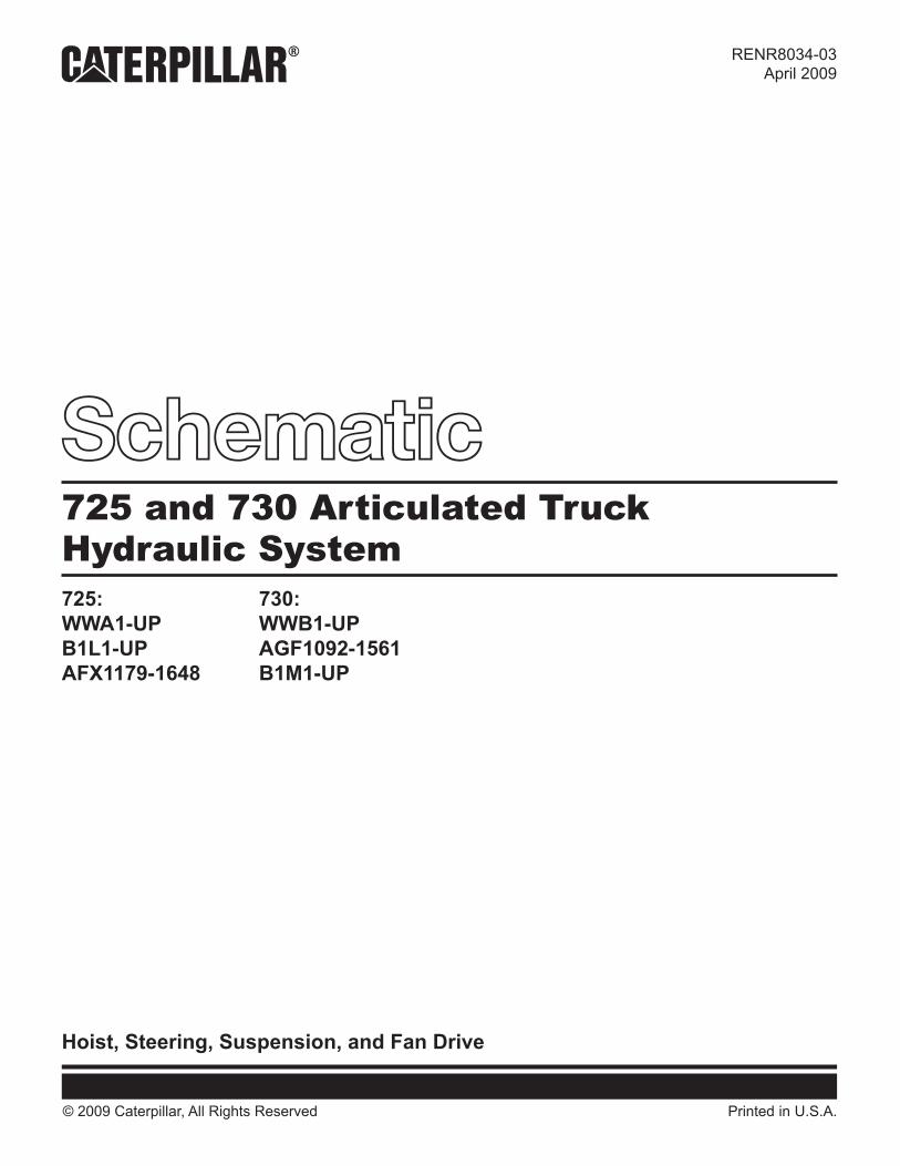
THIS SCHEMATIC IS FOR THE 725 AND 730 ARTICULATED TRUCKHOIST, STEERING, SUSPENSION, AND FAN DRIVE HYDRAULIC SYSTEMSMEDIA #: RENR8034-03PART #: 235-2174 CHG 05PART #: 266-6458 CHG 03 Components are shown installed on a fully operable machine with the key and engine off and transmission shifter in neutral.Refer to the appropriate Service Manual for Troubleshooting, Specifications and Systems Operations
9 8 7 6 5 4 3 2 1
123456789
A
B
C
D
E
F F
E
D
C
B
A
B1
B2
P1
T1
P2
T2
FRONT AXLEBRAKE CALIPERS 725 TYPICAL
CENTER AXLEBRAKE CALIPERS
730TYPICAL
TRAILER
REMOTE PANELTEST POINT
REMOTE PANELTEST POINT
LS1 P3
ST
J
P
P1
M
B
S
X
RIGHTTURN
RAISE
R
L
P
T
LS
SW1
SW2
TRACTOR TRAILERHITCH CENTER LINE
HITCH CENTER LINETRACTOR TRAILER
LOWER B
RAISE A
REMOTE PANELTEST POINT
REMOTE PANELTEST POINT
REMOTE PANELTEST POINT
TPBR
TPH
F
LS2 P2 LS3P3TPD TPG SW3
LSST
TPA
T1
RBFBPB
TPJ
LS
TPST
P1
T2
ACC
TPM
RMT PANELTEST POINT
REMOTE PANELTEST POINT
NN
PP
(4) BRAKE GPSERVICE159-7596
TTTT
RR
AA
BB
CC
EE
KK
FF
REMOTE PANELTEST POINT GG
DD
HHREMOTE PANELTEST POINT
L L1
B
S
X
L L1
(11) MANIFOLDPRESSURE SWITCH230-3008
(20) VALVEBRAKE CONTROL
224-3207
(3) BRAKE GPPARKING160-8009
(14) MOTORFAN DRIVE
240-6746
(11) SWITCH ASPRESSURESTOP LIGHT172-7071
(11) SWITCH ASPRESSURE
TRANSMISSION SIGNAL172-7071
(2) ACCUMULATORBRAKE
236-7794
(4) BRAKE GPSERVICE159-7596
(4) BRAKE GPSERVICE159-7596
(18) VALVE GPMAIN CONTROL240-0678
(18) VALVE GPSOLENOID 2
201-0950
(18) VALVE GROUPSHUTTLE 4257-8414
(18) VALVE GPDIVERTER 4
239-0621
(18) VALVE GPRELIEF 2239-0612
(18) VALVE GPRELIEF 3239-0614
(18) SCREEN6E-5066
(18) SWITCH ASPARKING BRAKE
AFX/AGF: 172-7073B1L/B1M: 213-6947
(18) SWITCH ASLOW BRAKEPRESSURE
AFX/AGF: 3E-7688B1L/B1M: 266-6477
(1) ACCUMULATOR GPPARKING BRAKE
163-5632
(18) VALVE GPCHECK 3158-9956
(18) VALVE GPCHECK 2252-6485
(18) VALVE GPSOLENOID 1191-7785
(18) VALVE GPCHECK 7128-2780
(18) VALVE GPCHECK 1128-2780
(18) VALVE GPCHECK 4194-1723
(18) VALVE GPDIVERTER 2239-0603
(18) VALVE GPDIVERTER 3
239-0605
(18) VALVE GPPRESSURE RED
239-0615
(18) VALVE GPSHUTTLE 1239-0618
(18) VALVE GPSHUTTLE 2
239-0618
(18) VALVE GPSHUTTLE 3
239-0618
(18) VALVE GPCHECK 5239-0617
(18) SCREEN6E-5066
(18) VALVE GPCHECK
239-0617
(18) VALVE GPDIVERTER 1
239-0594
(15) PUMP GPFAN
BRAKEHOIST
240-2647
(16) PUMP GROUPSTEERING
HOIST240-2647
(1) PUMP AND MOTOR GPSECONDARY STEERING
AGF / AFX: 173-8787B1L / B1M: 253-8095
(18) SWITCH ASPRESSURE
STEERING OIL3E-6450
(19) VALVE GPCONTROL VALVE
AGF / AFX:241-4680
B1L / B1M:281-3307 (18) VALVE GP
RELIEF 1241-6256
(7) CYLINDER GPHOIST725: AGF / AFX 241-4071725: B1L / B1M 85-4031730: AGF / AFX 241-4062730: B1L / B1M 285-4032
(9) FITTING ASMALE164-5567
(17) PUMP GPMETERING223-7718
(8) CYLINDER GPLEFT-HAND STEERAGF / AFX: 215-3024B1L / B1M: 273-3267
(21) VALVE GPRELIEFSTEERING CYLINDERAGF / AFX: 214-9055B1L / B1M: 268-5823
(21) VALVE GPRELIEFSTEERING CYLINDERAGF / AFX: 214-9055B1L / B1M: 268-5823
CYLINDER GPRIGHT-HAND STEERAGF / AFX: 215-3023B1L / B1M: 273-3266
(23) VALVE GPSOLENOID LOWERAGF / AFX:235-4605B1L / B1M:257-0267
(23) VALVE GPSOLENOIDRAISEAGF / AFX:235-4605B1L / B1M:257-0267
(9) MANIFOLDHOIST
156-4504
(7) CYLINDER GPHOIST725: AGF / AFX 241-4071725: B1L / B1M 85-4031730: AGF / AFX 241-4062730: B1L / B1M 285-4032
(6) TANK GPHYDRAULIC234-5600
(6) FILTER ELEMENT AS.OIL132-8876
(6) SCREEN119-4885
(6) SCREEN AS.TANK FILL6J-3795
(6) BREATHER GP160-5615
(6) BODYDRAIN VALVE
8J-8782
(22) VALVEFLUID SAMPLING
8C-3446
(6) VALVE GPCHECK HYD TANKAGF / AFX: 239-1132B1L / B1M: NOT USED
(6) SWITCH AS.DIFF. PRESS.117-7773
(10) CYLINDER GPSUSPENSION
200-4300
(6) VALVE GPCHECK
145-8983
MANIFOLDSERVICE BRAKE7U-9277
(12) MANIFOLDSERVICE BRAKE
7U-9277
(4) BRAKE GPSERVICE159-7596
(10) CYLINDER GPSUSPENSION
200-4300
(12) MANIFOLDSERVICE BRAKE7U-9277
(12) MANIFOLDSERVICE BRAKE7U-9277
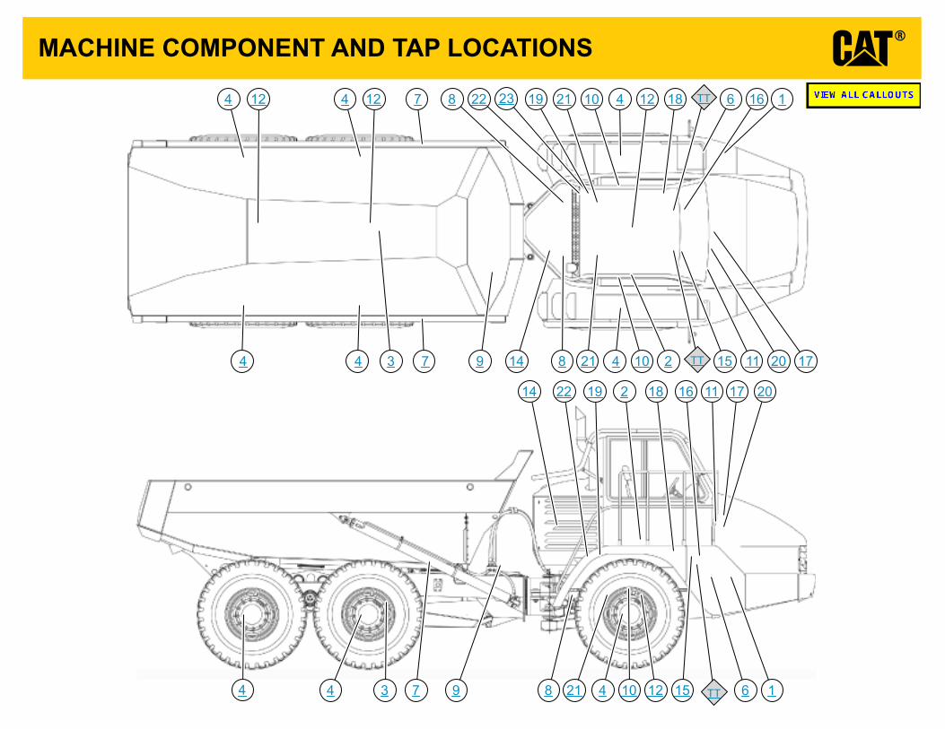
MACHINE COMPONENT AND TAP LOCATIONS
TT
TT
TT
2322
22
21
21
21
20
20
19
19
18
18
17
17
16
16
15
15
14
14
12
1212 12
11
11
10
10
10
9
9
8
8
8
7
7
7
6
6
4
4 4 4
44
4 4 4
3
3
2
2
1
1
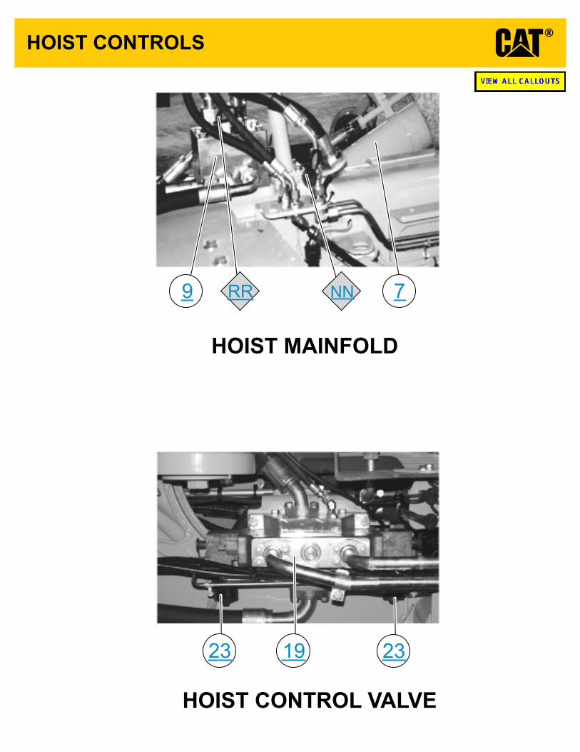
HOIST CONTROLS
HOIST CONTROL VALVE
HOIST MAINFOLD
RR NN
23 2319
9 7

HYDRAULIC TANK
DIFFERENTIAL PRESSURE SWITCH
6
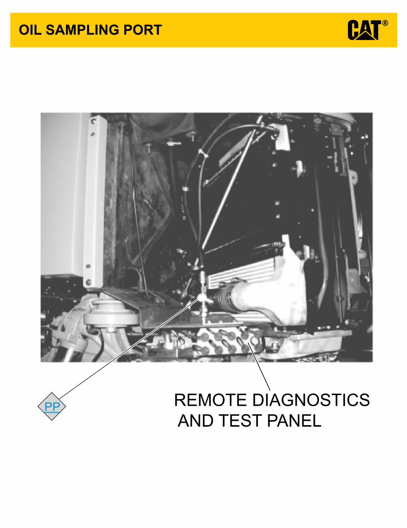
OIL SAMPLING PORT
REMOTE DIAGNOSTICS AND TEST PANEL
PP

REMOTE DIAGNOSTIC AND TEST PORT PANELLOCATIONS
KKJJHHGGFF
EEDDCCBBAA

SWITCH LOCATIONS
Main Control Valve
BRAKE MANIFOLD AND CONTROL VALVE
TRANSMISSION SIGNAL SWITCH
STOP LIGHT SWITCH
SECONDARY STEERING SWITCHSERVICE BRAKE SWITCH
PARKING BRAKE SWITCHPARKING BRAKE SOLENOID
FAN SOLENOID
20
18
11
Related Documents