DULCOMETER, Compact Controller Measured variable: Chlorine Assembly and operating instructions A1000 EN Part no.: 985626 Version: BA DM 208 08/15 EN Please carefully read these operating instructions before use. · Do not discard. The operator shall be liable for any damage caused by installation or operating errors. The latest version of the operating instructions are available on our homepage.

Welcome message from author
This document is posted to help you gain knowledge. Please leave a comment to let me know what you think about it! Share it to your friends and learn new things together.
Transcript
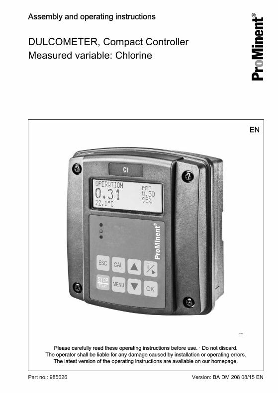
DULCOMETER, Compact ControllerMeasured variable: Chlorine
Assembly and operating instructions
A1000
EN
Part no.: 985626 Version: BA DM 208 08/15 EN
Please carefully read these operating instructions before use. · Do not discard.The operator shall be liable for any damage caused by installation or operating errors.
The latest version of the operating instructions are available on our homepage.
General non-discriminatory approach In order to make it easier to read, thisdocument uses the male form in grammat‐ical structures but with an implied neutralsense. It is aimed equally at both men andwomen. We kindly ask female readers fortheir understanding in this simplification ofthe text.
Supplementary information
Please read the supplementary information in its entirety.
Information
This provides important information relating to the correct operation of the unit oris intended to make your work easier.
Safety Information
The safety information includes detailed descriptions of the hazardous situation, seeÄ Chapter 2.1 ‘Explanation of the safety information’ on page 8The following symbols are used to highlight instructions, links, lists, results and other ele‐ments in this document:
Tab. 1: More symbolsSymbol Description
Action, step by step
⇨ Outcome of an action
Links to elements or sections of these instructions or other applicabledocuments
n List without set order
[Button] Display element (e.g. indicators)
Operating element (e.g. button, switch)
‘Display /GUI’ Screen elements (e.g. buttons, assignment of function keys)
CODE Presentation of software elements and/or texts
Supplemental directives
2
Table of contents1 Identity code........................................................................................................... 6
2 Introduction............................................................................................................. 82.1 Explanation of the safety information............................................................. 82.2 Users' qualifications...................................................................................... 10
3 Safety and responsibility....................................................................................... 123.1 General Safety Information.......................................................................... 123.2 Correct and proper use................................................................................ 14
4 Functional description........................................................................................... 154.1 Overview of the first level menu................................................................... 16
5 Assembly and installation..................................................................................... 195.1 Scope of delivery.......................................................................................... 205.2 Mounting (mechanical)................................................................................. 205.2.1 Wall mounting............................................................................................ 205.2.2 Pipe mounting........................................................................................... 225.2.3 Control panel mounting............................................................................. 235.3 Installation (electrical)................................................................................... 315.3.1 Cable Cross-Sections and Cable End Sleeves......................................... 325.3.2 Electrical connection of the chlorine sensor.............................................. 325.3.3 Terminal diagram / wiring.......................................................................... 335.3.4 Installation (electrical)................................................................................ 385.4 Switching of inductive loads......................................................................... 39
6 Commissioning..................................................................................................... 416.1 Initial commissioning.................................................................................... 416.2 Setting the controller during commissioning................................................. 41
7 Operating diagram................................................................................................ 427.1 Overview of equipment/Control elements.................................................... 427.2 Adjusting display contrast............................................................................. 437.3 Continuous display....................................................................................... 437.4 Info display................................................................................................... 447.5 Password...................................................................................................... 45
8 Operating menus ................................................................................................. 468.1 Calibrating (CAL) the chlorine sensor ......................................................... 468.1.1 Sensor slope calibration............................................................................ 48
Table of contents
3
8.1.2 Calibrate sensor zero point [CHECK ZERO]............................................. 518.1.3 Commissioning a new sensor................................................................... 528.2 Setting limit values [LIMITS] ........................................................................ 538.3 Setting the control [CONTROL] ................................................................... 558.4 Input setting (INPUT).................................................................................... 588.5 Output setting (OUTPUT)............................................................................. 618.6 DEVICE setting............................................................................................ 65
9 Control parameters and functions......................................................................... 669.1 DULCOMETER® Compact Controller function states ................................. 669.2 STOP/START key........................................................................................ 689.3 Priming (PRIME).......................................................................................... 699.4 Hysteresis limit............................................................................................. 709.5 Temperature correction variable.................................................................. 709.6 Checkout time for measured variable and correction variable..................... 729.7 Checkout time control................................................................................... 729.8 Power relay "P-REL" as limit value relay...................................................... 739.9 Setting and functional description of "Relay Used as a Solenoid Valve" .... 749.10 Alarm relay................................................................................................. 769.11 "Error logger" operating mode.................................................................... 76
10 Maintenance......................................................................................................... 7710.1 Changing the fuse, DULCOMETER® Compact Controller......................... 7710.2 Error messages.......................................................................................... 78
11 Technical data DULCOMETER® Compact Controller........................................... 8111.1 Permissible ambient conditions.................................................................. 8111.2 Sound Pressure Level................................................................................ 8111.3 Material data............................................................................................... 8211.4 Chemical Resistance.................................................................................. 8211.5 Dimensions and weights............................................................................ 83
12 Electrical data....................................................................................................... 84
13 Spare parts and accessories................................................................................ 87
14 Replacing spare part units ................................................................................... 8814.1 Replacing the top part of the housing......................................................... 8814.2 Replacing the lower part of the housing (wall/tube retaining bracket)........ 9014.3 Replacing the lower part of the housing (control panel installation)........... 92
Table of contents
4
15 Standards complied with and Declaration of Conformity...................................... 96
16 Disposal of Used Parts......................................................................................... 97
17 Index..................................................................................................................... 98
Table of contents
5
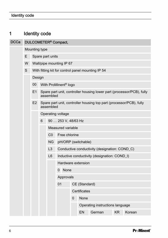
1 Identity codeDCCa DULCOMETER® Compact,
Mounting type
E Spare part units
W Wall/pipe mounting IP 67
S With fitting kit for control panel mounting IP 54
Design
00 With ProMinent® logo
E1 Spare part unit, controller housing lower part (processor/PCB), fullyassembled
E2 Spare part unit, controller housing top part (processor/PCB), fullyassembled
Operating voltage
6 90 … 253 V, 48/63 Hz
Measured variable
C0 Free chlorine
NG pH/ORP (switchable)
L3 Conductive conductivity (designation: COND_C)
L6 Inductive conductivity (designation: COND_I)
Hardware extension
0 None
Approvals
01 CE (Standard)
Certificates
0 None
Operating instructions language
EN German KR Korean
Identity code
6
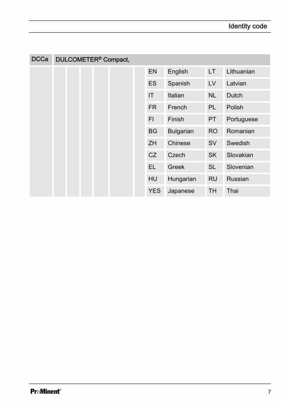
DCCa DULCOMETER® Compact,
EN English LT Lithuanian
ES Spanish LV Latvian
IT Italian NL Dutch
FR French PL Polish
FI Finish PT Portuguese
BG Bulgarian RO Romanian
ZH Chinese SV Swedish
CZ Czech SK Slovakian
EL Greek SL Slovenian
HU Hungarian RU Russian
YES Japanese TH Thai
Identity code
7
2 IntroductionData and functions
These operating instructions describe thetechnical data and functions of theDULCOMETER® Compact Controller,measured variable chlorine.
2.1 Explanation of the safetyinformation
Introduction
These operating instructions provide infor‐mation on the technical data and functionsof the product. These operating instruc‐tions provide detailed safety informationand are provided as clear step-by-stepinstructions.
The safety information and notes are cate‐gorised according to the followingscheme. A number of different symbolsare used to denote different situations.The symbols shown here serve only asexamples.
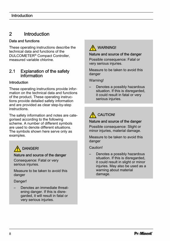
DANGER!
Nature and source of the dangerConsequence: Fatal or veryserious injuries.
Measure to be taken to avoid thisdanger
Danger!
– Denotes an immediate threat‐ening danger. If this is disre‐garded, it will result in fatal orvery serious injuries.
WARNING!
Nature and source of the dangerPossible consequence: Fatal orvery serious injuries.
Measure to be taken to avoid thisdanger
Warning!
– Denotes a possibly hazardoussituation. If this is disregarded,it could result in fatal or veryserious injuries.
CAUTION!
Nature and source of the dangerPossible consequence: Slight orminor injuries, material damage.
Measure to be taken to avoid thisdanger
Caution!
– Denotes a possibly hazardoussituation. If this is disregarded,it could result in slight or minorinjuries. May also be used as awarning about materialdamage.
Introduction
8
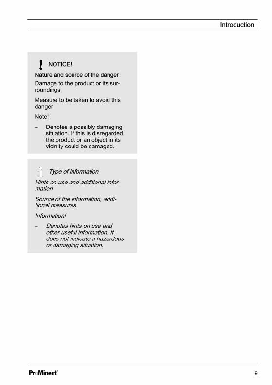
NOTICE!
Nature and source of the dangerDamage to the product or its sur‐roundings
Measure to be taken to avoid thisdanger
Note!
– Denotes a possibly damagingsituation. If this is disregarded,the product or an object in itsvicinity could be damaged.
Type of informationHints on use and additional infor‐mationSource of the information, addi‐tional measuresInformation!– Denotes hints on use and
other useful information. Itdoes not indicate a hazardousor damaging situation.
Introduction
9
2.2 Users' qualifications
WARNING!
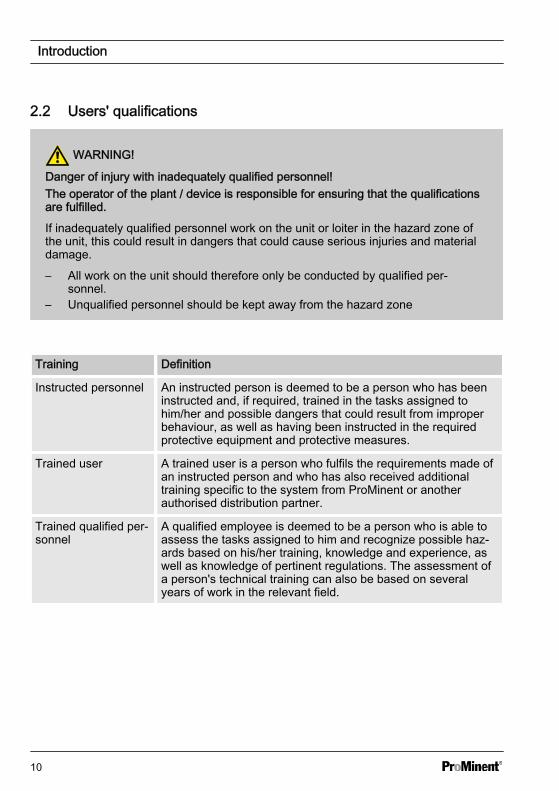
Danger of injury with inadequately qualified personnel!The operator of the plant / device is responsible for ensuring that the qualificationsare fulfilled.
If inadequately qualified personnel work on the unit or loiter in the hazard zone ofthe unit, this could result in dangers that could cause serious injuries and materialdamage.
– All work on the unit should therefore only be conducted by qualified per‐sonnel.
– Unqualified personnel should be kept away from the hazard zone
Training Definition
Instructed personnel An instructed person is deemed to be a person who has beeninstructed and, if required, trained in the tasks assigned tohim/her and possible dangers that could result from improperbehaviour, as well as having been instructed in the requiredprotective equipment and protective measures.
Trained user A trained user is a person who fulfils the requirements made ofan instructed person and who has also received additionaltraining specific to the system from ProMinent or anotherauthorised distribution partner.
Trained qualified per‐sonnel
A qualified employee is deemed to be a person who is able toassess the tasks assigned to him and recognize possible haz‐ards based on his/her training, knowledge and experience, aswell as knowledge of pertinent regulations. The assessment ofa person's technical training can also be based on severalyears of work in the relevant field.
Introduction
10
Training Definition
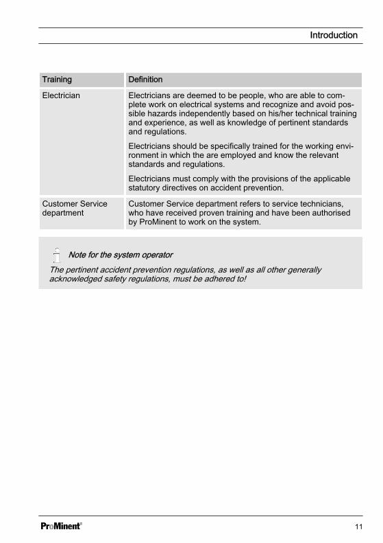
Electrician Electricians are deemed to be people, who are able to com‐plete work on electrical systems and recognize and avoid pos‐sible hazards independently based on his/her technical trainingand experience, as well as knowledge of pertinent standardsand regulations.
Electricians should be specifically trained for the working envi‐ronment in which the are employed and know the relevantstandards and regulations.
Electricians must comply with the provisions of the applicablestatutory directives on accident prevention.
Customer Servicedepartment
Customer Service department refers to service technicians,who have received proven training and have been authorisedby ProMinent to work on the system.
Note for the system operatorThe pertinent accident prevention regulations, as well as all other generallyacknowledged safety regulations, must be adhered to!
Introduction
11

3 Safety and responsibility3.1 General Safety Information
WARNING!
Live parts!Possible consequence: Fatal orvery serious injuries
– Measure: Disconnect themains power supply prior toopening the housing
– De-energise damaged, defec‐tive or manipulated units bydisconnecting the mains plug
WARNING!
Unauthorised access!Possible consequence: Fatal orvery serious injuries
– Measure: Ensure that therecan be no unauthorisedaccess to the unit
WARNING!
Operating errors!Possible consequence: Fatal orvery serious injuries
– The unit should only be oper‐ated by adequately qualifiedand technically expert per‐sonnel
– Please also observe the oper‐ating instructions for control‐lers and fittings and any othercomponent groups, such assensors, measuring waterpumps ...
– The operator is responsible forensuring that personnel arequalified
CAUTION!
Electronic malfunctionsPossible consequence: Materialdamage to destruction of the unit
– The mains connection cableand data cable should not belaid together with cables thatare prone to interference
– Measure: Take appropriateinterference suppressionmeasures
Safety and responsibility
12
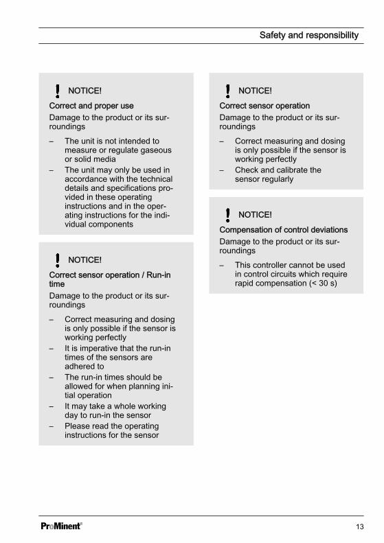
NOTICE!
Correct and proper useDamage to the product or its sur‐roundings
– The unit is not intended tomeasure or regulate gaseousor solid media
– The unit may only be used inaccordance with the technicaldetails and specifications pro‐vided in these operatinginstructions and in the oper‐ating instructions for the indi‐vidual components
NOTICE!
Correct sensor operation / Run-intimeDamage to the product or its sur‐roundings
– Correct measuring and dosingis only possible if the sensor isworking perfectly
– It is imperative that the run-intimes of the sensors areadhered to
– The run-in times should beallowed for when planning ini‐tial operation
– It may take a whole workingday to run-in the sensor
– Please read the operatinginstructions for the sensor
NOTICE!
Correct sensor operationDamage to the product or its sur‐roundings
– Correct measuring and dosingis only possible if the sensor isworking perfectly
– Check and calibrate thesensor regularly
NOTICE!
Compensation of control deviationsDamage to the product or its sur‐roundings
– This controller cannot be usedin control circuits which requirerapid compensation (< 30 s)
Safety and responsibility
13
3.2 Correct and proper use
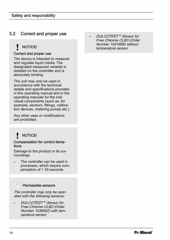
NOTICE!
Correct and proper useThe device is intended to measureand regulate liquid media. Thedesignated measured variable isdetailed on the controller and isabsolutely binding.
The unit may only be used inaccordance with the technicaldetails and specifications providedin this operating manual and in theoperating manuals for the indi‐vidual components (such as, forexample, sensors, fittings, calibra‐tion devices, metering pumps etc.).
Any other uses or modificationsare prohibited.
NOTICE!
Compensation for control devia‐tionsDamage to the product or its sur‐roundings
– The controller can be used inprocesses, which require com‐pensation of > 30 seconds
Permissible sensorsThe controller may only be oper‐ated with the following sensors:– DULCOTEST ® Sensor for
Free Chlorine CLB2 (OrderNumber 1038902) with tem‐perature sensor
– DULCOTEST ® Sensor forFree Chlorine CLB3 (OrderNumber 1041696) withouttemperature sensor
Safety and responsibility
14
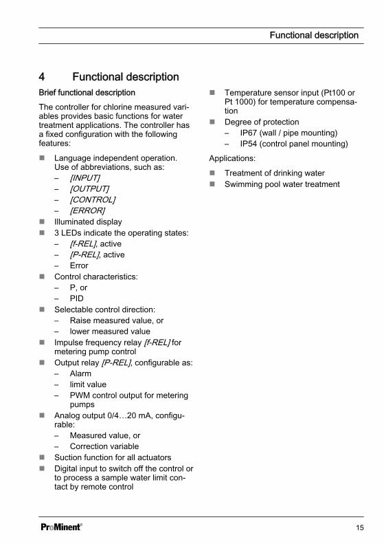
4 Functional descriptionBrief functional description
The controller for chlorine measured vari‐ables provides basic functions for watertreatment applications. The controller hasa fixed configuration with the followingfeatures:
n Language independent operation.Use of abbreviations, such as:– [INPUT]– [OUTPUT]– [CONTROL]– [ERROR]
n Illuminated displayn 3 LEDs indicate the operating states:
– [f-REL], active– [P-REL], active– Error
n Control characteristics:– P, or– PID
n Selectable control direction:– Raise measured value, or– lower measured value
n Impulse frequency relay [f-REL] formetering pump control
n Output relay [P-REL], configurable as:– Alarm– limit value– PWM control output for metering
pumpsn Analog output 0/4…20 mA, configu‐
rable:– Measured value, or– Correction variable
n Suction function for all actuatorsn Digital input to switch off the control or
to process a sample water limit con‐tact by remote control
n Temperature sensor input (Pt100 orPt 1000) for temperature compensa‐tion
n Degree of protection– IP67 (wall / pipe mounting)– IP54 (control panel mounting)
Applications:
n Treatment of drinking watern Swimming pool water treatment
Functional description
15
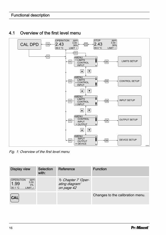
4.1 Overview of the first level menu
A0998
Fig. 1: Overview of the first level menu
Display view Selectionwith:
Reference Function
OPERATION ppm
1.9930.1 °C
3.000%
LIMIT ↓A1001
Ä Chapter 7 ‘Oper‐ating diagram’on page 42
Changes to the calibration menu.
Functional description
16
Display view Selectionwith:
Reference Function
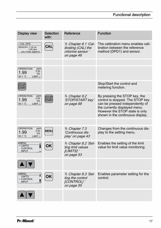
CAL DPD
4.95 ppmCAL=TAKE SAMPLE
SENSOR= 11.82 µA
A1002
Ä Chapter 8.1 ‘Cal‐ibrating (CAL) thechlorine sensor ’on page 46
The calibration menu enables cali‐bration between the referencemethod (DPD1) and sensor.
OPERATION ppm
1.9930.1 °C
3.000%
LIMIT ↓A1001
Stop/Start the control andmetering function.
OPERATION ppm
1.9930.1 °C
3.000%
LIMIT ↓A1001
Ä Chapter 9.2‘STOP/START key’on page 68
By pressing the STOP key, thecontrol is stopped. The STOP keycan be pressed independently ofthe currently displayed menu.However the STOP state is onlyshown in the continuous display.
OPERATION ppm
1.9930.1 °C
3.000%
LIMIT ↓A1001
Ä Chapter 7.3‘Continuous dis‐play’ on page 43
Changes from the continuous dis‐play to the setting menu.
≡MENULIMITSCONTROLINPUT A0326
Ä Chapter 8.2 ‘Set‐ting limit values[LIMITS] ’on page 53
Enables the setting of the limitvalue for limit value monitoring.
≡MENULIMITSCONTROLINPUT A0327
Ä Chapter 8.3 ‘Set‐ting the control[CONTROL] ’on page 55
Enables parameter setting for thecontrol.
Functional description
17
Display view Selectionwith:
Reference Function
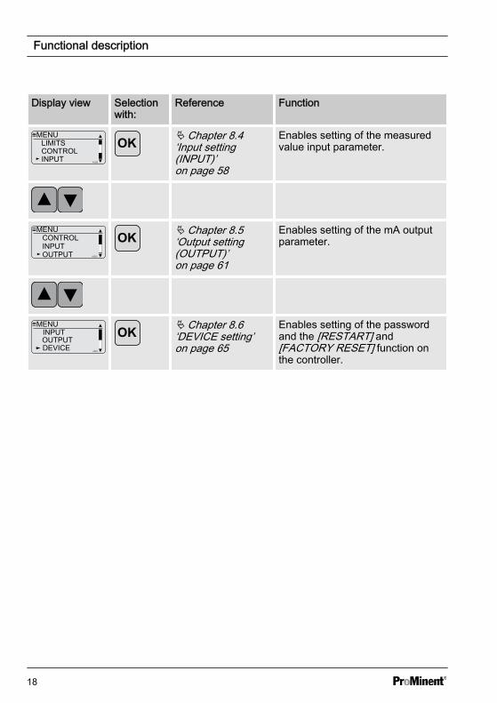
≡MENULIMITSCONTROLINPUT A0328
Ä Chapter 8.4‘Input setting(INPUT)’on page 58
Enables setting of the measuredvalue input parameter.
≡MENU
OUTPUT
CONTROLINPUT
A0330
Ä Chapter 8.5‘Output setting(OUTPUT)’on page 61
Enables setting of the mA outputparameter.
≡MENU
DEVICEOUTPUTINPUT
A0331
Ä Chapter 8.6‘DEVICE setting’on page 65
Enables setting of the passwordand the [RESTART] and[FACTORY RESET] function onthe controller.
Functional description
18
5 Assembly and installationn User qualification, mechanical instal‐
lation: trained qualified personnel, seeÄ Chapter 2.2 ‘Users' qualifications’on page 10
n User qualification, electrical installa‐tion: Electrical technician, seeÄ Chapter 2.2 ‘Users' qualifications’on page 10
CAUTION!
Possible consequence: Materialdamage.
The hinge between the front andrear part of the housing cannotabsorb high levels of mechanicalloading. When working on the con‐troller, hold the top section of thecontroller housing firmly.
NOTICE!
Mounting position and conditions– The (electrical) installation
should only take place after(mechanical) installation
– Ensure that there is unim‐peded access for operation
– Ensure safe and low-vibrationfastening
– Avoid direct sunlight– Permissible ambient tempera‐
ture of the controller at theinstallation location: - 10 ...60℃ at max. 95 % relative airhumidity (non-condensing)
– Take into consideration thepermissible ambient tempera‐ture of the connected sensorsand other components
Read-off and operating posi‐tion– Mount the device in a favour‐
able position for reading andoperating (preferably at eyelevel)
Mounting position– Leave sufficient free space for
the cables
Packaging materialDispose of packaging material inan environmentally responsibleway. All packaging componentscarry the corresponding recyclingcode .
Assembly and installation
19
5.1 Scope of deliveryThe following parts belong to the standard scope of delivery of a DULCOMETER® Com‐pact Controller.
Description Quantity
Assembled device 1
Cable connection set DMTa/DXMa (metr.) 1
Operating instructions 1
5.2 Mounting (mechanical)The DULCOMETER® Compact Controller is suitable for mounting on a wall, pipe or con‐trol panel.
Tab. 2: Mounting materials (contained in the scope of supply):Description Quantity
Wall/tube retaining bracket 1
Round head screws 5x45 mm 2
Washer 5.3 2
Rawlplug Ø 8 mm, plastic 2
5.2.1 Wall mountingMounting (mechanical)
Assembly and installation
20
2
1
A0273
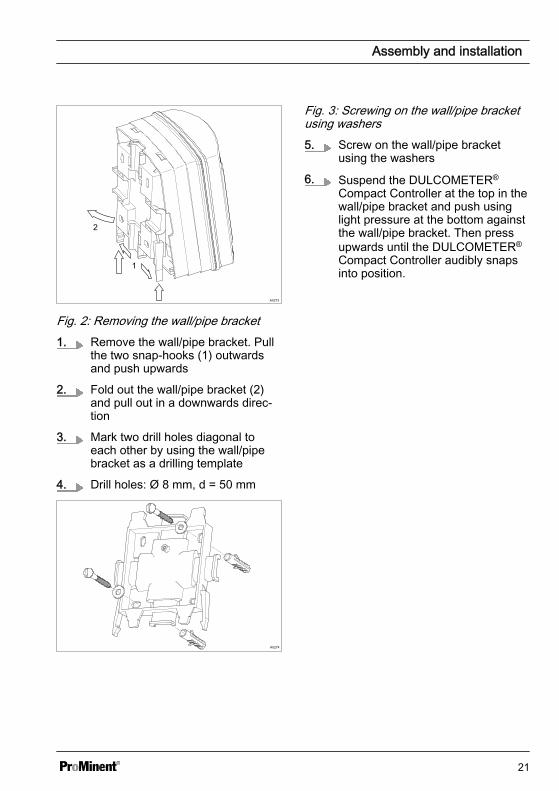
Fig. 2: Removing the wall/pipe bracket1. Remove the wall/pipe bracket. Pull
the two snap-hooks (1) outwardsand push upwards
2. Fold out the wall/pipe bracket (2)and pull out in a downwards direc‐tion
3. Mark two drill holes diagonal toeach other by using the wall/pipebracket as a drilling template
4. Drill holes: Ø 8 mm, d = 50 mm
A0274
Fig. 3: Screwing on the wall/pipe bracketusing washers5. Screw on the wall/pipe bracket
using the washers
6. Suspend the DULCOMETER®
Compact Controller at the top in thewall/pipe bracket and push usinglight pressure at the bottom againstthe wall/pipe bracket. Then pressupwards until the DULCOMETER®
Compact Controller audibly snapsinto position.
Assembly and installation
21
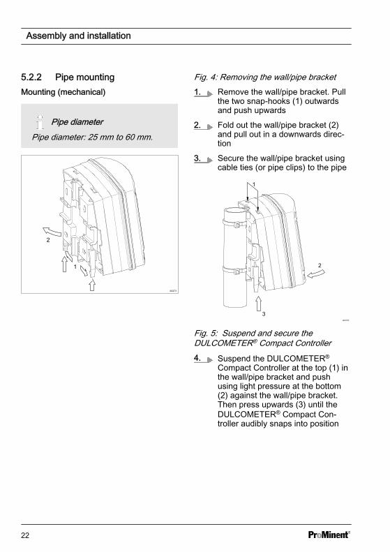
5.2.2 Pipe mountingMounting (mechanical)
Pipe diameterPipe diameter: 25 mm to 60 mm.
2
1
A0273
Fig. 4: Removing the wall/pipe bracket1. Remove the wall/pipe bracket. Pull
the two snap-hooks (1) outwardsand push upwards
2. Fold out the wall/pipe bracket (2)and pull out in a downwards direc‐tion
3. Secure the wall/pipe bracket usingcable ties (or pipe clips) to the pipe
A0275
3
2
1
Fig. 5: Suspend and secure theDULCOMETER® Compact Controller4. Suspend the DULCOMETER®
Compact Controller at the top (1) inthe wall/pipe bracket and pushusing light pressure at the bottom(2) against the wall/pipe bracket.Then press upwards (3) until theDULCOMETER® Compact Con‐troller audibly snaps into position
Assembly and installation
22
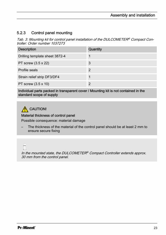
5.2.3 Control panel mountingTab. 3: Mounting kit for control panel installation of the DULCOMETER® Compact Con‐troller: Order number 1037273Description Quantity
Drilling template sheet 3872-4 1
PT screw (3.5 x 22) 3
Profile seals 2
Strain relief strip DF3/DF4 1
PT screw (3.5 x 10) 2
Individual parts packed in transparent cover / Mounting kit is not contained in thestandard scope of supply
CAUTION!
Material thickness of control panelPossible consequence: material damage
– The thickness of the material of the control panel should be at least 2 mm toensure secure fixing
In the mounted state, the DULCOMETER® Compact Controller extends approx.30 mm from the control panel.
Assembly and installation
23
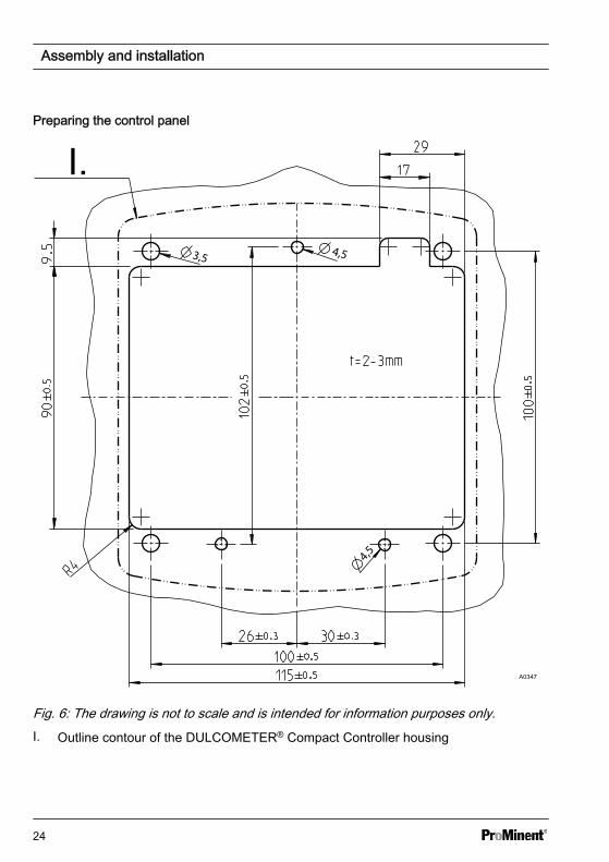
Preparing the control panel
I.
A0347
Fig. 6: The drawing is not to scale and is intended for information purposes only.I. Outline contour of the DULCOMETER® Compact Controller housing
Assembly and installation
24
1. Mark the exact position of the DULCOMETER® Compact Controller on the controlpanel using the drilling template
2.
Core holeAdhere to the 3.5 mm Ø as the core hole diameter for screwing in the fixingbolts.
Drill four holes for the bolts for the top section of the controller housing using a 3.5mm Ø drill bit
3. Drill three holes for the bolts for the bottom section of the controller housing usinga 4.5 mm Ø drill bit
4. Drill four holes using an 8 mm Ø drill bit and use a jigsaw to cut the cut-out
ð Deburr all the edges.
Assembly and installation
25
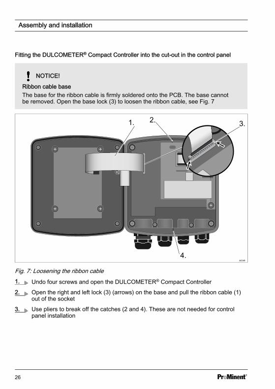
Fitting the DULCOMETER® Compact Controller into the cut-out in the control panel
NOTICE!
Ribbon cable baseThe base for the ribbon cable is firmly soldered onto the PCB. The base cannotbe removed. Open the base lock (3) to loosen the ribbon cable, see Fig. 7
1. 2. 3.
4.
Fig. 7: Loosening the ribbon cable1. Undo four screws and open the DULCOMETER® Compact Controller
2. Open the right and left lock (3) (arrows) on the base and pull the ribbon cable (1)out of the socket
3. Use pliers to break off the catches (2 and 4). These are not needed for controlpanel installation
Assembly and installation
26
1.2.
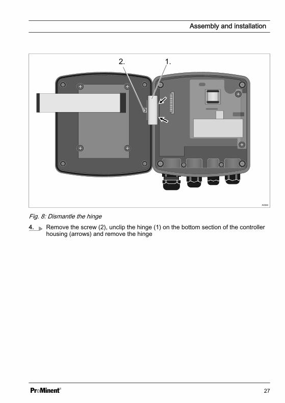
Fig. 8: Dismantle the hinge4. Remove the screw (2), unclip the hinge (1) on the bottom section of the controller
housing (arrows) and remove the hinge
Assembly and installation
27
A03601.
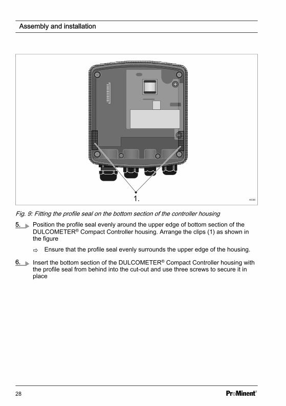
Fig. 9: Fitting the profile seal on the bottom section of the controller housing5. Position the profile seal evenly around the upper edge of bottom section of the
DULCOMETER® Compact Controller housing. Arrange the clips (1) as shown inthe figure
ð Ensure that the profile seal evenly surrounds the upper edge of the housing.
6. Insert the bottom section of the DULCOMETER® Compact Controller housing withthe profile seal from behind into the cut-out and use three screws to secure it inplace
Assembly and installation
28
A0351
1.
2.1.
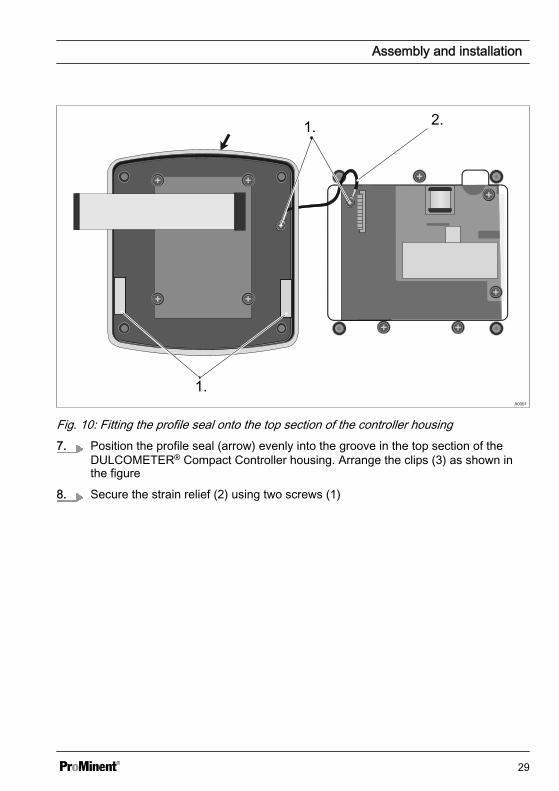
Fig. 10: Fitting the profile seal onto the top section of the controller housing7. Position the profile seal (arrow) evenly into the groove in the top section of the
DULCOMETER® Compact Controller housing. Arrange the clips (3) as shown inthe figure
8. Secure the strain relief (2) using two screws (1)
Assembly and installation
29
A0352
1.
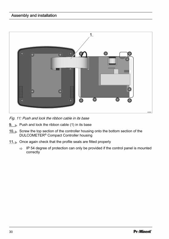
Fig. 11: Push and lock the ribbon cable in its base9. Push and lock the ribbon cable (1) in its base
10. Screw the top section of the controller housing onto the bottom section of theDULCOMETER® Compact Controller housing
11. Once again check that the profile seals are fitted properly
ð IP 54 degree of protection can only be provided if the control panel is mountedcorrectly
Assembly and installation
30
5.3 Installation (electrical)
WARNING!
Live parts!Possible consequence: Fatal orvery serious injuries
– Measure: Disconnect the elec‐trical power supply to thedevice before opening thehousing and secure to preventunintentional reconnection
– Disconnect damaged or defec‐tive devices or devices thathave been tampered with andprevent unintended reconnec‐tion
– The provision of a suitable iso‐lating device (emergency-offswitch, etc.) is the responsi‐bility of the plant operator
The signal leads of the controllermay not be routed alongside inter‐ference-prone cabling. This couldlead to controller malfunctions.
Assembly and installation
31
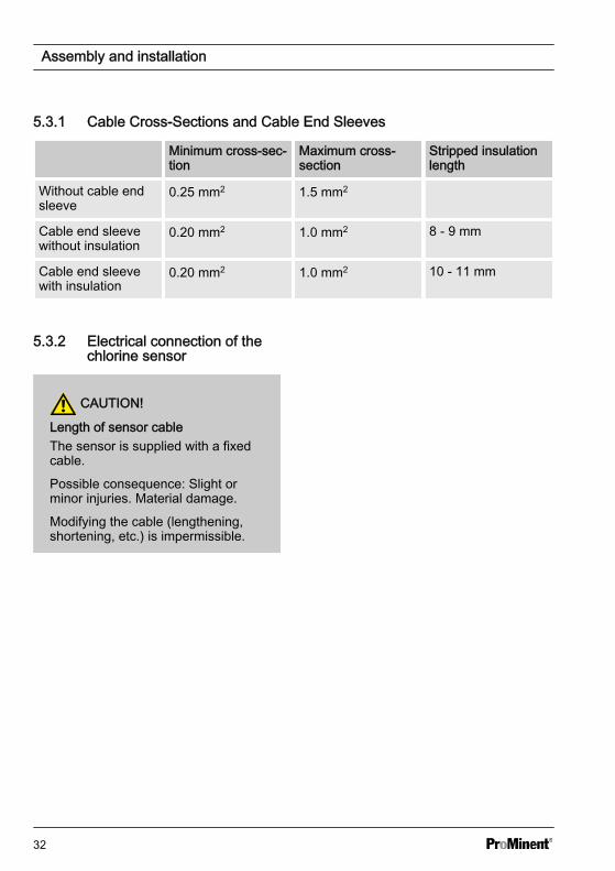
5.3.1 Cable Cross-Sections and Cable End Sleeves
Minimum cross-sec‐tion
Maximum cross-section
Stripped insulationlength
Without cable endsleeve
0.25 mm2 1.5 mm2
Cable end sleevewithout insulation
0.20 mm2 1.0 mm2 8 - 9 mm
Cable end sleevewith insulation
0.20 mm2 1.0 mm2 10 - 11 mm
5.3.2 Electrical connection of thechlorine sensor
CAUTION!
Length of sensor cableThe sensor is supplied with a fixedcable.
Possible consequence: Slight orminor injuries. Material damage.
Modifying the cable (lengthening,shortening, etc.) is impermissible.
Assembly and installation
32
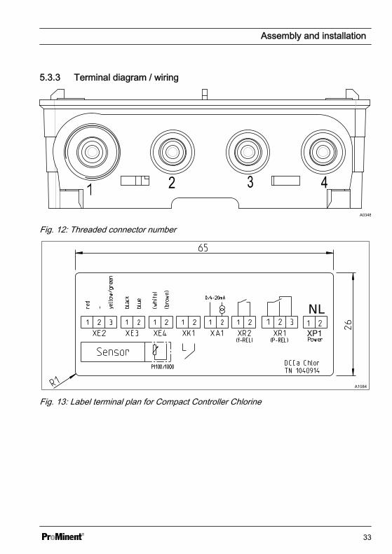
5.3.3 Terminal diagram / wiring
A0348
Fig. 12: Threaded connector number
A1084
Fig. 13: Label terminal plan for Compact Controller Chlorine
Assembly and installation
33
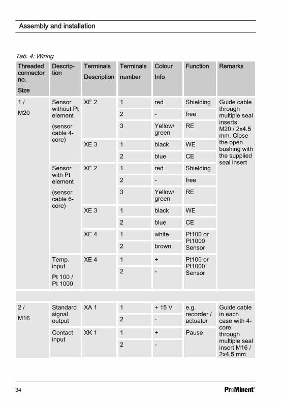
Tab. 4: WiringThreadedconnectorno.
Size
Descrip‐tion
Terminals
Description
Terminals
number
Colour
Info
Function Remarks
1 /
M20
Sensorwithout Ptelement
(sensorcable 4-core)
XE 2 1 red Shielding Guide cablethroughmultiple sealinsertsM20 / 2x4.5mm. Closethe openbushing withthe suppliedseal insert
2 - free
3 Yellow/green
RE
XE 3 1 black WE
2 blue CE
Sensorwith Ptelement
(sensorcable 6-core)
XE 2 1 red Shielding
2 - free
3 Yellow/green
RE
XE 3 1 black WE
2 blue CE
XE 4 1 white Pt100 orPt1000Sensor2 brown
Temp.input
Pt 100 /Pt 1000
XE 4 1 + Pt100 orPt1000Sensor2 -
2 /
M16
Standardsignaloutput
XA 1 1 + 15 V e.g.recorder /actuator
Guide cablein eachcase with 4-corethroughmultiple sealinsert M16 /2x4.5 mm.
2 -
Contactinput
XK 1 1 + Pause
2 -
Assembly and installation
34
Threadedconnectorno.
Size
Descrip‐tion
Terminals
Description
Terminals
number
Colour
Info
Function Remarks
Relayoutput
(f-relay)
XR 2 1 Fre‐quencycontrolledmeteringpump
2
* To achieve protection class IP 67, please use original Prominent cable, part number1036759
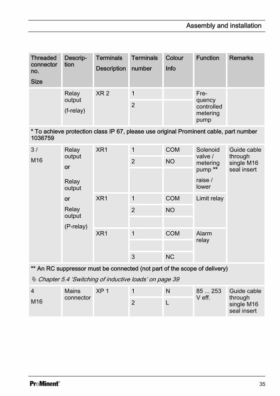
3 /
M16
Relayoutput
or
Relayoutput
or
Relayoutput
(P-relay)
XR1 1 COM Solenoidvalve /meteringpump **
raise /lower
Guide cablethroughsingle M16seal insert
2 NO
XR1 1 COM Limit relay
2 NO
XR1 1 COM Alarmrelay
3 NC
** An RC suppressor must be connected (not part of the scope of delivery)
Ä Chapter 5.4 ‘Switching of inductive loads’ on page 39
4
M16
Mainsconnector
XP 1 1 N 85 ... 253V eff.
Guide cablethroughsingle M16seal insert
2 L
Assembly and installation
35
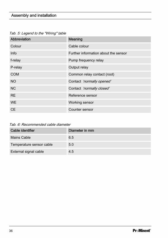
Tab. 5: Legend to the "Wiring" tableAbbreviation Meaning
Colour Cable colour
Info Further information about the sensor
f-relay Pump frequency relay
P-relay Output relay
COM Common relay contact (root)
NO Contact ‘normally opened’
NC Contact ‘normally closed’
RE Reference sensor
WE Working sensor
CE Counter sensor
Tab. 6: Recommended cable diameterCable identifier Diameter in mm
Mains Cable 6.5
Temperature sensor cable 5.0
External signal cable 4.5
Assembly and installation
36
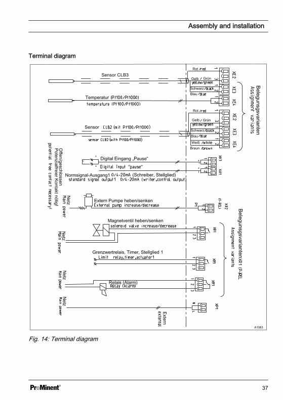
Terminal diagram
Belegunsgsvarianten
Belegunsgsvarianten
Rot
Rot
Gelb
Gelb Grün
Grün
Schwarz
SchwarzBlau
Blau
WeißBraun
Temperatur
Sensor
Digital Eingang „Pause“
Normsignal-Ausgang1 (Schreiber, Stellglied)
Extern Pumpe heben/senken
Magnetventil heben/senken
Grenzwertrelais, Timer, Stellglied 1
Relais (Alarm)
Netz
Netz
Offen/geschlossen
Potenzialfreier Kontakt nötig!
Netz
Netz
Extern
A1083
Fig. 14: Terminal diagram
Assembly and installation
37
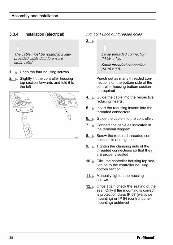
5.3.4 Installation (electrical)
The cable must be routed in a site-provided cable duct to ensurestrain relief
1. Undo the four housing screws
2. Slightly lift the controller housingtop section forwards and fold it tothe left
A0272
Fig. 15: Punch out threaded holes3.
Large threaded connection(M 20 x 1.5)Small threaded connection(M 16 x 1.5)
Punch out as many threaded con‐nections on the bottom side of thecontroller housing bottom sectionas required
4. Guide the cable into the respectivereducing inserts.
5. Insert the reducing inserts into thethreaded connectors
6. Guide the cable into the controller.
7. Connect the cable as indicated inthe terminal diagram
8. Screw the required threaded con‐nections in and tighten
9. Tighten the clamping nuts of thethreaded connections so that theyare properly sealed
10. Click the controller housing top sec‐tion on to the controller housingbottom section
11. Manually tighten the housingscrews
12. Once again check the seating of theseal. Only if the mounting is correct,is protection class IP 67 (wall/pipemounting) or IP 54 (control panelmounting) achieved
Assembly and installation
38
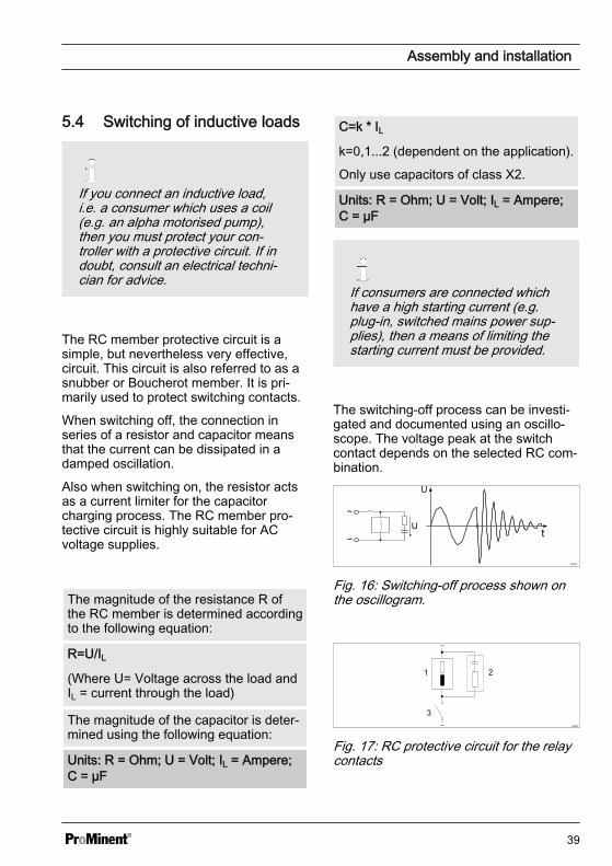
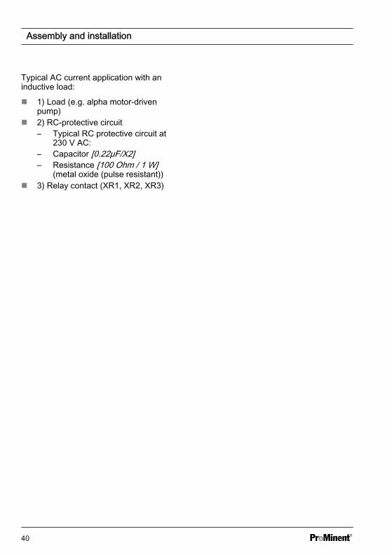
5.4 Switching of inductive loads
If you connect an inductive load,i.e. a consumer which uses a coil(e.g. an alpha motorised pump),then you must protect your con‐troller with a protective circuit. If indoubt, consult an electrical techni‐cian for advice.
The RC member protective circuit is asimple, but nevertheless very effective,circuit. This circuit is also referred to as asnubber or Boucherot member. It is pri‐marily used to protect switching contacts.
When switching off, the connection inseries of a resistor and capacitor meansthat the current can be dissipated in adamped oscillation.
Also when switching on, the resistor actsas a current limiter for the capacitorcharging process. The RC member pro‐tective circuit is highly suitable for ACvoltage supplies.
The magnitude of the resistance R ofthe RC member is determined accordingto the following equation:
R=U/IL(Where U= Voltage across the load andIL = current through the load)
The magnitude of the capacitor is deter‐mined using the following equation:
Units: R = Ohm; U = Volt; IL = Ampere;C = µF
C=k * ILk=0,1...2 (dependent on the application).
Only use capacitors of class X2.
Units: R = Ohm; U = Volt; IL = Ampere;C = µF
If consumers are connected whichhave a high starting current (e.g.plug-in, switched mains power sup‐plies), then a means of limiting thestarting current must be provided.
The switching-off process can be investi‐gated and documented using an oscillo‐scope. The voltage peak at the switchcontact depends on the selected RC com‐bination.
A0842
Fig. 16: Switching-off process shown onthe oscillogram.
A0835
Fig. 17: RC protective circuit for the relaycontacts
Assembly and installation
39
Typical AC current application with aninductive load:
n 1) Load (e.g. alpha motor-drivenpump)
n 2) RC-protective circuit– Typical RC protective circuit at
230 V AC:– Capacitor [0.22µF/X2]– Resistance [100 Ohm / 1 W]
(metal oxide (pulse resistant))n 3) Relay contact (XR1, XR2, XR3)
Assembly and installation
40
6 Commissioningn User qualification: trained user, see
Ä Chapter 2.2 ‘Users' qualifications’on page 10
WARNING!
Sensor run in periodsThis can result in hazardous incor‐rect metering
– Correct measuring and dosingis only possible if the sensor isworking perfectly
– Please read the operatingmanual for the sensor
– The sensor must be calibratedafter commissioning
Following completion of mechanical andelectrical assembly, the controller shouldbe integrated into the measuring point.
6.1 Initial commissioningWhen the controller is first switched on,the controller is in STOP state.
Subsequently the control settings and set‐ting of the various, process-dependentparameters is undertaken.
6.2 Setting the controller duringcommissioning
NOTICE!
Reset to factory settingsWhen switching over the meteringdirection, all actuators in the con‐troller are reset to the factory set‐tings for the selected meteringdirection.
For safety reasons, all actuatorsare deactivated. The base load isreset to 0 %. All parametersrelating to the actuator, are reset tothe factory setting.
Consequently all parametersrelating to the actuator, must bereset.
The controller only controls ‘one-way’ .Only one position or one negative controlvariable can be calculated. The directionof the control variable is set in the‘PUMP’ menu. There is no dead zone. Inthis sense, control cannot be‘deactivated’ (except with ‘STOP’ or‘PAUSE’ ).The value of the P-proportion of the con‐trol (Xp) is specified for the controller inthe corresponding measured variable unit.
For pure P-control and a separationbetween the set and actual values, whichcorresponds to the Xp value, the calcu‐lated control variable is +100% (with set‐ting ‘raise’ ) and -100% (with setting‘lower’ ).
Commissioning
41
7 Operating diagram7.1 Overview of equipment/Control elementsn User qualification: instructed user, see Ä Chapter 2.2 ‘Users' qualifications’
on page 10
A02916
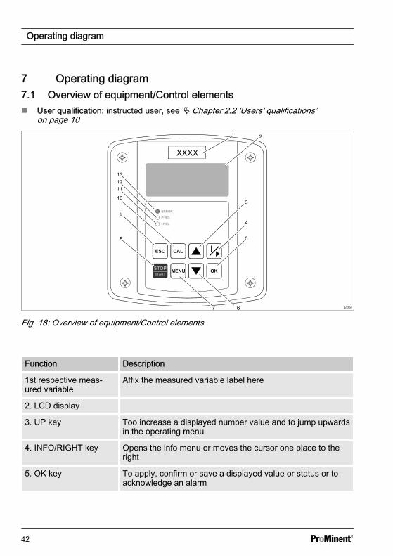
Fig. 18: Overview of equipment/Control elements
Function Description
1st respective meas‐ured variable
Affix the measured variable label here
2. LCD display
3. UP key Too increase a displayed number value and to jump upwardsin the operating menu
4. INFO/RIGHT key Opens the info menu or moves the cursor one place to theright
5. OK key To apply, confirm or save a displayed value or status or toacknowledge an alarm
Operating diagram
42
Function Description
6. DOWN key Too decrease a displayed number value and to jump down inthe operating menu
7. MENU key Accesses the controller operating menu
8. STOP/START key Starts and stops control and metering function
9. ESC key Jumps a level back in the operating menu, without storage orchanging entries or values
10. CAL key For accessing the calibration menu and navigating within thecalibration menu.
11. f-REL LED Shows the activated state of the f-relay
12. P-REL LED Shows the activated state of the P-relay
13. ERROR LED Indicates a controller error state. A text message is displayedsimultaneously in the LCD continuous display
7.2 Adjusting display contrastIf the DULCOMETER® Compact Controlleris set to ‘continuous display’ , you can setthe contrast of the LCD-display. Bypressing the key you can adjust theLCD display contrast so it is darker. Bypressing the key you can adjust theLCD display contrast so it is lighter. Hereeach key press represents a contrastlevel. I.e. the key must be pressed oncefor each contrast level.
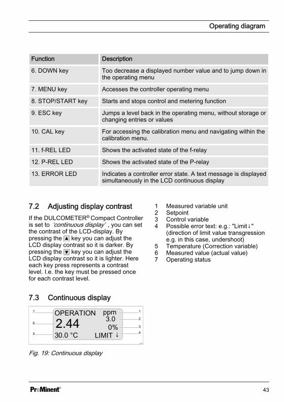
7.3 Continuous display
A1003
1
2
345
6
7
Fig. 19: Continuous display
1 Measured variable unit2 Setpoint3 Control variable4 Possible error text: e.g.: "Limit↓"
(direction of limit value transgressione.g. in this case, undershoot)
5 Temperature (Correction variable)6 Measured value (actual value)7 Operating status
Operating diagram
43
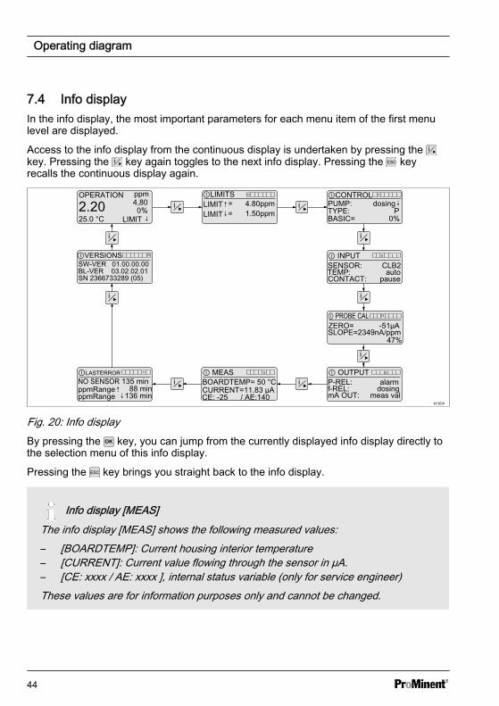
7.4 Info displayIn the info display, the most important parameters for each menu item of the first menulevel are displayed.
Access to the info display from the continuous display is undertaken by pressing the key. Pressing the key again toggles to the next info display. Pressing the keyrecalls the continuous display again.
A1004
OPERATION ppm
2.2025.0 °C
4,800%
LIMIT ↓
ⒾLIMITSLIMIT↑= 4.80ppmLIMIT↓= 1.50ppm
SENSOR: CLB2TEMP: auto
CURRENT=11.83 µAP-REL: alarmmA OUT: meas val
ⒾCONTROLPUMP: dosing↓TYPE: PBASIC= 0%
Ⓘ INPUT
CONTACT: pause
Ⓘ OUTPUT
f-REL: dosing
Ⓘ MEASⒾLASTERROR
ⒾVERSIONS
NO SENSOR 135 min
SW-VER 01.00.00.00
SN 2366733289 (05)
ppmRange↑ 88 minppmRange ↓136 min
BL-VER 03.02.02.01
BOARDTEMP= 50 °C
ZERO= -51µASLOPE=2349nA/ppm
Ⓘ PROBE CAL
47%
CE: -25 / AE:140
Fig. 20: Info displayBy pressing the key, you can jump from the currently displayed info display directly tothe selection menu of this info display.
Pressing the key brings you straight back to the info display.
Info display [MEAS]The info display [MEAS] shows the following measured values:– [BOARDTEMP]: Current housing interior temperature– [CURRENT]: Current value flowing through the sensor in µA.– [CE: xxxx / AE: xxxx ], internal status variable (only for service engineer)These values are for information purposes only and cannot be changed.
Operating diagram
44
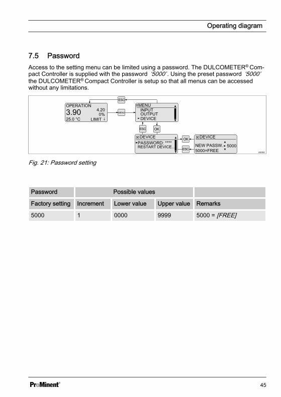
7.5 PasswordAccess to the setting menu can be limited using a password. The DULCOMETER® Com‐pact Controller is supplied with the password ‘5000’ . Using the preset password ‘5000’the DULCOMETER® Compact Controller is setup so that all menus can be accessedwithout any limitations.
A0353
OPERATION
3.9025.0 °C
4.200%
LIMIT ↓MENU
≡MENU
DEVICEOUTPUTINPUT
※DEVICEPASSWORD: ****
※DEVICE
NEW PASSW. 5000=FREE
RESTART DEVICE... 5000
Fig. 21: Password setting
Password Possible values
Factory setting Increment Lower value Upper value Remarks
5000 1 0000 9999 5000 = [FREE]
Operating diagram
45
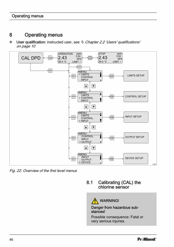
8 Operating menusn User qualification: instructed user, see Ä Chapter 2.2 ‘Users' qualifications’
on page 10
A0998
Fig. 22: Overview of the first level menus
8.1 Calibrating (CAL) thechlorine sensor
WARNING!
Danger from hazardous sub‐stances!Possible consequence: Fatal orvery serious injuries.
Operating menus
46
Please ensure when handling haz‐ardous substances that you haveread the latest safety data sheetsprovided by the manufacture of thehazardous substance. The actionsrequired are described in thesafety data sheet. Check the safetydata sheet regularly and replace, ifnecessary, as the hazard potentialof a substance can be re-evaluatedat any time based on new findings.
The system operator is responsiblefor ensuring that these safety datasheets are available and that theyare kept up to date, as well as forproducing an associated hazardassessment for the workstationsaffected.
Sensor slope / sensor zeropointOnly the sensor slope can be cali‐brated.The sensor zero point can be bal‐anced using the function[CHECK ZERO].
Correct sensor operation– Correct measuring and
metering is only possible if thesensor is working perfectly
– Observe the sensor operatinginstructions
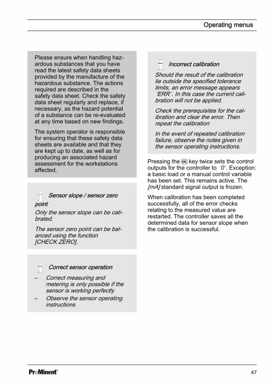
Incorrect calibrationShould the result of the calibrationlie outside the specified tolerancelimits, an error message appears‘ERR’ . In this case the current cali‐bration will not be applied.Check the prerequisites for the cal‐ibration and clear the error. Thenrepeat the calibrationIn the event of repeated calibrationfailure, observe the notes given inthe sensor operating instructions.
Pressing the key twice sets the controloutputs for the controller to ‘0’ . Exception:a basic load or a manual control variablehas been set. This remains active. The[mA] standard signal output is frozen.
When calibration has been completedsuccessfully, all of the error checksrelating to the measured value arerestarted. The controller saves all thedetermined data for sensor slope whenthe calibration is successful.
Operating menus
47
8.1.1 Sensor slope calibration
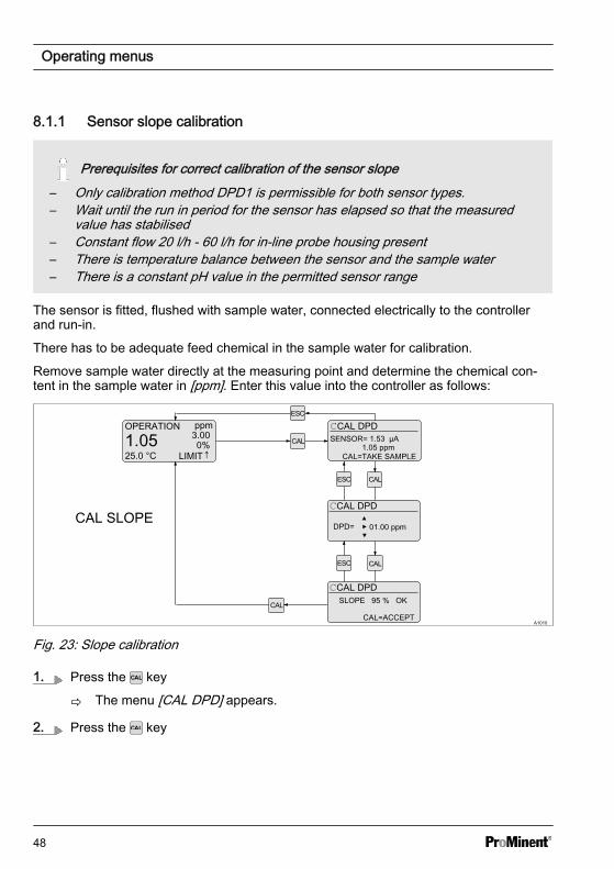
Prerequisites for correct calibration of the sensor slope– Only calibration method DPD1 is permissible for both sensor types.– Wait until the run in period for the sensor has elapsed so that the measured
value has stabilised– Constant flow 20 l/h - 60 l/h for in-line probe housing present– There is temperature balance between the sensor and the sample water– There is a constant pH value in the permitted sensor range
The sensor is fitted, flushed with sample water, connected electrically to the controllerand run-in.
There has to be adequate feed chemical in the sample water for calibration.
Remove sample water directly at the measuring point and determine the chemical con‐tent in the sample water in [ppm]. Enter this value into the controller as follows:
A1010
OPERATION ppm
1.0525.0 °C
3.000%
LIMIT↑
CAL DPD
1.05 ppmCAL=TAKE SAMPLE
SENSOR= 1.53 µA
CAL DPD
DPD= 01.00 ppm
CAL DPDSLOPE 95 % OK
CAL=ACCEPT
Fig. 23: Slope calibration
1. Press the key
ð The menu [CAL DPD] appears.
2. Press the key
Operating menus
48
ð
At the time of taking the sample, you must have navigated to this point[CAL=TAKE SAMPLE] and then press the key so that the currentmeasured value is frozen.
The menu for entering the determined DPD value appears.
3. Take a water sample from the in-line probe housing and carry out the [DPD] refer‐ence measurement within no more than 15 minutes. The shorter this period oftime, the greater the accuracy of the measurement.
The precision of the calibration can be checked by carrying out repeatedmeasurements and observing the range of results. Determining the permis‐sible precision is the responsibility of the plant operator
4. Enter the determined value into the controller using the , and keys.
5. After entering the value, press the key.
ð The display indicating the calculated slope in [%] appears.
6. Press the key
ð The calculated sensor slope is accepted by the controller and the continuousdisplay is shown again.
Operating menus
49
Sensor status
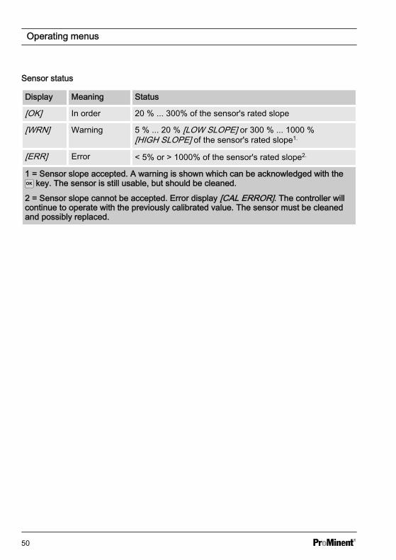
Display Meaning Status
[OK] In order 20 % ... 300% of the sensor's rated slope
[WRN] Warning 5 % ... 20 % [LOW SLOPE] or 300 % ... 1000 %[HIGH SLOPE] of the sensor's rated slope1.
[ERR] Error < 5% or > 1000% of the sensor's rated slope2.
1 = Sensor slope accepted. A warning is shown which can be acknowledged with the key. The sensor is still usable, but should be cleaned.
2 = Sensor slope cannot be accepted. Error display [CAL ERROR]. The controller willcontinue to operate with the previously calibrated value. The sensor must be cleanedand possibly replaced.
Operating menus
50
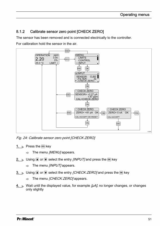
8.1.2 Calibrate sensor zero point [CHECK ZERO]The sensor has been removed and is connected electrically to the controller.
For calibration hold the sensor in the air.
A1087
OPERATION ppm
2.2025.0 °C
3.000%
LIMIT ↓MENU
≡MENULIMITSCONTROLINPUT
※INPUTSENSOR: CLB2↳FILTER: 3s
ZERO= +81 pA OK
↳CHECK ZERO...
CAL=ACCEPT OK=RESET
ℂ CHECK ZEROSENSOR= +2.27 µA
1.87 ppmCAL=CHECK ZERO
ℂ CHECK ZEROZERO= 0 nA OK
CAL=ACCEPT
ℂ CHECK ZERO
Fig. 24: Calibrate sensor zero point [CHECK ZERO]
1. Press the key
ð The menu [MENU] appears.
2. Using or select the entry [INPUT] and press the key
ð The menu [INPUT] appears.
3. Using or select the entry [CHECK ZERO] and press the key
ð The menu [CHECK ZERO] appears.
4. Wait until the displayed value, for example [µA], no longer changes, or changesonly slightly
Operating menus
51
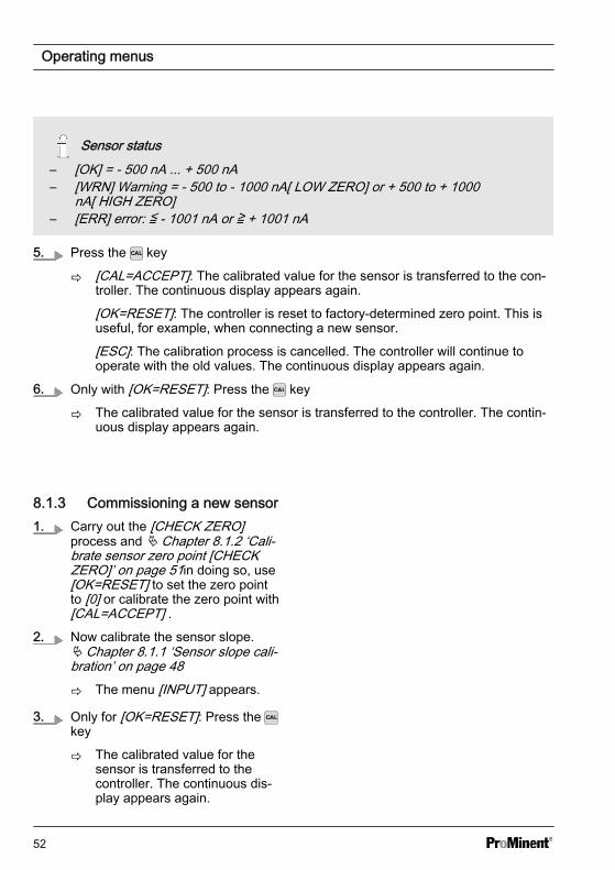
Sensor status– [OK] = - 500 nA ... + 500 nA– [WRN] Warning = - 500 to - 1000 nA[ LOW ZERO] or + 500 to + 1000
nA[ HIGH ZERO]– [ERR] error: ≦ - 1001 nA or ≧ + 1001 nA
5. Press the key
ð [CAL=ACCEPT]: The calibrated value for the sensor is transferred to the con‐troller. The continuous display appears again.
[OK=RESET]: The controller is reset to factory-determined zero point. This isuseful, for example, when connecting a new sensor.
[ESC]: The calibration process is cancelled. The controller will continue tooperate with the old values. The continuous display appears again.
6. Only with [OK=RESET]: Press the key
ð The calibrated value for the sensor is transferred to the controller. The contin‐uous display appears again.
8.1.3 Commissioning a new sensor1. Carry out the [CHECK ZERO]
process and Ä Chapter 8.1.2 ‘Cali‐brate sensor zero point [CHECKZERO]’ on page 51in doing so, use[OK=RESET] to set the zero pointto [0] or calibrate the zero point with[CAL=ACCEPT] .
2. Now calibrate the sensor slope.Ä Chapter 8.1.1 ‘Sensor slope cali‐bration’ on page 48
ð The menu [INPUT] appears.
3. Only for [OK=RESET]: Press the key
ð The calibrated value for thesensor is transferred to thecontroller. The continuous dis‐play appears again.
Operating menus
52
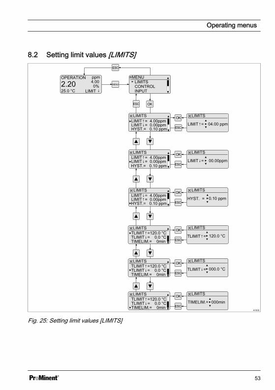
8.2 Setting limit values [LIMITS]
A1005
OPERATION ppm
2.2025.0 °C
4.000%
LIMIT ↓MENU
≡MENULIMITSCONTROLINPUT
※LIMITS
LIMIT↓= 0.00ppmLIMIT↑= 4.00ppm
HYST.= 0.10 ppm
※LIMITS
04.00 ppm
※LIMITS
LIMIT↑=
00.00ppm
※LIMITS
LIMIT↓= 0.00ppmLIMIT↑= 4.00ppm
※LIMITS
0.10 ppm
※LIMITSLIMIT↓= 4.00ppmLIMIT↑= 0.00ppm
※LIMITS
TLIMIT↓= 0.0 °CTLIMIT↑=120.0 °C
TIMELIM.= 0min
※LIMITS
HYST. =
120.0 °C
※LIMITS
TLIMIT↓= 0.0 °CTLIMIT↑=120.0 °C
TIMELIM.= 0min
※LIMITS
TIMELIM.= 000min
LIMIT↓=
※LIMITS
TLIMIT↓= 0.0 °CTLIMIT↑=120.0 °C
TIMELIM.= 0min
※LIMITS
000.0 °CTLIMIT↓=
HYST.= 0.10 ppm
HYST.= 0.10 ppm
TLIMIT↑=
Fig. 25: Setting limit values [LIMITS]
Operating menus
53
Setting Possible values
Display Startingvalue
Increment Lower value Upper value Remark
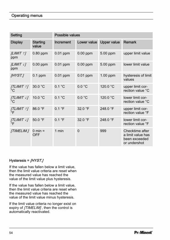
[LIMIT ↑]ppm
0.80 ppm 0.01 ppm 0.00 ppm 5.00 ppm upper limit value
[LIMIT ↓]ppm
0.00 ppm 0.01 ppm 0.00 ppm 5.00 ppm lower limit value
[HYST.] 0.1 ppm 0.01 ppm 0.01 ppm 1.00 ppm hysteresis of limitvalues
[TLIMIT ↑]°C
30.0 °C 0.1 °C 0.0 °C 120.0 °C upper limit cor‐rection value °C
[TLIMIT ↓]°C
10.0 °C 0.1 °C 0.0 °C 120.0 °C lower limit cor‐rection value °C
[TLIMIT ↑]°F
86.0 °F 0.1 °F 32.0 °F 248.0 °F upper limit cor‐rection value °F
[TLIMIT ↓]°F
50.0 °F 0.1 °F 32.0 °F 248.0 °F lower limit cor‐rection value °F
[TIMELIM.] 0 min =OFF
1 min 0 999 Checktime aftera limit value hasbeen exceededor undershot
Hysteresis = [HYST.]If the value has fallen below a limit value,then the limit value criteria are reset whenthe measured value has reached thevalue of the limit value plus hysteresis.
If the value has fallen below a limit value,then the limit value criteria are reset whenthe measured value has reached thevalue of the limit value minus hysteresis.
If the limit value criteria no longer exist onexpiry of [TIMELIM] , then the control isautomatically reactivated.
Operating menus
54
8.3 Setting the control [CONTROL]
A1006
OPERATION ppm
2.2025.0 °C
3.000%
LIMIT ↓MENU
≡MENULIMITSCONTROLINPUT
※CONTROLPUMP: dosing↓SET= 3.00ppmTYPE: P
※CONTROL
PUMP: dosing↓
※CONTROL
SET= 03.00 ppm
※CONTROL
※CONTROL
TYPE: P
※CONTROL
※CONTROL ※CONTROL
01.50 ppm
※CONTROL ※CONTROL
BASIC= +000%
PUMP: dosing↓SET= 3.00ppmTYPE: P
PUMP: dosing↓SET= 3.00ppmTYPE: P
TYPE: PID↳Xp= 1.50ppmBASIC= 0%
↳Xp=
TYPE: PID↳Xp= 1.50ppmBASIC= 0%
※CONTROL ※CONTROL
CHECKTIME= 001minCHECKTIME= 1min
↳Xp= 1.50ppmBASIC= 0%
※CONTROL ※CONTROL
↳LIMIT= = +088%CHECKTIME= 1min↳LIMIT= 87%
BASIC= 0%
dosing↑
PID
manual
※CONTROL ※CONTROLCHECKTIME= 1min↳LIMIT= 87%BOOTDELAY= 10s
BOOTDELAY= 10s
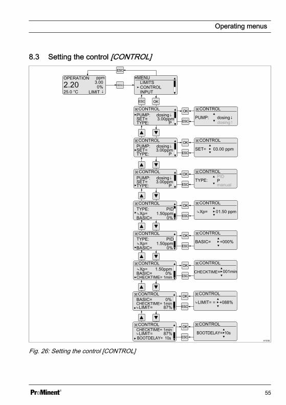
Fig. 26: Setting the control [CONTROL]
Operating menus
55
Setting Possible values
Startingvalue
Increment Lower value Uppervalue
Remark
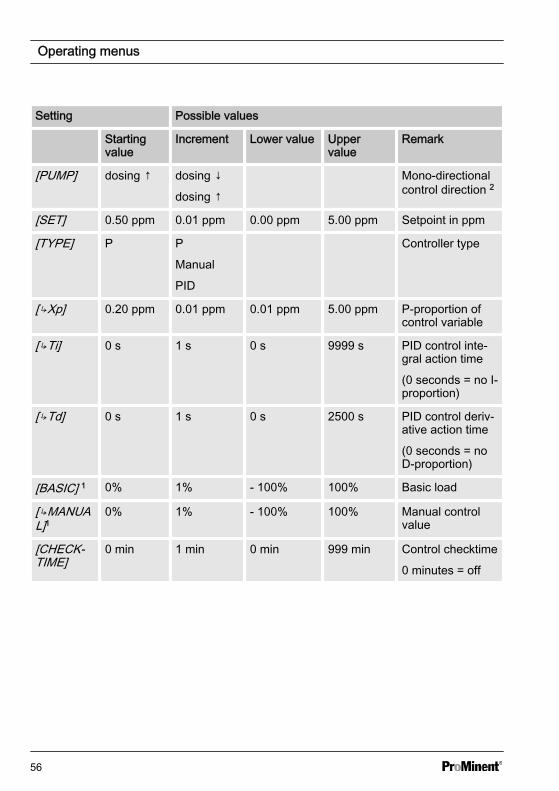
[PUMP] dosing ↑ dosing ↓
dosing ↑
Mono-directionalcontrol direction 2
[SET] 0.50 ppm 0.01 ppm 0.00 ppm 5.00 ppm Setpoint in ppm
[TYPE] P P
Manual
PID
Controller type
[↳Xp] 0.20 ppm 0.01 ppm 0.01 ppm 5.00 ppm P-proportion ofcontrol variable
[↳Ti] 0 s 1 s 0 s 9999 s PID control inte‐gral action time
(0 seconds = no I-proportion)
[↳Td] 0 s 1 s 0 s 2500 s PID control deriv‐ative action time
(0 seconds = noD-proportion)
[BASIC] 1 0% 1% - 100% 100% Basic load
[↳MANUAL]1
0% 1% - 100% 100% Manual controlvalue
[CHECK‐TIME]
0 min 1 min 0 min 999 min Control checktime
0 minutes = off
Operating menus
56
Setting Possible values
Startingvalue
Increment Lower value Uppervalue
Remark
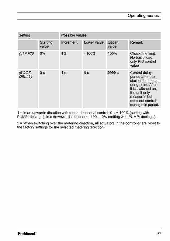
[↳LIMIT]1 0% 1% - 100% 100% Checktime limit.No basic load,only PID controlvalue
[BOOTDELAY]
0 s 1 s 0 s 9999 s Control delayperiod after thestart of the meas‐uring point. Afterit is switched on,the unit onlymeasures butdoes not controlduring this period.
1 = in an upwards direction with mono-directional control: 0 ...+ 100% (setting withPUMP: dosing↑), in a downwards direction: - 100 ... 0% (setting with PUMP: dosing↓).
2 = When switching over the metering direction, all actuators in the controller are reset tothe factory settings for the selected metering direction.
Operating menus
57
8.4 Input setting (INPUT)
A1007
OPERATION ppm
2.2025.0 °C
3.000%
LIMIT ↓MENU
≡MENULIMITSCONTROLINPUT
※INPUTSENSOR: CLB2↳FILTER: 3s
※INPUT
SENSOR: CLB2
※INPUT※INPUT
ℂ CHECK ZEROSENSOR= -2.27 µA
※INPUT
※INPUT ※INPUT
on
※INPUT ※INPUT
TEMP: auto
TEMP: auto↳TIMER: on ↳TIMER:
※INPUT ※INPUT
SENSOR: CLB2
SENSOR: CLB2
↳FILTER: 003 s
↳UNIT: °C
↳UNIT: °C
↳UNIT: °C
off
off
↳UNIT: °C°F
※INPUT ※INPUT CONTACT: pause↳POL: norm.open↳DELAY OFF= 0s
↳DELAY OFF= 0000s
※INPUT ※INPUT ↳POL: norm.open↳DELAY OFF= 0s ↳ALARM: off↳ALARM : off
on
↳CHECK ZERO...
↳FILTER: 3s↳CHECK ZERO...
↳FILTER: 3s↳CHECK ZERO...
1.87 ppmCAL=CHECK ZERO
TEMP: auto↳TIMER: on on
TEMP: auto↳TIMER: on
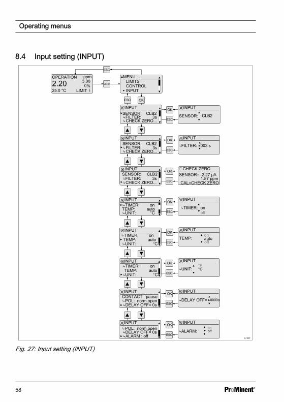
Fig. 27: Input setting (INPUT)
Operating menus
58
Setting Possible values
Display Startingvalue
Increment Lowervalue
Uppervalue
Remarks
SENSOR CLB2 CLB2
CLB3
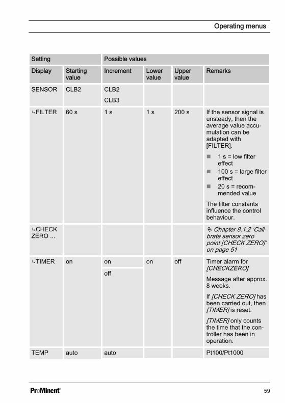
↳FILTER 60 s 1 s 1 s 200 s If the sensor signal isunsteady, then theaverage value accu‐mulation can beadapted with[FILTER].
n 1 s = low filtereffect
n 100 s = large filtereffect
n 20 s = recom‐mended value
The filter constantsinfluence the controlbehaviour.
↳CHECKZERO ...
Ä Chapter 8.1.2 ‘Cali‐brate sensor zeropoint [CHECK ZERO]’on page 51
↳TIMER on on on off Timer alarm for[CHECKZERO]Message after approx.8 weeks.
If [CHECK ZERO] hasbeen carried out, then[TIMER] is reset.
[TIMER] only countsthe time that the con‐troller has been inoperation.
off
TEMP auto auto Pt100/Pt1000
Operating menus
59
Setting Possible values
Display Startingvalue
Increment Lowervalue
Uppervalue
Remarks
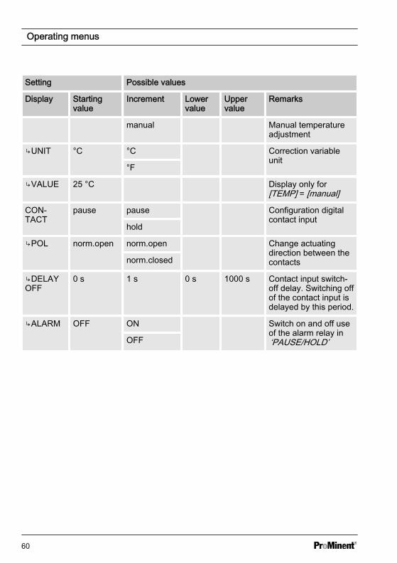
manual Manual temperatureadjustment
↳UNIT °C °C Correction variableunit
°F
↳VALUE 25 °C Display only for[TEMP] = [manual]
CON‐TACT
pause pause Configuration digitalcontact input
hold
↳POL norm.open norm.open Change actuatingdirection between thecontactsnorm.closed
↳DELAYOFF
0 s 1 s 0 s 1000 s Contact input switch-off delay. Switching offof the contact input isdelayed by this period.
↳ALARM OFF ON Switch on and off useof the alarm relay in‘PAUSE/HOLD’OFF
Operating menus
60
8.5 Output setting (OUTPUT)
A1008
OPERATION ppm
2.2025.0 °C
3.000%
LIMIT ↓MENU
≡MENU
DEVICEOUTPUTINPUT
※OUTPUTP-REL: alarm
↳PUMPMAX=180/min
※OUTPUT
P-REL:alarm
※OUTPUT※OUTPUT
※OUTPUT※OUTPUT
※OUTPUT ※OUTPUTmeas val
※OUTPUT ※OUTPUT
mA OUT: meas val mA OUT:
※OUTPUT ※OUTPUT
↳0/4mA= 0.00ppm↳20mA =05.00ppm
※OUTPUT ※OUTPUT
↳0/4mA= 00.00ppm
f-REL : dosing
↳PUMPMAX=180/min
↳PUMPMAX=180/min
f-REL: dosing
↳PUMPMAX= 180 /min
↳RANGE: 4-20mA
mA OUT: meas val
↳0/4mA= 0.00ppm↳RANGE: 4-20mA
mA OUT:
↳0/4mA= 0.00ppm↳RANGE: 4-20mA ↳RANGE: 4-20mA
※OUTPUT ※OUTPUT
↳ERROR: 23mA
↳ERROR: 23mA
↳20mA =05.00ppm↳ERROR: 23mA
↳20mA= 05.00ppm
P-REL: alarmf-REL : dosing
P-REL: alarmf-REL : dosing
limitdosingunused
unused
unusedoff
manualcorr val
0-20mA
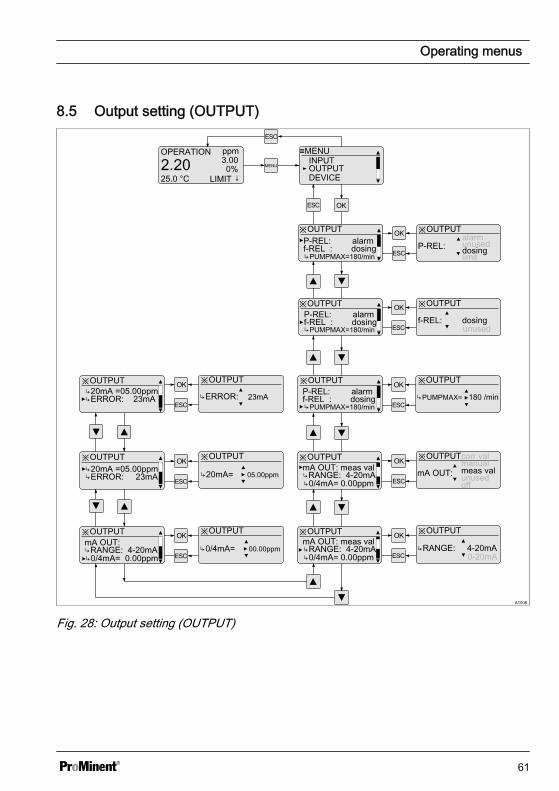
Fig. 28: Output setting (OUTPUT)
Operating menus
61
Setting Possible values
Startingvalue
Increment Lower value Uppervalue
Remarks
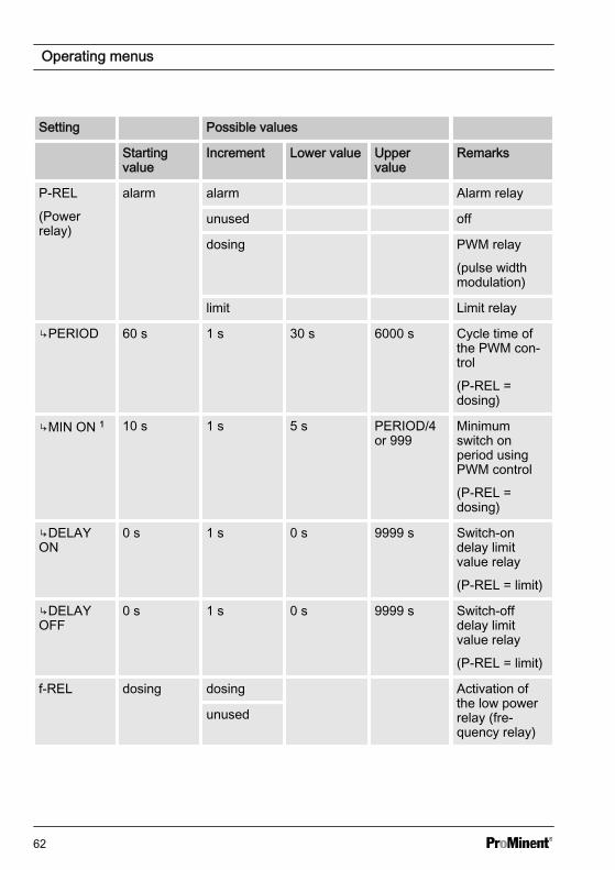
P-REL
(Powerrelay)
alarm alarm Alarm relay
unused off
dosing PWM relay
(pulse widthmodulation)
limit Limit relay
↳PERIOD 60 s 1 s 30 s 6000 s Cycle time ofthe PWM con‐trol
(P-REL =dosing)
↳MIN ON 1 10 s 1 s 5 s PERIOD/4or 999
Minimumswitch onperiod usingPWM control
(P-REL =dosing)
↳DELAYON
0 s 1 s 0 s 9999 s Switch-ondelay limitvalue relay
(P-REL = limit)
↳DELAYOFF
0 s 1 s 0 s 9999 s Switch-offdelay limitvalue relay
(P-REL = limit)
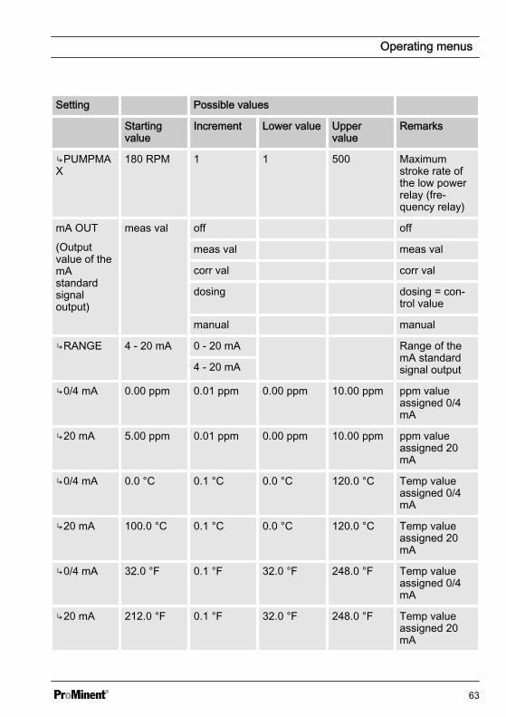
f-REL dosing dosing Activation ofthe low powerrelay (fre‐quency relay)
unused
Operating menus
62
Setting Possible values
Startingvalue
Increment Lower value Uppervalue
Remarks
↳PUMPMAX
180 RPM 1 1 500 Maximumstroke rate ofthe low powerrelay (fre‐quency relay)
mA OUT
(Outputvalue of themAstandardsignaloutput)
meas val off off
meas val meas val
corr val corr val
dosing dosing = con‐trol value
manual manual
↳RANGE 4 - 20 mA 0 - 20 mA Range of themA standardsignal output4 - 20 mA
↳0/4 mA 0.00 ppm 0.01 ppm 0.00 ppm 10.00 ppm ppm valueassigned 0/4mA
↳20 mA 5.00 ppm 0.01 ppm 0.00 ppm 10.00 ppm ppm valueassigned 20mA
↳0/4 mA 0.0 °C 0.1 °C 0.0 °C 120.0 °C Temp valueassigned 0/4mA
↳20 mA 100.0 °C 0.1 °C 0.0 °C 120.0 °C Temp valueassigned 20mA
↳0/4 mA 32.0 °F 0.1 °F 32.0 °F 248.0 °F Temp valueassigned 0/4mA
↳20 mA 212.0 °F 0.1 °F 32.0 °F 248.0 °F Temp valueassigned 20mA
Operating menus
63
Setting Possible values
Startingvalue
Increment Lower value Uppervalue
Remarks
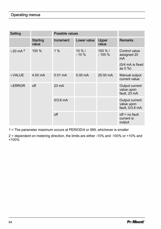
↳20 mA 2 100 % 1 % 10 % /- 10 %
100 % /- 100 %
Control valueassigned 20mA
(0/4 mA is fixedas 0 %)
↳VALUE 4.00 mA 0.01 mA 0.00 mA 25.00 mA Manual outputcurrent value
↳ERROR off 23 mA Output currentvalue uponfault, 23 mA
0/3.6 mA Output currentvalue uponfault, 0/3.6 mA
off off = no faultcurrent isoutput
1 = The parameter maximum occurs at PERIOD/4 or 999, whichever is smaller
2 = dependent on metering direction, the limits are either -10% and -100% or +10% and+100%
Operating menus
64
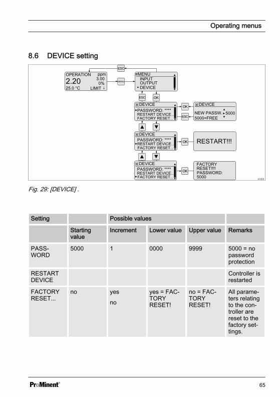
8.6 DEVICE setting
A1009
OPERATION ppm
2.2025.0 °C
3.000%
LIMIT ↓MENU
≡MENU
DEVICEOUTPUTINPUT
※DEVICEPASSWORD: ****
※DEVICE
NEW PASSW. 5000=FREE
※DEVICE
RESTART DEVICE...
PASSWORD: ****RESTART DEVICE... RESTART!!!
5000
※DEVICEPASSWORD: ****RESTART DEVICE...
FACTORY RESET!!!!
FACTORY RESET...
FACTORY RESET...
FACTORY RESET...PASSWORD: 5000
Fig. 29: [DEVICE] .
Setting Possible values
Startingvalue
Increment Lower value Upper value Remarks
PASS‐WORD
5000 1 0000 9999 5000 = nopasswordprotection
RESTARTDEVICE
Controller isrestarted
FACTORYRESET...
no yes
no
yes = FAC‐TORYRESET!
no = FAC‐TORYRESET!
All parame‐ters relatingto the con‐troller arereset to thefactory set‐tings.
Operating menus
65
9 Control parameters and functionsn User qualification: trained user, see
Ä Chapter 2.2 ‘Users' qualifications’on page 10
9.1 DULCOMETER® CompactController function states
DULCOMETER® Compact Controllerfunction states have the following priority:
n 1. ‘STOP’n 2. ‘PAUSE/HOLD’n 3. ‘CAL’ (calibration)n 4. ‘OPERATION’ (normal mode)
"CAL" (calibration) peculiarities
n Control goes to basic load, mA meas‐urement outputs are frozen
n New faults are detected, howeverthey have no effect on the alarm relayor the mA output
n Detection of measurement variablerelevant faults during ‘CAL’ (calibra‐tion process) are suppressed (e.g.LIMIT↑)
"PAUSE" peculiarities
n Control is switched to 0% control vari‐able. The I-proportion is saved
n New faults are detected, howeverthey have no effect on the alarm relayor the mA output
n Special case alarm relay in ‘PAUSE’ :If activated the output relay switchesto ‘PAUSE’ (error message CON‐TACTIN)
"HOLD" peculiarities
n Control and all other outputs arefrozen
n New faults are detected, howeverthey have no effect on the alarm relayor the mA output. However the effectof already existing faults (e.g. faultcurrent) remains
n Special case alarm relay: Activation ofthe frozen alarm relay is permitted (=no alarm), if all faults have beenacknowledged or have disappeared
n Special case alarm relay in ‘HOLD’ : Ifactivated the output relay switches to‘HOLD’ (error message CON‐TACTIN)
"STOP" peculiarities
n Control OFFn New faults are detected, however
they have no effect on the alarm relayor the mA output
n The alarm relay is switched off in‘STOP’
Peculiarities of the "START" event, i.e.switching from "STOP" to "OPERATION"(normal mode)
n Fault detection starts afresh, allexisting faults are deleted
Generally applicable information
n If the cause of a fault disappears,then the fault message in the LCDfooter disappears.
n A previously existing ‘ PAUSE/HOLD’state is not influenced by starting a‘CAL’ (calibration) process. If during‘CAL’ (calibration) the functional state‘ PAUSE/HOLD’ is released, then allstates will remain frozen until the endof the ‘CAL’ (calibration) process.
Control parameters and functions
66
n If ‘CAL’ (calibration) is started whilefunctional state ‘ OPERATION’(normal mode) is active, then thefunctional state ‘ PAUSE/HOLD’ isignored until ‘CAL’ (calibration) com‐pletes. However STOP/START ispossible at any time
n An alarm can be acknowledged orremoved as follows: By clearing allfaults by pressing the key and the
key while the continuous display isvisible
Control parameters and functions
67
9.2 STOP/START key
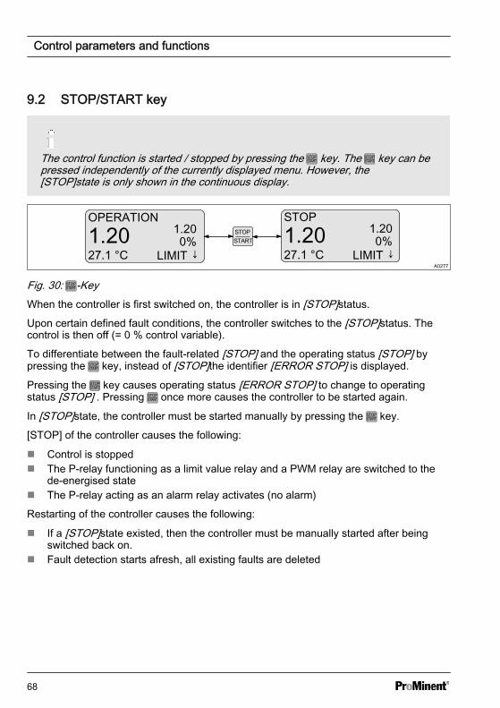
The control function is started / stopped by pressing the key. The key can bepressed independently of the currently displayed menu. However, the[STOP]state is only shown in the continuous display.
A0277
OPERATION
1.2027.1 °C
1.200%
LIMIT ↓
STOP
1.2027.1 °C
1.200%
LIMIT ↓
Fig. 30: -KeyWhen the controller is first switched on, the controller is in [STOP]status.
Upon certain defined fault conditions, the controller switches to the [STOP]status. Thecontrol is then off (= 0 % control variable).
To differentiate between the fault-related [STOP] and the operating status [STOP] bypressing the key, instead of [STOP]the identifier [ERROR STOP] is displayed.
Pressing the key causes operating status [ERROR STOP] to change to operatingstatus [STOP] . Pressing once more causes the controller to be started again.
In [STOP]state, the controller must be started manually by pressing the key.
[STOP] of the controller causes the following:
n Control is stoppedn The P-relay functioning as a limit value relay and a PWM relay are switched to the
de-energised staten The P-relay acting as an alarm relay activates (no alarm)
Restarting of the controller causes the following:
n If a [STOP]state existed, then the controller must be manually started after beingswitched back on.
n Fault detection starts afresh, all existing faults are deleted
Control parameters and functions
68
9.3 Priming (PRIME)
A0359
OPERATION
2.2012.0 °C
2.200%
LIMIT ↓
STOP
2.2012.0 °C
2.200%
LIMIT ↓
PRIME↑↑↑
2.2012.0 °C
2.200%
LIMIT ↓
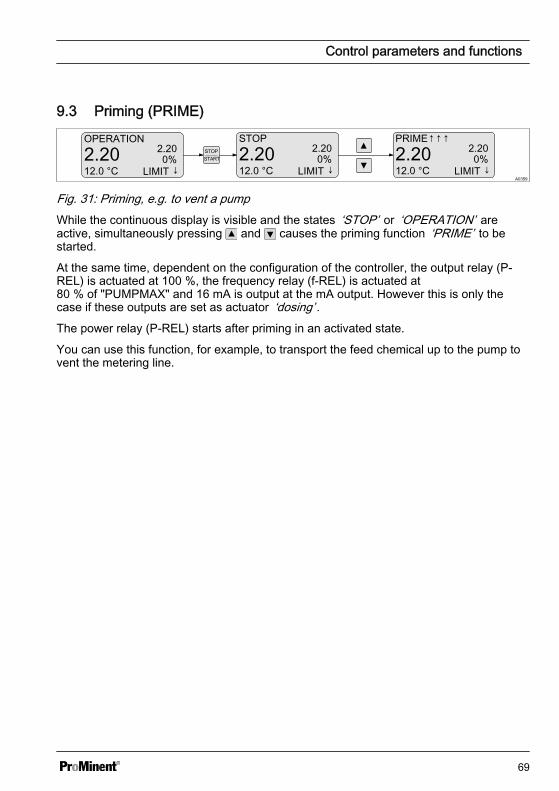
Fig. 31: Priming, e.g. to vent a pumpWhile the continuous display is visible and the states ‘STOP’ or ‘OPERATION’ areactive, simultaneously pressing and causes the priming function ‘PRIME’ to bestarted.
At the same time, dependent on the configuration of the controller, the output relay (P-REL) is actuated at 100 %, the frequency relay (f-REL) is actuated at80 % of "PUMPMAX" and 16 mA is output at the mA output. However this is only thecase if these outputs are set as actuator ‘dosing’ .The power relay (P-REL) starts after priming in an activated state.
You can use this function, for example, to transport the feed chemical up to the pump tovent the metering line.
Control parameters and functions
69
9.4 Hysteresis limit
Measured value
Limit valuetransgression
Upperlimit value
"Hysteresis"
t
t
"Hysteresis“
Lowerlimit value
A0009_GB
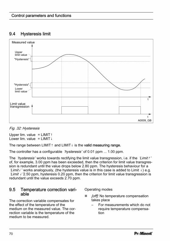
Fig. 32: HysteresisUpper lim. value = LIMIT↑Lower lim. value = LIMIT↓
The range between LIMIT↑ and LIMIT↓ is the valid measuring range.
The controller has a configurable ‘hysteresis’ of 0.01 ppm ... 1.00 ppm.
The ‘hysteresis’ works towards rectifying the limit value transgression, i.e. if the ‘Limit↑’of, for example, 3.00 ppm has been exceeded, then the criterion for limit value transgres‐sion is redundant until the value drops below 2.80 ppm. The hysteresis behaviour for a‘Limit↓’ works analogously, (the hysteresis value is in this case is added to Limit ↓) e.g.‘Limit ↓’ 2.50 ppm, hysteresis 0.20 ppm, then the criterion for limit value transgression isredundant until the value exceeds 2.70 ppm.
9.5 Temperature correction vari‐able
The correction variable compensates forthe effect of the temperature of themedium on the measured value. The cor‐rection variable is the temperature of themedium to be measured.
Operating modes
n [off]: No temperature compensationtakes place– For measurements which do not
require temperature compensa‐tion
Control parameters and functions
70
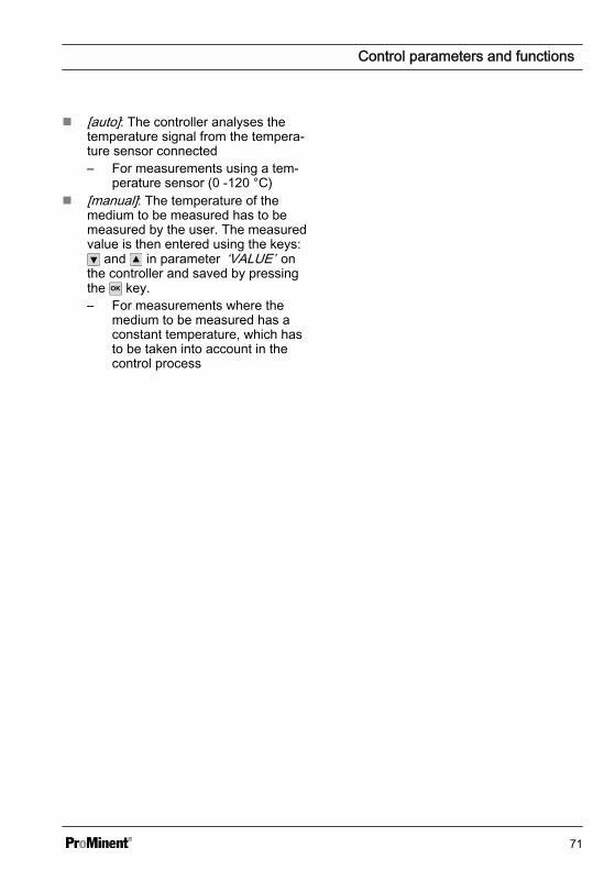
n [auto]: The controller analyses thetemperature signal from the tempera‐ture sensor connected– For measurements using a tem‐
perature sensor (0 -120 °C)n [manual]: The temperature of the
medium to be measured has to bemeasured by the user. The measuredvalue is then entered using the keys:
and in parameter ‘VALUE’ onthe controller and saved by pressingthe key.– For measurements where the
medium to be measured has aconstant temperature, which hasto be taken into account in thecontrol process
Control parameters and functions
71
9.6 Checkout time for measured variable and correction variable
Error text Description
LIMIT ERR Checkout time of the measured variable
TLIMITERR Checkout time of the correction variable
If upon the expiry of the checkout time, the valid measuring range is not reached, thenthe DULCOMETER® Compact Controller exhibits the following behaviour:
n LIMIT ERR: The control is switched off. An error current is emitted, provided theoutput is configured as a measured variable output
n TLIMITERR: The control is switched off. An error current is emitted, provided theoutput is configured as a correction variable output or a measured variable output
Initially the transgression of a limit is only a limit value transgression. This leads to a‘WARNING’ . Switching on the control time ‘TIMELIM’ (> 0 minutes), creates an alarmfrom the limit value transgression. In the event of a [TLIMITERR] a, the control switchesto [STOP].
9.7 Checkout time control
Monitoring of the control pathThe checkout time monitors thecontrol path. The checkout timemechanism permits detection ofpossible defective sensors.
Dead time determination
Each control path has a dead time. Thedead time is the time, which the controlpath requires to detect a change or addi‐tion of metered chemicals using its owninstrumentation.
You must select the checkout time so thatit is greater than the dead time. You candetermine the dead time, by operating themetering pump in manual mode and, forexample, dosing acid.
NOTICE!
Dead time determinationYou should only determine thedead time if the current processcannot be negatively influenced bythe manual metering.
You must determine the time, which thecontrol path (i.e. the entirety of controllers,sensors, measurement water, flowgauges, etc.) requires to detect a firstchange in the measured value startingfrom the beginning of dosing. This time isthe ‘dead time’ . A safety margin, e.g.25%, must be added to this dead time.You must allocate an appropriate safetymargin for your own particular process.
Control parameters and functions
72
The parameter ‘LIMIT’ can be used to seta limit for the control variable. If the con‐trol variable exceeds this limit value, theCHECKTIME fault is triggered (checkouttime of the control has elapsed). The con‐trol is switched to basic load and a faultcurrent output.
9.8 Power relay "P-REL" as limitvalue relay
The power relay ‘P-REL’ can be config‐ured as a limit value relay. It always actonly on the measurement variable,whereby the limits are set in ‘LIMITS’ .The relay is activated upon infringementof either the top or lower limit values.
Constant checking is carried out to deter‐mine whether a limit has been infringedand if this is interrupted with the powerrelay configured ‘P-REL= limit’ for at least‘DELAY ON’ seconds, then the relay isactivated. If the limit value transgressiondisappears for at least ‘DELAY OFF’ sec‐onds, then the limit value relay is againdeactivated.
The limit value relay is deactivated imme‐diately upon: ‘STOP’ , user calibration,‘PAUSE’ and ‘HOLD’ .
Control parameters and functions
73
9.9 Setting and functional description of "Relay Used as a SolenoidValve"
Cyclemin. timeSolenoid
valve
off
on
t
ton
off
on
t
ton
Cycle
Actuatingvariable: 50 %ton
Cycle= 0.50
Actuatingvariable: 80 %ton
Cycle= 0.80
A0025_GB
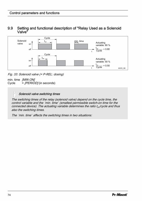
Fig. 33: Solenoid valve (= P-REL: dosing)min. time [MIN ON]Cycle = [PERIOD] (in seconds)
Solenoid valve switching timesThe switching times of the relay (solenoid valve) depend on the cycle time, thecontrol variable and the ‘min. time’ (smallest permissible switch-on time for theconnected device). The actuating variable determines the ratio ton/cycle and thusalso the switching times.The ‘min. time’ affects the switching times in two situations:
Control parameters and functions
74
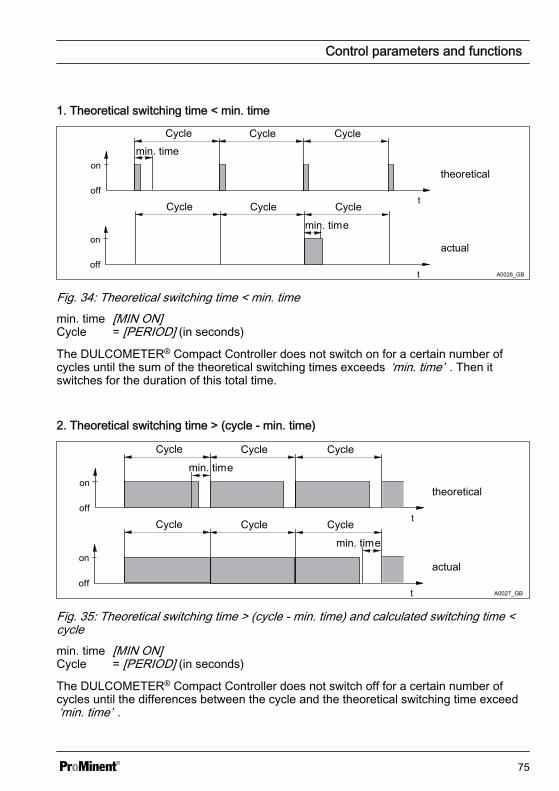
1. Theoretical switching time < min. time
off
on
t
off
on
t
Cycle Cycle Cycle
Cycle Cycle Cycle
min. time
min. time
theoretical
actual
A0026_GB
Fig. 34: Theoretical switching time < min. timemin. time [MIN ON]Cycle = [PERIOD] (in seconds)
The DULCOMETER® Compact Controller does not switch on for a certain number ofcycles until the sum of the theoretical switching times exceeds ‘min. time’ . Then itswitches for the duration of this total time.
2. Theoretical switching time > (cycle - min. time)
Cycle
min. time
off
on
t
off
on
t
Cycle Cycle
Cycle Cycle Cycle
min. time
theoretical
actual
A0027_GB
Fig. 35: Theoretical switching time > (cycle - min. time) and calculated switching time <cyclemin. time [MIN ON]Cycle = [PERIOD] (in seconds)
The DULCOMETER® Compact Controller does not switch off for a certain number ofcycles until the differences between the cycle and the theoretical switching time exceed‘min. time’ .
Control parameters and functions
75
9.10 Alarm relayThe alarm relay triggers in ‘OPERATION’(normal mode) if an error occurs whichhas been defined as ‘ERROR’ and notjust as ‘WARNING’ .The error message ‘ALARM’ in the con‐tinuous display is marked with a ✱ (star)and can be acknowledged with the key.The alarm and the ✱ will then disappear.
9.11 "Error logger" operatingmode
The last three errors are displayed. Alsodisplayed is how long ago (in minutes)they occurred. When a new fault occurs,the oldest fault is deleted.
Faults are only shown which occur inoperating status ‘OPERATION’ , i.e. not inoperating status ‘STOP’ , ‘CAL’ (user cali‐bration), ‘HOLD’ or ‘ PAUSE’ .Only ‘ERRORs’ are shown, not‘WARNINGS’ , e.g. a ‘LIMIT ERR’ isshown, but not ‘ LIMIT↑’ .A fault, whose display has lasted for 999minutes is automatically deleted from the‘Error Logger’ . The ‘Error Logger’ is nei‐ther saved nor backed up in the event ofpower loss.
Control parameters and functions
76
10 Maintenancen User qualification: trained user, see
Ä Chapter 2.2 ‘Users' qualifications’on page 10
The controller is maintenance free.
10.1 Changing the fuse,DULCOMETER® Com‐pact Controller
WARNING!
Danger from electrical voltagePossible consequence: Fatal orvery serious injuries.
– The DULCOMETER® CompactController does not have amains switch
– When working inside the con‐trol unit, disconnect the controlunit from the mains power viaan external switch or byremoving the external fuse
NOTICE!
Use only 5 x 20 mm micro-fusesPossible consequence: Damage tothe product or its surroundings
– 5x20 T 0.315 A– Part number 732404
Fuse change
The mains fuse is located in a sealed fuseholder in the inside of the device.
1. Disconnect the controller from themains power
2. Open the controller and fold thecontroller housing top section to theleft
3. Remove the PCB cover
4. Remove the micro-fuse using asuitable tool
5. Fit the micro-fuse using a suitabletool
6. Refit the PCB cover
7. Replace controller housing top sec‐tion and close the controller
Maintenance
77
10.2 Error messagesn User qualification for diagnosis: trained user, see Ä Chapter 2.2 ‘Users' qualifica‐
tions’ on page 10. Further qualifications depend on the type and scope of possibletroubleshooting measures to be carried out.
Error display delayVarious errors are only displayed after approx. 10 seconds after switching on thecontroller.
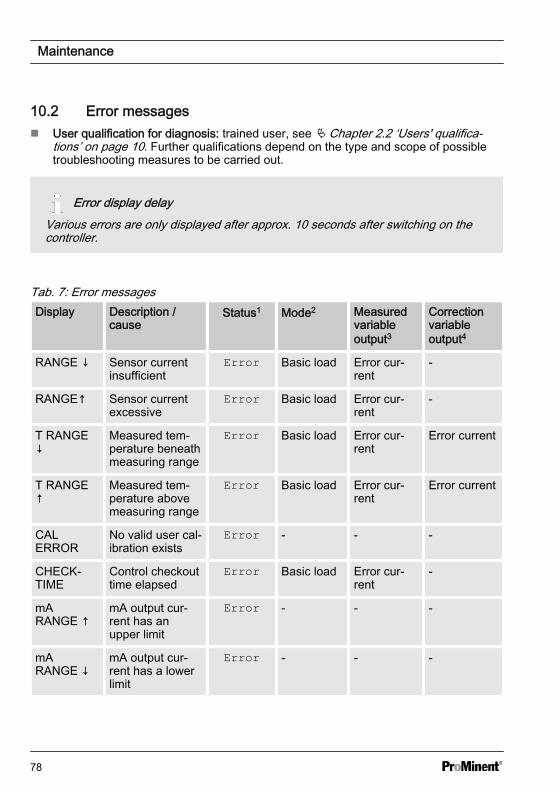
Tab. 7: Error messagesDisplay Description /
causeStatus1 Mode2 Measured
variableoutput3
Correctionvariableoutput4
RANGE ↓ Sensor currentinsufficient
Error Basic load Error cur‐rent
-
RANGE↑ Sensor currentexcessive
Error Basic load Error cur‐rent
-
T RANGE↓
Measured tem‐perature beneathmeasuring range
Error Basic load Error cur‐rent
Error current
T RANGE↑
Measured tem‐perature abovemeasuring range
Error Basic load Error cur‐rent
Error current
CALERROR
No valid user cal‐ibration exists
Error - - -
CHECK‐TIME
Control checkouttime elapsed
Error Basic load Error cur‐rent
-
mARANGE ↑
mA output cur‐rent has anupper limit
Error - - -
mARANGE ↓
mA output cur‐rent has a lowerlimit
Error - - -
Maintenance
78
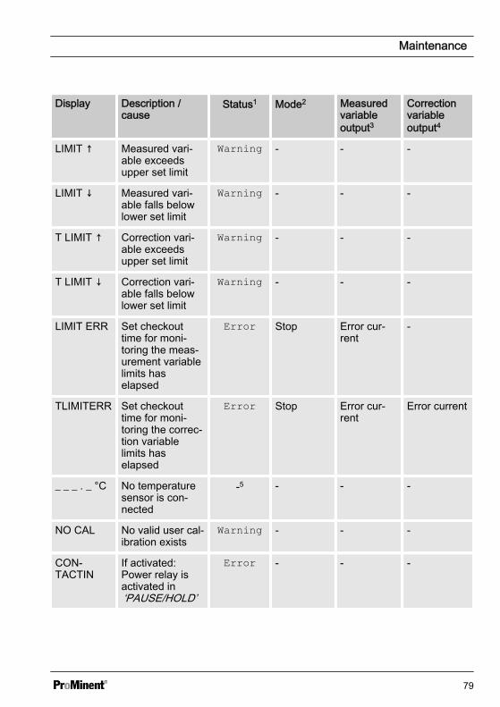
Display Description /cause
Status1 Mode2 Measuredvariableoutput3
Correctionvariableoutput4
LIMIT ↑ Measured vari‐able exceedsupper set limit
Warning - - -
LIMIT ↓ Measured vari‐able falls belowlower set limit
Warning - - -
T LIMIT ↑ Correction vari‐able exceedsupper set limit
Warning - - -
T LIMIT ↓ Correction vari‐able falls belowlower set limit
Warning - - -
LIMIT ERR Set checkouttime for moni‐toring the meas‐urement variablelimits haselapsed
Error Stop Error cur‐rent
-
TLIMITERR Set checkouttime for moni‐toring the correc‐tion variablelimits haselapsed
Error Stop Error cur‐rent
Error current
_ _ _ . _ °C No temperaturesensor is con‐nected
-5 - - -
NO CAL No valid user cal‐ibration exists
Warning - - -
CON‐TACTIN
If activated:Power relay isactivated in‘PAUSE/HOLD’
Error - - -
Maintenance
79
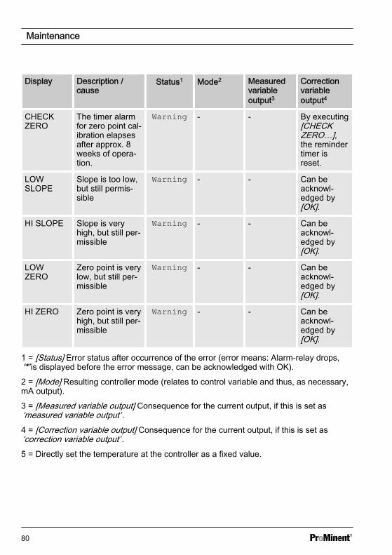
Display Description /cause
Status1 Mode2 Measuredvariableoutput3
Correctionvariableoutput4
CHECKZERO
The timer alarmfor zero point cal‐ibration elapsesafter approx. 8weeks of opera‐tion.
Warning - - By executing[CHECKZERO…],the remindertimer isreset.
LOWSLOPE
Slope is too low,but still permis‐sible
Warning - - Can beacknowl‐edged by[OK].
HI SLOPE Slope is veryhigh, but still per‐missible
Warning - - Can beacknowl‐edged by[OK].
LOWZERO
Zero point is verylow, but still per‐missible
Warning - - Can beacknowl‐edged by[OK].
HI ZERO Zero point is veryhigh, but still per‐missible
Warning - - Can beacknowl‐edged by[OK].
1 = [Status] Error status after occurrence of the error (error means: Alarm-relay drops,‘*’ is displayed before the error message, can be acknowledged with OK).
2 = [Mode] Resulting controller mode (relates to control variable and thus, as necessary,mA output).
3 = [Measured variable output] Consequence for the current output, if this is set as‘measured variable output’ .4 = [Correction variable output] Consequence for the current output, if this is set as‘correction variable output’ .5 = Directly set the temperature at the controller as a fixed value.
Maintenance
80
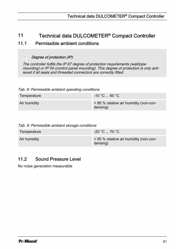
11 Technical data DULCOMETER® Compact Controller11.1 Permissible ambient conditions
Degree of protection (IP)The controller fulfils the IP 67 degree of protection requirements (wall/pipemounting) or IP 54 (control panel mounting). This degree of protection is only ach‐ieved if all seals and threaded connectors are correctly fitted.
Tab. 8: Permissible ambient operating conditionsTemperature -10 °C ... 60 °C
Air humidity < 95 % relative air humidity (non-con‐densing)
Tab. 9: Permissible ambient storage conditionsTemperature -20 °C ... 70 °C
Air humidity < 95 % relative air humidity (non-con‐densing)
11.2 Sound Pressure LevelNo noise generation measurable
Technical data DULCOMETER® Compact Controller
81
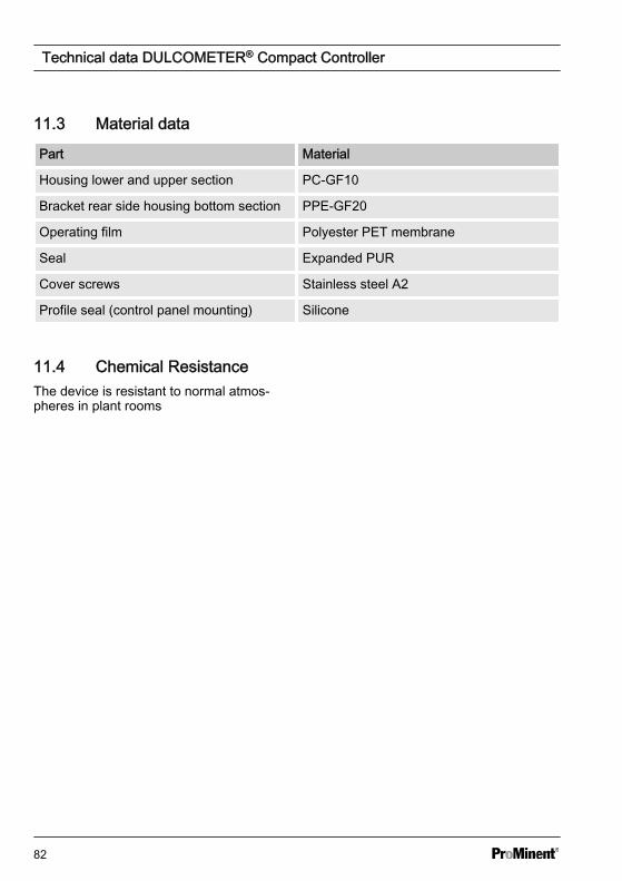
11.3 Material data
Part Material
Housing lower and upper section PC-GF10
Bracket rear side housing bottom section PPE-GF20
Operating film Polyester PET membrane
Seal Expanded PUR
Cover screws Stainless steel A2
Profile seal (control panel mounting) Silicone
11.4 Chemical ResistanceThe device is resistant to normal atmos‐pheres in plant rooms
Technical data DULCOMETER® Compact Controller
82
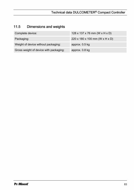
11.5 Dimensions and weights
Complete device: 128 x 137 x 76 mm (W x H x D)
Packaging: 220 x 180 x 100 mm (W x H x D)
Weight of device without packaging: approx. 0.5 kg
Gross weight of device with packaging: approx. 0.8 kg
Technical data DULCOMETER® Compact Controller
83
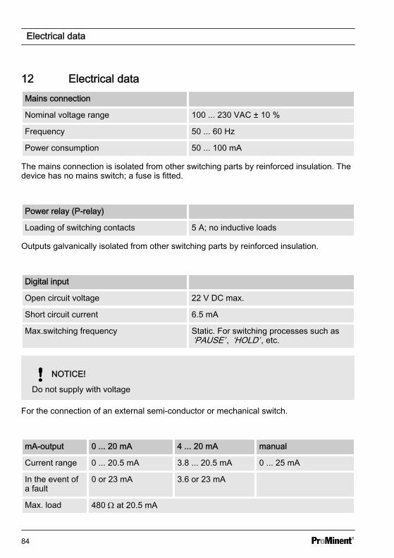
12 Electrical dataMains connection
Nominal voltage range 100 ... 230 VAC ± 10 %
Frequency 50 ... 60 Hz
Power consumption 50 ... 100 mA
The mains connection is isolated from other switching parts by reinforced insulation. Thedevice has no mains switch; a fuse is fitted.
Power relay (P-relay)
Loading of switching contacts 5 A; no inductive loads
Outputs galvanically isolated from other switching parts by reinforced insulation.
Digital input
Open circuit voltage 22 V DC max.
Short circuit current 6.5 mA
Max.switching frequency Static. For switching processes such as‘PAUSE’ , ‘HOLD’ , etc.
NOTICE!
Do not supply with voltage
For the connection of an external semi-conductor or mechanical switch.
mA-output 0 ... 20 mA 4 ... 20 mA manual
Current range 0 ... 20.5 mA 3.8 ... 20.5 mA 0 ... 25 mA
In the event ofa fault
0 or 23 mA 3.6 or 23 mA
Max. load 480 W at 20.5 mA
Electrical data
84
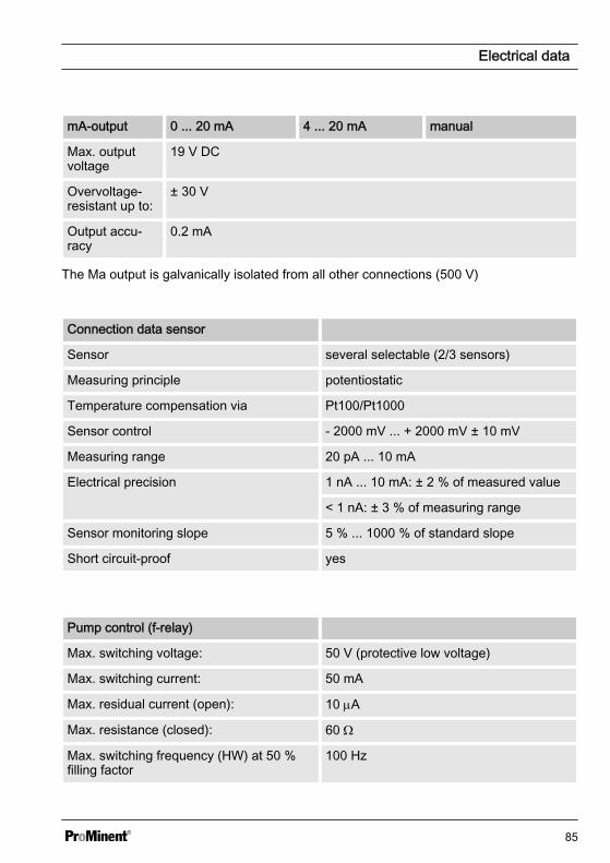
mA-output 0 ... 20 mA 4 ... 20 mA manual
Max. outputvoltage
19 V DC
Overvoltage-resistant up to:
± 30 V
Output accu‐racy
0.2 mA
The Ma output is galvanically isolated from all other connections (500 V)
Connection data sensor
Sensor several selectable (2/3 sensors)
Measuring principle potentiostatic
Temperature compensation via Pt100/Pt1000
Sensor control - 2000 mV ... + 2000 mV ± 10 mV
Measuring range 20 pA ... 10 mA
Electrical precision 1 nA ... 10 mA: ± 2 % of measured value
< 1 nA: ± 3 % of measuring range
Sensor monitoring slope 5 % ... 1000 % of standard slope
Short circuit-proof yes
Pump control (f-relay)
Max. switching voltage: 50 V (protective low voltage)
Max. switching current: 50 mA
Max. residual current (open): 10 mA
Max. resistance (closed): 60 W
Max. switching frequency (HW) at 50 %filling factor
100 Hz
Electrical data
85
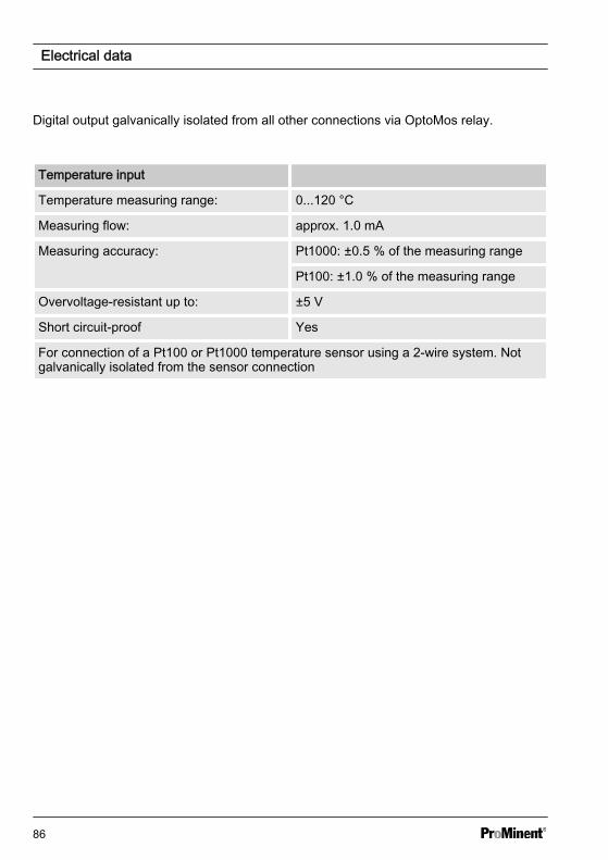
Digital output galvanically isolated from all other connections via OptoMos relay.
Temperature input
Temperature measuring range: 0...120 °C
Measuring flow: approx. 1.0 mA
Measuring accuracy: Pt1000: ±0.5 % of the measuring range
Pt100: ±1.0 % of the measuring range
Overvoltage-resistant up to: ±5 V
Short circuit-proof Yes
For connection of a Pt100 or Pt1000 temperature sensor using a 2-wire system. Notgalvanically isolated from the sensor connection
Electrical data
86
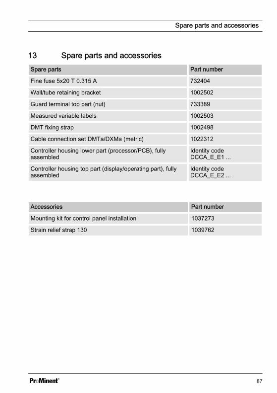
13 Spare parts and accessoriesSpare parts Part number
Fine fuse 5x20 T 0.315 A 732404
Wall/tube retaining bracket 1002502
Guard terminal top part (nut) 733389
Measured variable labels 1002503
DMT fixing strap 1002498
Cable connection set DMTa/DXMa (metric) 1022312
Controller housing lower part (processor/PCB), fullyassembled
Identity codeDCCA_E_E1 ...
Controller housing top part (display/operating part), fullyassembled
Identity codeDCCA_E_E2 ...
Accessories Part number
Mounting kit for control panel installation 1037273
Strain relief strap 130 1039762
Spare parts and accessories
87
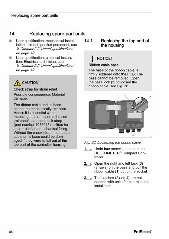
14 Replacing spare part unitsn User qualification, mechanical instal‐
lation: trained qualified personnel, seeÄ Chapter 2.2 ‘Users' qualifications’on page 10
n User qualification, electrical installa‐tion: Electrical technician, seeÄ Chapter 2.2 ‘Users' qualifications’on page 10
CAUTION!
Check strap for strain reliefPossible consequence: Materialdamage.
The ribbon cable and its basecannot be mechanically stressed.Hence it is essential whenmounting the controller in the con‐trol panel, that the check strap(part number 1035918) is fitted forstrain relief and mechanical fixing.Without the check strap, the ribboncable or its base could be dam‐aged if they were to fall out of thetop part of the controller housing.
14.1 Replacing the top part ofthe housing
NOTICE!
Ribbon cable baseThe base of the ribbon cable isfirmly soldered onto the PCB. Thebase cannot be removed. Openthe base lock (3) to loosen theribbon cable, see Fig. 36
1. 2. 3.
4.
Fig. 36: Loosening the ribbon cable1. Undo four screws and open the
DULCOMETER® Compact Con‐troller
2. Open the right and left lock (3)(arrows) on the base and pull theribbon cable (1) out of the socket
3. The catches (2 and 4) are notneeded with units for control panelinstallation.
Replacing spare part units
88
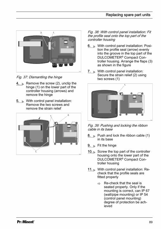
1.2.
Fig. 37: Dismantling the hinge4. Remove the screw (2), unclip the
hinge (1) on the lower part of thecontroller housing (arrows) andremove the hinge
5. With control panel installation:Remove the two screws andremove the strain relief
A0351
1.
2.1.
Fig. 38: With control panel installation: Fitthe profile seal onto the top part of thecontroller housing6. With control panel installation: Posi‐
tion the profile seal (arrow) evenlyinto the groove in the top part of theDULCOMETER® Compact Con‐troller housing. Arrange the flaps (3)as shown in the figure
7. With control panel installation:Secure the strain relief (2) usingtwo screws (1)
A0352
1.
Fig. 39: Pushing and locking the ribboncable in its base8. Push and lock the ribbon cable (1)
in its base
9. Fit the hinge
10. Screw the top part of the controllerhousing onto the lower part of theDULCOMETER® Compact Con‐troller housing
11. With control panel installation: Re-check that the profile seals arefitted properly
ð Re-check that the seal isseated properly. Only if themounting is correct, can IP 67(wall/pipe mounting) or IP 54(control panel mounting)degree of protection be ach‐ieved
Replacing spare part units
89
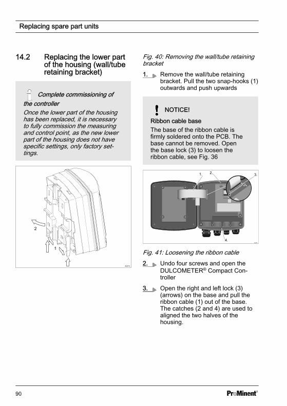
14.2 Replacing the lower partof the housing (wall/tuberetaining bracket)
Complete commissioning ofthe controllerOnce the lower part of the housinghas been replaced, it is necessaryto fully commission the measuringand control point, as the new lowerpart of the housing does not havespecific settings, only factory set‐tings.
2
1
A0273
Fig. 40: Removing the wall/tube retainingbracket1. Remove the wall/tube retaining
bracket. Pull the two snap-hooks (1)outwards and push upwards
NOTICE!
Ribbon cable baseThe base of the ribbon cable isfirmly soldered onto the PCB. Thebase cannot be removed. Openthe base lock (3) to loosen theribbon cable, see Fig. 36
1. 2. 3.
4.
Fig. 41: Loosening the ribbon cable2. Undo four screws and open the
DULCOMETER® Compact Con‐troller
3. Open the right and left lock (3)(arrows) on the base and pull theribbon cable (1) out of the base.The catches (2 and 4) are used toaligned the two halves of thehousing.
Replacing spare part units
90
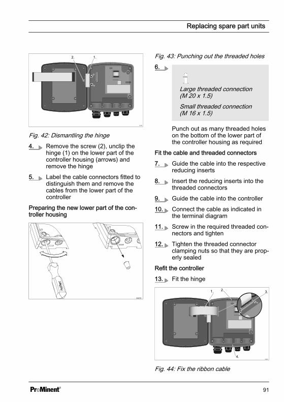
1.2.
Fig. 42: Dismantling the hinge4. Remove the screw (2), unclip the
hinge (1) on the lower part of thecontroller housing (arrows) andremove the hinge
5. Label the cable connectors fitted todistinguish them and remove thecables from the lower part of thecontroller
Preparing the new lower part of the con‐troller housing
A0272
Fig. 43: Punching out the threaded holes6.
Large threaded connection(M 20 x 1.5)Small threaded connection(M 16 x 1.5)
Punch out as many threaded holeson the bottom of the lower part ofthe controller housing as required
Fit the cable and threaded connectors
7. Guide the cable into the respectivereducing inserts
8. Insert the reducing inserts into thethreaded connectors
9. Guide the cable into the controller
10. Connect the cable as indicated inthe terminal diagram
11. Screw in the required threaded con‐nectors and tighten
12. Tighten the threaded connectorclamping nuts so that they are prop‐erly sealed
Refit the controller
13. Fit the hinge
1. 2. 3.
4.
Fig. 44: Fix the ribbon cable
Replacing spare part units
91
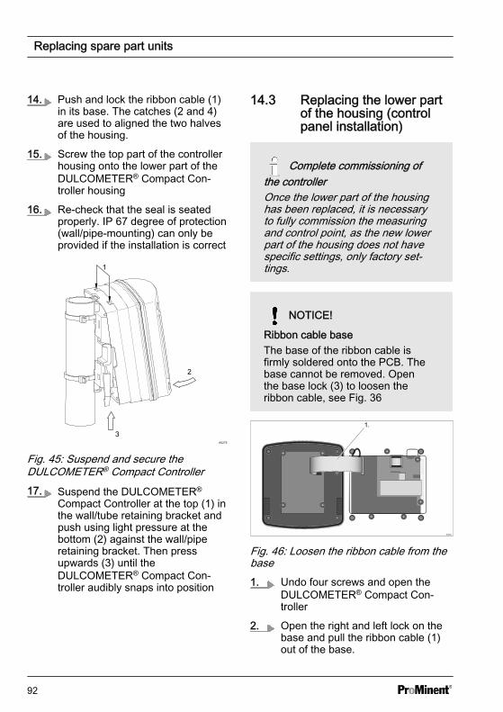
14. Push and lock the ribbon cable (1)in its base. The catches (2 and 4)are used to aligned the two halvesof the housing.
15. Screw the top part of the controllerhousing onto the lower part of theDULCOMETER® Compact Con‐troller housing
16. Re-check that the seal is seatedproperly. IP 67 degree of protection(wall/pipe-mounting) can only beprovided if the installation is correct
A0275
3
2
1
Fig. 45: Suspend and secure theDULCOMETER® Compact Controller17. Suspend the DULCOMETER®
Compact Controller at the top (1) inthe wall/tube retaining bracket andpush using light pressure at thebottom (2) against the wall/piperetaining bracket. Then pressupwards (3) until theDULCOMETER® Compact Con‐troller audibly snaps into position
14.3 Replacing the lower partof the housing (controlpanel installation)
Complete commissioning ofthe controllerOnce the lower part of the housinghas been replaced, it is necessaryto fully commission the measuringand control point, as the new lowerpart of the housing does not havespecific settings, only factory set‐tings.
NOTICE!
Ribbon cable baseThe base of the ribbon cable isfirmly soldered onto the PCB. Thebase cannot be removed. Openthe base lock (3) to loosen theribbon cable, see Fig. 36
A0352
1.
Fig. 46: Loosen the ribbon cable from thebase1. Undo four screws and open the
DULCOMETER® Compact Con‐troller
2. Open the right and left lock on thebase and pull the ribbon cable (1)out of the base.
Replacing spare part units
92
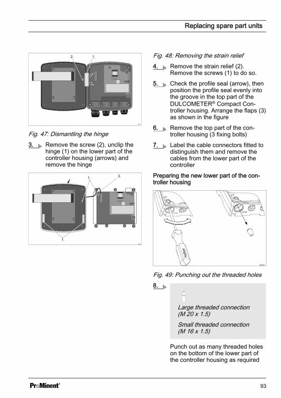
1.2.
Fig. 47: Dismantling the hinge3. Remove the screw (2), unclip the
hinge (1) on the lower part of thecontroller housing (arrows) andremove the hinge
A0351
1.
2.1.
Fig. 48: Removing the strain relief4. Remove the strain relief (2).
Remove the screws (1) to do so.
5. Check the profile seal (arrow), thenposition the profile seal evenly intothe groove in the top part of theDULCOMETER® Compact Con‐troller housing. Arrange the flaps (3)as shown in the figure
6. Remove the top part of the con‐troller housing (3 fixing bolts)
7. Label the cable connectors fitted todistinguish them and remove thecables from the lower part of thecontroller
Preparing the new lower part of the con‐troller housing
A0272
Fig. 49: Punching out the threaded holes8.
Large threaded connection(M 20 x 1.5)Small threaded connection(M 16 x 1.5)
Punch out as many threaded holeson the bottom of the lower part ofthe controller housing as required
Replacing spare part units
93
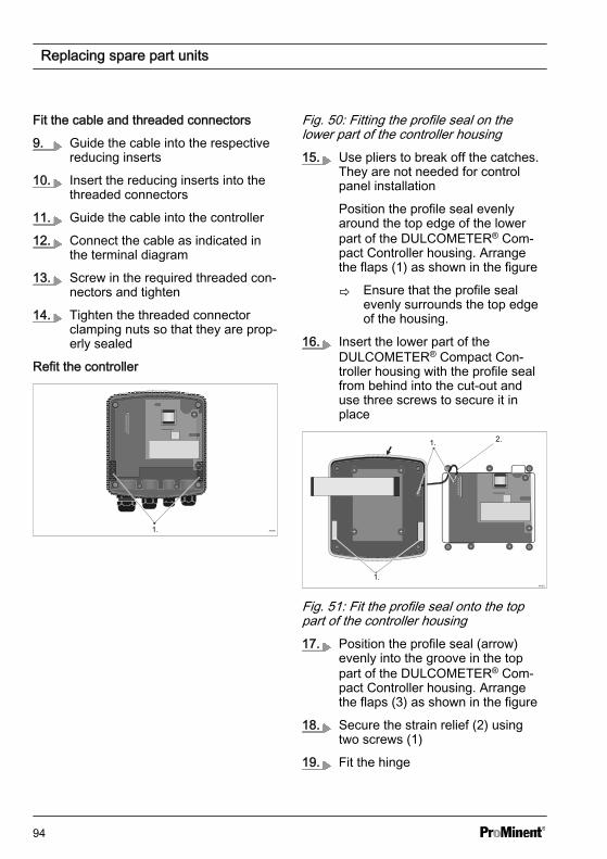
Fit the cable and threaded connectors
9. Guide the cable into the respectivereducing inserts
10. Insert the reducing inserts into thethreaded connectors
11. Guide the cable into the controller
12. Connect the cable as indicated inthe terminal diagram
13. Screw in the required threaded con‐nectors and tighten
14. Tighten the threaded connectorclamping nuts so that they are prop‐erly sealed
Refit the controller
A03601.
Fig. 50: Fitting the profile seal on thelower part of the controller housing15. Use pliers to break off the catches.
They are not needed for controlpanel installation
Position the profile seal evenlyaround the top edge of the lowerpart of the DULCOMETER® Com‐pact Controller housing. Arrangethe flaps (1) as shown in the figure
ð Ensure that the profile sealevenly surrounds the top edgeof the housing.
16. Insert the lower part of theDULCOMETER® Compact Con‐troller housing with the profile sealfrom behind into the cut-out anduse three screws to secure it inplace
A0351
1.
2.1.
Fig. 51: Fit the profile seal onto the toppart of the controller housing17. Position the profile seal (arrow)
evenly into the groove in the toppart of the DULCOMETER® Com‐pact Controller housing. Arrangethe flaps (3) as shown in the figure
18. Secure the strain relief (2) usingtwo screws (1)
19. Fit the hinge
Replacing spare part units
94
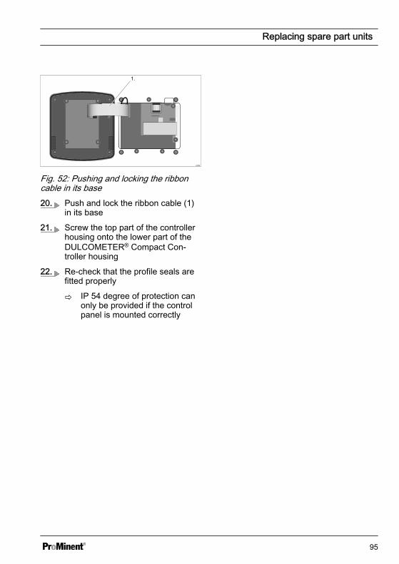
A0352
1.
Fig. 52: Pushing and locking the ribboncable in its base20. Push and lock the ribbon cable (1)
in its base
21. Screw the top part of the controllerhousing onto the lower part of theDULCOMETER® Compact Con‐troller housing
22. Re-check that the profile seals arefitted properly
ð IP 54 degree of protection canonly be provided if the controlpanel is mounted correctly
Replacing spare part units
95
15 Standards complied with and Declaration of ConformityThe EC Declaration of Conformity for thecontroller is available to download on ourhomepage.
EN 60529 Specification for degrees ofprotection provided by housings (IP code)
EN 61000 Electromagnetic Compatibility(EMC)
EN 61010 Safety requirements for elec‐trical equipment for measurement, controland laboratory use - Part 1: Generalrequirements
EN 61326 Electrical equipment for meas‐uring, control and laboratory use - EMCrequirements (for class A and B devices)
Standards complied with and Declaration of Conformity
96
16 Disposal of Used Partsn User qualification: instructed user,
see Ä Chapter 2.2 ‘Users' qualifica‐tions’ on page 10
NOTICE!
Regulations governing the disposalof used parts– Note the current national regu‐
lations and legal standardswhich apply in your country
The manufacturer will take back decon‐taminated used units providing they arecovered by adequate postage.
Decontaminate the unit before returning itfor repair. To do so, remove all traces ofhazardous substances. Refer to the Mate‐rial Safety Data Sheet for your feed chem‐ical.
A current Declaration of Decontaminationis available to download on the ProMinentwebsite.
Disposal of Used Parts
97
17 IndexAAccessories . . . . . . . . . . . . . . . . . . . 87Action, step by step . . . . . . . . . . . . . . 2Ambient conditions . . . . . . . . . . . . . . 81
BBasic functions . . . . . . . . . . . . . . . . 15Bottom section of the control housing 26
CCable connection set . . . . . . . . . . . . 20Cable ties . . . . . . . . . . . . . . . . . . . . 22Check strap for strain relief . . . . . . . . 88Chemical Resistance . . . . . . . . . . . . 82Configuration . . . . . . . . . . . . . . . . . . 15Contrast setting . . . . . . . . . . . . . . . . 43Control elements . . . . . . . . . . . . . . . 42Control panel cut-out . . . . . . . . . . 24, 26
DDeburr the edges . . . . . . . . . . . . . . . 24Declaration of Conformity . . . . . . . . . 96Degree of protection IP 54 . . . . . . 26, 38Degree of protection IP 67 . . . . . . . . 38Dimensions . . . . . . . . . . . . . . . . . . . 83Drill . . . . . . . . . . . . . . . . . . . . . . . . 24Drill holes . . . . . . . . . . . . . . . . . . . . 21Drilling template . . . . . . . . . . . . . . . . 24
EError Logger . . . . . . . . . . . . . . . . . . 76
FFine fuse 5x20 T 0.315 A . . . . . . . . . 87
GGeneral non-discriminatory approach . . 2
HHysteresis . . . . . . . . . . . . . . . . . . . . 54
IIdentity code . . . . . . . . . . . . . . . . . . . 6Incorrect metering . . . . . . . . . . . . . . 41Interference-prone cables . . . . . . . . . 31
LLarge threaded connection (M 20 x1.5) . . . . . . . . . . . . . . . . . . . . . . . . 38Legend to the "Wiring" table . . . . . . . . 36Links to elements or sections of theseinstructions or other applicable docu‐ments . . . . . . . . . . . . . . . . . . . . . . . . 2
MMaterial thickness of control panel . . . 23Max. switching current: . . . . . . . . . . 85Max. switching voltage: . . . . . . . . . . . 85More symbols . . . . . . . . . . . . . . . . . . 2Mounting (mechanical) . . . . . . . . . . . 20Mounting kit . . . . . . . . . . . . . . . . . . . 23Mounting materials . . . . . . . . . . . . . . 20Mounting position . . . . . . . . . . . . . . . 19
Index
98
NNoise generation . . . . . . . . . . . . . . . 81Non-discriminatory approach . . . . . . . . 2
OOriginal Prominent cable . . . . . . . . . . 34Overview of equipment . . . . . . . . . . 42
PPipe bracket . . . . . . . . . . . . . . . . . . 21Pipe diameter . . . . . . . . . . . . . . . . . 22plant rooms . . . . . . . . . . . . . . . . . . . 82Preparing the control panel . . . . . . . . 24Profile seal . . . . . . . . . . . . . . . . . . . 26Punch out threaded holes . . . . . . . . . 38
QQuestion: Does the system have tem‐perature compensation? . . . . . . . . . . 70Question: How are the menus to beaccessed? . . . . . . . . . . . . . . . . . . . . 16Question: How do I calibrate a newsensor? . . . . . . . . . . . . . . . . . . . . . . 52Question: How do I calibrate thesensor zero point? . . . . . . . . . . . . . . 51Question: How is initial commis‐sioning undertaken? . . . . . . . . . . . . . 41Question: How is the device andsensor calibrated? . . . . . . . . . . . . . . 47Question: How is the sensor cable tobe assembled? . . . . . . . . . . . . . . . . 32Question: In what position should thecontroller be mounted to facilitate itsreading, installation and operation? . . 19
Question: Is there a legend to the"Wiring" table? . . . . . . . . . . . . . . . . . 36Question: Must control be configuredduring commissioning? . . . . . . . . . . . 41Question: What applications areintended for this controller? . . . . . . . . 15Question: What can be calibrated? . . . 47Question: What can the output relaysdo? . . . . . . . . . . . . . . . . . . . . . . . . . 15Question: What control direction isavailable? . . . . . . . . . . . . . . . . . . . . 15Question: What do I have to considerin terms of recycling? . . . . . . . . . . . . 19Question: What do the LEDs indicate? 15Question: What happens in the eventof incorrect calibration? . . . . . . . . . . . 47Question: What information is madeavailable in the continuous display? . . 43Question: What information is madeavailable in the info display? . . . . . . . 44Question: What is the load capacity ofthe hinge? . . . . . . . . . . . . . . . . . . . . 19Question: What needs to be consid‐ered in terms of accessibility? . . . . . . 19Question: When are the actuatorsreset to factory settings? . . . . . . . . . . 41Question: Where can I find the Decla‐ration of Conformity? . . . . . . . . . . . . 96Question: Which cable is connectedto which threaded connector? . . . . . . 33Question: Which measured variablescan be processed? . . . . . . . . . . . . . . 15Question: Which standards are com‐plied with? . . . . . . . . . . . . . . . . . . . . 96
Index
99
RReducing inserts . . . . . . . . . . . . . . . 38Replacing spare part units . . . . . . . . . 88Replacing the lower part of thehousing (control panel installation) . . . 92Replacing the lower part of thehousing (wall/tube retaining bracket) . . 90Replacing the top part of the housing . 88
SSafety information . . . . . . . . . . . . . . . 8Small threaded connection (M 16 x1.5) . . . . . . . . . . . . . . . . . . . . . . . . 38Snap-hooks . . . . . . . . . . . . . . . . . . . 21Sound Pressure Level . . . . . . . . . . . . 81Spare parts . . . . . . . . . . . . . . . . . . . 87Standard scope of delivery . . . . . . . . 20Standards complied with . . . . . . . . . . 96Strain relief . . . . . . . . . . . . . . . . 26, 38
Strain relief strap . . . . . . . . . . . . . . . 87Swimming pool water treatment . . . . . 15
TTerminal diagram . . . . . . . . . . . . . . . 37Top section of the control housing . . . 26Treatment of drinking water . . . . . . . . 15
UUsers' qualifications . . . . . . . . . . . . . 10
VVenting . . . . . . . . . . . . . . . . . . . . . . 69
WWall/pipe bracket . . . . . . . . . . . . . . . 21Washer . . . . . . . . . . . . . . . . . . . . . . 20Weights . . . . . . . . . . . . . . . . . . . . . 83Wiring . . . . . . . . . . . . . . . . . . . . . . . 34
Index
100

101

102

103

985626, 4, en_GB
© 2015
ProMinent GmbHIm Schuhmachergewann 5 - 1169123 Heidelberg, GermanyTelephone: +49 6221 842-0Fax: +49 6221 842-419Email: [email protected]: www.prominent.com
Related Documents