Fan Basics - Fans - Fan Laws - Velocity Profile in Straight Fan Outlet Duct - Do’s and Don’t Duct Basics - What is Duct - Air Distribution System Components - Supply, Return and Fresh Air - Type of Pressure - Static Pressure - Total Pressure - Velocity Pressure - Aspect Ratio - Effect of Aspect Ratio - Advantages and Disadvantages of various Ducts - Velocity in Ducts Duct Design - Duct Sizing Methods - Considerations for Duct Design - Example Problem with Equal Friction Method - Friction Chart - Circular Equivalents of Rectangular Ducts - Friction of Rectangular Elbows - Components of Ducting - Types of Joints - Plenum - Plenum Design - Grilles, Diffusers - Grilles, Diffusers Selection - Turning Vanes, Splitter Vanes - Design of Transition Ducts - Do’s and Don’t of Ducting Appendix - Legend - Recommended GI Sheet Metal Gauge - Friction Chart 22 23 25 28 33 36 38 39 40 41 42 43 44 45 46 55 56 57 3 4 5 6 9 10 11 12 13 14 15 16 17 18 19 Contents Good Installation Excellent Performance 1

DUCT_DESIGN Class Material.pdf
Dec 22, 2015
Welcome message from author
This document is posted to help you gain knowledge. Please leave a comment to let me know what you think about it! Share it to your friends and learn new things together.
Transcript
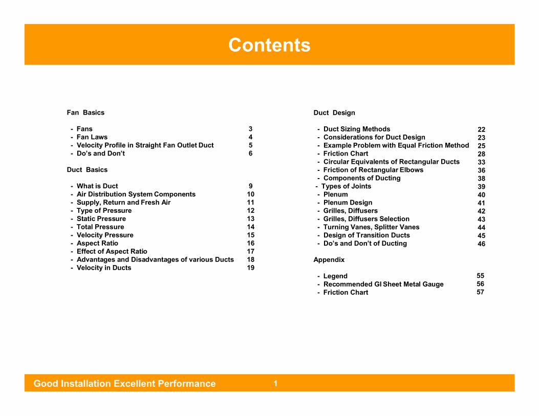
Fan Basics
- Fans- Fan Laws- Velocity Profile in Straight Fan Outlet Duct- Do’s and Don’t
Duct Basics
- What is Duct- Air Distribution System Components- Supply, Return and Fresh Air - Type of Pressure - Static Pressure - Total Pressure - Velocity Pressure - Aspect Ratio - Effect of Aspect Ratio - Advantages and Disadvantages of various Ducts - Velocity in Ducts
Duct Design
- Duct Sizing Methods - Considerations for Duct Design- Example Problem with Equal Friction Method- Friction Chart- Circular Equivalents of Rectangular Ducts- Friction of Rectangular Elbows- Components of Ducting
- Types of Joints- Plenum- Plenum Design- Grilles, Diffusers- Grilles, Diffusers Selection- Turning Vanes, Splitter Vanes- Design of Transition Ducts- Do’s and Don’t of Ducting
Appendix
- Legend- Recommended GI Sheet Metal Gauge- Friction Chart
222325283336383940414243444546
555657
3456
910111213141516171819
Contents
Good Installation Excellent Performance 1

Fan Basics
Good Installation Excellent Performance 2

“A fan is a power driven rotary machine which causes
a continuous flow of air. A fan has rotating bladed
impeller. The blades exert force on the air, raising
its pressure and maintaining a continuous flow.”
A fan may be ‘ directly driven’ or ‘ belt driven ’
Fans
Good Installation Excellent Performance 3

Fan Laws Fan System Curve
Good Installation Excellent Performance 4

Fan Laws Fan Laws
Good Installation Excellent Performance 4

Baffle Plate
Velocity Profile in Straight Fan Outlet Duct
Good Installation Excellent Performance 5
CUT OFF
BLAST AREA
OUTLET AREA
DISCHARGEDUCT
INLETCOLLER
FAN HOUSINGCENTRIFUGAL 100% EFFECTIVE DUCT LENGTH
25%
50%
75%

Fan Efficiency = 1/4 x ( 100% Normal Efficiency )
Fan Efficiency = 1/2 x ( 100% Normal Efficiency )
An upward elbow just after the blower outlet
A downward elbow just after the blower outlet
If D = Blower Diameter
3 x D
First Elbow should be after three times the blower diameter
Good Installation Excellent Performance 6
Do’s and Don’t of Ducting
Don’t Do’s

Does and Don’t of Ducting
IDUNo Beam !!
IDU Duct
Flexible Connection
IDU
IDU Duct
Flexible Connection
Side View
Top View
Side View
Top View
Good Installation Excellent Performance 7
Do’s and Don’t of Ducting
Don’t Do’s

Duct Basics
Good Installation Excellent Performance 8

A Duct can be described as a device used to provide an isolation path to carry an item
from one place to other place without bringing the product in contact with the
atmosphere before the delivery point.
What is a Duct
Good Installation Excellent Performance 9
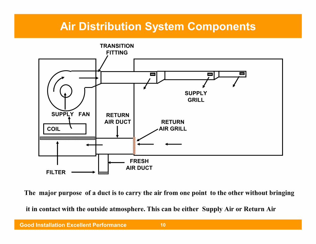
The major purpose of a duct is to carry the air from one point to the other without bringing
it in contact with the outside atmosphere. This can be either Supply Air or Return Air
TRANSITIONFITTING
COIL
RETURN AIR DUCT
SUPPLY FANRETURN
AIR GRILL
FILTER
SUPPLY GRILL
FRESH AIR DUCT
Air Distribution System Components
Good Installation Excellent Performance 10

Supply Air It is defined as the conditioned air being supplied from the air conditioner
outlet. This air is treated air & contains all the desired qualities as provided by the air
conditioning system
Return Air It is defined as the air being supplied back to the air conditioner from the
air conditioned area. This air is returned back to the air conditioner after being circulated in
the conditioned area.
Return air path should be 1.25 to 1.5 times the Supply air path
Fresh Air It is defined as the ambient air being supplied to the air conditioner
inlet from the outside atmosphere. This air is supplied to the air conditioner inlet from the
outside atmosphere after being initially treated.
Supply, Return and Fresh Air
Good Installation Excellent Performance 11
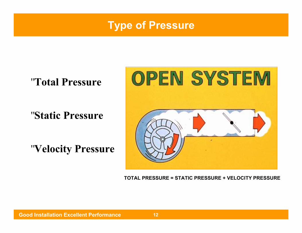
• Total Pressure
• Static Pressure
• Velocity Pressure
Type of Pressure
Good Installation Excellent Performance 12
TOTAL PRESSURE = STATIC PRESSURE + VELOCITY PRESSURE
Type of Pressure
Good Installation Excellent Performance 12
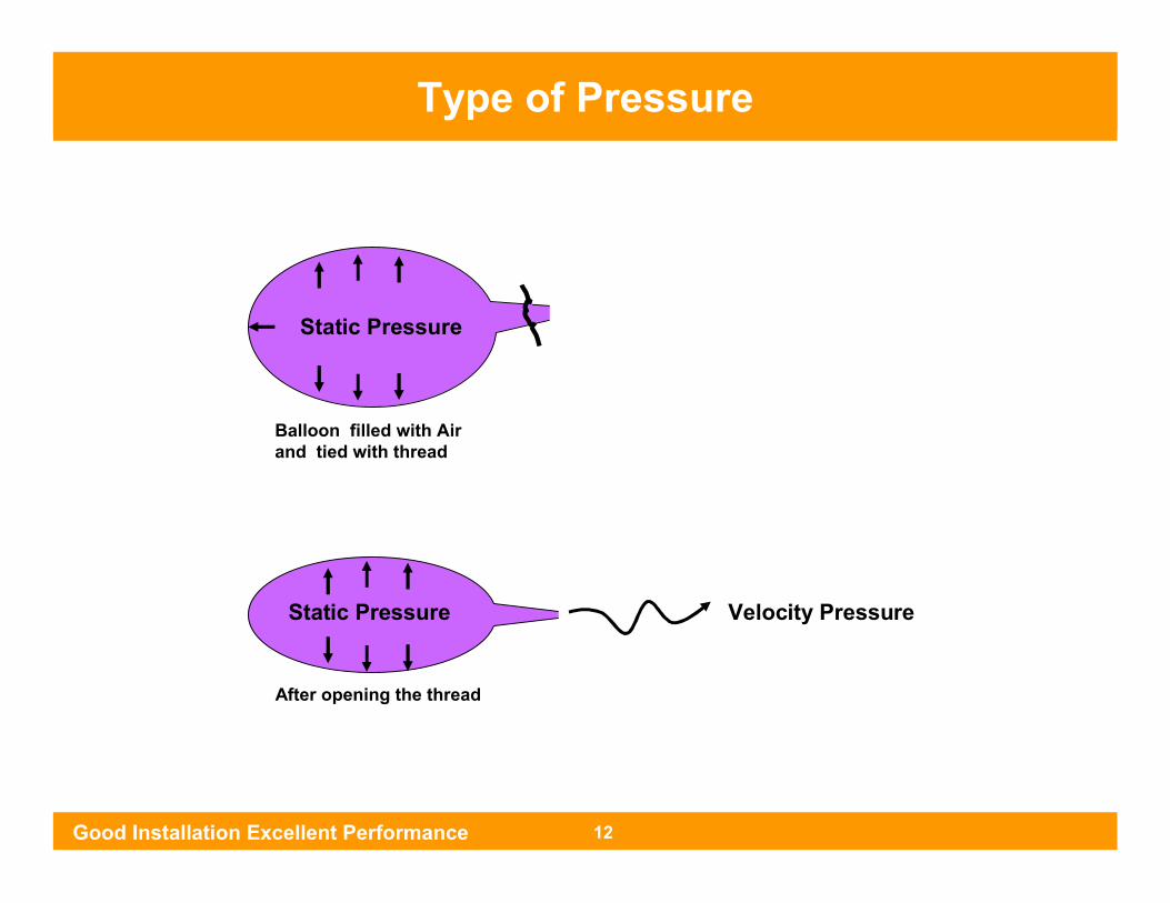
Static Pressure
Static Pressure Velocity Pressure
Balloon filled with Airand tied with thread
After opening the thread

Static Pressure is measured perpendicular to the direction of flow of the air.
May be +ve or -ve
Static Pressure
Good Installation Excellent Performance 13
-ve
+ve
Ps
Ps
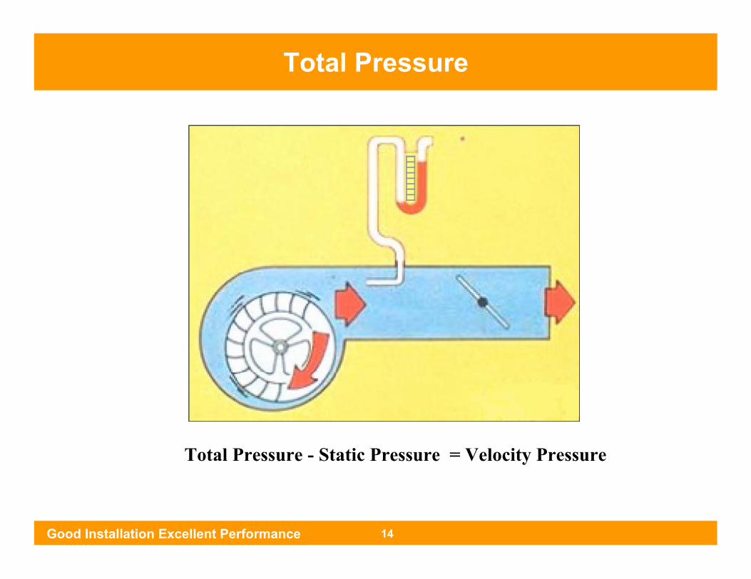
Total Pressure - Static Pressure = Velocity Pressure
Total Pressure
Good Installation Excellent Performance 14
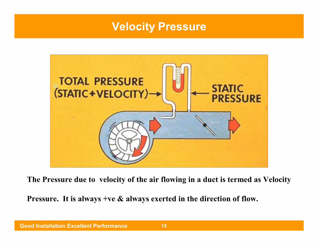
The Pressure due to velocity of the air flowing in a duct is termed as Velocity
Pressure. It is always +ve & always exerted in the direction of flow.
Velocity Pressure
Good Installation Excellent Performance 15

WidthHeight
Aspect Ratio = Long Side / Short Side
= Width of the duct / Height of the duct
Best Aspect Ratio is 1 : 1
Maximum permissible aspect ratio is 4 : 1
Aspect Ratio
Good Installation Excellent Performance 16
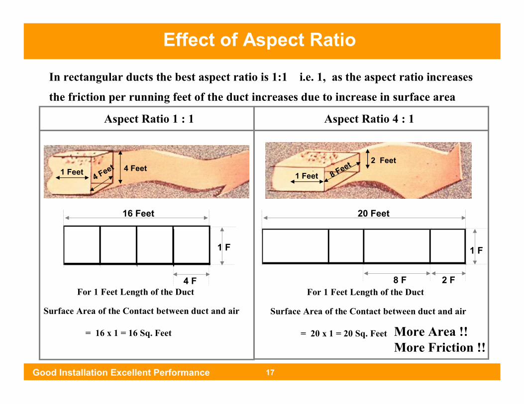
In rectangular ducts the best aspect ratio is 1:1 i.e. 1, as the aspect ratio increases
the friction per running feet of the duct increases due to increase in surface area
Aspect Ratio 1 : 1 Aspect Ratio 4 : 1
8 Feet 2 Feet4 Feet
4 Feet
16 Feet
1 F 1 F
20 Feet
2 F8 FFor 1 Feet Length of the Duct For 1 Feet Length of the Duct
Surface Area of the Contact between duct and air
= 16 x 1 = 16 Sq. Feet
Surface Area of the Contact between duct and air
= 20 x 1 = 20 Sq. Feet More Area !!More Friction !!
1 Feet 1 Feet
4 F
Effect of Aspect Ratio
Good Installation Excellent Performance 17
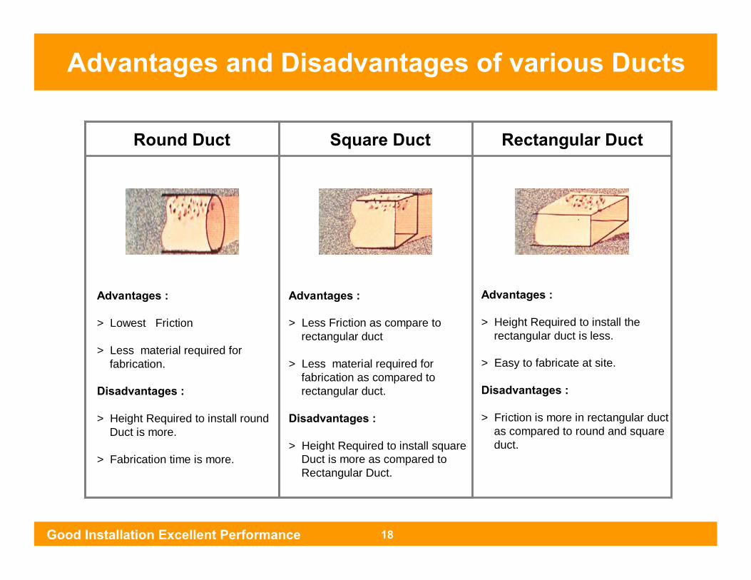
Round Duct Square Duct Rectangular Duct
Advantages :
> Lowest Friction
> Less material required for fabrication.
Disadvantages :
> Height Required to install round Duct is more.
> Fabrication time is more.
Advantages :
> Less Friction as compare to rectangular duct
> Less material required for fabrication as compared to rectangular duct.
Disadvantages :
> Height Required to install square Duct is more as compared to Rectangular Duct.
Advantages :
> Height Required to install the rectangular duct is less.
> Easy to fabricate at site.
Disadvantages :
> Friction is more in rectangular ductas compared to round and square duct.
Good Installation Excellent Performance 18
Advantages and Disadvantages of various Ducts

Supply Air Duct Velocities
Return Air Duct Velocities
Velocity in Ducts
Good Installation Excellent Performance 19
Grill VelocitiesMax. Permissible grill velocity 450 fpm
Application Commercial Comfort Air Conditioning
Low Velocity 800 fpm to 1600 fpmHigh Velocity Above 1800 fpm
Application Commercial Comfort Air Conditioning
Low Velocity 800 fpm to 1600 fpmHigh Velocity Above 1800 fpm
Velocity in Ducts
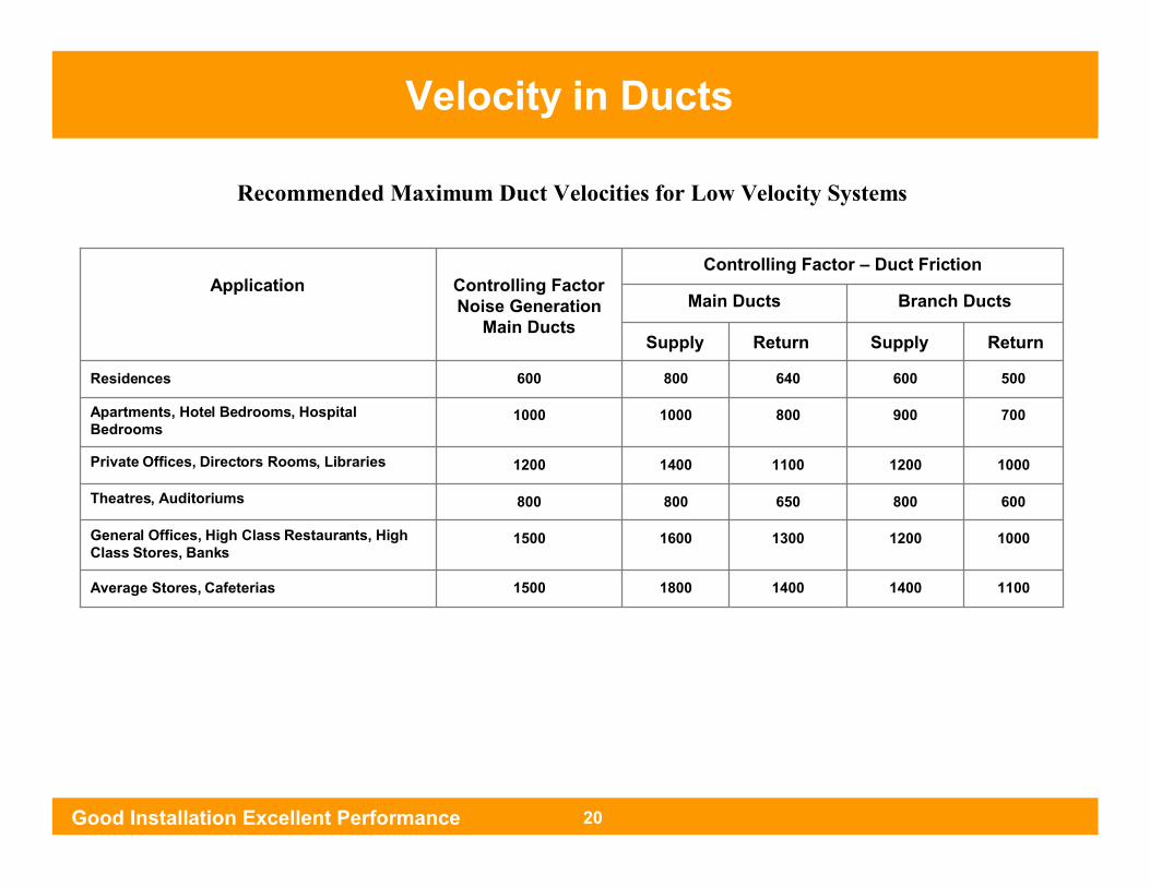
Recommended Maximum Duct Velocities for Low Velocity Systems
Good Installation Excellent Performance 20
Velocity in Ducts
11001400140018001500Average Stores, Cafeterias
10001200130016001500General Offices, High Class Restaurants, HighClass Stores, Banks
600800650800800Theatres, Auditoriums
10001200110014001200Private Offices, Directors Rooms, Libraries
70090080010001000Apartments, Hotel Bedrooms, Hospital Bedrooms
500600640800600Residences
ReturnSupplyReturnSupply
Branch DuctsMain Ducts
Controlling Factor – Duct FrictionControlling Factor Noise Generation
Main Ducts
Application

Duct Design
Good Installation Excellent Performance 21

Duct Sizing Methods
Velocity Reduction Not used as it requires broad background of duct design experience.
Equal Friction(Generally UsedMethod)
In this method ducts are sized for a constant pressure loss per unit length.
For rectangular duct the recommended unit friction rate is 0.08 to 0.1 in. Aq for 100 feet length of the duct. TheMaximum limit is 0.12 in. Aq for 100 feet length of the duct.
Static Regain The objective of static regain method is to obtain the samestatic pressure at diverging flow junctions by changing down stream duct sizes.
Good Installation Excellent Performance 22
Ducts Sizing Methods
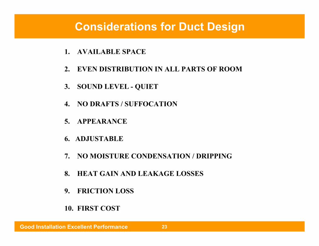
Considerations for Duct Design
1. AVAILABLE SPACE
2. EVEN DISTRIBUTION IN ALL PARTS OF ROOM
3. SOUND LEVEL - QUIET
4. NO DRAFTS / SUFFOCATION
5. APPEARANCE
6. ADJUSTABLE
7. NO MOISTURE CONDENSATION / DRIPPING
8. HEAT GAIN AND LEAKAGE LOSSES
9. FRICTION LOSS
10. FIRST COST
Good Installation Excellent Performance 23
Considerations for Duct Design

Equal Friction Method
Good Installation Excellent Performance 24
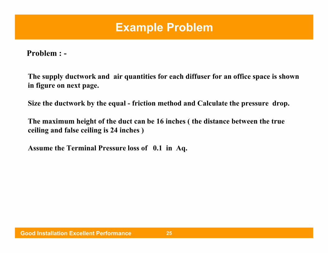
The supply ductwork and air quantities for each diffuser for an office space is shownin figure on next page.
Size the ductwork by the equal - friction method and Calculate the pressure drop.
The maximum height of the duct can be 16 inches ( the distance between the true ceiling and false ceiling is 24 inches )
Assume the Terminal Pressure loss of 0.1 in Aq.
Problem : -
Good Installation Excellent Performance 25
Example Problem

Example Problem
Diffuser with 500 CFM
Diffuser with 400 CFM
Total Air Quantity = 3400 cfm
Assume Initial Velocity = 1300
Friction Rate = 0.1 inch wg per 100 Ft.of equivalent Length
Solution : -
5 Ft.
5 Ft. 3400 CFM
FAN 3400 CFM
5 Ft. 1700 CFM
10 Ft. 1300 CFM
1
2
3
4
A
10 Ft. 900 CFM
10 Ft. 500 CFM
10 Ft. 1700 CFM
10 Ft. 1300 CFM
5
6
7
8
D
10 Ft. 900 CFM
10 Ft. 500 CFM
5 Ft.
B C
Good Installation Excellent Performance 26
Example Problem
Good Installation Excellent Performance 27
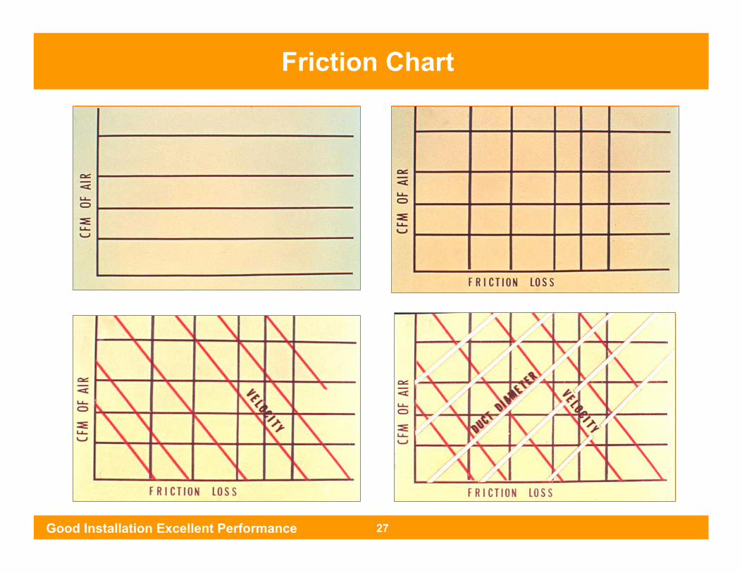
Friction Chart

Friction Chart
FRIC
TION
LOSS FO
R R
OU
ND
DU
CT
AIR QUANTITY (CFM)
AIR QUANTITY (CFM)

Step 1 : Assume Velocity in main section.Step 2 : Find the intersection of Air Flow ( CFM ) and
Velocity Line.
Step 4 : The diameter line passing through the intersection pointgives round duct diameter.
Step 3 : Vertical line from the point of intersection will give the unit friction rate line which is constant for whole length of the duct.
Step 5 : The diameter at any other section can be calculated byintersection point of particular CFM and constant frictionline.
3400CFM 1300 FPM
3400CFM 1300 FPM
3400CFM 1300 FPM
22 IN
22 IN
3400CFM 1300 FPM
22 IN
Good Installation Excellent Performance 29
How to Size the Duct

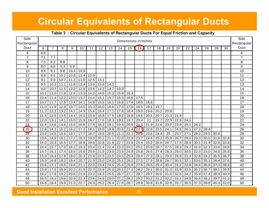
Step 6 : Find the Round Duct Diameter at each section.
Step 7 : Convert the round duct size to rectangular duct by using Table 3,4 & 5.
Table 1 :
Good Installation Excellent Performance 30
Example Problem
Air Qty. CFM Round Duct Size ( in.)
* Rectangular Duct Size ( in.)
** A - B ** B - C 3400 22 26 x 16
C - D D - 5 1700 17 16 x 16
C -1 1700 17 16 x 16
1 - 2 5 - 6 1300 15.2 16 x 12
2 - 3 6 - 7 900 13.3 16 x 9
3 - 4 7 - 8 500 10.8 16 x 6
Duct Section
Notes :-
* :- The sizes which are calculated are inside sizes of duct .** :- For the initial 3m length of the duct the acoustic lining of 1 inch thickness is recommended.
So for section A - B and B - C increase the size by one inch in all sides ( 28 x 18 ), to accommodateacoustic lining.

Example ProblemStep 8 : Add the length of the longest run.
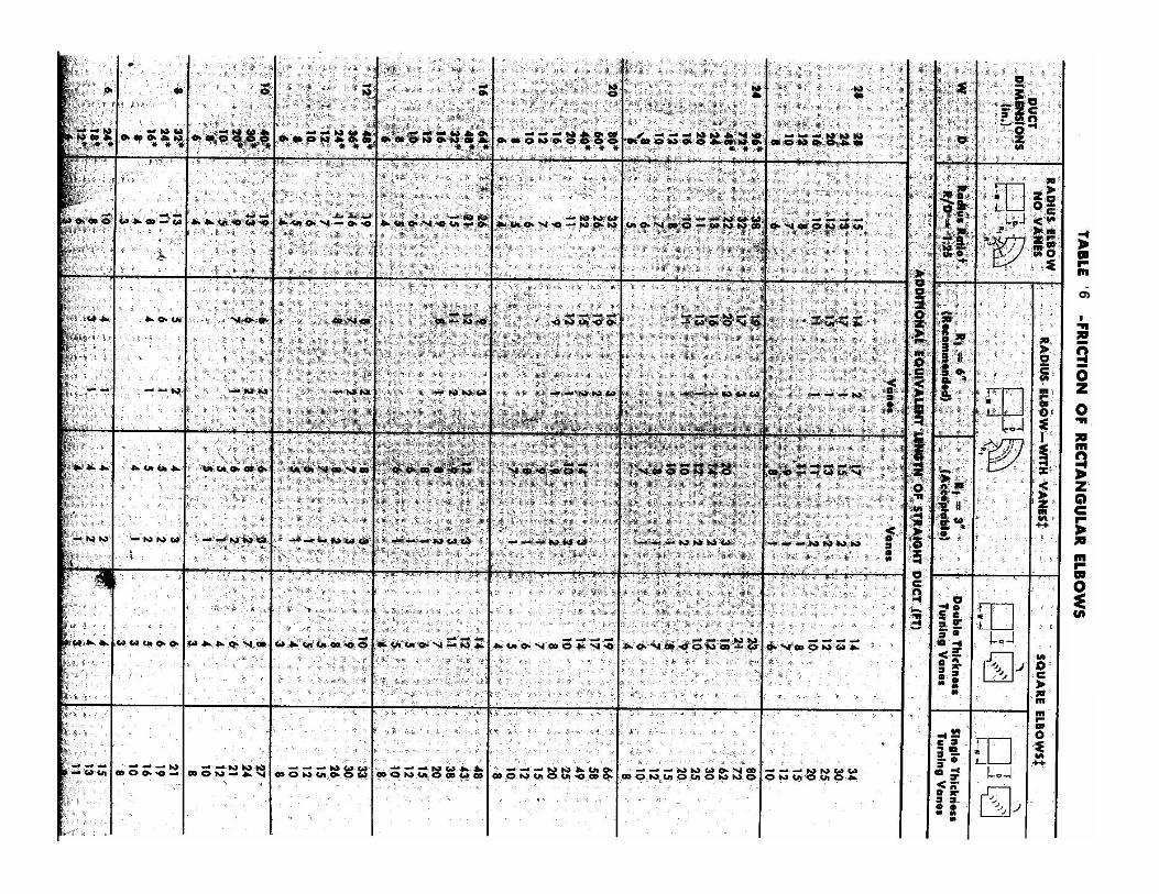
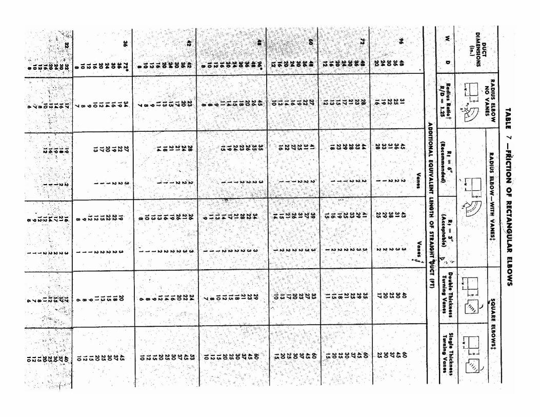
Step 9 : Convert elbows to equivalent length using table 6 & 7 .
Step 9 : Add the length of the longest duct run and equivalent length for elbows.Table 2 :
Good Installation Excellent Performance 31
Example Problem
74TOTAL EQUIVALENT LENGTH1955TOTAL
10Duct7 – 8
10Duct6 - 7
10Duct5 – 6
5DuctD – 5
9Elbow
10DuctC – D
5DuctB – C
10Elbow
5DuctA – B
Add. EquivLength ( ft.)
Length ( ft.)ItemDuct Section
Example Problem
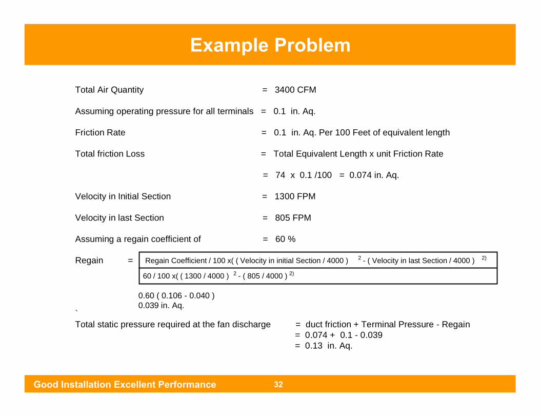
Total Air Quantity = 3400 CFM
Assuming operating pressure for all terminals = 0.1 in. Aq.
Friction Rate = 0.1 in. Aq. Per 100 Feet of equivalent length
Total friction Loss = Total Equivalent Length x unit Friction Rate
= 74 x 0.1 /100 = 0.074 in. Aq.
Velocity in Initial Section = 1300 FPM
Velocity in last Section = 805 FPM
Assuming a regain coefficient of = 60 %
Regain =
`Total static pressure required at the fan discharge = duct friction + Terminal Pressure - Regain
= 0.074 + 0.1 - 0.039= 0.13 in. Aq.
Regain Coefficient / 100 x( ( Velocity in initial Section / 4000 ) 2 - ( Velocity in last Section / 4000 ) 2)
60 / 100 x( ( 1300 / 4000 ) 2 - ( 805 / 4000 ) 2)
0.60 ( 0.106 - 0.040 )0.039 in. Aq.
Good Installation Excellent Performance 32
Example Problem
6 7 8 9 10 11 12 13 14 15 16 17 18 19 20 22 24 26 28 306 6.6 67 7.1 7.7 78 7.5 8.2 8.8 89 8.0 8.6 9.3 9.9 9
10 8.4 9.1 9.8 10.4 10.9 1011 8.8 9.5 10.2 10.8 11.4 12.0 1112 9.1 9.9 10.7 11.3 11.9 12.5 13.1 1213 9.5 10.3 11.1 11.8 12.4 13.0 13.6 14.2 1314 9.8 10.7 11.5 12.2 12.9 13.5 14.2 14.7 15.3 1415 10.1 11.0 11.8 12.6 13.3 14.0 14.6 15.3 15.8 16.4 1516 10.4 11.4 12.2 13.0 13.7 14.4 15.1 15.7 16.3 16.9 17.5 1617 10.7 11.7 12.5 13.4 14.1 14.9 15.5 16.1 16.8 17.4 18.0 18.6 1718 11.0 11.9 12.9 13.7 14.5 15.3 16.0 16.6 17.3 17.9 18.5 19.1 19.7 1819 11.2 12.2 13.2 14.1 14.9 15.6 16.4 17.1 17.8 18.4 19.0 19.6 20.2 20.8 1920 11.5 12.5 13.5 14.4 15.2 15.9 16.8 17.5 18.2 18.8 19.5 20.1 20.7 21.3 21.9 2022 12.0 13.1 14.1 15.0 15.9 16.7 17.6 18.3 19.1 19.7 20.4 21 21.7 22.3 22.9 24.1 2224 12.4 13.6 14.6 15.6 16.6 17.5 18.3 19.1 19.8 20.6 21.3 21.9 22.6 23.2 23.9 25.1 26.2 2426 12.8 14.1 15.2 16.2 17.2 18.1 19.0 19.8 20.6 21.4 22.1 22.8 23.5 24.1 24.8 26.1 27.2 28.4 2628 13.2 14.5 15.6 16.7 17.7 18.7 19.6 20.5 21.3 22.1 22.9 23.6 24.4 25 25.7 27.1 28.2 29.5 30.6 2830 13.6 14.9 16.1 17.2 18.3 19.3 20.2 21.1 22.0 22.9 23.7 24.4 25.2 25.9 26.7 28.0 29.3 30.5 31.6 32.8 3032 14.0 15.3 16.5 17.7 18.8 19.8 20.8 21.8 22.7 23.6 24.4 25.2 26.0 26.7 27.5 28.9 30.1 31.4 32.6 33.8 3234 14.4 15.7 17.0 18.2 19.3 20.4 21.4 22.4 23.3 24.2 25.1 25.9 26.7 27.5 28.3 29.7 31.0 32.3 33.6 34.8 3436 14.7 16.1 17.4 18.6 19.8 20.9 21.9 23.0 23.9 24.8 25.8 26.6 27.4 28.3 29.0 30.5 32.0 33.0 34.6 35.8 3638 15.0 16.4 17.8 19.0 20.3 21.4 22.5 23.5 24.5 25.4 26.4 27.3 28.1 29.0 29.8 31.4 32.8 34.2 35.5 36.7 3840 15.3 16.8 18.2 19.4 20.7 21.9 23.0 24.0 25.1 26.0 27.0 27.9 28.8 29.7 30.5 32.1 33.6 35.1 36.4 37.6 4042 15.6 17.1 18.5 19.8 21.1 22.3 23.4 24.5 25.6 26.6 27.6 28.5 29.4 30.4 31.2 32.8 34.4 35.9 37.3 38.6 4244 15.9 17.5 18.9 20.2 21.5 22.7 23.9 25.0 26.1 27.2 28.2 29.1 30.0 31.0 31.9 33.5 35.2 36.7 38.1 39.5 4446 16.2 17.8 19.2 20.6 21.9 23.2 24.3 25.5 26.7 27.7 28.7 29.7 30.6 31.6 32.5 34.2 35.9 37.4 38.9 40.3 4648 16.5 18.1 19.6 20.9 22.3 23.6 24.8 26.0 27.2 28.2 29.2 30.2 31.2 32.2 33.1 34.9 36.6 38.2 39.7 41.2 4850 16.8 18.4 19.9 21.3 22.7 24.0 25.2 26.4 27.6 28.7 29.8 30.8 31.8 32.8 33.7 35.5 37.3 38.9 40.4 42.0 50
Side Rectangular
Duct
Side Rectangular
Duct
Dimensions in Inches
Table 3 : Circular Equivalents of Rectangular Ducts For Equal Friction and Capacity
Good Installation Excellent Performance 33
Circular Equivalents of Rectangular Ducts

6 7 8 9 10 11 12 13 14 15 16 17 18 19 20 22 24 26 28 3052 17.0 18.7 20.2 21.6 23.1 24.4 25.6 26.8 28.1 29.2 30.3 31.4 32.4 33.4 34.3 36.2 28.0 39.6 41.2 42.8 5254 17.3 19.0 20.5 22.0 23.4 24.8 26.1 27.3 28.5 29.7 30.8 31.9 32.9 33.9 34.9 36.8 38.7 40.3 42.0 43.6 5456 17.6 19.3 20.9 22.4 23.8 25.2 26.5 27.7 28.9 30.1 31.2 32.4 33.4 34.5 35.5 37.4 39.3 41.0 42.7 44.3 5658 17.8 19.5 21.1 22.7 24.2 25.5 26.9 28.2 29.3 30.5 31.7 32.9 33.9 35.0 36.0 38.0 39.8 41.7 43.4 45.0 5860 18.1 19.8 21.4 23.0 24.5 25.8 27.3 28.7 29.8 31.0 32.2 33.4 34.5 35.5 36.5 38.6 40.4 42.3 44.0 45.8 6062 18.3 20.1 21.7 23.3 24.8 26.2 27.6 29.0 30.2 31.4 32.6 33.8 35.0 36.0 37.1 39.2 41.0 42.9 44.7 46.5 6264 18.6 20.3 22.0 23.6 25.2 26.5 27.9 29.3 30.6 31.8 33.1 34.2 35.5 36.5 37.6 39.7 41.6 43.5 45.4 47.2 6466 18.8 20.6 22.3 23.9 25.5 26.9 28.3 29.7 31.0 32.2 33.5 34.7 35.9 37.0 38.1 40.2 42.2 44.1 46.0 47.8 6668 19.0 20.8 22.5 24.2 25.8 27.3 28.7 30.1 31.4 32.6 33.9 35.1 36.3 37.5 38.6 40.7 42.8 44.7 46.6 48.4 6870 19.2 21.0 22.8 24.5 26.1 27.6 29.1 30.4 31.8 33.1 34.3 35.6 36.8 37.9 39.1 41.3 43.3 45.3 47.2 49 7072 39.6 41.8 43.8 45.9 47.8 49.7 7274 40.0 42.3 44.4 46.4 48.4 50.3 7476 40.5 42.8 44.9 47.0 49.0 50.8 7678 40.9 43.3 45.5 47.5 49.5 51.5 7880 41.3 43.8 46.0 48.0 50.1 52.0 8082 41.8 44.2 46.4 48.6 50.6 52.6 8284 42.2 44.6 46.9 49.2 51.1 53.2 8486 42.6 45.0 47.4 49.6 51.6 53.7 8688 43.0 45.4 47.9 50.1 52.2 54.3 8890 43.4 45.9 48.3 50.6 52.8 54.8 9092 43.8 46.3 48.7 51.1 53.4 55.4 9296 44.6 47.2 49.5 52.0 54.4 56.3 96
Side Rectangular
Duct
Side Rectangular
Duct
Dimensions in Inches
Table 4 : Circular Equivalents of Rectangular Ducts For Equal Friction and Capacity
Circular Equivalents of Rectangular Ducts
Good Installation Excellent Performance 34
Circular Equivalents of Rectangular Ducts

32 34 36 38 40 42 44 46 48 50 52 56 60 64 68 72 76 80 84 8832 35.0 3234 36.0 37.2 3436 37.0 38.2 39.4 3638 38.0 39.2 40.4 41.6 3840 39.0 40.2 41.4 42.6 43.8 4042 39.9 41.1 42.4 43.6 44.8 45.9 4244 40.8 42.0 43.4 44.6 45.8 46.9 48.1 4446 41.7 43.0 44.3 45.6 46.8 47.9 49.1 50.3 4648 42.6 43.9 45.2 46.5 47.8 48.9 50.2 51.3 52.6 4850 43.5 44.8 46.1 47.4 48.8 49.8 51.2 52.3 53.6 54.7 5052 44.3 45.7 47.1 48.3 49.7 50.8 52.2 53.3 54.6 55.8 56.9 5254 45.0 46.5 48.0 49.2 50.6 51.8 53.2 54.3 55.6 56.8 57.9 5456 45.8 47.3 48.8 50.1 51.5 52.7 54.1 55.3 56.5 57.8 58.9 61.3 5658 46.6 48.1 49.6 51.0 52.4 53.7 55.0 56.2 57.5 58.8 60.0 62.3 5860 47.3 48.9 50.4 51.8 53.3 54.6 55.9 57.1 58.5 59.8 61.0 63.3 75.7 6062 48.0 49.7 51.2 52.6 54.2 55.5 56.8 58.0 59.4 60.7 62.0 64.3 66.7 6264 48.7 50.4 52.0 53.4 55.0 56.4 57.7 59.0 60.3 61.6 62.9 65.3 67.7 70.0 6466 49.5 51.1 52.8 54.2 55.8 57.2 58.6 59.9 61.2 62.5 63.9 66.3 68.7 71.1 6668 50.2 51.8 53.5 55.0 56.6 58.0 59.5 60.8 62.1 63.4 64.8 67.3 69.7 72.1 74.4 6870 50.9 52.5 54.2 55.8 57.3 58.8 60.3 61.7 63.0 64.3 75.7 68.3 70.7 73.1 75.4 7072 51.5 53.2 54.9 56.5 58.0 59.6 61.1 62.6 63.9 65.2 66.6 69.2 71.7 74.1 76.4 78.8 7274 52.1 53.9 55.6 57.2 58.8 60.4 61.9 63.3 64.8 66.1 67.5 70.1 72.7 75.1 77.4 69.9 7476 52.7 54.6 56.3 57.9 59.5 61.2 62.7 64.1 66.6 67.0 68.4 71.0 73.6 76.1 78.4 80.9 83.2 7678 53.3 55.2 57.0 58.6 60.3 62.0 63.4 64.9 66.4 67.9 69.3 71.8 74.5 77.1 79.4 81.8 84.2 7880 53.9 55.8 57.6 59.3 61.0 62.7 64.1 65.7 67.2 68.7 70.1 72.7 75.4 78.1 80.4 82.8 85.2 87.5 8082 54.5 56.4 58.2 60.0 61.7 63.4 64.9 66.5 68.0 69.5 71.0 73.6 76.3 79.0 81.4 83.8 86.2 88.6 8284 55.1 57.0 58.9 60.7 62.4 64.1 65.7 67.3 68.8 70.3 71.8 74.5 77.2 79.9 82.4 84.8 87.2 89.6 91.9 8486 55.7 57.6 59.5 61.3 63.0 64.8 66.4 68.0 69.5 71.1 72.6 75.4 78.1 80.8 83.3 85.8 88.2 90.6 92.9 8688 56.3 58.2 60.1 62.0 63.7 65.4 67.0 68.7 70.3 71.8 73.4 76.3 79.0 81.6 84.2 86.8 89.2 91.6 93.9 96.3 8890 56.9 58.8 60.7 62.6 64.4 66.0 67.8 69.4 71.1 72.6 74.2 77.1 79.9 82.5 85.1 87.8 90.2 92.6 94.9 97.3 9092 57.4 59.4 61.3 63.2 65.0 66.8 68.5 70.1 71.8 73.3 74.9 77.9 80.8 83.4 86.0 88.7 91.2 93.6 95.9 98.3 9294 57.9 60.0 61.9 63.8 65.6 67.5 69.2 70.8 72.5 74.1 75.6 78.7 81.7 84.3 86.9 89.6 92.1 94.6 96.9 99.3 9496 58.4 60.5 62.4 64.6 66.2 68.2 69.8 71.5 73.2 74.3 76.3 79.4 82.6 85.2 87.8 90.5 93.0 95.6 97.9 100.3 96
Side Rectangular
Duct
Dimensions in InchesSide
Rectangular Duct
Table 5 : Circular Equivalents of Rectangular Ducts For Equal Friction and Capacity
Circular Equivalents of Rectangular Ducts
Good Installation Excellent Performance 35
Circular Equivalents of Rectangular Ducts
66
7

Components of Ducting
Good Installation Excellent Performance 38
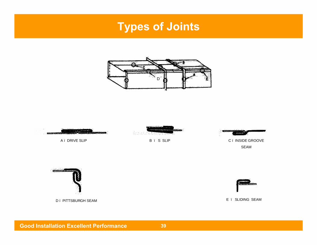
Types of JointsTypes of Joints
Good Installation Excellent Performance 39
D
A – DRIVE SLIP B – S SLIP C – INSIDE GROOVE
SEAM
E – SLIDING SEAMD – PITTSBURGH SEAM

Plenum
Supply Plenum Supply
Volume Control Damper
Supply
Plenum is used to convert turbulent flow to laminar Flow.
It is to distribute the air.
By using plenum noise will also reduce.
Good Installation Excellent Performance 40
Plenum

Plenum DesignGenerally for Low Velocity Application
Velocity in Plenum = 800 fpm
D = Depth of the plenum= 2.5 x Blower Diameter
Q = A x V
= W x H x V
Where : -
W = Width of the plenumH = Height of the plenumV = Velocity in fpmQ = Air Flow in CFM
ex : - Take an example of 8.5 Ton. Assume height ( H ) as 1.5 feet
3400 = A x 800 = W x 1.5 x 800
W = 3400 / 800 x 1.5 = 2.83 Feet
D = 2.5 x 11 = 27.5 inches
* 11 inches is the blower diameter for 8.5 ton
IDU
Flexible Connection
IDU W
D
H
PlenumSupply
Supply
Supply
Top View
Side View
Good Installation Excellent Performance 41
Plenum Design
*

Grilles , Diffusers
Grilles Diffusers
Grilles are preferred for side throw. Diffusers are preferred for downwardthrow.
It may be Round or Square
Good Installation Excellent Performance 42
Grilles , Diffusers
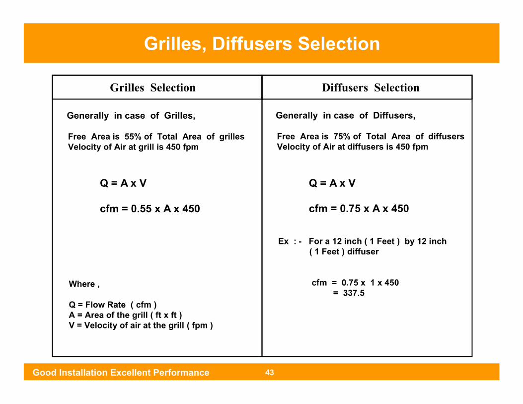
Grilles Selection Diffusers Selection
Where ,
Q = Flow Rate ( cfm )A = Area of the grill ( ft x ft )V = Velocity of air at the grill ( fpm )
Generally in case of Grilles,
Free Area is 55% of Total Area of grillesVelocity of Air at grill is 450 fpm
Q = A x V
cfm = 0.55 x A x 450
Generally in case of Diffusers,
Free Area is 75% of Total Area of diffusersVelocity of Air at diffusers is 450 fpm
Q = A x V
cfm = 0.75 x A x 450
Ex : - For a 12 inch ( 1 Feet ) by 12 inch ( 1 Feet ) diffuser
cfm = 0.75 x 1 x 450 = 337.5
Grilles, Diffusers Selection
Good Installation Excellent Performance 43
Turning Vanes , Splitter Vanes
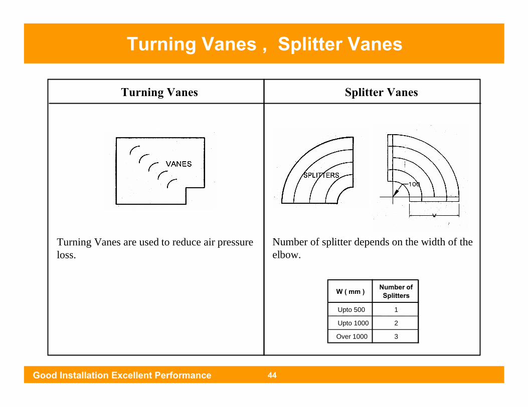
Turning Vanes Splitter Vanes
Turning Vanes are used to reduce air pressure loss.
Number of splitter depends on the width of the elbow.
W ( mm ) Number of Splitters
Upto 500 1
Upto 1000 2
Over 1000 3
Good Installation Excellent Performance 44
Turning Vanes , Splitter Vanes

30 Degree
30 ~ 45 Degree
Transition Ducts are part of main duct which are used to connect duct of one size or shape to another size or shape.
Design of Transition Duct (Transformation Pieces)
Good Installation Excellent Performance 45

Usually we take care of Supply Ducting or Supply path,
How about return ducting or return path
Disadvantages :
> Cooling Efficiency of machine will decrease.
> High Noise, Also poor access for service.
Don’t Do’s
Front View
Machine
Wall
Wall
H
Minimum Clearance H
Top View
If H is height of the machine
Good Installation Excellent Performance 46
Do’s and Don’t of Ducting

Does and Don’t of Ducting
Don’t Do’s
Duct With No Cross Braking
Cross Braking
Cross Braking after every 4 Feet
4 Feet 4 Feet
Breathing of the Duct - Results in Noise No Breathing Noise
Good Installation Excellent Performance 47
Do’s and Don’t of Ducting
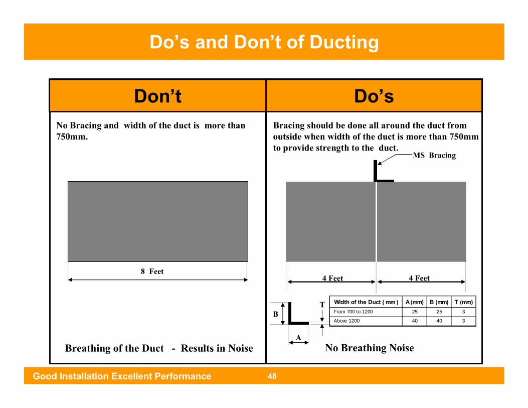
Don’t Do’sNo Bracing and width of the duct is more than750mm.
Breathing of the Duct - Results in Noise No Breathing Noise
Bracing should be done all around the duct from outside when width of the duct is more than 750mmto provide strength to the duct.
4 Feet 4 Feet 8 Feet
MS Bracing
T
A
B Width of the Duct ( mm ) A (mm) B (mm) T (mm)
From 700 to 1200 25 25 3
Above 1200 40 40 3
Good Installation Excellent Performance 48
Does and Don’t of DuctingDo’s and Don’t of Ducting
Does and Don’t of Ducting
Don’t Do’s
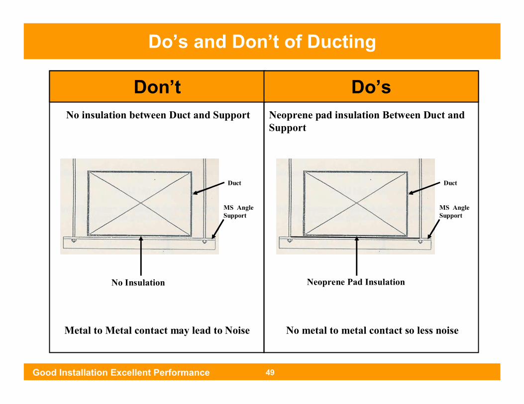
Duct
MS Angle Support
No Insulation
Duct
MS Angle Support
Neoprene Pad Insulation
No insulation between Duct and Support Neoprene pad insulation Between Duct and Support
Metal to Metal contact may lead to Noise No metal to metal contact so less noise
Good Installation Excellent Performance 49
Do’s and Don’t of Ducting

Does and Don’t of Ducting
GrillMAIN SUPPLY DUCT
FRONT VIEW
Grill
MAIN SUPPLY DUCT
TOP VIEW
2 or 3 inch ductconnection
Very high Noise
Grill
MAIN SUPPLY DUCT
FRONT VIEW
Grill
MAIN SUPPLY DUCT
TOP VIEW
Good Installation Excellent Performance 50
Do’s and Don’t of Ducting
Don’t Do’s
Does and Don’t of Ducting
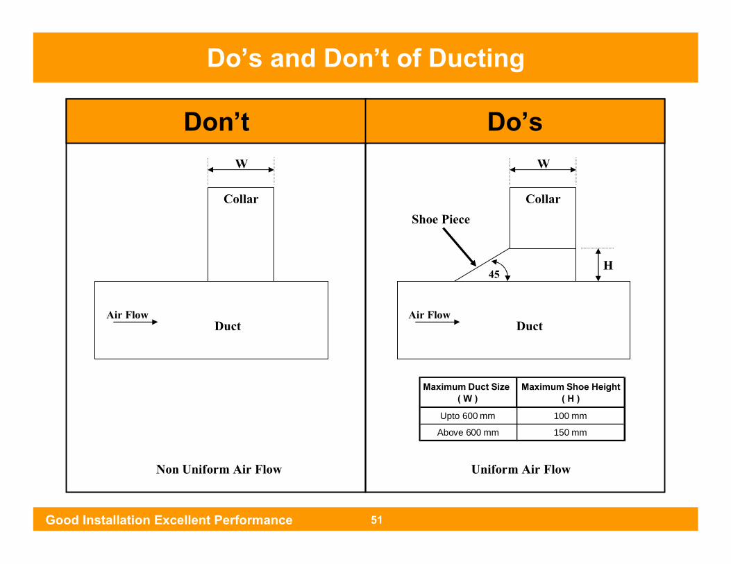
Don’t Do’s
Maximum Duct Size ( W )
Maximum Shoe Height ( H )
Upto 600 mm 100 mm
Above 600 mm 150 mm
DuctAir Flow
Collar
W
45H
Uniform Air Flow
DuctAir Flow
Collar
W
Non Uniform Air Flow
Shoe Piece
Good Installation Excellent Performance 51
Do’s and Don’t of Ducting
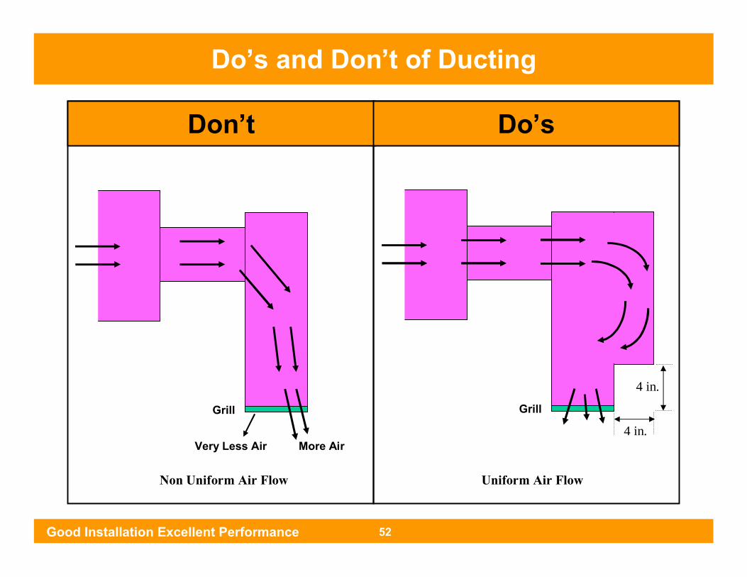
Does and Don’t of Ducting
Don’t Do’s
Grill
More AirVery Less Air
Grill
4 in.
4 in.
Uniform Air FlowNon Uniform Air Flow
Good Installation Excellent Performance 52
Do’s and Don’t of Ducting
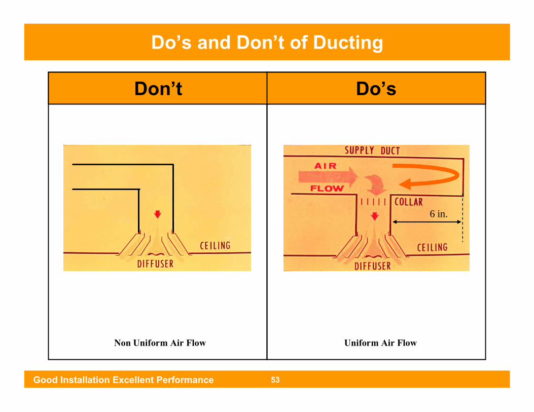
Does and Don’t of Ducting
Don’t Do’s
Uniform Air FlowNon Uniform Air Flow
Good Installation Excellent Performance 53
Do’s and Don’t of Ducting
6 in.
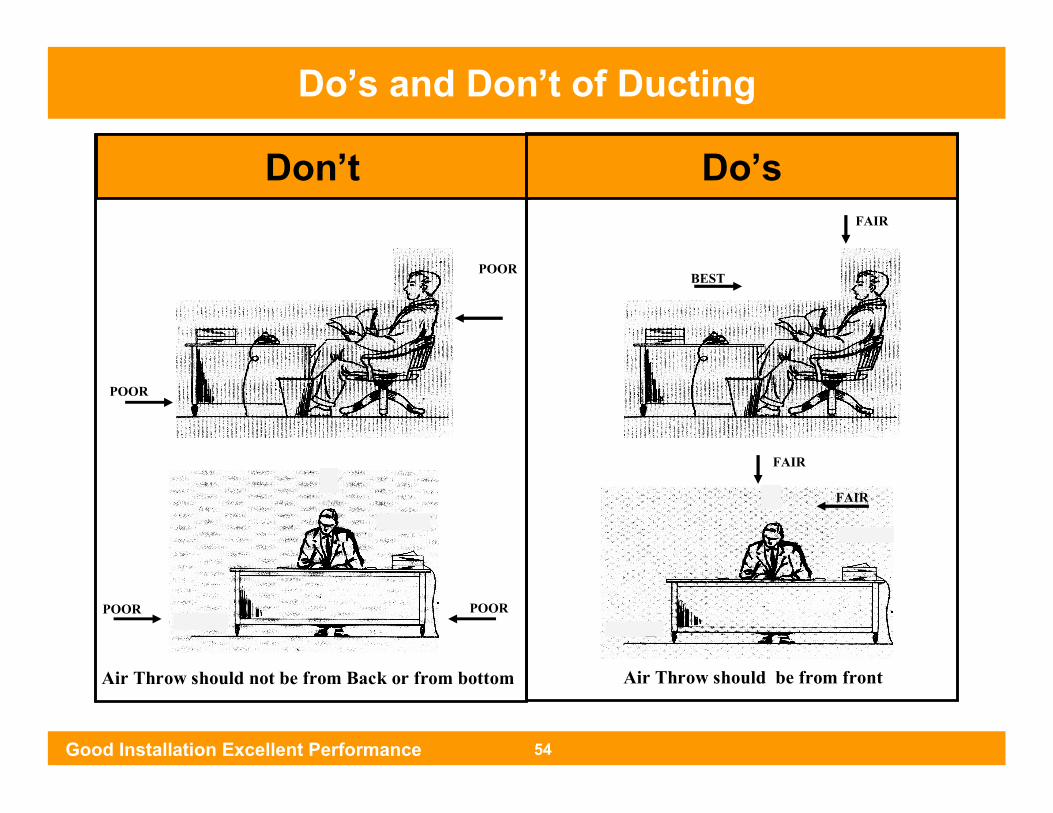
Don’t Do’s
POOR POOR
POOR
POOR
FAIR
FAIR
Air Throw should not be from Back or from bottom Air Throw should be from front
Do’s and Don’t of Ducting
Good Installation Excellent Performance 54
BEST
FAIR

Good Installation Excellent Performance 55
LEGEND
Good Installation Excellent Performance 56
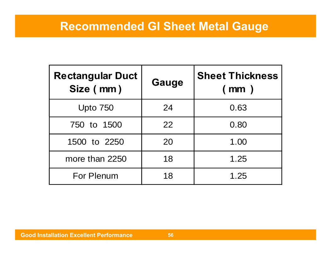
Recommended GI Sheet Metal Gauge
Rectangular Duct Size ( mm ) Gauge Sheet Thickness
( mm )
Upto 750 24 0.63
750 to 1500 22 0.80
1500 to 2250 20 1.00
more than 2250 18 1.25
For Plenum 18 1.25
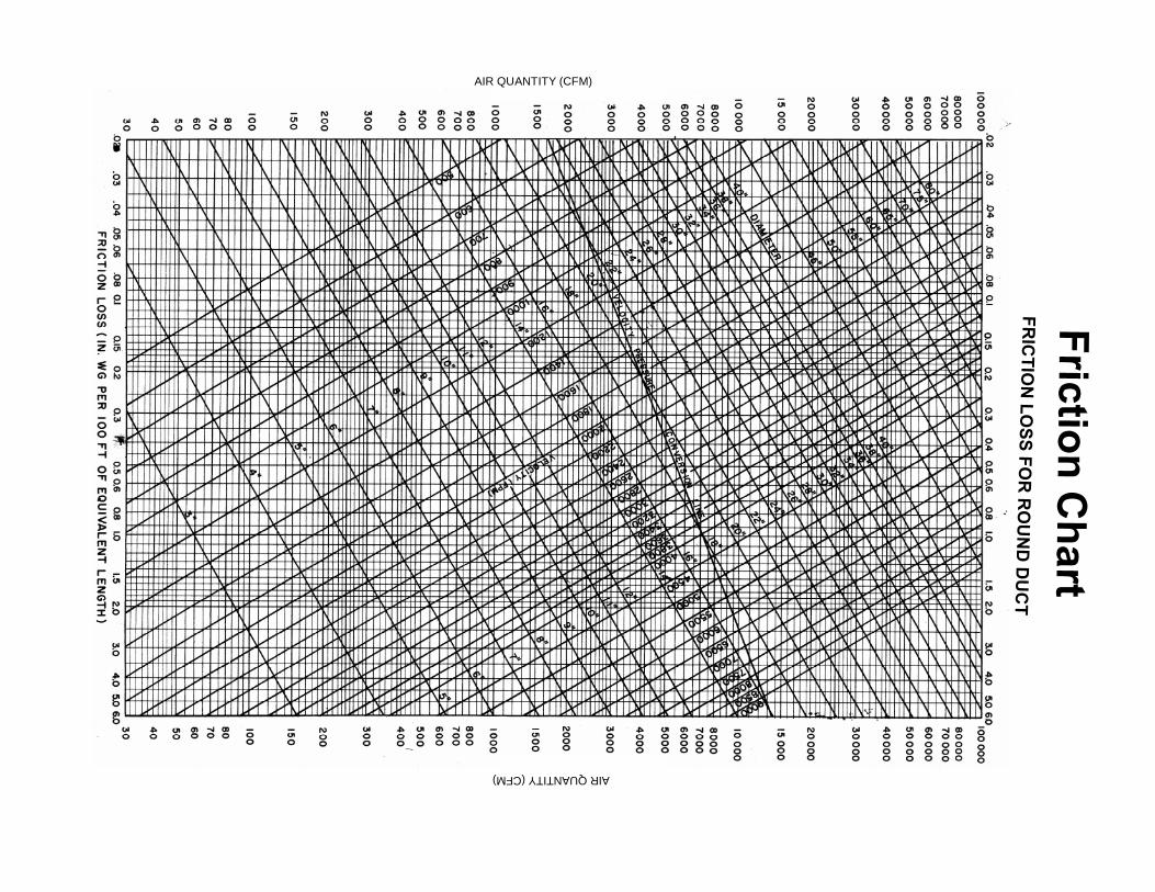
Friction Chart
FRIC
TION
LOSS FO
R R
OU
ND
DU
CT
AIR QUANTITY (CFM)
AIR QUANTITY (CFM)
Related Documents