Dual Roller Fascia Coupled FlexShades Assembly and Installation Instructions Copyright © 2017 Draper Inc. Form DRFCoupledFlexShade_Inst17 Printed in U.S.A. If you encounter difficulties installing or servicing your Coupled FlexShades, call your dealer or Draper, Inc., Spiceland, Ind., (765) 987-7999; or fax (765) 987-7142. Caution 1 Upon receiving your Coupled FlexShades, open and inspect to make sure you have received the proper sizes, fabrics, and mounting hardware. 2 Make sure to install the coupler assemblies in a clean area, and to use a clean drop cloth, to ensure the fabric is not damaged or soiled. 3 Make sure all coupler components are fully seated in the rollers. 4 The coupler assemblies MUST be installed into rollers in the correct configuration. Having a coupler assembly in the wrong location could cause the shade to fall or otherwise fail. 5 Be careful not to break the coupler assemblies during installation. If an assembly is cracked or broken, or the outer ring is damaged, obtain a replace- ment coupler assembly. DO NOT USE the damaged assembly. 6 Watch your fingers! Gloves are recommended when installing couplers into the rollers. 2" Rollers OR C177.059SA C177.062SA OR C177.058SA C177.061SA Idler End Coupler Operator End Coupler 3" Rollers C103.069 C177.061SA AND C103.069 C177.062SA AND Idler End Coupler Operator End Coupler Please Note: The retractable shaft needs to be pointing toward the opposite end of the motor and oriented that direction for the whole unit. Please Note: Notches in the tube need to be lined up with the "keys" on the couplers. Idler End Assembly: 1 Insert coupler assembly into roller. Making sure the notch in the tube is lined up with the "key" on the coupler, press until the assembly is fully seated in the roller. Caution: Make sure the locking ring on the idler end coupler assembly is fully tightened before installing roller into brackets. There should be no play in the locking ring. If the locking ring is loose, then the idler is in "height ad- justment" mode. Make sure you are wearing a heavy glove on the hand you will be using to grip the locking ring locking ring. Tighten the locking ring until it is fully locked and you cannot rotate it any further. Check to make sure is it tight and will not work loose. If you cannot tighten by hand, you may need to use a flat screwdriver or other tool to assist. Operator End Assembly: Please Note: Operator end coupler assemblies will not slide straight in to the roller tube. 1 Insert assembly into the roller, with the "key" slightly off center from the notch. 2 Once assembly is far enough in that the ribs are past end of the notch, rotate the coupler until the notch is lined up with the "key" on the coupler. Please Note: If you have difficulty fully seating the assembly in the roller, you may retract the shaft (if applicable) and tap the assembly with a rubber mal- let. Be careful not to damage the coupler. Idler End Assembly: 1 Insert coupler assembly adapter into roller. Making sure the notch in the adapter is lined up with the notch in the coupler, press until the adapter is fully seated in the roller. 2 Insert coupler assembly into adapter. Making sure the notch in the inside of the adapter is lined up with the "key" on the coupler, press until the assem- bly is fully seated. Caution: Make sure the locking ring on the idler end coupler assembly is fully tightened before installing roller into brackets. There should be no play in the locking ring. If the locking ring is loose, then the idler is in "height adjustment" mode. Make sure you are wearing a heavy glove on the hand you will be using to grip the locking ring. Tighten the locking ring until it is fully locked and you cannot rotate it any further. Check to make sure is it tight and will not work loose. If you cannot tighten by hand, you may need to use a flat screwdriver or other tool to assist. Operator End Assembly: 1 Follow the same steps used for the idler end. Please Note: If you have difficulty fully seating the adapter in the roller, or the coupler assembly in the adapter, you may retract the shaft (if applicable) and tap the assembly with a rubber mallet. Be careful not to damage the coupler. Please Note: The retractable shaft needs to be pointing toward the opposite end of the motor and oriented that direction for the whole unit. Please Note: The operator will already be installed in the operator-end roller; the sliding pin idler will also be installed in the idler-end roller. You will only need to install the coupler assemblies.

Welcome message from author
This document is posted to help you gain knowledge. Please leave a comment to let me know what you think about it! Share it to your friends and learn new things together.
Transcript
Dual Roller Fascia Coupled FlexShades Assembly and Installation Instructions
Copyright © 2017 Draper Inc. Form DRFCoupledFlexShade_Inst17 Printed in U.S.A.If you encounter difficulties installing or servicing your Coupled FlexShades, call your dealer or Draper, Inc., Spiceland, Ind., (765) 987-7999; or fax (765) 987-7142.
Caution1 Upon receiving your Coupled FlexShades, open and inspect to make sure you have received the proper sizes, fabrics, and mounting hardware.2 Make sure to install the coupler assemblies in a clean area, and to use a clean drop cloth, to ensure the fabric is not damaged or soiled.3 Make sure all coupler components are fully seated in the rollers.4 The coupler assemblies MUST be installed into rollers in the correct configuration. Having a coupler assembly in the wrong location could cause the shade to fall or otherwise fail.5 Be careful not to break the coupler assemblies during installation. If an assembly is cracked or broken, or the outer ring is damaged, obtain a replace- ment coupler assembly. DO NOT USE the damaged assembly.6 Watch your fingers! Gloves are recommended when installing couplers into the rollers.
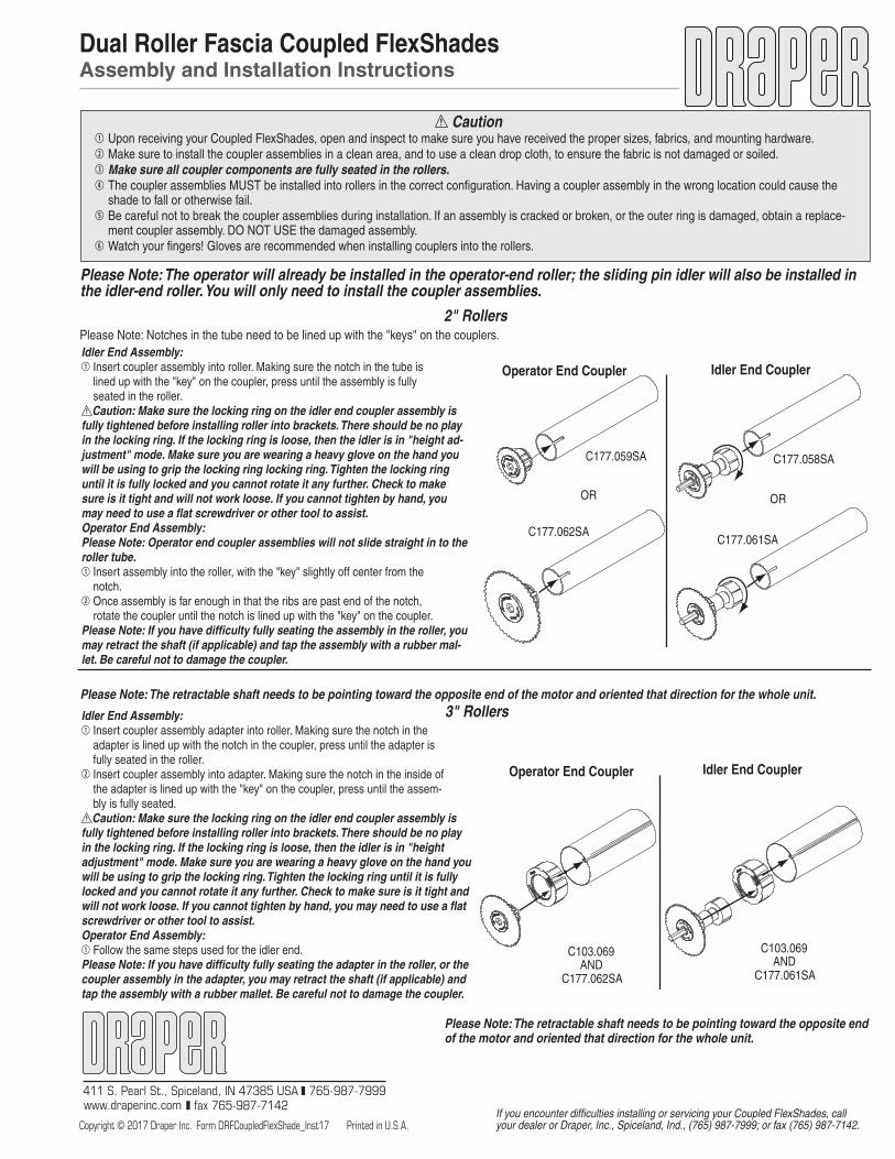
2" Rollers
OR
C177.059SA
C177.062SA
OR
C177.058SA
C177.061SA
Idler End CouplerOperator End Coupler
3" Rollers
C103.069
C177.061SAAND
C103.069
C177.062SAAND
Idler End CouplerOperator End Coupler
Please Note: The retractable shaft needs to be pointing toward the opposite end of the motor and oriented that direction for the whole unit.
Please Note: Notches in the tube need to be lined up with the "keys" on the couplers.Idler End Assembly:1 Insert coupler assembly into roller. Making sure the notch in the tube is lined up with the "key" on the coupler, press until the assembly is fully seated in the roller.
Caution: Make sure the locking ring on the idler end coupler assembly is fully tightened before installing roller into brackets. There should be no play in the locking ring. If the locking ring is loose, then the idler is in "height ad-justment" mode. Make sure you are wearing a heavy glove on the hand you will be using to grip the locking ring locking ring. Tighten the locking ring until it is fully locked and you cannot rotate it any further. Check to make sure is it tight and will not work loose. If you cannot tighten by hand, you may need to use a flat screwdriver or other tool to assist.Operator End Assembly:Please Note: Operator end coupler assemblies will not slide straight in to the roller tube.1 Insert assembly into the roller, with the "key" slightly off center from the notch.2 Once assembly is far enough in that the ribs are past end of the notch, rotate the coupler until the notch is lined up with the "key" on the coupler.Please Note: If you have difficulty fully seating the assembly in the roller, you may retract the shaft (if applicable) and tap the assembly with a rubber mal-let. Be careful not to damage the coupler.
Idler End Assembly:1 Insert coupler assembly adapter into roller. Making sure the notch in the adapter is lined up with the notch in the coupler, press until the adapter is fully seated in the roller.2 Insert coupler assembly into adapter. Making sure the notch in the inside of the adapter is lined up with the "key" on the coupler, press until the assem- bly is fully seated.
Caution: Make sure the locking ring on the idler end coupler assembly is fully tightened before installing roller into brackets. There should be no play in the locking ring. If the locking ring is loose, then the idler is in "height adjustment" mode. Make sure you are wearing a heavy glove on the hand you will be using to grip the locking ring. Tighten the locking ring until it is fully locked and you cannot rotate it any further. Check to make sure is it tight and will not work loose. If you cannot tighten by hand, you may need to use a flat screwdriver or other tool to assist.Operator End Assembly:1 Follow the same steps used for the idler end.Please Note: If you have difficulty fully seating the adapter in the roller, or the coupler assembly in the adapter, you may retract the shaft (if applicable) and tap the assembly with a rubber mallet. Be careful not to damage the coupler.
Please Note: The retractable shaft needs to be pointing toward the opposite end of the motor and oriented that direction for the whole unit.
Please Note: The operator will already be installed in the operator-end roller; the sliding pin idler will also be installed in the idler-end roller. You will only need to install the coupler assemblies.

Installation InstructionsDual Roller Fascia Coupled FlexShades by Draper
Copyright © 2017 Draper Inc. Form Fascia_Coupled_DualRoller_Inst17 Printed in U.S.A.
If you encounter difficulties installing or servicing your Coupled FlexShades, call
your dealer or Draper, Inc., Spiceland, Ind., (765) 987-7999; or fax (765) 987-7142.
Continued on Page 2
Caution1 Upon receiving your Coupled FlexShades, open and inspect to make sure you have received the proper sizes, fabrics, and mounting hardware. Controls may be shipped separately, or in same carton. Do not discard. Open cartons lengthwise. DO NOT use a knife to open.2 Installation of this product requires two people.3 Before beginning installation, practice extending and retracting the coupler shaft in a fabric/roller assembly, following instructions in the "Operating the Retractable Coupler Shaft" section below.4 Install your Coupled FlexShades as level and square as possible, to ensure proper operation and correct fabric hang. Before installation, mark a level line across all windows to ensure a level installation. Use a carpenter’s level to check. There is some adjustment built into the endcaps and brackets, but shims may be required if mounting surface is not plumb, square and true.5 Remove all obstructions to proper shade operation.6 All motors should be tested and limits set using test cord before electrician wires shade. 7 Before connecting switches, controls, or electrical, make sure power is off. Wiring indicated in diagram by dashed lines must be completed by electrician. 8 Do not wire motors in parallel without written permission from Draper. 9 It is the installer’s responsibility to make sure appropriate fasteners are used for mounting surface.10 Please read the following installation guidelines thoroughly and follow them carefully. Failure to do so may cause product to fall or otherwise fail, and invalidates warranty.Please Note: Custom products/installations may not be reflected by this document. Call Draper, Inc. if you have questions about your installation.
Mounting/Assembly(Remember, this takes two people)
Operator-end Bracket Assembly:1 Before mounting shades, verify measurements on the card provided with the shade, and ensure the brackets are installed at the correct width.2 Measure and mark wall, jamb or ceiling for placement of mounting brackets/ endcaps. Mark a level line across all windows to ensure a level installation. Mark the outer edges of the operator- and idler-end endcaps, and the center locations of the coupler brackets. Locations are determined by: A Operator-end panel width; B Intermediate panel width (s); and C Idler-end panel width.
Figure 1
First (Operator-end) Fabric/Roller Assembly (see Fig. 4):
1 If desired, the proper location of the coupler bracket assembly can be verified. Otherwise, proceed to step 2. A One person attaches the operator end to the operator end bracket. B The second person slides the coupler bracket onto the coupler shaft of the fabric/roller assembly to be installed, and holds in place. C Verify and mark location and set fabric/roller assembly aside.2 Install first coupler bracket assembly to mounting surface. 3 Make sure the operator-end fabric/roller assembly's coupler shaft is completely retracted (see "Operating the Retractable Shaft" and Fig. 1).4 Raise first rear/upper fabric/roller assembly into place. While one person inserts the operator end of fabric/roller assembly into the operator-end bracket, the sec- ond person lifts the coupler end up next to the coupler bracket assembly, then extends the coupler shaft to the intermediate position by rotating the ring clockwise about 1/3 of a turn (see "Operating the Retractable Shaft" and Fig. 1). This will hold the first unit in place during installation of the next panel.5 For motorized shades, connect power so the shade can be operated and adjusted.6 Operate the shade to ensure proper fabric tracking and to set up and down limits (see sections on limit adjustment and field adjustments).7 Raise shade to upper limit.Intermediate Fabric/Roller Assembly (see Fig. 5):Please Note: Skip this section if your unit only has two panels
1 If desired, the proper location of the next bracket can be verified. Otherwise, proceed to step 2.
Operating the Retractable Coupler Shaft Draper Coupled FlexShades utilize a locking retractable shaft to hold roller as-semblies in place and link panels together. The retractable coupler shaft on has three distinct positions: fully extended, intermediate, and fully retracted. To retract the coupler shaft from fully extended to the intermediate position, grasp the roller with one hand while rotating the metal ring counterclockwise (as you view the face of the coupler assembly) approximately ½ of a turn with the other; this will leave the shaft extended approximately ½". To retract the coupler shaft fully, rotate the metal ring counterclockwise (as you view the face of the coupler assembly) an additional 1/3 of a turn. To lock shaft in place when extended, rotate metal ring clockwise ¼ turn.Please Note: There is no retractable shaft in the idler end assembly on the idler end shade (furthest from the operator). This idler assembly utilizes a sliding pin and retainer clip.
Fully Retracted Intermediate Fully ExtendedSliding Pin
(Idler End Shade Only)
3 Mount the operator-end bracket assembly (see Fig. 3 for bracket/endcap types). Make sure the outside edge is aligned with the marked location. The installer is responsible for selecting mounting hardware appropriate for site conditions.
Figure 3
CautionBe careful during installation and adjustment of coupled shades; fingers may slip, causing possibly severe cuts and/or scrapes. If possible, wear gloves that are flexible enough to allow you to adjust the metal wheel but tough enough to stand up to scrapes from surrounding metal or other surfaces.
Please Note: These instruction steps are for installing brackets/endcaps one at a time, as you go. Brackets may also all be installed at the same time, prior to installing roller/fabric assemblies. If you do install all brackets first, please be certain of measurements and locations. You might wish to assemble the unit on a flat, clean surface and verify measurements before attaching brackets/endcaps.
Figure 4
Figure 5
Motor EndEndcap-Fascia
Idler EndEndcap-Fascia
Coupler BracketAssembly-Fascia

Page 2 of 4Dual Roller Fascia Coupled FlexShades by Draper
NOTE: Test shade operation. If shade direction does not correspond with the switch orientation, turn power back off then switch the red and black wires from the motor to the switch.
Single Shade Wiring DiagramFor multiple shade or low voltage wiring consult diagrams provided with control.
Internal Shade WiringWhite (Common)BlackRedGreen (Ground)
Controlswitch
Single gang box by othersMin. 4" x 2
1/8" x 1 7/8" deepRed
BlackBlack
To 110-120V Line
Dashed wiring by electrician
Electrical ConnectionsMotorized shade operates on 110-120V, 60 Hz. current. Shade is shipped with internal wiring complete and control switch(es) fully boxed, and standardly sup-plied with a 6' cable lead. Longer lead can be substituted by removing two screws in motor end of roller, removing lead, plugging new lead in, and replacing screws. Wire to connect shade to switch(es) and switch(es) to power supply should be furnished by installer. Connections should be made in accordance with attached wiring diagram, and wiring should comply with national and local electrical codes.DO NOT wire motors in parallel without written permission from Draper. All operating switches should be “off” before power is connected.
www.draperinc.com (765) 987-7999
Field AdjustmentsTelescoping Fabric Each Draper Solar Control Shade is tested to ensure proper operation. Even with this testing, some field adjustments may be needed for telescoping. If shade is telescoping, place a piece of high quality gaffer tape about 1" wide on the exposed roller (where the fabric will cover it) on the side that you want the fabric drawn toward. For example: if fabric is tracking to the left, place the tape on the right side.
2 Install the next coupler bracket to mounting surface.3 The end of the previously-installed coupler shaft should be flush with the out- side edge of the bearing. If it is extended beyond the bearing, you can retract the coupler shaft of the previously installed roller to the intermediate position (see "Operating the Retractable Shaft" and Fig. 1).4 Lift both ends of the intermediate fabric/roller assembly into place and align between the rear/upper brackets.5 One person fully extends coupler shaft of previously installed roller by rotating the metal ring clockwise about ½ of a turn when viewing the face of the cou- pler assembly (see "Operating the Retractable Shaft" and Fig. 1), until the shaft extends fully into the receiver of the fabric/roller assembly being installed.6 The other person extends the coupler shaft of the fabric/roller assembly being installed to the intermediate position by rotating the ring clockwise about 1/3 of a turn (see "Operating the Retractable Shaft" and Fig. 1) so the end of the shaft is flush with the outside edge of the bearing.7 Operate the shade to ensure proper fabric tracking.8 Lower the unit (all shades will operate simultaneously) to lower limit.9 If needed, the fabric panel heights can be adjusted so that the bottom edges of the fabric panels are aligned. On large units, this procedure should be done on only one panel at a time to minimize the amount of fabric weight that must be supported during the adjustment procedure. See Fabric/Roller Assembly Alignment” on page 4 for instructions.10 Repeat steps above under "Second Fabric/Roller Assembly" for additional intermediate panels.Final (Idler-end) Fabric/Roller Assembly (see Fig. 6):
1 If desired, the proper location of the next bracket assembly can be verified. Otherwise, proceed to step 2.2 Install idler-end bracket/endcap assembly.3 Retract coupler shaft of previously installed roller to the intermediate position (see "Operating the Retractable Shaft" and Fig. 1). The end of the coupler shaft should be flush with the outside edge of the bearing.4 Lift both ends of the idler-end fabric/roller assembly into place and align between the brackets/endcaps.5 One person places the idler-end sliding shaft onto the idler end bracket (see Fig. 6). Lock shaft in place by placing retaining clip on shaft.6 The other person fully extends coupler shaft of previously installed roller by rotating the metal ring clockwise about ½ of a turn when viewing the face of the coupler assembly (see "Operating the Retractable Shaft" and Fig. 1), until the shaft extends fully into the receiver of the idler-end fabric/roller assembly.
Caution: Make sure shaft is locked in place with retaining clip on shaft.7 Operate the unit to ensure proper fabric tracking.8 Lower the unit (all shades will operate simultaneously) to lower limit.9 If needed, the fabric panel heights can be adjusted so that the bottom edges of the fabric panels are aligned. On large units, this procedure should be done on only one panel at a time to minimize the amount of fabric weight that must be supported during the adjustment procedure. See Fabric/Roller Assembly Alignment” on page 4 for instructions.10 Repeat steps followed for rear/upper fabric/roller assemblies under First (Operator-end) Fabric/Roller Assembly, Second Fabric/Roller Assembly and Final (Idler-end) Fabric/Roller Assembly sections above for lower/front fabric/ roller assemblies.
Figure 7
Figure 6
Cleaning and Maintenance Window covering products manufactured by Draper, when properly in-stalled, should require no operational maintenance or lubrication. Most of Draper’s standard fabrics may be cleaned at the window by vacuuming with a soft brush attachment. They may also be cleaned by using a sponge or soft cloth and mild solution of warm soapy water. A dishwashing liquid, such as Ivory liquid, is recommended. A clean dry cloth is recommend-ed for the metal finish. Exceptions are Flocké and Roc-Rol fabrics, which must be cleaned with a dry art sponge.
Please Note: For low voltage wiring requirements, Draper recommends con-sulting with a professional low voltage electrical contractor. It is very important that shielded and stranded CAT 5 cable be used to prevent any electrical interference.
Limit Switch Adjustments
Limit Adjustments (Push Button Limits)1 Fully depress both limit switch push buttons, then operate wall switch to make sure system works properly. 2 Raise shade to desired “up” stop position. 3 Set upper limit by depressing and releasing the proper (back) push button. 4 Lower shade to desired “down” stop position. 5 Set lower limit by depressing and releasing the proper (front) push button.
CAUTION: Be sure all switches are in “off” position before adjusting limit switches. Always be prepared to shut off manually when new adjustment is being tested. Do not allow the shade roller to become exposed by running the shade fabric too far down. Shade may be severely damaged if allowed to run too far up or down. Each shade’s limit switch must be set if using group control system.
Page 3 of 4
www.draperinc.com (765) 987-7999
Limit Adjustments (Built-in Low Voltage Motors—See Fig. 8)1 Connect the ILT switch to the motor via the terminal blocks, or via the modular port using four conductor modular cable. When using modular cable, the cable connectors MUST NOT be crimped in reverse, as with standard telephone cable.2 Set the slide switch to the lower position. Press and hold the DOWN button on the switch to move the shade to the desired lower limit. If the shade moves in the opposite direction, release the DOWN button and depress the STOP button. This will reverse the operation of the UP and DOWN switches.3 Set the slide switch to the higher position. Move the shade to the desired upper limit by pressing and holding the UP button on the wall switch.4 Return the slide switch to the center position to return to normal operation.
5 To set the shade to an alternate format position, move the shade to the desired position and press the STOP button. Press and hold STOP for at least three seconds to record the position. Please Note: Pressing and releasing the UP button on the switch will move the shade to its upper limit. Pressing and releasing the DOWN button will move the shade to its lower limit. While the motor is in motion, pressing STOP for less than two seconds will stop the viewing surface at its present position. Once the motor is stopped, pressing the STOP button will move the shade to its alternate format position. Pressing and holding the STOP button, when the motor is at rest or in motion, for at least three seconds will record a new alternate format position.
Dimensions—Dual Roller Fascia Coupled FlexShades
13/16" * 15/16" 15/16"
Operator end
Coupler assembly
FlexShade with motorFlexShade without motor FlexShade without motor
15/16"
FlexShade without motor
Idler end
13/16" *15/16"
FlexShade without motor
* This number may be greater, depending on motor selection. Contact Draper for motor verification.
Dual Roller Fascia Coupled FlexShades by Draper
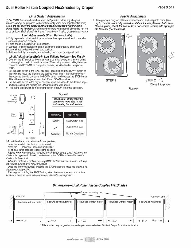
Fascia Attachment1 Place groove along top of fascia over endcaps, and snap into place (see Fig. 9). Fascia is not fully seated until it clicks into place on both ends. Once in place, check for secure fit. If not secure, secure with appropri- ate fastener (not included).
Figure 9
STEP 2Clicks into place
STEP 1
Figure 8
POSITION FUNCTION
DOWN
UP
CENTER
Set LOWER limit
Set UPPER limit
Normal Operation
POSITION FUNCTION
DOWN
UP
CENTER
Set LOWER limit
Set UPPER limit
Normal Operation
S T O P
To Motorwith
Built-InLow Voltage
SlideSwitch
Back View
Up
Down
Common
+5VDC
To Motorwith
Built-InLow Voltage
Please Note: 5V DC must be connected to be able to set limits using the wall switch.

Fabric/Roller Assembly Alignment(Steps are shown for right-hand operators)
If needed, the fabric panel heights can be adjusted so that the bottom edges of the fabric panels are aligned. On large units, this procedure should be done on only one panel at a time to minimize the amount of fabric weight that must be supported during the adjustment procedure. Install and adjust rear/upper panls before beginning on lower/front panels.1 Unlock height adjuster mechanism (or coupler shaft receiver) located at the operator end of fabric roller assembly being adjusted by rotating the metal ring about ¼ turn counterclockwise when viewing the face of the coupler assembly (see Fig. 12).
Please note: Do not use this procedure to adjust the operator-end assembly. Use the limits to set the down travel of the operator-end assembly.2 Push the fabric/roller assembly you are adjusting toward the operator-end of the unit. The fabric/roller assembly you are pushing will move approxi- mately 3/16" toward the operator end (see Figs. 13 and 16).
Operator Panel
Location of next panel
Figure 16
Page 4 of 4
www.draperinc.com (765) 987-7999
Unlock coupler shaft receiverby rotating the metal ring about
¼ turn counterclockwise.
Unlock
Lock
Unlock
Lock
Figure 12
Push the fabric/roller assembly
approximately 3/16"toward the operator
end of the unit.
Figure 13
3 Rotate the fabric/roller assembly being adjusted in either direction to raise or lower the fabric panel (see Figs. 14 and 16).
4 Allow the fabric/roller assembly being adjusted to move back away from the operator end of the unit, and check the position of the fabric panels.5 Tighten the locking ring by firmly rotating it approximately ¼ turn clockwise (reverse of step 1) (see Fig. 15).
6 Operate the unit to check for proper fabric position, tracking, etc.
Rotate the fabric/roller assemblybeing adjusted
to adjust thefabric length.
Figure 14
Tighten the locking ringby firmly rotating it
approximately ¼ turnclockwise (reverse of step 1).
Unlock
Lock
Unlock
Lock
Figure 15
Dual Roller Fascia Coupled FlexShades by Draper
Caution: Make sure the locking ring on the idler end coupler assembly is fully tightened following height adjustment. Make sure you are wear-ing a heavy glove on the hand you will be using to grip the locking ring. Tighten the locking ring until it is fully locked and you cannot rotate it any further. Check to make sure is it tight and will not work loose. If you cannot tighten by hand, you may need to use a flat screwdriver or other tool to assist.
Related Documents