UNIVERSITI PUTRA MALAYSIA DEVELOPMENT OF A DUAL FREQUENCY MICROWAVE MOISTURE SENSOR SYSTEM BASED CIRCULAR MICROSTRIP ANTENNA MOHAMED MUSTAFA GHRETLI. FS 2005 17

Welcome message from author
This document is posted to help you gain knowledge. Please leave a comment to let me know what you think about it! Share it to your friends and learn new things together.
Transcript
UNIVERSITI PUTRA MALAYSIA
DEVELOPMENT OF A DUAL FREQUENCY MICROWAVE MOISTURE SENSOR SYSTEM BASED CIRCULAR MICROSTRIP ANTENNA
MOHAMED MUSTAFA GHRETLI.
FS 2005 17
DEVELOPMENT OF A DUAL FREQUENCY MICROWAVE MOISTURE SENSOR SYSTEM BASED ON CIRCULAR MICROSTRIP ANTENNA
BY
MOHAMED MUSTAFA GHRETLI
Thesis Submitted to the School of Graduate Studies, Universiti Putra Malaysia, in Fulfilment of the Requirement for the Degree of Doctor of Philosophy
October 2005

Abstract of thesis presented to the Senate of Universiti Putra Malaysia in fulfilment of the requirement for the degree of Doctor of Philosophy
DEVELOPMENT OF A DUAL FREQUENCY MICROWAVE MOISTURE SENSOR SYSTEM BASED ON CIRCULAR MICROSTRIP ANTENNA
BY
MOHAMED MUSTAFA GHRETLI
October 2005
Chairman: Professor Kaida Khalid, PhD
Faculty: Science
A dual frequency microwave moisture sensor based on far field reflection technique
using two circular microstrip antenna pairs was developed and used to measure
moisture content of various lossy liquid solutions. The sensor used two dielectric
resonator oscillators as microwave sources in the X-band with oscillating
frequencies of 8.48 and 10.69 GHz. Two wideband coaxial detectors were used to
measure the amplitude of the reflected signals.
Theoretical calculation based on quasi-static cavity model with infinite ground plane
approximation for circular microstrip antenna was carried out to evaluate design
parameters such as antenna radius at resonance, efficiency, gain, bandwidth, feed
point location ... etc. To this end a Visual Basic program was written and
documented to evaluate all the design parameters needed
Antennas edge separation distances and E-plane configurations were considered
carefully to reduce mutual coupling between elements. The final layout was printed
on a single dielectric substrate. Radiation characteristics of the antennas, S-
parameters and input impedances at resonance were measured using vector network
analyzer and they compared satisfactory to theoretical simulations.
The optimum thickness of the sample holder and the air gap between the antennas
and the sample holder were evaluated experimentally to ensure maximum signals at
the detectors. Good agreements to theoretical expected values were found. The
analysis of the complex electromagnetic waves in this reflected-type system is
presented using signal flow graphs and solved by Mason's non-touching loops rules.
The whole sensor system was interfaced to a personal computer through data
acquisition card. This automated the calibration procedures and facilitated the
switching time between the sources. Graphical user interface panel was written in
LabView language to guide the user through calibration measurements and.
As an application example, the whole system was tested using diluted rubber latex
with moisture content ranging from 39.8 to 95.2% wet basis. The sensor has
predicted moisture contents with standard error of performance of *O.49% moisture
content using weighted average calibration method. Moisture contents of latex
samples in temperature range of 25 to 63°C were measured successfully with an
accuracy o f f 1.3% MC wet basis compared to standard oven drying method.

Abstrak tesis yang dikemukakan kepada Senat Universiti Putra Malaysia sebagai
memenuhi keperluan untuk ijazah Doktor Falsafah
PEMBINAAN FREKUENSI DUAL PENDEIUA MIKROGELOMBANG KELEGASAN BERGANTUNG KEPADA ANTENA BULAT MIKROJALUR
Oleh
MOHAMED MUSTAFA GHRETLI
Oktober 2005
Pengerusi: Profesor Kaida Khalid, PhD
Fakulti: Sains
Penderia kelegasan frekuansi dual mikrogelombang dibina berasaskan teknik
pantulan medan dekat dengan mengunakan dua pasang antena bulat mikrojalur dan
digunakan untuk mengukur kandungan kelegasan pelbagai campuran cecair
ketidakhilangan. Penderia itu mengunakan dua pengayun resonan dielektik, DROs
sebagai puma pengayun gelombang pada frekuensi jalur-X dengan menjanakan
fkkuensi antara 8.48 dan 10.69 GHz. Dua jalur lebar pengesan sepaksi digunakan I
untuk mengukur ampitud isyarat pantulan.
Kiraan teori yang berasaskan model rongga kuasi-statik dengan satah substat talc
terhingga penghampiran antena bulat rnikrojalur telah digunakan untuk menilai
parameter rekabentuk seperti jejari antena pada frekuensi resonan, kebekesanan
gandaan, lebar jalur, kedudukan titik sua dan lain-lain lagi. Dengan itu, satu program
Visual Basic telah ditulis dan didokumenkan untuk mengira parameter rekabentuk
yang diperlukan dan juga untuk menjangka keterusan antena dan E&H satah bentuk
radiasi. Unsur impedan masukan radiasi telah dikira berasaskan pertegahan
kedudukan titik suap dan juga paduan kepada komponen sistem yang lain untuk
hataran kuasa maximum. Bentangan unsur berasakan sudut pamecahan dan satah
E&H konfigurasi adalah ditimbang dengan teliti untuk pengurangkan saling
ganbungan unsur antena itu. Bentangan terakhir yang dicetak pada substrat dielektik
dan setiap unsure disambung kepada punca atau pengesan yang berkaitan melalui
sambungan SMA sepaksi. Cirri-ciri radiasi unsur antena, parameter S dan impedan
masukan pada resonan diukur mengunakan VNA sempurna dibanding dengan teori
simulasi.
Pengoptimuman ketebalan pemegang sample dan pemisahan jarak antara antena dan
pemegang sample tleah diadakan secara eksperimen untuk memastikan pengesan
isyarat masimum pada pengesan bergantung kepada posisi masimurn pertama
dengan baik berbanding jangkaan teori. Analisa elektromagnatik gelembang
kompleks pada sistem jenis pantulan adalah disembahkan dengan mengunakan graf
gerakan isyarat. Nisbah gelombang kompleks pada titik mana-mana dalam sistem
kepada isyarat masuk pada punca rujukan diperolehi dengan mengunakan peraturan
Manson's perantaraan ulangan tak-sentuk untuk memudahkan analisis dan
menghasilkan sistem pelbagai lapis, satu perisian, Tran&REF telah ditulis untuk
mengira pantulan setiap lapisan perantaraan dalam sistem sehingga 6 lapisan.
Perisian juga menyertakan telitian analisa setiap perantaraaan dan pantulan kiraaan
dan juga kulit dalaman pada kedua-dua media pada pinggir antaraan.

Keseluruhan sistem penderia adalah diantararnukakan kepada satu komputer
persendirian melalui kad pengantaraan muka National Instrument DAQ. Ia
mempunyai kaedah automatik pententu-ukuran dan kedudukan pelaras masa antara
punca. Akhir sekali, perisian ditulis dengan labview untuk sistem penderia dengan
gambaran pengguna anntaraan-muka mudah . Ia mengarah penguna dalam beberapa
langka bagaimana untuk jalankan pengukuran, simpan dan cetak file. Tanda amaran
jelas ditayang jika tentu-ukur baru diperlukan. Dua papan elektronik berdedikasi
telah dihasilkan dengan perisian Ultiboard. Tujuan pertama papan ialah untuk
membekal voltan kepada pengayun dan lindungan daripada voltan berlebihan dan
gandakan isyarat keluaran. Papan kedua menempatkan masukan analog dan
sambungan pin antena digit kepada papan pengantaraan muka data dan kawal
penentu puma melalui geganti keadaan pepejal.
Sebagai contoh aplikasi, keseluruhan sistem telah dicuba dengan menggunakan
getah pada kandungan kelegasan daripada 39.8% sehingga 95.2% asas basah dan
telah dijangkakan kandungan kelegasan dengan ketidakpastian piawai 0.49%
kandungan kelegasan mengunakan kaedah penentuukuran timbang purata.
Kandungan kelegasan sampel getah dalam julat suhu 25OC hingga 63OC telah berjaya
diukur pada suhu berasingan. Kaedah penentu-ukur guna nisbah kuasa pantulan 2
jenis frekuensi dan teknik telah mengangkakan kandungan kelegasan asing pada
suhu dengan ketidakpastian pwata piawai 1.3% kandungan kelegasan asas basah.
vii

ACKNOWLEDGEMENTS
"All praise to Almighty Allah, for his bounties and providences."
I would like to express my sincere gratitude to my supervisor, Professor Dr. Kaida bin Khalid for his parentally guidance and advice during this research. His encouragement, moral and technical support made this work possible.
I am also grateful to members of supervisory committee, Professor Dr. Mohd. Hamami Sahri, Associate Professor Dr. Ionel Valeriu Grozescu and Dr. Zulkifly Abbas for their advice and helpful discussion during this period of study.
I would also like to thank:
P Mr. Mohd. Roslim who has helped in fabricating the patch and provided technical support in the Laboratory.
> Eng. Ghazali Hussin from Telekom Research & Development Sdn. Bhd. for analyzing the oscillators' output spectrum. And the use of the facilities at their laboratories.
> All the staff in physics department, UPM for the co-operation given to me throughout my work.
P The Libyan Ministry of Education for research scholarship.
> All Libyan students for enjoyable social life in a wonderful country and to my best friend Mr. Abdallah Bahboh.
Last but not least, I wish to express my gratitude to my family for the support they
gave throughout my studies. Long absent hours from home are often met with a
warm welcome and a forgiving smile.
... Vll l

I certify that an Examination Committee has met on October, 2005 to conduct the final examination of Mohamed Mustafa Ghretli on his Doctor of Philosophy thesis entitled "Development of a Dual Frequency Microwave Moisture Sensor System Based on Circular Microstrip Antenna" in accordance with Universiti Pertanian Malaysia (Higher Degree) Act 1980 and Universiti Pertanian Malaysia (Higher Degree) Regulations 1981. The Committee recommends that the candidate be awarded the relevant degree. Members of the Examination Committee are as follows:
ELIAS SAION, PhD Associate Professor Faculty of Science Universiti Putra Malaysia (Chairman)
W. MAHMOOD MAT YUNUS, PhD Professor Faculty of Science Universiti Putra Malaysia (Member)
ZAINAL ABIDIN TALIB, PhD Associate Professor Faculty of Science Universiti Putra Malaysia (Member)
JUNAIDAH OSMAN, PhD Professor Faculty of Science Universiti Sains Malaysia (Independent Examiner)
kk HD GHAZALI, PhD I'ty Dean
School of Graduate Studies Universiti Putra Malaysia
Date:
27 DEC 2005
This thesis submitted to the Senate of Universiti Putra Malaysia and has been accepted as fulfilment of the requirements for the degree of Doctor of Philosophy. The members of the Supervisory Committee are as follows:
KAIDA KHALID, PhD Professor Faculty of Science Universiti Putra Malaysia (Chairman)
MOHD. HAMAMI SAHRI, PhD Professor Faculty of Forestry Universiti Putra Malaysia (Member)
IONEL VALERIU GROZESCU, PhD Associate Professor Faculty of Science Universiti Putra Malaysia (Member)
ZULKIFLY ABBAS, PhD Lecturer Faculty of Science Universiti Putra Malaysia (Member)
AINI IDERIS, PhD Professor1 Dean School of Graduate Studies Universiti Putra Malaysia
DECLARATION
I hereby declare that the thesis is based on my original work except for quotations and citations, which have been duly acknowledged. I also declare that it has not been previously or concurrently submitted for any other degree at UPM or other institutions.
MOHAMED MUSTAFA GHRETLI

TABLE OF CONTENTS
Page
DEDICATION ABSTRACT ABSTRAK ACKNOWLEDGEMENTS APPROVAL DECLARATION LIST OF TABLES LIST OF FIGURES LIST OF ABBREVIATIONS LIST OF SYMBOLS
CHAPTER
GENERAL INTRODUCTION 1.1 Microwave Non-Destructive Testing 1.2 Measurement of Moisture Content 1.3 Advantages of Microwave Sensors 1.4 Physical Properties Affecting Moisture Determination 1.5 Drawbacks of Current Moisture Sensors 1.6 Objectives 1.7 Thesis Outline
LITERATURE REVIEW 2.1 Microstrip Antenna Technology 2.2 Microstrip Transmission Lines 2.3 Physical Properties Affecting Moisture Determination 2.4 Properties of Materials
2.4.1 Frequency Dependence 2.4.2 Complex Dielectric Spectrum of Water 2.4.3 Complex Dielectric Spectrum of Rubber Latex 2.4.4 Moisture Content Dependence 2.4.5 Temperature Dependence
2.5 Summary
MICROWAVE ANTENNAS AND TECHNIQUES 3.1 The Microwave Domain 3.2 Antennas 3.3 Properties of Antenna
3.3.1 Far-Field Region and Radiation Pattern 2.3.2 Power Density 3.3.3 Radiation Intensity and Directivity 3.3.4 Efficiency and Gain 3.3.5 Half-power Beam Width and Bandwidth
ii iii vi
vii ix X
xvi xviii xxiii xxiv
xii
3.3.6 Polarization and Polarization Loss Factor 3.3.7 Effective Aperture and Antenna Equation 3.3.8 Input Impedance Types of Microwave Antennas 3.4.1 Horn Antenna 3.4.2 Slot Antenna 3.4.3 Array Antenna Microstrip Antenna 3.5.1 Advantages of Microstrip Antennas 3.5.2 Excitation Techniques 3.5.3 Types of Flat Profile Printed Antennas 3.5.4 Circular Microstrip Antennas 3.5.5 Circular versus Rectangular Patch Antenna 3.5.6 Substrate Materials Limits of Microwave Testing Techniques for Characterization Reflection Methods 3.8.1 Open-Circuit Reflection 3.8.2 Short-circuit Reflection 3.8.3 Free-Space Reflection Method Transmission/Reflection Methods Resonators Method Microwave Energy and Safety Summary
THEORETICAL ANALYSIS 4.1 Methods of Analysis 4.2 The Cavity Model
4.2.1 Electric and Magnetic Fields TMirn~ 4.2.2 The Radiated Far-Fields 4.2.3 Resonant Frequency 4.2.4 Radiated Power 4.2.5 Resonant Input Resistance 4.2.6 Directivity 4.2.7 Quality Factor 4.2.8 Efficiency, Gain and Bandwidth 4.2.9 Input Impedance
4.3 Plane Wave Reflection 4.4 Reflection and Transmission at Multiple Interfaces 4.5 System Signal Flow Graph 4.6 Summary
METHODOLOGY 5.1 General Description of the System 5.2 The Single Element Antenna design 5.3 Performance Tests
5.3.1 Resonance Frequency and Input Impedance 5.3.2 E&H-Plane Radiation Patterns
5.4 Mutual Coupling and Orientation Measurements
. . . Xl l l

5.5 Antennas Configuration 5.6 Dielectric Resonant Oscillators, DRO's 5.7 Schottky wide band Detectors 5.8 Main Control Board 5.9 Interfacing and Graphical User Interface Program 5.10 Samples Preparations 5.11 Summary
RESULTS AND DISCUSSION 6.1 The Performance of Antenna
6.1.1 Efficiency and Total Quality Factor 6.1.2 Gain and Bandwidth 6.1.3 Radius of Disk 6.1.4 Resonant Input Resistance 4.1.5 Feed Location distance 6.1.6 Radiation Patterns 6.1.7 Antennas Mutual Coupling
6.2 S-Parameters Measurements Using Network Analyzer 6.2.1 Antennas pair forfi 6.2.2 Antennas pair forf2
6.3 The Sensor System Configuration Geometry 6.3.1 Sample level Consideration 6.3.2 Holder Plate Thickness Consideration 6.3.3 Air Distance Separation Consideration 6.3.4 Warm-up Time Consideration
6.4 Moisture Content Determination Results 6.4.1 Single Variable Calibration forfi 6.4.2 Single Variable Calibration fo rb 6.4.3 The Average Method of Prediction 6.4.4 Weighted Average Method of Prediction 6.4.5 Multivariate Regression Calibration Method
6.5 Temperature-Independent Calibration Method 6.6 Development of prototype Liquid Moisture Meter 6.7 Summary
CONCLUSION AND FUTURE DIRECTIONS 7.1 Conclusion 7.2 Future Directions
REFERENCES APPENDICES BIODATA OF THE AUTHOR
xiv
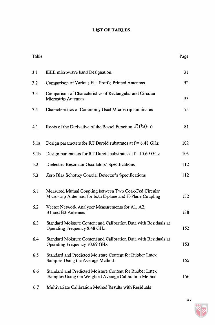
LIST OF TABLES
Table Page
3.1 IEEE microwave band Designation.
3.2 Comparison of Various Flat Profile Printed Antennas
3.3 Comparison of Characteristics of Rectangular and Circular Microstrip Antennas
3.4 Characteristics of Commonly Used Microstrip Laminates
4.1 Roots of the Derivative of the Bessel Function J A (ka) =O
5. l a Design parameters for RT Duroid substrates at f = 8.48 GHz
5.1 b Design parameters for RT Duroid substrates at f = 10.69 GHz
5.2 Dielectric Resonator Oscillators' Specifications
5.3 Zero Bias Schottky Coaxial Detector's Specifications
6.1 Measured Mutual Coupling between Two Coax-Fed Circular Microstrip Antennas, for both E-plane and H-Plane Coupling
6.2 Vector Network Analyzer Measurements for Al, A2, B1 and B2 Antennas
6.3 Standard Moisture Content and Calibration Data with Residuals at Operating Frequency 8.48 GHz
6.4 Standard Moisture Content and Calibration Data with Residuals at Operating Frequency 10.69 GHz
6.5 Standard and Predicted Moisture Content for Rubber Latex Samples Using the Average Method
6.6 Standard and Predicted Moisture Content for Rubber Latex Samples Using the Weighted Average Calibration Method
6.7 Multivariate Calibration Method Results with Residuals
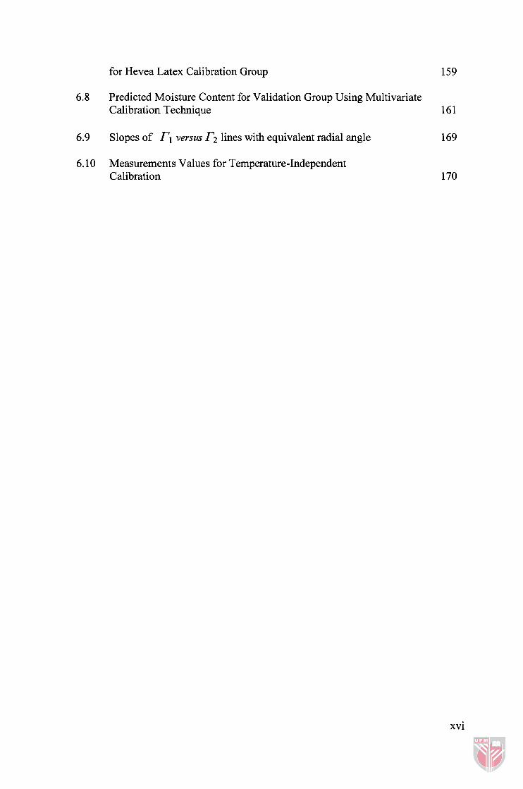
for Hevea Latex Calibration Group
6.8 Predicted Moisture Content for Validation Group Using Multivariate Calibration Technique 161
6.9 Slopes of rl versus r2 lines with equivalent radial angle
6.10 Measurements Values for Temperature-Independent Calibration
xvi
LIST OF FIGURES
Figure Page
2.1 Mechanisms Contributing to the Value of the Effective Loss Factor as a Function of Frequency
2.2 Real and Imaginary Part of the Complex Permittivity, E of Water Plotted versus Frequency
2.3 Complex Dielectric Properties of Hevea Latex as a Function of Frequency, (a) Dielectric Constant, (b) Dielectric Loss Factor
2.4 Complex Dielectric Properties of Hevea Rubber Latex versus MC%, at 0.3 GHz.
2.5 Complex Dielectric Properties of Hevea Rubber Latex versus MC%, at 9.3 GHz
2.6 Complex Dielectric Properties of Hevea Rubber Latex versus Temperature (a) Dielectric Constant, (b) Dielectric Loss Factor
3.1 The Electromagnetic Spectrum
3.2 Antenna as a Transition Device
3.3 Typical Power Pattern Presentation for an Antenna
3.4 Principal E-and H-plane Patterns for a Pyramidal Horn Antenna
3.5 PLF for Transmitting and Receiving Aperture Antennas
3.6 Geometrical Orientations of Transmitting and Receiving Antennas
3.7 Waveguide Antennas (a) E-field Flared Horn and (b) H-field Flared Horn
3.8 Slots in a Waveguide Used as Radiating Antennas
3.9 Coaxial Feed of a Patch Antenna
3.10 Microstrip Line Feed Rectangular Patch Antenna
3.1 1 Aperture-Coupling Feed Patch Antenna
xvii

3.12 Open-Circuit Reflection Terminated by a Semi-Infinite Sample
3.13 Various Measurement Arrangements for Open-Circuit Reflection
3.14 A sample Inserted in a Short-circuited Transmission Line
3.15 Free-Space Reflection Method
3.16 The Setup of Free-space Bi-static Reflection Measurement
3.17 Typical Resonators with Different Coupling Schemes
4.1 Geometry of Circular Microstrip Patch Antenna
4.2 Field Patterns for Circular Microstrip at Resonance Condition
4.3 Fringing Geometry of the Field in Microstrip Antenna
4.4 The Equivalent Parallel RLC Circuit for Microstrip Antenna
4.5 The Geometry of a Propagating Plane Wave in the Positive z Direction Incident on a Plane Interface between Two Regions
4.6 Multiple Reflection and Transmission Propagation Paths for Plane Wave through Different Media
4.7 Free-Space Reflection System Setup
4.8 Signal Flow Graph Representation of the Sensor System as a Cascaded Two-Port Network
5.1 Schematic General Layout of the Sensor System
5.2 Front panel for the Circular Microstrip Antenna Design, proANT
5.3 Schematic Design Proposed for a Single Microstrip Antenna
5.4 Schematic Experimental Setup for Radiation Pattern Measurements 106
5.5 Experimental Setup for Radiation Pattern Measurements in the E-plane and H-plane
5.6 Configuration for Two Circular microstrip antennas, (a) E-plane Coupling and (b) H-plane coupling
5.7 Experimental Setup Diagram for Mutual Coupling Measurements
xviii

5.8 Top and Bottom View of the Sensor Patch.
5.9 Testing Sensor Patch Using HP 8720B Vector Network Analyzer
5.10 Schematic Diagram for the Sensor Patch with Connectors
5.1 1 Various Components Used in the Moisture Meter System
5.12 Schematic Diagram for Electronic Switching Board
6.1 Efficiency vs. Frequency for Different Dielectric substrate Antennas 1 19
6.2 The Total Quality Factor, QT for Three Different Dielectric Substrates 120
6.3 The Gain, G, for the Dielectric Substrates
6.4 The Bandwidth, B W for the Different Dielectric Substrates
6.5a Variation of Radius with Resonant Frequency for Different Dielectric Substrate Antennas (Linear Scale) 124
6.5b Variation of Radius with Resonant Frequency for Different Dielectric Substrate Antennas (Log Scale) 125
6.6 The Variation of Resistance of Circular Microstrip Antenna versus Frequency for the Three Different Substrates atf, = 8.48 GHz
6.7 Reactive Component of the Input Impedance for Circular Microstrip Antenna versus Frequency for Three Different Substrates at f, = 8.48 GHz
6.8 Variation of Resonance Resistance as a Function of Feed Point Location for the substrates at 8.48 GHz
6.9 The Theoretical E&H-Plane Patterns for Circular Microstrip Antenna as Simulated by proANT.
6.10 Experimental E&H-Plane Radiation Power Patterns for Circular Microstrip Antenna with Central Frequency 8.48 GHz
6.1 1 Measured and calculated mutual coupling between the two coax-fed Microstrip antennas, for both E-plane and H-plane coupling
S 11 Parameter (Return Loss) and Smith Chart; for Circular Microstrip Antenna A1 Fabricated on RTD 5880 Laminate with Resonant Frequency of 8.3 88 GHz.
xix
6.13 S22 Parameter (Return Loss) and Smith Chart; for Circular Microstrip Antenna A2 Fabricated on RTD 5880 Laminate with Resonant Frequency of 8.5 1 0 GHz.
6.14 (a) S1 1 for Antenna B 1, (b) Smith Chart for Antenna B 1, (c) SZ2 for Antenna B2 and (d) Smith Chart for Antenna B2 all on RTD 5880.
6.1 5 S 12 Spectrum for (a) Antennas A 1 and A2 and (b) Antennas B 1 and B2, (reflection from semi-Infinite water medium placed 16.5mrn). 139
6.16 Theoretical Normalized Reflected Power versus Water Column Height for Various Perspex Thicknesses 141
6.17 Theoretical and Experimental Reflected Power versus Latex and Water Column Heights. 143
6.18 Normalized reflected power versus the thickness of the Perspex plate 145
6.19 The reflection coefficient Phase versus Perspex Plate thicknesses with Water Column Height of 50 mm at 10.0 GHz 146
6.20 Theoretical Simulation of the Reflected Coefficient Magnitude versus Air layer distances. 147
6.21 Experimental Optimization of Air Distance between Perspex Holder Interface and Transmitting and Receiving Antennas Plane
6.22 Detected Voltages at Receiving Antennas Outputs versus Time
6.23 The Calibration Curve for Moisture Content Measurements of Hevea Latex at Operating Frequency of 8.48 GHz 152
6.24 The Calibration Curve for Moisture Content Measurements of Hevea Latex at Operating Frequency of 1 O.69GHz
6.25 Standard versus Predicted Moisture Content for Rubber Latex Samples Using the Weighted Average Calibration Method 157
6.26 Predicted and Standard Moisture Contents for Rubber Latex Solutions Using Multivariate Regression Calibration Method 160
6.27 Reflected Signal Voltages, TI versus Temperature a t 5 = 8.48 GHz for Different Moisture Content Values of Rubber Latex Samples
6.28 Reflected Signal Voltages T2 versus Temperature atfi = 10.69 GHz for Different Moisture Content Values of Rubber Latex Samples

6.29 Normalized Reflection Ratios versus Temperature for Different Moisture Contents Solutions
6.30 Reflected Signal at 10.69 GHz, r2 versus Reflected Signal at 8.48 GHz, rl for Six Different MC Rubber Latex Solutions in Temp. range of 25°C to 63°C.
6.3 1 Standard Moisture Content versus Averaged Reflected Signal Ratio for Diluted Rubber Latex Solutions 170
6.32 Predicted Moisture Content by Temperature-Independent Calibration versus Oven-Dried Standard Moisture Content 171
6.33 Graphical User Interface of LatexoMeterl, (a) Main Control Panel and (b) System Calibration Panel
6.34 Application of Meter System for Moisture Measurement of Rubber
7.1 Dual Frequency Microstrip Disk Antenna Using Two Planar Strips 181
7.2 Automatic Leveling Circuit Terminated with Transmitting Antenna 182
xxi

LIST OF ABBREVIATIONS
DRO
VCO
VNA
MMIC
DRC
MUT
MC
HPB W
BW
PLF
SEC
SEP
NDT
VSWR
TEM
RF
HF
VHF
UHF
VB
deb.
Dielectric Resonant Oscillator
Voltage Controlled Oscillator
Vector Network Analyzer
Monolithic Microwave Integrated Circuit
Dry Rubber Content
Material Under Test
Moisture Content
Half-Power Beam Width
Bandwidth
Polarization Loss Factor
Standard Error of Calibration
Standard Error of Performance
Non Destructive Testing
Voltage Standing Wave Ratio
Transverse Electric Magnetic Fields
Radio Frequency
High Frequency
Very High Frequency
Ultra High Frequency
Visual Basic
Dry Basis Moisture Content Determination
Wet Basis Moisture Content Determination
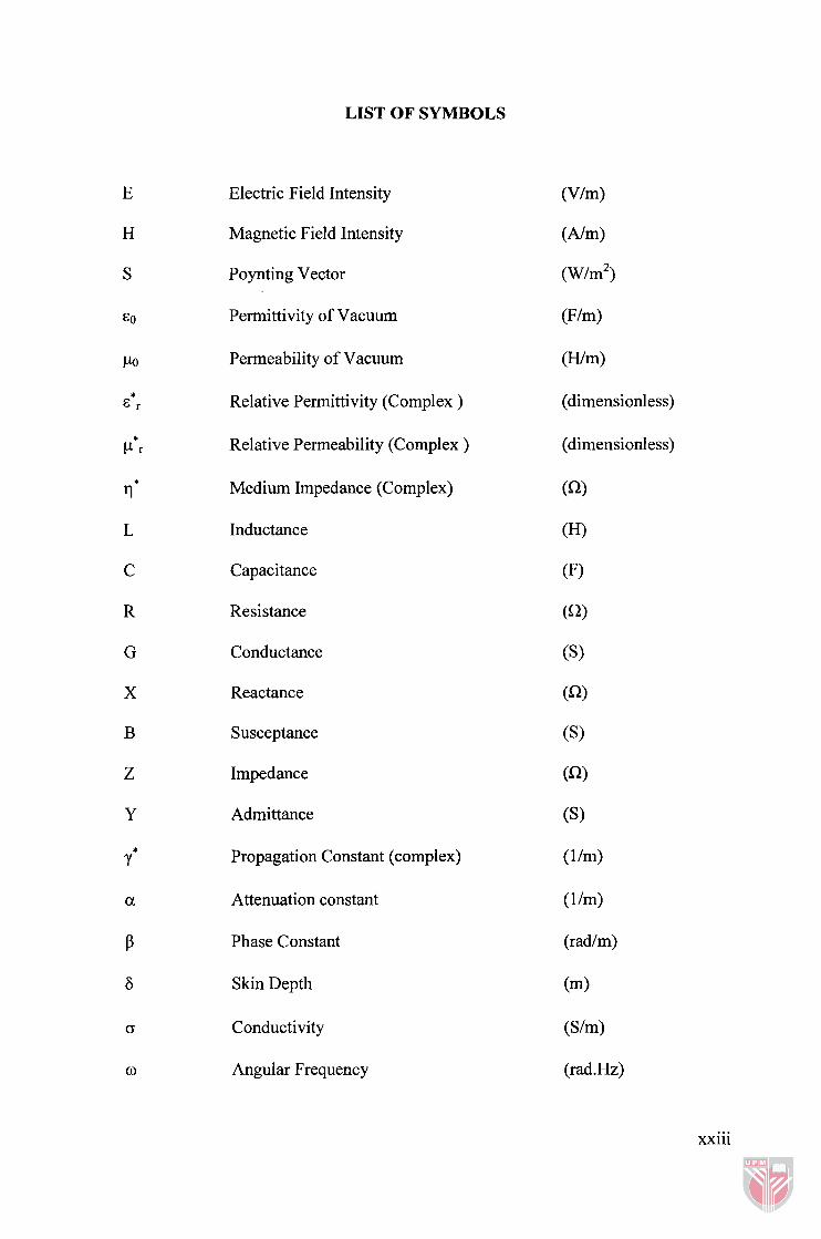
LIST OF SYMBOLS
Electric Field Intensity
Magnetic Field Intensity
Poynting Vector
Permittivity of Vacuum
Permeability of Vacuum
Relative Permittivity (Complex )
Relative Permeability (Complex )
Medium Impedance (Complex)
Inductance
Capacitance
Resistance
Conductance
Reactance
Susceptance
Impedance
Admittance
Propagation Constant (complex)
Attenuation constant
Phase Constant
Skin Depth
Conductivity
Angular Frequency
(dimensionless)
xxiii
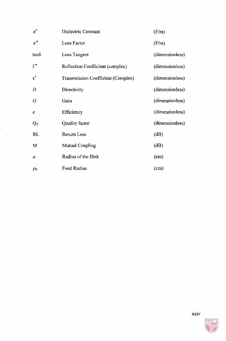
Dielectric Constant
Loss Factor
Loss Tangent
Reflection Coefficient (complex)
Transmission Coefficient (Complex)
Directivity
Gain
Efficiency
Quality factor
Return Loss
Mutual Coupling
Radius of the Disk
Feed Radius
(F/m)
(dimensionless)
(dimensionless)
(dimensionless)
(dimensionless)
(dimensionless)
(dimensionless)
(dimensionless)
(dB)
(dB)
(cm)
(cm)
xxiv
Related Documents