2014 Chevrolet Traverse - AWD | Acadia, Enclave, Traverse VIN R/V Accessory Installation Manual | Accessories | Electrical Accessories | Accessories | Document ID: 3418326 Dual DVD Rear Seat Entertainment Headrest Package Installation Table 1: Kit Contents Table 2: Hardware Bag Contents Table 3: DVD System Wire Description Table 4: Dual DVD Rear Seat Entertainment Headrest Package Installation Installation Instructions Part Number 23139991 Qty Description 2 Headrest Assembly 1 Remote Control 4 Cables 1, 2 (A, B) 2 Cable #3 (A,B) 1 DVD Jumper Harness 1 Metal Wire Puller 1 Owner's Manual 2 IR Headphones 6 AAA Batteries 1 Control Box With Double Back Foam Tape 1 Hardware Bag 1 Installation Instructions 1 Quickstart Guide 4 Clamps 2 T-Tap 4 Head Restraint Guide Kit Contents © 2014 General Motors. All rights reserved. Page 1 of 16 Document ID: 3418326 10/13/2014 https://gsi.ext.gm.com/gsi/showDoc.do?laborOpCode=&docSyskey=3418326&cellId=171560&...

Welcome message from author
This document is posted to help you gain knowledge. Please leave a comment to let me know what you think about it! Share it to your friends and learn new things together.
Transcript

2014 Chevrolet Traverse - AWD | Acadia, Enclave, Traverse VIN R/V Accessory Installation Manual | Accessories |Electrical Accessories | Accessories | Document ID: 3418326
Dual DVD Rear Seat Entertainment Headrest PackageInstallationTable 1: Kit ContentsTable 2: Hardware Bag ContentsTable 3: DVD System Wire DescriptionTable 4: Dual DVD Rear Seat Entertainment Headrest Package Installation
Installation Instructions Part Number
23139991
Qty Description
2 Headrest Assembly
1 Remote Control
4 Cables 1, 2 (A, B)
2 Cable #3 (A,B)
1 DVD Jumper Harness
1 Metal Wire Puller
1 Owner's Manual
2 IR Headphones
6 AAA Batteries
1 Control Box With Double Back Foam Tape
1 Hardware Bag
1 Installation Instructions
1 Quickstart Guide
4 Clamps
2 T-Tap
4 Head Restraint Guide
Kit Contents
© 2014 General Motors. All rights reserved.
Page 1 of 16Document ID: 3418326
10/13/2014https://gsi.ext.gm.com/gsi/showDoc.do?laborOpCode=&docSyskey=3418326&cellId=171560&...
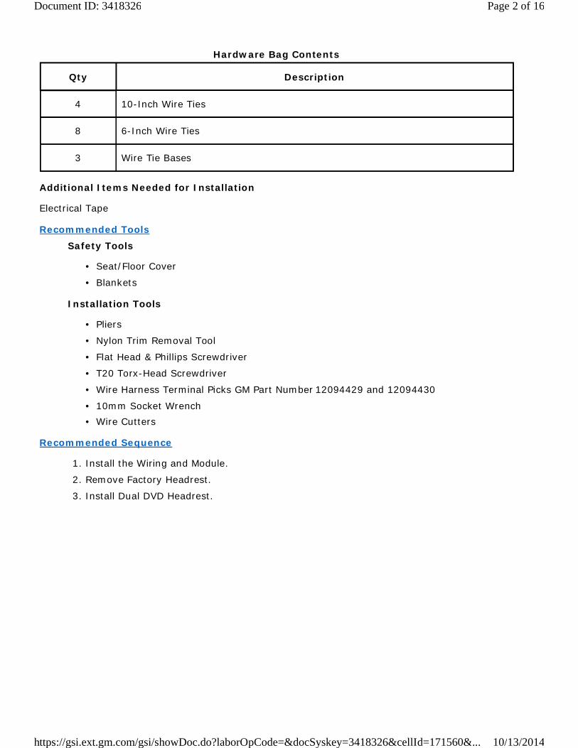
Qty Description
4 10-Inch Wire Ties
8 6-Inch Wire Ties
3 Wire Tie Bases
Hardware Bag Contents
Additional Items Needed for Installation
Electrical Tape
Recommended ToolsSafety Tools
Seat/Floor Cover•
Blankets•
Installation Tools
Pliers•
Nylon Trim Removal Tool•
Flat Head & Phillips Screwdriver•
T20 Torx-Head Screwdriver•
Wire Harness Terminal Picks GM Part Number 12094429 and 12094430•
10mm Socket Wrench•Wire Cutters•
Recommended Sequence
1. Install the Wiring and Module.
2. Remove Factory Headrest.
3. Install Dual DVD Headrest.
Page 2 of 16Document ID: 3418326
10/13/2014https://gsi.ext.gm.com/gsi/showDoc.do?laborOpCode=&docSyskey=3418326&cellId=171560&...

Callout Description
1 Signal Cable 1A
2 Signal Cable 2A
3 FM Antenna Cable
4 Signal Input (White)
5 Signal Input (Blue)
6 Control Box
7 Signal Cable 1B
8 Signal Cable 2B
9 Signal Cable 3B
10 Signal Out (Black)
DVD System Wire Description
Page 3 of 16Document ID: 3418326
10/13/2014https://gsi.ext.gm.com/gsi/showDoc.do?laborOpCode=&docSyskey=3418326&cellId=171560&...
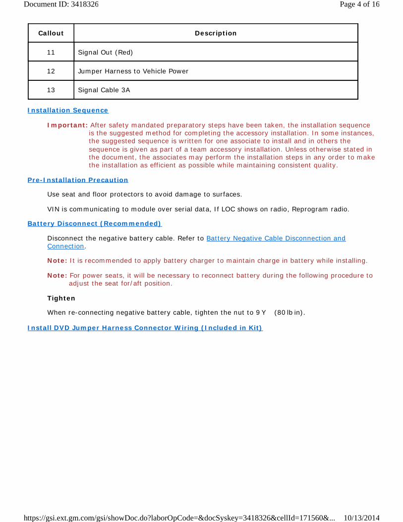
Callout Description
11 Signal Out (Red)
12 Jumper Harness to Vehicle Power
13 Signal Cable 3A
Installation Sequence
Important: After safety mandated preparatory steps have been taken, the installation sequenceis the suggested method for completing the accessory installation. In some instances,the suggested sequence is written for one associate to install and in others thesequence is given as part of a team accessory installation. Unless otherwise stated inthe document, the associates may perform the installation steps in any order to makethe installation as efficient as possible while maintaining consistent quality.
Pre-Installation Precaution
Use seat and floor protectors to avoid damage to surfaces.
VIN is communicating to module over serial data, If LOC shows on radio, Reprogram radio.
Battery Disconnect (Recommended)
Disconnect the negative battery cable. Refer to Battery Negative Cable Disconnection andConnection.
Note: It is recommended to apply battery charger to maintain charge in battery while installing.
Note: For power seats, it will be necessary to reconnect battery during the following procedure toadjust the seat for/aft position.
Tighten
When re-connecting negative battery cable, tighten the nut to 9Y (80 lb in).
Install DVD Jumper Harness Connector Wiring (Included in Kit)
Page 4 of 16Document ID: 3418326
10/13/2014https://gsi.ext.gm.com/gsi/showDoc.do?laborOpCode=&docSyskey=3418326&cellId=171560&...
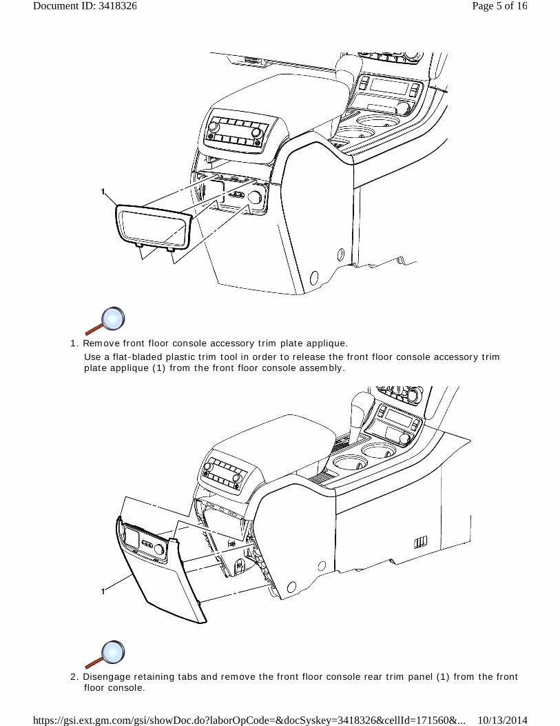
1. Remove front floor console accessory trim plate applique.Use a flat-bladed plastic trim tool in order to release the front floor console accessory trimplate applique (1) from the front floor console assembly.
2. Disengage retaining tabs and remove the front floor console rear trim panel (1) from the frontfloor console.
Page 5 of 16Document ID: 3418326
10/13/2014https://gsi.ext.gm.com/gsi/showDoc.do?laborOpCode=&docSyskey=3418326&cellId=171560&...
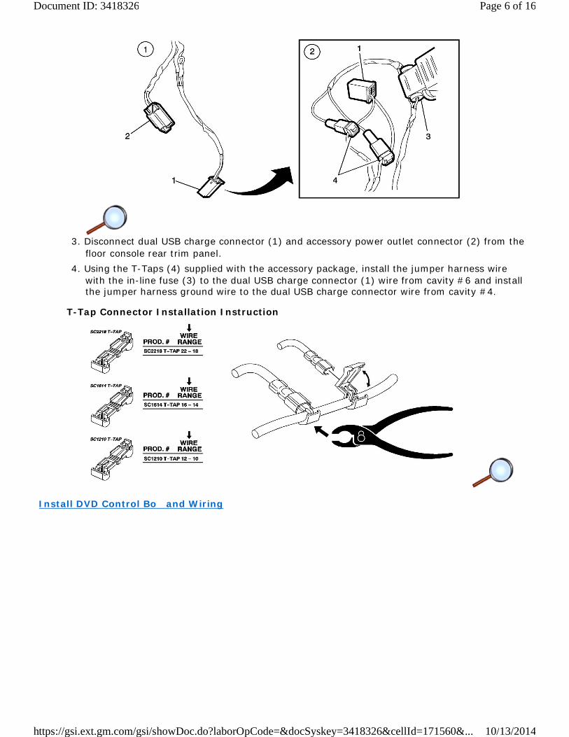
3. Disconnect dual USB charge connector (1) and accessory power outlet connector (2) from thefloor console rear trim panel.
4. Using the T-Taps (4) supplied with the accessory package, install the jumper harness wirewith the in-line fuse (3) to the dual USB charge connector (1) wire from cavity #6 and installthe jumper harness ground wire to the dual USB charge connector wire from cavity #4.
T-Tap Connector Installation Instruction
Install DVD Control Bo and Wiring
Page 6 of 16Document ID: 3418326
10/13/2014https://gsi.ext.gm.com/gsi/showDoc.do?laborOpCode=&docSyskey=3418326&cellId=171560&...
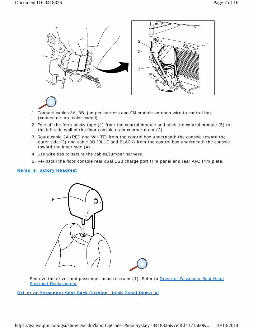
1. Connect cables 3A, 3B, jumper harness and FM module antenna wire to control box(connectors are color coded).
2. Peel off the form sticky tape (1) from the control module and stick the control module (5) tothe left side wall of the floor console main compartment (2).
3. Route cable 3A (RED and WHITE) from the control box underneath the console toward theouter side (3) and cable 3B (BLUE and BLACK) from the control box underneath the consoletoward the inner side (4).
4. Use wire ties to secure the cables/jumper harness.
5. Re-install the floor console rear dual USB charge port trim panel and rear APO trim plate.
Remo e actory Headrest
Remove the driver and passenger head restraint (1). Refer to Driver or Passenger Seat HeadRestraint Replacement.
Dri er or Passenger Seat Back Cushion inish Panel Remo al
Page 7 of 16Document ID: 3418326
10/13/2014https://gsi.ext.gm.com/gsi/showDoc.do?laborOpCode=&docSyskey=3418326&cellId=171560&...

Remove the driver and passenger front seat cushion finish panel (1). Refer to Front Seat BackCushion Finish Panel Replacement.
Remo e and Replace Head Restraint uide
Remove and replace the driver and passenger head restraint guides (1) with supplied headrestraint guides with accessory package. Refer to Driver or Passenger Seat Head Restraint GuideReplacement.
Install Video HeadrestDri er and Passenger DVD Headrest Identification
The cable with RED/WHITE connector ends is Driver DVD headrest.
The cable with BLUE/BLACK connector ends is Passenger DVD headrest.
Page 8 of 16Document ID: 3418326
10/13/2014https://gsi.ext.gm.com/gsi/showDoc.do?laborOpCode=&docSyskey=3418326&cellId=171560&...

1. Insert cables 1A (1) and 2A (3) into holes at top of driver seat (2).
2. Install DVD headrest (1) and keep headrest in the up most position.
Page 9 of 16Document ID: 3418326
10/13/2014https://gsi.ext.gm.com/gsi/showDoc.do?laborOpCode=&docSyskey=3418326&cellId=171560&...
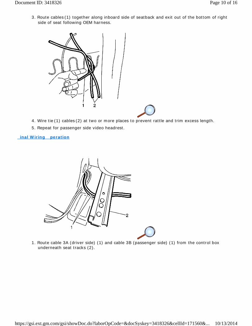
3. Route cables (1) together along inboard side of seatback and exit out of the bottom of rightside of seat following OEM harness.
4. Wire tie (1) cables (2) at two or more places to prevent rattle and trim excess length.
5. Repeat for passenger side video headrest.
inal Wiring peration
1. Route cable 3A (driver side) (1) and cable 3B (passenger side) (1) from the control boxunderneath seat tracks (2).
Page 10 of 16Document ID: 3418326
10/13/2014https://gsi.ext.gm.com/gsi/showDoc.do?laborOpCode=&docSyskey=3418326&cellId=171560&...
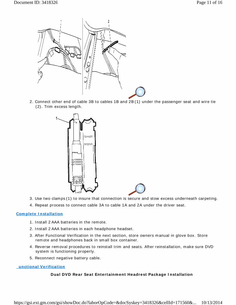
2. Connect other end of cable 3B to cables 1B and 2B (1) under the passenger seat and wire tie(2). Trim excess length.
3. Use two clamps (1) to insure that connection is secure and stow excess underneath carpeting.
4. Repeat process to connect cable 3A to cable 1A and 2A under the driver seat.
Complete Installation
1. Install 2 AAA batteries in the remote.
2. Install 2 AAA batteries in each headphone headset.
3. After Functional Verification in the next section, store owners manual in glove box. Storeremote and headphones back in small box container.
4. Reverse removal procedures to reinstall trim and seats. After reinstallation, make sure DVDsystem is functioning properly.
5. Reconnect negative battery cable.
unctional Verification
Dual DVD Rear Seat Entertainment Headrest Package Installation
Page 11 of 16Document ID: 3418326
10/13/2014https://gsi.ext.gm.com/gsi/showDoc.do?laborOpCode=&docSyskey=3418326&cellId=171560&...
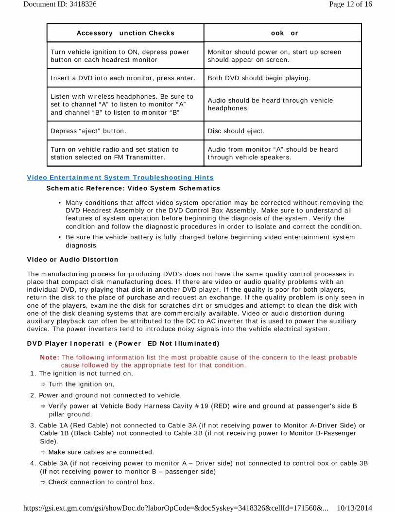
Accessory unction Checks ook or
Turn vehicle ignition to ON, depress powerbutton on each headrest monitor
Monitor should power on, start up screenshould appear on screen.
Insert a DVD into each monitor, press enter. Both DVD should begin playing.
Listen with wireless headphones. Be sure toset to channel “A” to listen to monitor “A”and channel “B” to listen to monitor “B”
Audio should be heard through vehicleheadphones.
Depress “eject” button. Disc should eject.
Turn on vehicle radio and set station tostation selected on FM Transmitter.
Audio from monitor “A” should be heardthrough vehicle speakers.
Video Entertainment System Troubleshooting HintsSchematic Reference: Video System Schematics
Many conditions that affect video system operation may be corrected without removing theDVD Headrest Assembly or the DVD Control Box Assembly. Make sure to understand allfeatures of system operation before beginning the diagnosis of the system. Verify thecondition and follow the diagnostic procedures in order to isolate and correct the condition.
•
Be sure the vehicle battery is fully charged before beginning video entertainment systemdiagnosis.
•
Video or Audio Distortion
The manufacturing process for producing DVD's does not have the same quality control processes inplace that compact disk manufacturing does. If there are video or audio quality problems with anindividual DVD, try playing that disk in another DVD player. If the quality is poor for both players,return the disk to the place of purchase and request an exchange. If the quality problem is only seen inone of the players, examine the disk for scratches dirt or smudges and attempt to clean the disk withone of the disk cleaning systems that are commercially available. Video or audio distortion duringauxiliary playback can often be attributed to the DC to AC inverter that is used to power the auxiliarydevice. The power inverters tend to introduce noisy signals into the vehicle electrical system.
DVD Player Inoperati e (Power ED Not Illuminated)
Note: The following information list the most probable cause of the concern to the least probablecause followed by the appropriate test for that condition.
1. The ignition is not turned on.Turn the ignition on.
2. Power and ground not connected to vehicle.Verify power at Vehicle Body Harness Cavity #19 (RED) wire and ground at passenger's side Bpillar ground.
3. Cable 1A (Red Cable) not connected to Cable 3A (if not receiving power to Monitor A-Driver Side) orCable 1B (Black Cable) not connected to Cable 3B (if not receiving power to Monitor B-PassengerSide).
Make sure cables are connected.
4. Cable 3A (if not receiving power to monitor A – Driver side) not connected to control box or cable 3B(if not receiving power to monitor B – passenger side)
Check connection to control box.
Page 12 of 16Document ID: 3418326
10/13/2014https://gsi.ext.gm.com/gsi/showDoc.do?laborOpCode=&docSyskey=3418326&cellId=171560&...

5. Jumper Harness is not connected to Control Box.Verify connection to DVD Control Box. Check for power at end of Jumper Harness (whiteconnector 3–way) at Control Box. If no power at Control Box, check the fuse and the relay on theJumper Harness. If no power at Control Box, check power at vehicle body harness cavity #19(RED) wire. of power at control box – replace the control box.
6. Remove monitor that is not receiving power.Check power at Red Connector (Monitor A-Driver Side) or power at Black Connector (Monitor B-Passenger Side) or power at BLACK connector (monitor B – passenger side). Circuits are locatedat cavity 5 and 6 (RED and BLACK wires are adjacent to each other). If power and ground areverified at connectors, replace the DVD Electronics (Monitor). Refer to DVD ElectronicsReplacement.
7. DVD Electronics inoperative.Replace the DVD Electronics. Refer to DVD Electronics Replacement.
DVD Player Inoperati e (Power ED Illuminated)
Note: The following lists the most probable cause of the concern to the least probable causefollowed by the appropriate test for that condition.
1. The DVD Player is not turned on.Press the Power Button to turn unit on.
2. Press the play button.If no disc in unit, NO DISC message appears on display.
3. Insert Disc. If unit does not accept disc.Replace DVD Electronics. Refer to DVD Electronics Replacement.
DVD Display Inoperati e ( EDs Illuminate but No Video)
Note: The following lists the most probable cause of the concern to the least probable causefollowed by the appropriate test for that condition.
Note: Inspect the DVD wires for damage at the connectors (control box end and monitor end). If3A or 3B wires are damaged, replace the cables only. If the headrest wires are damage,replace the headrest only and not the monitor.
1. Verify that the correct source is selected.Monitor A or Monitor B should appear in the upper right hand corner of display.
2. Cable 2A (White Cable) not connected to Cable 3A (if no display on Monitor A-Driver Side) or Cable2B (Blue Cable) not connected to Cable 3B (if no display on Monitor B-Passenger Side).
Make sure cables are connected.
3. Cable 3A (if not receiving power to Monitor A-Driver Side) or Cable 3B (if not receiving power toMonitor B-Passenger Side).
Cables not connected to Control Box.
4. Remove monitor that is not receiving video.Verify that connectors are connected to the Monitor. If no video is displayed, replace the DVDElectronics (Monitor). Refer to DVD Electronics Replacement.
Cannot Hear Audio Through Vehicle Speakers ( M Modulation Inoperati e)
Note: The following lists the most probable cause of the concern to the least probable causefollowed by the appropriate test for that condition.
1. FM Transmitter not turned on.Turn on the FM Transmitter using the Remote Control. Press the DVD Button (A) on the RemoteControl to control Monitor A-Driver Side Headrest. Press the Sound Around On/Off Button. “CHOn” should appear on Monitor A display.
Page 13 of 16Document ID: 3418326
10/13/2014https://gsi.ext.gm.com/gsi/showDoc.do?laborOpCode=&docSyskey=3418326&cellId=171560&...
2. Radio and DVD Unit are not set to the same FM Frequency.Press the Sound Around Select button to select a frequency (88.3 MHz, 88.7 MHz, 89.1 MHz, 89.5MHz, 89.9 MHz, or 90.3 MHz). The frequency should appear on Monitor A display in the upperright hand corner. Tune the radio to the frequency selected. If no DVD audio over speakers,verify audio by selection another radio frequency. If no DVD audio over speakers, replace theDVD Control Box.
Video Entertainment System Wireless Headphone Inoperati e
Note: The following lists the most probable cause of the concern to the least probable causefollowed by the appropriate test for that condition.
1. Volume control on the wireless headphone set is turned all the way down.Adjust the volume control on the headphones.
2. Incorrect channel selected.To hear audio from Monitor A-Driver Side, select Channel A. To hear audio from Monitor B-Passenger Side, select Channel B.
3. Dead batteries or batteries placed incorrectly in the wireless headphone set.Turn on power the headphone set. If the headset indicator does not turn on, place batteries incorrectly or replace the batteries in the headset as needed.
4. Make sure headphone is in line of sight and no obstructions of the Monitor being listened from.
5. Faulty headphone set.Test the operation of the system using a known good headphone set. If operation is OK, replacethe faulty headphone set.
6. Inoperative infra-red transmitter in the (DVD Monitor (s).Replace the DVD Electronics. Refer to DVD Electronics Replacement.
Video Entertainment System Remote Control Inoperati e
Note: The following lists the most probable cause of the concern to the least probable cause followedby the appropriate test for that condition.
The buttons on the video remote control do not operate the video disc player, but the buttons on theDVD Headrest Monitor Control Panel operate normally.
Press DVD A button to control Monitor A or press DVD B button to control Monitor B.
Dead batteries or batteries placed incorrectly in the video remote control. Place batteries incorrectly or replace the dead batteries as needed.Faulty remote control. Test the operation of the system using a known good remote control. Ifoperation is OK, replace the faulty remote control.Inoperative infrared transmitter in the (DVD) Monitor (s). Replace the DVD Electronics.
DVD Electronics Replacement
Page 14 of 16Document ID: 3418326
10/13/2014https://gsi.ext.gm.com/gsi/showDoc.do?laborOpCode=&docSyskey=3418326&cellId=171560&...
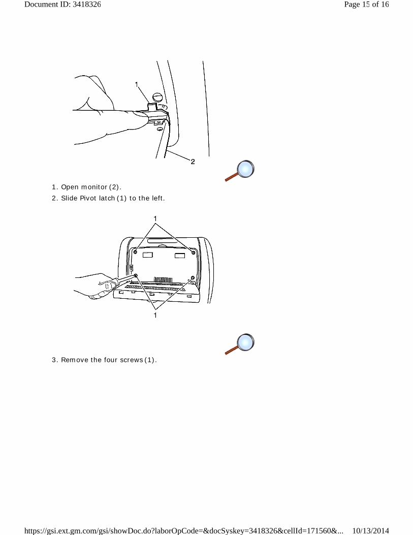
1. Open monitor (2).2. Slide Pivot latch (1) to the left.
3. Remove the four screws (1).
Page 15 of 16Document ID: 3418326
10/13/2014https://gsi.ext.gm.com/gsi/showDoc.do?laborOpCode=&docSyskey=3418326&cellId=171560&...

4. Partially remove the monitor (1) from the headrest (2).
5. Depress release and remove the electrical connectors (1).
6. Remove monitor (2) from headrest.
7. Reverse steps 1 - 6 to install new monitor.
Page 16 of 16Document ID: 3418326
10/13/2014https://gsi.ext.gm.com/gsi/showDoc.do?laborOpCode=&docSyskey=3418326&cellId=171560&...
Related Documents