1999 GMC Truck GMC K Pickup - 4WD | Escalade, Pickup Classic, Suburban, Tahoe, Yukon VIN C/K Service Manual | Document ID: 559515 DTC P0370 Timing Reference High Resolution System Performance Circuit Description The optical sensor provides a high resolution signal to the PCM by counting pulses on the sensor disk located in the injection pump. The high resolution is one of the most important inputs by the PCM for fuel control and timing. This test monitors the number of high resolution pulses which have been missed (not detected). It's based on a comparison between the number of pulses that were detected since the last pump cam pulse and the number of the pulses that should have occurred. There are approximately 64 high resolution pulses for every cam pulse. Conditions for Running the DTC The engine is operating. Conditions for Setting the DTC A number of high resolution pulses missing (internal to PCM (64 to 1 ratio) per every 8 cam reference pulses. Action Taken When the DTC Sets © 2015 General Motors. All rights reserved. Page 1 of 6 Document ID: 559515 8/29/2015 https://gsi.ext.gm.com/gsi/showDoc.do?docSyskey=559515&cellId=33783&pubObjSyskey=3236...

Welcome message from author
This document is posted to help you gain knowledge. Please leave a comment to let me know what you think about it! Share it to your friends and learn new things together.
Transcript
1999 GMC Truck GMC K Pickup - 4WD | Escalade, Pickup Classic, Suburban, Tahoe, Yukon VIN C/K Service Manual | Document ID: 559515
DTC P0370 Timing Reference High Resolution System Performance
Circuit Description
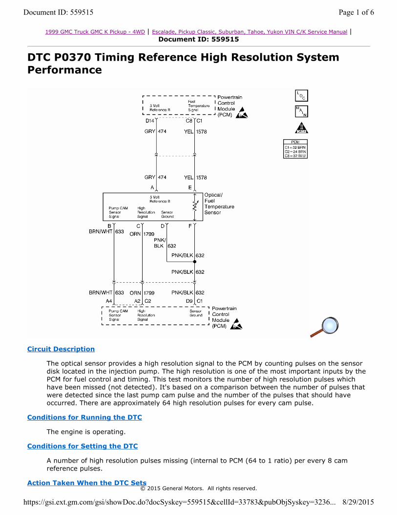
The optical sensor provides a high resolution signal to the PCM by counting pulses on the sensor disk located in the injection pump. The high resolution is one of the most important inputs by the PCM for fuel control and timing. This test monitors the number of high resolution pulses which have been missed (not detected). It's based on a comparison between the number of pulses that were detected since the last pump cam pulse and the number of the pulses that should have occurred. There are approximately 64 high resolution pulses for every cam pulse.
Conditions for Running the DTC
The engine is operating.
Conditions for Setting the DTC
A number of high resolution pulses missing (internal to PCM (64 to 1 ratio) per every 8 cam reference pulses.
Action Taken When the DTC Sets© 2015 General Motors. All rights reserved.
Page 1 of 6Document ID: 559515
8/29/2015https://gsi.ext.gm.com/gsi/showDoc.do?docSyskey=559515&cellId=33783&pubObjSyskey=3236...

• The PCM illuminates the malfunction indicator lamp (MIL) on the first consecutive drive trip that the diagnostic runs and fails.
• The Freeze Frame records the operating conditions at the time of failure and updates the Failure Records.
• The PCM will activate back up fuel.
Conditions for Clearing the MIL/DTC
• The PCM will turn the MIL off after three consecutive trips without a fault condition.
• A History DTC clears after forty consecutive warm-up cycles, if this or any other emission related diagnostic does not report any failures
• The use of a scan tool.
Diagnostic Aids
• Intermittent DTCs P0251, P0370 and P1216 may be caused by air entering the fuel system when fuel levels get below 1/8 of a tank while performing hard acceleration or turning maneuvers. DTC P0251, P0370 and P1216 may set if the vehicle has run out of fuel. Customer driving habits should be checked to determine if the vehicle has been performing in these manners. If the vehicle has been performing under these conditions, bleed the fuel system of all air and test drive the vehicle.
• Intermittent DTC P0370 may be caused by contaminated fuel. Inspect a fuel sample from the return line at the injection pump for any type of foreign materials. Place a fuel sample in a dark colored container. Using a bright light, inspect for fine reflective contaminates. If contamination is found, clean the fuel system and replace the fuel filter.
• When PCM is in backup fuel, fast idle and poor performance problems will exist. If DTCP0251 is also stored, the snap shot mode on the scan tool should be used in order to properly identify a malfunction. DTCs P0335, P1216, and P1217 may set along with this DTC.
• The least likely cause of failure is the PCM.
Test Description
Number(s) below refer to the step number(s) on the Diagnostic Table.
2. This step will determine if the 5 volt reference is present. 3. This step checks the ground circuit.4. This step determines if the problem is currently active by the scan tool displaying Last Test
Failed. Do not proceed any further with this table if the scan tool does not display the term Last Test Failed. Duplicating the conditions in Freeze Frame and Failure Records can help create an active fault.
5. This step determines if a High Res signal is being sent to the PCM. Refer to the RPM vs Hertz table to compare the Hertz readings at different RPMs. Using Freeze Frame and Failure Records will help identify the RPM the problem occurs.
9. The PCM supplies 5 volts on the signal circuit. This step determines if that voltage is present, not present, or too much voltage is present.
13. This step determines if the signal circuit is shorted to 5 V. A normal high res signal circuit will have 3–5 mA. Any reading over 50 mA indicates a short to 5 V.
DTC P0370 Timing Reference High Resolution System Performance
Step Action Value(s) Yes No
1 Important: Before clearing any DTCs, use the scan tool Capture Info to save freeze frame and failure records for reference, as the
— Go to Step 2
Go to Powertrain On Board Diagnostic
Page 2 of 6Document ID: 559515
8/29/2015https://gsi.ext.gm.com/gsi/showDoc.do?docSyskey=559515&cellId=33783&pubObjSyskey=3236...
Step Action Value(s) Yes No
scan tool loses data when using the Clear Info function.
Was the Powertrain On–Board Diagnostic (OBD) System Check performed?
(OBD) System Check
2
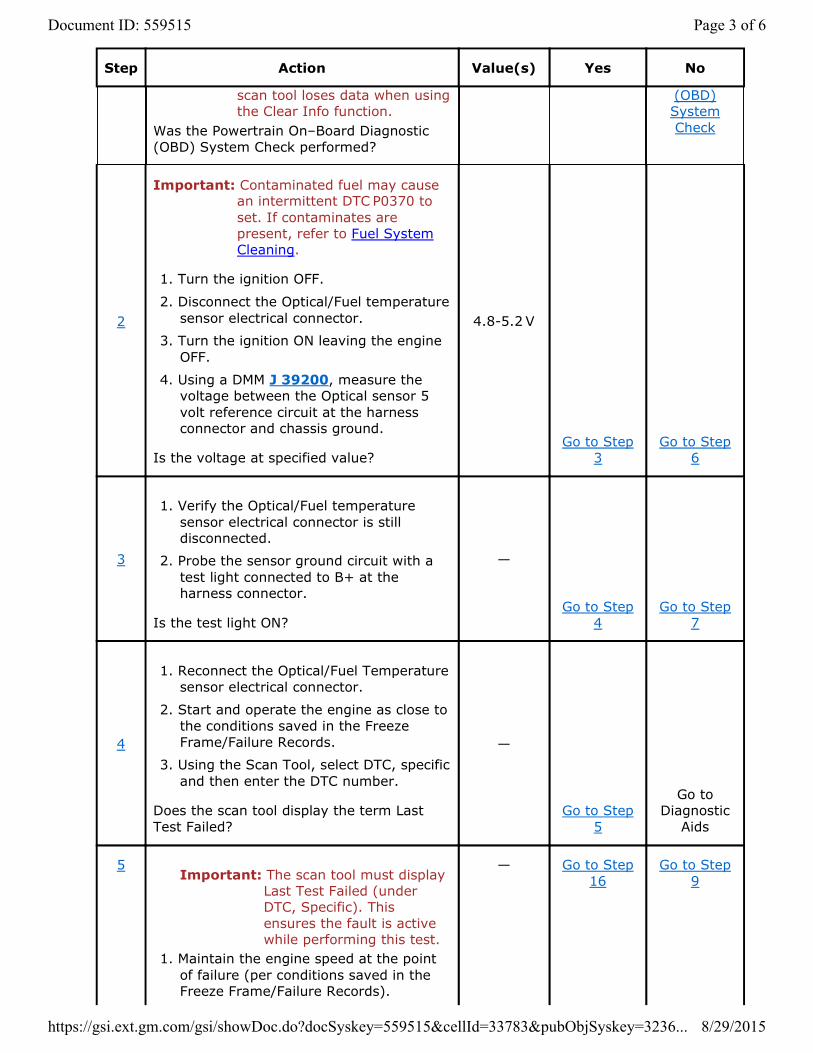
Important: Contaminated fuel may cause an intermittent DTC P0370 to set. If contaminates are present, refer to Fuel System Cleaning.
1. Turn the ignition OFF.
2. Disconnect the Optical/Fuel temperature sensor electrical connector.
3. Turn the ignition ON leaving the engine OFF.
4. Using a DMM J 39200, measure the voltage between the Optical sensor 5volt reference circuit at the harness connector and chassis ground.
Is the voltage at specified value?
4.8-5.2 V
Go to Step 3
Go to Step 6
3
1. Verify the Optical/Fuel temperature sensor electrical connector is still disconnected.
2. Probe the sensor ground circuit with a test light connected to B+ at the harness connector.
Is the test light ON?
—
Go to Step 4
Go to Step 7
4
1. Reconnect the Optical/Fuel Temperature sensor electrical connector.
2. Start and operate the engine as close to the conditions saved in the Freeze Frame/Failure Records.
3. Using the Scan Tool, select DTC, specific and then enter the DTC number.
Does the scan tool display the term Last Test Failed?
—
Go to Step 5
Go to Diagnostic
Aids
5Important: The scan tool must display
Last Test Failed (under DTC, Specific). This ensures the fault is active while performing this test.
1. Maintain the engine speed at the point of failure (per conditions saved in the Freeze Frame/Failure Records).
— Go to Step 16
Go to Step 9
Page 3 of 6Document ID: 559515
8/29/2015https://gsi.ext.gm.com/gsi/showDoc.do?docSyskey=559515&cellId=33783&pubObjSyskey=3236...
Step Action Value(s) Yes No
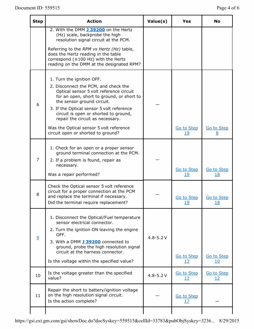
2. With the DMM J 39200 on the Hertz (Hz) scale, backprobe the high resolution signal circuit at the PCM.
Referring to the RPM vs Hertz (Hz) table, does the Hertz reading in the table correspond (±100 Hz) with the Hertz reading on the DMM at the designated RPM?
6
1. Turn the ignition OFF.
2. Disconnect the PCM, and check the Optical sensor 5 volt reference circuit for an open, short to ground, or short to the sensor ground circuit.
3. If the Optical sensor 5 volt reference circuit is open or shorted to ground, repair the circuit as necessary.
Was the Optical sensor 5 volt reference circuit open or shorted to ground?
—
Go to Step 19
Go to Step 8
7
1. Check for an open or a proper sensor ground terminal connection at the PCM.
2. If a problem is found, repair as necessary.
Was a repair performed?
—
Go to Step 19
Go to Step 18
8
Check the Optical sensor 5 volt reference circuit for a proper connection at the PCM and replace the terminal if necessary. Did the terminal require replacement?
—Go to Step
19Go to Step
18
9
1. Disconnect the Optical/Fuel temperature sensor electrical connector.
2. Turn the ignition ON leaving the engine OFF.
3. With a DMM J 39200 connected to ground, probe the high resolution signal circuit at the harness connector.
Is the voltage within the specified value?
4.8-5.2 V
Go to Step 13
Go to Step 10
10 Is the voltage greater than the specified value? 4.8-5.2 V Go to Step
11Go to Step
12
11Repair the short to battery/ignition voltage on the high resolution signal circuit. Is the action complete?
— Go to Step 17 —
Page 4 of 6Document ID: 559515
8/29/2015https://gsi.ext.gm.com/gsi/showDoc.do?docSyskey=559515&cellId=33783&pubObjSyskey=3236...
Step Action Value(s) Yes No
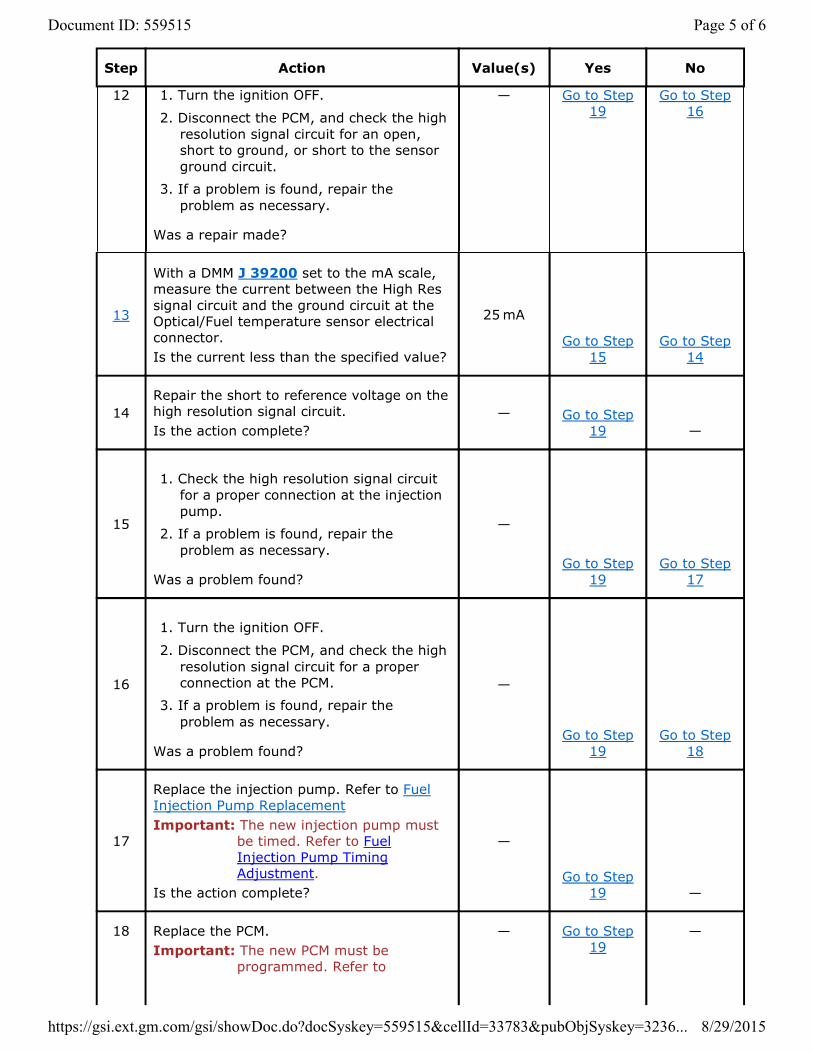
12 1. Turn the ignition OFF.
2. Disconnect the PCM, and check the high resolution signal circuit for an open, short to ground, or short to the sensor ground circuit.
3. If a problem is found, repair the problem as necessary.
Was a repair made?
— Go to Step 19
Go to Step 16
13
With a DMM J 39200 set to the mA scale, measure the current between the High Res signal circuit and the ground circuit at the Optical/Fuel temperature sensor electrical connector. Is the current less than the specified value?
25 mA
Go to Step 15
Go to Step 14
14Repair the short to reference voltage on the high resolution signal circuit. Is the action complete?
— Go to Step 19 —
15
1. Check the high resolution signal circuit for a proper connection at the injection pump.
2. If a problem is found, repair the problem as necessary.
Was a problem found?
—
Go to Step 19
Go to Step 17
16
1. Turn the ignition OFF.
2. Disconnect the PCM, and check the high resolution signal circuit for a proper connection at the PCM.
3. If a problem is found, repair the problem as necessary.
Was a problem found?
—
Go to Step 19
Go to Step 18
17
Replace the injection pump. Refer to Fuel Injection Pump ReplacementImportant: The new injection pump must
be timed. Refer to Fuel Injection Pump Timing Adjustment.
Is the action complete?
—
Go to Step 19 —
18 Replace the PCM.Important: The new PCM must be
programmed. Refer to
— Go to Step 19
—
Page 5 of 6Document ID: 559515
8/29/2015https://gsi.ext.gm.com/gsi/showDoc.do?docSyskey=559515&cellId=33783&pubObjSyskey=3236...

Step Action Value(s) Yes No
Powertrain Control Module Replacement/Programming.
Is the action complete?
19
1. Using the Scan Tool, clear the DTCs.
2. Start the engine and idle at normal operating temperature.
3. Select DTC, Specific, then enter the DTC number which was set.
4. Operate the vehicle, within the Conditions for Setting this DTC, until the Scan Tool indicates the diagnostic Ran.
Does the Scan Tool indicate the diagnostic Passed?
—
Go to Step 20
Go to Step 2
20Does the Scan Tool display any additional undiagnosed DTCs? —
Go to the Applicable DTC Table System OK
Page 6 of 6Document ID: 559515
8/29/2015https://gsi.ext.gm.com/gsi/showDoc.do?docSyskey=559515&cellId=33783&pubObjSyskey=3236...
Related Documents