Catalog 2006 • dSPACE • Technologiepark 25 • 33100 Paderborn • Germany • [email protected] • www.dspace.com 48 Function Prototyping 2006 dSPACE Prototyping Systems Accelerated function prototyping for controller development Control design development and optimization without manual programming Optimum scalability and flexibility of dSPACE hardware with high performance and extensive I/O MATLAB ® /Simulink ® models implemented on dSPACE hardware automatically with dSPACE Real-Time Interface Whole controller replaced by a dSPACE prototyping system, or new functions developed via bypassing Flexible adaptation of sensor and actuator signals with RapidPro Hardware Key Features Introduction dSPACE prototyping systems are flexible development systems that let you develop and optimize your control designs for the real plant without manual programming. Design faults are found immediately and corrections can be carried out on-the-spot. No special expertise is necessary for implementation on the prototyping system. We offer numerous input/output interfaces to connect the prototyping system to sensors and actuators. These can be configured graphically in the block diagram, without any programming. dSPACE has a wide range of software and hardware components for building your own tailored prototyping system. You can also take advantage of our engineering service to make customer-specific extensions. Two Ways of Function Prototyping There are two basic approaches to rapid control prototyping (RCP): fullpass and bypass. With fullpass, the prototyping system completely replaces the production ECU. All sensors and actuators are connected to this real-time hardware, and it has full authority to control the plant. In bypassing (see also p.50), the prototyping system may be connected to some extra sensors and actuators, and parts of the control task are done by a production controller. For example, specific software functions that are under development are offloaded from the production controller to the controller prototyping unit connected to it.

Welcome message from author
This document is posted to help you gain knowledge. Please leave a comment to let me know what you think about it! Share it to your friends and learn new things together.
Transcript

Catalog 2006 • dSPACE • Technologiepark 25 • 33100 Paderborn • Germany • [email protected] • www.dspace.com
48
Function Prototyping
2006
dSPACE Prototyping Systems
Accelerated function prototyping for controller development
Control design development and optimization without manual programming
Optimum scalability and flexibility of dSPACE hardware with high performance and extensive I/O
MATLAB®/Simulink® models implemented on dSPACE hardware automatically with dSPACE Real-Time Interface
Whole controller replaced by a dSPACE prototyping system, or new functions developed via bypassing
Flexible adaptation of sensor and actuator signals with RapidPro Hardware
Key Features
Introduction dSPACE prototyping systems are flexible development systems that let you develop
and optimize your control designs for the real plant without manual programming.
Design faults are found immediately and corrections can be carried out on-the-spot.
No special expertise is necessary for implementation on the prototyping system.
We offer numerous input/output interfaces to connect the prototyping system to
sensors and actuators. These can be configured graphically in the block diagram,
without any programming.
dSPACE has a wide range of software and hardware components for building your
own tailored prototyping system. You can also take advantage of our engineering
service to make customer-specific extensions.
Two Ways of Function Prototyping
There are two basic approaches to rapid control prototyping (RCP): fullpass and bypass.
With fullpass, the prototyping system completely replaces the production ECU.
All sensors and actuators are connected to this real-time hardware, and it has full
authority to control the plant.
In bypassing (see also p.50), the prototyping system may be connected to some extra
sensors and actuators, and parts of the control task are done by a production controller.
For example, specific software functions that are under development are offloaded
from the production controller to the controller prototyping unit connected to it.

Catalog 2006 • dSPACE • Technologiepark 25 • 33100 Paderborn • Germany • [email protected] • www.dspace.com 2006
49
dSPACE Prototyping Systems
Application Areas
Automotive IndustryThe flexible development systems let you go on optimizing your function designs
in the vehicle until you have them just right. Design faults are found immediately,
and corrections can be carried out on the spot. Whatever the ECU will be used for –
engine, transmission, vehicle dynamics, airbags, comfort systems or any other type
of application – the prototyping system handles it.
Aerospace IndustryThe prototyping systems provide all you need for
prototyping the software for your production con-
trollers and can be used for applications such as:
Helicopter blade control for noise reduction
Realistic simulation of flight maneuvers
Control of combustion pressure oscillations
Turbine development
Other IndustriesThe prototyping systems have been used for
many different applications, such as:
Control of a modular rail system
for passenger and freight transport
Control of a telescope
Control system for a wrist simulator
Control of the dragline cycle in open
cut mining

Catalog 2006 • dSPACE • Technologiepark 25 • 33100 Paderborn • Germany • [email protected] • www.dspace.com
50
Function Prototyping
2006
Technology Issues
Bypassing in General Integrating New Functions in Existing ControllersIn contrast to fullpass applications, where the ECU is completely replaced by the
prototyping system, with the external bypass approach only individual parts of the
controller code are shifted to the prototyping system, and the calibration load is
limited. The bypass method is an efficient approach, especially to developing new
functions and optimizing existing controller strategies. The original controller executes
all functions that remain unchanged, while new algorithms are executed on the
prototyping hardware. Using the external bypass approach gives you great flexibility,
since you are scarcely limited during the design phase by resource constraints such
as RAM, ROM, processor performance, or I/O channels.
Real-time behavior is guaranteed even with complex bypass functions. In addition,
autoboot options of the prototyping systems allow you to validate the behavior of
the new function in realistic scenarios, for example, during test drives.
��������������������������
��
������������
���
��������������
�������������������������������������������
��������������������������
���������������
��
External bypassing: New functions run on the prototyping system, while existing code stays on the ECU.

Catalog 2006 • dSPACE • Technologiepark 25 • 33100 Paderborn • Germany • [email protected] • www.dspace.com 2006
51
dSPACE Prototyping Systems
External Bypass Methods and Interfaces MatrixTo divert the flow of data from the ECU to the prototyping system and back,
dSPACE supports several methods and interfaces.
Bypass Interfaces DPMEM Plug-On Device (POD)
On-Chip Debugging Interfaces (e.g., Nexus, NBD, AUD, JTAG/OCDS)
XCP on CAN
Bypassing methods available
Address-based bypassing (code patch)
Address-based bypassing (code patch)
–
Service-based bypassing (dSPACE Calibration and Bypassing Service
Service-based bypassing (dSPACE Calibration and Bypassing Service
Service-based bypassing (dSPACE XCP Service)
ECU hardware requirements
Access to microcontroller bus, mechanical integration in or on controller
Debug connector (e.g., DCI-GSI1, p.430), mechanical integration in or on controller
One (exclusively) available CAN channel
Synchronization between controller and prototyping system
Address-based bypassing: via 16 interrupts
Address-based bypassing: via 128 interrupts
–
Service-based bypassing: via 128 interrupts
Service-based bypassing: via 128 interrupts
Service-based bypassing: via 128 interrupts
Max. number of service calls (bypass hooks) in controller code
255 255 255
Max. number of functions to be bypassed concurrently
Address-based bypassing: 16 Address-based bypassing: 128 –
Service-based bypassing: 128 Service-based bypassing: 128 Service-based bypassing: 128
����������
�����������������������������������
������������������������
������������
����������
���
��������������������������
���
��
��
���
�
Bypassing Interfaces.

Catalog 2006 • dSPACE • Technologiepark 25 • 33100 Paderborn • Germany • [email protected] • www.dspace.com
52
Function Prototyping
2006
Address-Based Bypassing Address-based bypassing is one method of transmitting specific sections of ECU
code to a prototyping system for function optimization and development. It can be
applied in combination with a dual-port memory (DPMEM) or an on-chip debug
interface. The method involves integrating customer-specific code patches into the
ECU code. If the input and output variables of functions change, the ECU code
typically also needs to be modified. Address-based bypassing provides very fast
execution times and minimum latencies in data transmission. For example, using
a dSPACE address-based bypass system with a DPMEM plug-on device (POD), the
latency for 20 bytes to be sent from the ECU to the prototyping system and back
again is only 2 x 8.5 µsec.
A typical address-based bypass scenario via DPMEM:
Dual-Port Memory (DPMEM)
A dual-port memory allows read and write access by two systems (processors)
independently of one another, so that they can exchange data. Each of the two ports
has its own address, control and data channels. DPMEMs are used in bypassing to
transmit data between the ECU and the prototyping system via their shared memory
with the smallest possible latencies.
Plug-on Device (POD) Plug-on devices are additional components mounted on an ECU to connect it to the
prototyping hardware (for example, the DS4121 ECU Interface Board). PODs contain
a dual-port memory (DPMEM) which is connected directly to the address and data
bus of the microcontroller, and signal-conditioning tailored to the specific ECU.
On-Chip Debug Interface To provide cost-efficient and powerful interfaces for modern 32-bit microcontrollers,
manufacturers are integrating on-chip debug controllers directly into processors.
On-chip debug controllers allow actions such as reading and writing memory cells
at run time. These options are particularly important in measurement, calibration,
and bypassing if serial interfaces such as CAN do not provide enough bandwidth or
if an external data/address bus is not (exclusively) available. Interfaces in widespread
use include AUD, NBD, JTAG/SDI, JTAG/OCDS, and Nexus.
�������������������������
The input data U‘ for the new function is written to the DPMEM. When all the values have been written, the ECU generates an interrupt to the prototyping system, which reads the data from the DPMEM and executes the new function Y‘=f‘(U‘). The result values Y‘ are written back to the DPMEM, and the ECU reads them for further processing.

Catalog 2006 • dSPACE • Technologiepark 25 • 33100 Paderborn • Germany • [email protected] • www.dspace.com 2006
53
dSPACE Prototyping Systems
Service-Based Bypassing
Debug Interface Description
AUD Advanced User Debugger interface (for example, for SH2 processors from Renesas)
NBD Non-Break Debug (debug interface, for example, for NEC V85x or Renesas M32R processors)
JTAG/SDI Scalable Debug Interface (debug interface, for example, for Renesas M32R processors)
JTAG/OCDS Debug interface for Infineon TriCore processors
Nexus The Nexus 5001™ Forum standard IEEE-ISTO 5001™-1999 is an open standard for a multipurpose interface for software development and is particularly suited to debugging onembedded processors. The Freescale MPC56x and MPC55xx processors are examples.
Normally, preparation of the ECU code for bypassing is carried out only once by the
ECU supplier. With service-based bypassing as supported by dSPACE, more than
100 functions in the ECU code can be prepared for bypassing by means of ser-
vice calls (bypass hooks). Afterwards, there is no need to modify the ECU code
again. Service calls in the ECU code can be described in a variable description file
(ASAP2 file) and evaluated by the RTI Bypass Blockset, so you can flexibly select the
functions to be bypassed later on in the model environment. Moreover, service-based
bypassing is a generic solution which can be applied independently of the proces-
sor type, the coding method (direct or indirect variable access), and the compiler.
The function interfaces can be adjusted with respect to a guaranteed interrupt be-
havior. dSPACE provides ECU services for DPMEM PODs, for XCP on CAN, and for
the DCI-GSI (p. 430). These services can be used for measurement, for calibration,
and for bypassing. They are available in C code and have to be compiled and linked
to the ECU code only once.
A typical service-based bypass scenario via DPMEM or via XCP on CAN:
���������
�������������
�������������������������
���������������
���������������
���
����������������
��������������
������������������������
�������������
�������
�����
�����������
�����������
�������������
������
��������
������������������
������������������
�������
�������
���������������
�������������
������������������������
The new function is executed by the prototyping system, and the results are written back for further processing by the ECU.

Catalog 2006 • dSPACE • Technologiepark 25 • 33100 Paderborn • Germany • [email protected] • www.dspace.com
54
Function Prototyping
2006
Via DPMEM Via XCP on CAN
The address tables and the data buffer are located in the DPMEM of the plug-on device (POD). The connection between the ECU and the prototyping system is implemented via LVDS.
The address tables and the data buffer are located in the ECU RAM.The connection between the ECU and the prototyping system is implemented via the CAN bus.
Examples of Service Configuration Options
Double buffer mechanism To transfer consistent data blocks from the prototyping system to the ECU and vice versa
Wait mechanism Used in the read service call to wait for a valid response from the prototyping system, when the double buffer mechanism is enabled
Failure checking mechanism Checks for valid communication between the prototyping system and the ECU and switches to ECU internal default values if the failure counter has exceeded a given limit.
Alive and version information mechanism Checks if the prototyping system is connected to the ECU and running.
Subinterrupt handling mechanism Synchronizes the execution of functions on the ECU and on the prototyping system.
XCP on CAN XCP, the Universal Measurement and Calibration Protocol, is standardized by
ASAM e.V. (Association for Standardisation of Automation- and Measuring Systems).
XCP technology is independent of the transport layer, so XCP can be used with
different physical layers, such as CAN and USB. XCP on CAN is a member of the
XCP protocol family, and the successor to the CAN Calibration Protocol (CCP)
Version 2.1. dSPACE provides an XCP on CAN service implementation fully compatible
with the ASAM standard for various processor platforms. Apart from basic features
such as measurement, calibration, page switching, and ECU flash programming,
the dSPACE XCP implementation also supports function bypassing.

Catalog 2006 • dSPACE • Technologiepark 25 • 33100 Paderborn • Germany • [email protected] • www.dspace.com 2006
55
dSPACE Prototyping Systems
System Components
������
����������
����������������������������
������������������
�����������������������
������������������
����������������������������������������������������
�������������������
����������������������������
�����������
������������������������������������
�������
Implementation SoftwareOnce you have created your function models, you can automatically implement them
on the prototyping hardware with the help of Real-Time Interface – without any
programming effort at all. You can even configure complex I/O interfaces directly
in the block diagram. And you can immediately try out new ideas as soon as you
insert them in your model design – all without writing a single line of code. It is also
no problem to implement C-coded models.
Implementation Software (p. 120)
Overview

Catalog 2006 • dSPACE • Technologiepark 25 • 33100 Paderborn • Germany • [email protected] • www.dspace.com
56
Function Prototyping
2006
Real-Time Hardware Typically, prototyping hardware is several times more powerful with regard
to processor performance and RAM/ROM resources than the controller itself,
to keep you free of hardware restrictions in the design phase. The hard-
ware of dSPACE prototyping systems consists of high-performance pro-
cessors which can calculate your controller models in microseconds. Con-
nection to the outside world is established by a broad range of I/O inter-
faces. There are numerous hardware options for the prototyping system:
single-board hardware, MicroAutoBox hardware, RapidPro hardware, and modular
hardware.
Single-Board HardwareWith single-board hardware, you have
everything on one card. The boards contain a
comprehensive selection of I/O interfaces that
meet the requirements typical of the prototyp-
ing field. Our single-board hardware typically
runs diretcly in the PC and is ideally suited to
cost-sensitive applications, from rapid control
prototyping to applications that place high
demands on performance and I/O.
Single-Board Hardware (p. 248)
Modular HardwareModular hardware gives you opti-
mum scalability and flexibility. You
can choose from our wide range of
boards to put together exactly the
prototyping hardware you need for
your project.
Modular Hardware (p. 266)
MicroAutoBox HardwareThe MicroAutoBox hardware is the ideal prototyping hardware if you have fixed
requirements for your I/O interfaces. The special strength of the MicroAutoBox
hardware is its unique combination of high-performance, comprehensive automotive
I/O, and an extremely compact and robust design. It is specifically designed for in-
vehicle usage and makes for easy integration of all major
automotive bus systems – CAN, LIN and FlexRay – into
in-vehicle function prototyping. Since a MicroAu-
toBox is hardly larger than an electronic control
unit, it can be placed virtually anywhere in
the vehicle.
MicroAutoBox Hardware (p. 378)

Catalog 2006 • dSPACE • Technologiepark 25 • 33100 Paderborn • Germany • [email protected] • www.dspace.com 2006
57
dSPACE Prototyping Systems
RapidPro HardwareThe RapidPro hardware consists of three dif-
ferent unit types: the RapidPro SC Unit (signal
conditioning unit), the RapidPro
Power Unit (power stage unit),
and the RapidPro Control Units
(intelligent I/O subsystem for
dSPACE prototyping systems
as well as stand-alone pro-
totyping ECU). Off-the-
shelf signal conditioning
and power stage modules
can be mounted on the RapidPro units to set up individual systems that optimally
fit the needs of a particular application. Customer-specific modules are available on
request. The modular concept, using modules that are hardware- and software-
configurable, means that all components can be reused, reconfigured, or extended,
for example in later projects or if requirements change with a minimum of effort.
RapidPro can be used for various use cases, such as:
Signal conditioning and power stages
Intelligent I/O subsystem
Stand-alone prototyping ECU
RapidPro Hardware (p. 388)
Test and Experiment Software
To guide you through your function development process, we offer you a sophis-
ticated experiment tool: ControlDesk. For access to the prototyping software from
within MATLAB, we offer you MLIB/MTRACE.
ControlDeskControlDesk is a comprehensive, virtual instrument-oriented experiment environment
that lets you intuitively manage, control, and automate your experiments. It is ideally
suited to simulating your controller models offline, for rapid control prototyping,
and for hardware-in-the-loop simulation (HIL). ControlDesk is your convenient user
interface for changing parameters online during an experiment, loading look-up
tables, and recording data.
ControlDesk (p. 140)

Catalog 2006 • dSPACE • Technologiepark 25 • 33100 Paderborn • Germany • [email protected] • www.dspace.com
58
Function Prototyping
2006
CalDeskCalDesk is a universal tool for measurement, calibration, and diagnostics. It is ideal for
rapid prototyping, ECU calibration, and data analysis tasks. It is possible to interface
dSPACE prototyping systems, various kinds of ECUs, measurement modules,and the
vehicle bus in parallel and to correlate all measurement data.
CalDesk can be operated completely via keyboard shortcuts. A high-contrast mode
for visualization and audible signals for trigger and threshold conditions help to
make in-vehicle work easier.
A COM interface allows CalDesk to be remote-controlled, for example, by MATLAB,
in order to automate parameter optimization and measurement tasks.
CalDesk (p. 208)
MLIB/MTRACEMLIB/MTRACE, the MATLAB-dSPACE Interface Library, gives you access to the
prototyping hardware from within MATLAB.
MLIB/MTRACE (p. 178)
Engineering Services for Function Prototyping
dSPACE offers numerous services to assist you with your function prototyping activi-
ties. Whatever you would like to do with dSPACE prototyping systems, you can be
sure that we are ready to support you with:
Consulting and engineering for special bypassing, signal conditioning,
and power stage issues
Engineering for RCP tool introduction and process adaption
(application scenarios, consulting,pilot projects, specific training and coaching)
Customer-specific
hardware development
and integration of third-
party products
Maintenance services
(extension of interfaces,
hardware modification)
Engineering Services
(p. 442)
Measurement and Calibration Software

Catalog 2006 • dSPACE • Technologiepark 25 • 33100 Paderborn • Germany • [email protected] • www.dspace.com 2006
59
dSPACE Prototyping Systems
Configuration Example: Stationary Single-Board Solution
DescriptionThis example shows how even a cost-efficient prototyping system based on our sin-
gle-board hardware – in this case the DS1103 PPC Controller Board – can form a
powerful, multipurpose prototyping system. The versatile DS1103, which is installed
in a PX4 Expansion Box in our example, is suitable for demanding tasks in rapid con-
trol prototyping such as robotics applications, servohydraulics, drives applications,
and automotive controllers (for example, ABS or steering). The DS1103 is fully
programmable from the Simulink block diagram environment, which makes it possible
to implement control functions fast and easily. For easy access to all the signals, you can
combine the board with an off-the-shelf connector panel or a connector/LED combi
panel. The sophisticated experiment software ControlDesk offers a comprehensive, virtual
instrument oriented environment that lets you intuitively manage, control, and automate
your experiments.
����������������������
������������������������������
����������������������� �����������
�������
������������������
��������
���������������������������������������������������������������������������������������������������������������������������������������
���������������������������������
Required Components (Example)
Third-Party Components Further Details
PC –
Modeling software MATLAB/Simulink/Stateflow from The MathWorks
p. 41
Real-time code generation from Simulink block diagrams and Stateflow systems
Real-Time Workshop and Stateflow Coder from The MathWorks
p. 41
Software Components Further Details
Implementation software Real-Time Interface (RTI) p. 120
RTI CAN Blockset p. 128
PowerPC Compiler p. 139
Test and Experiment software
ControlDesk p. 140
MLIB/MTRACE p. 178
Hardware Components Further Details
Single-board hardware DS1103 PPC Controller Board p. 250
Accessories PX4 Expansion Box with PCMCIA Link p. 368
CLP1103 Connector Panel p. 260

Catalog 2006 • dSPACE • Technologiepark 25 • 33100 Paderborn • Germany • [email protected] • www.dspace.com
60
Function Prototyping
2006
Configuration Example: Stationary Modular Solution
Description This prototyping system is a typical example of a laboratory or test-bench-based, auto-
motive fullpass application. In stationary test environments, a local area network (LAN)
is often used to exchange data between a host PC and (prototyping) systems – here
we used an Ethernet TCP/IP link for this purpose. To enable the Ethernet connection,
the prototyping system (a DS1005 system in a PX10 Expansion Box) is equipped with
a slot-CPU board including an Ethernet interface. The PX10 also contains a choice
of modular hardware boards. The ideal choice depends on the specific application,
so the boards shown here are only examples. An option in many applications is to
use the RapidPro hardware for signal conditioning and power stages.
����������������������������������
�����������������������������������������������������������������������������������������
�����������
��������������
����������������������������������������
��������������������������
��������
���������������������������������������������������������������������������������������������������������������������������������������
���������������������������������
�������������������������������������������
������������������������
����������������

Catalog 2006 • dSPACE • Technologiepark 25 • 33100 Paderborn • Germany • [email protected] • www.dspace.com 2006
61
dSPACE Prototyping Systems
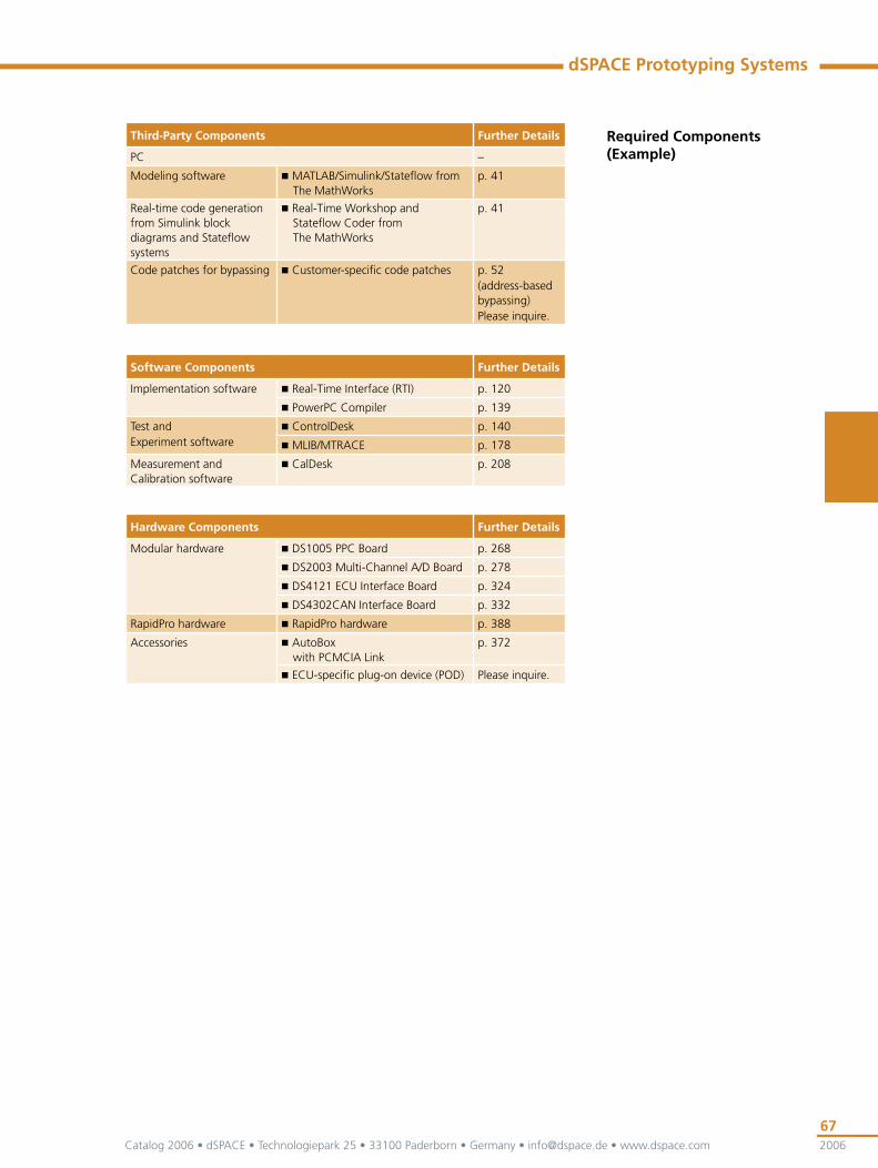
Required Components (Example)
Third-Party Components Further Details
PC with Ethernet interface –
Modeling software MATLAB/Simulink/Stateflow from The MathWorks
p. 41
Real-time code generation from Simulink block diagrams and Stateflow systems
Real-Time Workshop and Stateflow Coder from The MathWorks
p. 41
Software Components Further Details
Implementation software Real-Time Interface (RTI) p. 120
RTI CAN Blockset p. 128
PowerPC Compiler p. 139
Test and Experiment software
ControlDesk p. 140
MLIB/MTRACE p. 178
Hardware Components Further Details
Modular hardware DS1005 PPC Board p. 268
DS2003 Multi-Channel A/D Board p. 278
DS2103 Multi-Channel D/A Board p. 287
DS4002 Timing and Digital I/O Board p. 318
DS4302 CAN Interface Board p. 332
RapidPro hardware RapidPro Hardware p. 388
Accessories PX10 Expansion Box with Ethernet interface (via slot-CPU board)
p. 368
Catalog 2006 • dSPACE • Technologiepark 25 • 33100 Paderborn • Germany • [email protected] • www.dspace.com
62
Function Prototyping
2006
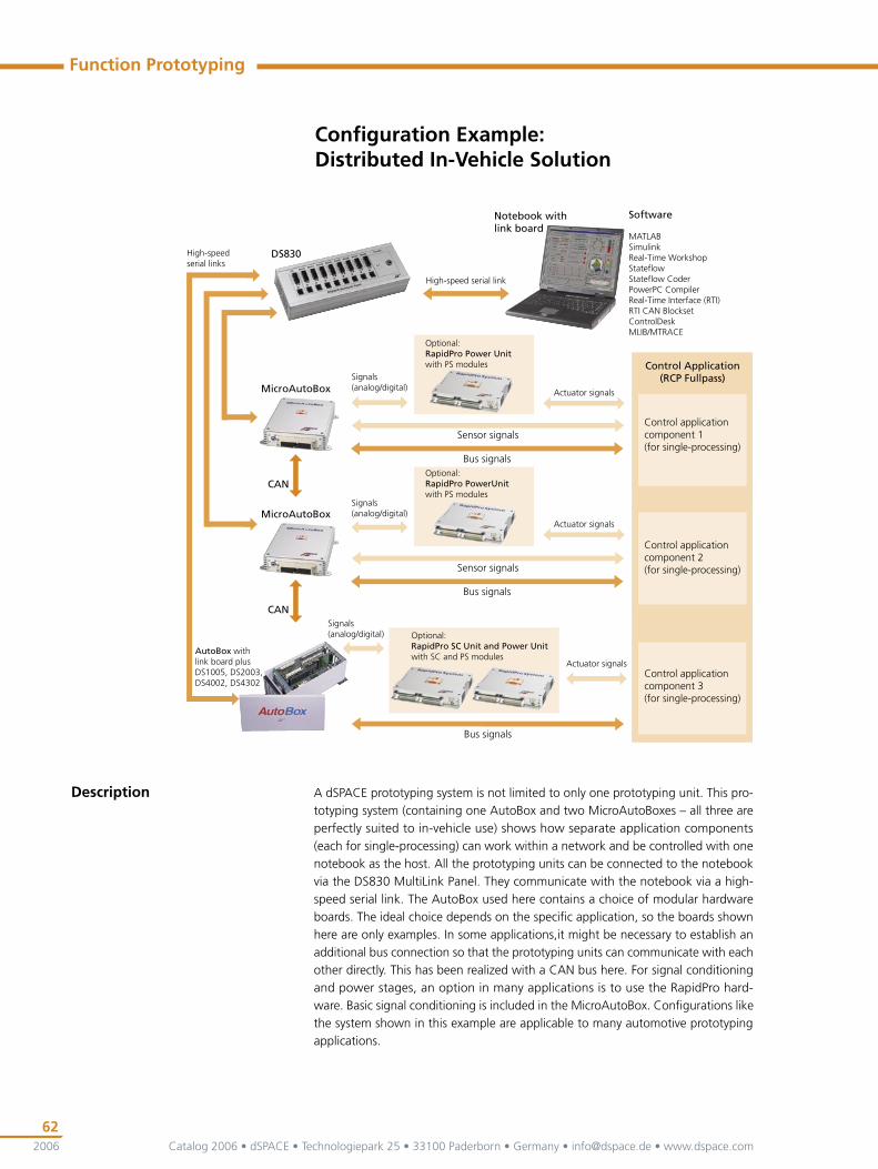
Configuration Example: Distributed In-Vehicle Solution
Description A dSPACE prototyping system is not limited to only one prototyping unit. This pro-
totyping system (containing one AutoBox and two MicroAutoBoxes – all three are
perfectly suited to in-vehicle use) shows how separate application components
(each for single-processing) can work within a network and be controlled with one
notebook as the host. All the prototyping units can be connected to the notebook
via the DS830 MultiLink Panel. They communicate with the notebook via a high-
speed serial link. The AutoBox used here contains a choice of modular hardware
boards. The ideal choice depends on the specific application, so the boards shown
here are only examples. In some applications,it might be necessary to establish an
additional bus connection so that the prototyping units can communicate with each
other directly. This has been realized with a CAN bus here. For signal conditioning
and power stages, an option in many applications is to use the RapidPro hard-
ware. Basic signal conditioning is included in the MicroAutoBox. Configurations like
the system shown in this example are applicable to many automotive prototyping
applications.
��������������
�����������
�����������������
�����������������
�����������������
��������������
�����������
�����������
����������������������
���������������������������������������������������������
������������������������������������������
������������������������
��������
���������������������������������������������������������������������������������������������������������������������������������������
���������������������������������
�������������������������������������������
������������������������
�����
��������������������������������������������������������������
������������������������������������������������������
������������������������������������������������������
������������
���
�����������������������
������������������������������������������������������
������������������������
������������������������
������������
���

Catalog 2006 • dSPACE • Technologiepark 25 • 33100 Paderborn • Germany • [email protected] • www.dspace.com 2006
63
dSPACE Prototyping Systems
Required Components (Example)
Third-Party Components Further Details
PC –
Modeling software MATLAB/Simulink/Stateflow from The MathWorks
p. 41
Real-time code generation from Simulink block diagrams and Stateflow systems
Real-Time Workshop and Stateflow Coder from The MathWorks
p. 41
Software Components Further Details
Implementation software Real-Time Interface (RTI) p. 120
RTI CAN Blockset p. 128
PowerPC Compiler p. 139
Test and Experiment software
ControlDesk p. 140
MLIB/MTRACE p. 178
Hardware Components Further Details
MicroAutoBox hardware MicroAutoBox p. 378
Modular hardware DS1005 PPC Board p. 268
DS2003 Multi-Channel A/D Board p. 278
DS4002 Timing and Digital I/O Board p. 318
DS4302 CAN Interface Board p. 332
RapidPro hardware RapidPro Hardware p. 388
Accessories AutoBox with PCMCIA Link
p. 372
DS830 MultiLink Panel p. 376

Catalog 2006 • dSPACE • Technologiepark 25 • 33100 Paderborn • Germany • [email protected] • www.dspace.com
64
Function Prototyping
2006
Configuration Example: Bypass Solution
Description Bypassing (p. 50) means that new functions are moved to the prototyping system,
while existing code continues to run on the ECU. An example of service-based by-
passing via the ECU‘s on-chip debug port is shown here. It is possible to read from
and to write to any ECU memory address synchronously to ECU code execution at
run time by this method. You can use the DCI-GSI1 (p. 430), which supports a range
of debug ports, as an interface between MicroAutoBox and the ECU. The debug
interface actually used for service-based bypassing depends on the ECU’s proces-
sor type. Here it is a JTAG/Nexus debug interface, which is suited to processors of
the Freescale MPC55xx family. The RTI Bypass Blockset allows you to configure the
bypass interface and the bypass functions.
����������������������
������������������������ ���������
��
��������������������������������������������������������������������������������������������������������������������������������������������������
�������������������������������������
������������
����
�����
����������������������������������
���
�������������������������������
�������������������������������������������

Catalog 2006 • dSPACE • Technologiepark 25 • 33100 Paderborn • Germany • [email protected] • www.dspace.com 2006
65
dSPACE Prototyping Systems
Required Components (Example)
Third-Party Components Further Details
PC –
Modeling software MATLAB/Simulink/Stateflow from The MathWorks
p. 41
Real-time code generation from Simulink block diagrams and Stateflow systems
Real-Time Workshop and Stateflow Coder from The MathWorks
p. 41
Software Components Further Details
Implementation software Real-Time Interface (RTI) p. 120
RTI Bypass Blockset (add-on installation for DCI-GSI1)
p. 136
PowerPC Compiler p. 139
Test and Experiment software
ControlDesk p. 140
MLIB/MTRACE p. 178
Measurement and Calibration software
CalDesk p. 208
Bypassing services dSPACE Calibration & Bypassing Service
p. 231(service-based bypassing)
Hardware Components Further Details
MicroAutoBox hardware MicroAutoBox with PCMCIA Link
p. 378
Calibration hardware DCI-GSI1 p. 430

Catalog 2006 • dSPACE • Technologiepark 25 • 33100 Paderborn • Germany • [email protected] • www.dspace.com
66
Function Prototyping
2006
Configuration Example: Bypass Solution with Additional I/O
Description If bypassed functions require additional I/O functionalities, these can also be provided
by a dSPACE prototyping system, as shown in this example. The prototyping system
itself is an AutoBox containing a choice of modular hardware boards. A processor
board and the ECU interface board are essential for bypassing, and you can equip the
AutoBox with the necessary I/O boards if additional I/O functionalities are needed. The
signal conditioning and power stages can be provided by our new RapidPro hardware.
With the prototyping system shown, you can perform address-based bypassing via
DPMEM. Bypassing methods and interfaces are described on p. 50 – p. 54.
����������������������
������������������������
�����������
�����������������������������������������������������������������������������������������������������������������������
����������������������
����
�������������������������������
���
�������������������������������
������������������������������
����������������������������������������������������������������������������������������
��������������������������������������������������������������
�������������������������
����������������������������������
Catalog 2006 • dSPACE • Technologiepark 25 • 33100 Paderborn • Germany • [email protected] • www.dspace.com 2006
67
dSPACE Prototyping Systems
Required Components (Example)
Third-Party Components Further Details
PC –
Modeling software MATLAB/Simulink/Stateflow from The MathWorks
p. 41
Real-time code generation from Simulink block diagrams and Stateflow systems
Real-Time Workshop and Stateflow Coder from The MathWorks
p. 41
Code patches for bypassing Customer-specific code patches p. 52(address-based bypassing)Please inquire.
Software Components Further Details
Implementation software Real-Time Interface (RTI) p. 120
PowerPC Compiler p. 139
Test and Experiment software
ControlDesk p. 140
MLIB/MTRACE p. 178
Measurement and Calibration software
CalDesk p. 208
Hardware Components Further Details
Modular hardware DS1005 PPC Board p. 268
DS2003 Multi-Channel A/D Board p. 278
DS4121 ECU Interface Board p. 324
DS4302CAN Interface Board p. 332
RapidPro hardware RapidPro hardware p. 388
Accessories AutoBox with PCMCIA Link
p. 372
ECU-specific plug-on device (POD) Please inquire.

Catalog 2006 • dSPACE • Technologiepark 25 • 33100 Paderborn • Germany • [email protected] • www.dspace.com
68
Function Prototyping
2006
��������
��������������������������������������������������������������������������������������������������������������������������������������
����������������������
������������
������������������
�������������������������������������������������������������������
���
���������
��� ���
������������������������
Configuration Example: Bypass Solution via XCP on CAN
Description A prime objective in function development using the external bypass approach is
often to employ existing ECU-network interfaces, such as CAN. Against the back-
ground of cost savings and long-term investment protection, this requires standard-
ized protocols like XCP – tailored not only to today’s but also to future in-vehicle
communication standards.
Apart from basic features such as measurement, calibration, and ECU flash pro-
gramming, the dSPACE XCP service (p. 230) also supports function bypassing.
In connection with a dSPACE prototyping system, the XCP service guarantees minimal
communication latencies via the CAN bus and real-time behavior even with complex
bypass models. Flexible configuration options make it possible to tailor the imple-
mentation of the service with regard to functionality and resource consumption in
the ECU. The XCP service implementation can be used simultaneously for bypass,
measurement, and calibration tasks.
In this example of service-based bypassing, the MicroAutoBox (p. 378) is used as a
real-time prototyping platform calculating the bypass model. Bypass communica-
tion with the ECU runs via the CAN bus using the XCP protocol. The dSPACE XCP
service is implemented on the ECU itself. CalDesk (p. 208) serves as an experiment
environment for the MicroAutoBox and – optionally – for measuring and calibrating
ECU variables via the USB-to-CAN converter DCI-CAN1 (p. 424). Measurement data
from the MicroAutoBox and the ECU can be correlated and parameters on both
platforms tuned in parallel in CalDesk.

Catalog 2006 • dSPACE • Technologiepark 25 • 33100 Paderborn • Germany • [email protected] • www.dspace.com 2006
69
dSPACE Prototyping Systems
Software Components Further Details
Implementation software Real-Time Interface (RTI) p. 120
RTI Bypass Blockset p. 136
PowerPC Compiler p. 139
Test and Experiment software
MLIB/MTRACE p. 178
Measurement and Calibration software
CalDesk p. 208
Bypassing services dSPACE XCP Service p. 230 (service-based bypassing)
Hardware Components Further Details
MicroAutoBox hardware MicroAutoBox p. 378
Calibration hardware DCI-CAN1 p. 424
Third-Party Components Further Details
Notebook –
Modeling software MATLAB/Simulink/Stateflow from The MathWorks
p. 41
Real-time code generation from Simulink block diagrams and Stateflow systems
Real-Time Workshop and Stateflow Coder from The MathWorks
p. 41
Related Documents