ESKOM COPYRIGHT PROTECTED B Morrison / Mar 2010 / Rev 1 SPECIFICATION Document Classification: Controlled Disclosure Title: Distribution Type – Part 15: SPECIFICATION FOR A VRW20 JUNCTION BOX Unique Identifier: 34-396 Document Type: DSP Revision: 1 Published date: MARCH 2010 Total pages: 23 Review date: MARCH 2015 COMPILED BY APPROVED BY FUNCTIONAL RESP AUTHORISED BY _ _ _ _ _ _ _ _ H SITHOLE _ _ _ _ _ _ _ _ A M A CRAIB _ _ _ _ _ _ _ _ P R GROENEWALD _ _ SIGNED _ _ MN BAILEY DT - CT Protection SC Chair for TESCOD CMDT for MD (Dx) DATE: 3 March 2010 DATE: 5 March 2010 DATE: 8 March 2010 DATE: 31/03/2010…… Content Page Foreword........................................................................................................................................................2 Introduction ....................................................................................................................................................3 1 Scope ....................................................................................................................................................3 2 Normative references............................................................................................................................4 3 Definitions and abbreviations ................................................................................................................5 3.1 Definitions .........................................................................................................................................5 3.2 Abbreviations ....................................................................................................................................5 4 Requirements ........................................................................................................................................5 4.1 Junction box detail ............................................................................................................................5 4.2 Gland Plate .......................................................................................................................................6 4.3 Insert Trays .......................................................................................................................................7 4.4 Corrosion Protection .........................................................................................................................8 4.5 Prototype ..........................................................................................................................................9 5 Tests .....................................................................................................................................................9 5.1 Wiring Tests ......................................................................................................................................9 6 Labelling, Packaging, Marking and Transport ....................................................................................10 6.1 Labelling .........................................................................................................................................10 6.2 Packaging .......................................................................................................................................10 6.3 Marking ...........................................................................................................................................10 6.4 Transport ........................................................................................................................................11 7 Spares .................................................................................................................................................11 Annex A – List of items required on contract...............................................................................................12 Annex B – Treatment of Columbus Stainless 3CR12 .................................................................................15 Annex C – Additional information – Photographs........................................................................................16 Annex D – Impact Assessment ...................................................................................................................20

Welcome message from author
This document is posted to help you gain knowledge. Please leave a comment to let me know what you think about it! Share it to your friends and learn new things together.
Transcript

ESKOM COPYRIGHT PROTECTED
B Morrison / Mar 2010 / Rev 1
SPECIFICATION
Document Classification: Controlled Disclosure Title: Distribution Type – Part 15:
SPECIFICATION FOR A VRW20 JUNCTION BOX
Unique Identifier: 34-396 Document Type: DSP Revision: 1
Published date: MARCH 2010
Total pages: 23 Review date: MARCH 2015
COMPILED BY APPROVED BY FUNCTIONAL RESP AUTHORISED BY
_ _ _ _ _ _ _ _
H SITHOLE
_ _ _ _ _ _ _ _
A M A CRAIB
_ _ _ _ _ _ _ _
P R GROENEWALD
_ _ SIGNED _ _
MN BAILEY DT - CT Protection SC Chair for TESCOD CMDT for MD (Dx)
DATE: 3 March 2010 DATE: 5 March 2010 DATE: 8 March 2010 DATE: 31/03/2010……
Content
Page Foreword ........................................................................................................................................................ 2 Introduction .................................................................................................................................................... 3 1 Scope .................................................................................................................................................... 3 2 Normative references ............................................................................................................................ 4 3 Definitions and abbreviations ................................................................................................................ 5
3.1 Definitions ......................................................................................................................................... 5 3.2 Abbreviations .................................................................................................................................... 5
4 Requirements ........................................................................................................................................ 5 4.1 Junction box detail ............................................................................................................................ 5 4.2 Gland Plate ....................................................................................................................................... 6 4.3 Insert Trays ....................................................................................................................................... 7 4.4 Corrosion Protection ......................................................................................................................... 8 4.5 Prototype .......................................................................................................................................... 9
5 Tests ..................................................................................................................................................... 9 5.1 Wiring Tests ...................................................................................................................................... 9
6 Labelling, Packaging, Marking and Transport .................................................................................... 10 6.1 Labelling ......................................................................................................................................... 10 6.2 Packaging ....................................................................................................................................... 10 6.3 Marking ........................................................................................................................................... 10 6.4 Transport ........................................................................................................................................ 11
7 Spares ................................................................................................................................................. 11 Annex A – List of items required on contract ............................................................................................... 12 Annex B – Treatment of Columbus Stainless 3CR12 ................................................................................. 15 Annex C – Additional information – Photographs ........................................................................................ 16 Annex D – Impact Assessment ................................................................................................................... 20
DOCUMENT CLASSIFICATION: CONTROLLED DISCLOSURE SPECIFICATION FOR A VRW20 JUNCTION BOX Unique Identifier: 34-396
Type: DSP Revision: 1 Page: 2 of 23
ESKOM COPYRIGHT PROTECTED
When downloaded from the IARC WEB, this document is uncontrolled and the responsibility rests with the user to ensure it is in line with the authorised version on the WEB.
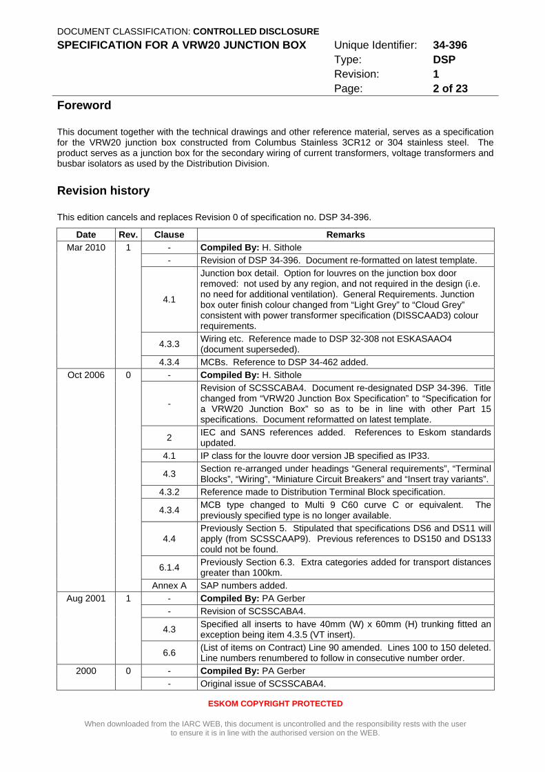
Foreword
This document together with the technical drawings and other reference material, serves as a specification for the VRW20 junction box constructed from Columbus Stainless 3CR12 or 304 stainless steel. The product serves as a junction box for the secondary wiring of current transformers, voltage transformers and busbar isolators as used by the Distribution Division.
Revision history
This edition cancels and replaces Revision 0 of specification no. DSP 34-396.
Date Rev. Clause Remarks Mar 2010 1 - Compiled By: H. Sithole
- Revision of DSP 34-396. Document re-formatted on latest template.
4.1
Junction box detail. Option for louvres on the junction box door removed: not used by any region, and not required in the design (i.e. no need for additional ventilation). General Requirements. Junction box outer finish colour changed from “Light Grey” to “Cloud Grey” consistent with power transformer specification (DISSCAAD3) colour requirements.
4.3.3 Wiring etc. Reference made to DSP 32-308 not ESKASAAO4 (document superseded).
4.3.4 MCBs. Reference to DSP 34-462 added. Oct 2006 0 - Compiled By: H. Sithole
-
Revision of SCSSCABA4. Document re-designated DSP 34-396. Title changed from “VRW20 Junction Box Specification” to “Specification for a VRW20 Junction Box” so as to be in line with other Part 15 specifications. Document reformatted on latest template.
2 IEC and SANS references added. References to Eskom standards updated.
4.1 IP class for the louvre door version JB specified as IP33.
4.3 Section re-arranged under headings “General requirements”, “Terminal Blocks”, “Wiring”, “Miniature Circuit Breakers” and “Insert tray variants”.
4.3.2 Reference made to Distribution Terminal Block specification.
4.3.4 MCB type changed to Multi 9 C60 curve C or equivalent. The previously specified type is no longer available.
4.4 Previously Section 5. Stipulated that specifications DS6 and DS11 will apply (from SCSSCAAP9). Previous references to DS150 and DS133 could not be found.
6.1.4 Previously Section 6.3. Extra categories added for transport distances greater than 100km.
Annex A SAP numbers added. Aug 2001 1 - Compiled By: PA Gerber
- Revision of SCSSCABA4.
4.3 Specified all inserts to have 40mm (W) x 60mm (H) trunking fitted an exception being item 4.3.5 (VT insert).
6.6 (List of items on Contract) Line 90 amended. Lines 100 to 150 deleted. Line numbers renumbered to follow in consecutive number order.
2000 0 - Compiled By: PA Gerber - Original issue of SCSSCABA4.

DOCUMENT CLASSIFICATION: CONTROLLED DISCLOSURE SPECIFICATION FOR A VRW20 JUNCTION BOX Unique Identifier: 34-396
Type: DSP Revision: 1 Page: 3 of 23
ESKOM COPYRIGHT PROTECTED
When downloaded from the IARC WEB, this document is uncontrolled and the responsibility rests with the user to ensure it is in line with the authorised version on the WEB.
Authorisation
This document has been seen and accepted by: Name Designation
M N Bailey Corporate Manager: Divisional Technology
P R Groenewald IARC Technology Development Manager – Control Technologies
A M A Craib Protection Study Committee Chairman
S J van Zyl IARC Protection Specialist
This specification shall apply throughout the Distribution Division of Eskom Holdings Limited.
Development team
This document was originally compiled Paul Gerber. The present and previous revisions were compiled by Haggai Sithole with input from Paul Gerber and Stuart van Zyl.
Introduction
The VRW20 junction box is a standardized Distribution product. It shall be utilised by all Distribution Regions with the appropriate terminal insert plate for the termination of secondary cabling and wiring from post-type current and voltage transformers. It is also used in double busbar stations for the rationalisation of cables to busbar isolators (i.e. isolator junction box) and other non standard junction box requirements. This junction box design forms part of the standard substation equipment list.
Keywords
VRW20, Junction Box, Stainless Steel, 3CR12
Bibliography
Not applicable.
1 Scope
This document provides a detailed specification of the product, including exact dimensions, materials to be used, the painting process and the commercial end-user requirements. A prospective buyer shall be able to utilise this document together with the appropriate commercial documentation to purchase the product from prospective suppliers.
The manufacturer/supplier shall be able to manufacturer the product without need for additional technical support. The manufacturer may, with written authorization, make small dimensional and design changes should this allow easier manufacture of the junction box. These changes shall not however, compromise the quality of the box. Tenders shall be based on the design as supplied.
DOCUMENT CLASSIFICATION: CONTROLLED DISCLOSURE SPECIFICATION FOR A VRW20 JUNCTION BOX Unique Identifier: 34-396
Type: DSP Revision: 1 Page: 4 of 23
ESKOM COPYRIGHT PROTECTED
When downloaded from the IARC WEB, this document is uncontrolled and the responsibility rests with the user to ensure it is in line with the authorised version on the WEB.
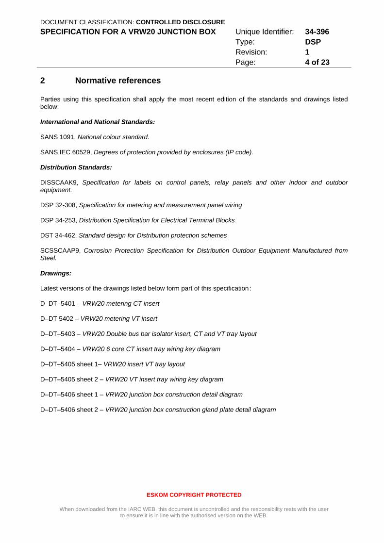
2 Normative references
Parties using this specification shall apply the most recent edition of the standards and drawings listed below:
International and National Standards:
SANS 1091, National colour standard.
SANS IEC 60529, Degrees of protection provided by enclosures (IP code).
Distribution Standards:
DISSCAAK9, Specification for labels on control panels, relay panels and other indoor and outdoor equipment.
DSP 32-308, Specification for metering and measurement panel wiring
DSP 34-253, Distribution Specification for Electrical Terminal Blocks
DST 34-462, Standard design for Distribution protection schemes
SCSSCAAP9, Corrosion Protection Specification for Distribution Outdoor Equipment Manufactured from Steel.
Drawings:
Latest versions of the drawings listed below form part of this specification :
D–DT–5401 – VRW20 metering CT insert
D–DT 5402 – VRW20 metering VT insert
D–DT–5403 – VRW20 Double bus bar isolator insert, CT and VT tray layout
D–DT–5404 – VRW20 6 core CT insert tray wiring key diagram
D–DT–5405 sheet 1– VRW20 insert VT tray layout
D–DT–5405 sheet 2 – VRW20 VT insert tray wiring key diagram
D–DT–5406 sheet 1 – VRW20 junction box construction detail diagram
D–DT–5406 sheet 2 – VRW20 junction box construction gland plate detail diagram
DOCUMENT CLASSIFICATION: CONTROLLED DISCLOSURE SPECIFICATION FOR A VRW20 JUNCTION BOX Unique Identifier: 34-396
Type: DSP Revision: 1 Page: 5 of 23
ESKOM COPYRIGHT PROTECTED
When downloaded from the IARC WEB, this document is uncontrolled and the responsibility rests with the user to ensure it is in line with the authorised version on the WEB.
3 Definitions and abbreviations
3.1 Definitions
None
3.2 Abbreviations
CT: Current Transformer
DT: Distribution Technology
JB: Junction Box
MCB: Miniature Circuit Breaker
VRW20: Historical abbreviation specifying junction boxes as detailed in this specification
VT: Voltage Transformer
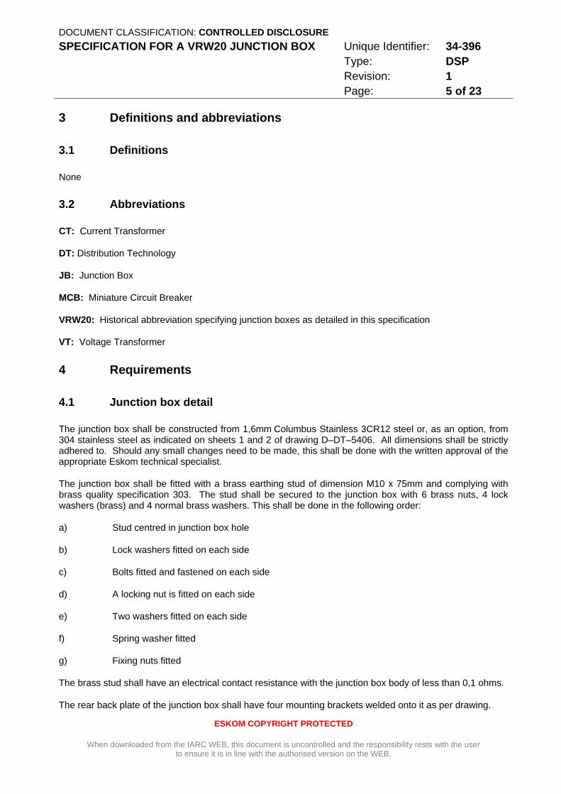
4 Requirements
4.1 Junction box detail
The junction box shall be constructed from 1,6mm Columbus Stainless 3CR12 steel or, as an option, from 304 stainless steel as indicated on sheets 1 and 2 of drawing D–DT–5406. All dimensions shall be strictly adhered to. Should any small changes need to be made, this shall be done with the written approval of the appropriate Eskom technical specialist.
The junction box shall be fitted with a brass earthing stud of dimension M10 x 75mm and complying with brass quality specification 303. The stud shall be secured to the junction box with 6 brass nuts, 4 lock washers (brass) and 4 normal brass washers. This shall be done in the following order:
a) Stud centred in junction box hole
b) Lock washers fitted on each side
c) Bolts fitted and fastened on each side
d) A locking nut is fitted on each side
e) Two washers fitted on each side
f) Spring washer fitted
g) Fixing nuts fitted
The brass stud shall have an electrical contact resistance with the junction box body of less than 0,1 ohms.
The rear back plate of the junction box shall have four mounting brackets welded onto it as per drawing.

DOCUMENT CLASSIFICATION: CONTROLLED DISCLOSURE SPECIFICATION FOR A VRW20 JUNCTION BOX Unique Identifier: 34-396
Type: DSP Revision: 1 Page: 6 of 23
ESKOM COPYRIGHT PROTECTED
When downloaded from the IARC WEB, this document is uncontrolled and the responsibility rests with the user to ensure it is in line with the authorised version on the WEB.
The interior shall have four studs of dimensions M6 x 25mm welded to the back plate. The studs shall be centrally arranged inside the junction box to the dimension of the insert tray mounting holes. The studs shall be made from stainless steel.
All parts and fixtures shall be made from stainless steel 304, Columbus Stainless 3CR12 or brass. All welds shall be waterproof. The welds shall be completed with a MIG welder and 3CR12 or stainless steel wire.
Treatment of 3CR12 shall be done in accordance with the recommendations of Columbus Steel, selected details of which are included in Annex B.
The box shall be manufactured in such a manner that contamination from other metals, including steel, is not possible. Contamination would occur if, for example, an angle grinder that has just been used on mild steel was used in the manufacture of the box. Contamination can also occur if the box is left in an environment where metal particles can make contact with the box. Contamination is not permitted due to its corrosive effect on the Columbus Stainless 3CR12 and also causes rust to occur on the mild steel.
The box shall be protected from water and dust ingress to class IP53.
The box shall be painted and treated in accordance with SCSSCAAP9. The box shall be texture powder coated to colour “Cloud Grey”, (NCS – 2305-R99B).
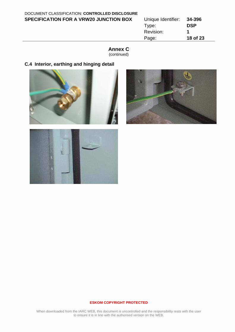
The junction box door shall be fixed to the body using two sturdy non-corroding hinges. The door lock shall be sturdy and made from a non-corroding material. The junction box door shall be earthed to the brass earth stud using green insulated 1000 VAC 2,5mm2 mullet strand copper wire. The contact resistance between the brass earth stud and any part of the gland plate and door shall be less than 0,1 ohms. The earth strap shall be long enough to allow the door to open fully.
The door shall be fitted with a quality gasket such that the sealing material shall always return to its original profile after compression. The material so used shall not deteriorate over the 15 year expected life span of the product.
Four stainless steel J bolts (304 stainless steel or higher specification), with eight nuts and eight washers also manufactured from stainless steel, shall be provided inside the junction box in a plastic bag suitably fixed so as not to cause transport related damage to the interior.
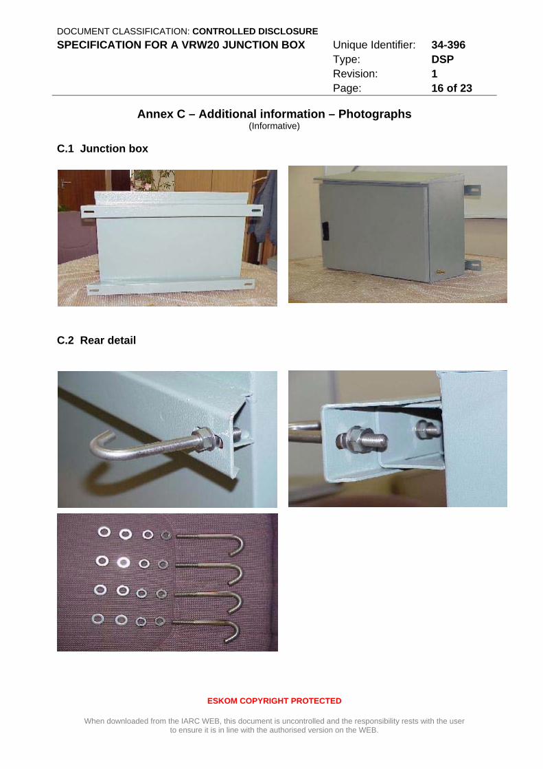
Refer to the photographs in Annex C for further details.
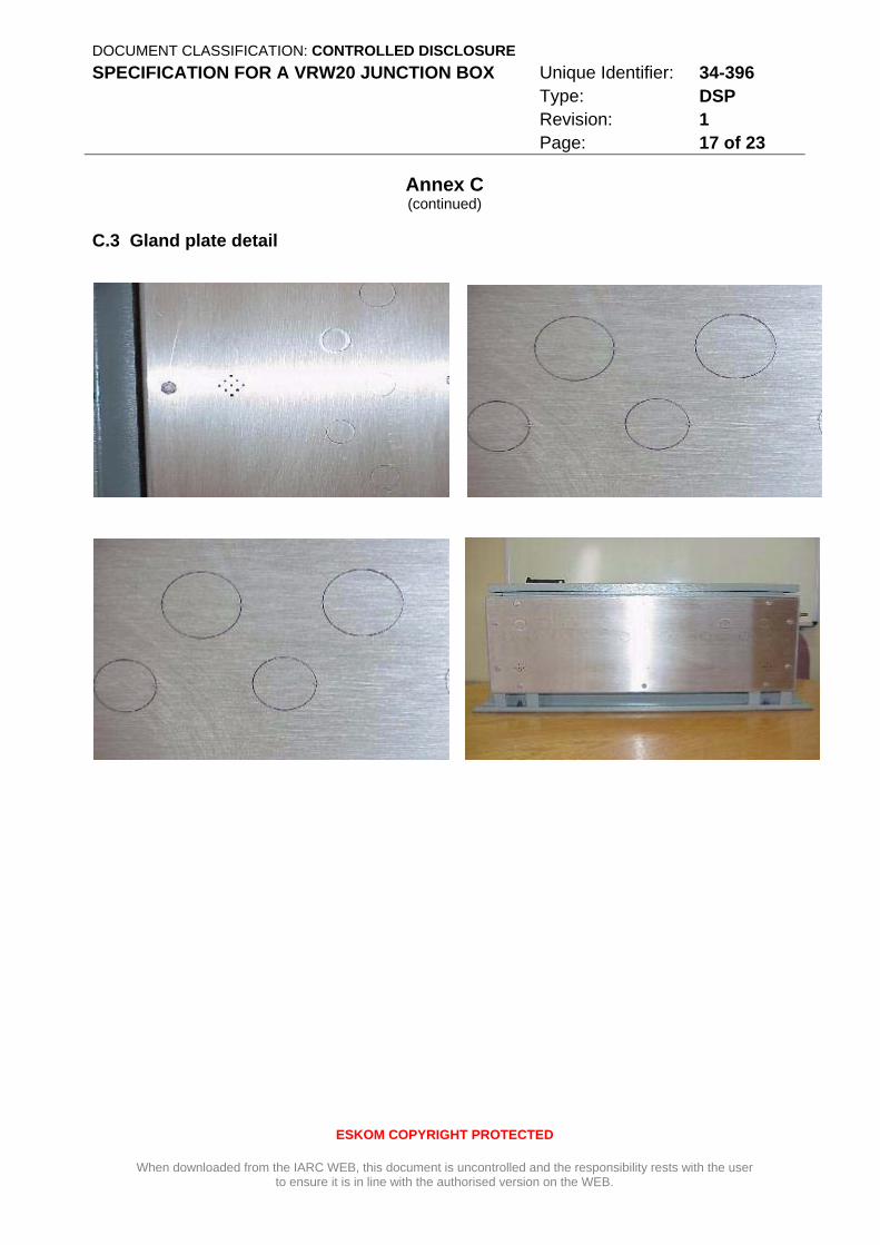
4.2 Gland Plate
The gland plate shall be made of 2mm thick 304 stainless steel. The plate shall have pre-punched cut-outs for the cable glands.
The gland plate shall have drainage/ventilation holes as indicated on the drawing. The drainage holes are included to allow for the venting of condensation and to drain off water that enters the junction box due to capillary action via the cable sheaths.
The gland plate shall be bolted to the junction box with stainless steel bolts. Spring washers shall be used between the junction box body and the fastening nut. The primary function of the spring washers is to allow for improved electrical connectivity between the gland plate and the junction box body.
In addition to the fastening bolts, the gland plate shall be earthed to the brass earthing stud by means of a braided tinned-copper earthing strap with an effective copper cross sectional area of 12mm2.
The contact resistance between the brass stud and any part of the gland plate shall be less than 0,1 ohms.
DOCUMENT CLASSIFICATION: CONTROLLED DISCLOSURE SPECIFICATION FOR A VRW20 JUNCTION BOX Unique Identifier: 34-396
Type: DSP Revision: 1 Page: 7 of 23
ESKOM COPYRIGHT PROTECTED
When downloaded from the IARC WEB, this document is uncontrolled and the responsibility rests with the user to ensure it is in line with the authorised version on the WEB.
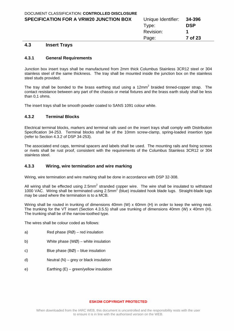
4.3 Insert Trays
4.3.1 General Requirements
Junction box insert trays shall be manufactured from 2mm thick Columbus Stainless 3CR12 steel or 304 stainless steel of the same thickness. The tray shall be mounted inside the junction box on the stainless steel studs provided.
The tray shall be bonded to the brass earthing stud using a 12mm2 braided tinned-copper strap. The contact resistance between any part of the chassis or metal fixtures and the brass earth study shall be less than 0,1 ohms.
The insert trays shall be smooth powder coated to SANS 1091 colour white.
4.3.2 Terminal Blocks
Electrical terminal blocks, markers and terminal rails used on the insert trays shall comply with Distribution Specification 34-253. Terminal blocks shall be of the 10mm screw-clamp, spring-loaded insertion type (refer to Section 4.3.2 of DSP 34-253).
The associated end caps, terminal spacers and labels shall be used. The mounting rails and fixing screws or rivets shall be rust proof, consistent with the requirements of the Columbus Stainless 3CR12 or 304 stainless steel.
4.3.3 Wiring, wire termination and wire marking
Wiring, wire termination and wire marking shall be done in accordance with DSP 32-308.
All wiring shall be effected using 2.5mm2 stranded copper wire. The wire shall be insulated to withstand 1000 VAC. Wiring shall be terminated using 2.5mm2 (blue) insulated hook blade lugs. Straight-blade lugs may be used where the termination is to a MCB.
Wiring shall be routed in trunking of dimensions 40mm (W) x 60mm (H) in order to keep the wiring neat. The trunking for the VT insert (Section 4.3.5.5) shall use trunking of dimensions 40mm (W) x 40mm (H). The trunking shall be of the narrow-toothed type.
The wires shall be colour coded as follows:
a) Red phase (RØ) – red insulation
b) White phase (WØ) – white insulation
c) Blue phase (BØ) – blue insulation
d) Neutral (N) – grey or black insulation
e) Earthing (E) – green/yellow insulation
DOCUMENT CLASSIFICATION: CONTROLLED DISCLOSURE SPECIFICATION FOR A VRW20 JUNCTION BOX Unique Identifier: 34-396
Type: DSP Revision: 1 Page: 8 of 23
ESKOM COPYRIGHT PROTECTED
When downloaded from the IARC WEB, this document is uncontrolled and the responsibility rests with the user to ensure it is in line with the authorised version on the WEB.
4.3.4 Miniature Circuit Breakers
MCBs to be included in the VT tray inserts shall be in accordance with DSP 34-462 Section 4.6.5 and subject to Eskom approval. The MCBs shall be rated for 10A, curve C with a breaking capacity of at least 4,5kA.
Three single phase MCBs will be provided per circuit as specified. Each phase of the MCB will be able to operate independently of the others.
4.3.5 Insert tray variants
The insert tray shall be available in the following options:
4.3.5.1 Metering CT insert (D–DT–5401)
This is a non-standard/custom metering CT insert.
4.3.5.2 Metering VT insert (D–DT–5402)
This is a non-standard/custom metering VT insert. This item shall include twelve MCBs (i.e. four three phase circuits) in accordance with the requirements of Section 4.3.4.
4.3.5.3 Double bus bar isolator insert (D-DT–5403)
This tray is used as an interface between the protection panels and the busbar and line isolator secondary contact boxes. The tray makes provision for zone selection of bus zone CTs as well as busbar VT selection, routed via the busbar isolator secondary contacts.
4.3.5.4 Six core CT insert tray (D–DT–5404)
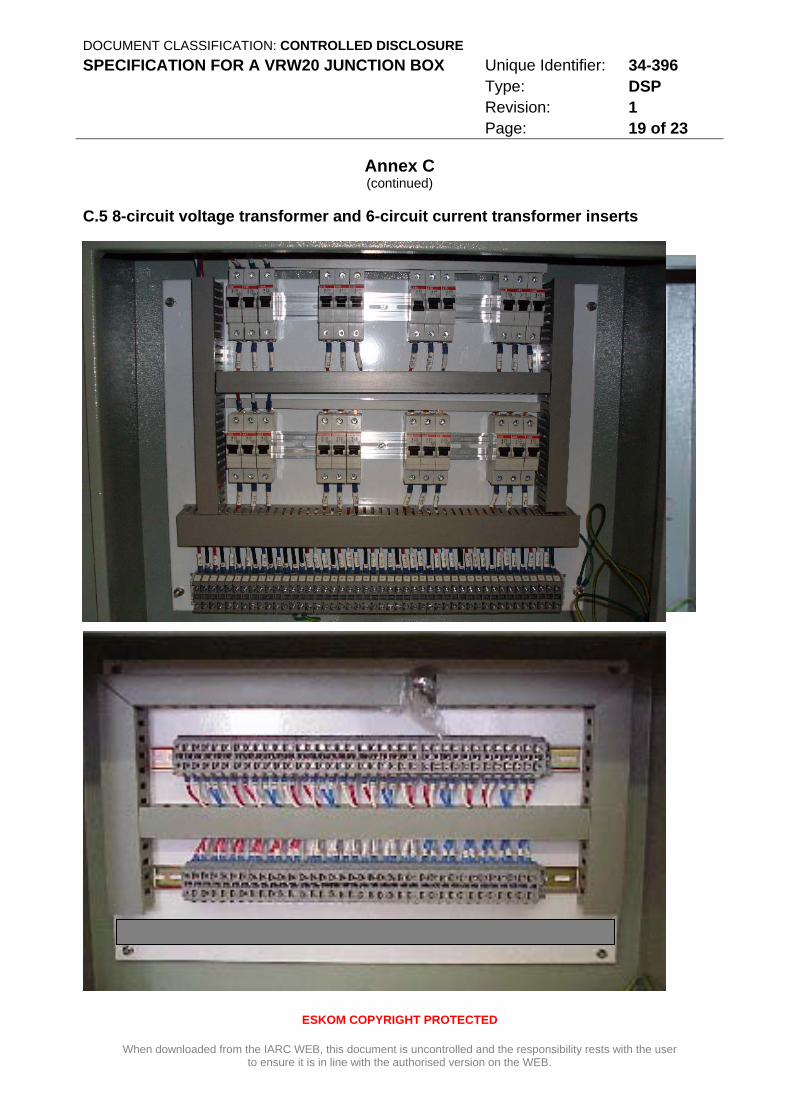
This is the standard CT insert tray, accommodating up to six CT cores from each of three post-type CTs.
4.3.5.5 VT insert (D–DT–5405)
This is the standard VT insert tray, accommodating eight circuits that are protected separately. Four circuits shall be routed from the first secondary winding of the VT and four shall be routed from the second secondary winding.
This item shall include twenty four MCBs (i.e. eight three phase circuits). MCBs shall be in accordance with the requirements of Section 4.3.4.
4.4 Corrosion Protection
The latest revision of the specification SCSSCAAP9 shall apply to the junction box body, door, gland plate and the inserts.
DOCUMENT CLASSIFICATION: CONTROLLED DISCLOSURE SPECIFICATION FOR A VRW20 JUNCTION BOX Unique Identifier: 34-396
Type: DSP Revision: 1 Page: 9 of 23
ESKOM COPYRIGHT PROTECTED
When downloaded from the IARC WEB, this document is uncontrolled and the responsibility rests with the user to ensure it is in line with the authorised version on the WEB.
4.5 Prototype
A sample junction box may be loaned to suppliers passing the pre-qualification process so as to facilitate the manufacturing set up (subject to availability of stock). A prototype of each item, which shall be returned in due course, shall be supplied to Eskom. Eskom shall inspect/test the prototype before acceptance and registration of the products on the List of Accepted Products.
5 Tests
5.1 Wiring Tests
The inserts shall all be tested for continuity. The continuity test shall give a reading of less than 0,1 ohms. Testing shall also include all earthing points. Where MCBs are used, tests shall be done with the MCBs selected to the “on” position and shall be repeated with MCBs off to confirm that they break the circuit.
The wiring insulation to earth as well as between circuits shall be checked with a 500 Vdc Megger. The pass criterion is a reading of 20 Megaohms or higher when testing between any part of the circuit and any part of the chassis as well as any separate circuit. The test shall be performed with any MCBs in the off and on positions. When the junction box is ordered with an insert already fitted, the test shall be performed with the insert in place.
The test equipment shall be tested/calibrated by an accredited testing laboratory at least once every six months. Proof of calibration shall be supplied to Eskom upon request.
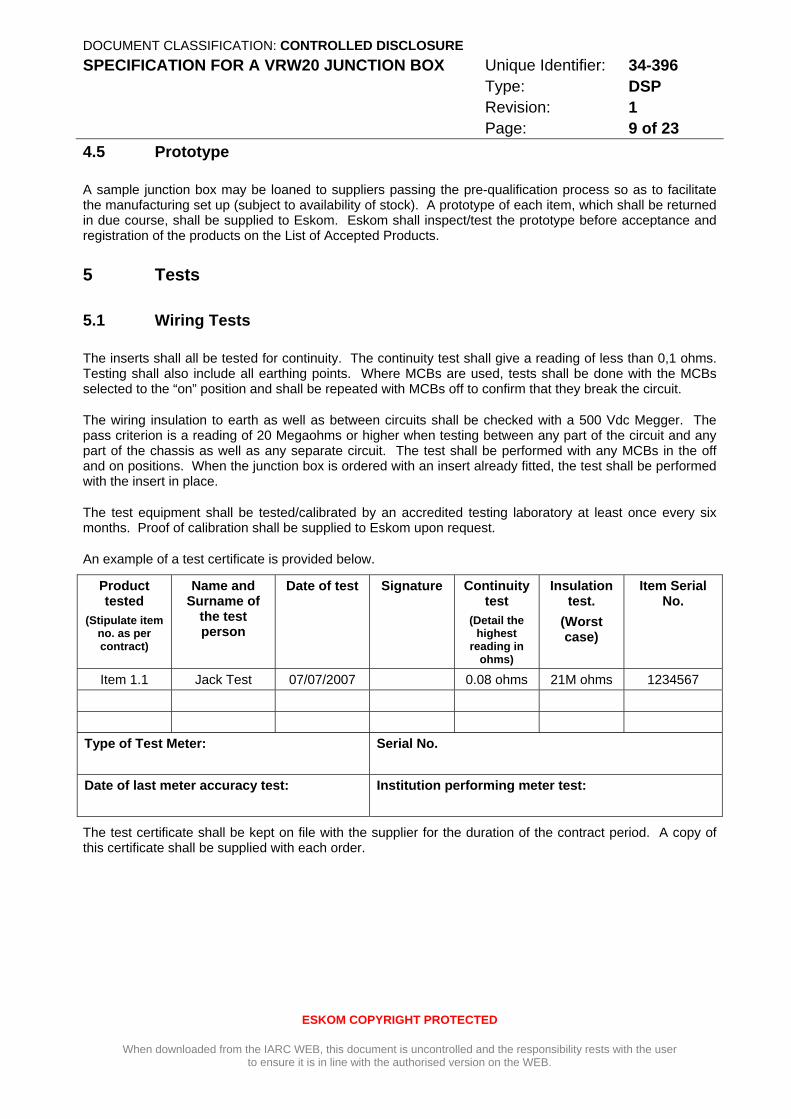
An example of a test certificate is provided below.
Product tested
(Stipulate item no. as per contract)
Name and Surname of
the test person
Date of test Signature
Continuity test
(Detail the highest
reading in ohms)
Insulation test.
(Worst case)
Item Serial No.
Item 1.1 Jack Test 07/07/2007 0.08 ohms 21M ohms 1234567 Type of Test Meter:
Serial No.
Date of last meter accuracy test:
Institution performing meter test:
The test certificate shall be kept on file with the supplier for the duration of the contract period. A copy of this certificate shall be supplied with each order.

DOCUMENT CLASSIFICATION: CONTROLLED DISCLOSURE SPECIFICATION FOR A VRW20 JUNCTION BOX Unique Identifier: 34-396
Type: DSP Revision: 1 Page: 10 of 23
ESKOM COPYRIGHT PROTECTED
When downloaded from the IARC WEB, this document is uncontrolled and the responsibility rests with the user to ensure it is in line with the authorised version on the WEB.
6 Labelling, Packaging, Marking and Transport
6.1 Labelling
Each junction box shall have a label fixed to the outside rear, with a short description of the insert type fitted e.g. 8 circuit VT insert or 6 circuit CT insert, Metering CT insert, Metering VT insert etc.. Where there is a blank insert fitted, it shall clearly be stated that a blank is inserted. The label may be a sticker type as it merely serves to indicate to the installer the type of box being installed.
A durable weatherproof label shall be provided on the inside of the junction box door, including the following details:
a) Product description: “VRW20 Junction Box to D-DT-5405 Rev X”.
b) Material: 3CR12 OR 304 Stainless Steel (as appropriate)
c) Supplier’s name;
d) Physical address;
e) Contact telephone number;
f) Date of manufacture; and
g) serial number. Each junction box shall have a unique serial number.
The terminal strips shall be designated X1, X2, and X3 as per the drawings. This shall be done using an engraved label.
6.2 Packaging
The junction boxes and inserts shall be packed in a high specification impact resistant corrugated cardboard box with a waterproof outer plastic covering. The container shall protect the box and its contents from reasonable transport related wear and tear from the supplier’s works to the end user. The packaging shall be clearly marked as indicated below. The junction box J bolts, complete with washers, shall be packaged inside the junction box in plastic bag secured internally.
6.3 Marking
The outside of the packaging will be clearly marked indicating:
a) Substation name
b) Detailed delivery address
c) Detailed description of contents as per order
d) Dispatch date
e) Eskom and Supplier order number
DOCUMENT CLASSIFICATION: CONTROLLED DISCLOSURE SPECIFICATION FOR A VRW20 JUNCTION BOX Unique Identifier: 34-396
Type: DSP Revision: 1 Page: 11 of 23
ESKOM COPYRIGHT PROTECTED
When downloaded from the IARC WEB, this document is uncontrolled and the responsibility rests with the user to ensure it is in line with the authorised version on the WEB.
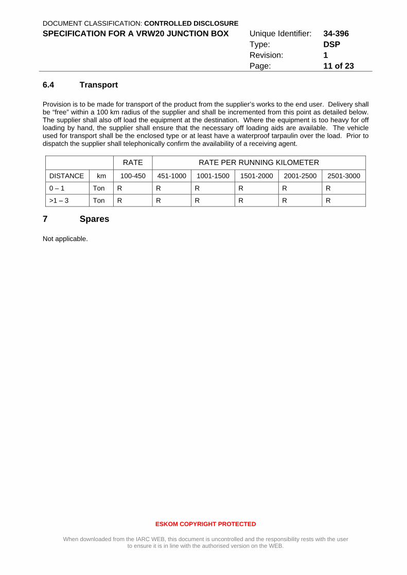
6.4 Transport
Provision is to be made for transport of the product from the supplier’s works to the end user. Delivery shall be “free” within a 100 km radius of the supplier and shall be incremented from this point as detailed below. The supplier shall also off load the equipment at the destination. Where the equipment is too heavy for off loading by hand, the supplier shall ensure that the necessary off loading aids are available. The vehicle used for transport shall be the enclosed type or at least have a waterproof tarpaulin over the load. Prior to dispatch the supplier shall telephonically confirm the availability of a receiving agent.
RATE RATE PER RUNNING KILOMETER
DISTANCE km 100-450 451-1000 1001-1500 1501-2000 2001-2500 2501-3000
0 – 1 Ton R R R R R R
>1 – 3 Ton R R R R R R
7 Spares
Not applicable.
DOCUMENT CLASSIFICATION: CONTROLLED DISCLOSURE SPECIFICATION FOR A VRW20 JUNCTION BOX Unique Identifier: 34-396
Type: DSP Revision: 1 Page: 12 of 23
ESKOM COPYRIGHT PROTECTED
When downloaded from the IARC WEB, this document is uncontrolled and the responsibility rests with the user to ensure it is in line with the authorised version on the WEB.
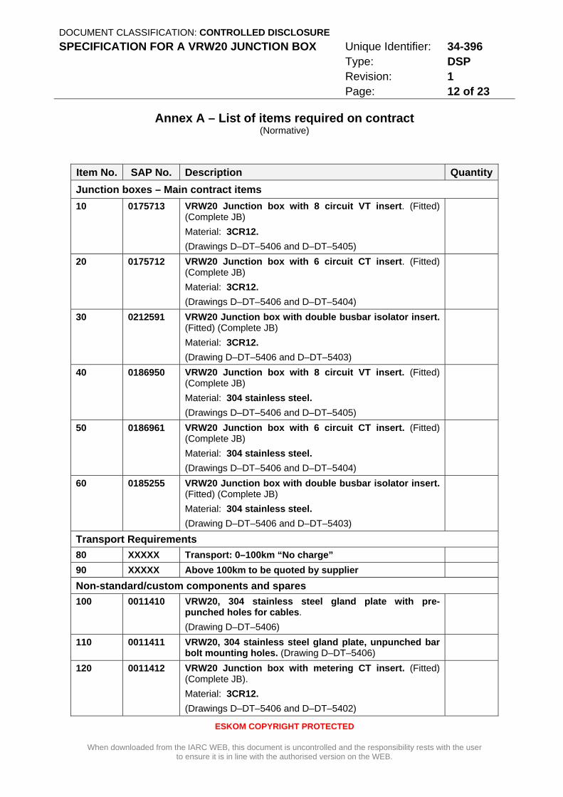
Annex A – List of items required on contract (Normative)
Item No. SAP No. Description QuantityJunction boxes – Main contract items 10 0175713 VRW20 Junction box with 8 circuit VT insert. (Fitted)
(Complete JB) Material: 3CR12. (Drawings D–DT–5406 and D–DT–5405)
20 0175712 VRW20 Junction box with 6 circuit CT insert. (Fitted) (Complete JB) Material: 3CR12. (Drawings D–DT–5406 and D–DT–5404)
30 0212591 VRW20 Junction box with double busbar isolator insert. (Fitted) (Complete JB) Material: 3CR12. (Drawing D–DT–5406 and D–DT–5403)
40 0186950 VRW20 Junction box with 8 circuit VT insert. (Fitted) (Complete JB) Material: 304 stainless steel. (Drawings D–DT–5406 and D–DT–5405)
50 0186961 VRW20 Junction box with 6 circuit CT insert. (Fitted) (Complete JB) Material: 304 stainless steel. (Drawings D–DT–5406 and D–DT–5404)
60 0185255 VRW20 Junction box with double busbar isolator insert. (Fitted) (Complete JB) Material: 304 stainless steel. (Drawing D–DT–5406 and D–DT–5403)
Transport Requirements 80 XXXXX Transport: 0–100km “No charge” 90 XXXXX Above 100km to be quoted by supplier
Non-standard/custom components and spares 100 0011410 VRW20, 304 stainless steel gland plate with pre-
punched holes for cables. (Drawing D–DT–5406)
110 0011411 VRW20, 304 stainless steel gland plate, unpunched bar bolt mounting holes. (Drawing D–DT–5406)
120 0011412 VRW20 Junction box with metering CT insert. (Fitted) (Complete JB). Material: 3CR12. (Drawings D–DT–5406 and D–DT–5402)
DOCUMENT CLASSIFICATION: CONTROLLED DISCLOSURE SPECIFICATION FOR A VRW20 JUNCTION BOX Unique Identifier: 34-396
Type: DSP Revision: 1 Page: 13 of 23
ESKOM COPYRIGHT PROTECTED
When downloaded from the IARC WEB, this document is uncontrolled and the responsibility rests with the user to ensure it is in line with the authorised version on the WEB.
Annex A (continued)
Item No. SAP No. Description Quantity130 0011408 VRW20 Junction box with metering VT insert. (Fitted)
(Complete JB). Material: 3CR12. (Drawing D–DT–5406 and D–DT–5402)
140 0011621 VRW20 Junction box complete with unpunched (blank) insert. (Fitted) (Complete JB) Material: 3CR12. (Drawing D–DT–5406)
150 0011384 VRW20 3CR12 6 circuit CT insert. (Insert only). (Drawing D–DT–5404)
160 0011622 VRW20 3CR12 8 circuit VT insert. (Insert only). (Drawing D–DT–5405)
170 0168772 VRW20 3CR12 Double busbar isolator insert. (Insert only). (Drawing D–DT –5403)
180 0011625 VRW20 3CR12 Metering circuit CT insert. (Insert only). (Drawing D–DT–5401)
190 0011623 VRW20 3CR12 Metering circuit VT insert. (Insert only). (Drawing D–DT–5402)
200 0011409 VRW20 3CR12 blank insert, painted white, no pre punched holes bar the 4 corner mounting holes. (Insert only). (Drawing D–DT–5406)
210 0186964 VRW20 Junction box with metering CT insert. (Fitted) (Complete JB). Material: 304 stainless steel. (Drawings D–DT–5406 and D–DT–5401)
220 0186965 VRW20 Junction box with metering VT insert. (Fitted) (Complete JB). Material: 304 stainless steel. (Drawings D–DT–5406 and D–DT–5402)
230 0186972 VRW20 Junction box complete with unpunched (blank) insert. (Fitted) (Complete JB) 304 stainless steel. (Drawing D–DT–5406)
240 0186968 VRW20 6 circuit CT insert. 304 stainless steel. (Insert only). (Drawing D–DT –5404)
DOCUMENT CLASSIFICATION: CONTROLLED DISCLOSURE SPECIFICATION FOR A VRW20 JUNCTION BOX Unique Identifier: 34-396
Type: DSP Revision: 1 Page: 14 of 23
ESKOM COPYRIGHT PROTECTED
When downloaded from the IARC WEB, this document is uncontrolled and the responsibility rests with the user to ensure it is in line with the authorised version on the WEB.
Annex A (continued)
Item No. SAP No. Description Quantity250 0186969 VRW20 8 circuit VT insert. 304 stainless steel.
(Insert only). (Drawing D–DT–5405)
260 0186970 VRW20 Double busbar isolator insert. 304 stainless steel. (Insert only). (Drawing as per D–DT–5403)
270 0186966 VRW20 metering circuit CT insert. 304 stainless steel. (Insert only). (Drawing D–DT–5401)
280 0186967 VRW20 metering circuit VT insert. 304 stainless steel. (Insert only). (Drawing D–DT–5402)
290 0186971 VRW20 Junction box, blank 304 stainless steel insert, painted white, no pre punched holes, bar the 4 corner mounting holes. (Insert only). (Drawing D–DT–5406)
DOCUMENT CLASSIFICATION: CONTROLLED DISCLOSURE SPECIFICATION FOR A VRW20 JUNCTION BOX Unique Identifier: 34-396
Type: DSP Revision: 1 Page: 15 of 23
ESKOM COPYRIGHT PROTECTED
When downloaded from the IARC WEB, this document is uncontrolled and the responsibility rests with the user to ensure it is in line with the authorised version on the WEB.
Annex B – Treatment of Columbus Stainless 3CR12 (Normative)
The processes followed shall conform to that of Columbus Steel from whose guide the following general considerations were extracted. The supplier shall attach a description of the 3CR12 treatment process to their tender. This will be shared with Columbus Stainless to ensure that the process is to the correct standard. This includes but is not limited to pickling, passivation and coating. Further information may be obtained from the Columbus webpage.
B.1 Surface preparation
The surface must be as clean and as grease-free as possible. Surface preparation is to be done after the fabrication process.
B.1.1 Cleaning method – pickling
Mill scale and weld oxidation may be removed by pickling. Fabricated particles can be pickled by either full immersion in a pickling bath, if the size allows, or by pickling pastes. Pickling formulations should be based on nitric acid. Hydrochloric acid solutions should not be used. Pickling pastes can cause staining if allowed to dry. Contact times can be determined by experimentation, but should allow sufficient time to remove the scale and heat tint.
Although pickling is usually followed by passivation in order to achieve optimum corrosion resistance, passivation prior to coating can lead to paint adhesion problems. Fabricated articles can be coated straight after pickling provided that the pickled surfaces are thoroughly rinsed in cold water and dried thereafter.
B.1.2 Coating
The paint used must comply with the specification provided. It is advised that the paints used for a particular paint system be sourced from the same supplier. Due to the inherent smooth surface of Columbus Stainless 3CR12, a primer is essential.
DOCUMENT CLASSIFICATION: CONTROLLED DISCLOSURE SPECIFICATION FOR A VRW20 JUNCTION BOX Unique Identifier: 34-396
Type: DSP Revision: 1 Page: 16 of 23
ESKOM COPYRIGHT PROTECTED
When downloaded from the IARC WEB, this document is uncontrolled and the responsibility rests with the user to ensure it is in line with the authorised version on the WEB.
Annex C – Additional information – Photographs (Informative)
C.1 Junction box
C.2 Rear detail
DOCUMENT CLASSIFICATION: CONTROLLED DISCLOSURE SPECIFICATION FOR A VRW20 JUNCTION BOX Unique Identifier: 34-396
Type: DSP Revision: 1 Page: 17 of 23
ESKOM COPYRIGHT PROTECTED
When downloaded from the IARC WEB, this document is uncontrolled and the responsibility rests with the user to ensure it is in line with the authorised version on the WEB.
Annex C (continued)
C.3 Gland plate detail
DOCUMENT CLASSIFICATION: CONTROLLED DISCLOSURE SPECIFICATION FOR A VRW20 JUNCTION BOX Unique Identifier: 34-396
Type: DSP Revision: 1 Page: 18 of 23
ESKOM COPYRIGHT PROTECTED
When downloaded from the IARC WEB, this document is uncontrolled and the responsibility rests with the user to ensure it is in line with the authorised version on the WEB.
Annex C (continued)
C.4 Interior, earthing and hinging detail
DOCUMENT CLASSIFICATION: CONTROLLED DISCLOSURE SPECIFICATION FOR A VRW20 JUNCTION BOX Unique Identifier: 34-396
Type: DSP Revision: 1 Page: 19 of 23
ESKOM COPYRIGHT PROTECTED
When downloaded from the IARC WEB, this document is uncontrolled and the responsibility rests with the user to ensure it is in line with the authorised version on the WEB.
Annex C (continued)
C.5 8-circuit voltage transformer and 6-circuit current transformer inserts

DOCUMENT CLASSIFICATION: CONTROLLED DISCLOSURE SPECIFICATION FOR A VRW20 JUNCTION BOX Unique Identifier: 34-396
Type: DSP Revision: 1 Page: 20 of 23
ESKOM COPYRIGHT PROTECTED
When downloaded from the IARC WEB, this document is uncontrolled and the responsibility rests with the user to ensure it is in line with the authorised version on the WEB.
Annex D – Impact Assessment (Normative)
Impact assessment form to be completed for all documents.
1 Guidelines
o All comments must be completed.
o Motivate why items are N/A (not applicable)
o Indicate actions to be taken, persons or organisations responsible for actions and deadline for action.
o Change control committees to discuss the impact assessment, and if necessary give feedback to the compiler of any omissions or errors.
2 Critical points 2.1 Importance of this document. E.g. is implementation required due to safety deficiencies,
statutory requirements, technology changes, document revisions, improved service quality, improved service performance, optimised costs.
This document is an update and revision of an existing document. There are no material changes in Eskom’s specification for these commodities.
2.2 If the document to be released impacts on statutory or legal compliance - this need to be very clearly stated and so highlighted.
Not applicable:
2.3 Impact on stock holding and depletion of existing stock prior to switch over.
Old junction boxes will be depleted before new ones are procured.
2.4 When will new stock be available?
Upon signing of contract with supplier ; as and when needed.
2.5 Has the interchangeability of the product or item been verified - i.e. when it fails is a straight swop possible with a competitor's product?
Yes.
2.6 Identify and provide details of other critical (items required for the successful implementation of this document) points to be considered in the implementation of this document.
Not applicable.
2.7 Provide details of any comments made by the Regions regarding the implementation of this document.
None.
DOCUMENT CLASSIFICATION: CONTROLLED DISCLOSURE SPECIFICATION FOR A VRW20 JUNCTION BOX Unique Identifier: 34-396
Type: DSP Revision: 1 Page: 21 of 23
ESKOM COPYRIGHT PROTECTED
When downloaded from the IARC WEB, this document is uncontrolled and the responsibility rests with the user to ensure it is in line with the authorised version on the WEB.
Annex D (continued)
3 Implementation timeframe
3.1 Time period for implementation of requirements.
Not applicable
3.2 Deadline for changeover to new item and personnel to be informed of DX wide change-over.
Not applicable
4 Buyers Guide and Power Office
4.1 Does the Buyers Guide or Buyers List need updating?
Yes. This has been done (D-DT-9101).
4.2 What Buyer’s Guides or items have been created?
None.
4.3 List all assembly drawing changes that have been revised in conjunction with this document.
D-DT-5404 Sheet 1.
4.4 If the implementation of this document requires assessment by CAP, provide details under 5
4.5 Which Power Office packages have been created, modified or removed?
None.
5 CAP / LAP Pre-Qualification Process related impacts
5.1 Is an ad-hoc re-evaluation of all currently accepted suppliers required as a result of implementation of this document?
No.
5.2 If NO, provide motivation for issuing this specification before Acceptance Cycle Expiry date.
Not applicable.
5.3 Are all suppliers (currently accepted per LAP), aware of the nature of changes contained in this document?
Yes.
DOCUMENT CLASSIFICATION: CONTROLLED DISCLOSURE SPECIFICATION FOR A VRW20 JUNCTION BOX Unique Identifier: 34-396
Type: DSP Revision: 1 Page: 22 of 23
ESKOM COPYRIGHT PROTECTED
When downloaded from the IARC WEB, this document is uncontrolled and the responsibility rests with the user to ensure it is in line with the authorised version on the WEB.
Annex D (continued)
5.4 Is implementation of the provisions of this document required during the current supplier qualification period?
Yes – the only significant change in the specification is the new paint colour for the junction boxes.
5.5 If Yes to 5.4, what date has been set for all currently accepted suppliers to comply fully?
Eskom has just signed new national contracts for junction boxes. This specification will be immediately applicable to these contracts.
5.6 If Yes to 5.4, have all currently accepted suppliers been sent a prior formal notification informing them of Eskom’s expectations, including the implementation date deadline?
This has been handled as part of contract negotiations.
5.7 Can the changes made, potentially impact upon the purchase price of the material/equipment?
No.
5.8 Material group(s) affected by specification: (Refer to Pre-Qualification invitation schedule for list of material groups)
Junction Boxes.
6 Training or communication
6.1 Is training required?
No
6.2 State the level of training required to implement this document. (E.g. awareness training, practical / on job, module, etc.)
Not applicable
6.3 State designations of personnel that will require training.
Not applicable
6.4 Is the training material available? Identify person responsible for the development of training material.
Not applicable

DOCUMENT CLASSIFICATION: CONTROLLED DISCLOSURE SPECIFICATION FOR A VRW20 JUNCTION BOX Unique Identifier: 34-396
Type: DSP Revision: 1 Page: 23 of 23
ESKOM COPYRIGHT PROTECTED
When downloaded from the IARC WEB, this document is uncontrolled and the responsibility rests with the user to ensure it is in line with the authorised version on the WEB.
Annex D (continued)
6.5 If applicable, provide details of training that will take place. (E.G. sponsor, costs, trainer, schedule of training, course material availability, training in erection / use of new equipment, maintenance training, etc).
Not applicable
6.6 Was Technical Training Section consulted w.r.t module development process?
No.
6.7 State communications channels to be used to inform target audience.
A technical bulletin will be issued one the new junction box contracts are in place.
7 Special tools, equipment, software
7.1 What special tools, equipment, software, etc will need to be purchased by the Region to effectively implement?
No.
7.2 Are there stock numbers available for the new equipment?
Not applicable – no new equipment.
7.3 What will be the costs of these special tools, equipment, software?
Not applicable.
8 Finances
8.1 What total costs would the Regions be required to incur in implementing this document? Identify all cost activities associated with implementation, e.g. labour, training, tooling, stock, obsolescence
The junction boxes will be drawn from regional stores and respective Capex and Opex budgets will be used.
Impact assessment completed by:
Name: Haggai Sithole
Designation: Senior Engineer (Protection) – IARC
ESKOM DISTRIBUTION GROUP Specification reference number: 34-396 Page 1 Enquiry No.: …………………………..
Tenderer’s name: ……………………………………………..
Project Name: ………………………………………………………………….
Date: ……………………..
When downloaded from the EDS database, this document is uncontrolled and the responsibility rests with the user
to ensure it is in line with the authorised version on the database.
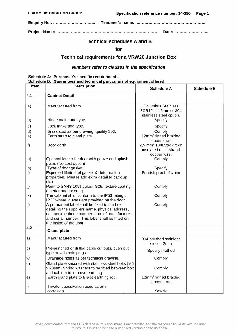
Technical schedules A and B for
Technical requirements for a VRW20 Junction Box
Numbers refer to clauses in the specification
Schedule A: Purchaser's specific requirements Schedule B: Guarantees and technical particulars of equipment offered
Item Description Schedule A Schedule B
4.1 Cabinet Detail
a) Manufactured from Columbus Stainless 3CR12 – 1.6mm or 304 stainless steel option.
b) Hinge make and type. Specify c) Lock make and type. Specify d) Brass stud as per drawing, quality 303. Comply e) Earth strap to gland plate . 12mm2 tinned braided
copper strap.
f) Door earth. 2,5 mm2 1000Vac green insulated multi-strand
copper wire.
g) Optional louver for door with gauze and splash plate. (No cost option)
Comply
h) Type of door gasket. Specify i) Expected lifetime of gasket & deformation
properties. Please add extra detail to back up claim.
Furnish proof of claim
j) Paint to SANS 1091 colour G29, texture coating (interior and exterior)
Comply
k) The cabinet shall conform to the IP53 rating or IP33 where louvres are provided on the door
Comply
l) A permanent label shall be fixed to the box detailing the suppliers name, physical address, contact telephone number, date of manufacture and serial number. This label shall be fitted on the inside of the door.
Comply
4.2 Gland plate
a) Manufactured from 304 brushed stainless steel – 2mm
b) Pre-punched or drilled cable cut outs, push out type or with hole plugs. Specify method
c) Drainage holes as per technical drawing. Comply d) Gland plate secured with stainless steel bolts (M6
x 20mm) Spring washers to be fitted between bolt and cabinet to improve earthing.
Comply
e) Earth gland plate to Brass earthing rod. 12mm2 tinned braided copper strap.
f) Trivalent passivation used as anti corrosion
Yes/No

ESKOM DISTRIBUTION GROUP Specification reference number: 34-396 Page 2 Enquiry No.: …………………………..
Tenderer’s name: ……………………………………………..
Project Name: ………………………………………………………………….
Date: ……………………..
Technical schedules A and B (Continued)
Item Description Schedule A Schedule B
4.3 Insert tray
4.3.1 General requirements
a) Manufactured from Columbus Stainless 3CR12, 2mm or 304 stainless steel option.
b) Tray mounted on M6 x 25mm stainless steel stud, spring washer and bolt.
Comply
c) Paint specification to SCSSCAAP9, SANS 1091 white, smooth coating.
Comply
d) Earth insert tray to brass earthing rod. 12mm2 tinned braided copper strap.
4.3.2 Terminals
a) Type of mounting Rail
b) Manufacturer and type 10mm Screw clamp, spring loaded terminal in accordance with 34-253 (to Eskom approval)
4.3.3 Wiring
a) Wire thickness mm2 2.5 b) Type of termination Crimped lug c) Manufacturer (To Eskom approval) In accordance with
ESKASAAO4 (to Eskom approval)
d) Wiring identification By slip-on ferrule. All wiring done by hand inside and outside module is to be labelled on both ends.
e) Manufacturer (To Eskom approval) Specify f) Trunking of dimensions 40mm x 60mm to
be supplied except for the VT insert (Section 4.3.5.5) where 40mm x 40mm trunking will be used.
Comply
4.3.4 Miniature Circuit breakers
a) Manufacturer (To Eskom approval) Merlin Gerin Multi 9 C60 single pole or approved equivalent
b) Rating A 10
c) Curve C
d) Breaking capacity kA 3

ESKOM DISTRIBUTION GROUP Specification reference number: 34-396 Page 3 Enquiry No.: …………………………..
Tenderer’s name: ……………………………………………..
Project Name: ………………………………………………………………….
Date: ……………………..
Technical schedules A and B (Continued)
Item Description Schedule A Schedule B
4.3.5 Insert variants
a) All five stipulated options to be offered Comply
4.4 Corrosion protection
a) Preparation of surfaces In accordance with SCSSCAAP9 DS6 and
DS11
b) Primer coat In accordance with SCSSCAAP9 DS6 and
DS11
i) manufacturer
ii) type
c) Under coat In accordance with SCSSCAAP9 DS6 and
DS11
i) manufacturer
ii) type
d) Finishing coat In accordance with SCSSCAAP9 DS6 and
DS11
i) manufacturer
ii) type
6. Labelling, packaging, marking and transport
6.1.1 Labels
a) Junction box labelled as per Section 6.1.1
Comply
6.1.2 Packaging
a) Corrugated cardboard covering with plastic wrap.
Comply
6.1.3 Marking
a) Package to be marked as per Section 6.1.3
Comply
6.1.4 Transport
a) As per 10.2 with itemised cost per range.
Specify
b) Local delivery “free” Comply
Related Documents


