Bitec 2008 Bitec Bitec Bitec Bitec DSP Solutions for Industry & Research CIII VDK Picture-in-Picture (PiP) 8.1 Reference Design Version 0.1

Welcome message from author
This document is posted to help you gain knowledge. Please leave a comment to let me know what you think about it! Share it to your friends and learn new things together.
Transcript
Bitec 2008
Bitec Bitec Bitec Bitec DSP Solutions for Industry & Research
CIII VDK Picture-in-Picture (PiP) 8.1
Reference Design
Version 0.1
Page 2
Bitec 2008
Revision history ........................................................................ 3
Introduction ............................................................................ 4
Installation .............................................................................. 6
Building the demo software .......................................................... 6
Page 3
Bitec 2008
Revision history
Version Comment
V0.1 Beta release

Page 4
Bitec 2008
Introduction
Found primarily on more expensive televisions, PIP lets you watch a second video
stream in a little window. More-elaborate versions can resize the window, move
it around the screen, create still or multiple still images, or simply divide the
screen into two same-size pictures, often called 'picture-outside-picture' (POP).
This reference design demonstrates the use of the Bitec CIII VDK for picture-in-
picture on 1080P Full HD video signals. The four composite/s-video channel are
combined with a Full HD 1080P video stream to generate a 1080P, PiP output
video stream. The resulting image stream is the combination of all five input
video signals.
A block diagram of the SoPC is shown in Figure 1. Both the input video signals are
triple frame buffered to allow synchronization to the output video stream driven
by the local 134Mhz pixel clock.
NTSC/PAL
input
NTSC/PAL
To
800x600PNTSC/PAL
input
NTSC/PAL
To
800x600PNTSC/PAL
input
NTSC/PAL
To
800x600P
Bottom Bank
SDRAM
DVI
Input
1080P
Triple Frame
Buffer
Mixer
Top Bank
SDRAM
DVI
Output
1080P
CIII
PLL
Local video
clock
(134 Mhz)
NTSC/PAL
input
NTSC/PAL
To
800x600P
Nios II
Figure 1 Picture-in-picture block diagram
Page 5
Bitec 2008
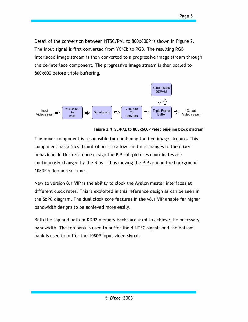
Detail of the conversion between NTSC/PAL to 800x600P is shown in Figure 2.
The input signal is first converted from YCrCb to RGB. The resulting RGB
interlaced image stream is then converted to a progressive image stream through
the de-interlace component. The progressive image stream is then scaled to
800x600 before triple buffering.
YCrCb422to
RGB
De-interlaceTriple Frame
Buffer
Bottom Bank
SDRAM
Input
Video stream
Output
Video stream
720x480To
800x600
Figure 2 NTSC/PAL to 800x600P video pipeline block diagram
The mixer component is responsible for combining the five image streams. This
component has a Nios II control port to allow run time changes to the mixer
behaviour. In this reference design the PiP sub-pictures coordinates are
continuously changed by the Nios II thus moving the PiP around the background
1080P video in real-time.
New to version 8.1 VIP is the ability to clock the Avalon master interfaces at
different clock rates. This is exploited in this reference design as can be seen in
the SoPC diagram. The dual clock core features in the v8.1 VIP enable far higher
bandwidth designs to be achieved more easily.
Both the top and bottom DDR2 memory banks are used to achieve the necessary
bandwidth. The top bank is used to buffer the 4-NTSC signals and the bottom
bank is used to buffer the 1080P input video signal.
Page 6
Bitec 2008
Installation
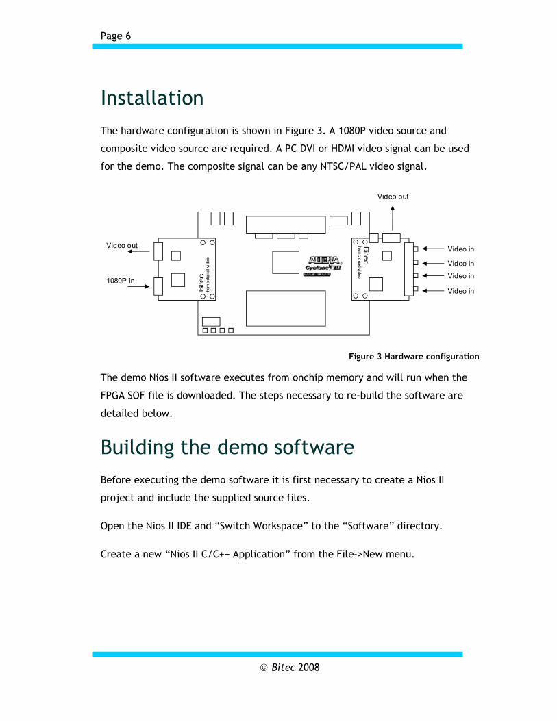
The hardware configuration is shown in Figure 3. A 1080P video source and
composite video source are required. A PC DVI or HDMI video signal can be used
for the demo. The composite signal can be any NTSC/PAL video signal.
Bitec
hsmc digital video
Bitec
hsmc quad video
Video out
1080P in
Video in
Video in
Video in
Video in
Video out
Figure 3 Hardware configuration
The demo Nios II software executes from onchip memory and will run when the
FPGA SOF file is downloaded. The steps necessary to re-build the software are
detailed below.
Building the demo software
Before executing the demo software it is first necessary to create a Nios II
project and include the supplied source files.
Open the Nios II IDE and “Switch Workspace” to the “Software” directory.
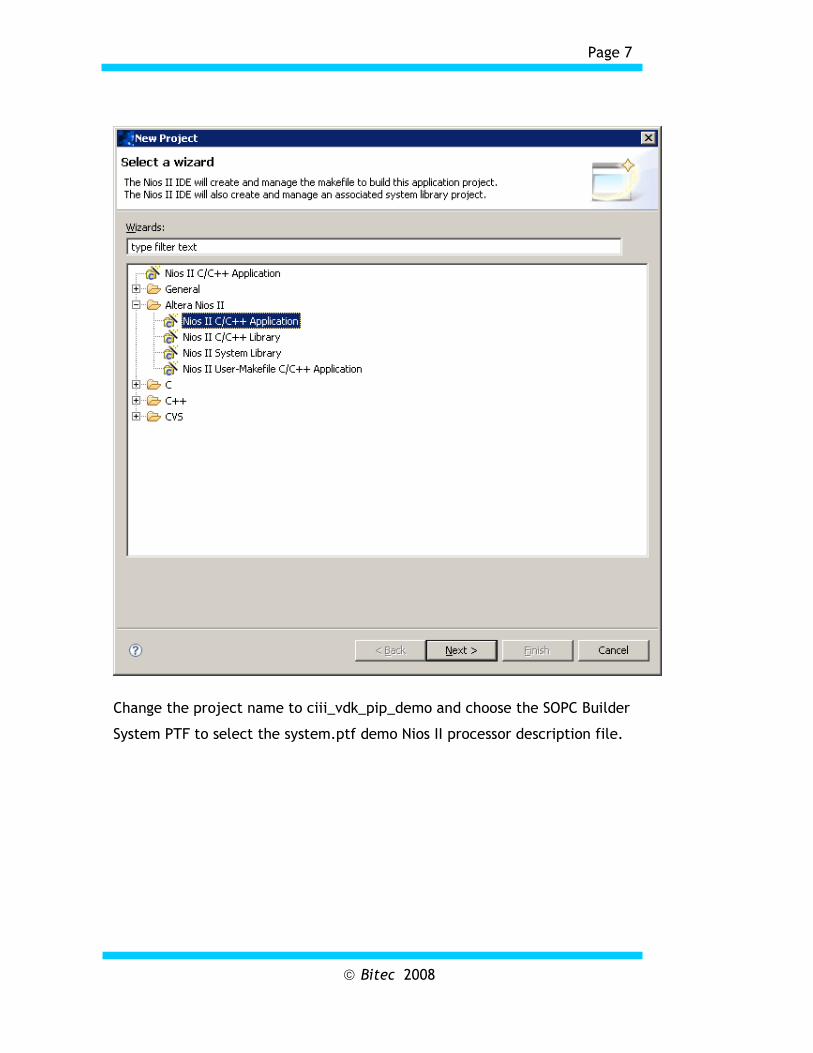
Create a new “Nios II C/C++ Application” from the File->New menu.
Page 7
Bitec 2008
Change the project name to ciii_vdk_pip_demo and choose the SOPC Builder
System PTF to select the system.ptf demo Nios II processor description file.

Page 8
Bitec 2008
Click “Next” and then “Finish”. Two directories will be created below the
Software directory.
Copy the supplied source files into the newly created “ciii_vdk_pip_demo”
directory.
Highlight the ciii_vdk_pip_demo directory in “Project Browser” pane “Refresh”
using F5 or File->Refresh.

Page 9
Bitec 2008
Select the auto generated hello_world.c and delete.
Before building, set the memory options to “onchip_mem” in the system library
properties. Also select the “Reduced Drivers” and “Small C Library” options.
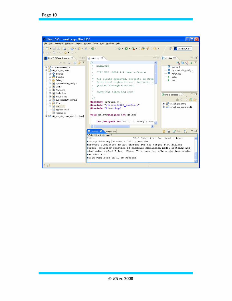
The project is now ready for build and debug.
Page 10
Bitec 2008
Page 11
Bitec 2008
Bitec 1 Angelsea Mead Chippenham, Wilts United Kingdom Tel. +44-(0) 797-964-5514 Fax +44-(0) 871-661-0229 E-mail: [email protected] Internet: www.bitec-dsp.com
All information and data contained in this data sheet are without any commitment, are not to be considered as an offer for conclusion of a contract, nor shall they be construed as to create any liability. Any new issue of this data sheet invalidates previous issues. Product availability and delivery are exclusively subject to our respective order confirmation form; the same applies to orders based on development samples delivered. By this publication, BiTEC does not assume responsibility for patent infringements or other rights of third parties, which may result from its use. Further, BiTEC reserves the right to revise this publication and to make changes to its content, at any time, without obligation to notify any person or entity of such revisions or changes. No part of this publication may be reproduced, photocopied, stored on a retrieval system, or transmitted without the express written consent of BiTEC.
Altera, MegaCore and the Altera and Cyclone logos are Reg. U.S. Pat. & Tm. Off. and marks of Altera in and outside the US.
Related Documents