BenF V3 firmware users guide for Seeed Studio DSO Nano V1 and V2 Page 1 of 19 2011.05.19 V3.6 Revision 3 BenF V3 firmware users guide DSO Nano V1 DSO Nano V2

Welcome message from author
This document is posted to help you gain knowledge. Please leave a comment to let me know what you think about it! Share it to your friends and learn new things together.
Transcript
BenF V3 firmware users guide for
Seeed Studio DSO Nano V1 and V2
Page 1 of 19 2011.05.19 V3.6 Revision 3
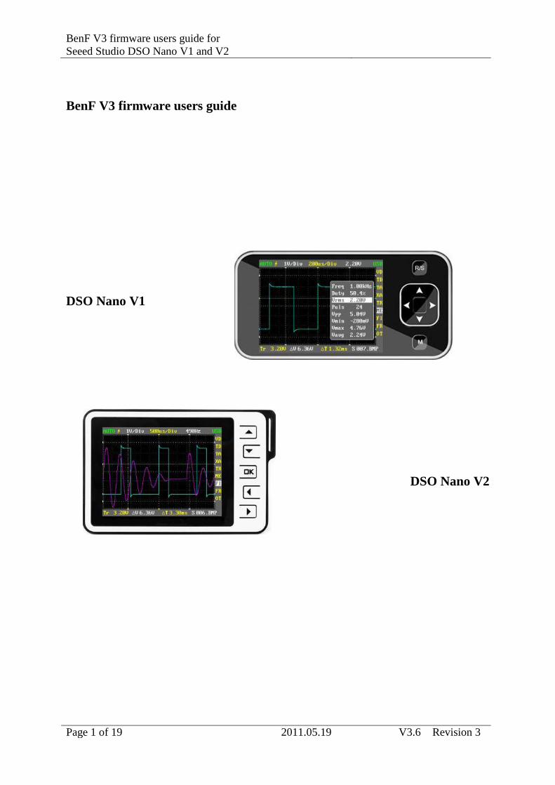
BenF V3 firmware users guide
DSO Nano V1
DSO Nano V2
Page 2 of 19 2011.05.19 V3.6 Revision 3
Introduction
The BenF V3 firmware has been developed to overcome some of the limitations and issues
with the official firmware releases. In particular this applies to improved SD card support, a
more advanced no loss sampling algorithm and a more intuitive user interface. The firmware
is designed to run on Seeed Studio DSO Nano V1 and V2 hardware. It may or may not work
with hardware supplied by other manufacturers.
The firmware is free of charge to individuals in its binary format and is put into the public
domain in the hope that it will be useful for others and not only the author. Any use of this
firmware is at your own risk. No express or implied warranty is granted for the firmware or
related documentation and under no circumstance can the author be held responsible for any
direct or consequential damage that may arise from using it.
Background
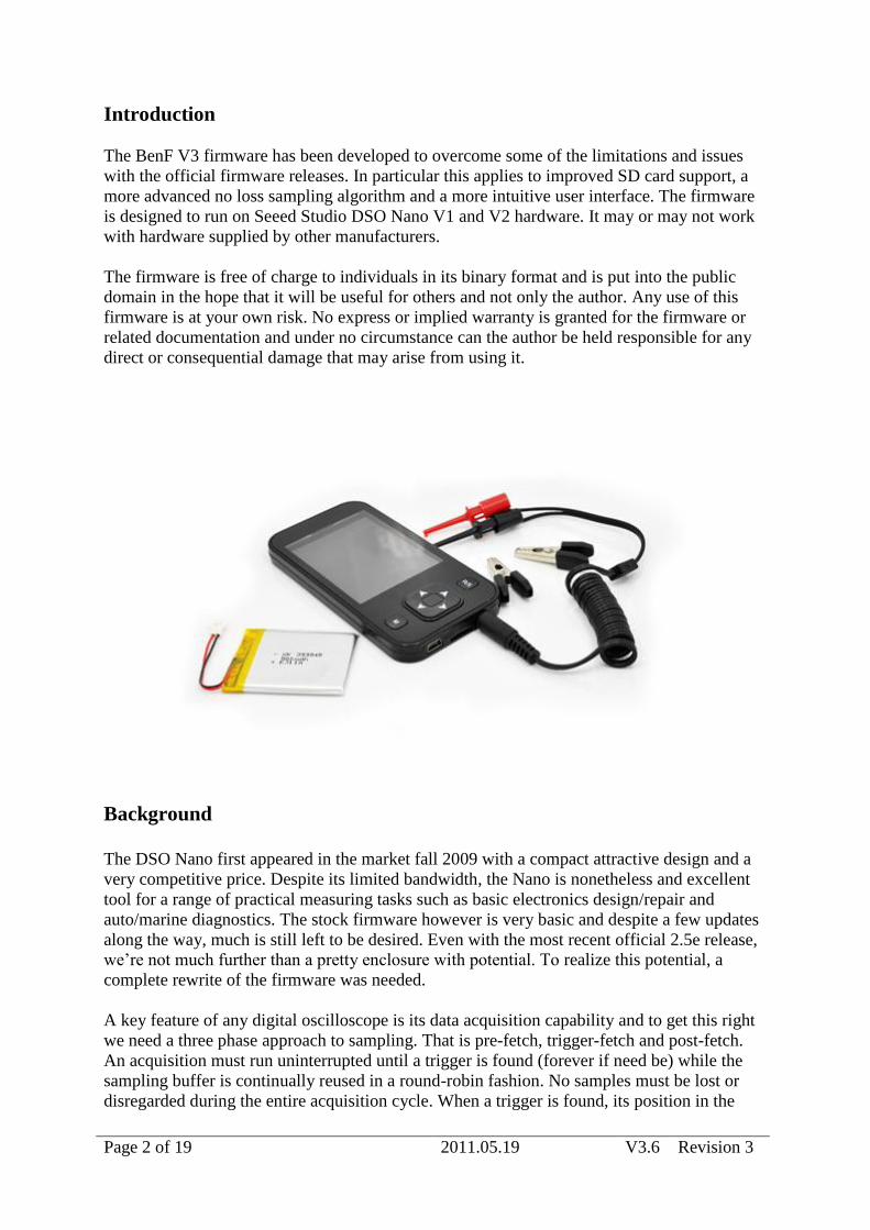
The DSO Nano first appeared in the market fall 2009 with a compact attractive design and a
very competitive price. Despite its limited bandwidth, the Nano is nonetheless and excellent
tool for a range of practical measuring tasks such as basic electronics design/repair and
auto/marine diagnostics. The stock firmware however is very basic and despite a few updates
along the way, much is still left to be desired. Even with the most recent official 2.5e release,
we’re not much further than a pretty enclosure with potential. To realize this potential, a
complete rewrite of the firmware was needed.
A key feature of any digital oscilloscope is its data acquisition capability and to get this right
we need a three phase approach to sampling. That is pre-fetch, trigger-fetch and post-fetch.
An acquisition must run uninterrupted until a trigger is found (forever if need be) while the
sampling buffer is continually reused in a round-robin fashion. No samples must be lost or
disregarded during the entire acquisition cycle. When a trigger is found, its position in the

Page 3 of 19 2011.05.19 V3.6 Revision 3
buffer is marked and acquisition continues until the entire sampling buffer is filled with data.
The data from this acquisition cycle is then displayed with the trigger point centered on the
screen.
The official DSO Nano firmware is using the simplistic single phase acquisition model. That
is start acquisition, stop acquisition and then search for a trigger. An issue with this approach
is that the trigger (the data of interest) may arrive while we’re not acquiring data and so will
be lost. This makes it more or less unfit for digital analysis (e.g. SPI, I2C, RS-232, RS-485)
and also of limited use for signals like electronic ignition (narrow, infrequent pulses) and
many (if not most) other real life measuring and fault finding challenges.
Page 4 of 19 2011.05.19 V3.6 Revision 3
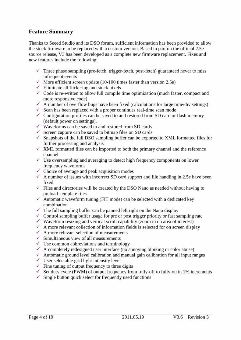
Feature Summary
Thanks to Seeed Studio and its DSO forum, sufficient information has been provided to allow
the stock firmware to be replaced with a custom version. Based in part on the official 2.5e
source release, V3 has been developed as a complete new firmware replacement. Fixes and
new features include the following:
Three phase sampling (pre-fetch, trigger-fetch, post-fetch) guaranteed never to miss
infrequent events
More efficient screen update (10-100 times faster than version 2.5e)
Eliminate all flickering and stuck pixels
Code is re-written to allow full compile time optimization (much faster, compact and
more responsive code)
A number of overflow bugs have been fixed (calculations for large time/div settings)
Scan has been replaced with a proper continues real-time scan mode
Configuration profiles can be saved to and restored from SD card or flash memory
(default power on settings).
Waveforms can be saved to and restored from SD cards
Screen capture can be saved to bitmap files on SD cards
Snapshots of the full DSO sampling buffer can be exported to XML formatted files for
further processing and analysis
XML formatted files can be imported to both the primary channel and the reference
channel
Use oversampling and averaging to detect high frequency components on lower
frequency waveforms
Choice of average and peak acquisition modes
A number of issues with incorrect SD card support and file handling in 2.5e have been
fixed
Files and directories will be created by the DSO Nano as needed without having to
preload template files
Automatic waveform tuning (FIT mode) can be selected with a dedicated key
combination
The full sampling buffer can be panned left right on the Nano display
Control sampling buffer usage for pre or post trigger priority or fast sampling rate
Waveform resizing and vertical scroll capability (zoom in on area of interest)
A more relevant collection of information fields is selected for on screen display
A more relevant selection of measurements
Simultaneous view of all measurements
Use common abbreviations and terminology
A completely redesigned user interface (no annoying blinking or color abuse)
Automatic ground level calibration and manual gain calibration for all input ranges
User selectable grid light intensity level
Fine tuning of output frequency to three digits
Set duty cycle (PWM) of output frequency from fully-off to fully-on in 1% increments
Single button quick select for frequently used functions
Page 5 of 19 2011.05.19 V3.6 Revision 3
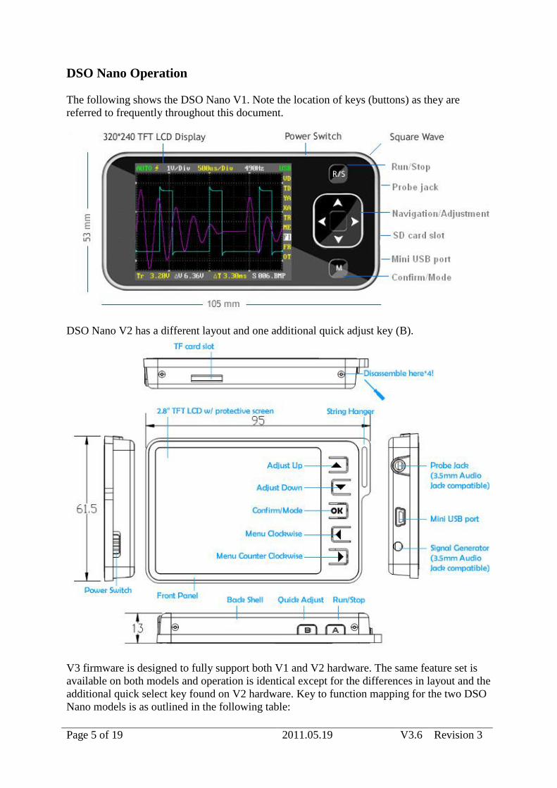
DSO Nano Operation
The following shows the DSO Nano V1. Note the location of keys (buttons) as they are
referred to frequently throughout this document.
DSO Nano V2 has a different layout and one additional quick adjust key (B).
V3 firmware is designed to fully support both V1 and V2 hardware. The same feature set is
available on both models and operation is identical except for the differences in layout and the
additional quick select key found on V2 hardware. Key to function mapping for the two DSO
Nano models is as outlined in the following table:
Page 6 of 19 2011.05.19 V3.6 Revision 3
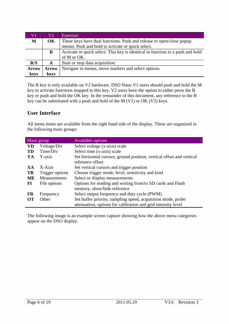
V1 V2 Function
M OK These keys have dual functions. Push and release to open/close popup
menus. Push and hold to activate or quick select.
B Activate or quick select. This key is identical in function to a push and hold
of M or OK.
R/S A Start or stop data acquisition.
Arrow
keys
Arrow
keys
Navigate in menus, move markers and select options.
The B key is only available on V2 hardware. DSO Nano V1 users should push and hold the M
key to activate functions mapped to this key. V2 users have the option to either press the B
key or push and hold the OK key. In the remainder of this document, any reference to the B
key can be substituted with a push and hold of the M (V1) or OK (V2) keys.
User Interface
All menu items are available from the right hand side of the display. These are organized in
the following main groups:
Main group Available options
VD Voltage/Div Select voltage (y-axis) scale
TD Time/Div Select time (x-axis) scale
YA Y-axis Set horizontal cursors, ground position, vertical offset and vertical
reference offset
XA X-Axis Set vertical cursors and trigger position
TR Trigger options Choose trigger mode, level, sensitivity and kind
ME Measurements Select or display measurements
FI File options Options for reading and writing from/to SD cards and Flash
memory, show/hide reference
FR Frequency Select output frequency and duty cycle (PWM)
OT Other Set buffer priority, sampling speed, acquisition mode, probe
attenuation, options for calibration and grid intensity level
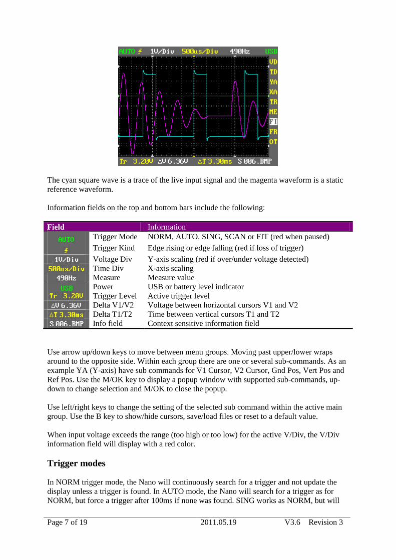
The following image is an example screen capture showing how the above menu categories
appear on the DSO display.
Page 7 of 19 2011.05.19 V3.6 Revision 3
The cyan square wave is a trace of the live input signal and the magenta waveform is a static
reference waveform.
Information fields on the top and bottom bars include the following:
Field Information
Trigger Mode NORM, AUTO, SING, SCAN or FIT (red when paused)
Trigger Kind Edge rising or edge falling (red if loss of trigger)
Voltage Div Y-axis scaling (red if over/under voltage detected)
Time Div X-axis scaling
Measure Measure value
Power USB or battery level indicator
Trigger Level Active trigger level
Delta V1/V2 Voltage between horizontal cursors V1 and V2
Delta T1/T2 Time between vertical cursors T1 and T2
Info field Context sensitive information field
Use arrow up/down keys to move between menu groups. Moving past upper/lower wraps
around to the opposite side. Within each group there are one or several sub-commands. As an
example YA (Y-axis) have sub commands for V1 Cursor, V2 Cursor, Gnd Pos, Vert Pos and
Ref Pos. Use the M/OK key to display a popup window with supported sub-commands, up-
down to change selection and M/OK to close the popup.
Use left/right keys to change the setting of the selected sub command within the active main
group. Use the B key to show/hide cursors, save/load files or reset to a default value.
When input voltage exceeds the range (too high or too low) for the active V/Div, the V/Div
information field will display with a red color.
Trigger modes
In NORM trigger mode, the Nano will continuously search for a trigger and not update the
display unless a trigger is found. In AUTO mode, the Nano will search for a trigger as for
NORM, but force a trigger after 100ms if none was found. SING works as NORM, but will
Page 8 of 19 2011.05.19 V3.6 Revision 3
not initiate a new acquisition cycle after a successful trigger. Use the A key (R/S on V1) to
start a new SING cycle.
Choose “Tr. Mode” (Trigger Mode) and press B to activate (or deactivate) FIT mode. In FIT
trigger mode, the Nano will automatically identify the type of waveform and adjust the
settings to produce a usable display of the input signal. This is similar in function to the Auto
push button found on most scopes. The function will track the input signal and continuously
adjust trigger level, ground level, V/Div and T/Div in small steps until a stable waveform can
be displayed. Manually adjusting trigger level, V/Div or T/Div when in FIT trigger mode will
revert to AUTO mode. A stable repeating input signal must be present for this function to
work well.
Choose AUTO trigger mode and T/Div greater or equal to 100ms to activate real-time scan.
In SCAN mode, data acquisition runs continuously and the input signal is progressively
displayed from left to right in real-time disregarding other trigger options. This mode is useful
for observing or trending a slow changing signal such as temperature variations or battery
charge level.
No trigger found is indicated with the trigger kind (rising/falling) symbol displayed in the
color red.
When acquisitions are stopped, trigger mode is displayed with the color red.
Use menu option “Tr.Kind” (Trigger Kind) to select rising or falling edge trigger, “Tr. Level”
to set trigger level and “Tr. Sens” to set trigger sensitivity.
Panning the full sampling buffer
Panning left/right is possible through menu item XA (X axis) and sub option “Trig Pos”
(Trigger Position). With the left/right keys, you offset the trigger position in steps of 1
horizontal div. When using this technique, you can pan left/right to view the full sampling
buffer (more than 13 full screens). When panning left/right, pressing B will reset trigger point
back to center. When at center, this key will alternately show/hide the trigger position axis. To
stop capture, you can use either SING trigger mode or use NORM/AUTO in combination
with the A key (R/S on V1).
Empty areas far left and far right, represent time before and after the acquisition period. The
size of these areas will change between acquisition cycles subject to the position where the
trigger was found. Irrespective of empty areas, acquired data will always span the full
capacity of the sampling buffer.
Resizing and zooming
A captured (stopped) waveform can be resized (zoomed in/out) through altering V/Div and/or
T/Div. V/Div will either stretch or compress a waveform in the vertical dimension whereas
T/Div will allow you to stretch/compress a waveform in the horizontal dimension. This
feature applies to data currently in the sampling buffer (static data). Once acquisitions are
restarted (using the A key), new data will be sampled using the currently active V/Div and
T/Div selections.
Page 9 of 19 2011.05.19 V3.6 Revision 3
Use menu item YA and sub option “Vert Pos” to scroll a waveform vertically. The left/right
keys will offset vertical position of the displayed waveform in steps of 1 vertical div. This
feature can be used with acquisitions running (live data) or stopped (static data). Pressing B
with “Vert Pos” selected, will reset vertical offset back to zero.
Note that sampling an input signal with a high gain (low V/Div selection) may lead to
distorted waveforms (flattened top and/or bottom) and inaccurate measurements. This is the
case when the input voltage level exceeds the min/max levels for the selected V/Div. The
Nano will check for this condition and display the V/div selection with a red color as a
voltage out of range warning. Color will revert to normal (white), when V/Div is increased
and/or the input voltage drops to within min/max for the selected V/Div.
Page 10 of 19 2011.05.19 V3.6 Revision 3
Buffer priority and sampling speed
Use menu OT and sub option “Buffer Pri” to switch between buffer priority modes equal and
post. In equal priority mode, an even split is used for waveform data before and after the
trigger point. In post priority mode, maximum buffer capacity will be used for data after the
trigger.
Trigger position will default to the center of the display when using priority mode equal. In
post priority mode, trigger position will default to the left side in order to fit more post trigger
data on screen. Sub option “Trig Pos” (menu XA) can be used to further adjust trigger
position.
Use sub option “Smpl Speed” to switch between normal and fast sampling mode. In fast
sampling mode, sampling rate (Sa/s) is increased at the expense of reduced sampling depth.
This mode will improve resolution and accuracy for time related measurements (frequency,
duty cycle and pulse width) of lower frequency signals. Fast sampling mode can also be used
to reduce time between measurement updates (increase refresh rate) and to detect high
frequency components on low frequency waveforms.
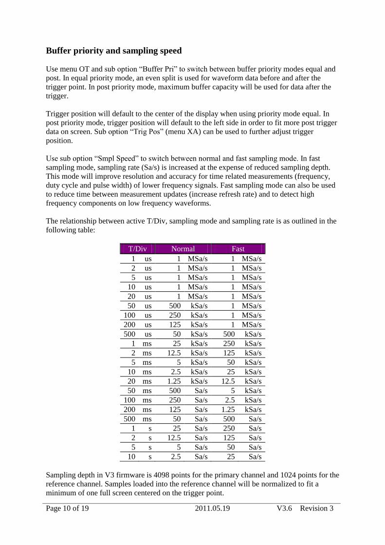
The relationship between active T/Div, sampling mode and sampling rate is as outlined in the
following table:
T/Div Normal Fast
1 us 1 MSa/s 1 MSa/s
2 us 1 MSa/s 1 MSa/s
5 us 1 MSa/s 1 MSa/s
10 us 1 MSa/s 1 MSa/s
20 us 1 MSa/s 1 MSa/s
50 us 500 kSa/s 1 MSa/s
100 us 250 kSa/s 1 MSa/s
200 us 125 kSa/s 1 MSa/s
500 us 50 kSa/s 500 kSa/s
1 ms 25 kSa/s 250 kSa/s
2 ms 12.5 kSa/s 125 kSa/s
5 ms 5 kSa/s 50 kSa/s
10 ms 2.5 kSa/s 25 kSa/s
20 ms 1.25 kSa/s 12.5 kSa/s
50 ms 500 Sa/s 5 kSa/s
100 ms 250 Sa/s 2.5 kSa/s
200 ms 125 Sa/s 1.25 kSa/s
500 ms 50 Sa/s 500 Sa/s
1 s 25 Sa/s 250 Sa/s
2 s 12.5 Sa/s 125 Sa/s
5 s 5 Sa/s 50 Sa/s
10 s 2.5 Sa/s 25 Sa/s
Sampling depth in V3 firmware is 4098 points for the primary channel and 1024 points for the
reference channel. Samples loaded into the reference channel will be normalized to fit a
minimum of one full screen centered on the trigger point.
Page 11 of 19 2011.05.19 V3.6 Revision 3
Acquisition display modes
Use menu OT and sub option “Disp Mode” to switch between average and peak display
mode. This mode determines how the input waveform amplitude will be displayed for
oversampled signals.
Peak mode will identify the minimum and maximum values in your input signal and use these
when displaying the waveform. This can be useful when looking for higher frequency
components (such as noise or narrow pulses) present in your input signal. Noise will appear
more dominant in this mode.
Average can be used to reduce random noise from a displayed waveform. This may be
preferred when the larger dominant waveform (such as a logic square wave) is your target of
interest. Note that narrow pulses may appear with significantly reduced amplitude in this
mode.
Exported XML data is not affected by this setting.
Page 12 of 19 2011.05.19 V3.6 Revision 3
Profiles and power on defaults
Preferences can be saved to a micro-SD card for recall or to flash memory to act as power on
defaults. First, use the various menu options to configure DSO Nano any way you prefer.
Then choose menu FI and sub-option "Save Pro". Choose profile <S Flash> (using left/right
keys) and press the B key (a confirmation will be displayed in the information field when save
is complete). This will save all active settings to DSO internal flash memory for use as power
on defaults. Profiles with a sequential number (e.g. S 001.CFG ) will be saved to your SD
card.
Select sub-option "Load Pro", choose a profile (using left/right keys) and press the B key to
load from flash memory or SD card. Choose profile <L Factory> and press the B key to reset
the Nano to factory defaults. This will reset active preferences and gain calibration to default
values. Use save to flash (sub options “S Flash” and “Save Cal”) to use these values as power
on defaults.
Page 13 of 19 2011.05.19 V3.6 Revision 3
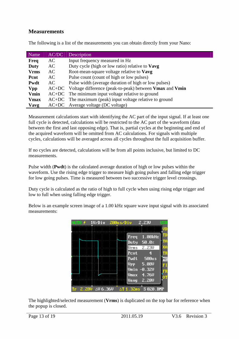
Measurements
The following is a list of the measurements you can obtain directly from your Nano:
Name AC/DC Description
Freq AC Input frequency measured in Hz
Duty AC Duty cycle (high or low ratio) relative to Vavg
Vrms AC Root-mean-square voltage relative to Vavg
Pcnt AC Pulse count (count of high or low pulses)
Pwdt AC Pulse width (average duration of high or low pulses)
Vpp AC+DC Voltage difference (peak-to-peak) between Vmax and Vmin
Vmin AC+DC The minimum input voltage relative to ground
Vmax AC+DC The maximum (peak) input voltage relative to ground
Vavg AC+DC Average voltage (DC voltage)
Measurement calculations start with identifying the AC part of the input signal. If at least one
full cycle is detected, calculations will be restricted to the AC part of the waveform (data
between the first and last opposing edge). That is, partial cycles at the beginning and end of
the acquired waveform will be omitted from AC calculations. For signals with multiple
cycles, calculations will be averaged across all cycles throughout the full acquisition buffer.
If no cycles are detected, calculations will be from all points inclusive, but limited to DC
measurements.
Pulse width (Pwdt) is the calculated average duration of high or low pulses within the
waveform. Use the rising edge trigger to measure high going pulses and falling edge trigger
for low going pulses. Time is measured between two successive trigger level crossings.
Duty cycle is calculated as the ratio of high to full cycle when using rising edge trigger and
low to full when using falling edge trigger.
Below is an example screen image of a 1.00 kHz square wave input signal with its associated
measurements:
The highlighted/selected measurement (Vrms) is duplicated on the top bar for reference when
the popup is closed.
Page 14 of 19 2011.05.19 V3.6 Revision 3
Select menu ME and press the B key to save a screen capture to your micro-SD card with
overlaid measurements.
Page 15 of 19 2011.05.19 V3.6 Revision 3
Frequency Generator
The signal generator will output a square wave that can be used for test purposes (refer to the
section on “DSO Nano Operation” for information on where the test signal output connector
is located on your Nano). Output swing is from ground to the internal DSO lithium battery
level. The output signal will peak (logic high level) at just above 3V for a near empty battery
to 4.3V for a fully charged or charging battery. Peak-to-peak voltage (Vpp) may rise slightly
above battery level due to a small undershoot (falling edge) and overshoot (rising edge) on the
output square wave. Output level amplitude can not be altered.
Signal generator output frequency and duty cycle can be controlled as follows:
Output frequency can be set to three digits of precision in the range from 10Hz to 1MHz
using menu FR and sub option “Freq Out”. Press the B key to cycle between 1, 2 and 3 digits
of precision. Press left or right to alter the highlighted digit.
Duty cycle (pulse width modulation) can be set with sub option “Freq Duty” in steps of 1%
(using left or right keys) from fully off to fully on. Press the B key to reset duty cycle back to
the default 50%.
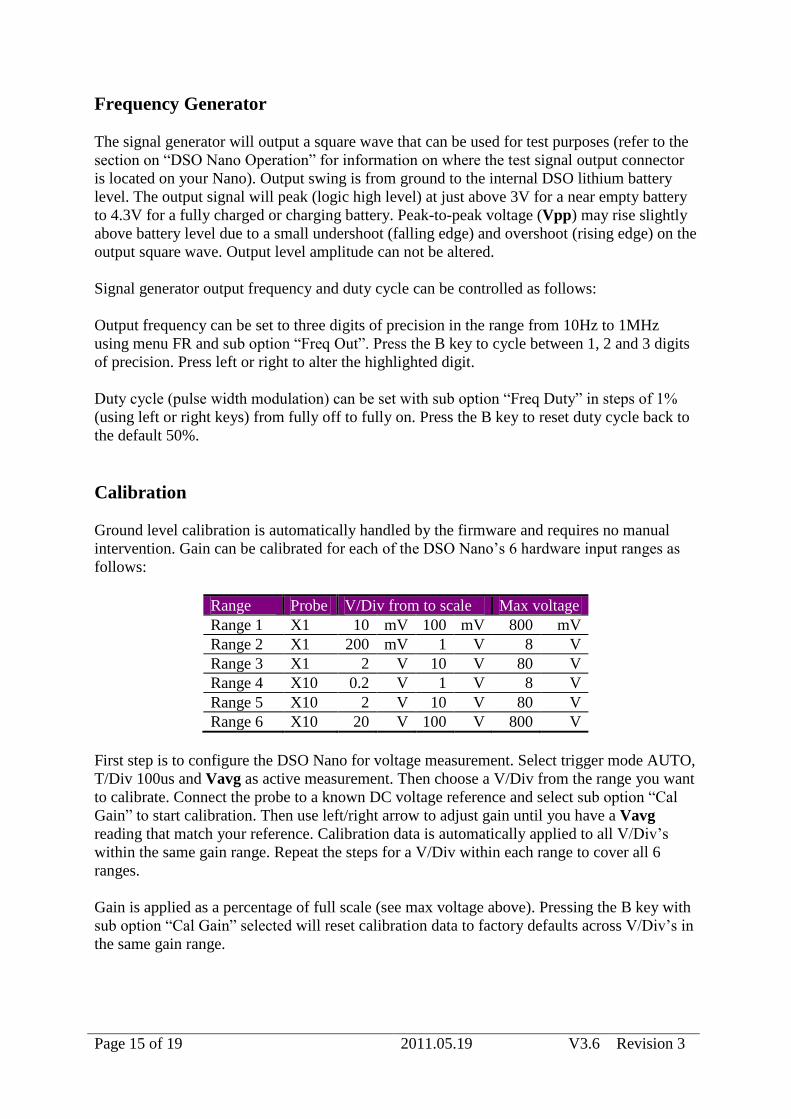
Calibration
Ground level calibration is automatically handled by the firmware and requires no manual
intervention. Gain can be calibrated for each of the DSO Nano’s 6 hardware input ranges as
follows:
Range Probe V/Div from to scale Max voltage
Range 1 X1 10 mV 100 mV 800 mV
Range 2 X1 200 mV 1 V 8 V
Range 3 X1 2 V 10 V 80 V
Range 4 X10 0.2 V 1 V 8 V
Range 5 X10 2 V 10 V 80 V
Range 6 X10 20 V 100 V 800 V
First step is to configure the DSO Nano for voltage measurement. Select trigger mode AUTO,
T/Div 100us and Vavg as active measurement. Then choose a V/Div from the range you want
to calibrate. Connect the probe to a known DC voltage reference and select sub option “Cal
Gain” to start calibration. Then use left/right arrow to adjust gain until you have a Vavg
reading that match your reference. Calibration data is automatically applied to all V/Div’s
within the same gain range. Repeat the steps for a V/Div within each range to cover all 6
ranges.
Gain is applied as a percentage of full scale (see max voltage above). Pressing the B key with
sub option “Cal Gain” selected will reset calibration data to factory defaults across V/Div’s in
the same gain range.
Page 16 of 19 2011.05.19 V3.6 Revision 3
Select sub option “Save Cal” and press B to save calibration data to FLASH (a confirmation
will be displayed in the information field once data has been saved). Calibration data saved to
FLASH will automatically be restored when you power on your Nano.
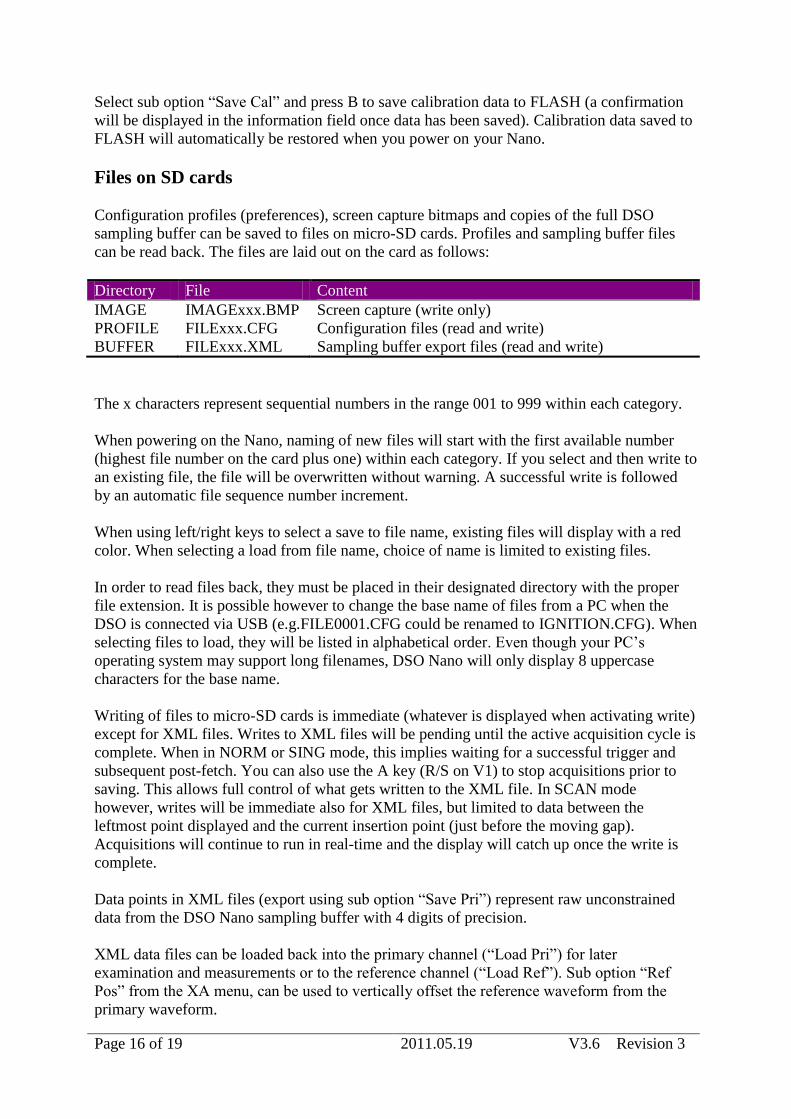
Files on SD cards
Configuration profiles (preferences), screen capture bitmaps and copies of the full DSO
sampling buffer can be saved to files on micro-SD cards. Profiles and sampling buffer files
can be read back. The files are laid out on the card as follows:
Directory File Content
IMAGE IMAGExxx.BMP Screen capture (write only)
PROFILE FILExxx.CFG Configuration files (read and write)
BUFFER FILExxx.XML Sampling buffer export files (read and write)
The x characters represent sequential numbers in the range 001 to 999 within each category.
When powering on the Nano, naming of new files will start with the first available number
(highest file number on the card plus one) within each category. If you select and then write to
an existing file, the file will be overwritten without warning. A successful write is followed
by an automatic file sequence number increment.
When using left/right keys to select a save to file name, existing files will display with a red
color. When selecting a load from file name, choice of name is limited to existing files.
In order to read files back, they must be placed in their designated directory with the proper
file extension. It is possible however to change the base name of files from a PC when the
DSO is connected via USB (e.g.FILE0001.CFG could be renamed to IGNITION.CFG). When
selecting files to load, they will be listed in alphabetical order. Even though your PC’s
operating system may support long filenames, DSO Nano will only display 8 uppercase
characters for the base name.
Writing of files to micro-SD cards is immediate (whatever is displayed when activating write)
except for XML files. Writes to XML files will be pending until the active acquisition cycle is
complete. When in NORM or SING mode, this implies waiting for a successful trigger and
subsequent post-fetch. You can also use the A key (R/S on V1) to stop acquisitions prior to
saving. This allows full control of what gets written to the XML file. In SCAN mode
however, writes will be immediate also for XML files, but limited to data between the
leftmost point displayed and the current insertion point (just before the moving gap).
Acquisitions will continue to run in real-time and the display will catch up once the write is
complete.
Data points in XML files (export using sub option “Save Pri”) represent raw unconstrained
data from the DSO Nano sampling buffer with 4 digits of precision.
XML data files can be loaded back into the primary channel (“Load Pri”) for later
examination and measurements or to the reference channel (“Load Ref”). Sub option “Ref
Pos” from the XA menu, can be used to vertically offset the reference waveform from the
primary waveform.
Page 17 of 19 2011.05.19 V3.6 Revision 3
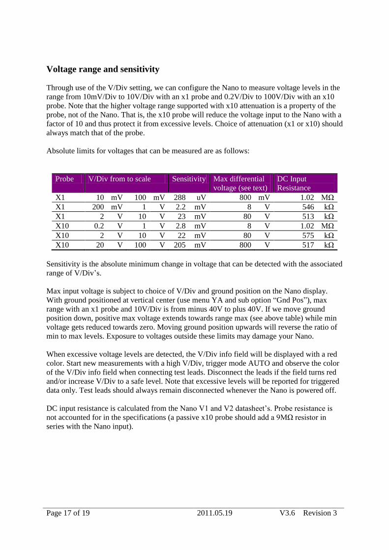
Voltage range and sensitivity
Through use of the V/Div setting, we can configure the Nano to measure voltage levels in the
range from 10mV/Div to 10V/Div with an x1 probe and 0.2V/Div to 100V/Div with an x10
probe. Note that the higher voltage range supported with x10 attenuation is a property of the
probe, not of the Nano. That is, the x10 probe will reduce the voltage input to the Nano with a
factor of 10 and thus protect it from excessive levels. Choice of attenuation (x1 or x10) should
always match that of the probe.
Absolute limits for voltages that can be measured are as follows:
Probe V/Div from to scale Sensitivity Max differential
voltage (see text)
DC Input
Resistance
X1 10 mV 100 mV 288 uV 800 mV 1.02 MΩ
X1 200 mV 1 V 2.2 mV 8 V 546 kΩ
X1 2 V 10 V 23 mV 80 V 513 kΩ
X10 0.2 V 1 V 2.8 mV 8 V 1.02 MΩ
X10 2 V 10 V 22 mV 80 V 575 kΩ
X10 20 V 100 V 205 mV 800 V 517 kΩ
Sensitivity is the absolute minimum change in voltage that can be detected with the associated
range of V/Div’s.
Max input voltage is subject to choice of V/Div and ground position on the Nano display.
With ground positioned at vertical center (use menu YA and sub option “Gnd Pos”), max
range with an x1 probe and 10V/Div is from minus 40V to plus 40V. If we move ground
position down, positive max voltage extends towards range max (see above table) while min
voltage gets reduced towards zero. Moving ground position upwards will reverse the ratio of
min to max levels. Exposure to voltages outside these limits may damage your Nano.
When excessive voltage levels are detected, the V/Div info field will be displayed with a red
color. Start new measurements with a high V/Div, trigger mode AUTO and observe the color
of the V/Div info field when connecting test leads. Disconnect the leads if the field turns red
and/or increase V/Div to a safe level. Note that excessive levels will be reported for triggered
data only. Test leads should always remain disconnected whenever the Nano is powered off.
DC input resistance is calculated from the Nano V1 and V2 datasheet’s. Probe resistance is
not accounted for in the specifications (a passive x10 probe should add a 9MΩ resistor in
series with the Nano input).
Page 18 of 19 2011.05.19 V3.6 Revision 3
Installation
The procedure to upgrade firmware is described in the manual that came with your DSO
Nano. A copy of this manual (PDF file) can also be downloaded from the Seeed Studio
product pages. You need to follow the steps in this procedure carefully and upload both the
DSO BenF APP v3.xx.dfu and DSO BenF LIB v3.xx.dfu files. The order of upload (LIB or
APP) is not significant.
Micro-SD cards must be formatted to use either the FAT16 or the FAT32 file system (NTFS
and exFAT are not supported). The newer model high capacity SD cards (SDHC) are not
supported. SD cards must support the SPI access protocol. The 2GB SanDisk card supplied by
Seeed Studio has been confirmed to work well with the new V3 firmware. The FAT16 file
system appears to be more responsive on Windows XP (e.g. when doing a directory refresh
from the PC after writing a new image file to the card). This may or may not be the case on
other platforms.
SD cards that have previously been formatted with the original Seeed Studio firmware must
be reformatted prior to use. A utility program called “sdformatter” (Google for a download
site) can be used to fully initialize a card to a known compatible format (sdformatter V2.9.0.5
was used for testing during development).
Page 19 of 19 2011.05.19 V3.6 Revision 3
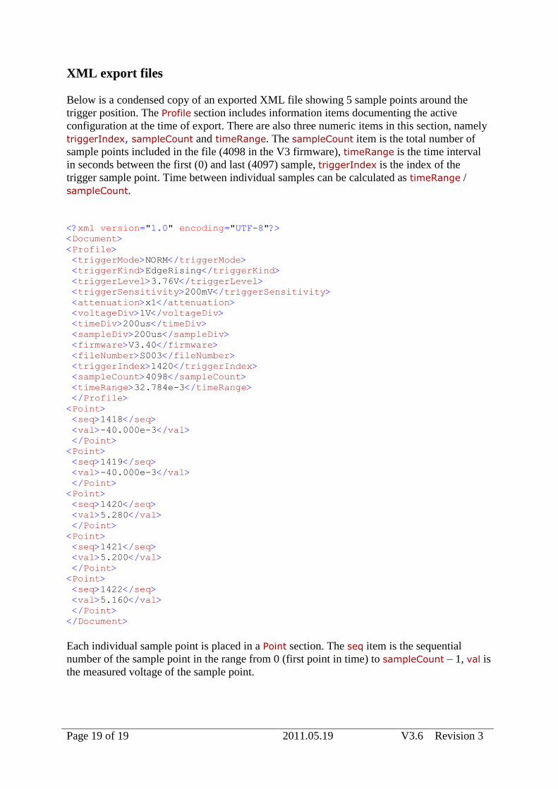
XML export files
Below is a condensed copy of an exported XML file showing 5 sample points around the
trigger position. The Profile section includes information items documenting the active
configuration at the time of export. There are also three numeric items in this section, namely
triggerIndex, sampleCount and timeRange. The sampleCount item is the total number of
sample points included in the file (4098 in the V3 firmware), timeRange is the time interval
in seconds between the first (0) and last (4097) sample, triggerIndex is the index of the
trigger sample point. Time between individual samples can be calculated as timeRange /
sampleCount.
<?xml version="1.0" encoding="UTF-8"?>
<Document>
<Profile>
<triggerMode>NORM</triggerMode>
<triggerKind>EdgeRising</triggerKind>
<triggerLevel>3.76V</triggerLevel>
<triggerSensitivity>200mV</triggerSensitivity>
<attenuation>x1</attenuation>
<voltageDiv>1V</voltageDiv>
<timeDiv>200us</timeDiv>
<sampleDiv>200us</sampleDiv>
<firmware>V3.40</firmware>
<fileNumber>S003</fileNumber>
<triggerIndex>1420</triggerIndex>
<sampleCount>4098</sampleCount>
<timeRange>32.784e-3</timeRange>
</Profile>
<Point>
<seq>1418</seq>
<val>-40.000e-3</val>
</Point>
<Point>
<seq>1419</seq>
<val>-40.000e-3</val>
</Point>
<Point>
<seq>1420</seq>
<val>5.280</val>
</Point>
<Point>
<seq>1421</seq>
<val>5.200</val>
</Point>
<Point>
<seq>1422</seq>
<val>5.160</val>
</Point>
</Document>
Each individual sample point is placed in a Point section. The seq item is the sequential
number of the sample point in the range from 0 (first point in time) to sampleCount – 1, val is
the measured voltage of the sample point.
Related Documents