1 SPECIFICATIONS Control Panel Specifications 21 zones including: • 16 fully programmable supervised zones (EOL resistors) • Supervised fire zone • 1 auxiliary normally open zone • 3 keypad activated zones Audible alarm output: • Bell output 700 mA, fused at 5 Amps, 12 VDC unregulated • Steady or pulsed output EEPROM memory: • Does not lose codes or system status on complete AC and battery failure Programmable output: • Transistor switch sinks 50 mA to ground • Operation controllable through program options Powerful 1.5 amp regulated power supply: • 400 mA auxiliary supply, 12 VDC unregulated • Separately fused for battery, keypad/auxiliary supply and bell output • Supervision for loss of AC power, low battery • Internal clock locked to AC power frequency Switched Smoke Detector Supply Output: • Controlled from keypad [✱][4] command Battery required: • 12 volt 4 Ah minimum rechargeable gel-cell or sealed lead-acid battery Transformer required: • 16.5 VAC, 40VA Dimensions: • 11" x 11.8" x 3.3" deep (279 x 300 x 84 mm) Weight: • 6.5 lbs (3 kg) Remote Keypad Specifications (PC3000RK) • Four wire (QUAD) hook-up and up to 3 keypads per system • Built-in piezoelectric buzzer • Full annunciation of zones and system status • Nominal current draw 60 mA • Dimensions 5.5" x 4.5" x 1" deep (140 x 114 x 25 mm) Output Voltage Specification Typically, with normal AC in and a fully charged battery, the output voltage will be 13.8 VDC. With AC off and a discharged battery, the voltage will go to 10 volts. Devices that require power from the control panel should be capable of normal operation over the voltage range of 10 to 14 VDC. Digital Communicator Specifications • 94 reporting codes • Transmits all 10BPS and 20BPS single line and extended formats • Radionics Rounds and Radionics Parity formats • Sescoa Superfast format • 3/1, 4/2 and hexadecimal numbers • DTMF and Pulse dialing • DPDT line seizure • True dial tone detection • Anti-jam feature • Two telephone numbers and two account codes • Split reporting of selected transmissions to each telephone number

Welcome message from author
This document is posted to help you gain knowledge. Please leave a comment to let me know what you think about it! Share it to your friends and learn new things together.
Transcript

1
SPECIFICATIONS
Control Panel Specifications21 zones including:
• 16 fully programmable supervised zones (EOL resistors)
• Supervised fire zone
• 1 auxiliary normally open zone• 3 keypad activated zones
Audible alarm output:
• Bell output700 mA, fused at 5 Amps, 12 VDC unregulated
• Steady or pulsed output
EEPROM memory:
• Does not lose codes or system status on complete ACand battery failure
Programmable output:
• Transistor switch sinks 50 mA to ground
• Operation controllable through program options
Powerful 1.5 amp regulated power supply:
• 400 mA auxiliary supply, 12 VDC unregulated• Separately fused for battery, keypad/auxiliary supply and
bell output• Supervision for loss of AC power, low battery
• Internal clock locked to AC power frequency
Switched Smoke Detector Supply Output:
• Controlled from keypad [Q][4] command
Battery required:
• 12 volt 4 Ah minimum rechargeable gel-cell or sealedlead-acid battery
Transformer required:
• 16.5 VAC, 40VA
Dimensions:
• 11" x 11.8" x 3.3" deep (279 x 300 x 84 mm)
Weight:
• 6.5 lbs (3 kg)
Remote Keypad Specifications(PC3000RK)
• Four wire (QUAD) hook-up and up to 3 keypads persystem
• Built-in piezoelectric buzzer
• Full annunciation of zones and system status
• Nominal current draw 60 mA• Dimensions 5.5" x 4.5" x 1" deep (140 x 114 x 25 mm)
Output Voltage Specification
Typically, with normal AC in and a fully charged battery, theoutput voltage will be 13.8 VDC. With AC off and adischarged battery, the voltage will go to 10 volts. Devicesthat require power from the control panel should be capableof normal operation over the voltage range of 10 to 14 VDC.
Digital Communicator Specifications
• 94 reporting codes• Transmits all 10BPS and 20BPS single line and extended
formats
• Radionics Rounds and Radionics Parity formats• Sescoa Superfast format
• 3/1, 4/2 and hexadecimal numbers
• DTMF and Pulse dialing• DPDT line seizure
• True dial tone detection
• Anti-jam feature• Two telephone numbers and two account codes
• Split reporting of selected transmissions to each telephonenumber

2
FEATURES
Keypad ProgrammingThe PC3000 comes with a default program so it isoperational with a minimum of programming. It is completelyprogrammable from the keypad. The panel uses EEPROMmemory so that all information is retained even if the panelloses both AC and battery power.
Multiple Level Static/LightningProtectionThe PC3000 has been carefully designed and tested toprovide reliable service. It is built to take static and lightninginduced surges and keep on working. Multiple level surgefilters are on all zone inputs, the power supply, the keypadconnections, the bell output, the auxiliary power supply andthe telephone interface. A special “ZAP-TRAC” circuit boardconfiguration catches high voltage impulses right at thewiring terminals. Protective ground planes surroundsensitive areas preventing the spread of damaging voltagesurges. Metal Oxide Varistors (MOV’s) are placed in all thecritical areas to further reduce impulses to safe levels.
“WATCHDOG MONITOR” CircuitEven when all precautions are taken so that voltage surgesdo not cause damage to the control panel, it is possible tocause temporary disruption to the operation of themicroprocessor causing it to lose track of the programsequence. The PC3000 is equipped with an external“Watchdog Monitor” circuit which continually checks themicroprocessor program execution.
System Supervision FeaturesThe PC3000 continuously monitors a number of possibletrouble conditions including:
• An active battery supervision circuit that periodically teststhe battery under load.
• A loss of the AC power supply.
• A supervised fire circuit trouble condition.• A telephone line monitoring circuit.
• A bell circuit failure indicates open circuit or fuse failure.
• A test code feature which transmits a communicator testcode to the monitoring station at a selected time everyday.The test code can be sent at intervals from 001 to 255days.
• A bell/siren/communicator test feature which can beactivated from the keypad.
• TLM (Telephone Line Monitoring) restoral transmission.
Advanced FeaturesThe PC3000 has many advanced features. Features whichprovide the security system design flexibility and sellingadvantage necessary to win those demanding jobs andmake them profitable.
Some of these features include:
• EEPROM memory retains all data even on complete ACand battery failure. Panel powers up in last armed ordisarmed state before power loss.
• All programmable zones may be selected as one of 11different types including; delay, double delay, quadrupledelay, instant, interior, interior with home-away, delay withhome-away, and 4 types of 24 hour emergency andsupervisory circuits.
• Keypad programming of up to sixteen security codes.
• Zone bypassing from the keypad.• Individual zone and system function indicators on keypad.
• A keypad activated utility output function for operatinglights, door openers, cameras or other devices.
Although the PC3000 has many features, it is not difficult touse. All keypad commands are similar and are assisted byaudible and visual cues.
3
INSTALLATION
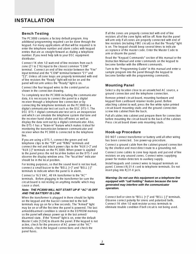
Bench TestingThe PC3000 contains a factory default program. Anyadditional programming required can be done through thekeypad. For many applications all that will be required is toenter the telephone number and alarm codes with keypadentries that are as straight forward as dialing a telephonenumber. If you need help talk to your DSC equipmentdistributor.Connect 1K ohm 1/2 watt end of line resistors from eachzone (Z1 to Z16) input to the closest common “COM”terminal. Connect an end of line resistor between the “Fire”input terminal and the “COM” terminal between “Z1” and“Z2”. Unless all zone loops are properly terminated with endof line resistors the “Ready” light will not be on and thepanel will not arm unless the “Ready” light is on.
Connect the four keypad wires to the control panel asshown in the connection drawing.
To completely test the PC3000 including the communicatordata, it is necessary to connect the panel to a digitalreceiver through a telephone line connection or byconnecting the telephone terminals on the PC3000 to adigital communicator test set such as the DSC DTS-1. TheDSC DTS-1 digital communicator test set is an inexpensiveunit which can simulate the telephone system dial tone andthe receiver hand shake and kiss-off tones as well asdisplay the data sent out by a digital communicator. Also,the DTS-1 has a “listen-in” feature which makes it ideal formonitoring the transmission between communicator andreceiver when the PC3000 is connected to the telephoneline.
If you are using a DTS-1, connect the green and redtelephone clips to the “TIP” and “RING” terminals andconnect the red and black power clips to the “AUX [+]” and“AUX [-]” terminals on the PC3000. When power is appliedto the panel press the red local-line button on the DTS-1 andobserve the display window area. The “local-line” indicatorshould be in the local position.For testing purposes, so that the sound level is not too loud,connect a small buzzer to the “BELL [+]” and “BELL [-]”terminals to indicate when the panel is in alarm.
Connect a 16.5 VAC, 40 VA transformer to the “AC”terminals. Before plugging in the transformer be sure thecircuit board is not resting on anything metallic which maycause a short.
Note: THE PC3000 WILL NOT START UP IF “AC” IS OFFAND THE BATTERY IS LOW.When the transformer is plugged in there should be lightson the keypad and the buzzer connected to the bellterminals may go on for a few seconds. The “Armed” lightmay be on or off the first time the panel is powered. The lastarmed/disarmed condition is stored in the EEPROM memoryso the panel will always power up in the last armed/disarmed state. If the “Armed” light is on, enter the defaultMaster Code [1234] to disarm the panel. If the keypad is notactive, check for the presence of AC power at the “AC”terminals, check the keypad connections and check thepanel fuses.
If all the zones are properly connected with end of lineresistors all of the zone lights will be off. Note that the panelwill arm only if all zones are properly connected with end ofline resistors (including FIRE circuit) so that the “Ready” lightis on. The keypad should beep several times to indicateacceptance of the master code. Enter the Master Code toarm or disarm the panel.
Read the “Keypad Commands” section of this manual or theInstruction Manual and enter commands on the keypad tobecome familiar with the different commands.
Turn to the “Programming Guide” in this manual and enter asample program into the panel through the keypad tobecome familiar with the programming commands.
Mounting PanelSelect a dry location close to an unswitched AC source, aground connection and the telephone connection.
Remove printed circuit board, mounting hardware andkeypad from cardboard retainer inside panel. Beforeattaching cabinet to wall, press the five white nylon printedcircuit board mounting studs and the ground connectionscrew into cabinet from the back.
Pull all cables into cabinet and prepare them for connectionbefore mounting the circuit board to the back of the cabinet.Press circuit board down onto mounting studs.
Hook-up ProcedureDO NOT connect transformer or battery until all other wiringhas been connected. See power-up procedure.
Connect a ground cable from the cabinet ground connectionby the shortest and most direct route to a grounding rod.
Connect zone cables to zone loop inputs and put end of lineresistors on any unused zones. Connect wires supplyingpower for motion detectors to auxiliary supply.
Install keypads and connect wires to keypad terminals onpanel. Connect RJ31-X cord to telephone terminals. Do notinsert plug into RJ31-X jack.
Warning: Do not use this equipment on a telephone lineequipped with “call holding” feature because the tonegenerated may interfere with the communicatoroperation.
Connect bell or siren to “BELL [+]” and “BELL [-]” terminals.Observe correct polarity for sirens and polarized bells.Connect 1K ohm 1/2 watt resistor across terminals toeliminate trouble condition if bell circuit is not being used.

4
Terminal Connections“AC” Power TerminalsUse a 16.5 VAC transformer with a minimum 40 VA rating tosupply AC power to the PC3000. The transformer should notbe connected to an outlet that is controlled by a switch. If ACfailure occurs it is displayed as a trouble on the keypad (see“Keypad Functions [Q][2] Trouble Conditions”). It can also betransmitted to the monitoring station as a trouble condition(see “Programming Guide [Q][8]” sections [09] and [10] foralarm and restore codes and section [20] for ACtransmission delay).
Auxiliary Power Terminals “AUX” and “GND”The auxiliary power supply can be used to power motiondetectors and other devices requiring 12 VDC. 400 mA 12VDC is available from the “AUX” (positive) and “GND”(negative) terminals when the PC3000 is used with onekeypad. For each additional keypad the auxiliary supplyrating must be reduced by 60 mA. The auxiliary supply isfused with the keypad supply at 1 amp. Auxiliary fuse failuretransmission can be sent (see [Q][8] sections [09] and [10]).
Switched Auxiliary Power Terminals“SW AUX” and “GND”The switched auxiliary supply can be switched offmomentarily from the keypad (see “Keypad Commands[Q][4]”). The “SW AUX” terminal is positive and the “GND”terminal negative. The 400 mA auxiliary supply rating must bereduced by any current taken from the switched auxiliarysupply. The switched supply shares the same fuse as theauxiliary supply.
Bell/Siren Terminals “BELL [+]” and “BELL [-]”
These terminals are for powering bells or other devicesrequiring a steady output voltage on alarm. The bell output isfused for 5 amps. When connecting sirens (speakers withsiren driver already built-in), be sure to observe the correctpolarity. Connect the positive lead to the “BELL [+]” terminaland the negative lead to the “BELL [-]” terminal.
If no siren or bell is used, connect a 1000 ohm resistorbetween “BELL [+]” to “BELL [-]”. The bell/siren alarm outputis pulsed (1 second on 1 second off) when an alarm iscreated by the [F] keypad zone, by the FIRE zone, or whenthe Bell Pulse option is enabled in section [19] light 1.
Keypad Terminals “RED”, “BLK”, “YEL” and “GRN”Connect the four coloured wires from the keypads to theseterminals. When connecting more than one keypad, connectin parallel across the keypad terminals at the control panel(i.e. all reds wires together, all blacks together, all yellowstogether and all greens together). The keypad red and blackpower supply terminals are fused through the auxiliary fuse.
Programmable Output Terminal “PGM OUT”The operation of the Programmable Output depends uponwhich option is selected in the programming table. See the“Programming Guide” section [28] for a list of options for the“PGM OUT” output. The “PGM OUT” is a 50 mA maximum
switch to ground. A 100 ohm current limiting resistor isconnected in series. A small relay, a buzzer or other DCoperated device may be connected between the 12 VDC
“AUX” (positive) terminal and the “PGM OUT” (switchednegative) terminal on the main board.
Auxiliary Input Terminal “AUX IN” (also KEY ARMING)The “AUX IN” input terminal is a normally open 24 hour zone.It can be programmed from the keypad to be silent oraudible. There is no display on the keypad for the “AUX IN”input. An alarm on this input is created by applying a positivevoltage or by closing a contact between the “AUX IN”terminal and the positive auxiliary supply. See “ProgrammingGuide [Q] [8]” sections [09] and [10] for programming thealarm and restoral codes.The “AUX IN” terminal can also be used as a momentary keyarming/disarming input. See “Programming Guide” section[28] for a list of options for the “AUX IN” terminal.
“FIRE” Zone InputThe “FIRE” zone is a supervised (normally open alarminitiating contact) end-of-line resistor circuit designed toaccept “Latching” four-wire smoke detectors.(See “Fire Circuit Installation Diagram”.)On alarm, (fire loop shorted) the bell output will pulse thesignal to indicate that the fire loop has been activated. Alarmmemory and transmission by the digital communicator isdelayed 30 seconds. If the alarm is acknowledged, bypressing the [#] key before the 30 second delay has expiredthe signals will silence and the transmission will be delayed.If the alarm is not acknowledged and the 30 second delayexpires, the fire memory latches and the transmission cannotbe cancelled.
If the smoke detector is not restored to normal after thesignal has silenced, the signal will resound after 90 seconds.And 30 seconds after that, the communicator will transmit. Ifthe signals resound, they may again be silenced, [#] key,and the communicator will be delayed if silence occurswithin the 30 second delay period.To restore the smoke detector to normal, clear all productsof combustion from the detector and reset the detector bypressing [Q] and then holding down [4] for 2 or 3 seconds.This action will remove power from the smoke detector and ifit is clear of smoke, the detector will return to normal. If thedetector is still in alarm, the signals will sound immediatelyand the above sequence will repeat.
For an open on the FIRE loop, the keypad sounder will beeptwice every 10 seconds and the “Trouble” light will show onthe keypad. The communicator will transmit the troublecondition if programmed for trouble transmission. Theaudible “Trouble” signal may be silenced by pressing the [#]key. To determine the nature of the trouble, press [Q][2]. (seethe “Trouble Display” section.)
5
Zone Input Terminals “Z1” to “Z16”
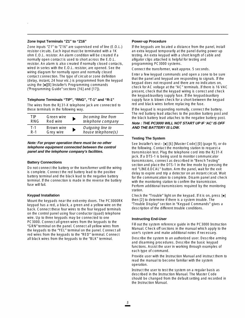
Zone inputs “Z1” to “Z16” are supervised end of line (E.O.L.)resistor circuits. Each input must be terminated with a 1Kohm E.O.L. resistor. An alarm condition will be created if anormally open contact is used to short across the E.O.L.resistor. An alarm is also created if normally closed contacts,wired in series with the E.O.L. resistor, are opened. See thewiring diagram for normally open and normally closedcontact connection. The type of circuit or zone definition(delay, instant, 24 hour etc.) is programmed from the keypadusing the [Q][8] Installer’s Programming commands("Programming Guide" sections [16] and [17]).
Telephone Terminals “TIP”, “RNG”, “T-1” and “R-1”
The wires from the RJ31-X telephone jack are connected tothese terminals in the following way.
TIP Green wire Incoming line fromRNG Red wire telephone company
T-1 Brown wire Outgoing line toR-1 Grey wire house telephone(s)
Note: For proper operation there must be no othertelephone equipment connected between the controlpanel and the telephone company's facilities.
Battery Connections
Do not connect the battery or the transformer until the wiringis complete. Connect the red battery lead to the positivebattery terminal and the black lead to the negative batteryterminal. If the connection is made in the reverse the batteryfuse will fail.
Keypad Installation
Mount the keypads near the exit-entry doors. The PC3000RKkeypad has a red, a black, a green and a yellow wire on theback. Connect these four wires to the four keypad terminalson the control panel using four conductor (quad) telephonewire. Up to three keypads may be connected to onePC3000. Connect all green wires from the keypads to the“GRN” terminal on the panel. Connect all yellow wires fromthe keypads to the “YEL” terminal on the panel. Connect allred wires from the keypads to the “RED” terminal. Connectall black wires from the keypads to the “BLK” terminal.
Power-up Procedure
If the keypads are located a distance from the panel, installan extra keypad temporarily at the panel during power uptesting. An extra keypad with a short length of cable andalligator clips attached is helpful for testing andprogramming PC3000 systems.
Connect the transformer, wait approx. 5 seconds.Enter a few keypad commands and open a zone to be surethat the panel and keypad are responding to signals. If thekeypad does not respond and there are no indicators on,check for AC voltage at the “AC” terminals. If there is 16 VACpresent, check that the keypad wiring is correct and checkthe keypad/auxiliary supply fuse. If the keypad/auxiliarysupply fuse is blown check for a short between the keypadred and black wires before replacing the fuse.
If the keypad is responding normally, connect the battery.The red battery lead attaches to the positive battery post andthe black battery lead attaches to the negative battery post.
Note : THE PC3000 WILL NOT START UP IF ‘AC’ IS OFFAND THE BATTERY IS LOW.
Testing The System
See Installer’s test - [Q] [6] [Master Code] [0] (page 9), or dothe following. Contact the monitoring station to request atransmission test. Plug the telephone cord into the RJ31-Xjack. If a DTS-1 is being used to monitor communicatortransmissions, connect as described in “Bench Testing”section and place the DTS-1 in the line mode by pressing thered “LINE/LOCAL” button. Arm the panel, wait for the exitdelay to expire and trip a detector on an instant circuit. Waitfor the communication to complete. Disarm panel and checkwith the monitoring station to confirm the transmission.Perform additional transmissions required by the monitoringstation.
Check the “Trouble” light on the keypad. If it is on, press [Q]then [2] to determine if there is a system trouble. The“Trouble Display” section in “Keypad Commands” gives adescription of the different trouble conditions.
Instructing End-User
Fill out the system reference guide in the PC3000 InstructionManual. Check off sections in the manual which apply to theuser’s system and make additional notes if necessary.
Describe the system to an authorized user. Describe armingand disarming procedures. Describe the basic keypadfunctions. Assist the user in working through examples ofeach type of command.Provide user with the Instruction Manual and instruct them toread the manual to become familiar with the systemoperation.
Instruct the user to test the system on a regular basis asdescribed in the Instruction Manual. The Master Codeshould be changed from the default setting and recorded inthe Instruction Manual.
6
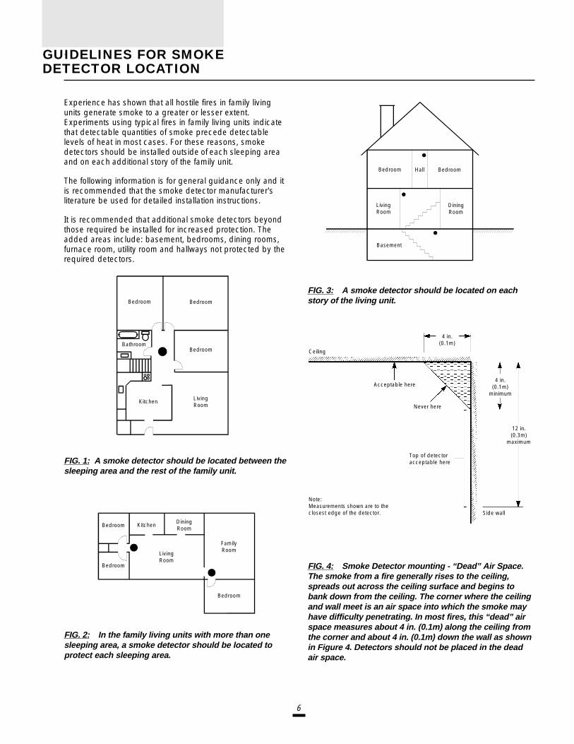
Experience has shown that all hostile fires in family livingunits generate smoke to a greater or lesser extent.Experiments using typical fires in family living units indicatethat detectable quantities of smoke precede detectablelevels of heat in most cases. For these reasons, smokedetectors should be installed outside of each sleeping areaand on each additional story of the family unit.
The following information is for general guidance only and itis recommended that the smoke detector manufacturer'sliterature be used for detailed installation instructions.
It is recommended that additional smoke detectors beyondthose required be installed for increased protection. Theadded areas include: basement, bedrooms, dining rooms,furnace room, utility room and hallways not protected by therequired detectors.
FIG. 1: A smoke detector should be located between thesleeping area and the rest of the family unit.
FIG. 2: In the family living units with more than onesleeping area, a smoke detector should be located toprotect each sleeping area.
FIG. 3: A smoke detector should be located on eachstory of the living unit.
FIG. 4: Smoke Detector mounting - “Dead” Air Space.The smoke from a fire generally rises to the ceiling,spreads out across the ceiling surface and begins tobank down from the ceiling. The corner where the ceilingand wall meet is an air space into which the smoke mayhave difficulty penetrating. In most fires, this “dead” airspace measures about 4 in. (0.1m) along the ceiling fromthe corner and about 4 in. (0.1m) down the wall as shownin Figure 4. Detectors should not be placed in the deadair space.
Bedroom Bedroom
DiningRoom
LivingRoom
Hall
Basement
Bedroom Bedroom
BedroomBathroom
Kitchen LivingRoom
Bedroom
LivingRoom
DiningRoom
KitchenBedroom
Bedroom
FamilyRoom
Acceptable here
Top of detectoracceptable here
Side wall
Note:Measurements shown are to theclosest edge of the detector.
4 in.(0.1m)
minimum
12 in.(0.3m)
maximum
Never here
Ceiling
4 in.(0.1m)
GUIDELINES FOR SMOKEDETECTOR LOCATION

7
KEYPAD FUNCTIONS
IntroductionThe PC3000RK remote keypad provides completeinformation and control of the PC3000 control panel. Thepanel can be fully programmed from the keypad. The 16zone lights and the fire alarm light provide alarm and statusindication for the alarm circuits. The 6 function lights guidethe user in operating the system. The built-in buzzer lets theuser hear correct key entries and other alert signals. The 12-key keypad is used for code entry and other programmingfunctions. All keypad entries are made by pressing one keyat a time.The keypad is normally resting in the arm-disarm mode. Inthis condition the zone lights are indicating the opening andclosing of zones. The “Ready” light comes on when all zonesare closed. The system can be directed to perform otherfunctions such as zone bypassing, displaying troubleconditions, displaying alarm memory and programming byentering one of the various [Q] commands described below.Pressing the [#] key or not making any key entry for 2minutes always returns the keypad to the arm-disarm mode.
Master CodeA default Master Security Code “1234” is programmed intothe PC3000 at the factory. The Master Security Code is usedfor arming and disarming the control panel, for programmingup to fifteen additional security codes using the [Q][5]command and for entering other user functions using the[Q][6] command. The Master Code can be reprogrammed ifthe installer leaves section [19] light 2 off. Because thePC3000 uses EEPROM memory the codes and other dataare retained even after complete AC and battery failure.
Installer’s Programming CodeA default Installer’s Programming Code “3000” isprogrammed into the PC3000. This code is used with the[Q][8] command by the installer to gain access to the systemin order to enter panel or communicator program information.The Installer’s Programming Code may be changed by theinstaller.
ArmingCheck to see if the “Trouble” or “Bypass” light is on beforearming the PC3000. Close all protected doors and windowsand stop movement in areas covered by motion detectors.Check to see that the “Ready” light is on (all zones areclosed). The system cannot be armed unless the “Ready”light is on. Enter a [4 Digit Security Code]. As each digit isentered the keypad buzzer will beep. If the security codewas entered incorrectly, the sounder will beep steadily for 2seconds. If the code was entered correctly but the “Ready”light was not on, the keypad will beep quickly followed by asteady tone. When the correct code is entered, the “Armed”light will come on and the keypad buzzer will beep quickly.Exit the premises through the designated exit-entry door. Atthe end of the allowed exit time all lights on the keypad willgo out except the “Armed” light. See the “Installer’sProgramming [Q][8] Command” section [22] for instructionson how to change the exit time. Also see, “Quick Arm” and“At Home Arming”.
DisarmingEnter the premises through the designated exit-entry door.The keypad buzzer will be on. Go to the keypad and enterthe [4 digit security code]. If an error is made in entering thecode, press the [#] key and enter the code again. The“Armed” light will go out and the keypad sounder will stop.The correct security code must be entered before theallowed entry time expires. To change the entry time see“Installer’s Programming Command”, [Q][8]. If an alarmoccurred while the panel was armed, the “Memory” light andthe “Zone” light which caused the alarm will start to flash andstay flashing for 2 minutes when the panel is disarmed.Pressing the [#] key returns the panel to the normal arm-disarm mode.
Auto-bypass/Home-Away ArmingIf a correct security code is entered, and you do not exit thepremises, the system will, at the end of the Exit delay time,arm with interior zones automatically bypassed if thoseinterior zones have been programmed as “Home-Away”zones. The “Bypass” light will come on immediately followingthe arming code being entered until a delay zone is trippedor [Q] [1] is entered to reactivate bypassed home-awayzones. (See programming sections [16] and [17], zonedefinitions for programming zones as “Home-Away”.)This is a convenience feature for the user who wishes toremain at home with the system armed. The user does nothave to manually bypass the home-away zones.To reactivate the home-away zones that have beenautomatically bypassed, press [Q] [1]. The “Bypass” light willgo out. This command is a quick method of fully arming thesystem before going to bed.
Zone BypassingA bypassed zone will not cause an alarm. If a zone isbypassed the panel may be armed (“Ready” light will be on)even if the zone is open. Use zone bypassing when accessis needed to part of the protected area. Also, damagedwiring or contacts on a zone may be temporarily bypasseduntil repairs can be made so that the panel can be armed.
[Q]+[1]To bypass zones, enter [Q] [1] and the zone number(s) to bebypassed. Press [#] to return to “Ready” (arm-disarmmode). When bypassing zones, two digits must be enteredfor the zone number(s) to be bypassed (e.g. [Q] [1][01]....[16]). To remove all bypasses, enter [Q] [1] [00] [#].The “Zone” lights which are on, while the “Bypass” light isflashing, indicate the bypassed zones. Remember that if nokeypad entry is made for more than 2 minutes the keypadwill return to the arm-disarm mode. Then, in order to bypassa zone the complete command must be re-entered. Oncethe bypass command is entered, pressing [99] recalls thelast zone or group of zones which was bypassed. If thesame group of zones is bypassed each time, this bypassrecall feature can be used instead of having to bypass zonesindividually.When the PC3000 is programmed, the ability to bypasscertain zones may be eliminated. In this case, the “Zone”lights for those zones will not come on in response to the

8
bypass command. See the “Zone Bypass Mask” instructionin the [Q][8] Installer’s programming section. If the “Bypass”light is on when arming the panel, the [Q][1] commandshould be used to see which zones are bypassed so thatzones are not unintentionally bypassed. Zone bypasses areautomatically cancelled when the panel is disarmed.
[Q] + [1] + [Access Code]If light 8 in section [19] is on then a code must be enteredwith [Q]+[1] to bypass zones. Only the zones assigned to thesame side of the system as the user code can be bypassed.The ability to bypass using certain access codes can beeliminated. See the “Access Bypass Mask” instruction in the[Q] [8] Installer’s Programming section.
Note: At no time can any armed zone be bypassed.
Trouble Display[Q]+[2]The PC3000 continuously monitors a number of possibletrouble conditions. If one of these conditions occurs, thekeypad “Trouble” indicator will light and the audibleindication will sound (two short beeps every 10 seconds).When the [#] key is pressed the audible indication will stopbut the “Trouble” indicator light will remain on until thetrouble is cleared. Trouble conditions can also betransmitted to the monitoring station (see “ProgrammingGuide” sections [09] and [10] for alarm and restoral troublecodes). Press the [Q] then [2] keys to display the type oftrouble. The “Zone” lights indicate the type of troublecondition.1 Low stand-by battery2 AC power failure3 Day zone trouble4 Telephone line trouble5 Fail to communicate6 Bell circuit failure7 Fire alarm circuit trouble8 Loss of time on internal clockPress [#] to return to “Ready”.
1 Low Battery... A battery trouble will be displayed and canbe reported if the battery is weak, disconnected or thebattery fuse is blown. Only one low battery alarm or restoraltransmission takes place per arming period. Low batterytrouble display is latching and can only be cleared bybattery restoration, arming and disarming panel.
2 AC Power Failure... There is no audible annunciation onAC power failure. The system “Trouble” light will come on butthe audible indication will not sound until there is a lowbattery condition. Transmission delay can be programmedfor 1 to 99 minutes. See “Programming Guide” section [22].
3 Day Zone Trouble... This trouble applies only to zoneswhich have been programmed as day zones. (“ProgrammingGuide” sections 16 and 17). A day zone creates a troublesignal when the panel is disarmed and an alarm signal whenthe panel is armed.
44444 Telephone Line Trouble...Telephone Line Trouble...Telephone Line Trouble...Telephone Line Trouble...Telephone Line Trouble... A telephone line trouble isgenerated when the line voltage drops below 3 volts for morethan 60 seconds. It generates a keypad trouble when thesystem is disarmed and rings a local alarm when the panel isarmed if section [19] light 5 is off.
55555 Fail to Communicate...Fail to Communicate...Fail to Communicate...Fail to Communicate...Fail to Communicate... If the digital communicator isunsuccessful communicating with the monitoring station aftereight attempts, a trouble is generated.If a later attempt to communicate is successful the trouble iscleared. Also the trouble will be cleared when the troubledisplay is viewed and exited.
66666 Bell Circuit Failure...Bell Circuit Failure...Bell Circuit Failure...Bell Circuit Failure...Bell Circuit Failure... If the bell fuse fails or the bell circuitis open, a keypad trouble and a trouble transmission aregenerated.
77777 Fire Alarm Circuit Trouble...Fire Alarm Circuit Trouble...Fire Alarm Circuit Trouble...Fire Alarm Circuit Trouble...Fire Alarm Circuit Trouble... If a Fire zone is open circuit,a keypad trouble and a trouble transmission are generated.A trouble on the Fire zone will unconditionally initiate anaudible indication on the keypad. This means that even ifany other previous trouble has been silenced, a Fire zonetrouble will restart the keypad buzzer.
88888 Loss of Internal Time...Loss of Internal Time...Loss of Internal Time...Loss of Internal Time...Loss of Internal Time... When the PC3000 is powered upor reset, the internal time of day clock needs to be set to thecorrect time. This trouble is cleared when the trouble displayis viewed and exited or when an attempt is made to reset theinternal time of day clock. See “[Q][6] User’s FunctionCommand” for resetting time of day clock.If the [9] is pressed while in the trouble display mode themost recent trouble will be displayed on the zone LEDs. Thistrouble memory feature is useful as a diagnostic aid wheninstalling and servicing the PC3000.
Alarm Memory Display[Q]+[3]Press [Q] then [3] to enter the alarm memory mode. The“Memory” light will flash and any alarm caused during thelast armed period will be displayed on the zone lights. Inaddition to the last alarm memory there are 2 history levels.After entering the memory mode (pressing [Q] then [3]),pressing [9] will cause the keypad to display the two otherlevels of alarm history. Each time [9] is pressed the keypadwill beep 1, 2 or 3 times to indicate which level of history isbeing viewed. When the panel is armed, the last alarmmemory is cleared and the contents moves to the 1st historylevel. The “Memory” light will only be on when there was analarm during the last armed period.Press [#] to return to “Ready”.
Switched Auxiliary Supply Control[Q]+[Hold Down 4]To interrupt the switched auxiliary power supply press [Q]then hold down [4] for the desired interrupt time. When the[4] is released the system returns to the “Ready” mode andthe switched auxiliary supply is restored.

9
User’s Programming Commands[Q]+[5]+[MASTER CODE]The [Q][5] user’s programming command is used to programadditional access codes. Up to 16 user arm-disarm codesmay be programmed. The 1st code is the Master Code(factory default [1234]). The 16th code is optionally a “OneTime Use” or maid code. The 16th code may be changedfrom a “One Time Use” code to a regular code using aninstaller’s programming command (section [18]...1st systemoption code). Remember if no keypad entry is made for morethan 2 minutes the keypad will return to the normal arm-disarm display and the complete command will have to bere-entered to program a new access code.
Programming Additional Access Codes
11111 Press the [Q] and [5] keys then enter the Master SecurityCode (default [1234]) to enter the additional codeprogramming mode. The “Program” light and “Zone 1” lightwill be on to show that the first code (the Master Code) isalready programmed with the factory default code [1234].The Master Code may be changed but do not try to erasethe Master Code. The installer can disable user changing ofthe Master Code by turning on light 2 in section [19].
22222 15 additional codes may be programmed. The zone lightsare used to indicate which of these codes are alreadyprogrammed (zone light on steady) and the one which iscurrently being programmed (zone light is flashing).
33333 To program the second code, press [02] then enter a 4digit code. Zone 2 light will flash and sounder will beep threetimes and zone light 2 will come on steady after the 4 digitcode is entered.
44444 To remove the second code, press [02] - the buzzer willbeep three times and zone light 2 will flash. Enter [Q] [Q] [Q] [Q],the buzzer will beep three times and zone 2 light will go outto show that the code has been removed.
55555 Follow the instructions in 33333 or 44444 for programming orremoving any of the other additional codes.
66666 Do not try to remove the Master Code (1st code). TheMaster Code may be changed but it must not be removed.When changing the Master Code be sure to enter a valid 4digit number (use only number keys 0 to 9). Do not enter [#]or [Q] as one of the digits. If the Master Code is forgotten andthe panel is left disarmed, program a new Master Codeusing the [Q][8][Installer’s Code][25] command. If the MasterCode is forgotten and the panel is left armed, the entireprogramming can be reset to factory default by using the“Hardware Reset” method described on page 21.
77777 To successfully program or remove additional codes, thepanel must be put into the code program mode by followingstep 1 followed by steps 3 or 4. Note that if no key entry ismade for 2 minutes the panel will go back to the normalarm/disarm mode, after which step 1 must be repeated toget back into the code program mode.
88888 To exit the code program mode press [#].
To review:
programming a new code;enter [Q] [5] [Master Code] [01 to 16] [4 digit code]eliminating an existing code;
enter [Q] [5] [Master Code] [02 to 16] [Q Q Q Q].Note: The access code, numbers must be entered as twodigits. E.g. 02, 03,......, 15, 16.
User’s Functions Command[Q]+[6]+[MASTER CODE]This command is used to set the system clock time and toset the Auto-arm time. It is also used to turn on and off anumber of system functions. The command is used byentering [Q], [6], [Master Code] then a number from thefollowing list to select the item to be changed.
[0] Installer’s test
[1] System 24 hour clock (enter HH:MM)[2] Auto-arming time (enter HH:MM)
[3] DO NOT USE
[4] Quick arm enable/disable[5] Auto-arm enable/disable
[6] Door chime enable/disable
[7] DO NOT USE[8] Bell test function
[9] User Initiated Callup
Note: The system clock is a 24 hour clock and timesmust be entered as two digit number.e.g. HH - 00, 01,.....10, 11,.....22, 23
MM - 00, 01,.....35, 36.....58, 59Items 1 and 2 are time setting functions. Enter 4 digitsrepresenting the time in hours and minutes (HH:MM) basedon the 24 hour or military clock. Always enter a leading zerowhere only one digit is required, 8:05 am would be enteredas 0805, 1:30 pm would be entered as 1330. Items [0], [4],[5] and [6] turn on and off various features. When the itemkey is pressed, the feature is turned on if the keypad beepsquickly 3 times. The feature is turned off if the keypadsounds one long beep. Pressing item [8] gives a 2 secondbell and keypad light test. Pressing [9] makes the panel callthe Downloading computer if enabled in section [47].

10
Installer’s Test[QQQQQ]+[6]+[MASTER CODE]+[0]This feature is designed to assist the installer in testing thesystem. In this mode, the bell or siren will operate for twoseconds each time a device is tripped and the zone alarmwill be put into the first level memory. The feature isautomatically disabled when the panel is armed anddisarmed. Each time a zone is tripped or restored in thismode, a signal, if programmed, will be transmitted to themonitoring station. If this is not desired, it is possible todisable the communicator during the test (see section [18]“1st System Option Code”).
Notes: Do not use the PC16OUT module during theinstaller’s test.Do not use the installer’s test when the panel is partiallyarmed.
Setting the Clock[Q]+[6]+[MASTER CODE]+[1]Setting the “System 24 Hour Clock” (item [1]) tells the systemthe correct time of day. If the system is without battery andAC power it cannot continue to keep time. Therefore whenthe panel is first powered up or when it has been without ACpower long enough to completely discharge the stand-bybattery, the “System 24 Hour Clock” must be reset. If the timeneeds to be reset a “Trouble #8” will be indicated on thekeypad (see [Q][2] “System Trouble Command”).
Auto-arm Time of Day[Q]+[6]+[MASTER CODE]+[2]The PC3000 can be programmed to arm at the same timeeach day. Programming item [2] sets this time and thefeature must be enabled as shown in item [5] (see “Auto-armEnable” on this page).At the selected auto-arm time the keypad beeper begins tosound and the Bell/Siren will pulse once every 10 seconds toalert anyone on the premises that the system is about to arm.The Bell/Siren pulse can be silenced in section [51] byturning light 1 on.
The keypad beeper will sound for one minute before auto-arming unless one of the following two methods is used tocancel the auto-arm.
• Auto-arm Cancel : Any key can be pressed to cancel theauto-arm sequence and silence the keypad during the oneminute pre-alert (this is the default condition).
• Auto-arm Cancel with code : If section [51] light 2 is on,then a valid 4 digit access code is required to cancel theauto-arm sequence.
The auto-arm will be attempted at the same time thefollowing day. Any time an auto-arm is cancelled using oneof the above methods, the reporting code programmed insection [53] will be transmitted to the central station.
When the panel does arm by auto-arming, any open zoneswill be “Force-armed”. There is no exit delay following the 1minute auto-arm pre-warning. The panel is fully armed at themoment the 1 minute has expired.
Quick Arm[Q]+[6]+[MASTER CODE]+[4]The “Quick Arm” feature is enabled by pressing the [4] keywhile in the “User Functions Command” section. Whenenabled (enabled 3 beeps....disabled one long beep) thepanel can be armed by entering [Q][0]. The closing codetransmitted for “Quick Arm” is the same as the code which isprogrammed for the Master Code.
Auto-arm Enable[Q]+[6]+[MASTER CODE]+[5]Entering [Q] [6] [Master Code] [5] will enable/disable theAuto-arming feature. When the feature is being Enabled, thekeypad buzzer will sound 3 beeps and when being Disabledthe buzzer will sound one long beep.
Door Chime[Q]+[6]+[MASTER CODE]+[6]The “Door Chime” feature is enabled by pressing the [6] keywhile in the “User’s Functions Command” section. Whenenabled the keypad buzzer will beep quickly 5 times eachtime any zone defined as a delay or instant circuit opens orcloses. The “Door Chime” feature does not operate on otherzone definitions. Zone bypass may be used to eliminate“beeping” on doors where it is not wanted. This featureoperates only while the panel is disarmed.
System Test[Q]+[6]+[MASTER CODE]+[8]The system test feature sounds the bell or siren, lights thekeypad indicators and beeps the keypad buzzer for 2seconds. If a code is programmed in section [54] it will betransmitted at the same time.
User Callup[Q]+[6]+[MASTER CODE]+[9]This function is enabled in section [47]. When activated,the panel will call the downloading computer. Thedownloading computer must be waiting for the panel to callbefore downloading can be performed.

11
Utility Output Command[Q]+[7] OR [ Q]+[7]+[ACCESS CODE]The programmable output (PGM terminal) on the PC3000can be made to activate by a command from the keypad.This output can be used for operating other devices such as;garage door opener, special lighting or door strikes.The programmable output must be selected for keypad utilityusing the [Q][8][Installer’s Code][28] command andprogramming a [2], [3], [4] or [5].
Depending on the option chosen in the programmingsection, the programmable output is activated by pressingthe [Q] then [7] keys followed by a Group A access code.Group B access code, any access code, or no code at all.When the proper keys are pressed the keypad sounder andthe programmable output are activated for 5 seconds.
Installer’s Programming Commands[Q]+[8]+[INSTALLER’S CODE]The PC3000 is completely programmed from the keypad byusing commands in the [Q] [8] section. The commands aredescribed in detail in the programming section of thismanual.
“At Home” Arming[Q]+[9]+[ACCESS CODE]Entering [Q], [9] before the arming code, arms the panelwithout any entry delay on the delay zones and bypasseszones that are defined as “Home-Away”. This command isused for arming the system while at home. When the panel isarmed using [Q], [9], the “Armed” light will be on flashing andthe “Bypass” light will be on to indicate that the “Home-Away” zones are bypassed. Once the panel is armed in thismode, using [Q], [1] will remove the bypass from those zonesdefined as “Home-Away” if they have NOT been manuallybypassed. The [Q], [1] command used here, only removesthe bypass from zones that have been Automaticallybypassed with the [Q], [9] command.
“Quick Arm” Command[Q]+[0]Entering [Q][0] is accepted as a valid arming code whenthe “Quick Arm” feature is activated. Quick Arm may beused as a convenience for regular users or when thesytem is to be armed by individuals who are notauthorized to disarm the system. See instructions in the“[Q][6] User’s Functions Command” section for activatingthe “Quick Arm” feature. This feature should not beenabled if the One Time Use Code is enabled. The OneTime Use Code must be used for arming before it iserased.
Quick Exit[Q]+[0] When ArmedEntering [Q] [0] when the system is fully armed will allow theuser 2 minutes to exit the premises through any delay zonewithout altering the status of the system if the Quick Exitfeature is enabled. The Quick Exit feature can be enabled byturning on light 6 in section [51]. After [Q] [0] is entered intoan armed system, one and only one delay loop may betripped. Any additional activity on any other active loop willcause that loop to begin its alarm sequence.[Q] [0] for Quick Exit on a partially armed system is notsupported.
Quick Exit is not designed to extend the Standard ExistDelay.
Keypad ZonesThere are three zones which can be activated from thekeypad. The alarm and restoral codes for keypad zones areprogrammed using the [Q][8] command.
[F]ire Key
Pressing the [F] key for 2 seconds activates a Fire alarm. Thefire alarm sounds the siren/bell in a pulsed mode and isannunciated as a memory condition.
[A]uxiliary Key
Pressing the [A] key for 2 seconds activates an Auxiliarykeypad zone. If a reporting attempt is made to an alarmreceiver and it is successful the PC3000 will acknowledgethe transmission with a short series of beeps from thekeypad.
[P]anic Key
Pressing the [P] key for 2 seconds activates the Police (orPanic) alarm. The panic alarm can be programmed foraudible or silent operation (see section [18] in “ProgrammingGuide”).
There is no light annunciation from the keypad for the lasttwo keypad zones, however, the keypad buzzer beeps 3times to confirm activation on any of the keypad zones. If thekeys are held down the buzzer continues to beep. The panicalarm can be programmed for silent confirmation in section[51] light 4.See section [15] for alarm and restoral codes for all threekeypad zones.

12
DOWNLOADING
The PC3000 with version 7.0 or higher software, supports theDSC “downloading” package. See the downloading manualfor details on specific capabilities.
There are several sections pertaining to the downloadingfeature which must be programmed.
Section [23]
The time of day that the periodic download or testtransmission will be done, if selected, is programmed in thissection.
Section [26] - Downloading Access Code
A four digit code must be programmed into this section toallow access to the control panel by the downloadingcomputer.
Section [46] - Downloading Computer Telephone Number
If Callback is enabled, section [47] zone light [8], then thissection must be programmed with the telephone number ofthe downloading computer.
Section [47] - Modem Configuration
Zone lights [1] to [4] are programmed to set the number ofrings the panel will look for before it answers a call from thedownloading computer.
Zone light [5] is programmed to enable or disable thecontrol panel for downloading. If downloading is disabled, allother programming sections relating to downloading neednot be programmed.
Zone light [6] enables or disables user initiated callup to thedownloading computer.
Zone light [7] enables or disables the answering machinedefeat option (Answering Machine Over-ride).
Downloading and Answering Machine
The PC3000 software provides a means to handledownloading when an answering machine is also connectedto the telephone line. In section [47], if zone light 7 is off, it isassumed that there is no answering machine connected tothe telephone line and the panel will capture the line after theset number of rings.
If zone light 7 is off and an answering machine is connectedand it is set to answer before the panel, the panel will beunable to receive a call from a downloading computer. If thepanel is set to answer before the answering machine, theanswering machine will be unable to receive incomingmessages.
If zone light 7 is on and the panel is called for 1 or 2 ringsonly and then called again within a set time of 60 or 120seconds (set in section 51, light 7), the panel will thenanswer the second call on the first ring (Answering MachineOver-ride Timer).
Once the panel is connected to a downloading computer, no[Q] functions can be performed. If the [Q] key is pressedwhile the panel is connected to a downloading computer, thekeypad buzzer will sound one long tone to indicate an error.
Zone light [8]Zone light [8]Zone light [8]Zone light [8]Zone light [8] is programmed to enable or disablecallback. If callback is disabled, the downloadingcomputer will have immediate access to the control panel.The disabled mode is useful if there are multipledownloading computers (at different telephone numbers). Ifcallback is enabled the downloading computer will call,request access then hang up and wait for the control panelto call. After the control panel has called back and thedownloading computer and the control panel accept eachother as valid, downloading operations are enabled.
Section [48] - Panel Identification Code
A four digit code must be programmed into this section toallow the downloading computer to identify the panel it iscommunicating with.
Section [49] - 4th System Option Code
Zone light [8]Zone light [8]Zone light [8]Zone light [8]Zone light [8] is programmed to choose between periodicdownload (light ON) or test transmission (light OFF).
Section [51] - 3rd System Option Code
Zone light [7]Zone light [7]Zone light [7]Zone light [7]Zone light [7] sets the Answering Machine Over-ride Timerto either 60 or 120 seconds for defeating the answeringmachine.
See “Downloading and Answering Machine”.
13
IntroductionThe PC3000 is programmed by entering instructions from thepanel keypad. The PC3000 memory is EEPROM and can bereprogrammed thousands of times. The EEPROM will notlose memory even on total AC and battery failure. Allessential program information required to define theoperation of the control panel and the communicator isstored in a section of the EEPROM which can only beaccessed using the Installer’s Programming Code. If thecode is forgotten, the default program code can be re-inserted by using the “Hardware Reset” described on page22, unless Installer’s Lockout is enabled. See sections [90]and [91].
To begin programming the PC3000, enter [Q], [8], [3000]while the panel is disarmed. Installer’s Programming canonly be done while the panel is disarmed and not in alarm.The factory default Installer’s Programming Code is [3000].This default code can be changed using the Section [24]command listed below (new Installer’s Code). Once thebasic Installer’s command is entered ([Q] [8] [3000]) the“Program” light will start to flash. The “Program” light willcontinue to flash while programming. Note that whileprogramming, if no key entry is made for more than 2minutes, the keypad will return to the arm-disarm mode andthe complete installer’s command ([Q] [8] [3000]) must beentered before programming can resume.
The next step is to enter a 2 digit section entry for any of thecommands described in the following pages. Note that whilethe keypad is waiting for the section entry the “Armed” lightis on steady. As soon as the 2 digits are entered for thesection the keypad will beep 3 times, the “Armed” light willgo out and the “Ready” light will go on. The keypad is thenready to accept data entry for the selected section.A complete description of each programming section will begiven in the remaining pages of this section. A programmingwork sheet summarizing all programming commands isprovided in the next section of the manual. Fill out the worksheet and use it as a guide when programming.
As the required data for a programming section is entered,the hexadecimal value of the information in that location isdisplayed on zone lights 1-15. Most sections contain severalgroups of two digit entries. The keypad beeps twice and the“Armed” light flashes after each group of two digits isentered. When the required data is completely entered forthe section being programmed, the keypad will beep 5 timesand the “Armed” light will come back on to indicate that theexpected data has been entered and another section can beselected for programming. After completing one section, it isnot necessary to re-enter the [Q] [8] [Installers’ code] portionof the command. Just enter the number of anotherprogramming section. When programming a section, it ispossible to exit by pressing [#]. Only the data entered beforepressing [#] will be changed in the EEPROM. Practiceentering data in several sections until you become familiarwith the programming commands.
Certain programming entries may require “HEX” data. That isthe numbers 0 through 9 and the letters A through F (in“HEX” numbering the letters A...F represent the numbers10...15). Where commands require “HEX” data A-F, firstpress [Q]. The keys 1-6 now assume the hex values A-F andthe “Ready” light begins to flash. Key 1 = A, Key 2 = B, Key3 = C, Key4 = D, Key 5 = E and Key 6 = F. Pressing the [Q] again stopsthe “Ready” light from flashing and the keys assume thenormal values for the numbers from 1 to 9. The mostcommon mistake in entering “HEX” data is forgetting to press[Q] again after entering the “HEX” digit to return to normalnumber entry.The data for sections 18, 19, 20, 21, 29, 30, 31, 32, 43, 44,47, 49 and 51 is entered using the keypad zone lights toindicate which functions are active and the number keys toturn functions on and off. When the section number isentered, the zone lights 1...8 will display which functions arecurrently on. Pressing the number key corresponding to thezone light alternately turns the function on and off. Allfunctions can be turned off by entering [0]. When the correctselections have been made press [#] to record them inmemory and to go on to program the next section.
Reviewing Programmed DataEnter the section you wish to review by entering the 2 digitsection number. The zone LED’s will represent the value(hexadecimal format) of the first digit in that section. Eachpress of the ‘F’ key will advance the display to the next digit.At the end of the section, the keypad buzzer will beepseveral times and return you to the program mode whereanother section can be selected for review or programming.Note: Only sections [01] through [17], [22] through [28],[33], [45], [46], [48], [50] and [52] through [54] can bereviewed using the above method.
[00] Binary ProgrammingThis section is normally used upon instruction from factorytechnical personnel for specialized programming notcovered by the standard programming instructions.
PROGRAMMINGGUIDE

14
[01] 1st Phone NumberThis is the 1st telephone to which the communicator will dial.See section [33] “Communicator Call Direction Options”.After entering the section number [01], enter thecommunicator telephone number the way you would dial iton a telephone. Press [#] after the last digit to complete thetelephone number programming.
Enter [ Q 2 Q ] to dial a ‘Q’ (Hex B)Enter [ Q 3 Q ] for a 4 second pause (Hex C)Enter [ Q 4 Q ] for additional dial tone search (Hex D)Enter [ Q 5 Q ] to dial a ‘#’ (Hex E)
The total number of digits including dial tone searches andpauses must not exceed 16. Remember to press [#] afterentering the last digit of the phone number. Press [02] toprogram the next section, enter another section number orpress [#] a second time to return to the arm/disarm mode.
[02] 1st Account CodeThe 1st account code is always transmitted to the 1st phonenumber to identify the alarm customer. After entering theSection number [02], enter a 4 digit number. If “HEX” digits Ato F are required; enter [Q], [1]...[6] and [Q] again to returnkeys to normal decimal entry. Where a zero digit in theaccount code is required use “HEX A” ([Q][1][Q] to transmit10 pulses. The receiver at the monitoring station interprets10 pulses for a digit as a zero. If a three digit code isrequired as in 3/1 formats, enter [0] as the last digit. [0]represents a null digit....no pulses transmitted.
[03] 2nd Phone NumberThis is the second telephone number to which thecommunicator will dial. See section [01] “1st Phone Number”for programming instructions.
[04] 2nd Account CodeThe 2nd account code is always transmitted to the 2ndphone number. See section [02] “1st Account code” forprogramming instructions.
[05]...[15] Reporting Codes ExplanationSections [05] to [15] are used to program the communicatorreporting codes. A reporting code is transmitted along withthe account code with each transmission. If the reportingcodes are not programmed in these sections notransmission will be sent when an event (i.e. alarm, restoral,opening/closing, trouble etc.) takes place. To prevent atransmission from being sent for any event in the followingsections leave it unprogrammed or enter [00] as thereporting code.Eight reporting codes are programmed in each section.Once the section number is entered, the keypad expects 8two digit numbers to be entered for the 8 reporting codes inthat section. The keypad beeps twice and the “Armed” lightflashes after each 2 digit number is entered. After the 8thcode is entered, programming of the current section iscomplete. The keypad will beep 5 times, the “Ready” lightwill go off and the “Armed” light will go on. The keypad isthen ready to accept the next section number forprogramming.
When changing the reporting codes in a section, only codeentries up to the one which is being changed need to beentered. Press [#] to exit from the programming sequence.Only codes up to the last one entered will be changed.
[05] Alarm Reporting Codes Zones 1 to 8Once the Section code [05] is entered, the keypad expects 8two digit numbers to be entered as the reporting codes forzones 1 to 8 alarms (restorals in Section [07]). These codesare used by the communicator when there has been analarm on zones 1 to 8. Listed below are severalprogramming examples and the resulting transmission usingdifferent formats for the reporting codes. Obtaining differentformats requires entering data correctly in the account codesection ([02] or [04]) reporting codes sections ([05] to [15])and communication format options, section ([27]).
3/1 Format....Single Line or Non-extended Reporting
Required:
• 3 digit account code in sections [02] or [04]i.e. enter [1230] for account code 123
• Format code [0], [1], [2], [3], [4] depending on receivertype selected in section [27]
• Single digit alarm reporting code in section [05]i.e. enter [30] for single digit code 3 (0 is null digit i.e. nopulses transmitted)
Transmission sent:• 123 3
4/2 Format....Single Line Reporting
Required:
• 4 digit account code in Sections [02] or [04]i.e. enter [1234] for account code 1234
• Format code [0], [1], [2], [3], [4] depending on receivertype selected in section [27]
• Two digit alarm reporting code in section [05]i.e. enter [31] for two digit code 31
Transmission sent:• 1234 31
3/1 Format....Extended Reporting
Required:• 3 digit account code in Sections [02] or [04]
i.e. enter [1230] for account code 123
• Format code [8], [9], [A], [B], [C] depending on receivertype selected in section [27]
• Two digit alarm reporting code in section [05]i.e. enter [31]
Transmission sent:• 1st round 123 3• 2nd round 333 1
If a transmission is not wanted for a particular reportingcode, then enter 00 to disable that reporting code.

15
[06] Alarm Reporting CodesZones 9 to 16These reporting codes are used by the communicator totransmit a zone alarm for zones 9 to 16. Use instructions insection [05] as a guide for programming.
[07] Restoral Reporting CodesZones 1 to 8These reporting codes are used by the communicator totransmit a zone restoral for zones 1 to 8. Use instructions insection [05] as a guide for programming.
[08] Restoral Reporting CodesZones 9 to 16These reporting codes are used by the communicator totransmit a zone restoral for zones 9 to 16. Use instructions insection [05] as a guide for programming.
[09] Utility Alarm Reporting CodesThese reporting codes are used by the communicator totransmit the following conditions.• Fire Zone• Auxiliary Input Zone• Battery Trouble• AC Failure Trouble• Day Zone(s) Trouble• Bell Circuit Trouble• Fire Zone Trouble• Auxiliary Power Supply TroubleUse instructions in section [05] as a guide for programming.
See “Terminal Connections” section of manual for adescription of the operation of the Fire Zone and the AuxiliaryInput Zone. Section [28] contains options for Auxiliary InputZone. The Battery Trouble reporting code will be sent whenthe battery voltage drops below 11.5 volts. This reportingcode will also be sent because of a battery fuse failure. Thebattery is tested under load every 10 seconds. Only onetransmission will be sent during an arm or disarm period toprevent multiple transmission from a weak battery. The ACFailure Trouble reporting code will be sent after the delaytime programmed in section [22]. This preventstransmissions during temporary power failures. AuxiliaryPower Supply Trouble reporting code is sent when theauxiliary power supply fuse failed. The Bell Circuit Troublereporting code is sent when the bell circuit is open or thefuse failed. The Fire Zone Trouble code is sent when the firezone becomes open circuit (E.O.L. resistor is disconnected).The Day Zone Trouble code is sent when any zone definedas a Day Zone (see section [16], [17]) goes open when thesystem is disarmed. See [Q][2] “Trouble Command” sectionfor additional description of troubles.
[10] Utility Restoral Reporting CodesThese reporting codes are used by the communicator totransmit the following list of restoral conditions whichcorrespond to alarm conditions in section [09]. Useinstructions in section [05] as a guide for programming.• Fire Zone• Auxiliary Input Zone• Battery Trouble• AC Trouble• Day Zone(s) Trouble• Bell Circuit Trouble• Fire Zone Trouble• Auxiliary Power Supply Trouble
[11] Reporting Codes for Closing(Arming) via Access Codes 1 to 8The reporting codes in sections [11] to [14] are used toidentify “Openings and Closings” (disarming and arming ofthe system) by user access code.After entering the section code [11], enter 8 two digitreporting codes. The 8 reporting codes correspond to thefirst 8 access codes which are programmed using the [Q][5]command. When the system is armed using one of theaccess codes, the corresponding reporting code istransmitted.When transmitting in any of the extended formats, (seeexamples in section [05]), closing codes would beprogrammed as follows. [C1], [C2], [C3], [C4], [C5], [C6],[C7], [C8]........Where the first digit “HEX C” is one which is used torepresent a closing signal (this could be another numberdepending on what is used at the monitoring station) the 2nddigit represents the access code which was used to arm thesystem.The closing code transmission takes place after the exitdelay time. Therefore if the system is armed and disarmedbefore the expiry of the exit time, no transmission will takeplace.Remember that the 1st user code is the master code andthat the 16th code may be the temporary or maid’s code.The 16th user code can be converted to a normal codeusing one of the options in section [18].When the system has been armed using “Quick Arm” [Q][0]or “Auto-arm” (see [Q][6] “Keypad Commands”), the 1streporting code (reporting code for master code) will betransmitted. The master code is required to enable or disablethese functions.When the system is armed with one or more zones bypassed(see [Q][1] command for zone bypassing), the monitoringstation can be notified by programming the Partial Armreporting in section [15]. Note that the Partial Closing code issent in tandem with the regular closing code to identify it asa partial closing condition.
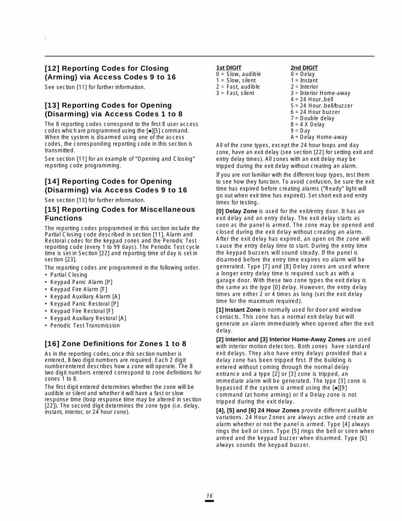
16
[12] Reporting Codes for Closing(Arming) via Access Codes 9 to 16See section [11] for further information.
[13] Reporting Codes for Opening(Disarming) via Access Codes 1 to 8The 8 reporting codes correspond to the first 8 user accesscodes which are programmed using the [Q][5] command.When the system is disarmed using one of the accesscodes, the corresponding reporting code in this section istransmitted.See section [11] for an example of “Opening and Closing”reporting code programming.
[14] Reporting Codes for Opening(Disarming) via Access Codes 9 to 16See section [13] for further information.
[15] Reporting Codes for MiscellaneousFunctionsThe reporting codes programmed in this section include thePartial Closing code described in section [11], Alarm andRestoral codes for the keypad zones and the Periodic Testreporting code (every 1 to 99 days). The Periodic Test cycletime is set in Section [22] and reporting time of day is set insection [23].The reporting codes are programmed in the following order.• Partial Closing• Keypad Panic Alarm [P]• Keypad Fire Alarm [F]• Keypad Auxiliary Alarm [A]• Keypad Panic Restoral [P]• Keypad Fire Restoral [F]• Keypad Auxiliary Restoral [A]• Periodic Test Transmission
[16] Zone Definitions for Zones 1 to 8As in the reporting codes, once this section number isentered, 8 two digit numbers are required. Each 2 digitnumber entered describes how a zone will operate. The 8two digit numbers entered correspond to zone definitions forzones 1 to 8.The first digit entered determines whether the zone will beaudible or silent and whether it will have a fast or slowresponse time (loop response time may be altered in section[22]). The second digit determines the zone type (i.e. delay,instant, interior, or 24 hour zone).
1st DIGIT 2nd DIGIT0 = Slow, audible 0 = Delay1 = Slow, silent 1 = Instant2 = Fast, audible 2 = Interior3 = Fast, silent 3 = Interior Home-away
4 = 24 Hour..bell5 = 24 Hour..bell/buzzer6 = 24 Hour buzzer7 = Double delay8 = 4 X Delay9 = DayA= Delay Home-away
All of the zone types, except the 24 hour loops and dayzone, have an exit delay (see section [22] for setting exit andentry delay times). All zones with an exit delay may betripped during the exit delay without creating an alarm.
If you are not familiar with the different loop types, test themto see how they function. To avoid confusion, be sure the exittime has expired before creating alarms (“Ready” light willgo out when exit time has expired). Set short exit and entrytimes for testing.[0] Delay Zone is used for the exit/entry door. It has anexit delay and an entry delay. The exit delay starts assoon as the panel is armed. The zone may be opened andclosed during the exit delay without creating an alarm.After the exit delay has expired, an open on the zone willcause the entry delay time to start. During the entry timethe keypad buzzers will sound steady. If the panel isdisarmed before the entry time expires no alarm will begenerated. Type [7] and [8] Delay zones are used wherea longer entry delay time is required such as with agarage door. With these two zone types the exit delay isthe same as the type [0] delay. However, the entry delaytimes are either 2 or 4 times as long (set the exit delaytime for the maximum required).[1] Instant Zone is normally used for door and windowcontacts. This zone has a normal exit delay but willgenerate an alarm immediately when opened after the exitdelay.
[2] Interior and [3] Interior Home-Away Zones are usedwith interior motion detectors. Both zones have standardexit delays. They also have entry delays provided that adelay zone has been tripped first. If the building isentered without coming through the normal delayentrance and a type [2] or [3] zone is tripped, animmediate alarm will be generated. The type [3] zone isbypassed if the system is armed using the [Q][9]command (at home arming) or if a Delay zone is nottripped during the exit delay.
[4], [5] and [6] 24 Hour Zones provide different audiblevariations. 24 Hour Zones are always active and create analarm whether or not the panel is armed. Type [4] alwaysrings the bell or siren. Type [5] rings the bell or siren whenarmed and the keypad buzzer when disarmed. Type [6]always sounds the keypad buzzer.
17
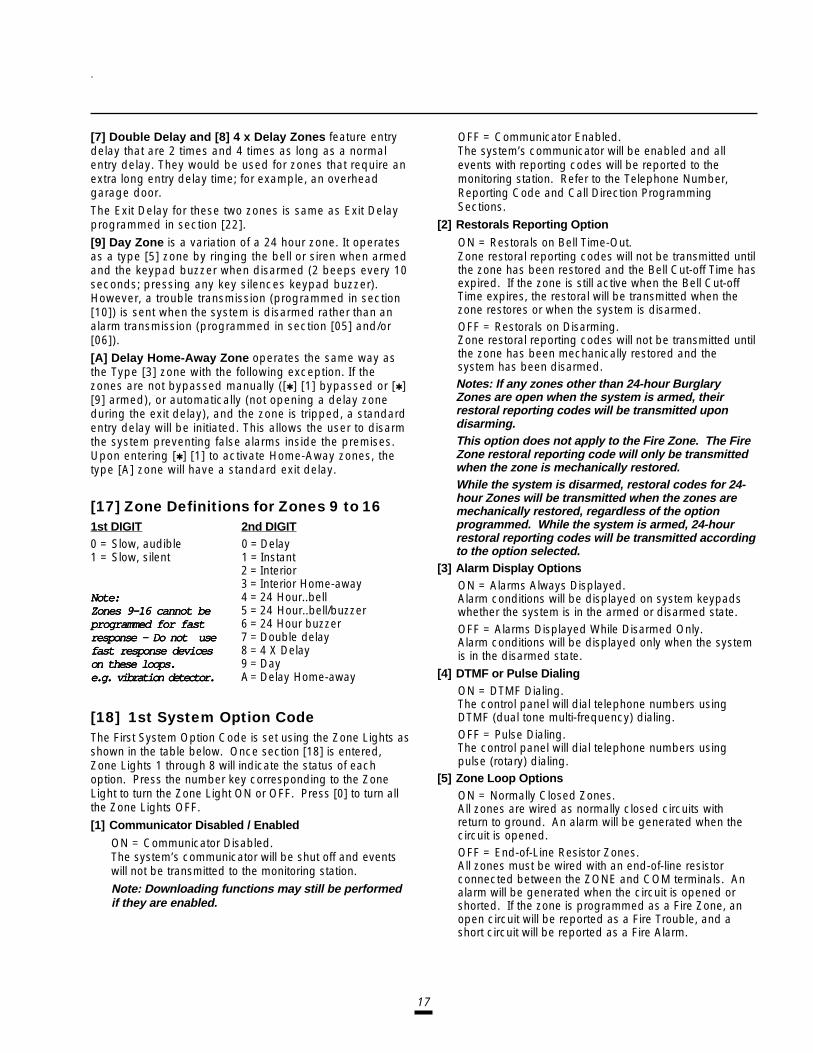
[7] Double Delay and [8] 4 x Delay Zones feature entrydelay that are 2 times and 4 times as long as a normalentry delay. They would be used for zones that require anextra long entry delay time; for example, an overheadgarage door.
The Exit Delay for these two zones is same as Exit Delayprogrammed in section [22].[9] Day Zone is a variation of a 24 hour zone. It operatesas a type [5] zone by ringing the bell or siren when armedand the keypad buzzer when disarmed (2 beeps every 10seconds; pressing any key silences keypad buzzer).However, a trouble transmission (programmed in section[10]) is sent when the system is disarmed rather than analarm transmission (programmed in section [05] and/or[06]).[A] Delay Home-Away Zone operates the same way asthe Type [3] zone with the following exception. If thezones are not bypassed manually ([Q] [1] bypassed or [Q][9] armed), or automatically (not opening a delay zoneduring the exit delay), and the zone is tripped, a standardentry delay will be initiated. This allows the user to disarmthe system preventing false alarms inside the premises.Upon entering [Q] [1] to activate Home-Away zones, thetype [A] zone will have a standard exit delay.
[17] Zone Definitions for Zones 9 to 161st DIGIT 2nd DIGIT0 = Slow, audible 0 = Delay1 = Slow, silent 1 = Instant
2 = Interior3 = Interior Home-away
Note:Note:Note:Note:Note: 4 = 24 Hour..bellZones 9-16 cannot beZones 9-16 cannot beZones 9-16 cannot beZones 9-16 cannot beZones 9-16 cannot be 5 = 24 Hour..bell/buzzerprogrammed for fastprogrammed for fastprogrammed for fastprogrammed for fastprogrammed for fast 6 = 24 Hour buzzerresponse - Do not useresponse - Do not useresponse - Do not useresponse - Do not useresponse - Do not use 7 = Double delayfast response devicesfast response devicesfast response devicesfast response devicesfast response devices 8 = 4 X Delayon these loops.on these loops.on these loops.on these loops.on these loops. 9 = Daye.g. vibration detector.e.g. vibration detector.e.g. vibration detector.e.g. vibration detector.e.g. vibration detector. A= Delay Home-away
[18] 1st System Option CodeThe First System Option Code is set using the Zone Lights asshown in the table below. Once section [18] is entered,Zone Lights 1 through 8 will indicate the status of eachoption. Press the number key corresponding to the ZoneLight to turn the Zone Light ON or OFF. Press [0] to turn allthe Zone Lights OFF.[1] Communicator Disabled / Enabled
ON = Communicator Disabled.The system’s communicator will be shut off and eventswill not be transmitted to the monitoring station.Note: Downloading functions may still be performedif they are enabled.
OFF = Communicator Enabled.The system’s communicator will be enabled and allevents with reporting codes will be reported to themonitoring station. Refer to the Telephone Number,Reporting Code and Call Direction ProgrammingSections.
[2] Restorals Reporting Option
ON = Restorals on Bell Time-Out.Zone restoral reporting codes will not be transmitted untilthe zone has been restored and the Bell Cut-off Time hasexpired. If the zone is still active when the Bell Cut-offTime expires, the restoral will be transmitted when thezone restores or when the system is disarmed.OFF = Restorals on Disarming.Zone restoral reporting codes will not be transmitted untilthe zone has been mechanically restored and thesystem has been disarmed.Notes: If any zones other than 24-hour BurglaryZones are open when the system is armed, theirrestoral reporting codes will be transmitted upondisarming.This option does not apply to the Fire Zone. The FireZone restoral reporting code will only be transmittedwhen the zone is mechanically restored.While the system is disarmed, restoral codes for 24-hour Zones will be transmitted when the zones aremechanically restored, regardless of the optionprogrammed. While the system is armed, 24-hourrestoral reporting codes will be transmitted accordingto the option selected.
[3] Alarm Display OptionsON = Alarms Always Displayed.Alarm conditions will be displayed on system keypadswhether the system is in the armed or disarmed state.OFF = Alarms Displayed While Disarmed Only.Alarm conditions will be displayed only when the systemis in the disarmed state.
[4] DTMF or Pulse DialingON = DTMF Dialing.The control panel will dial telephone numbers usingDTMF (dual tone multi-frequency) dialing.OFF = Pulse Dialing.The control panel will dial telephone numbers usingpulse (rotary) dialing.
[5] Zone Loop OptionsON = Normally Closed Zones.All zones are wired as normally closed circuits withreturn to ground. An alarm will be generated when thecircuit is opened.OFF = End-of-Line Resistor Zones.All zones must be wired with an end-of-line resistorconnected between the ZONE and COM terminals. Analarm will be generated when the circuit is opened orshorted. If the zone is programmed as a Fire Zone, anopen circuit will be reported as a Fire Trouble, and ashort circuit will be reported as a Fire Alarm.
18
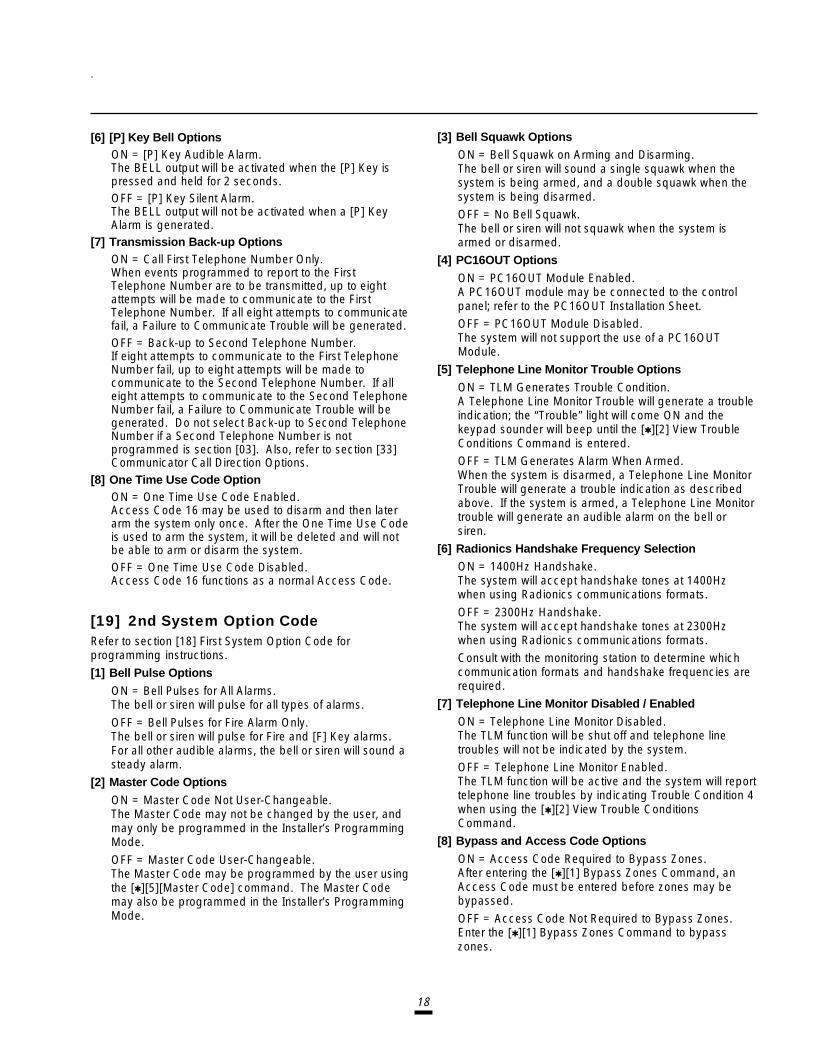
[6] [P] Key Bell OptionsON = [P] Key Audible Alarm.The BELL output will be activated when the [P] Key ispressed and held for 2 seconds.OFF = [P] Key Silent Alarm.The BELL output will not be activated when a [P] KeyAlarm is generated.
[7] Transmission Back-up OptionsON = Call First Telephone Number Only.When events programmed to report to the FirstTelephone Number are to be transmitted, up to eightattempts will be made to communicate to the FirstTelephone Number. If all eight attempts to communicatefail, a Failure to Communicate Trouble will be generated.OFF = Back-up to Second Telephone Number.If eight attempts to communicate to the First TelephoneNumber fail, up to eight attempts will be made tocommunicate to the Second Telephone Number. If alleight attempts to communicate to the Second TelephoneNumber fail, a Failure to Communicate Trouble will begenerated. Do not select Back-up to Second TelephoneNumber if a Second Telephone Number is notprogrammed is section [03]. Also, refer to section [33]Communicator Call Direction Options.
[8] One Time Use Code OptionON = One Time Use Code Enabled.Access Code 16 may be used to disarm and then laterarm the system only once. After the One Time Use Codeis used to arm the system, it will be deleted and will notbe able to arm or disarm the system.OFF = One Time Use Code Disabled.Access Code 16 functions as a normal Access Code.
[19] 2nd System Option CodeRefer to section [18] First System Option Code forprogramming instructions.[1] Bell Pulse Options
ON = Bell Pulses for All Alarms.The bell or siren will pulse for all types of alarms.
OFF = Bell Pulses for Fire Alarm Only.The bell or siren will pulse for Fire and [F] Key alarms.For all other audible alarms, the bell or siren will sound asteady alarm.
[2] Master Code Options
ON = Master Code Not User-Changeable.The Master Code may not be changed by the user, andmay only be programmed in the Installer’s ProgrammingMode.
OFF = Master Code User-Changeable.The Master Code may be programmed by the user usingthe [Q][5][Master Code] command. The Master Codemay also be programmed in the Installer’s ProgrammingMode.
[3] Bell Squawk Options
ON = Bell Squawk on Arming and Disarming.The bell or siren will sound a single squawk when thesystem is being armed, and a double squawk when thesystem is being disarmed.OFF = No Bell Squawk.The bell or siren will not squawk when the system isarmed or disarmed.
[4] PC16OUT Options
ON = PC16OUT Module Enabled.A PC16OUT module may be connected to the controlpanel; refer to the PC16OUT Installation Sheet.OFF = PC16OUT Module Disabled.The system will not support the use of a PC16OUTModule.
[5] Telephone Line Monitor Trouble Options
ON = TLM Generates Trouble Condition.A Telephone Line Monitor Trouble will generate a troubleindication; the “Trouble” light will come ON and thekeypad sounder will beep until the [Q][2] View TroubleConditions Command is entered.OFF = TLM Generates Alarm When Armed.When the system is disarmed, a Telephone Line MonitorTrouble will generate a trouble indication as describedabove. If the system is armed, a Telephone Line Monitortrouble will generate an audible alarm on the bell orsiren.
[6] Radionics Handshake Frequency Selection
ON = 1400Hz Handshake.The system will accept handshake tones at 1400Hzwhen using Radionics communications formats.
OFF = 2300Hz Handshake.The system will accept handshake tones at 2300Hzwhen using Radionics communications formats.Consult with the monitoring station to determine whichcommunication formats and handshake frequencies arerequired.
[7] Telephone Line Monitor Disabled / Enabled
ON = Telephone Line Monitor Disabled.The TLM function will be shut off and telephone linetroubles will not be indicated by the system.OFF = Telephone Line Monitor Enabled.The TLM function will be active and the system will reporttelephone line troubles by indicating Trouble Condition 4when using the [Q][2] View Trouble ConditionsCommand.
[8] Bypass and Access Code Options
ON = Access Code Required to Bypass Zones.After entering the [Q][1] Bypass Zones Command, anAccess Code must be entered before zones may bebypassed.
OFF = Access Code Not Required to Bypass Zones.Enter the [Q][1] Bypass Zones Command to bypasszones.

19
If a test transmission fails to communicate after allattempts and a Fail To Communicate Trouble isgenerated, then that reporting code is erased from thebuffer and will not be transmitted with the next successfulcommunication.
[23] System Clock TimesAfter the section number [23] is entered, two 4 digit numbersare expected. These numbers are the following systemtimes:• Automatic arming time of day (HH:MM)• Test transmission time of day (HH:MM)
Times are entered using the “24 hour clock” (military time).Valid entries are 00 to 23 for HH (i.e. hours) and 00 to 59 forMM (i.e. minutes). Note: IF INVALID TIMES AREENTERED FUNCTIONS WILL NOT WORK. The automaticarm function is enabled and disabled using the[Q][6][Master Code] User’s Functions Command.
[24] New Installer’s Code
[25] New Master Code (Access Code Number 1)
[26] Downloading Access CodeEnter a new 4 digit code in each of sections 24, 25 and 26once the section number has been entered. Only use digits0 to 9 as code numbers. Do not press the [Q] or [#] keys.Note: If an error is made in entering a code, continue toenter the four digits then enter the section number againand re-enter the correct code. Do not press the [ Q] or [#]while entering these codes. Do not make any of the threecodes the same.
[27] Communicator Format OptionsThis section sets the type of format which will be sent to eachof the two telephone numbers programmed in sections [1]and [3]. Enter one HEX digit (i.e. when entering HEX “A”press [Q][1][Q]) for each. The number entered for eachphone number is determined by the requirements of thereceiver being called. Enter the format number for the “1stTelephone Number” first. It is necessary to program theformat number for each telephone number even if the firstphone number is the only one being used. Options are asfollows.
[0] Silent Knight/Ademco slow, 10 BPS (1400 Hzhandshake) 3/1 and 4/1, 4/2 non extended format
[1] Sescoa, Franklin, DCI, Vertex, 20 BPS (2300 Hzhandshake) 3/1 and 4/1, 4/2 non extended format
[2] Silent Knight fast, 20 BPS (1400 Hz handshake)3/1 and 4/1, 4/2 non extended format
[20] Zones 1 to 8 Bypass MaskUse the same method of programming as used in section[18]. Using this section it is possible to control which zonesthe user is able to bypass using the [Q][1] command. If thezone light is on the zone can be bypassed. If the zone light isoff that zone cannot be bypassed.
[21] Zones 9 to 16 Bypass MaskUse same method of programming as used in section [20].
Note: Zone lights 1 to 8 represent zones 9 to 16 in thissection, to allow single digit entry.
[22] System TimesOnce the section number is entered, 6 three digit numbersare expected to be entered. The valid range for entries in thissection is 001 to 255. Hex values or 000 are not allowed. Thetimes are entered in the following order:• Entry delay time (in seconds)
• Exit delay time (in seconds)
• Bell cut off time (in minutes)• Delay before AC failure trouble reporting (in minutes)
• Slow loop response time (in 10 ms increments)Default loop response - 500 ms
• Test transmission/periodic download cycle time (in days)
AC Failure Reporting Code is transmitted after the delayprogrammed, which may be up to 255 minutes. Thereporting code for AC Failure Trouble is programmed insections [09] and [10].
The Zone Response Time is the length of time that analarm condition must be present on a zone before it isdetected. Certain vibration detectors, shock sensors andglass break detectors require a fast response zone inorder to operate. The zones to which these types ofdetectors are connected should be programmed as fastresponse zones. All other zones should be programmedas slow response zones. Zones are defined as either fastor slow response time in Section [16]. The fast responsetime is fixed at 10 milliseconds. The Slow Zone ResponseTime is programmable in increments of 10 milliseconds.The normal entry would be 50 for a 500 ms slow responsetime.
A Test Transmission or a Periodic Download may bedone according to how section [49] light 8 is set. The testtransmission and periodic download both use the samecycle time which is set in section [22] and the same timeof day as set in section [23]. The test transmission is sentto the monitoring station to confirm that thecommunication link is intact. The reporting code must beprogrammed in section [15]. The periodic download mustbe used in conjunction with the downloading computer“waiting for a panel to call”.
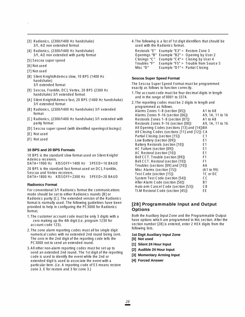
20
[3] Radionics, (2300/1400 Hz handshake)3/1, 4/2 non extended format
[4] Radionics, (2300/1400 Hz handshake)3/1, 4/2 non extended with parity format
[5] Sescoa super speed[6] Not used
[7] Not used
[8] Silent Knight/Ademco slow, 10 BPS (1400 Hzhandshake)3/1 extended format
[9] Sescoa, Franklin, DCI, Vertex, 20 BPS (2300 Hzhandshake) 3/1 extended format
[A] Silent Knight/Ademco fast, 20 BPS (1400 Hz handshake)3/1 extended format
[B] Radionics, (2300/1400 Hz handshake) 3/1 extendedformat
[C] Radionics, (2300/1400 Hz handshake) 3/1 extended withparity format
[D] Sescoa super speed (with identified openings/closings)
[E] Not used[F] Not used
10 BPS and 20 BPS Formats
10 BPS is the standard slow format used on Silent Knight/Ademco receivers.DATA=1900 Hz KISSOFF=1400 Hz SPEED=10 BAUD
20 BPS is the standard fast format used on DCI, Franklin,Sescoa and Vertex receivers.DATA=1800 Hz KISSOFF=2300 Hz SPEED=20 BAUD
Radionics Format
For conventional 3/1 Radionics format the communicationsmode should be set to either Radionics rounds [B] orRadionics parity [C]. The extended version of the Radionicsformat is normally used. The following guidelines have beenprovided to help in configuring the PC3000 for Radionicsformat.1.The customer account code must be only 3 digits with a
zero making up the 4th digit (i.e. program 1230 foraccount code 123).
2.The zone alarm reporting codes must all be single digitnumerical codes with no extended 2nd round being sent.The zero in the 2nd digit of the reporting code tells thePC3000 not to send an extended round.
3.All other non-alarm reporting codes must be set up tosend an extended 2nd round. The 1st digit of the reportingcode is used to identify the event while the 2nd orextended digit is used to associate the event with aparticular item. (i.e. A reporting code of E3 means restorezone 3. E for restore and 3 for zone 3.)
4.The following is a list of 1st digit identifiers that should beused with the Radionics format.
Restorals “E” Example “E3” = Restore Zone 3Openings “B” Example “B2” = Opening by User 2Closings “C” Example “C4” = Closing by User 4Troubles “F” Example “F5” = Trouble from Source 5Misc “D” Example “D1” = Partial Closing
Sescoa Super Speed Format
The Sescoa Super Speed Format must be programmedexactly as follows to function correctly.1.The account code must be four decimal digits in length
and in the range of 0001 to 3374.
2.The reporting codes must be 2 digits in length andprogrammed as follows.Alarms Zones 1- 8 (section [05]) A1 to A8Alarms Zones 9 -16 (section [06]) A9, 1A, 11 to 16Restorals Zones 1- 8 (section [07]) A1 to A8Restorals Zones 9 -16 (section [08]) A9, 1A, 11 to 16All Opening Codes (sections [13] and [14])BAAll Closing Codes (sections [11] and [12]) CAPartial Closing (section [15]) C1Low Battery (section [09]) E1Battery Restorals (section [10]) E1AC Failure (section [09]) E1AC Restoral (section [10]) E1Bell CCT. Trouble (section [09]) F1Bell CCT. Restoral (section [10]) F1Troubles (sections [09] and [10]) AAMisc Alarms (section [15]) (A1 to 99)Test Code (section [15]) 1C or DCSystem Test Code (section [54]) CCAfter Alarm Code (section [50]) B1Auto-arm Cancel Code (section [53]) C8TLM Restoral Code (section [45]) EE
[28] Programmable Input and OutputOptionsBoth the Auxiliary Input Zone and the Programmable Outputhave options which are programmed in this section. After thesection number [28] is entered, enter 2 HEX digits from thefollowing lists.
1st Digit Auxiliary Input Zone[0] Not used
[1] Silent 24 Hour Input[2] Audible 24 Hour Input
[3] Momentary Arming Input
[4] Forced Answer

21
When option [4] is selected, a high input (+12 V) will forcethe panel to pick up the phone line and awaitcommunications from downloading. This option is used foron-site downloading or for use with the LINKS 1000 CellularAlarm Transmitter.
See Auxiliary Input Terminal in the “Terminal Connections”section on page 4 for details on the Auxiliary Input. Whenoption [3] is selected, a momentary key closure between theAuxiliary Input and the Positive Auxiliary Power Supply willalternately arm and disarm the system. The reporting codesfor the Auxiliary Input (sections [9] and [10]) can be used asopening and closing codes for key arming but will only betransmitted with side A openings and closings.
2nd Digit Programmable OutputSee programmable Output Terminal in the “TerminalConnections” section on page 4 for details on connectingthe “PGM OUT” terminal.
[0] LINKS Support Output . Select this option if a LINKS1000 Cellular Alarm Transmitter is to be used with thepanel. The PGM output terminal is used to control theLINKS 1000. The PGM output will activate the LINKS1000 after an unsuccessful communication attempt onthe regular phone line.
[1] Ground Start Pulse provides a 2 second ground startpulse before dialing begins to obtain the dial tone onground start telephone equipment.
[2] Utility Output ([ Q], [7]) no access code[3] Utility Output ([ Q], [7]) any access code
[4] Utility Output ([ Q], [7]) Group A access code
[5] Utility Output ([ Q], [7]) Group B access codeThese options change the “PGM OUT” terminal to differentoptions used with the keypad utility output [Q][7] command.See Utility Output Command in the “Keypad Command”section.
[6] Keypad Buzzer Follow Mode . With this option the “PGMOUT” terminal switches to ground as long as the keypadbuzzer is on.
[7] System Status (Arm/Disarm) Output . With this optionthe “PGM OUT” terminal switches to ground when thepanel is armed. The switch is open when the panel isdisarmed.
[8] Strobe Output (latched alarm output) . With this optionthe “PGM OUT” terminal switches to ground after analarm and remains switched on until the system isdisarmed.
[9] Failure to Communicate Output . With this option the“PGM OUT” terminal switches to ground if the systemfails to communicate with the monitoring station after 8attempts. The output stays switched to ground until asuccessful communication takes place or until trouble #5is cleared from the keypad. This option may be used totie two systems together. One system can then be madeto report a communication failure for the other.
[A] TLM and Alarm . With this option the “PGM OUT” terminalswitches to ground if the system has a TLM fault and anyalarm condition. The output follows the length of ‘bell timeout’.
[B] Courtesy Pulse . With this option the “PGM OUT”terminal switches to ground during the course of theentry and exit times. It could be used to turn on a lightnear the exit for the duration of the entry/exit times.
[C] PGM Squawk Output must be selected in order to usePGM Squawk on Entry/Exit Delay options in section [60].
[D] 2nd Line Slave . With this option the “PGM OUT” terminalswitches to ground after four unsuccessful attempts havebeen made to the phone number being dialed. Theoutput will stay switched until the panel has hung-up.This could be used to switch the panel to a backup set ofphone lines.
[E] Kissoff Output . With this option the “PGM OUT” terminalswitches to ground after the kissoff has been received tocomplete a “successful” communication to the centralstation. The terminal switches to ground for 2 seconds.
[F] Remote Operation ..... With this option the “PGM OUT”terminal can be switched remotely using the DLS-1software (version 5.3 or later).
[29] [30] [31] [32] Split Arming“Split Arming” feature permits a single control panel to act astwo independent alarm systems, each with its own openingand closing schedules, zone assignments and authorizedusers.The allowable zone and access code assignments to systemA or system B are described below. Typically, zones andaccess codes are assigned to either Group A or Group B butthe PC3000 can be programmed for zones and accesscodes that are common to both Group A and Group B.The following four sections are each programmed the sameas section [18].Split System Zone and Access Assignments[29] Group A Zone Assignment for Zones 1 to 8.
Note: Zones 9 to 16 are always assigned to Group A.[30] Group B Zone Assignment for Zones 1 to 8.
Note: Zones 9 to 16 cannot be assigned to Group B.[31] Group A Access Code Assignment for Codes 1 to 8.
Note: Codes 9 to 16 are always assigned to Group A.[32] Group B Access Code Assignment for Codes 1 to 8.
Note: Codes 9 to 16 cannot be assigned to Group B.
Common ZonesIf a zone (1 through 8 only) is assigned to both Group A andGroup B then both Group A and Group B must be armed forthat zone to be armed.
Common Access CodeIf an access code (1 through 8 only) is assigned to Group Aand Group B then that access code will arm and disarm theentire panel.

22
Armed Status IndicationsWhen the panel is established as a split system, and ONEside only [Group A or B] is armed, the “Armed” indicator willflash and the zone indicators for the group that has beenarmed will flash.If both Group A and Group B are armed the “Armed”indicator will be on steadily and the zone lights will not flash.
Zone Bypassing Access CodeWhen the system is established for split arming, user zonebypassing should be set so that bypassing requires the useof an access code. (See section [19].)
CommunicatorWhen the PC3000 is set up for “split arming” and both GroupA and Group B systems are reporting to the same telephonenumber, Group A burglar alarms and restorals areprogrammed as [1] in section [33] to call the 1st phonenumber only. Light 7 in section [18] must be turned “ON”.
Group B burglar alarms and restorals are programmed witha [2] in Section [33] to call the 2nd phone number only. It isnecessary to program both the 1st and 2nd phone numberlocations with the same telephone number.Notes:1.The following restrictions apply to split arming
applications:• The Master Code must be assigned to side A and B.• All codes and zones must be assigned even if not
used.• Transmission delay must not be used.• Home-away zones must not be used.• The “One-Time Use” code must not be used.• Exit Delay Termination must not be used. (section [60]
Light [7] OFF)• Closing confirmation must not be used. (section [60]
Light [6] OFF)• Quick Exit must not be used.• Alarms displayed while armed must not be used.• Audible Exit Fault must not be enabled.
2.PGM OUT Option A will work in a fully armed or fullydisarmed system.
3.Keyswitch arming will report with side A openings andclosings only.
[33] Communicator Call DirectionOptionsProgramming this section tells the dialer whether to sendtransmissions to the 1st or 2nd telephone number.There are four classes of dialer call direction options.
[0] No transmission for this group
[1] Call 1st phone number with back up to 2nd number[2] Call 2nd phone number only
[3] Always call both phone numbersOption [1] becomes “Call 1st number only” when item [7] insection [18] is turned on (LIGHT ON). Do not programbackup to 2nd phone number in section [18] unless a 2ndphone number is programmed.After entering the section number, enter [0], [1], [2] or [3] foreach of the following reporting code groups in the ordergiven (total of six digits).• Zone Group A Alarms and Restorals• Zone Group B Alarms and Restorals• Access Codes Group A Openings and Closings• Access Codes Group B Openings and Closings• Priority Alarms and Restorals• Maintenance Alarms and Restorals
Where all reporting codes are to be sent to one telephonenumber, enter [1] for all of the above groups.
[34] Software Reset EEPROM Memory toFactory DefaultsThis section is used to reset the EEPROM memory to theoriginal factory default values. As soon as [34] is entered theEEPROM is reset and the program is restarted as thoughpower has just been applied.
Hardware Reset of EEPROM Memory to Factory Defaults
If the Installer’s Code is lost through inadvertentprogramming, the only means of reprogramming the systemis via a hardware reset. If the Installer’s Lockout is enabled,there is no way to reprogram the system without entering thecorrect Installer’s Code.Follow the sequence outlined below to reset the panel tofactory default conditions.1.Power unit down by removing both AC and battery power.2.Using a short jumper, short pins marked “EEPROM
RESET” together.3.Power PC3000 up.4.Wait for 10 seconds. During this time the “Program” light
will flash.5.Remove the shorting jumper.6.The system will have reloaded the EEPROM with the
factory default codes.
[35] Through [42] Reserved for FutureUse
[43] Access Bypass Mask (Codes 1 to 8)Use the same method of programming as used in section[18]. In this section it is possible to control which users canbypass zones. If the zone light is on, that user can bypass, ifthat zone light is off, that user cannot bypass.

23
[44] Access Bypass Mask (Codes 9 to 16)Program using the same method as section [43].
Note: Zone lights 1 to 8 represent access codes 9 to 16.
[45] TLM Restoral Reporting CodeOnce the code is programmed, the panel will transmit thereporting code every time that a phone line trouble isrestored. This will also initiate transmission of all codesunsuccessfully transmitted during the phone line fault.
[46] Downloading Computer TelephoneNumberThis is the telephone number that the panel would use to callthe downloading computer if the CALLBACK feature (section[47]) is enabled or if a user initiated call up is done.([Q]+[6]+[ Master Code]+[ 9]).
[47] Modem Configuration[1] - [4] Zone Lights 1 through 4 are used to determine the
number of rings before the system will answer anincoming call for downloading. Refer to theProgramming Worksheets for information onprogramming Zone Lights 1 through 4.
[5] Downloading Answer Enabled / Disabled
ON = Downloading Answer Enabled.The system will answer calls for downloading after thenumber of rings programmed with Zone Lights 1 through 4.
OFF = Downloading Answer Disabled.The system will not answer incoming calls. WithDownloading Answer disabled, downloading must beperformed with the User Call-up or Periodic Downloadingfunctions.
[6] User Call-up Enabled / Disabled
ON = User Call-up Enabled.The user can have the system call the downloadingcomputer by entering the [Q][6][Master Code][9]Command. For the User Call-up Command to function, aDownloading Computer Telephone Number and a PanelIdentification Code need to be programmed.OFF = User Call-up Disabled.
[7] Answering Machine Over-ride Enabled / Disabled
ON = Answering Machine Over-ride Enabled.The system may be connected to the same telephone lineas an answering machine. To over-ride the answeringmachine, have the downloading computer call the systemand let the telephone line ring only once or twice. After oneor two rings, hang up. If the system is called back within thetime set in section [51] with Zone Light 7, the system willanswer the next call on the first ring. Refer to section [51]Third System Option Code, Light 7 Answering MachineOver-ride Timer Option.
OFF = Answering Machine Over-ride Disabled. Thesystem will only answer incoming calls after the numberof rings programmed with Zone Lights 1 through 4.
[8] Downloading Call Back Enabled / Disabled
ON = Downloading Call Back Enabled. When the system answers the downloading computer’scall, both the computer and the system will hang up.The system will then call the Downloading TelephoneNumber and connect with the computer at that number.If more than one downloading computer is to be used,this function should be disabled.OFF = Downloading Call Back Disabled.The downloading computer will have immediate accessto the system once the system is identified as a validsystem.
[48] Panel Identification CodeProgram using the same method as sections [24], [25] and[26].
[49] 4th System Option Code[1] For Future Use.
Note: Zone Light 1 must be OFF at all times.[2] Fire Zone Connection Options
ON = Fire Zone Connected to SW AUX.Smoke detectors on the Fire Zone are powered from theSW AUX terminal. When the [Q][4] Command is entered,power will be removed from the smoke detectors to allowthem to be reset. When the [Q][4] Command is used, theFire Zone Trouble normally generated from a powersupervision relay when power is removed from thesmoke detector is not displayed or communicated.OFF = Fire Zone Not Connected to SW AUX.Smoke detectors on the Fire Zone are not powered fromthe SW AUX terminal. If the [Q][4] Command is entered,Trouble Condition 4 (Fire Zone Trouble) will be displayedand reported to the monitoring station.
[3] Escort Access Code OptionsON = Escort Requires Master Code.The Escort Voice Assisted Security Control Module willonly allow remote access to the system if the MasterCode is entered.OFF = Escort Accepts Any Access Code.The Escort Voice Assisted Security Control Module willallow remote access to the system for any valid AccessCode.
[4] For Future Use.
[5] For Future Use.
[6] For Future Use.[7] For Future Use.

24
[8] Periodic Downloading and Test Transmission Options
ON = Periodic Downloading Enabled.The system will automatically place a call to thedownloading computer at the time programmed in theSystem Clock Times and at the interval, in days,programmed in the System Times. A DownloadingTelephone Number must be programmed in theDownloading Computer Telephone Number section.
OFF = Periodic Test Transmission Enabled.The system will automatically call the ProgrammedMaintenance Telephone Number(s) and transmit the TestReporting Code programmed in the Maintenance AlarmsReporting Codes section at the time programmed in theSystem Clock Times and at the interval, in days,programmed in the System Times.
[50] After Alarm Reporting CodeProgram using the same method as sections [05] to [15].This code will be transmitted with or instead of an openingcode if an alarm occurred during the last armed state. ‘00’ or‘FF’ in this section will disable the feature.
[51] 3rd System Option Code[1] Bell During Auto-Arm Options
ON = Bell During Auto-Arm Disabled.The bell or siren will not be activated during the 1-minuteAuto-Arm warning time.
OFF = Bell During Auto-Arm Enabled.The bell or siren will sound a single squawk every 10seconds during the 1-minute Auto-Arm warning time.
[2] Auto-Arm Cancellation Options
ON = Access Code Required to Cancel Auto-Arming.An Access Code must be entered to cancel the Auto-Arm sequence during the 1-minute Auto-Arm Warningtime.
OFF = Any Keypress will Cancel Auto-Arming.Pressing any key during the 1-minute Auto-Arm Warningtime will cancel the Auto-Arming sequence.
[3] 2-minute Keypad Time-out Enabled / Disabled
ON = 2-minute Keypad Time-out Enabled.If no keys are pressed for 2 minutes, all keypad lights willbe shut OFF. NOTE: This feature must not be usedNOTE: This feature must not be usedNOTE: This feature must not be usedNOTE: This feature must not be usedNOTE: This feature must not be usedwith LCD keypads or the Escort module.with LCD keypads or the Escort module.with LCD keypads or the Escort module.with LCD keypads or the Escort module.with LCD keypads or the Escort module.OFF = No Keypad Time-out.The keypad lights will remain ON at all times.
[4] [P] Key Keypad Sounder Options
ON = Keypad Silent for [P] Key.When a [P] Key alarm is generated, the keypad sounderwill not beep to acknowledge the alarm.
OFF = Keypad Audible for [P] Key.When a [P] Key alarm is generated, the keypad sounderwill beep 3 times to acknowledge the alarm.
[5] [F] Key Enabled / Disabled
ON = [F] Key Disabled.The [F] Key will not sound an alarm when pressed.OFF = [F] Key Enabled.Pressing and holding the [F] Key for 2 seconds willgenerate a Fire alarm; the bell or siren will sound with apulsing tone, and an alarm reporting code (ifprogrammed) will be transmitted.
[6] Quick-Exit Enabled / Disabled
ON = Quick-Exit Enabled.With the system armed in the Home-Away mode, usersmay enter the [Q][0] Command to allow a single DelayZone to be activated so they may leave the premises.Only one Delay Zone may be activated; any additionalactivity on another Delay Zone will generate an alarm. Ifthe Delay zone is still open two minutes after the [Q][0]command is entered, the Entry Delay will be initiated.OFF = Quick-Exit Disabled.
[7] Answering Machine Over-ride Timer OptionON = Over-ride Timer set for 120 seconds.When ON, the delay between the first and second callsfrom the downloading computer may not exceed 120seconds. Refer to section [47] Light 7 for information onhow to use the Answering Machine Over-ride function.OFF = Over-ride Timer set for 60 seconds.When OFF, the delay between the first and second callsfrom the downloading computer may not exceed 60seconds.
[8] Bell Shutdown Enabled / DisabledON = Bell Shutdown Enabled.The BELL output will not be activated for zones that haveexceeded the limit of alarms set in the Swinger Shutdowncounter.OFF = Bell Shutdown Disabled.The BELL output will be activated for all alarms on allzones, even after the Swinger Shutdown counter hasbeen exceeded. The BELL output will continue to beactivated for all alarms, even though the alarms will notbe reported once the Swinger Shutdown counter hasbeen exceeded.
[52] Delay Before TransmissionProgram the same as section [22]. This section defines howlong in seconds a burglary zone will wait before transmittingan alarm. The fire zone and 24 hour zones do not have adelay. The time may be programmed from 00 to 99 secondswhere 00 means no delay. If the system is disarmed beforethe delay in transmission expires, no transmission will takeplace.

25
[53] Auto-arm Cancel Reporting CodeThis code is programmed the same as section [50]. Once areporting code has been programmed into this section, it willbe transmitted any time an auto-arm is cancelled to informthe station that auto-arm has been cancelled for that day.
[54] System Test Reporting CodeThis code is programmed the same as section [50]. Oncethis section is programmed, the code will be sent every timea bell test is done ([Q]+[6]+[Master Code]+[8]).
[55] TLM Trouble Reporting CodeThis reporting code can be transmitted to the monitoringstation through a LINKS 1000 Cellular Alarm Transmitter,when a TLM trouble occurs on the regular phone lines.Leave this section blank if there is no LINKS unit connected.See section [05] for programming reporting codes and“Trouble Display [Q]+[2]” for a description of TLM trouble.
[56] LINKS Test Transmission ReportingCodeThis reporting code is transmitted to the monitoring stationthrough a LINKS 1000 Cellular Alarm Transmitter periodicallyfor testing the cellular communications. The cellular testtransmission occurs at the same time as the regular testtransmission. The test transmission time is programmed insections [22] and [23]. After the cellular test transmission iscompleted, the periodic test transmission reporting codeprogrammed in section [15] will be transmitted through theregular phone lines.
LINKS 1000 Preamble Codes
They are 4-digit codes used with long distance telephonenumbers that are dialled through the LINKS module. Thesecodes are used for programming area codes in cases wherea land line telephone number may be a local call, while thecellular telephone number dialled by the LINKS 1000 moduleis a long distance call.
In the following sections [57], [58] and [59], program 4-digitPreambles for the Phone Numbers. Program all unuseddigits with hexadecimal “F”.
[57] LINKS 1000 Preamble for1st Phone Number
[58] LINKS 1000 Preamble for2nd Phone Number
[59] LINKS 1000 Preamble forDownloading Phone Number
[60] 6th System Option Code[1] PGM Squawk on Exit Options
ON = PGM Squawk on Exit Delay.The PGM output will pulse during the Exit Delay Time. Ifthe Urgency on Exit Delay function described below isenabled, the PGM pulse will be quickened for the last 10seconds of the Exit Delay.
OFF = No PGM Squawk on Exit Delay.
Note: Option C must be selected for the PGM outputin section [28].
[2] PGM Squawk on Entry Options
ON = PGM Squawk on Entry Delay.The PGM output will pulse during the Entry Delay Time.If the Urgency on Entry Delay function described belowis enabled, the PGM pulse will be quickened for the last10 seconds of the Entry Delay.
OFF = No PGM Squawk on Entry Delay.Note: Option C must be selected for the PGM outputin section [28].
[3] Audible Exit Fault Enabled / Disabled
ON = Audible Exit Fault Enabled.If a Delay Zone is left open at the end of the Exit Delay,the Entry Delay will begin immediately and the bell orsiren will sound a steady alarm. This feature is designedto immediately alert the user that their system has beenarmed incorrectly.
OFF = Audible Exit Fault Disabled.If a Delay Zone is left open at the end of the Exit Delay,the Entry Delay will begin immediately. If the system isnot disarmed before the end of the Entry Delay, an alarmwill be generated.
[4] Exit Delay Urgency Tone Option
ON = Exit Delay Urgency Tone Enabled.The Keypad will sound a pulsing tone during the ExitDelay. During the last 10 seconds of the Exit Delay, thekeypad will sound a faster pulsing tone to warn that theExit Delay is about to expire.
OFF = Normal Exit Delay Tone.The Keypad will sound a pulsed tone throughout the ExitDelay time.
[5] Entry Delay Urgency Tone Option
ON = Entry Delay Urgency Tone Enabled.The Keypad will sound a steady tone during the EntryDelay. During the last 10 seconds of the Entry Delay, thekeypad will sound a pulsing tone to warn that the EntryDelay is about to expire.
OFF = Normal Entry Delay Tone.The Keypad will sound a steady tone throughout theEntry Delay time.

26
[6] Closing Confirmation Enabled / Disabled
ON = Closing Confirmation Enabled. When an AccessCode is entered to arm the system, the Exit Delay timewill not begin until one of the following events occurs:
• The closing is successfully transmitted to themonitoring station. When the closing is transmitted, thekeypad will sound an acknowledgement tone toindicate that the monitoring station has been advised ofthe closing. The Exit Delay will then begin.
• The closing is not successfully transmitted to themonitoring station. If the closing cannot be transmitted,a Failure To Communicate Trouble will be generated.The Exit Delay time will begin once the troublecondition is indicated on the keypad.
• The user may re-enter their Access Code to initiate theExit Delay
OFF = Closing Confirmation Disabled.The Exit Delay time will commence once an AccessCode is entered to arm the system.Notes:• Back-up to Second Telephone Number cannot be
used with the Closing Confirmation feature.• The Closing Confirmation feature cannot be used
with the Escort Voice Assisted Security Module.• The Closing Confirmation feature cannot be used
with Split Arming. (sections [29] to [32])• The Closing Confirmation feature cannot be
used with the Exit Delay Termination feature.(section [60] Light [7] OFF)
[7] Exit Delay Termination Enabled / Disabled
ON = Exit Delay Termination Enabled.The Exit Delay will be terminated once the Delay Zone forthe entry/exit door or area is restored. All audible optionsassociated with the Exit Delay will be silenced when theExit Delay is terminated.
OFF = Normal Exit Delay.The Exit Delay timer will continue to count even after theDelay Zone for the entry/exit door or area is restored. Allaudible options associated with the Exit Delay willfunction until the time programmed for the Exit Delay haselapsed.Notes:• Split Arming cannot be used with the Exit Delay
Termination feature. (sections [29] to [32])• Closing Confirmation cannot be used with the Exit
Delay Termination feature. (section [60] Light [6]OFF)
[8] For Future Use
OFF = Zone Light 8 must be OFF at all times.1
[90] Installer’s Lockout EnableThis feature is enabled by entering [90] while in the Installer’sProgramming mode. A factory default (hardware or software)will not reset the Installer’s Code or the download accesscode once this feature is enabled. A panel that has thislockout feature enabled will give a distinctive audibleindication upon power up. This indication is the phone linerelay clicking ten times. Make sure that your new Installer’sCode has been entered correctly before enabling thisfeature because there is no way of re-entering theprogramming mode without the new Installer’s Code. Even areset to the factory default will not change the Installer’sCode back to default.
[91] Installer’s Lockout DisableEntering [91] when in the Installer’s Programming mode willdisable the Installer’s Lockout feature.
Note: Panels returned to DSC with the Installer’s Lockoutfeature enabled and no other apparent problems will besubject to an additional service charge.
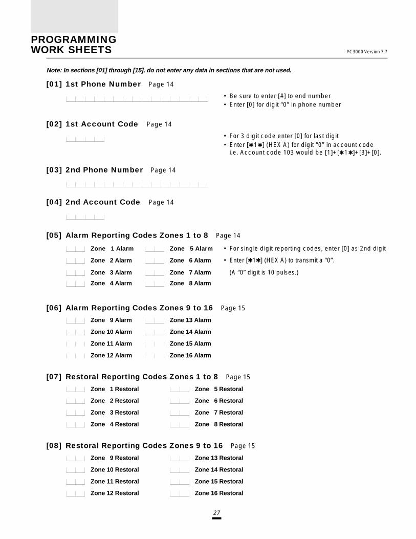
27
PROGRAMMINGWORK SHEETS PC3000 Version 7.7
Note: In sections [01] through [15], do not enter any data in sections that are not used.
[01] 1st Phone Number Page 14
• Be sure to enter [#] to end number• Enter [0] for digit “0” in phone number
[02] 1st Account Code Page 14
• For 3 digit code enter [0] for last digit• Enter [Q1Q] (HEX A) for digit “0” in account code
i.e. Account code 103 would be [1]+[Q1Q]+[3]+[0].
[03] 2nd Phone Number Page 14
[04] 2nd Account Code Page 14
[05] Alarm Reporting Codes Zones 1 to 8 Page 14
Zone 1 Alarm Zone 5 Alarm • For single digit reporting codes, enter [0] as 2nd digit
Zone 2 Alarm Zone 6 Alarm • Enter [Q1Q] (HEX A) to transmit a “0”.
Zone 3 Alarm Zone 7 Alarm (A “0” digit is 10 pulses.)
Zone 4 Alarm Zone 8 Alarm
[06] Alarm Reporting Codes Zones 9 to 16 Page 15
Zone 9 Alarm Zone 13 Alarm
Zone 10 Alarm Zone 14 Alarm
Zone 11 Alarm Zone 15 Alarm
Zone 12 Alarm Zone 16 Alarm
[07] Restoral Reporting Codes Zones 1 to 8 Page 15
Zone 1 Restoral Zone 5 Restoral
Zone 2 Restoral Zone 6 Restoral
Zone 3 Restoral Zone 7 Restoral
Zone 4 Restoral Zone 8 Restoral
[08] Restoral Reporting Codes Zones 9 to 16 Page 15
Zone 9 Restoral Zone 13 Restoral
Zone 10 Restoral Zone 14 Restoral
Zone 11 Restoral Zone 15 Restoral
Zone 12 Restoral Zone 16 Restoral

28
PC3000 Version 7.7
[09] Utility Alarm Reporting Codes Page 15
Fire Zone* * Priority alarms/restorals
Auxiliary Input Zone* or *** * * Maintenance alarms/restorals see section [33]
Battery Trouble** *** Transmission reports with sections [11] to [14]
AC Failure Trouble** (openings/closings)
Day Zone(s) Trouble**
Bell Circuit Trouble**
Fire Zone Trouble**
Auxiliary Power Supply Trouble**
[10] Utility Restoral Reporting Codes Page 15
Fire Zone* * Priority alarms/restorals
Auxiliary Input Zone* or *** * * Maintenance alarms/restorals see section [33]
Battery Trouble** *** Transmission reports with sections [11] to [14]
AC Failure Trouble** (openings/closings)
Day Zone(s) Trouble**
Bell Circuit Trouble**
Fire Zone Trouble**
Auxiliary Power Supply Trouble**
[11] Reporting Codes for Closing (Arming) via Access Codes 1 to 8 Page 15
Access Code 1 Access Code 5
Access Code 2 Access Code 6
Access Code 3 Access Code 7
Access Code 4 Access Code 8
[12] Reporting Codes for Closing (Arming) via Access Codes 9 to 16 Page 16
Access Code 9 Access Code 13
Access Code 10 Access Code 14
Access Code 11 Access Code 15
Access Code 12 Access Code 16
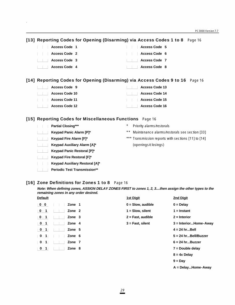
29
PC3000 Version 7.7
[13] Reporting Codes for Opening (Disarming) via Access Codes 1 to 8 Page 16
Access Code 1 Access Code 5
Access Code 2 Access Code 6
Access Code 3 Access Code 7
Access Code 4 Access Code 8
[14] Reporting Codes for Opening (Disarming) via Access Codes 9 to 16 Page 16
Access Code 9 Access Code 13
Access Code 10 Access Code 14
Access Code 11 Access Code 15
Access Code 12 Access Code 16
[15] Reporting Codes for Miscellaneous Functions Page 16
Partial Closing*** * Priority alarms/restorals
Keypad Panic Alarm [P]* * * Maintenance alarms/restorals see section [33]
Keypad Fire Alarm [F]* *** Transmission reports with sections [11] to [14]
Keypad Auxiliary Alarm [A]* (openings/closings)
Keypad Panic Restoral [P]*
Keypad Fire Restoral [F]*
Keypad Auxiliary Restoral [A]*
Periodic Test Transmission**
[16] Zone Definitions for Zones 1 to 8 Page 16Note: When defining zones, ASSIGN DELAY ZONES FIRST to zones 1, 2, 3....then assign the other types to theremaining zones in any order desired.Default 1st Digit 2nd Digit
0 0 Zone 1 0 = Slow, audible 0 = Delay
0 1 Zone 2 1 = Slow, silent 1 = Instant
0 1 Zone 3 2 = Fast, audible 2 = Interior
0 1 Zone 4 3 = Fast, silent 3 = Interior...Home-Away
0 1 Zone 5 4 = 24 hr...Bell
0 1 Zone 6 5 = 24 hr...Bell/Buzzer
0 1 Zone 7 6 = 24 hr...Buzzer
0 1 Zone 8 7 = Double delay
8 = 4x Delay
9 = Day
A = Delay...Home-Away

30
PC3000 Version 7.7
[17] Zone Definitions for Zones 9 to 16 Page 17Note: Zones 9-16 cannot be programmed for fast response - Do not use fast response devices on these loops.e.g. Vibration detectors.Default 1st Digit 2nd Digit
0 1 Zone 9 0 = Slow, audible 0 = Delay
0 1 Zone 10 1 = Slow, silent 1 = Instant
0 1 Zone 11 2 = Interior
0 1 Zone 12 3 = Interior...Home-Away
0 1 Zone 13 4 = 24 hr...Bell
0 1 Zone 14 5 = 24 hr...Bell/Buzzer
0 1 Zone 15 6 = 24 hr...Buzzer
0 1 Zone 16 7 = Double delay
8 = 4x Delay
9 = Day
A = Delay...Home-Away
[18] 1st System Option Code Page 17Default Zone Light On Zone Light Off
Off Zone Light 1 ......................... Communication disabled Communication enabled
Off Zone Light 2 ......................... Restorals on bell timeout Restorals on disarming
Off Zone Light 3 ......................... Alarm display while armed No alarm display/armed
Off Zone Light 4 ......................... DTMF dialing Pulse dialing
Off Zone Light 5 ......................... N/C loops EOL resistors loops
Off Zone Light 6 ......................... Keypad [P]anic audible Silent
On Zone Light 7 ......................... Call 1st phone only Back up to 2nd phone
Off Zone Light 8 ......................... 16th code = maid's code Normal code
[19] 2nd System Option Code Page 18Default Zone Light On Zone Light Off
Off Zone Light 1 ......................... Bell pulses always Bell pulses upon fire only
Off Zone Light 2 ......................... Master code not changeable Master code changeable
Off Zone Light 3 ......................... Bell squawk enabled Bell squawk disabled
Off Zone Light 4 ......................... PC16 OUT enabled PC16 OUT disabled
Off Zone Light 5 ......................... TLM trouble only TLM audible when armed
Off Zone Light 6 ......................... 1400Hz Radionics 2300Hz Radionics
Off Zone Light 7 ......................... TLM disabled TLM enabled
Off Zone Light 8 ......................... Access code req'd for bypass Access code not req'd

31
PC3000 Version 7.7
[20] Zones 1 to 8 Bypass Mask Page 19Default
On Zone Light 1
On Zone Light 2
On Zone Light 3
On Zone Light 4
On Zone Light 5
On Zone Light 6
On Zone Light 7
On Zone Light 8
[21] Zones 9 to 16 Bypass Mask Page 19Default
On Zone Light 1
On Zone Light 2
On Zone Light 3
On Zone Light 4
On Zone Light 5
On Zone Light 6
On Zone Light 7
On Zone Light 8
[22] System Times Page 19Default
0 3 0 Entry Delay Time (in seconds)
1 2 0 Exit Delay Time (in seconds)
0 0 4 Bell Cut-off Time (in minutes)
0 3 0 AC Failure Transmission Delay (in minutes)
0 5 0 Normal Loop Response Time (x 10 ms)
0 3 0 Test Transmission Cycle Time (in days)
[23] System Clock Times Page 19Default
9 9 9 9 Automatic Arming Time of Day
9 9 9 9 Test Transmission Time of Day
Note:If zone light is on, the zone can bebypassed using the [ Q] [1] command.
Note:If zone light is on, the zone can bebypassed using the [ Q] [1] command.
Notes:1.Valid entries are: 001 to 255.2.Do not enter “000” - it is not a valid entry.
Enter 4 digits: 00 to 23 hr, 00 to 59 min.If not used, leave at the factory defaultsettings.
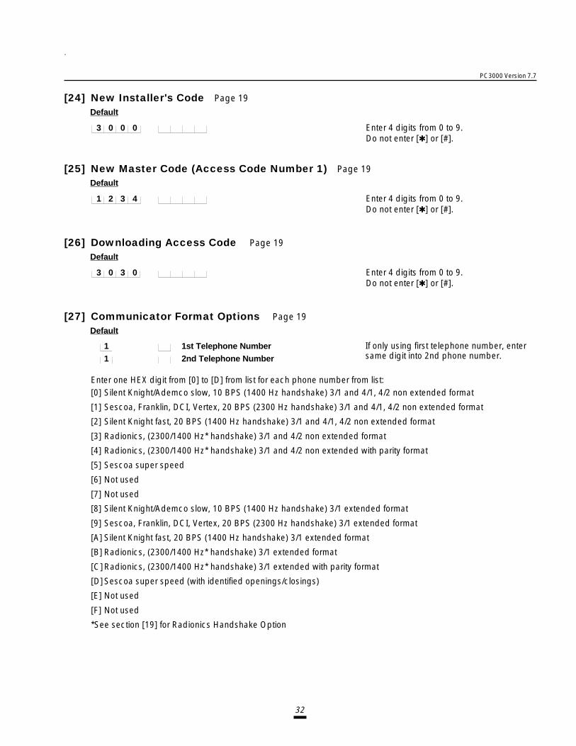
32
PC3000 Version 7.7
[24] New Installer's Code Page 19Default
3 0 0 0 Enter 4 digits from 0 to 9.Do not enter [Q] or [#].
[25] New Master Code (Access Code Number 1) Page 19Default
1 2 3 4 Enter 4 digits from 0 to 9.Do not enter [Q] or [#].
[26] Downloading Access Code Page 19Default
3 0 3 0 Enter 4 digits from 0 to 9.Do not enter [Q] or [#].
[27] Communicator Format Options Page 19Default
1 1st Telephone Number 1 2nd Telephone Number
Enter one HEX digit from [0] to [D] from list for each phone number from list:[0] Silent Knight/Ademco slow, 10 BPS (1400 Hz handshake) 3/1 and 4/1, 4/2 non extended format
[1] Sescoa, Franklin, DCI, Vertex, 20 BPS (2300 Hz handshake) 3/1 and 4/1, 4/2 non extended format
[2] Silent Knight fast, 20 BPS (1400 Hz handshake) 3/1 and 4/1, 4/2 non extended format
[3] Radionics, (2300/1400 Hz* handshake) 3/1 and 4/2 non extended format
[4] Radionics, (2300/1400 Hz* handshake) 3/1 and 4/2 non extended with parity format
[5] Sescoa super speed
[6] Not used
[7] Not used
[8] Silent Knight/Ademco slow, 10 BPS (1400 Hz handshake) 3/1 extended format
[9] Sescoa, Franklin, DCI, Vertex, 20 BPS (2300 Hz handshake) 3/1 extended format
[A] Silent Knight fast, 20 BPS (1400 Hz handshake) 3/1 extended format
[B] Radionics, (2300/1400 Hz* handshake) 3/1 extended format
[C]Radionics, (2300/1400 Hz* handshake) 3/1 extended with parity format
[D]Sescoa super speed (with identified openings/closings)
[E] Not used
[F] Not used
*See section [19] for Radionics Handshake Option
If only using first telephone number, entersame digit into 2nd phone number.

33
PC3000 Version 7.7
[28] Programmable Input and Output Options Page 20Default
2 Auxiliary Input Zone Enter 1, 2, 3 or 4 for options below 1, 2, 3 and 4 are(Normally open, momentary [0] Not used the only valid entriesclosure to “Aux +”) [1] Silent 24 hour input
[2] Audible 24 hour input[3] Momentary key arming[4] Forced answer
2 Programmable Output Enter 0 to F for options below 0 through F are(A 50 mA switch to ground.) [0] LINKS support output the only valid entriesNote: A relay must be used to [1] Ground start pulseobtain more current. [2] Utility output no access code
[3] Utility output any access code[4] Utility output Group A access code[5] Utility output Group B access code[6] Keypad buzzer follow mode[7] System status (arm/disarm) output[8] Strobe output (latched alarm output)[9] Failure to communicate output[A] TLM and alarm[B] Courtesy pulse[C]PGM squawk output[D]2nd line slave[E] Kissoff output[F] Remote operation (DLS-1 version 5.3 or later)
Note: Section [29]...[33] are used for split arming or split reporting only.
[29] Zone Group A Assignment Page 21Default
On Zone Light 1
On Zone Light 2
On Zone Light 3
On Zone Light 4
On Zone Light 5
On Zone Light 6
On Zone Light 7
On Zone Light 8
[30] Zone Group B Assignment Page 21Default
On Zone Light 1
On Zone Light 2
On Zone Light 3
On Zone Light 4
On Zone Light 5
On Zone Light 6
On Zone Light 7
On Zone Light 8
Note: If zone light is on that zone is assigned toGroup B.If light is on in both sections, the zone is common to bothsides and will only be armed if both sides are armed.
Note: If zone light is on that zone is assigned toGroup A.Zones 9 to 16 are permanently assigned to Group A.
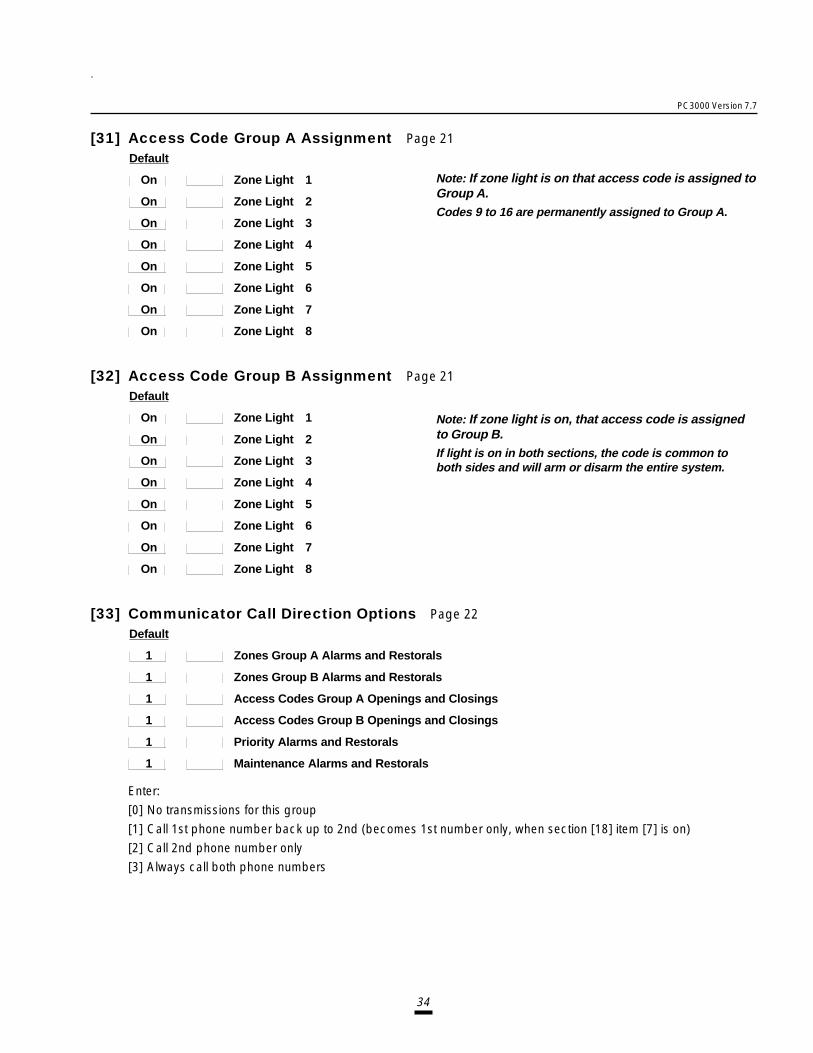
34
PC3000 Version 7.7
[31] Access Code Group A Assignment Page 21Default
On Zone Light 1
On Zone Light 2
On Zone Light 3
On Zone Light 4
On Zone Light 5
On Zone Light 6
On Zone Light 7
On Zone Light 8
[32] Access Code Group B Assignment Page 21Default
On Zone Light 1
On Zone Light 2
On Zone Light 3
On Zone Light 4
On Zone Light 5
On Zone Light 6
On Zone Light 7
On Zone Light 8
[33] Communicator Call Direction Options Page 22Default
1 Zones Group A Alarms and Restorals
1 Zones Group B Alarms and Restorals
1 Access Codes Group A Openings and Closings
1 Access Codes Group B Openings and Closings
1 Priority Alarms and Restorals
1 Maintenance Alarms and Restorals
Enter:
[0] No transmissions for this group
[1] Call 1st phone number back up to 2nd (becomes 1st number only, when section [18] item [7] is on)
[2] Call 2nd phone number only
[3] Always call both phone numbers
Note: If zone light is on that access code is assigned toGroup A.Codes 9 to 16 are permanently assigned to Group A.
Note: If zone light is on, that access code is assignedto Group B.If light is on in both sections, the code is common toboth sides and will arm or disarm the entire system.

35
PC3000 Version 7.7
[34] Software Reset EEPROM Memory to Factory Defaults Page 22
[35] Through [42] Reserved for Future Use
[43] Access Bypass Mask (Codes 1 to 8) Page 22Default
On Zone Light 1
On Zone Light 2
On Zone Light 3
On Zone Light 4
On Zone Light 5
On Zone Light 6
On Zone Light 7
On Zone Light 8
[44] Access Bypass Mask (Codes 9 to 16) Page 23Default
On Zone Light 1
On Zone Light 2
On Zone Light 3
On Zone Light 4
On Zone Light 5
On Zone Light 6
On Zone Light 7
On Zone Light 8
[45] TLM Restoral Reporting Code Page 23
Entering a valid reporting code will enable this feature.
[46] Downloading Computer Telephone Number Page 23
This telephone number is used by the panel to callthe downloading computer at the downloadingcomputer's request for access or during a userinitiated call up.
Note: If zone light is on that code can be used to bypass.If an access code is not required to bypass zones, thissection is irrelevant.
Note: If zone light is on that code can be used to bypass.If an access code is not required to bypass zones, thissection is irrelevant.
Enter [0] for digit ‘0’ in the phone number.

36
PC3000 Version 7.7
[47] Modem Configuration Page 23
This section is used to set up the panel for downloading functions. The following table shows the On/Off patterns ofzone lights 1 through 4 which are used to set the Number of Rings before the panel will answer a call from thedownloading computer. The default setting is 12.
Number of Rings Default
1 2 3 4 5 6 7 8 9 10 11 12
Zone Light 1 On Off On Off On Off On Off On Off On OffZone Light 2 Off On On Off Off On On Off Off On On Off
Zone Light 3 Off Off Off On On On On Off Off Off Off On
Zone Light 4 Off Off Off Off Off Off Off On On On On On
Default Zone Light On Zone Light Off
Off Zone Light 1 Set light patterns for number of rings as described in the above table.
Off Zone Light 2 Minimum number = 1
On Zone Light 3 Maximum number = 15 (all lights on)
On Zone Light 4 At least one light must be on.
Off Zone Light 5 ............................. Downloading answer enabled Downloading answer disabled
Off Zone Light 6 ............................. User initiated call up No user initiated call up
Off Zone Light 7 ............................. Answering machine over-ride Answering machine over-rideenabled disabled
Off Zone Light 8 ............................. Call back enabled Call back disabled
[48] Panel Identification Code Page 23Default
5 0 5 0 Enter 4 digits from 0 to 9. DO NOT ENTER [Q] OR [#].
[49] 4th System Option Code Page 23Default Zone Light On Zone Light Off
Off Zone Light 1 ............................. For future use (Zone Light 1 must be OFF at all times)
Off Zone Light 2 ............................. Fire zone on switched auxiliary No fire zone on switched auxiliarysupply supply
Off Zone Light 3 ............................. Escort accepts Master Code only Escort accepts any code
On Zone Light 4 ............................. For future use For future use
Off Zone Light 5 ............................. For future use For future use
Off Zone Light 6 ............................. For future use For future use
Off Zone Light 7 .............................. For future use For future use
Off Zone Light 8 .............................. Periodic Download enabled Test Transmission enabled
Off

37
PC3000 Version 7.7
[50] After Alarm Reporting Code Page 24
Entering a valid reporting code will enable this feature.
[51] 3rd System Option Code Page 24Default Zone Light On Zone Light Off
On Zone Light 1 ............................. Auto-arm - no bell squawk Auto-arm - bell squawk
Off Zone Light 2 ............................. Code needed to cancel auto-arm Any key to cancel auto-arm
Off Zone Light 3 ............................. 2 minute timeout on keypad No 2 minute timeout
Off Zone Light 4 ............................. Keypad panic buzzer silent Keypad panic buzzer audible
Off Zone Light 5 ............................. Keypad fire key disabled Keypad fire key enabled
Off Zone Light 6 ............................. Quick exit enabled Quick exit disabled
Off Zone Light 7 ............................. Answering machine over-ride Answering machine over-ridetimer is 120 seconds timer is 60 seconds
Off Zone Light 8 ............................. Bell shutdown active Bell shutdown not active
[52] Delay Before Transmission Page 24Default
0 0 = No delay Only burglary zones are delayed. All 24 hour and fire zones transmit immediately.If panel is disarmed before delay time, no transmission is sent.Valid entries are: 00 to 99 (in seconds).
[53] Auto-arm Cancel Reporting Code Page 25
Entering a valid reporting code will enable this feature.
[54] System Test Reporting Code Page 25
Entering a valid reporting code will enable this feature.
[55] TLM Trouble Reporting Code Page 25
Note: For use with LINKS 1000 Cellular Alarm Transmitter only.
TLM Trouble Reporting Code
[56] LINKS Test Transmission Reporting Code Page 25
Note: For use with LINKS 1000 Cellular Alarm Transmitter only.
LINKS Test Transmission Reporting Code
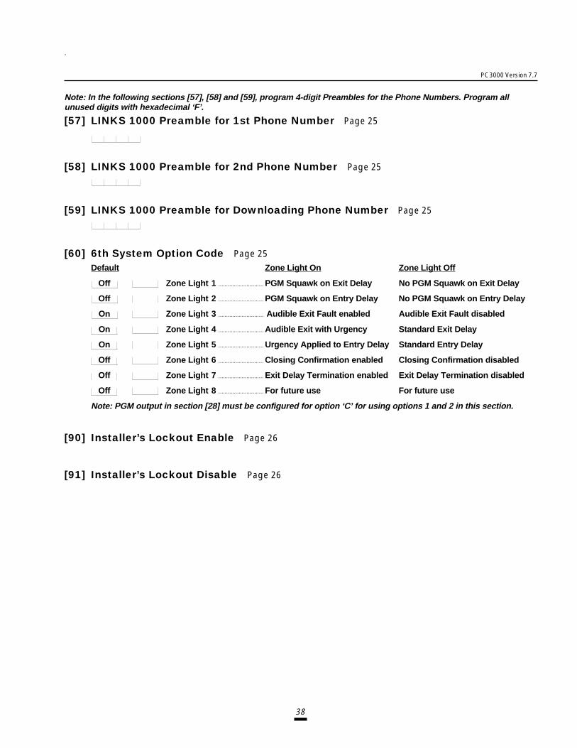
38
PC3000 Version 7.7
Note: In the following sections [57], [58] and [59], program 4-digit Preambles for the Phone Numbers. Program allunused digits with hexadecimal ‘F’.
[57] LINKS 1000 Preamble for 1st Phone Number Page 25
[58] LINKS 1000 Preamble for 2nd Phone Number Page 25
[59] LINKS 1000 Preamble for Downloading Phone Number Page 25
[60] 6th System Option Code Page 25Default Zone Light On Zone Light Off
Off Zone Light 1 ............................. PGM Squawk on Exit Delay No PGM Squawk on Exit Delay
Off Zone Light 2 ............................. PGM Squawk on Entry Delay No PGM Squawk on Entry Delay
On Zone Light 3 ............................. Audible Exit Fault enabled Audible Exit Fault disabled
On Zone Light 4 ............................. Audible Exit with Urgency Standard Exit Delay
On Zone Light 5 ............................. Urgency Applied to Entry Delay Standard Entry Delay
Off Zone Light 6 ............................. Closing Confirmation enabled Closing Confirmation disabled
Off Zone Light 7 ............................. Exit Delay Termination enabled Exit Delay Termination disabled
Off Zone Light 8 ............................. For future use For future use
Note: PGM output in section [28] must be configured for option ‘C’ for using options 1 and 2 in this section.
[90] Installer’s Lockout Enable Page 26
[91] Installer’s Lockout Disable Page 26

39
NC
NO
Z15
CO
M
Z16
Z15
CO
M
Z16
Refer toinstructions onkeypad wiring.
Battery 12V/4.0AhGELL-CELL max
battery chargecurrent is 360 mA.Battery capacity for
emergency is atleast 4 hours.
Bell\Siren700 mA max
50 mA max
+12V
-AUX
+12VSwitched
PC3000RK Keypad(3 Max)
End of line resistor1KΩ 1/2 Watt
Typical Burglary Zone ConnectionNormallyclosed
contacts
Normallyopen
contacts
AuxiliarySupply
Outputs400 mA max
Nut
Washer
Cabinet
Bolt
Ground Rod
NC NO
YEL GRN
BLK REDWHT
PGM Output Relay(Keypad [],[7])
COM
PGM AUX
Ground Start Circuit
RM-1
BLK REDWHT
PGM AUX
RNG
GRN
RM-1
NO AUX
+ RED
- BLK
BRN
GRY
GRN
RED
AC
4-Wire smokepower 12 VDC400mA max
Alarm initiating loopResistance 100Ω max
RED
BLK
WHT
GRN
In Out
In Out
ULC listed4-wire smoke detector End-of-line resistor
1kΩ 1/2 Watt
AUXGNDSWAUX
+ -BELL
Typical Fire Alarm Zone Connections
NOTE: Smoke detector must be 4-wire ULC listed latchingtype (ESL 446C).To reset smoke detectors - press [] then hold down key[4] for 2-3 seconds.
Bell loop700 mA max
HornFIRE
Smoke detector powersupervision relay (DSC RM-1)12VDC 35mA
AlarmContact
Temperature Range: 0°C-49°C (32°F-120°F)Maximum Humidity: 85% R.H.
Aux
1A
Bell
5A
Batt
5A
AC Power
CSA Listed16VAC 40VA
AUX GNDSWAUX RED BLK YEL GRN FIREPGM
OUTAUXIN Z1 COM Z2 Z3 COM Z4 Z5 COM Z6 Z7 COM Z8 Z9 COM Z10 Z11 COM Z12 COMZ13 Z14 COMZ15 Z16KEYPAD+ -
BELL
T1
R1
TIP
RNG
RE
D
BLK
YE
L
GR
N
HOOKUP DIAGRAMS
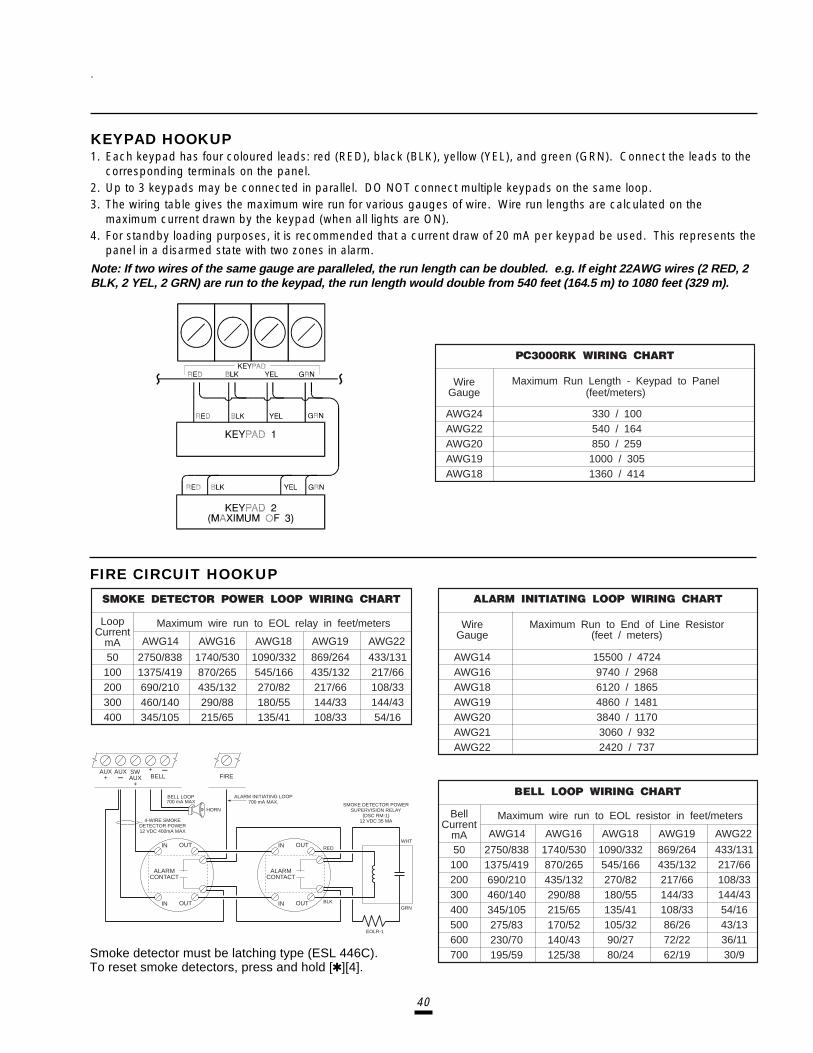
40
KEYPAD HOOKUP1. Each keypad has four coloured leads: red (RED), black (BLK), yellow (YEL), and green (GRN). Connect the leads to the
corresponding terminals on the panel.2. Up to 3 keypads may be connected in parallel. DO NOT connect multiple keypads on the same loop.3. The wiring table gives the maximum wire run for various gauges of wire. Wire run lengths are calculated on the
maximum current drawn by the keypad (when all lights are ON).4. For standby loading purposes, it is recommended that a current draw of 20 mA per keypad be used. This represents the
panel in a disarmed state with two zones in alarm.
Note: If two wires of the same gauge are paralleled, the run length can be doubled. e.g. If eight 22AWG wires (2 RED, 2BLK, 2 YEL, 2 GRN) are run to the keypad, the run length would double from 540 feet (164.5 m) to 1080 feet (329 m).
FIRE CIRCUIT HOOKUP
LoopCurrent
mA50 2750/838
1375/419690/210460/140345/105
1740/530870/265435/132290/88215/65
1090/332545/166270/82180/55135/41
869/264435/132217/66144/33108/33
433/131217/66108/33144/4354/16
100200300400
Maximum wire run to EOL relay in feet/meters
AWG14 AWG16 AWG18 AWG19 AWG22
AWG14 15500 / 47249740 / 29686120 / 18654860 / 14813840 / 11703060 / 9322420 / 737
AWG16AWG18AWG19AWG20AWG21AWG22
WireGauge
Maximum Run to End of Line Resistor(feet / meters)
BellCurrent
mA50 2750/838
1375/419690/210460/140345/105275/83230/70195/59
1740/530870/265435/132290/88215/65170/52140/43125/38
1090/332545/166270/82180/55135/41105/3290/2780/24
869/264435/132217/66144/33108/3386/2672/2262/19
433/131217/66108/33144/4354/1643/1336/1130/9
100200300400500600700
Maximum wire run to EOL resistor in feet/meters
AWG14 AWG16 AWG18 AWG19 AWG22
WireGauge
AWG24 330 / 100540 / 164850 / 2591000 / 3051360 / 414
AWG22AWG20AWG19AWG18
Maximum Run Length - Keypad to Panel(feet/meters)
Smoke detector must be latching type (ESL 446C).To reset smoke detectors, press and hold [Q][4].
ALARMCONTACT
IN
IN
OUT
OUT
ALARMCONTACT
IN
IN
OUT
OUT
AUX+
AUX SWAUX
+BELL FIRE
+
HORN
ALARM INITIATING LOOP700 mA MAX.
BELL LOOP700 mA MAX
4-WIRE SMOKEDETECTOR POWER12 VDC 400mA MAX
REDWHT
SMOKE DETECTOR POWERSUPERVISION RELAY
(DSC RM-1)12 VDC 35 MA
BLKGRN
EOLR-1
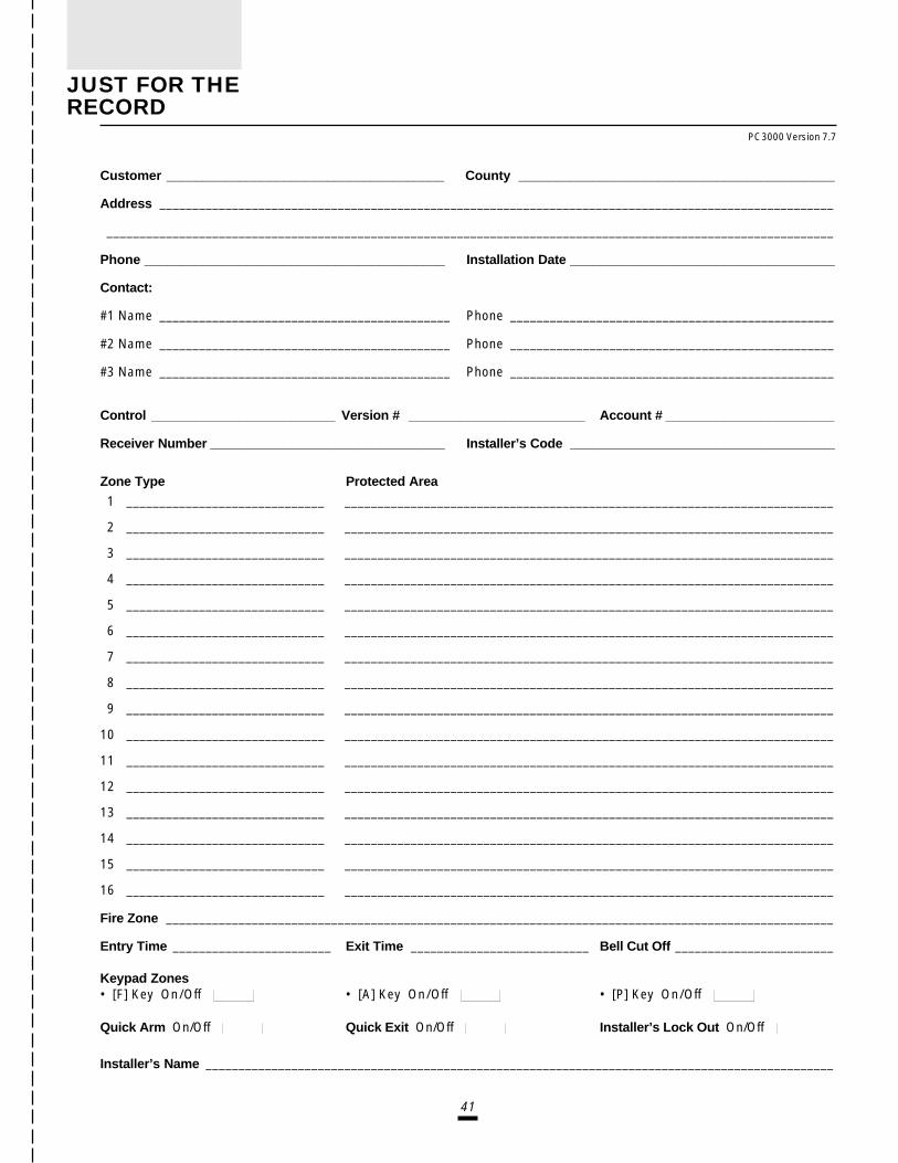
41
Customer ______________________________________ County ___________________________________________
Address ______________________________________________________________________________________________________
______________________________________________________________________________________________________________
Phone _________________________________________ Installation Date ____________________________________
Contact:
#1 Name ____________________________________________ Phone _________________________________________________
#2 Name ____________________________________________ Phone _________________________________________________
#3 Name ____________________________________________ Phone _________________________________________________
Control _________________________ Version # ________________________ Account # _______________________
Receiver Number ________________________________ Installer’s Code ____________________________________
Zone Type Protected Area
1 ______________________________ __________________________________________________________________________
2 ______________________________ __________________________________________________________________________
3 ______________________________ __________________________________________________________________________
4 ______________________________ __________________________________________________________________________
5 ______________________________ __________________________________________________________________________
6 ______________________________ __________________________________________________________________________
7 ______________________________ __________________________________________________________________________
8 ______________________________ __________________________________________________________________________
9 ______________________________ __________________________________________________________________________
10 ______________________________ __________________________________________________________________________
11 ______________________________ __________________________________________________________________________
12 ______________________________ __________________________________________________________________________
13 ______________________________ __________________________________________________________________________
14 ______________________________ __________________________________________________________________________
15 ______________________________ __________________________________________________________________________
16 ______________________________ __________________________________________________________________________
Fire Zone _____________________________________________________________________________________________________
Entry Time ________________________ Exit Time ___________________________ Bell Cut Off ________________________
Keypad Zones• [F] Key On/Off • [A] Key On/Off • [P] Key On/Off
Quick Arm On/Off Quick Exit On/Off Installer’s Lock Out On/Off
Installer’s Name _______________________________________________________________________________________________
PC3000 Version 7.7
JUST FOR THERECORD

42
Notes:

© 1996 Digital Security Controls Ltd.1645 Flint Rd., Downsview, Ontario Canada M3J 2J6Tel: (416) 665-8460 • Fax: (416) 665-7498 • Tech. Line 1-800-387-3630

29000601 R2
PC3000Notice of Software Release
PC3000 software version 7.7 has now been released.Several new features have been added to reduce the possibility of user caused falsealarms. And also, additional features have been added to provide further support for theLINKS 1000 and Escort.These changes are outlined in the following programming sections.[22] System Times Page 18
System Times now allow more than 4 minutes of Entry or Exit Delay. It providesusers additional time when circumstances warrant. The default setting of Exit Delayis 120 seconds.
[28] Programmable Input and Output Options Page 202nd Digit Programmable Output
[C] PGM Squawk Output (for use with options in section [60]).
[49] 4th System Option Code Page 23• Fire Zone on Switched Aux Supply
- Prevents Fire Alarm Circuit Troubles if [Q][4] is used to reset sensors.• Escort Accepts Master Code Only
- Remote access through the Escort requires the Master Code.
[57] LINKS 1000 Preamble for 1st Telephone Number Page 24
[58] LINKS 1000 Preamble for 2nd Telephone Number Page 24
[59] LINKS 1000 Preamble for Downloading Telephone Number Page 24The LINKS 1000 preambles are 4 digit numbers which are used for programmingarea codes in cases where the LINKS 1000 must call long distance.
[60] 6th System Option Code Page 25• PGM Squawk on Exit Delay - The PGM Output will squawk for the Exit Delay.• PGM Squawk on Entry Delay - The PGM Output will squawk for the Entry Delay.• Audible Exit Fault - The user is warned that a delay zone was left open when the
exit delay expired.• Audible Exit Delay with Urgency - The keypad sounds a pulsing tone for the exit
delay and sounds a faster pulsing tone for the last 10 seconds.• Urgency on Entry Delay - The keypad pulses the steady entry delay tone for the
last 10 seconds.• Closing Confirmation - The keypad will sound a short series of beeps when the
closing code has been successfully transmitted.• Exit Delay Termination - The exit delay is cancelled when a standard delay zone
is restored.
NOTE: Downloading Software DLS-1 Version 5.3 must be used to upload/download the new PC3000v7.7 software. Do not attempt to upload/download with the DLS-1 Version 5.2 or earlier software.

InstallationManual
PC3OOO Control PanelSoftware Version 7.7
SEE BACK COVER FOR
SEE BACK COVER FOR
SEE BACK COVER FOR
SEE BACK COVER FOR
SEE BACK COVER FOR
NEW FEA
NEW FEA
NEW FEA
NEW FEA
NEW FEATURES OF V7.7
TURES OF V7.7
TURES OF V7.7
TURES OF V7.7
TURES OF V7.7

AVIS: Létiquette de lIndustrie Canada identifie le matériel homologué. Cette étiquette certifie que le matériel est conforme à certaines normesde protection, dexploitation et de sécurité des réseaux de télécommunications. Industrie Canada nassure toutefois pas que le matérielfonctionnera à la satisfaction de lutilisateur.
Avant dinstaller ce matériel, lutilisateur doit sassurer quil est permis de le raccorder aux installations de lentreprise locale detélécommunication. Le matériel doit également être installé en suivant une méthode acceptée de raccordement. Labonné ne doit pas oublierquil est possible que la conformité aux conditions énoncées ci-dessus nempêchent pas la dégradation du service dans certaines situations.
Les réparations de matériel homologué doivent être effectuées par un centre dentretien canadien autorisé désigné par le fournisseur. Lacompagnie de télécommunications peut demander à lutilisateur de débrancher un appareil à la suite de réparations ou de modificationseffectuées par lutilisateur ou à cause de mauvais fonctionnement.
Pour sa propre protection, lutilisateur doit sassurer que tous les fils de mise à la terre de la source dénergie électrique, les lignes téléphoniqueset les canalisations deau métalliques, sil y en a, sont raccordés ensemble. Cette précaution est particulièrement importante dans les régionsrurales.
AVERTISSEMENT: Lutilisateur ne doit pas tenter de faire ces raccordements lui-même; il doit avoir recours à un service dinspection desinstallations électriques, ou à un électricien, selon le cas.
Lindice de charge (IC) assigné a chaque dispositif terminal indique, pour éviter toute surcharge, le pourcentage de la charge totale qui peutêtre raccordée à un circuit téléphonique bouclé utilisé par ce dispositif. La terminaison du circuit bouclé peut être constituée de nimporte quellecombinaison de dispositifs, pourvu que la somme des indices de charge de lensemble des dispositifs ne dépasse pas 100.
LIndice de charge de ce produit est 42.
NOTICE: The Industry Canada label identifies certified equipment. This certification means that the equipment meets certain telecommunicationsnetwork protective, operational and safety requirements. Industry Canada does not guarantee the equipment will operate to the userssatisfaction.
Before installing this equipment, users should ensure that it is permissible to be connected to the facilities of the local telecommunicationscompany. The equipment must also be installed using an acceptable method of connection. The customer should be aware that compliance withthe above conditions may not prevent degradation of service in some situations.
Repairs to certified equipment should be made by an authorized Canadian maintenance facility designated by the supplier. Any repairs oralterations made by the user to this equipment, or equipment malfunctions, may give the telecommunications company cause to request the userto disconnect the equipment.
User should ensure for their own protection that the electrical ground connections of the power utility, telephone lines and internal metallicwater pipe system, if present, are connected together. This precaution may be particularly important in rural areas.
CAUTION: Users should not attempt to make such connections themselves, but should contact the appropriate electric inspection authority,or electrician, as appropriate.
The Load Number (LN) assigned to each terminal device denotes the percentage of the total load to be connected to a telephone loop whichis used by the device, to prevent overloading. The termination on a loop may consist of any combination of devices subject only to therequirement that the total of the Load Numbers of all the devices does not exceed 100.
The Load Number of this unit is 42.
Limited WarrantyDigital Security Controls Ltd. warrants that for a period of twelve months from the date of purchase, the product shall be free ofdefects in materials and workmanship under normal use and that in fulfilment of any breach of such warranty, Digital SecurityControls Ltd. shall, at its option, repair or replace the defective equipment upon return of the equipment to its repair depot. Thiswarranty applies only to defects in parts and workmanship and not to damage incurred in shipping or handling, or damage due tocauses beyond the control of Digital Security Controls Ltd. such as lightning, excessive voltage, mechanical shock, waterdamage, or damage arising out of abuse, alteration or improper application of the equipment.The foregoing warranty shall apply only to the original buyer, and is and shall be in lieu of any and all other warranties, whetherexpressed or implied and of all other obligations or liabilities on the part of Digital Security Controls Ltd. This warranty contains theentire warranty. Digital Security Controls Ltd. neither assumes, nor authorizes any other person purporting to act on its behalf tomodify or to change this warranty, nor to assume for it any other warranty or liability concerning this product.
In no event shall Digital Security Controls Ltd. be liable for any direct, indirect or consequential damages, loss of anticipatedprofits, loss of time or any other losses incurred by the buyer in connection with the purchase, installation or operation or failure ofthis product.
Warning: Digital Security Controls Ltd. recommends that the entire system be completely tested on a regular basis.However, despite frequent testing, and due to, but not limited to, criminal tampering or electrical disruption, it is possiblefor this product to fail to perform as expected.

TABLE OF CONTENTS
PageLimited Warranty
Specifications ____________________________________________________________ 1
Features ___________________________________________________________________ 2
Installation ________________________________________________________________ 3
Bench Testing ______________________________________________________________ 3Mounting Panel _____________________________________________________________ 3Hook-up Procedure __________________________________________________________ 3Terminal Connections________________________________________________________ 4
Guidelines for Smoke Detector Location ___________________________ 6
Keypad Functions _______________________________________________________ 7
Introduction ________________________________________________________________ 7Master Code ________________________________________________________________ 7Installer’s Programming Code ________________________________________________ 7Arming _____________________________________________________________________ 7Disarming __________________________________________________________________ 7Auto-Bypass/Home-Away Arming _____________________________________________ 7Zone Bypassing ___________________ [Q]+[1] or [Q]+[1]+[Access Code] _________ 7Trouble Display ___________________ [Q]+[2] _________________________________ 8Alarm Memory Display _____________ [Q]+[3] _________________________________ 8Switched Auxiliary Supply Control ___ [Q]+[Hold Down 4] _______________________ 8User’s Programming Commands ____ [Q]+[5]+[Master Code] ___________________ 9User’s Functions Command ________ [Q]+[6]+[Master Code] ___________________ 9Installer’s Test ____________________ [Q]+[6]+[Master Code]+[0] ______________ 10Setting the Clock __________________ [Q]+[6]+[Master Code]+[1] ______________ 10Auto-arm Time of Day ______________ [Q]+[6]+[Master Code]+[2] ______________ 10Quick Arm ________________________ [Q]+[6]+[Master Code]+[4] ______________ 10Auto-arm Enable __________________ [Q]+[6]+[Master Code]+[5] ______________ 10Door Chime_______________________ [Q]+[6]+[Master Code]+[6] ______________ 10System Test ______________________ [Q]+[6]+[Master Code]+[8] ______________ 10User Callup _______________________ [Q]+[6]+[Master Code]+[9] ______________ 10Utility Output Command ____________ [Q]+[7] or [Q]+[7]+[Access Code] ________ 11Installer’s Programming Commands _ [Q]+[8]+[Installer’s Code] ________________ 11“At Home” Arming _________________ [Q]+[9]+[Access Code] __________________ 11“Quick Arm” Command ____________ [Q]+[0] ________________________________ 11Quick Exit ________________________ [Q]+[0] when armed _____________________ 11Keypad Zones _____________________________________________________________ 11
Downloading _____________________________________________________________ 12
Programming Guide ____________________________________________________ 13
Introduction _______________________________________________________________ 13Reviewing Programmed Data ________________________________________________ 13[00] Binary Programming ____________________________________________________ 13[01] 1st Phone Number _____________________________________________________ 14[02] 1st Account Code ______________________________________________________ 14[03] 2nd Phone Number_____________________________________________________ 14[04] 2nd Account Code _____________________________________________________ 14[05]...[15] Reporting Codes Explanation ______________________________________ 14
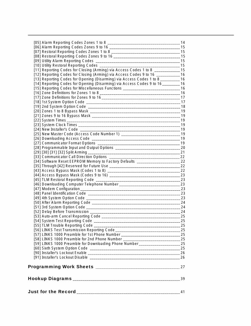
[05] Alarm Reporting Codes Zones 1 to 8 _____________________________________ 14[06] Alarm Reporting Codes Zones 9 to 16 ____________________________________ 15[07] Restoral Reporting Codes Zones 1 to 8 ___________________________________ 15[08] Restoral Reporting Codes Zones 9 to 16 __________________________________ 15[09] Utility Alarm Reporting Codes ___________________________________________ 15[10] Utility Restoral Reporting Codes _________________________________________ 15[11] Reporting Codes for Closing (Arming) via Access Codes 1 to 8 _____________ 15[12] Reporting Codes for Closing (Arming) via Access Codes 9 to 16 ____________ 16[13] Reporting Codes for Opening (Disarming) via Access Codes 1 to 8 __________ 16[14] Reporting Codes for Opening (Disarming) via Access Codes 9 to 16_________ 16[15] Reporting Codes for Miscellaneous Functions _____________________________ 16[16] Zone Definitions for Zones 1 to 8 _________________________________________ 16[17] Zone Definitions for Zones 9 to 16 ________________________________________ 17[18] 1st System Option Code ________________________________________________ 17[19] 2nd System Option Code _______________________________________________ 18[20] Zones 1 to 8 Bypass Mask ______________________________________________ 19[21] Zones 9 to 16 Bypass Mask _____________________________________________ 19[22] System Times __________________________________________________________ 19[23] System Clock Times ____________________________________________________ 19[24] New Installer’s Code ___________________________________________________ 19[25] New Master Code (Access Code Number 1) ______________________________ 19[26] Downloading Access Code _____________________________________________ 19[27] Communicator Format Options __________________________________________ 19[28] Programmable Input and Output Options _________________________________ 20[29] [30] [31] [32] Split Arming _______________________________________________ 21[33] Communicator Call Direction Options ____________________________________ 22[34] Software Reset EEPROM Memory to Factory Defaults ______________________ 22[35] Through [42] Reserved for Future Use ____________________________________ 22[43] Access Bypass Mask (Codes 1 to 8) _____________________________________ 22[44] Access Bypass Mask (Codes 9 to 16) ____________________________________ 23[45] TLM Restoral Reporting Code ___________________________________________ 23[46] Downloading Computer Telephone Number _______________________________ 23[47] Modem Configuration ___________________________________________________ 23[48] Panel Identification Code _______________________________________________ 23[49] 4th System Option Code ________________________________________________ 23[50] After Alarm Reporting Code _____________________________________________ 24[51] 3rd System Option Code ________________________________________________ 24[52] Delay Before Transmission ______________________________________________ 24[53] Auto-arm Cancel Reporting Code ________________________________________ 25[54] System Test Reporting Code ____________________________________________ 25[55] TLM Trouble Reporting Code ____________________________________________ 25[56] LINKS Test Transmission Reporting Code _________________________________ 25[57] LINKS 1000 Preamble for 1st Phone Number ______________________________ 25[58] LINKS 1000 Preamble for 2nd Phone Number _____________________________ 25[59] LINKS 1000 Preamble for Downloading Phone Number_____________________ 25[60] Sixth System Option Code ______________________________________________ 25[90] Installer’s Lockout Enable _______________________________________________ 26[91] Installer’s Lockout Disable ______________________________________________ 26
Programming Work Sheets _____________________________________ 27
Hookup Diagrams _______________________________________________________ 39
Just for the Record _____________________________________________________ 41
Related Documents