D R ibm.com/redbooks Front cover DS4000 Best Practices and Performance Tuning Guide Bertrand Dufrasne Michele Lunardon Al Watson Brian Youngs DS4000 concepts and planning: performance tuning Performance measurement tools Implementation quick guide

Welcome message from author
This document is posted to help you gain knowledge. Please leave a comment to let me know what you think about it! Share it to your friends and learn new things together.
Transcript

D R
ibm.com/redbooks
Front cover
DS4000 Best Practices and Performance Tuning Guide
Bertrand DufrasneMichele Lunardon
Al WatsonBrian Youngs
DS4000 concepts and planning: performance tuning
Performance measurement tools
Implementation quick guide


International Technical Support Organization
DS4000 Best Practices and Performance Tuning Guide
January 2006
SG24-6363-01
© Copyright International Business Machines Corporation 2005, 2006. All rights reserved.Note to U.S. Government Users Restricted Rights -- Use, duplication or disclosure restricted by GSA ADP ScheduleContract with IBM Corp.
Second Edition (January 2006)
This edition applies to IBM TotalStorage DS4000 Storage Servers and related products that were current as of November 2005.
Note: Before using this information and the product it supports, read the information in “Notices” on page vii.

Contents
Notices . . . . . . . . . . . . . . . . . . . . . . . . . . . . . . . . . . . . . . . . . . . . . . . . . . . . . . . . . . . . . . . . . viiTrademarks . . . . . . . . . . . . . . . . . . . . . . . . . . . . . . . . . . . . . . . . . . . . . . . . . . . . . . . . . . . . . viii
Preface . . . . . . . . . . . . . . . . . . . . . . . . . . . . . . . . . . . . . . . . . . . . . . . . . . . . . . . . . . . . . . . . . ixThe team that wrote this redbook. . . . . . . . . . . . . . . . . . . . . . . . . . . . . . . . . . . . . . . . . . . . . . ixBecome a published author . . . . . . . . . . . . . . . . . . . . . . . . . . . . . . . . . . . . . . . . . . . . . . . . . . xiComments welcome. . . . . . . . . . . . . . . . . . . . . . . . . . . . . . . . . . . . . . . . . . . . . . . . . . . . . . . . xii
Summary of changes . . . . . . . . . . . . . . . . . . . . . . . . . . . . . . . . . . . . . . . . . . . . . . . . . . . . . xiiiJanuary 2006, Second Edition . . . . . . . . . . . . . . . . . . . . . . . . . . . . . . . . . . . . . . . . . . . . . . . xiii
Chapter 1. Introduction to DS4000 and SAN . . . . . . . . . . . . . . . . . . . . . . . . . . . . . . . . . . 11.1 DS4000 features and models . . . . . . . . . . . . . . . . . . . . . . . . . . . . . . . . . . . . . . . . . . . . . 2
1.1.1 DS4000 Series product comparison . . . . . . . . . . . . . . . . . . . . . . . . . . . . . . . . . . . . 41.2 DS4000 Storage Manager . . . . . . . . . . . . . . . . . . . . . . . . . . . . . . . . . . . . . . . . . . . . . . . 61.3 Introduction to SAN . . . . . . . . . . . . . . . . . . . . . . . . . . . . . . . . . . . . . . . . . . . . . . . . . . . . . 7
1.3.1 SAN components . . . . . . . . . . . . . . . . . . . . . . . . . . . . . . . . . . . . . . . . . . . . . . . . . . 81.3.2 SAN zoning . . . . . . . . . . . . . . . . . . . . . . . . . . . . . . . . . . . . . . . . . . . . . . . . . . . . . . 10
Chapter 2. DS4000 planning tasks . . . . . . . . . . . . . . . . . . . . . . . . . . . . . . . . . . . . . . . . . 132.1 Planning your SAN and Storage Server . . . . . . . . . . . . . . . . . . . . . . . . . . . . . . . . . . . . 14
2.1.1 SAN zoning for DS4000 . . . . . . . . . . . . . . . . . . . . . . . . . . . . . . . . . . . . . . . . . . . . 152.2 Physical components planning . . . . . . . . . . . . . . . . . . . . . . . . . . . . . . . . . . . . . . . . . . . 16
2.2.1 Rack considerations . . . . . . . . . . . . . . . . . . . . . . . . . . . . . . . . . . . . . . . . . . . . . . . 162.2.2 Cables and connectors . . . . . . . . . . . . . . . . . . . . . . . . . . . . . . . . . . . . . . . . . . . . . 182.2.3 Cable management and labeling . . . . . . . . . . . . . . . . . . . . . . . . . . . . . . . . . . . . . 212.2.4 Fibre Channel adapters . . . . . . . . . . . . . . . . . . . . . . . . . . . . . . . . . . . . . . . . . . . . 232.2.5 Disk expansion enclosures . . . . . . . . . . . . . . . . . . . . . . . . . . . . . . . . . . . . . . . . . . 252.2.6 Selecting drives. . . . . . . . . . . . . . . . . . . . . . . . . . . . . . . . . . . . . . . . . . . . . . . . . . . 27
2.3 Planning your storage structure . . . . . . . . . . . . . . . . . . . . . . . . . . . . . . . . . . . . . . . . . . 292.3.1 Arrays and RAID levels . . . . . . . . . . . . . . . . . . . . . . . . . . . . . . . . . . . . . . . . . . . . . 292.3.2 Logical drives and controller ownership . . . . . . . . . . . . . . . . . . . . . . . . . . . . . . . . 372.3.3 Hot spare drive . . . . . . . . . . . . . . . . . . . . . . . . . . . . . . . . . . . . . . . . . . . . . . . . . . . 402.3.4 Storage partitioning. . . . . . . . . . . . . . . . . . . . . . . . . . . . . . . . . . . . . . . . . . . . . . . . 412.3.5 Media scan . . . . . . . . . . . . . . . . . . . . . . . . . . . . . . . . . . . . . . . . . . . . . . . . . . . . . . 442.3.6 Segment size . . . . . . . . . . . . . . . . . . . . . . . . . . . . . . . . . . . . . . . . . . . . . . . . . . . . 452.3.7 Cache parameters . . . . . . . . . . . . . . . . . . . . . . . . . . . . . . . . . . . . . . . . . . . . . . . . 45
2.4 Planning for premium features . . . . . . . . . . . . . . . . . . . . . . . . . . . . . . . . . . . . . . . . . . . 502.4.1 FlashCopy. . . . . . . . . . . . . . . . . . . . . . . . . . . . . . . . . . . . . . . . . . . . . . . . . . . . . . . 502.4.2 VolumeCopy . . . . . . . . . . . . . . . . . . . . . . . . . . . . . . . . . . . . . . . . . . . . . . . . . . . . . 502.4.3 Enhanced Remote Mirroring (ERM) . . . . . . . . . . . . . . . . . . . . . . . . . . . . . . . . . . . 512.4.4 FC/SATA Intermix . . . . . . . . . . . . . . . . . . . . . . . . . . . . . . . . . . . . . . . . . . . . . . . . . 52
2.5 Additional planning considerations . . . . . . . . . . . . . . . . . . . . . . . . . . . . . . . . . . . . . . . . 532.5.1 Planning for systems with LVM: AIX example. . . . . . . . . . . . . . . . . . . . . . . . . . . . 532.5.2 Planning for systems without LVM: Windows example. . . . . . . . . . . . . . . . . . . . . 562.5.3 The function of ADT and a multipath driver. . . . . . . . . . . . . . . . . . . . . . . . . . . . . . 58
Chapter 3. DS4000 configuration tasks . . . . . . . . . . . . . . . . . . . . . . . . . . . . . . . . . . . . . 613.1 Preparing the DS4000 Storage Server . . . . . . . . . . . . . . . . . . . . . . . . . . . . . . . . . . . . . 62
© Copyright IBM Corp. 2005, 2006. All rights reserved. iii
3.1.1 Initial setup of the DS4000 Storage Server. . . . . . . . . . . . . . . . . . . . . . . . . . . . . . 623.1.2 Installing and starting the D4000 Storage Manager Client . . . . . . . . . . . . . . . . . . 66
3.2 DS4000 cabling. . . . . . . . . . . . . . . . . . . . . . . . . . . . . . . . . . . . . . . . . . . . . . . . . . . . . . . 703.2.1 DS4100 and DS4300 host cabling configuration . . . . . . . . . . . . . . . . . . . . . . . . . 703.2.2 DS4100 and DS4300 drive expansion cabling . . . . . . . . . . . . . . . . . . . . . . . . . . . 723.2.3 DS4400 and DS4500 host cabling configuration . . . . . . . . . . . . . . . . . . . . . . . . . 723.2.4 DS4400 and DS4500 drive expansion cabling . . . . . . . . . . . . . . . . . . . . . . . . . . . 743.2.5 DS4800 host cabling configuration . . . . . . . . . . . . . . . . . . . . . . . . . . . . . . . . . . . . 773.2.6 DS4800 drive expansion cabling . . . . . . . . . . . . . . . . . . . . . . . . . . . . . . . . . . . . . 783.2.7 Expansion enclosures. . . . . . . . . . . . . . . . . . . . . . . . . . . . . . . . . . . . . . . . . . . . . . 80
3.3 Configuring the DS4000 Storage Server. . . . . . . . . . . . . . . . . . . . . . . . . . . . . . . . . . . . 833.3.1 Defining hot-spare drives . . . . . . . . . . . . . . . . . . . . . . . . . . . . . . . . . . . . . . . . . . . 843.3.2 Creating arrays and logical drives. . . . . . . . . . . . . . . . . . . . . . . . . . . . . . . . . . . . . 853.3.3 Configuring storage partitioning . . . . . . . . . . . . . . . . . . . . . . . . . . . . . . . . . . . . . . 893.3.4 Configuring for Copy Services functions. . . . . . . . . . . . . . . . . . . . . . . . . . . . . . . . 91
3.4 Additional DS4000 configuration tasks . . . . . . . . . . . . . . . . . . . . . . . . . . . . . . . . . . . . . 923.4.1 DS4000 Storage Server rename and synchronizing the controller clock . . . . . . . 923.4.2 Saving the subsystem profile . . . . . . . . . . . . . . . . . . . . . . . . . . . . . . . . . . . . . . . . 93
3.5 Event monitoring and alerts . . . . . . . . . . . . . . . . . . . . . . . . . . . . . . . . . . . . . . . . . . . . . 933.5.1 ADT alert notification. . . . . . . . . . . . . . . . . . . . . . . . . . . . . . . . . . . . . . . . . . . . . . . 943.5.2 Failover alert delay . . . . . . . . . . . . . . . . . . . . . . . . . . . . . . . . . . . . . . . . . . . . . . . . 953.5.3 DS4000 Service Alert . . . . . . . . . . . . . . . . . . . . . . . . . . . . . . . . . . . . . . . . . . . . . . 963.5.4 Alert Manager Services. . . . . . . . . . . . . . . . . . . . . . . . . . . . . . . . . . . . . . . . . . . . . 99
3.6 Software and microcode upgrades . . . . . . . . . . . . . . . . . . . . . . . . . . . . . . . . . . . . . . . 1013.6.1 Staying up-to-date with your drivers and firmware using My support . . . . . . . . . 1013.6.2 Prerequisites for upgrades . . . . . . . . . . . . . . . . . . . . . . . . . . . . . . . . . . . . . . . . . 1023.6.3 Updating the controller microcode . . . . . . . . . . . . . . . . . . . . . . . . . . . . . . . . . . . 1023.6.4 Updating DS4000 host software . . . . . . . . . . . . . . . . . . . . . . . . . . . . . . . . . . . . . 107
3.7 Capacity upgrades, system upgrades. . . . . . . . . . . . . . . . . . . . . . . . . . . . . . . . . . . . . 1083.7.1 Capacity upgrades and increased bandwidth . . . . . . . . . . . . . . . . . . . . . . . . . . . 1083.7.2 Storage server upgrade and disk migration procedures . . . . . . . . . . . . . . . . . . . 109
Chapter 4. DS4000 performance tuning . . . . . . . . . . . . . . . . . . . . . . . . . . . . . . . . . . . . 1134.1 Workload types . . . . . . . . . . . . . . . . . . . . . . . . . . . . . . . . . . . . . . . . . . . . . . . . . . . . . . 1144.2 Solution wide considerations for performance . . . . . . . . . . . . . . . . . . . . . . . . . . . . . . 1154.3 Host considerations. . . . . . . . . . . . . . . . . . . . . . . . . . . . . . . . . . . . . . . . . . . . . . . . . . . 116
4.3.1 Host based settings . . . . . . . . . . . . . . . . . . . . . . . . . . . . . . . . . . . . . . . . . . . . . . 1164.3.2 Host setting examples. . . . . . . . . . . . . . . . . . . . . . . . . . . . . . . . . . . . . . . . . . . . . 118
4.4 Application considerations . . . . . . . . . . . . . . . . . . . . . . . . . . . . . . . . . . . . . . . . . . . . . 1264.4.1 Application examples . . . . . . . . . . . . . . . . . . . . . . . . . . . . . . . . . . . . . . . . . . . . . 127
4.5 DS4000 Storage Server considerations . . . . . . . . . . . . . . . . . . . . . . . . . . . . . . . . . . . 1284.5.1 Which model fits best . . . . . . . . . . . . . . . . . . . . . . . . . . . . . . . . . . . . . . . . . . . . . 1284.5.2 Storage Server processes . . . . . . . . . . . . . . . . . . . . . . . . . . . . . . . . . . . . . . . . . 1304.5.3 Storage Server modification functions . . . . . . . . . . . . . . . . . . . . . . . . . . . . . . . . 1324.5.4 Storage Server parameters. . . . . . . . . . . . . . . . . . . . . . . . . . . . . . . . . . . . . . . . . 1344.5.5 Disk drive types. . . . . . . . . . . . . . . . . . . . . . . . . . . . . . . . . . . . . . . . . . . . . . . . . . 1354.5.6 Arrays and logical drives. . . . . . . . . . . . . . . . . . . . . . . . . . . . . . . . . . . . . . . . . . . 1364.5.7 Additional NVSRAM parameters of concern. . . . . . . . . . . . . . . . . . . . . . . . . . . . 141
4.6 Fabric considerations . . . . . . . . . . . . . . . . . . . . . . . . . . . . . . . . . . . . . . . . . . . . . . . . . 141
Chapter 5. DS4000 tuning with typical application examples. . . . . . . . . . . . . . . . . . . 1435.1 DB2 database . . . . . . . . . . . . . . . . . . . . . . . . . . . . . . . . . . . . . . . . . . . . . . . . . . . . . . . 144
5.1.1 Data location . . . . . . . . . . . . . . . . . . . . . . . . . . . . . . . . . . . . . . . . . . . . . . . . . . . . 144
iv DS4000 Best Practices and Performance Tuning Guide
5.1.2 Database structure . . . . . . . . . . . . . . . . . . . . . . . . . . . . . . . . . . . . . . . . . . . . . . . 1445.1.3 Database RAID type . . . . . . . . . . . . . . . . . . . . . . . . . . . . . . . . . . . . . . . . . . . . . . 1465.1.4 DB2 logs and archives . . . . . . . . . . . . . . . . . . . . . . . . . . . . . . . . . . . . . . . . . . . . 147
5.2 Oracle databases . . . . . . . . . . . . . . . . . . . . . . . . . . . . . . . . . . . . . . . . . . . . . . . . . . . . 1475.2.1 Data location . . . . . . . . . . . . . . . . . . . . . . . . . . . . . . . . . . . . . . . . . . . . . . . . . . . . 1475.2.2 Database RAID type . . . . . . . . . . . . . . . . . . . . . . . . . . . . . . . . . . . . . . . . . . . . . . 1485.2.3 Redo logs RAID type . . . . . . . . . . . . . . . . . . . . . . . . . . . . . . . . . . . . . . . . . . . . . 1485.2.4 Volume management . . . . . . . . . . . . . . . . . . . . . . . . . . . . . . . . . . . . . . . . . . . . . 148
5.3 Microsoft SQL Server . . . . . . . . . . . . . . . . . . . . . . . . . . . . . . . . . . . . . . . . . . . . . . . . . 1495.3.1 Allocation unit size . . . . . . . . . . . . . . . . . . . . . . . . . . . . . . . . . . . . . . . . . . . . . . . 1495.3.2 RAID levels . . . . . . . . . . . . . . . . . . . . . . . . . . . . . . . . . . . . . . . . . . . . . . . . . . . . . 1495.3.3 File locations . . . . . . . . . . . . . . . . . . . . . . . . . . . . . . . . . . . . . . . . . . . . . . . . . . . . 1495.3.4 User database files . . . . . . . . . . . . . . . . . . . . . . . . . . . . . . . . . . . . . . . . . . . . . . . 1505.3.5 Tempdb database files . . . . . . . . . . . . . . . . . . . . . . . . . . . . . . . . . . . . . . . . . . . . 1505.3.6 Transaction logs . . . . . . . . . . . . . . . . . . . . . . . . . . . . . . . . . . . . . . . . . . . . . . . . . 1515.3.7 Maintenance plans . . . . . . . . . . . . . . . . . . . . . . . . . . . . . . . . . . . . . . . . . . . . . . . 152
5.4 IBM Tivoli Storage Manager backup server . . . . . . . . . . . . . . . . . . . . . . . . . . . . . . . . 1525.5 Microsoft Exchange. . . . . . . . . . . . . . . . . . . . . . . . . . . . . . . . . . . . . . . . . . . . . . . . . . . 154
5.5.1 Exchange configuration . . . . . . . . . . . . . . . . . . . . . . . . . . . . . . . . . . . . . . . . . . . 1555.5.2 Calculating theoretical Exchange I/O usage . . . . . . . . . . . . . . . . . . . . . . . . . . . . 1565.5.3 Calculating Exchange I/O usage from historical data . . . . . . . . . . . . . . . . . . . . . 1565.5.4 Path LUN assignment (RDAC/MPP). . . . . . . . . . . . . . . . . . . . . . . . . . . . . . . . . . 1585.5.5 Storage sizing for capacity and performance . . . . . . . . . . . . . . . . . . . . . . . . . . . 1595.5.6 Storage system settings for the DS4300 and above. . . . . . . . . . . . . . . . . . . . . . 1615.5.7 Aligning Exchange I/O with storage track boundaries. . . . . . . . . . . . . . . . . . . . . 162
Chapter 6. Analyzing and measuring performance . . . . . . . . . . . . . . . . . . . . . . . . . . . 1656.1 Analyzing performance . . . . . . . . . . . . . . . . . . . . . . . . . . . . . . . . . . . . . . . . . . . . . . . . 166
6.1.1 Gathering host server data . . . . . . . . . . . . . . . . . . . . . . . . . . . . . . . . . . . . . . . . . 1666.1.2 Gathering fabric network data. . . . . . . . . . . . . . . . . . . . . . . . . . . . . . . . . . . . . . . 1676.1.3 Gathering DS4000 storage server data . . . . . . . . . . . . . . . . . . . . . . . . . . . . . . . 167
6.2 Iometer . . . . . . . . . . . . . . . . . . . . . . . . . . . . . . . . . . . . . . . . . . . . . . . . . . . . . . . . . . . . 1686.2.1 Iometer components . . . . . . . . . . . . . . . . . . . . . . . . . . . . . . . . . . . . . . . . . . . . . . 1686.2.2 Configuring Iometer . . . . . . . . . . . . . . . . . . . . . . . . . . . . . . . . . . . . . . . . . . . . . . 1696.2.3 Results Display . . . . . . . . . . . . . . . . . . . . . . . . . . . . . . . . . . . . . . . . . . . . . . . . . . 173
6.3 Xdd . . . . . . . . . . . . . . . . . . . . . . . . . . . . . . . . . . . . . . . . . . . . . . . . . . . . . . . . . . . . . . . 1756.3.1 Xdd components and mode of operation . . . . . . . . . . . . . . . . . . . . . . . . . . . . . . 1756.3.2 Compiling and installing Xdd. . . . . . . . . . . . . . . . . . . . . . . . . . . . . . . . . . . . . . . . 1766.3.3 Running the xdd program . . . . . . . . . . . . . . . . . . . . . . . . . . . . . . . . . . . . . . . . . . 178
6.4 Storage Manager Performance Monitor . . . . . . . . . . . . . . . . . . . . . . . . . . . . . . . . . . . 1816.4.1 Starting the Performance Monitor . . . . . . . . . . . . . . . . . . . . . . . . . . . . . . . . . . . . 1816.4.2 Using the Performance Monitor . . . . . . . . . . . . . . . . . . . . . . . . . . . . . . . . . . . . . 1846.4.3 Using the Performance Monitor: Illustration . . . . . . . . . . . . . . . . . . . . . . . . . . . . 188
6.5 Storage Performance Analyzer (SPA) . . . . . . . . . . . . . . . . . . . . . . . . . . . . . . . . . . . . 1936.5.1 Product architecture and components . . . . . . . . . . . . . . . . . . . . . . . . . . . . . . . . 1936.5.2 Using SPA. . . . . . . . . . . . . . . . . . . . . . . . . . . . . . . . . . . . . . . . . . . . . . . . . . . . . . 196
6.6 AIX utilities . . . . . . . . . . . . . . . . . . . . . . . . . . . . . . . . . . . . . . . . . . . . . . . . . . . . . . . . . 2096.6.1 Introduction to monitoring Disk I/O . . . . . . . . . . . . . . . . . . . . . . . . . . . . . . . . . . . 2106.6.2 Assessing disk performance with the iostat command . . . . . . . . . . . . . . . . . . . . 2106.6.3 Assessing disk performance with the vmstat command . . . . . . . . . . . . . . . . . . . 2126.6.4 Assessing disk performance with the sar command. . . . . . . . . . . . . . . . . . . . . . 2136.6.5 Assessing logical volume fragmentation with the lslv command. . . . . . . . . . . . . 2146.6.6 Assessing file placement with the fileplace command . . . . . . . . . . . . . . . . . . . . 214
Contents v

6.6.7 The topas command . . . . . . . . . . . . . . . . . . . . . . . . . . . . . . . . . . . . . . . . . . . . . . 2156.7 FAStT MSJ . . . . . . . . . . . . . . . . . . . . . . . . . . . . . . . . . . . . . . . . . . . . . . . . . . . . . . . . . 217
6.7.1 Using the FAStT MSJ diagnostic tools . . . . . . . . . . . . . . . . . . . . . . . . . . . . . . . . 2176.8 MPPUTIL Windows 2000/2003 . . . . . . . . . . . . . . . . . . . . . . . . . . . . . . . . . . . . . . . . . . 2206.9 Windows Performance Monitor . . . . . . . . . . . . . . . . . . . . . . . . . . . . . . . . . . . . . . . . . . 221
Chapter 7. DS4000 with AIX and HACMP . . . . . . . . . . . . . . . . . . . . . . . . . . . . . . . . . . . 2237.1 Configuring DS4000 in an AIX environment . . . . . . . . . . . . . . . . . . . . . . . . . . . . . . . . 224
7.1.1 DS4000 adapters and drivers in an AIX environment . . . . . . . . . . . . . . . . . . . . . 2247.1.2 Testing attachment to the AIX host . . . . . . . . . . . . . . . . . . . . . . . . . . . . . . . . . . . 2277.1.3 Storage partitioning in AIX . . . . . . . . . . . . . . . . . . . . . . . . . . . . . . . . . . . . . . . . . 2287.1.4 HBA configurations . . . . . . . . . . . . . . . . . . . . . . . . . . . . . . . . . . . . . . . . . . . . . . . 2317.1.5 Unsupported HBA configurations . . . . . . . . . . . . . . . . . . . . . . . . . . . . . . . . . . . . 2357.1.6 Device drivers coexistence . . . . . . . . . . . . . . . . . . . . . . . . . . . . . . . . . . . . . . . . . 2397.1.7 Setting the HBA for best performance . . . . . . . . . . . . . . . . . . . . . . . . . . . . . . . . 2417.1.8 DS4000 series – dynamic functions . . . . . . . . . . . . . . . . . . . . . . . . . . . . . . . . . . 242
7.2 HACMP and DS4000 . . . . . . . . . . . . . . . . . . . . . . . . . . . . . . . . . . . . . . . . . . . . . . . . . 2447.2.1 Supported environment. . . . . . . . . . . . . . . . . . . . . . . . . . . . . . . . . . . . . . . . . . . . 2467.2.2 General rules . . . . . . . . . . . . . . . . . . . . . . . . . . . . . . . . . . . . . . . . . . . . . . . . . . . 2477.2.3 Configuration limitations . . . . . . . . . . . . . . . . . . . . . . . . . . . . . . . . . . . . . . . . . . . 2487.2.4 Planning considerations . . . . . . . . . . . . . . . . . . . . . . . . . . . . . . . . . . . . . . . . . . . 2497.2.5 Cluster disks setup . . . . . . . . . . . . . . . . . . . . . . . . . . . . . . . . . . . . . . . . . . . . . . . 2507.2.6 Shared LVM component configuration . . . . . . . . . . . . . . . . . . . . . . . . . . . . . . . . 2537.2.7 Fast disk takeover . . . . . . . . . . . . . . . . . . . . . . . . . . . . . . . . . . . . . . . . . . . . . . . . 2567.2.8 Forced varyon of volume groups. . . . . . . . . . . . . . . . . . . . . . . . . . . . . . . . . . . . . 2577.2.9 Heartbeat over disks . . . . . . . . . . . . . . . . . . . . . . . . . . . . . . . . . . . . . . . . . . . . . . 257
Chapter 8. DS4000 and GPFS for AIX . . . . . . . . . . . . . . . . . . . . . . . . . . . . . . . . . . . . . . 2638.1 GPFS introduction. . . . . . . . . . . . . . . . . . . . . . . . . . . . . . . . . . . . . . . . . . . . . . . . . . . . 2648.2 Supported configurations . . . . . . . . . . . . . . . . . . . . . . . . . . . . . . . . . . . . . . . . . . . . . . 266
Appendix A. DS4000 quick guide . . . . . . . . . . . . . . . . . . . . . . . . . . . . . . . . . . . . . . . . . 269A.1 Pre-installation checklist . . . . . . . . . . . . . . . . . . . . . . . . . . . . . . . . . . . . . . . . . . . . . . . 270A.2 Installation tasks . . . . . . . . . . . . . . . . . . . . . . . . . . . . . . . . . . . . . . . . . . . . . . . . . . . . . 271
A.2.1 Rack mounting and cabling . . . . . . . . . . . . . . . . . . . . . . . . . . . . . . . . . . . . . . . . 271A.2.2 Preparing the host server . . . . . . . . . . . . . . . . . . . . . . . . . . . . . . . . . . . . . . . . . . 276A.2.3 Storage Manager setup . . . . . . . . . . . . . . . . . . . . . . . . . . . . . . . . . . . . . . . . . . . 278A.2.4 Tuning for performance. . . . . . . . . . . . . . . . . . . . . . . . . . . . . . . . . . . . . . . . . . . . 282
A.3 Notes . . . . . . . . . . . . . . . . . . . . . . . . . . . . . . . . . . . . . . . . . . . . . . . . . . . . . . . . . . . . . 283A.3.1 Notes on Windows . . . . . . . . . . . . . . . . . . . . . . . . . . . . . . . . . . . . . . . . . . . . . . . 283A.3.2 Notes on Novell Netware 6.x . . . . . . . . . . . . . . . . . . . . . . . . . . . . . . . . . . . . . . . 287A.3.3 Notes on Linux . . . . . . . . . . . . . . . . . . . . . . . . . . . . . . . . . . . . . . . . . . . . . . . . . . 289A.3.4 Notes on AIX . . . . . . . . . . . . . . . . . . . . . . . . . . . . . . . . . . . . . . . . . . . . . . . . . . . 290
Related publications . . . . . . . . . . . . . . . . . . . . . . . . . . . . . . . . . . . . . . . . . . . . . . . . . . . . 293IBM Redbooks . . . . . . . . . . . . . . . . . . . . . . . . . . . . . . . . . . . . . . . . . . . . . . . . . . . . . . . . . . 293Other publications . . . . . . . . . . . . . . . . . . . . . . . . . . . . . . . . . . . . . . . . . . . . . . . . . . . . . . . 293Online resources . . . . . . . . . . . . . . . . . . . . . . . . . . . . . . . . . . . . . . . . . . . . . . . . . . . . . . . . 294How to get IBM Redbooks . . . . . . . . . . . . . . . . . . . . . . . . . . . . . . . . . . . . . . . . . . . . . . . . . 294Help from IBM . . . . . . . . . . . . . . . . . . . . . . . . . . . . . . . . . . . . . . . . . . . . . . . . . . . . . . . . . . 294
Index . . . . . . . . . . . . . . . . . . . . . . . . . . . . . . . . . . . . . . . . . . . . . . . . . . . . . . . . . . . . . . . . . 295
vi DS4000 Best Practices and Performance Tuning Guide

Notices
This information was developed for products and services offered in the U.S.A.
IBM may not offer the products, services, or features discussed in this document in other countries. Consult your local IBM representative for information on the products and services currently available in your area. Any reference to an IBM product, program, or service is not intended to state or imply that only that IBM product, program, or service may be used. Any functionally equivalent product, program, or service that does not infringe any IBM intellectual property right may be used instead. However, it is the user's responsibility to evaluate and verify the operation of any non-IBM product, program, or service.
IBM may have patents or pending patent applications covering subject matter described in this document. The furnishing of this document does not give you any license to these patents. You can send license inquiries, in writing, to: IBM Director of Licensing, IBM Corporation, North Castle Drive Armonk, NY 10504-1785 U.S.A.
The following paragraph does not apply to the United Kingdom or any other country where such provisions are inconsistent with local law: INTERNATIONAL BUSINESS MACHINES CORPORATION PROVIDES THIS PUBLICATION "AS IS" WITHOUT WARRANTY OF ANY KIND, EITHER EXPRESS OR IMPLIED, INCLUDING, BUT NOT LIMITED TO, THE IMPLIED WARRANTIES OF NON-INFRINGEMENT, MERCHANTABILITY OR FITNESS FOR A PARTICULAR PURPOSE. Some states do not allow disclaimer of express or implied warranties in certain transactions, therefore, this statement may not apply to you.
This information could include technical inaccuracies or typographical errors. Changes are periodically made to the information herein; these changes will be incorporated in new editions of the publication. IBM may make improvements and/or changes in the product(s) and/or the program(s) described in this publication at any time without notice.
Any references in this information to non-IBM Web sites are provided for convenience only and do not in any manner serve as an endorsement of those Web sites. The materials at those Web sites are not part of the materials for this IBM product and use of those Web sites is at your own risk.
IBM may use or distribute any of the information you supply in any way it believes appropriate without incurring any obligation to you.
Information concerning non-IBM products was obtained from the suppliers of those products, their published announcements or other publicly available sources. IBM has not tested those products and cannot confirm the accuracy of performance, compatibility or any other claims related to non-IBM products. Questions on the capabilities of non-IBM products should be addressed to the suppliers of those products.
This information contains examples of data and reports used in daily business operations. To illustrate them as completely as possible, the examples include the names of individuals, companies, brands, and products. All of these names are fictitious and any similarity to the names and addresses used by an actual business enterprise is entirely coincidental.
COPYRIGHT LICENSE: This information contains sample application programs in source language, which illustrates programming techniques on various operating platforms. You may copy, modify, and distribute these sample programs in any form without payment to IBM, for the purposes of developing, using, marketing or distributing application programs conforming to the application programming interface for the operating platform for which the sample programs are written. These examples have not been thoroughly tested under all conditions. IBM, therefore, cannot guarantee or imply reliability, serviceability, or function of these programs. You may copy, modify, and distribute these sample programs in any form without payment to IBM for the purposes of developing, using, marketing, or distributing application programs conforming to IBM's application programming interfaces.
© Copyright IBM Corp. 2005, 2006. All rights reserved. vii

TrademarksThe following terms are trademarks of the International Business Machines Corporation in the United States, other countries, or both:
AIX 5L™AIX®BladeCenter®DB2®DFS™Enterprise Storage Server®Eserver®Eserver®FICON®
FlashCopy®HACMP™IBM®iSeries™Netfinity®POWER5™pSeries®Redbooks™Redbooks (logo) ™
RS/6000®SANergy®ServeRAID™System Storage™Tivoli®TotalStorage®xSeries®z/OS®
The following terms are trademarks of other companies:
Java, Solaris, Sun, and all Java-based trademarks are trademarks of Sun Microsystems, Inc. in the United States, other countries, or both.
Microsoft, Outlook, Windows NT, Windows, and the Windows logo are trademarks of Microsoft Corporation in the United States, other countries, or both.
Intel, Intel logo, Intel Inside logo, and Intel Centrino logo are trademarks or registered trademarks of Intel Corporation or its subsidiaries in the United States, other countries, or both.
UNIX is a registered trademark of The Open Group in the United States and other countries.
Linux is a trademark of Linus Torvalds in the United States, other countries, or both.
Storage Performance Analyzer™ (SPA™) is a trademark of Engenio.
Other company, product, or service names may be trademarks or service marks of others.
viii DS4000 Best Practices and Performance Tuning Guide

Preface
This IBM® Redbook represents a compilation of best practices for deploying and configuring DS4000 Storage Servers. It gives hints and tips for an expert audience on topics such as performance measurement, analysis and tuning, troubleshooting, GPFS, HACMP™ Clustering.
Setting up a DS4000 Storage Server can be a complex task. There is no single configuration that will be satisfactory for every application or situation.
The first two chapters provide the conceptual framework for understanding the DS4000 in a Storage Area Network. Chapter three includes recommendations, hints, and tips for the physical installation, cabling, and zoning, and we review the Storage Manager setup tasks.
Chapter four focuses on performance and tuning of various components and features and includes numerous recommendations. Chapter five looks at performance implications for various application products such as DB2®, Oracle, Tivoli® Storage Manager, Microsoft® SQL server, and in particular, Microsoft Exchange with a DS4000 Storage Server.
Chapter six reviews various tools available to simulate workloads and measure and collect performance data for the DS4000, including the Engenio Storage Performance Analyzer.
Chapter seven and eight are dedicated to the AIX® environment. We present and discuss advanced topics, including High Availability Cluster Multiprocessing (HACMP™) and General Parallel File System (GPFS).
Appendix A includes a quick guide to the DS4000 Storage Server installation and configuration, along with installation notes for different Operating Systems.
This book is intended for IBM technical professionals, Business Partners, and Customers responsible for the planning, deployment, and maintenance of the IBM TotalStorage® DS4000 family of products.
The team that wrote this redbookThis redbook was produced by a team of specialists from around the world working at the International Technical Support Organization, San Jose Center.
Bertrand Dufrasne is a Certified Consulting IT Specialist and Project Leader for IBM TotalStorage products at the International Technical Support Organization, San Jose Center. He has worked at IBM in various IT areas. Before joining the ITSO, he worked for IBM Global Services as an Application Architect. He holds a degree in Electrical Engineering.
Michele Lunardon is a Senior IT Specialist who has ten years experience with IBM (Italy) in Technical Support and Delivery for AIX, HACMP, and SAN. He has 15 years of experience in UNIX® and clustering. His responsibilities cover the complete range of technologies for designing, implementing, and optimizing SAN and storage solutions.
Al Watson is a Senior IT Specialist for Storage ATS Americas in the United States. He is a Subject Matter Expert on the DS4000 products. Al has over six years of experience in planning, managing, designing, implementing, problem analysis, and tuning the DS4000 products. He has worked at IBM for six years. His areas of expertise include Open System Storage™ IO, and SAN fabric networking.
© Copyright IBM Corp. 2005, 2006. All rights reserved. ix
Brian Youngs is an Infrastructure Support Specialist for Ipswich City Council in Australia. He has worked for Ipswich City Council for over 20 years. He is a Novell CNE. Brian has extensive experience in Novell Netware, Microsoft Windows® environments, xSeries® servers and DS4000 Storage Servers.
The team: Michele, Brian, Al , and Bertrand
Special thanks to Jodi Toft, IBM, for contributing the material included in Appendix A, “DS4000 quick guide” .
Special thanks to Thomas M. Ruwart, I/O Performance Inc., author of Xdd.
Thanks to the following people for their contributions to this project:
Yvonne LyonDeana PolmCherryl GeraIBM - International Technical Support Organization
Dan BradenIBM - ATS pSeries®
Bruce AllworthIBM - ATS Storage
Aamer SachedinaIBM - Manager, DB2 UDB Buffer Pool Services
Jaymin Yon Dale MartinIBM - ATS SAP and Oracle Solutions
x DS4000 Best Practices and Performance Tuning Guide

Jeffry LarsonAlejandro HaliliIBM - Open Systems Validation lab
Harold PikeBob D. DaltonIBM - Product Marketing
Craig ScottIBM Canada
Karl HohenhauerIBM Austria
Scott FastIBM US
Larry TashbookEngenio - Product Marketing Manager
Alex NicholsonEngenio
Jerome AtkinsonEngenio- Technical Support Engineer
Bob HouserEngenio - Manager - Marketing Technical Support IBM
Ryan LeonardEngenio Marketing Technical Support
Become a published authorJoin us for a two- to six-week residency program! Help write an IBM Redbook dealing with specific products or solutions, while getting hands-on experience with leading-edge technologies. You'll team with IBM technical professionals, Business Partners and/or customers.
Your efforts will help increase product acceptance and customer satisfaction. As a bonus, you'll develop a network of contacts in IBM development labs, and increase your productivity and marketability.
Find out more about the residency program, browse the residency index, and apply online at:
ibm.com/redbooks/residencies.html
Preface xi

Comments welcomeYour comments are important to us!
We want our Redbooks™ to be as helpful as possible. Send us your comments about this or other Redbooks in one of the following ways:
� Use the online Contact us review redbook form found at:
ibm.com/redbooks
� Send your comments in an email to:
� Mail your comments to:
IBM Corporation, International Technical Support OrganizationDept. QXXE Building 80-E2650 Harry RoadSan Jose, California 95120-6099
xii DS4000 Best Practices and Performance Tuning Guide

Summary of changes
This section describes the technical changes made in this edition of the book and in previous editions. This edition may also include minor corrections and editorial changes that are not identified.
Summary of Changesfor SG24-6363-01for DS4000 Best Practices and Performance Tuning Guideas created or updated on January 15, 2006.
January 2006, Second EditionThis revision reflects the addition, deletion, or modification of new and changed information described below.
New information� Performance tuning chapter� Optimization for Microsoft Exchange 2003� Performance tuning for DB2 and Oracle data bases, Tivoli Storage Manager � Performance measurement tools� AIX supported configurations� Installation and configuration quick guide
Changed information� We have removed VMware — the information remains available in Implementing VMware
ESX Server 2.1 with IBM TotalStorage FAStT, SG24-6434.
� Other chapters have been updated to reflect the DS4000 products and features that were current as of November 2005.
© Copyright IBM Corp. 2005, 2006. All rights reserved. xiii

xiv DS4000 Best Practices and Performance Tuning Guide
Chapter 1. Introduction to DS4000 and SAN
In this chapter, we introduce the IBM TotalStorage DS4000 Storage Server products with a brief description of the different models, their features, and where they fit in terms of a storage solution. We also summarize the functions of the DS4000 Storage Manager software. Finally, we include a review of some of the basic concepts and topologies of Storage Area Networks as we refer to these in other parts of the book.
Readers already familiar with the DS4000 product line and SAN concepts can skip this chapter.
1
© Copyright IBM Corp. 2005, 2006. All rights reserved. 1
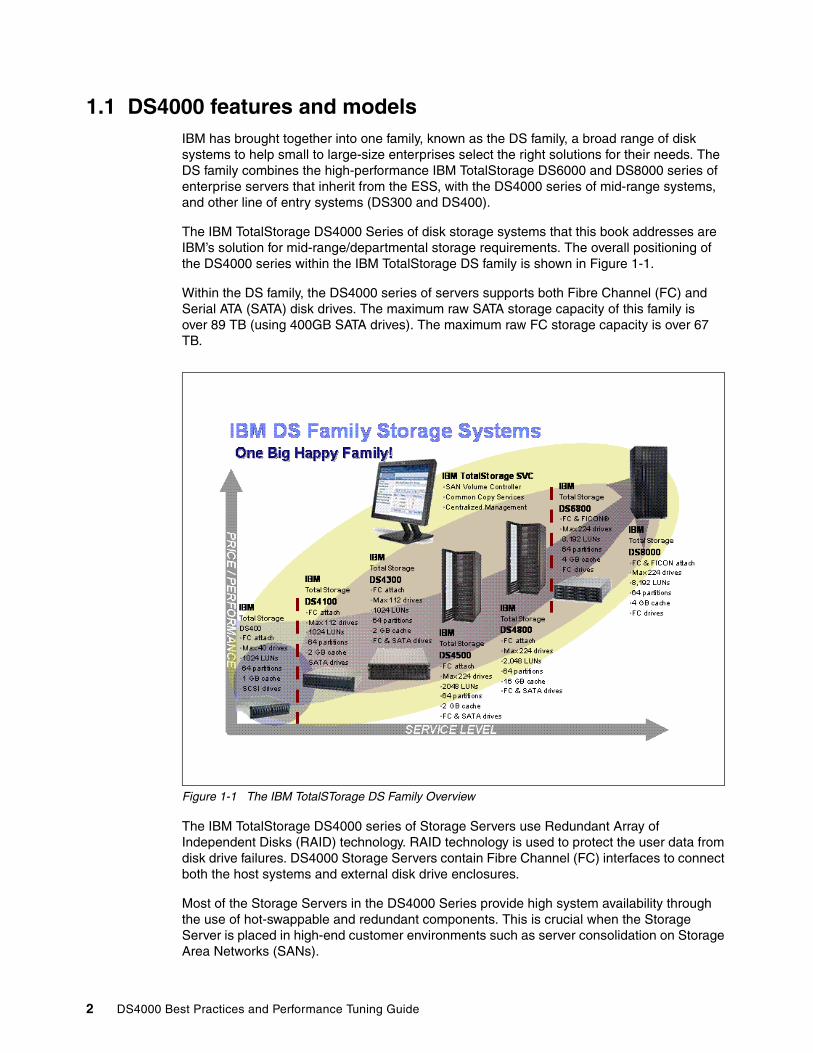
1.1 DS4000 features and modelsIBM has brought together into one family, known as the DS family, a broad range of disk systems to help small to large-size enterprises select the right solutions for their needs. The DS family combines the high-performance IBM TotalStorage DS6000 and DS8000 series of enterprise servers that inherit from the ESS, with the DS4000 series of mid-range systems, and other line of entry systems (DS300 and DS400).
The IBM TotalStorage DS4000 Series of disk storage systems that this book addresses are IBM’s solution for mid-range/departmental storage requirements. The overall positioning of the DS4000 series within the IBM TotalStorage DS family is shown in Figure 1-1.
Within the DS family, the DS4000 series of servers supports both Fibre Channel (FC) and Serial ATA (SATA) disk drives. The maximum raw SATA storage capacity of this family is over 89 TB (using 400GB SATA drives). The maximum raw FC storage capacity is over 67 TB.
Figure 1-1 The IBM TotalSTorage DS Family Overview
The IBM TotalStorage DS4000 series of Storage Servers use Redundant Array of Independent Disks (RAID) technology. RAID technology is used to protect the user data from disk drive failures. DS4000 Storage Servers contain Fibre Channel (FC) interfaces to connect both the host systems and external disk drive enclosures.
Most of the Storage Servers in the DS4000 Series provide high system availability through the use of hot-swappable and redundant components. This is crucial when the Storage Server is placed in high-end customer environments such as server consolidation on Storage Area Networks (SANs).
2 DS4000 Best Practices and Performance Tuning Guide

The DS4000 Storage Servers are as follows:
� IBM TotalStorage DS4100 Storage Server:
The DS4100 Storage Server is an entry-level 2Gbps SATA storage system that is available in a single and dual controller configuration. The DS4100 single controller can have a maximum of 14 SATA disks. The dual controller model supports up to 44.8TB when attaching DS4000 EXP100 expansions. The single controller model has two Fibre Channel host connections and the dual controller provides 4 FC ports.
The DS4100 is designed to interoperate with IBM Eserver® pSeries and IBM Eserver xSeries servers as well as other Intel processor-based and UNIX-based servers. The SATA-based DS4100 supports increased reliability and performance compared to older, non-redundant parallel Advanced Technology Attachment (ATA) products.
� IBM TotalStorage DS4300 Storage Server:
The DS4300 Storage Server is a mid-level, highly scalable 2Gbps Fibre Channel Storage Server, also available in a single and dual controller configurations. It is designed to be a cost-effective, scalable storage server for consolidation and clustering applications. Its modular architecture can support on demand business models by enabling an entry configuration that can easily grow as storage demands increase (up to 44.8 TB of capacity using 400GB SATA drives). Supporting up to 56 Fibre Channel drives (using three EXP710 Expansion units) or 112 SATA drives (using 8 EXP100 Expansion units), it is designed to deliver data throughput of up to 400 MB/s. The DS4300 can provide capacity on demand, allowing unused storage to be brought online for a new host group or an existing volume. The DS4300 can be upgraded to the DS4300 with Turbo feature.
The DS4300 with Turbo feature, facilitates storage consolidation for medium-sized customers. It uses the latest in storage networking technology to provide an end-to-end 2 Gbps Fibre Channel solution (the host interface on base DS4300 is 2 Gbps, while the DS4300 with Turbo feature auto senses to connect to 1 Gbps or 2 Gbps) and offers up to 65 percent read performance improvement. It has higher Fibre Channel drive scalability over the base DS4300, up to 33.6 TB for a total of 112 disks — using a maximum of seven EXP710s. The DS4300 with Turbo feature supports up to 64 storage partitions. The cache has increased from 256 MB per controller on base DS4300 to 1 GB per controller on Turbo; The DS4300 with Turbo feature supports all premium copy features including the Enhanced Remote Mirroring.
� IBM TotalStorage DS4500 Storage Server:
IBM DS4500 Storage Server delivers high disk performance and outstanding reliability for demanding applications in compute-intensive environments. The DS4500 is designed to offer investment protection with advanced functions and flexible features. Designed for today’s on demand business needs, the DS4500 easily scales from 36 GB to over 67 TB (when using FC disks) to support growing storage requirements.
The DS4500 uses 2 Gbps Fibre Channel connectivity to support high performance (790 MB/s throughput from disk) for faster, more responsive access to data. It provides flexibility for multiplatform storage environments by supporting a wide variety of servers, operating systems, and cluster technologies. This Storage Server is well suited for high-performance applications such as online transaction processing (OLTP), data mining, and digital media.
� IBM TotalStorage DS4800 Storage Server:
IBM DS4800 Storage Server delivers breakthrough disk performance and outstanding reliability for demanding applications in compute-intensive environments. The DS4800 offers twice the performance of the DS4500 (up to1600MB/s throughput from disk) and continues the tradition of investment protection with advanced functions and flexible features. The DS4800 is an effective Storage Server for any enterprise seeking performance without borders.
Chapter 1. Introduction to DS4000 and SAN 3

The DS4800 is a newer, simpler hardware design that has only five customer replaceable components. Using 4 Gbps Fibre Channel connectivity, more data paths, and larger cache, the DS4800 greatly improves performance over its predecessor DS4000 models. It is available in three models, the 82A with 4GB of cache, 84A with 8GB of cache, and 88A with 16GB of cache. With eight host ports and eight redundant drive loops on the back-end, the DS4800 is an excellent choice for clients with high-performance computing needs that store and utilize vast amounts of data for high-bandwidth programs and complex application processing, such as those in the energy, entertainment, and scientific research segments.
Most models offers autonomic functions such as Dynamic Volume Expansion and Dynamic Capacity Addition, allowing unused storage to be brought online without stopping operations.
1.1.1 DS4000 Series product comparisonTable 1-1 and Table 1-2 summarize the characteristics of the DS4000 Series of products.
Table 1-1 Comparison of DS4100 versus DS4300
DS Model DS4100 SCU DS4100 DS4300 SCU DS4300 DS4300 Turbo
Model-No. 1724-1SC 1724-100 1722-6LU 1722-60U 1722-60U Turbo
Environment Entry Level Entry Level Midrange Midrange Midrange
Max disks 14 112 14 56 112
Max raw capacity 5.6 TB SATA 44.8 TB SATA 4.2 TB FC 16.8 TB FC44.8 TB SATA
33.6 TB FC44.8 TB SATA
Host interfaces 2 Gbps 2 Gbps 2 Gbps 2 Gbps 2 Gbps
SAN attach (max)
2 FC-SW 4 FC-SW 2 FC-SW 4 FC-SW 4 FC-SW
Direct attach (max)
2 FC-AL 4 FC-AL 2 FC-AL 4 FC-AL 4 FC-AL
Max cache memory
256 MB 256 MB/ cont 256 MB 256 MB/cont 1 GB/cont
IOPS from cache read
N/A N/A N/A 45500* 77500*
IOPS from disk read
N/A N/A N/A 12500* 25000*
Throughput from disk
N/A N/A N/A 400 MB/s* 400 MB/s*
Base/max partitions
0/16 0/16 0/16 0/16 8/64
Copy features2 F F F F,V,E F,V,E
FC/SATA mix NO NO NO YES YES
Available drives FC 10k rpm
N/A N/A 36/73/146/300 GB
36/73/146/300 GB
36/73/146/300 GB
Available drives FC 15k rpm
N/A N/A 36/73/146 GB 18/36/73/146 GB
18/36/73/146 GB
Available drives SATA
400GB 7200 rpm 400GB 7200 rpm N/A 400GB 7200 rpm 400GB 7200 rpm
4 DS4000 Best Practices and Performance Tuning Guide

1) For more than four connections, purchase of additional mini-hubs is required.2) F=FlashCopy®; V=Volume Copy; E=Enhanced Remote Mirroring.Note: * = Performance up to denoted value; may vary according to your particular environment.
Table 1-2 Comparison of DS4500 versus DS4800
1) For more than four connections, purchase of additional mini-hubs is required.2) F=FlashCopy; V=Volume Copy; E=Enhanced Remote Mirroring.Note: * = Performance up to denoted value; may vary according to your particular environment.
DS Model DS4500 DS4800 (4 GB cache)
DS4800 (8 GB cache)
DS4800 (16 GB cache)
Model-No. 1742-900 1815-82A 1815-84A 1815-88A
Environment Midrange to High End
High End High End High End
Max disks 224 224 224 224
Max raw capacity 67.2 TB FC89.6TB SATA
67.2 TB FC89.6 TB SATA
67.2TB FC89.6 TB SATA
67.2TB FC89.6 TB SATA
Host interfaces 2 Gbps 4 Gbps 4 Gbps 4 Gbps
Host connections 4 (up to 8 with mini-hubs)
8 8 8
Drive-side interfaces 2 Gbps 4 Gbps 4 Gbps 4 Gbps
Drive-side connections
4 (2 loop pairs) 8 (4 loop pairs) 8 (4 loop pairs) 8 (4 loop pairs)
SAN attach (max) 4 FC-SW1 8 FC-SW1 8 FC-SW 8 FC-SW
Direct attach (max) 8 FC-AL 8 FC-SW 8 FC-SW 8 FC-SW
Max cache memory 1GB/cont 2 GB/cont 4 GB/cont 8 GB/cont
IOPS from cache read
148000* 550000* 550000* 550000*
IOPS from disk read 38000* 79000* 79000* 79000*
Throughput from disk 790 MB/s* 1600 MB/s* 1600 MB/s* 1600 MB/s*
Base/max partitions 16/64 8/16/64 8/16/64 8/16/64
Copy features3 F,V,E F,V,E F,V,E F,V,E
FC/SATA Drive Intermix
YES YES YES YES
Available drives FC 10k rpm
36/73/146/300 GB 36/73/146/300 GB 36/73/146/300 GB 36/73/146/300 GB
Available drives FC 15k rpm
18/36/73/146 GB 36/73/146 GB 36/73/146 GB 36/73/146 GB
Available drives SATA
400GB 7200 rpm 400GB 7200 rpm 400GB 7200 rpm 400GB 7200 rpm
Chapter 1. Introduction to DS4000 and SAN 5

400GB 7,200 RPM SATA disk driveA new, higher capacity SATA disk drive module is now available for the IBM TotalStorage DS4000 series midrange disk systems. The DS4000 400GB 7,200 rpm SATA disk drive module is available for the DS4100 SATA Midrange Disk System and the DS4000 EXP100 SATA Storage Expansion Units. The 400 GB disk drives modules can be installed in the internal drive bays of the DS4100 and the DS4000 EXP100 to increase the physical storage capacity of each of these devices to a maximum of 5.6 terabytes (TB) in a single enclosure.
Effective December 16th 2005, for DS4100 and EXP100, the 400GB SATA drive replaces the 250GB SATA Disk Drive Module, which is discontinued.
You can mix 400GB disks with existing 250 GB disks. However, installation of the DS4000 SATA 400 GB/7200 DDM, requires the DS4000 series product into which this DDM is installed, and each DS4000 series product in the configuration to be at a specific minimum controller firmware level or specific minimum EXP100 expansion enclosure ESM firmware level. Please refer to the IBM TotalStorage DS4000 support Web site:
http://www.ibm.com/servers/storage/support/disk/
IBM TotalStorage SAN Virtualization ControllerAlthough not directly a topic covered in this redbook, it is worth mentioning here the IBM TotalStorage SAN Virtualization Controller (SVC) as it compliments the DS4000 Storage servers for performance, scalability and reliability.
Storage needs are rising, and the challenge of managing disparate storage systems is growing. IBM TotalStorage SAN Volume Controller brings storage devices together in a virtual pool to make all storage appear as:
� One logical device to centrally manage and to allocate capacity as needed � One solution to help achieve the most effective use of key storage resources on demand
Virtualization solutions can be implemented in the storage network, in the server, or in the storage device itself. The IBM storage virtualization solution is SAN-based, which helps allow for a more open virtualization implementation. Locating virtualization in the SAN, and therefore in the path of input/output (I/O) activity, helps to provide a solid basis for policy-based management. The focus of IBM on open standards means its virtualization solution supports freedom of choice in storage-device vendor selection.
The IBM TotalStorage SAN Volume Controller solution is to:
� Simplify storage management� Reduce IT data storage complexity and costs while enhancing scalability� Extend on-demand flexibility and resiliency to the IT infrastructure
For more details on the SVC, see the IBM Redbook IBM TotalStorage SAN Volume Controller, SG24-6423.
1.2 DS4000 Storage ManagerThe DS4000 Storage Manager software is used primarily to configure RAID arrays and logical drives, assign logical drives to hosts, replace and rebuild failed disk drives, expand the size of the arrays and logical drives, and convert from one RAID level to another. It allows troubleshooting and management tasks, like checking the status of the Storage Server components, updating the firmware of the RAID controllers, and managing the Storage Server. Finally, it offers advanced functions such as FlashCopy, Volume Copy, and Enhanced Remote Mirroring.
6 DS4000 Best Practices and Performance Tuning Guide

The Storage Manager software is now packaged as follows:
� Host-based software:
– Storage Manager 9.1x Client (SMclient):
The SMclient component provides the graphical user interface (GUI) for managing Storage Subsystems through the Ethernet network or from the host computer.
– Storage Manager 9.1x Runtime (SMruntime):
The SMruntime is a Java runtime environment that is required for the SMclient to function. It is not available on every platform as a separate package, but in those cases, it has been bundled into the SMclient package.
– Storage Manager 9.1x Agent (SMagent):
The SMagent package is an optional component that allows in-band management of the DS4000 Storage Server.
– Storage Manager 9.1x Utilities (SMutil):
The Storage Manager Utilities package contains command line tools for making logical drives available to the operating system.
– Redundant Dual Active Controller driver (RDAC):
RDAC is a Fibre Channel I/O path failover driver that is installed on host computers. This is only required if the host computer has a host bus adapter (HBA) installed.
� Controller-based software:
– DS4000 Storage Server Controller firmware and NVSRAM:
The controller firmware and NVSRAM are always installed as a pair and provide the “brains” of the DS4000 Storage Server.
– DS4000 Storage Server Environmental Service Modules (ESM) firmware:
The ESM firmware controls the interface between the controller and the drives.
– DS4000 Storage Server Drive firmware:
The drive firmware is the software that tells the Fibre Channel (FC) drives how to behave on the FC loop.
1.3 Introduction to SANFor businesses, data access is critical and requires performance, availability, and flexibility. In other words, there is a need for a data access network that is fast, redundant (multipath), easy to manage, and always available. That network is a Storage Area Network (SAN).
A SAN is a high-speed network that enables the establishment of direct connections between storage devices and hosts (servers) within the distance supported by Fibre Channel.
Note: Always consult IBM TotalStorage DS4000 Interoperability matrix for information on the latest supported Storage Manager version for your DS4000 system; it is available on the Web at:
http://www.ibm.com/servers/storage/disk/ds4000/interop-matrix.html
Chapter 1. Introduction to DS4000 and SAN 7
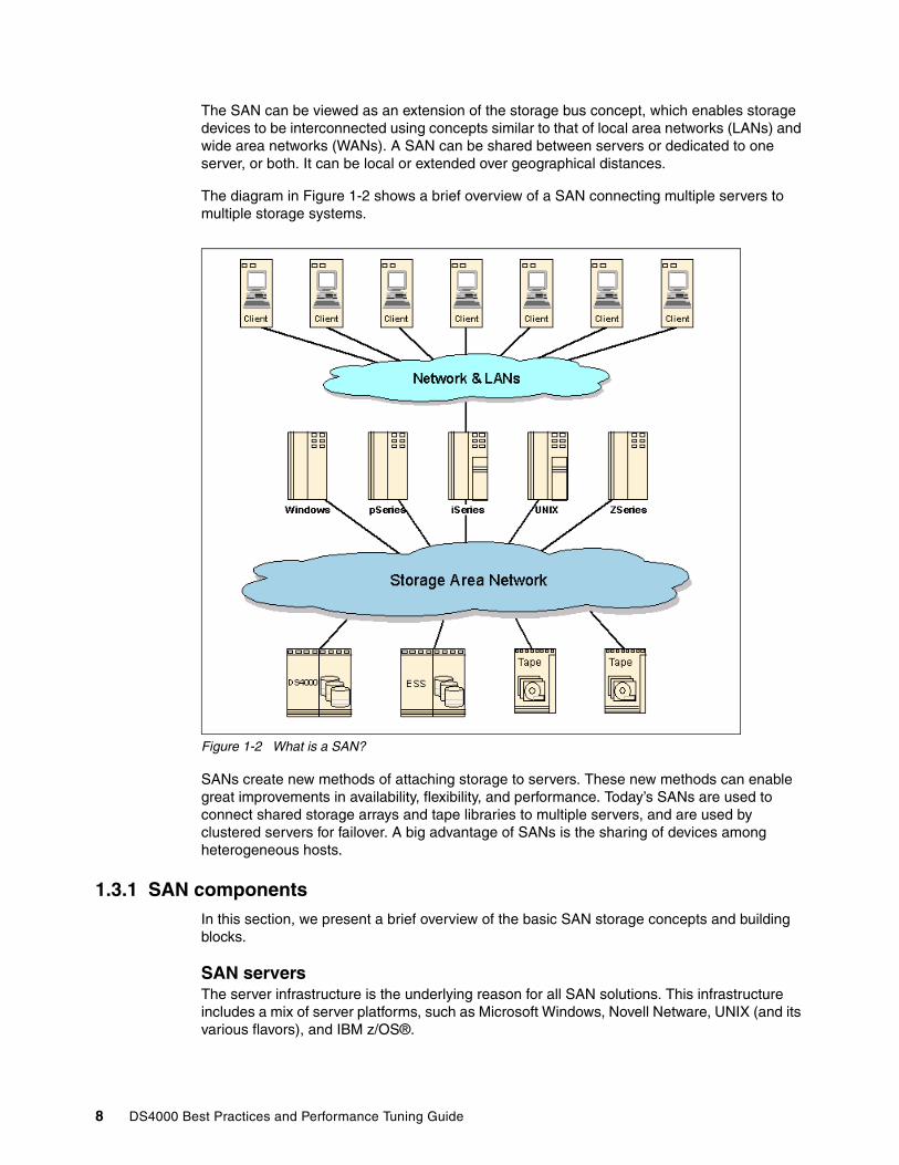
The SAN can be viewed as an extension of the storage bus concept, which enables storage devices to be interconnected using concepts similar to that of local area networks (LANs) and wide area networks (WANs). A SAN can be shared between servers or dedicated to one server, or both. It can be local or extended over geographical distances.
The diagram in Figure 1-2 shows a brief overview of a SAN connecting multiple servers to multiple storage systems.
Figure 1-2 What is a SAN?
SANs create new methods of attaching storage to servers. These new methods can enable great improvements in availability, flexibility, and performance. Today’s SANs are used to connect shared storage arrays and tape libraries to multiple servers, and are used by clustered servers for failover. A big advantage of SANs is the sharing of devices among heterogeneous hosts.
1.3.1 SAN componentsIn this section, we present a brief overview of the basic SAN storage concepts and building blocks.
SAN serversThe server infrastructure is the underlying reason for all SAN solutions. This infrastructure includes a mix of server platforms, such as Microsoft Windows, Novell Netware, UNIX (and its various flavors), and IBM z/OS®.
8 DS4000 Best Practices and Performance Tuning Guide
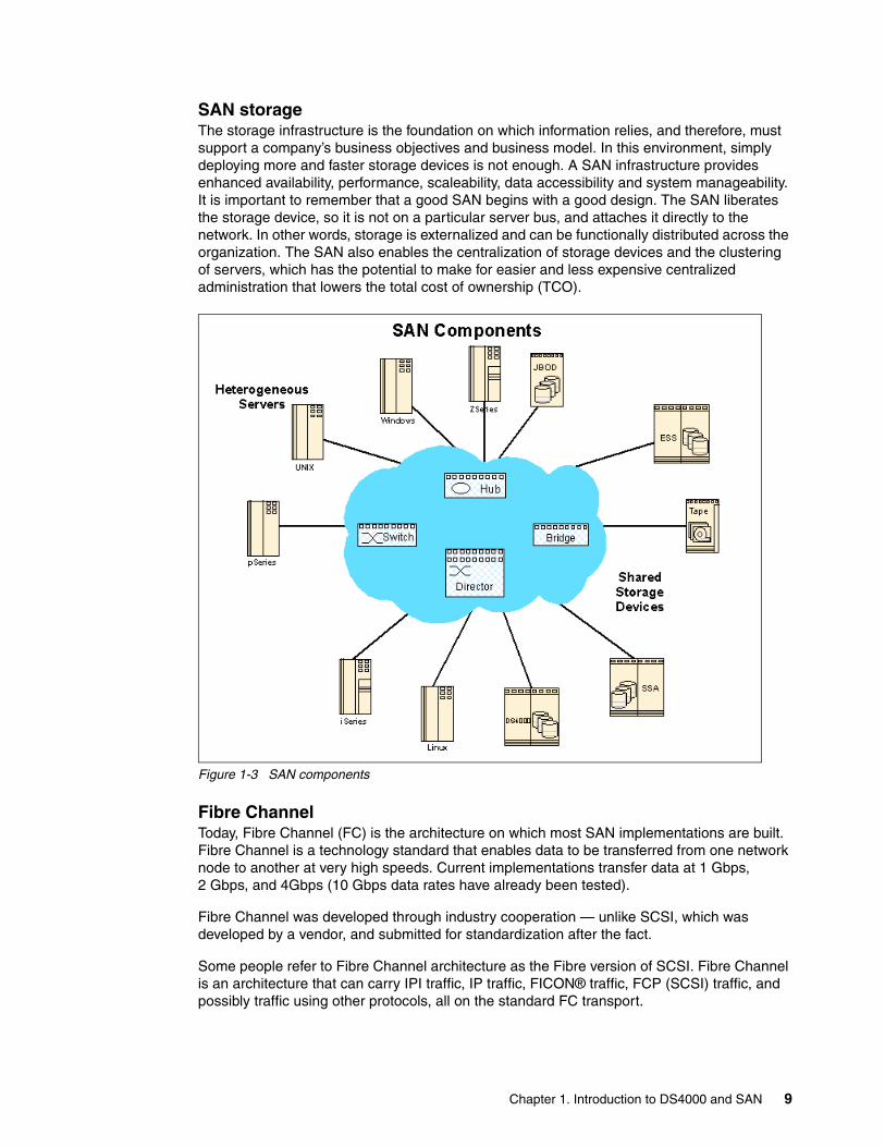
SAN storageThe storage infrastructure is the foundation on which information relies, and therefore, must support a company’s business objectives and business model. In this environment, simply deploying more and faster storage devices is not enough. A SAN infrastructure provides enhanced availability, performance, scaleability, data accessibility and system manageability. It is important to remember that a good SAN begins with a good design. The SAN liberates the storage device, so it is not on a particular server bus, and attaches it directly to the network. In other words, storage is externalized and can be functionally distributed across the organization. The SAN also enables the centralization of storage devices and the clustering of servers, which has the potential to make for easier and less expensive centralized administration that lowers the total cost of ownership (TCO).
Figure 1-3 SAN components
Fibre Channel Today, Fibre Channel (FC) is the architecture on which most SAN implementations are built. Fibre Channel is a technology standard that enables data to be transferred from one network node to another at very high speeds. Current implementations transfer data at 1 Gbps, 2 Gbps, and 4Gbps (10 Gbps data rates have already been tested).
Fibre Channel was developed through industry cooperation — unlike SCSI, which was developed by a vendor, and submitted for standardization after the fact.
Some people refer to Fibre Channel architecture as the Fibre version of SCSI. Fibre Channel is an architecture that can carry IPI traffic, IP traffic, FICON® traffic, FCP (SCSI) traffic, and possibly traffic using other protocols, all on the standard FC transport.
Chapter 1. Introduction to DS4000 and SAN 9
SAN topologiesFibre Channel interconnects nodes using three physical topologies that can have variants. These three topologies are:
� Point-to-point: The point-to-point topology consists of a single connection between two nodes. All the bandwidth is dedicated to these two nodes.
� Loop: In the loop topology, the bandwidth is shared between all the nodes connected to the loop. The loop can be wired node-to-node; however, if a node fails or is not powered on, the loop is out of operation. This is overcome by using a hub. A hub opens the loop when a new node is connected, and closes it when a node disconnects.
� Switched or fabric: A switch enables multiple concurrent connections between nodes. There are two types of switches: circuit switches and frame switches. Circuit switches establish a dedicated connection between two nodes, whereas frame switches route frames between nodes and establish the connection only when needed. This is also known as switched fabric.
SAN interconnectsFibre Channel employs a fabric to connect devices. A fabric can be as simple as a single cable connecting two devices. However, the term is most often used to describe a more complex network using cables and interface connectors, HBAs, extenders, and switches.
Fibre Channel switches function in a manner similar to traditional network switches to provide increased bandwidth, scalable performance, an increased number of devices, and in some cases, increased redundancy. Fibre Channel switches vary from simple edge switches to enterprise-scalable core switches or Fibre Channel directors.
Inter-Switch Links (ISLs)Switches can be linked together using either standard connections or Inter-Switch Links. Under normal circumstances, traffic moves around a SAN using the Fabric Shortest Path First (FSPF) protocol. This allows data to move around a SAN from initiator to target using the quickest of alternate routes. However, it is possible to implement a direct, high-speed path between switches in the form of ISLs.
TrunkingInter-Switch Links can be combined into logical groups to form trunks. In IBM TotalStorage switches, trunks can be groups of up to four ports on a switch connected to four ports on a second switch. At the outset, a trunk master is defined, and subsequent trunk slaves can be added. This has the effect of aggregating the throughput across all links. Therefore, in the case of switches with 2 Gbps ports, we can trunk up to four ports, allowing for an 8 Gbps Inter-Switch Link.
1.3.2 SAN zoningA zone is a group of fabric-connected devices arranged into a specified grouping. Zones can vary in size depending on the number of fabric-connected devices, and devices can belong to more than one zone.
Note: The fabric (or switched) topology gives the most flexibility and ability to grow your installation for future needs.
10 DS4000 Best Practices and Performance Tuning Guide

Typically, you use zones to do the following tasks:
� Provide security: Use zones to provide controlled access to fabric segments and to establish barriers between operating environments. For example, isolate systems with different uses or protect systems in a heterogeneous environment.
� Customize environments: Use zones to create logical subsets of the fabric to accommodate closed user groups or to create functional areas within the fabric. For example, include selected devices within a zone for the exclusive use of zone members, or create separate test or maintenance areas within the fabric.
� Optimize IT resources: Use zones to consolidate equipment logically for IT efficiency, or to facilitate time-sensitive functions. For example, create a temporary zone to back up non-member devices.
Without zoning, failing devices that are no longer following the defined rules of fabric behavior might attempt to interact with other devices in the fabric. This type of event would be similar to an Ethernet device causing broadcast storms or collisions on the whole network, instead of being restricted to one single segment or switch port. With zoning, these failing devices cannot affect devices outside of their zone.
Zone typesA zone member can be specified using one of the following zone types:
Port level zone A zone containing members specified by switch ports (domain ID, port number) only. Port level zoning is enforced by hardware in the switch.
WWN zone A zone containing members specified by device World Wide Name (WWN) only. WWN zones are hardware enforced in the switch.
Mixed zone A zone containing some members specified by WWN and some members specified by switch port. Mixed zones are software enforced through the fabric name server.
Zones can be hardware enforced or software enforced:
� In a hardware-enforced zone, zone members can be specified by physical port number, or in recent switch models, through WWN, but not within the same zone.
� A software-enforced zone is created when a port member and WWN members are in the same zone.
For more complete information regarding Storage Area Networks, refer to the following IBM Redbooks:
� Introduction to Storage Area Networks, SG24-5470� IBM SAN Survival Guide, SG24-6143
Note: Utilizing zoning is always a good idea with SANs that include more than one host. With SANs that include more than one operating system, or SANs that contain both tape and disk devices, it is mandatory.
Note: You do not explicitly specify a type of enforcement for a zone. The type of zone enforcement (hardware or software) depends on the type of member it contains (WWNs and/or ports).
Chapter 1. Introduction to DS4000 and SAN 11
Zoning configurationZoning is not that hard to understand or configure. Using your switch’s management software, use WWN zoning to set up each zone so that it contains one server port, and whatever storage device ports that host port requires access to. You do not need to create a separate zone for each source/destination pair. Do not put disk and tape in the same zone.
When configuring WWN-based zoning, it is important to always use the Port WWN, not the Node WWN. With many systems, the Node WWN is based on the Port WWN of the first adapter detected by the HBA driver. If the adapter the Node WWN was based on were to fail, and you based your zoning on the Node WWN, your zoning configuration would become invalid. Subsequently the host with the failing adapter would completely lose access to the storage attached to that switch.
Keep in mind that you will need to update the zoning information, should you ever need to replace a Fibre Channel adapter in one of your servers. Most storage systems such as the DS4000, Enterprise Storage Server®, and IBM Tape Libraries have a WWN tied to the Vital Product Data of the system unit, so individual parts may usually be replaced with no effect on zoning.
For more details on configuring zoning with your particular switch, see the IBM Redbook, Implementing an Open IBM SAN, SG24-6116.
12 DS4000 Best Practices and Performance Tuning Guide
Chapter 2. DS4000 planning tasks
Careful planning is essential to any new storage installation. This chapter provides guidelines to help you in the planning process.
Choosing the right equipment and software, and also knowing what the right settings are for a particular installation, can be challenging. Every installation has to answer these questions and accommodate specific requirements, and there can be many variations in the solution.
Well-thought design and planning prior to the implementation will help you get the most out of your investment for the present and protect it for the future.
During the planning process, you need to answer numerous questions about your environment:
� What are my SAN requirements?� What hardware do I need to buy?� What reliability do I require?� What redundancy do I need? (for example, do I need off-site mirroring?)� What compatibility issues do I need to address?� Will I use any storage virtualization product such as the IBM SAN Volume Controller?� What operating system am I going to use (existing or new installation)?� What applications will access the storage subsystem?� What are the hardware and software requirements of these applications?� What will be the physical layout of the installation? Only local site, or remote sites as well?� What level of performance do I need?� How much does it cost?
This list of questions is not exhaustive, and as you can see, some go beyond simply configuring the DS4000 Storage Server.
Some recommendations in this chapter come directly from experience with various DS4000 installations at customer sites.
2
© Copyright IBM Corp. 2005, 2006. All rights reserved. 13

2.1 Planning your SAN and Storage ServerWhen planning to set up a Storage Area Network (SAN), you want the solution to not only answer your current requirements, but also be able to fulfill future needs.
First, the SAN should be able to accommodate a growing demand in storage (it is estimated that storage need doubles every two years). Second, the SAN must be able to keep up with the constant evolution of technology and resulting hardware upgrades and improvements. It is estimated that a storage installation needs to be upgraded every two to three years.
Ensuring compatibility among different pieces of equipment is crucial when planning the installation. The important question is what device works with what, and also who has tested and certified (desirable) that equipment.
When designing a SAN storage solution, it is good practice to complete the following steps:
1. Produce a statement outlining the solution requirements that can be used to determine the type of configuration you need. It should also be used to cross-check that the solution design delivers the basic requirements. The statement should have easily defined bullet points covering the requirements, for example:
– New installation or upgrade of existing infrastructure– Types of applications accessing the SAN (are the applications I/O intensive or high
throughput?)– Required capacity– Required redundancy levels– Type of data protection needed– Current data growth patterns for your environment– Is the current data more read or write based?– Backup strategies in use (Network, LAN-free or Server-less)– Premium Features required (FC/SATA Intermix, Partitioning, FlashCopy, Volume Copy
or Enhanced Remote Mirroring)– Number of host connections required– Types of hosts and operating systems that will connect to the SAN– What zoning is required– Distances between equipment and sites (if there is there more than one site)
2. Produce a hardware checklist. It should cover such items that require you to:
– Make an inventory of existing hardware infrastructure. Ensure that any existing hardware meets minimum hardware requirements and is supported with the DS4000.
– Make a complete list of the planned hardware requirements.
– Ensure that you have enough rack space for future capacity expansion.
– Ensure that power and environmental requirements are met.
– Ensure that your existing Fibre Channel switches and cables are properly configured.
3. Produce a software checklist to cover all the required items that need to be certified and checked. It should include such items that require you to:
– Ensure that the existing versions of firmware and storage management software are up to date.
– Ensure host operating systems are supported with the DS4000. Check the IBM TotalStorage DS4000 interoperability matrix available at this Web site:
http://www.ibm.com/servers/storage/disk/ds4000/interop-matrix.html
14 DS4000 Best Practices and Performance Tuning Guide
This list is not exhaustive, but the creation of the statements is an exercise in information gathering and planning; it assists you in a greater understanding of what your needs are in your current environment and creates a clearer picture of your future requirements. The goal should be quality rather than quantity of information.
Use this planning chapter as a reference that can assist you to gather the information for the statements.
Understanding the applications is another important consideration in planning for your DS4000. Applications can typically be either be I/O intensive (high number of I/O per second or IOPS), or characterized by large I/O requests (that is, high throughput or Mbps).
� Typical examples of high IOPS environments are Online Transaction Processing (OLTP), database, and MS Exchange servers. These have random writes and fewer reads.
� Typical examples of high throughput applications are Data Mining, Imaging, and Backup storage pools. These have large sequential reads and writes.
Section 4.1, “Workload types” on page 114 provides a detailed discussion and considerations for application types. The planning for each application type affects hardware purchases and configuration options.
By understanding your data and applications, you can also better understand growth patterns. Being able to estimate an expected growth is vital for the capacity planning of your DS4000 Storage Server installation. Clearly indicate the expected growth in the planning documents, to act as a guide: The actual patterns may differ from the plan but that is the dynamics of your environment.
Selecting the right DS4000 Storage Server model for your current and perceived future needs is one of the most crucial decisions that will have to be made. The good side, however, is that the DS4000 offers scalability and expansion flexibility. Premium Features can be purchased and installed at a later time to add functionality to the storage server.
In any case, it is perhaps better to purchase a higher model than one strictly dictated by your current requirements and expectations. This will allow for greater performance and scalability as your needs and data grow.
2.1.1 SAN zoning for DS4000Zoning is an important part of integrating a DS4000 Storage Server in a SAN. When done correctly, it can eliminate many common problems.
A best practice is to create a zone for the connection between the host bus adapter (HBA) and controller A and a separate zone that contains the same HBA to controller B. Then create additional zones for access to other resources. This isolates each zone down to its simplest form.
Best Practice: Create separate zones for the connection between the HBA and each controller (one zone for HBA to controller A and one zone for HBA to controller B). This isolates each zone to its simplest form.
Chapter 2. DS4000 planning tasks 15

Disk and tape access should not be on the same HBA and should not be in the same zone.
Enhanced Remote Mirroring considerationsWhen using Enhanced Remote Mirroring (ERM), you must create two additional zones:
� The first zone contains the ERM source DS4000 Controller A and ERM target DS4000 Controller A.
� The second zone contains the ERM source DS4000 Controller B and ERM target DS4000 Controller B.
2.2 Physical components planningIn this section, we review elements related to physical characteristics of an installation, such as rack considerations, fibre cables, Fibre Channel adapters, and other elements related to the structure of the storage system and disks, including enclosures, arrays, controller ownership, segment size, storage partitioning, caching, hot spare drives, and Enhanced Remote Mirroring.
2.2.1 Rack considerationsThe DS4000 Storage Server and possible expansions are mounted in rack enclosures.
General planningConsider the following general planning guidelines:
� Determine:
– The size of the floor area required by the equipment:• Floor-load capacity• Space needed for expansion• Location of columns
– The power and environmental requirements.
Create a floor plan to check for clearance problems. Be sure to include the following considerations on the layout plan:
� Service clearances required for each rack or suite of racks.
� If the equipment is on a raised floor, determine:
– The height of the raised floor– Things that might obstruct cable routing
Important: Disk and tape should be on separate HBAs, following the best practice for zoning; then the disk and tape access will also be in separate zones. With some UNIX systems, this is supported by the DS4000 due to hardware limitations, but generally HBA sharing is strongly not recommended.
For systems such as the IBM BladeCenter® servers that have a limited number of FC ports available, we suggest that you perform a LAN backup instead of a LAN-free backup directly to the tape drives.
Important: On the DS4100, DS4300, and DS4500 the ERM port is second set of ports on Controller A and Controller B.
On the DS4800 the ERM port is port 4 on Controller A and Controller B.
16 DS4000 Best Practices and Performance Tuning Guide
� If the equipment is not on a raised floor, determine:
– The placement of cables to minimize obstruction
– If the cable routing is indirectly between racks (such as along walls or suspended), the amount of additional cable needed
– Cleanliness of floors, so that the fan units will not attract foreign material such as dust or carpet fibers
� Location of:
– Power receptacles– Air conditioning equipment, placement of grilles and controls– File cabinets, desks, and other office equipment– Room emergency power-off controls– All entrances, exits, windows, columns, and pillars– Fire control systems
� Check access routes for potential clearance problems through doorways and passage ways, around corners, and in elevators for racks and additional hardware that will require installation.
� Store all spare materials that can burn in properly designed and protected areas.
Rack layoutTo be sure you have enough space for the racks, create a floor plan before installing the racks. You might need to prepare and analyze several layouts before choosing the final plan.
If you are installing the racks in two or more stages, prepare a separate layout for each stage.
Consider the following things when you make a layout:
� The flow of work and personnel within the area
� Operator access to units, as required
� If the rack is on a raised floor:
– Ensure adequate cooling and ventilation
� If the rack is not on a raised floor, determine:
– The maximum cable lengths– The need for cable guards, ramps, etc. to protect equipment and personnel
� Location of any planned safety equipment.
� Future expansion.
Review the final layout to ensure that cable lengths are not too long and that the racks have enough clearance.
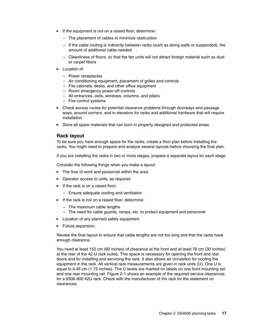
You need at least 152 cm (60 inches) of clearance at the front and at least 76 cm (30 inches) at the rear of the 42-U rack suites. This space is necessary for opening the front and rear doors and for installing and servicing the rack. It also allows air circulation for cooling the equipment in the rack. All vertical rack measurements are given in rack units (U). One U is equal to 4.45 cm (1.75 inches). The U levels are marked on labels on one front mounting rail and one rear mounting rail. Figure 2-1 shows an example of the required service clearances for a 9306-900 42U rack. Check with the manufacturer of the rack for the statement on clearances.
Chapter 2. DS4000 planning tasks 17
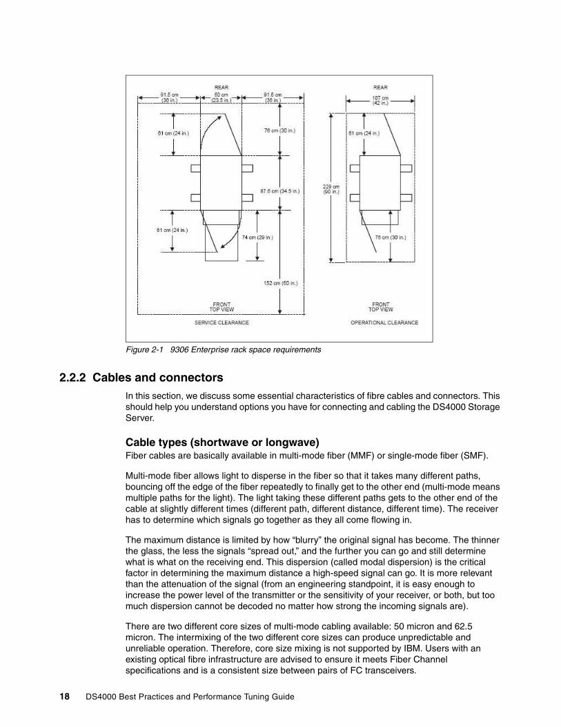
Figure 2-1 9306 Enterprise rack space requirements
2.2.2 Cables and connectorsIn this section, we discuss some essential characteristics of fibre cables and connectors. This should help you understand options you have for connecting and cabling the DS4000 Storage Server.
Cable types (shortwave or longwave)Fiber cables are basically available in multi-mode fiber (MMF) or single-mode fiber (SMF).
Multi-mode fiber allows light to disperse in the fiber so that it takes many different paths, bouncing off the edge of the fiber repeatedly to finally get to the other end (multi-mode means multiple paths for the light). The light taking these different paths gets to the other end of the cable at slightly different times (different path, different distance, different time). The receiver has to determine which signals go together as they all come flowing in.
The maximum distance is limited by how “blurry” the original signal has become. The thinner the glass, the less the signals “spread out,” and the further you can go and still determine what is what on the receiving end. This dispersion (called modal dispersion) is the critical factor in determining the maximum distance a high-speed signal can go. It is more relevant than the attenuation of the signal (from an engineering standpoint, it is easy enough to increase the power level of the transmitter or the sensitivity of your receiver, or both, but too much dispersion cannot be decoded no matter how strong the incoming signals are).
There are two different core sizes of multi-mode cabling available: 50 micron and 62.5 micron. The intermixing of the two different core sizes can produce unpredictable and unreliable operation. Therefore, core size mixing is not supported by IBM. Users with an existing optical fibre infrastructure are advised to ensure it meets Fiber Channel specifications and is a consistent size between pairs of FC transceivers.
18 DS4000 Best Practices and Performance Tuning Guide

Single-mode fiber (SMF) is so thin (9 microns) that the light can barely “squeeze” through and it tunnels through the center of the fiber using only one path (or mode). This behavior can be explained (although not simply) through the laws of optics and physics. The result is that because there is only one path that the light takes to the receiver, there is no “dispersion confusion” at the receiver. However, the concern with single mode fiber is attenuation of the signal. Table 2-1 lists the supported distances.
Table 2-1 Cable type overview
Note that the “maximum distance” shown in Table 2-1 is just that, a maximum. Low quality fiber, poor terminations, excessive numbers of patch panels, etc., can cause these maximums to be far shorter. At the time of writing this book, only the 50 micron MMF (shortwave) cable is officially supported on the DS4800 for 4 Gbps connectivity.
All IBM fiber feature codes that are orderable with the DS4000 will meet the standards.
Interfaces, connectors, and adaptersIn Fibre Channel technology, frames are moved from source to destination using gigabit transport, which is a requirement to achieve fast transfer rates. To communicate with gigabit transport, both sides have to support this type of communication. This is accomplished by using specially designed interfaces that can convert other communication transport into gigabit transport.
The interfaces that are used to convert the internal communication transport of gigabit transport are, depending on the DS4000 model either Small Form Factor Transceivers (SFF), also often called Small Form Pluggable (SFP) or Gigabit Interface Converters (GBIC). See Figure 2-2.
Obviously, the particular connectors used to connect a fiber to a component will depend upon the receptacle into which they are being plugged.
Figure 2-2 Small Form Pluggable (SFP) with LC connector Fibre Cable
Fiber type Speed Maximum distance
9 micron SMF (longwave) 1 Gbps 10 km
9 micron SMF (longwave) 2 Gbps 2 km
50 micron MMF (shortwave) 1 Gbps 500 m
50 micron MMF (shortwave) 2 Gbps 300 m
50 micron MMF (shortwave) 4 Gbps 150 m
62.5 micron MMF (shortwave) 1 Gbps 175 m/300 m
62.5 micron MMF (shortwave) 2 Gbps 90 m/150 m
Chapter 2. DS4000 planning tasks 19
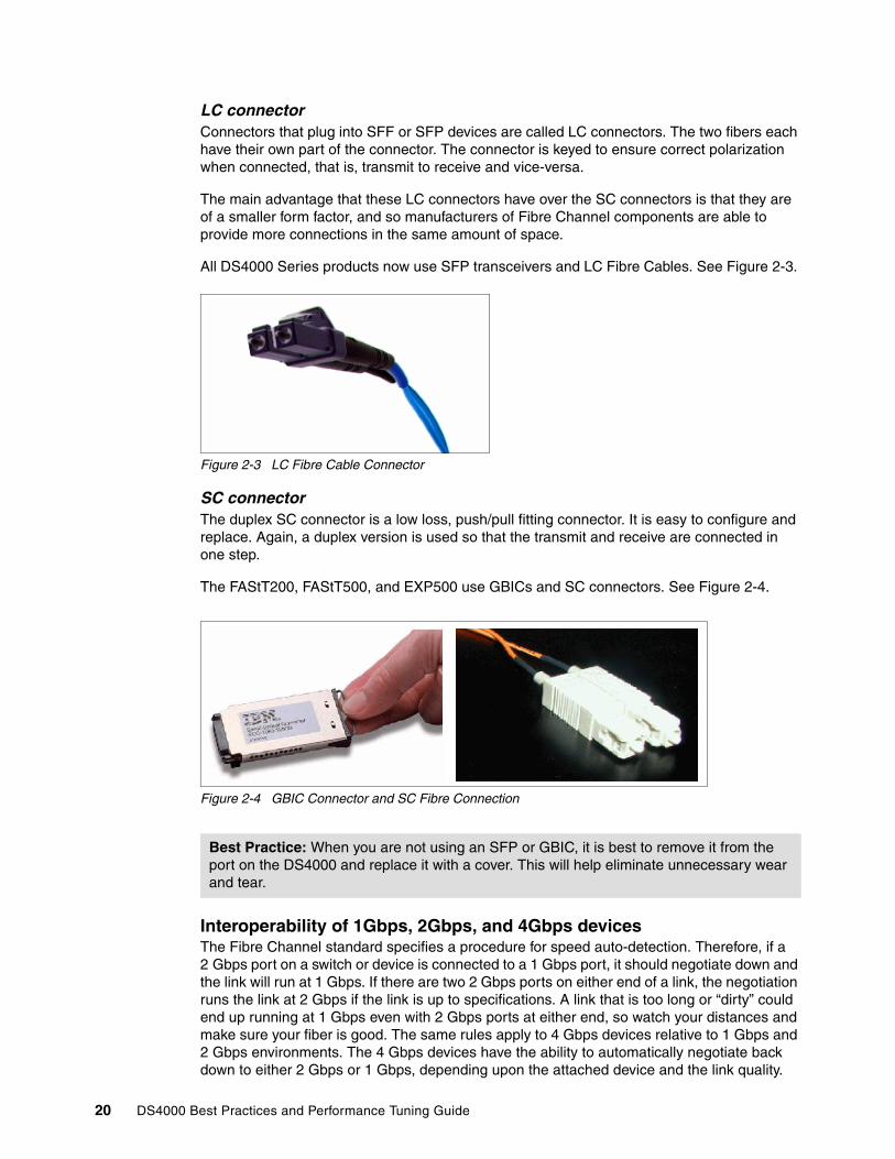
LC connectorConnectors that plug into SFF or SFP devices are called LC connectors. The two fibers each have their own part of the connector. The connector is keyed to ensure correct polarization when connected, that is, transmit to receive and vice-versa.
The main advantage that these LC connectors have over the SC connectors is that they are of a smaller form factor, and so manufacturers of Fibre Channel components are able to provide more connections in the same amount of space.
All DS4000 Series products now use SFP transceivers and LC Fibre Cables. See Figure 2-3.
Figure 2-3 LC Fibre Cable Connector
SC connectorThe duplex SC connector is a low loss, push/pull fitting connector. It is easy to configure and replace. Again, a duplex version is used so that the transmit and receive are connected in one step.
The FAStT200, FAStT500, and EXP500 use GBICs and SC connectors. See Figure 2-4.
Figure 2-4 GBIC Connector and SC Fibre Connection
Interoperability of 1Gbps, 2Gbps, and 4Gbps devicesThe Fibre Channel standard specifies a procedure for speed auto-detection. Therefore, if a 2 Gbps port on a switch or device is connected to a 1 Gbps port, it should negotiate down and the link will run at 1 Gbps. If there are two 2 Gbps ports on either end of a link, the negotiation runs the link at 2 Gbps if the link is up to specifications. A link that is too long or “dirty” could end up running at 1 Gbps even with 2 Gbps ports at either end, so watch your distances and make sure your fiber is good. The same rules apply to 4 Gbps devices relative to 1 Gbps and 2 Gbps environments. The 4 Gbps devices have the ability to automatically negotiate back down to either 2 Gbps or 1 Gbps, depending upon the attached device and the link quality.
Best Practice: When you are not using an SFP or GBIC, it is best to remove it from the port on the DS4000 and replace it with a cover. This will help eliminate unnecessary wear and tear.
20 DS4000 Best Practices and Performance Tuning Guide
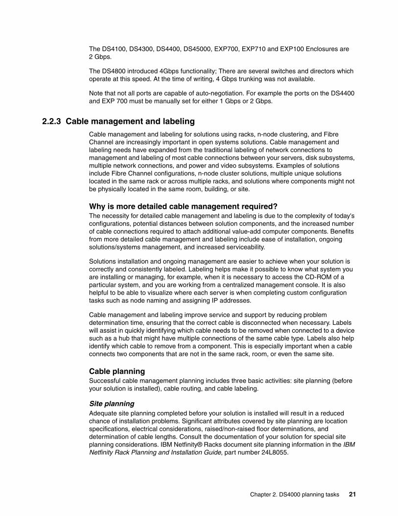
The DS4100, DS4300, DS4400, DS45000, EXP700, EXP710 and EXP100 Enclosures are 2 Gbps.
The DS4800 introduced 4Gbps functionality; There are several switches and directors which operate at this speed. At the time of writing, 4 Gbps trunking was not available.
Note that not all ports are capable of auto-negotiation. For example the ports on the DS4400 and EXP 700 must be manually set for either 1 Gbps or 2 Gbps.
2.2.3 Cable management and labeling Cable management and labeling for solutions using racks, n-node clustering, and Fibre Channel are increasingly important in open systems solutions. Cable management and labeling needs have expanded from the traditional labeling of network connections to management and labeling of most cable connections between your servers, disk subsystems, multiple network connections, and power and video subsystems. Examples of solutions include Fibre Channel configurations, n-node cluster solutions, multiple unique solutions located in the same rack or across multiple racks, and solutions where components might not be physically located in the same room, building, or site.
Why is more detailed cable management required?The necessity for detailed cable management and labeling is due to the complexity of today's configurations, potential distances between solution components, and the increased number of cable connections required to attach additional value-add computer components. Benefits from more detailed cable management and labeling include ease of installation, ongoing solutions/systems management, and increased serviceability.
Solutions installation and ongoing management are easier to achieve when your solution is correctly and consistently labeled. Labeling helps make it possible to know what system you are installing or managing, for example, when it is necessary to access the CD-ROM of a particular system, and you are working from a centralized management console. It is also helpful to be able to visualize where each server is when completing custom configuration tasks such as node naming and assigning IP addresses.
Cable management and labeling improve service and support by reducing problem determination time, ensuring that the correct cable is disconnected when necessary. Labels will assist in quickly identifying which cable needs to be removed when connected to a device such as a hub that might have multiple connections of the same cable type. Labels also help identify which cable to remove from a component. This is especially important when a cable connects two components that are not in the same rack, room, or even the same site.
Cable planningSuccessful cable management planning includes three basic activities: site planning (before your solution is installed), cable routing, and cable labeling.
Site planningAdequate site planning completed before your solution is installed will result in a reduced chance of installation problems. Significant attributes covered by site planning are location specifications, electrical considerations, raised/non-raised floor determinations, and determination of cable lengths. Consult the documentation of your solution for special site planning considerations. IBM Netfinity® Racks document site planning information in the IBM Netfinity Rack Planning and Installation Guide, part number 24L8055.
Chapter 2. DS4000 planning tasks 21
Cable routingWith effective cable routing, you can keep your solution's cables organized, reduce the risk of damaging cables, and allow for affective service and support. To assist with cable routing, IBM recommends the following guidelines:
� When installing cables to devices mounted on sliding rails:
– Run the cables neatly along equipment cable-management arms and tie the cables to the arms. (Obtain the cable ties locally.)
– Take particular care when attaching fiber optic cables to the rack. Refer to the instructions included with your fiber optic cables for guidance on minimum radius, handling, and care of fiber optic cables.
– Run the cables neatly along the rack rear corner posts.
– Use cable ties to secure the cables to the corner posts.
– Make sure the cables cannot be pinched or cut by the rack rear door.
– Run internal cables that connect devices in adjoining racks through the open rack sides.
– Run external cables through the open rack bottom.
– Leave enough slack so that the device can be fully extended without putting a strain on the cables.
– Tie the cables so that the device can be retracted without pinching or cutting the cables.
� To avoid damage to your fiber-optic cables, follow these guidelines:
– Use great care when utilizing cable management arms.
– When attaching to a device on slides, leave enough slack in the cable so that it does not bend to a radius smaller than 76 mm (3 in.) when extended or become pinched when retracted.
– Route the cable away from places where it can be snagged by other devices in the rack.
– Do not overtighten the cable straps or bend the cables to a radius smaller than 76 mm (3 in.).
– Do not put excess weight on the cable at the connection point and be sure that it is well supported. For instance, a cable that goes from the top of the rack to the bottom must have some method of support other than the strain relief boots built into the cable.
Additional information for routing cables with IBM Netfinity Rack products can be found in the IBM Netfinity Rack Planning and Installation Guide, part number 24L8055. This publication includes pictures providing more details about the recommended cable routing.
Cable labelingWhen labeling your solution, follow these tips:
� As you install cables in the rack, label each cable with appropriate identification.
� Remember to attach labels to any cables you replace.
� Document deviations from the label scheme you use. Keep a copy with your Change Control Log book.
Note: Do not use cable-management arms for fiber cables.
22 DS4000 Best Practices and Performance Tuning Guide

Whether using a simple or complex scheme, the label should always implement a format including these attributes:
� The function — to help identify the purpose of the cable
� Location information should be broad to specific (for example, the site/building to a specific port on a server or hub).
Other cabling mistakesSome of the most common mistakes include these:
� Leaving cables hanging from connections with no support.
� Not using dust caps.
� Not keeping connectors clean. (Some cable manufacturers require the use of lint-free alcohol wipes in order to maintain the cable warranty.)
� Leaving cables on the floor where people might kick or trip over them.
� Not removing old cables when they are no longer needed, nor planned for future use.
2.2.4 Fibre Channel adaptersWe now review topics related to Fibre Channel adapters:
� Placement on the host system bus� Distributing the load among several adapters� Queue depth
Host system busToday, there is a choice of high-speed adapters for connecting disk drives. Fast adapters can provide better performance. The HBA should be placed in the fastest supported slot available.
We recommend that you distribute high-speed adapters across several busses. When you use PCI adapters, make sure you first review your system specifications. Some systems include a PCI adapter placement guide.
The number of adapters you can install depends on the number of PCI slots available on your server, but also on what traffic volume you expect on your SAN. The rationale behind multiple adapters is either redundancy (failover) or load sharing.
FailoverWhen multiple adapters are installed in the host system and used with a multipath driver such as the Redundant Disk Array Controller (RDAC) driver, the RDAC checks to see if all the available paths to the storage server are still functioning. In the event of an HBA or cabling failure, the path is changed to the other HBA, and the host continues to function without loss of data or functionality.
In general, all operating systems support two paths to the DS4000 Storage Server. Microsoft Windows 2000 and Windows 2003 and Linux® support up to four paths to the storage controller. AIX can also support four paths to the controller, provided that there are two partitions accessed within the DS4000 subsystem. You can configure up to two HBAs per partition and up to two partitions per DS4000 storage server.
Important: Do not place all the high-speed Host Bus Adapters (HBAs) on a single system bus. Otherwise, the computer bus becomes the performance bottleneck.
Chapter 2. DS4000 planning tasks 23
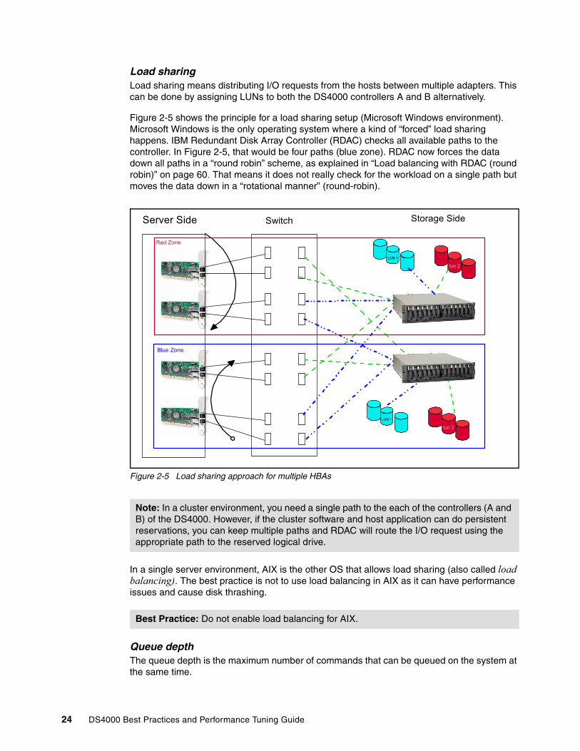
Load sharingLoad sharing means distributing I/O requests from the hosts between multiple adapters. This can be done by assigning LUNs to both the DS4000 controllers A and B alternatively.
Figure 2-5 shows the principle for a load sharing setup (Microsoft Windows environment). Microsoft Windows is the only operating system where a kind of “forced” load sharing happens. IBM Redundant Disk Array Controller (RDAC) checks all available paths to the controller. In Figure 2-5, that would be four paths (blue zone). RDAC now forces the data down all paths in a “round robin” scheme, as explained in “Load balancing with RDAC (round robin)” on page 60. That means it does not really check for the workload on a single path but moves the data down in a “rotational manner” (round-robin).
Figure 2-5 Load sharing approach for multiple HBAs
In a single server environment, AIX is the other OS that allows load sharing (also called load balancing). The best practice is not to use load balancing in AIX as it can have performance issues and cause disk thrashing.
Queue depthThe queue depth is the maximum number of commands that can be queued on the system at the same time.
Note: In a cluster environment, you need a single path to the each of the controllers (A and B) of the DS4000. However, if the cluster software and host application can do persistent reservations, you can keep multiple paths and RDAC will route the I/O request using the appropriate path to the reserved logical drive.
Best Practice: Do not enable load balancing for AIX.
Server Side Switch Storage Side
LUN 1
lun 2
LUN 1
lun 2
Red Zone
Blue Zone
24 DS4000 Best Practices and Performance Tuning Guide

The DS4000 controller firmware version 05.30.xx.xx or earlier, the queue depth is 512; for the DS4000 controller firmware versions 06.1x.xx.xx or 05.4x.xx.xx, the queue depth is 2048. This is represents 1024 per controller.
The formula for the correct queue depth on the host HBA for this level of firmware code is:
2048 / (number of hosts * LUNs per host)
For example, a system with four hosts, each with 32 LUNs, would have a maximum queue depth of 16: 2048 / (4 * 32) = 16.
This setting should be set on each host bus adapter. See also 4.3.1, “Host based settings” on page 116.
For Qlogic based HBAs the queue depth is known as execution throttle, this can be set with either FAStT MSJ or in the BIOS of the Qlogic based HBA by pressing CTL+Q during the boot process.
2.2.5 Disk expansion enclosures The DS4000 Series offers two expansion enclosures, the EXP710 Fibre enclosure, and the EXP100 SATA enclosure. When planning for switch enclosure to use with your DS4000, you must look at the applications and data that you will be using on the DS4000. The EXP 710 offers higher performance than the EXP100, due to the speed of the disks that the enclosure can use. The EXP 100 enclosure is a lower cost option with lower performance.
Enclosure IDsIt is very important to correctly set the tray (enclosure) ID switches on ESM boards. They are used to differentiate multiple EXP Enclosures that are connected to the same DS4000 Storage Server. Each EXP Enclosure must use a unique value. The DS4000 Storage Manager uses the tray IDs to identify each EXP Enclosure. Additionally, the Fibre Channel Fabric Address (EXP100/EXP710) for each disk drive is automatically set according to:
� The EXP710 bay where the disk drive is inserted� Tray ID setting
Two switches are available to set the tray ID:
� A switch for tens (x10)� A switch for ones (x1)
We can therefore set any number between 0 and 99. See Figure 2-6.
Enclosure guidelinesBecause the storage system follows a specific address assignment scheme for the drives, you should observe a few guidelines when assigning enclosure IDs to expansion units. Failure to adhere to these guidelines can cause issues with I/O error recovery, and make more difficult the troubleshooting of certain drive communication issues:
� Limit the number of expansion units to eight for each drive loop pair.
� Do not use enclosure ID from 00 through 09.
Important: Every EXP attached to the same DS4000 subsystem must have a different enclosure ID. If the DS4000 Storage Server has internal HDDs (such as the DS4300), the EXP attached to it should be set to a different tray ID, otherwise, the front panel of both DS4000 Storage Server and EXP will have an Amber LED.
Chapter 2. DS4000 planning tasks 25

� Ensure that the least significant digit (units) of the enclosure ID is unique within a drive loop pair. The most significant digit (tens) should be unique for each loop pair of a given Storage Subsystem. For instance, a loop of purely EXP710’s should be numbered 10–17 for the first loop pair and 20–27 for the second loop pair.
� Whenever possible, maintain an even number of expansion units on the DS4000 server and configure for enclosure loss protection. Add EXP expansion units in pairs and (ideally) for the DS4800 in groups of four.
� Add drives into an expansion enclosure in pairs.
Figure 2-6 Enclosure ID
� Avoid fully populating all expansion units.
Once the DS4000 is fully populated with the maximum number of enclosures and drives, there is simply no more expansion possible. As the requirement increases for the numbers of drives, perhaps it is time to look at an additional DS4000 storage system or storage virtualization or even both.
Plan on upgrading EXP700 to EXP710For all current installations, we recommend upgrading any EXP700 to an EXP710. Note also that the DS4800 requires EXP710s and does not support EXP700s.
The EXP700 to EXP710 upgrade consists of replacing the EXP700 ESM modules (two on each EXP unit) with EXP710 SBOD (switched) ESM modules. This operation can be done either without an outage (hot) or with an outage (cold). Upgrading to EXP710s allows you to reap the benefits of additional availability, boosted performance in high I/O environments, and more powerful diagnostic abilities. Other than the ESMs, the other EXP components remain the same. See Figure 2-7.
Best Practice: Plan on using no more than 80% of the maximum possible capacity for the DS4000 system.
26 DS4000 Best Practices and Performance Tuning Guide

Figure 2-7 Upgrading an EXP700 to EXP710 - ESM Boards
More detailed information about this procedure can be found in the redbook, IBM TotalStorage DS4000 Series and Storage Manager, SG24-7010.
You can also consult the IBM support Web site for additional information on this upgrade:
http://www.ibm.com/servers/storage/support/disk/exp710/
2.2.6 Selecting drivesThe speed and the type of the drives used will impact the performance. Typically the faster the drive, the higher the performance. This increase in performance comes at a cost, the faster drives are typically a higher cost than the lower performance drives. FC drives outperform the SATA drives.
The DS4000 supports both Fibre Channel and SATA drives. To use SATA drives in your DS4000, an EXP100 expansion cabinet is required for all models but the DS4100. If Fibre Channel drives are used as well, the FC/SATA Intermix Premium Feature is required and is an additional cost.
The following types of FC drives are currently available:
� 36 GB, 73 GB, 146 GB and 300 GB drives at 10K RPM.� 18 GB, 36 GB, 73 GB and 146 GB drives at 15KRPM.
At the time of writing this book, a SATA drive with a capacity of 400 GB at 7200 RPM was just announced and replaces the former 250 GB drive.
Important: It is critical that you carefully follow the specific upgrade directions from IBM when upgrading from EXP700 to EXP710. There are firmware upgrades (ESM, controller, NVSRAM, drive) that must be done precisely and in the correct sequence before actually replacing the physical EXP700 ESMs with EXP710 ESMs.
Not strictly following these directions could result in data loss.
Chapter 2. DS4000 planning tasks 27

Table 2-2 compares the Fibre Channel 10K, 15K and SATA drives (single drive).
Table 2-2 Comparison between Fibre Channel and SATA
The speed of the drive is the number or revolutions per minute (RPM). A 15K drive rotates 15,000 times per minute. With the higher speeds the drives tend to be denser, as a large diameter plate driving at such speeds is likely to wobble. With the faster speeds comes the ability to have greater throughput.
Seek time is the measure of how long it takes for the drive head to move to the correct sectors on the drive to either read or write data. It is measured in thousands of a second (milliseconds or ms). The faster the seek time, the quicker data can be read from or written to the drive. The average seek time reduces when the speed of the drive increases. Typically a 7.2K will have an average seek time of around 9ms, a 10K drive will have an average seek time of around 5.5ms, and a 15Kdrive will have an average seek time of around 3.5ms.
Note: The usable disk space is less than overall disk capacity. Please note the usable capacity amounts for storage capacity calculation issues:
� 18.2 GB formatted capacity is equal to 16.450 GB usable capacity.� 36.4 GB formatted capacity is equal to 33.400 GB usable capacity.� 73.4 GB formatted capacity is equal to 67.860 GB usable capacity.� 146.8 GB formatted capacity is equal to 136.219 GB usable capacity.� 300 GB formatted capacity is equal to 278.897 GB usable capacity.
The usable capacities are what the SMclient will report as storage that can be used by the hosts. We arrive at this number by the following steps:
1. Take the listed raw disk amount (listed in decimal, as the storage industry standard dictates) and divide by 1.073742 to get a raw binary capacity (1 decimal GB = 1,000,000,000 bytes; 1 binary GB = 1,073,741,824 bytes (2^30 bytes)).
2. Subtract out the 512 MB DACstore region (the region that holds configuration information) after converting the DACstore to binary.
This will give you the usable binary capacity that can be utilized by hosts and is what the SMclient will report to you as usable capacity.
Best Practice: Use the fastest drives available for best performance.
Fibre Channel SATA SATA difference
Spin Speed 10K and 15K 7.2K
Command Queuing Yes16 Max
No1 Max
Single Disk IO Rate (# of 512 bytes IOPS)a
a. Note that the IOPS and bandwidth figures are from disk manufacturer tests in ideal lab conditions. In practice you will see lower numbers, but the ratio between SATA and FC disks still applies.
280 & 340 88 .31 & .25
Read Bandwidth (MB/s)
69 & 76 60 .86 & .78
Write Bandwidth (MB/s)
68 & 71 30 .44
28 DS4000 Best Practices and Performance Tuning Guide

Command queuing allows for multiple commands to be outstanding to the disk drive at the same time. The drives have a queue where outstanding commands can be dynamically rescheduled or re-ordered, along with the necessary tracking mechanisms for outstanding and completed portions of workload. The SATA disks do not have command queuing and the Fibre Channel disks currently have a command queue depth of 16.
Avoid using the SATA drives for high IOPS operations. SATA can however, be used for streaming and archiving applications. These are both very good uses for SATA, where good throughput rates are required, but at a lower cost.
2.3 Planning your storage structure It is important to configure a storage system in accordance to the needs of the user. An important question and primary concern for most users or storage administrators is how to configure the storage subsystem to achieve best for the best performance. There is no simple answer, no best guideline for storage performance optimization that is valid in every environment and for every particular situation. We have dedicated a chapter of this book (see Chapter 4, “DS4000 performance tuning” on page 113) to discuss and recommend how to configure or tune the various components and features of the DS4000 to achieve the best performance upon different circumstances. You will find some preliminary (and less detailed) performance discussion in this section.
Also, in this section, we review other aspects of the system configuration that can help optimize the storage capacity and resilience of the system. In particular, we review and discuss the RAID levels, array size, array configuration, and enclosure loss protection.
2.3.1 Arrays and RAID levelsAn array is a set of drives that the system logically groups together to provide one or more logical drives to an application host or cluster.
When defining arrays, you often have to compromise among capacity, performance, and redundancy.
RAID levelsWe go through the different RAID levels and explain why we would choose this particular setting in this particular situation, and then you can draw your own conclusions. See also “RAID array types” on page 136.
RAID-0: For performance, but generally not recommendedRAID-0 (refer to Example 2-8) is also known as data striping. It is well-suited for program libraries requiring rapid loading of large tables, or more generally, applications requiring fast access to read-only data or fast writing. RAID-0 is only designed to increase performance. There is no redundancy, so any disk failures require reloading from backups. Select RAID level 0 for applications that would benefit from the increased performance capabilities of this RAID level. Never use this level for critical applications that require high availability.
Note: Topics introduced in this section are also discussed from a performance optimization perspective in Chapter 4, “DS4000 performance tuning” on page 113.
Chapter 2. DS4000 planning tasks 29

Figure 2-8 RAID 0
RAID-1: For availability/good read response timeRAID-1 (refer to Example 2-9) is also known as disk mirroring. It is most suited to applications that require high data availability, good read response times, and where cost is a secondary issue. The response time for writes can be somewhat slower than for a single disk, depending on the write policy. The writes can either be executed in parallel for speed or serially for safety. Select RAID level 1 for applications with a high percentage of read operations and where the cost is not the major concern.
Because the data is mirrored, the capacity of the logical drive when assigned RAID level 1 is 50% of the array capacity.
Figure 2-9 RAID 1
etc.Block 3Block 0Disk 1
etc.Block 4Block 1Disk 2
etc.Block 5Block 2Disk 3
etc.Block 5Block 4Block 3Block 2Block 1Block 0
Logical Drive
Actualdevice
mappings
Stripeset
Host view
etc.Block 2Block 1Block 0
Logical Drive
Actualdevice
mappings
etc.Block 2Block 1Block 0Disk 1
etc.Block 2Block 1Block 0Disk 2
Mirrorset
Host view
30 DS4000 Best Practices and Performance Tuning Guide

Here are some recommendations when using RAID-1:
� Use RAID-1 for the disks that contain your operating system. It is a good choice, because the operating system can usually fit on one disk.
� Use RAID-1 for transaction logs. Typically, the database server transaction log can fit on one disk drive. In addition, the transaction log performs mostly sequential writes. Only rollback operations cause reads from the transaction logs. Therefore, we can achieve a high rate of performance by isolating the transaction log on its own RAID-1 array.
� Use write caching on RAID-1 arrays. Because a RAID-1 write will not complete until both writes have been done (two disks), performance of writes can be improved through the use of a write cache. When using a write cache, be sure it is battery-backed up.
RAID-3: Sequential access to large filesRAID-3 is a parallel process array mechanism, where all drives in the array operate in unison. Similar to data striping, information to be written to disk is split into chunks (a fixed amount of data), and each chunk is written out to the same physical position on separate disks (in parallel). This architecture requires parity information to be written for each stripe of data.
Performance is very good for large amounts of data, but poor for small requests because every drive is always involved, and there can be no overlapped or independent operation. It is well-suited for large data objects such as CAD/CAM or image files, or applications requiring sequential access to large data files. Select RAID-3 for applications that process large blocks of data. It provides redundancy without the high overhead incurred by mirroring in RAID-1.
RAID-5: High availability and fewer writes than readsRAID level 5 (refer to Figure 2-10) stripes data and parity across all drives in the array. RAID level 5 offers both data protection and increased throughput. When you assign RAID-5 to an array, the capacity of the array is reduced by the capacity of one drive (for data-parity storage). RAID-5 gives you higher capacity than RAID-1, but RAID level 1 offers better performance.
Figure 2-10 RAID 5
Note: RAID 1 is actually implemented only as RAID 10 (described below) on the DS4000 products.
RAIDset
etc.Block 5Block 4Block 3Block 2Block 1Block 0
Logical Drive
Block 15 Block 10Block 5Block 0Disk 1
Parity 12-15
Block 11Block 6Block 1Disk 2
Block 12Parity 8-11
Block 7Block 2Disk 3
Block 13
Block 8Parity 4-7Block 3Disk 4
Block 14Block 9Block 4
Parity 0-3Disk 5
Host View
Chapter 2. DS4000 planning tasks 31
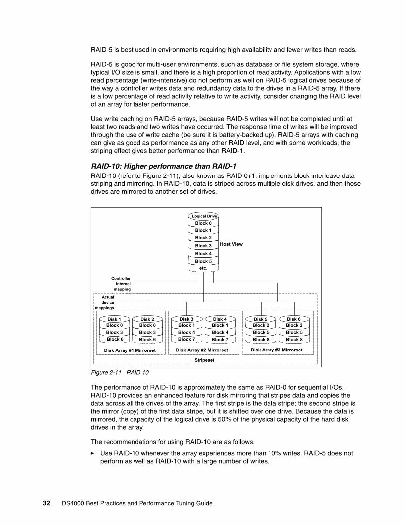
RAID-5 is best used in environments requiring high availability and fewer writes than reads.
RAID-5 is good for multi-user environments, such as database or file system storage, where typical I/O size is small, and there is a high proportion of read activity. Applications with a low read percentage (write-intensive) do not perform as well on RAID-5 logical drives because of the way a controller writes data and redundancy data to the drives in a RAID-5 array. If there is a low percentage of read activity relative to write activity, consider changing the RAID level of an array for faster performance.
Use write caching on RAID-5 arrays, because RAID-5 writes will not be completed until at least two reads and two writes have occurred. The response time of writes will be improved through the use of write cache (be sure it is battery-backed up). RAID-5 arrays with caching can give as good as performance as any other RAID level, and with some workloads, the striping effect gives better performance than RAID-1.
RAID-10: Higher performance than RAID-1RAID-10 (refer to Figure 2-11), also known as RAID 0+1, implements block interleave data striping and mirroring. In RAID-10, data is striped across multiple disk drives, and then those drives are mirrored to another set of drives.
Figure 2-11 RAID 10
The performance of RAID-10 is approximately the same as RAID-0 for sequential I/Os. RAID-10 provides an enhanced feature for disk mirroring that stripes data and copies the data across all the drives of the array. The first stripe is the data stripe; the second stripe is the mirror (copy) of the first data stripe, but it is shifted over one drive. Because the data is mirrored, the capacity of the logical drive is 50% of the physical capacity of the hard disk drives in the array.
The recommendations for using RAID-10 are as follows:
� Use RAID-10 whenever the array experiences more than 10% writes. RAID-5 does not perform as well as RAID-10 with a large number of writes.
Stripeset
etc.Block 5Block 4Block 3Block 2Block 1Block 0
Logical Drive
Host View
Controllerinternal
mapping
Actualdevice
mappings
Block 6Block 3Block 0Disk 1
Block 6Block 3Block 0Disk 2
Block 7Block 4Block 1Disk 3
Block 7Block 4Block 1Disk 4
Block 8Block 5Block 2Disk 5
Block 8Block 5Block 2Disk 6
Disk Array #1 Mirrorset Disk Array #2 Mirrorset Disk Array #3 Mirrorset
32 DS4000 Best Practices and Performance Tuning Guide

� Use RAID-10 when performance is critical. Use write caching on RAID-10. Because a RAID-10 write will not be completed until both writes have been done, write performance can be improved through the use of a write cache (be sure it is battery-backed up).
When comparing RAID-10 to RAID-5:
� RAID-10 writes a single block through two writes. RAID-5 requires two reads (read original data and parity) and two writes. Random writes are significantly faster on RAID-10.
� RAID-10 rebuilds take less time than RAID-5 rebuilds. If a real disk fails, RAID-10 rebuilds it by copying all the data on the mirrored disk to a spare. RAID-5 rebuilds a failed disk by merging the contents of the surviving disks in an array and writing the result to a spare.
RAID-10 is the best fault-tolerant solution in terms of protection and performance, but it comes at a cost. You must purchase twice the number of disks that are necessary with RAID-0.
The following note and Table 2-3 summarize this information.
Table 2-3 RAID levels comparison
Summary: Based on the respective level, RAID offers the following performance results:
� RAID-0 offers high performance, but does not provide any data redundancy.
� RAID-1 offers high performance for write-intensive applications.
� RAID-3 is good for large data transfers in applications, such as multimedia or medical imaging, that write and read large sequential chunks of data.
� RAID-5 is good for multi-user environments, such as database or file system storage, where the typical I/O size is small, and there is a high proportion of read activity.
� RAID-10 offers higher performance than RAID-1 and more reliability than RAID-5
RAID Description APP Advantage Disadvantage
0 Stripes data across multiple drives.
IOPS Mbps
Performance due to parallel operation of the access.
No redundancy. One drive fails, data is lost.
1 Disk's data is mirrored to another drive.
IOPS Performance as multiple requests can be fulfilled simultaneously.
Storage costs are doubled.
10 Data is striped across multiple drives and mirrored to same number of disks.
IOPS Performance as multiple requests can be fulfilled simultaneously. Most reliable RAID level on the DS4000
Storage costs are doubled.
3 Drives operated independently with data blocks distributed among all drives. Parity is written to a dedicated drive.
Mbps High performance for large, sequentially accessed files (image, video, graphical).
Degraded performance with 8-9 I/O threads, random IOPS, smaller more numerous IOPS.
5 Drives operated independently with data and parity blocks distributed across all drives in the group.
IOPSMbps
Good for reads, small IOPS, many concurrent IOPS and random I/Os.
Writes are particularly demanding.
Chapter 2. DS4000 planning tasks 33

RAID reliability considerationsAt first glance both RAID-3 and RAID-5 would appear to provide excellent protection against drive failure. With today’s high-reliability drives, it would appear unlikely that a second drive in an array would fail (causing data loss) before an initial failed drive could be replaced.
However, field experience has shown that when a RAID-3 or RAID-5 array fails, it is not usually due to two drives in the array experiencing complete failure. Instead, most failures are caused by one drive going bad, and a single block somewhere else in the array that cannot be read reliably.
This problem is exacerbated by using large arrays with RAID-5. This stripe kill can lead to data loss when the information to re-build the stripe is not available. The end effect of this issue will of course depend on the type of data and how sensitive it is to corruption. While most storage subsystems (including the DS4000) have mechanisms in place to try to prevent this from happening, they cannot work 100% of the time.
Any selection of RAID type should take into account the cost of downtime. Simple math tells us that RAID-3 and RAID-5 are going to suffer from failures more often than RAID 10. (Exactly how often is subject to many variables and is beyond the scope of this book.) The money saved by economizing on drives can be easily overwhelmed by the business cost of a crucial application going down until it can be restored from backup.
Naturally, no data protection method is hundred percent reliable, and even if RAID were faultless, it would not protect your data from accidental corruption or deletion by program error or operator error. Therefore, all crucial data should be backed up by appropriate software, according to business needs.
Table 2-4 RAID level and performance
Array sizeMaximum array size has an upper limit of 30 disks. This figure is unrealistic in all but the DS4800. For the DS4100, DS4300, and DS4500, the best performance for number of disks in an array is around 10 disks.
Raw space means the total space available on your disk. Depending on your RAID level, the usable space will be between 50% for RAID-1 and (N- 1)* drive capacity, where N is the number of drives for RAID-5.
RAID levels Data capacitya
Sequential I/O performanceb Random I/O performanceb
Read Write Read Write
Single disk n 6 6 4 4
RAID-0 n 10 10 10 10
RAID-1 n/2 7 5 6 3
RAID-5 n-1 7 7c 7 4
RAID-10 n/2 10 9 7 6
a. In the data capacity, n refers to the number of equally sized disks in the array.b. 10 = best, 1 = worst. We should only compare values within each column. Comparisons between columns are not valid for this table.c. With the write back setting enabled.
Important: The maximum size of a logical drive (LUN) is 2 TB.
34 DS4000 Best Practices and Performance Tuning Guide
DACstorThe DACStor is a reserved area on each disk of the DS4000 Storage Server. This reserved area contains information about drives and other information needed by the controller. The DACStor is approximately 512Mb in size on each disk. This size may grow as future enhancements are made to the firmware. It is always a good idea to leave some free space inside every array to cater for any future increase in the DACstor size.
Array configurationBefore you can start using the physical disk space, you must configure it. That is, you divide your (physical) disk drives into arrays and create one or more logical drives inside each array.
In simple configurations, you can use all of your drive capacity with just one array and create all of your logical drives in that unique array. However, this presents the following drawbacks:
� If you experience a (physical) drive failure, the rebuild process affects all logical drives, and the overall system performance goes down.
� Read/write operations to different logical drives are still being made to the same set of physical hard drives.
� There could be changes to future DACstor size.
The array configuration is crucial to performance. You must take into account all the logical drives inside the array, as all logical drives inside the array will impact on the same physical disks. If you have two logical drives inside and array and they both are high throughput, then there may be contention for access to the physical drives as large read or write requests are serviced. It is crucial to know the type of data that each logical drive is used for and try to balance the load so contention for the physical drives is minimized. Contention is impossible to eliminate unless the array only contains one logical drive.
Number of drivesThe more physical drives you have per array, the shorter the access time for read and write I/O operations. See also “Number of disks per array” on page 137.
You can determine how many physical drives should be associated with a RAID controller by looking at disk transfer rates (rather than at the megabytes per second). For example, if a hard disk drive is capable of 75 nonsequential (random) I/Os per second, about 26 hard disk drives working together could, theoretically, produce 2000 nonsequential I/Os per second, or enough to hit the maximum I/O handling capacity of a single RAID controller. If the hard disk drive can sustain 150 sequential I/Os per second, it takes only about 13 hard disk drives working together to produce the same 2000 sequential I/Os per second and keep the RAID controller running at maximum throughput.
Tip: The first rule for the successful building of good performing storage solutions is to have enough physical space to create the arrays and logical drives as required.
Best Practice: Always leave a small amount of free space on each array to allow for expansion of logical drives, changes in DACstor size, or for premium copy features.
Chapter 2. DS4000 planning tasks 35

Enclosure loss protection planningEnclosure loss protection is a good way to make your system more resilient against hardware failures. Enclosure loss protection means that you spread your protection arrays across multiple enclosures rather than in one enclosure so that a failure of a single enclosure does not take a whole array offline.
By default, the automatic configuration is enabled. However, this is not the best practice as the method of creating arrays. Instead, use the manual method, as this allows for more configuration options to be available at creation time.
See 3.2.2, “DS4100 and DS4300 drive expansion cabling” on page 72 for instructions on how to proceed.
Figure 2-12 shows an example of the enclosure loss protection. If enclosure number 2 were to fail, the array with the enclosure loss protection would still function (granted in a degraded state), but it would still function, as the other drives are not affected by the failure.
Figure 2-12 Enclosure loss protection
Tip: Having more physical disks for the same overall capacity gives you:
� Performance: By doubling the number of the physical drives, you can expect up to a 50% increase in throughput performance.
� Flexibility: Using more physical drives gives you more flexibility to build arrays and logical drives according to your needs.
� Data capacity: When using RAID-5 logical drives, more data space is available with smaller physical drives because less space (capacity of a drive) is used for parity.
Best Practice: Manual array configuration allows for greater control over the creation of arrays.
36 DS4000 Best Practices and Performance Tuning Guide
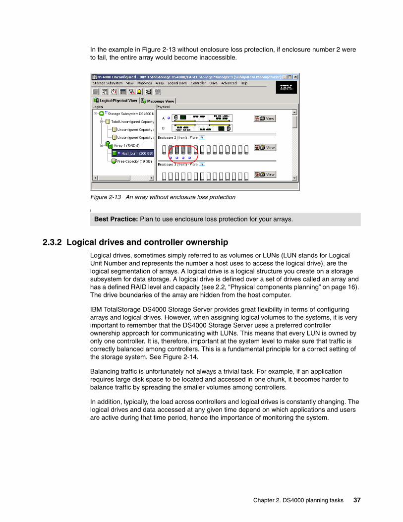
In the example in Figure 2-13 without enclosure loss protection, if enclosure number 2 were to fail, the entire array would become inaccessible.
Figure 2-13 An array without enclosure loss protection
I
2.3.2 Logical drives and controller ownershipLogical drives, sometimes simply referred to as volumes or LUNs (LUN stands for Logical Unit Number and represents the number a host uses to access the logical drive), are the logical segmentation of arrays. A logical drive is a logical structure you create on a storage subsystem for data storage. A logical drive is defined over a set of drives called an array and has a defined RAID level and capacity (see 2.2, “Physical components planning” on page 16). The drive boundaries of the array are hidden from the host computer.
IBM TotalStorage DS4000 Storage Server provides great flexibility in terms of configuring arrays and logical drives. However, when assigning logical volumes to the systems, it is very important to remember that the DS4000 Storage Server uses a preferred controller ownership approach for communicating with LUNs. This means that every LUN is owned by only one controller. It is, therefore, important at the system level to make sure that traffic is correctly balanced among controllers. This is a fundamental principle for a correct setting of the storage system. See Figure 2-14.
Balancing traffic is unfortunately not always a trivial task. For example, if an application requires large disk space to be located and accessed in one chunk, it becomes harder to balance traffic by spreading the smaller volumes among controllers.
In addition, typically, the load across controllers and logical drives is constantly changing. The logical drives and data accessed at any given time depend on which applications and users are active during that time period, hence the importance of monitoring the system.
Best Practice: Plan to use enclosure loss protection for your arrays.
Chapter 2. DS4000 planning tasks 37
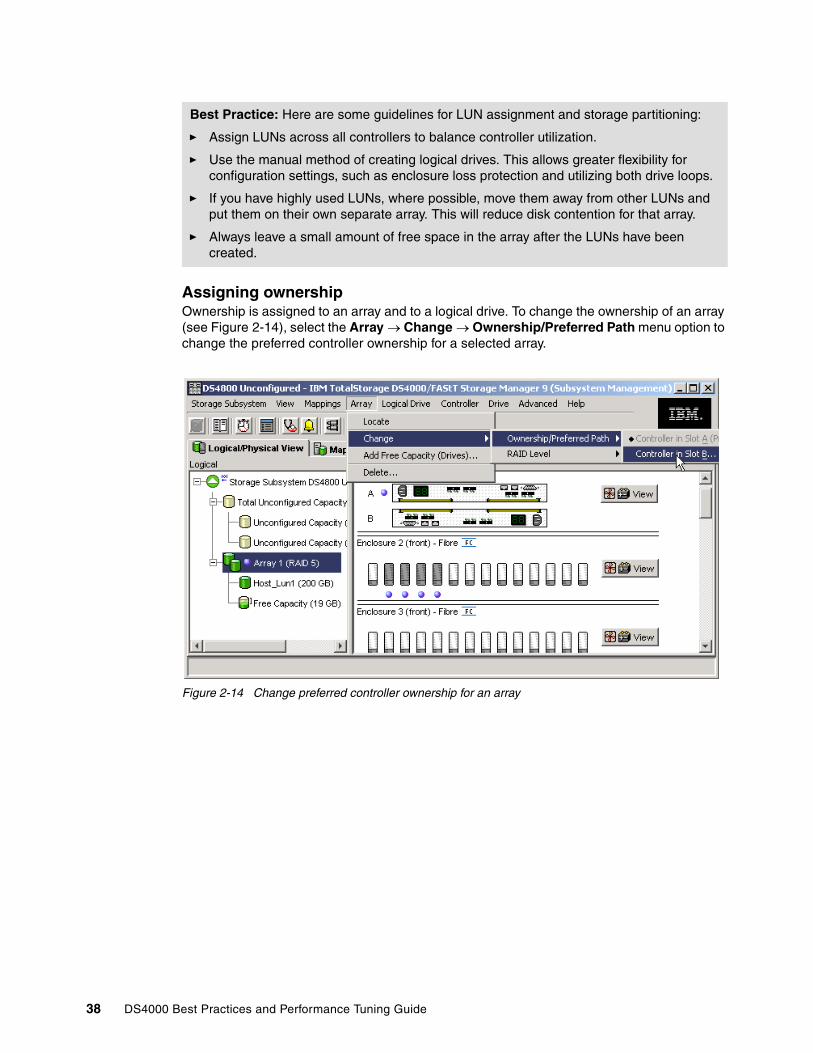
Assigning ownershipOwnership is assigned to an array and to a logical drive. To change the ownership of an array (see Figure 2-14), select the Array → Change → Ownership/Preferred Path menu option to change the preferred controller ownership for a selected array.
Figure 2-14 Change preferred controller ownership for an array
Best Practice: Here are some guidelines for LUN assignment and storage partitioning:
� Assign LUNs across all controllers to balance controller utilization.
� Use the manual method of creating logical drives. This allows greater flexibility for configuration settings, such as enclosure loss protection and utilizing both drive loops.
� If you have highly used LUNs, where possible, move them away from other LUNs and put them on their own separate array. This will reduce disk contention for that array.
� Always leave a small amount of free space in the array after the LUNs have been created.
38 DS4000 Best Practices and Performance Tuning Guide
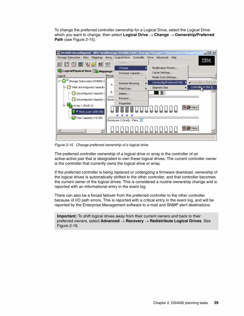
To change the preferred controller ownership for a Logical Drive, select the Logical Drive which you want to change, then select Logical Drive → Change → Ownership/Preferred Path (see Figure 2-15).
Figure 2-15 Change preferred ownership of a logical drive
The preferred controller ownership of a logical drive or array is the controller of an active-active pair that is designated to own these logical drives. The current controller owner is the controller that currently owns the logical drive or array.
If the preferred controller is being replaced or undergoing a firmware download, ownership of the logical drives is automatically shifted to the other controller, and that controller becomes the current owner of the logical drives. This is considered a routine ownership change and is reported with an informational entry in the event log.
There can also be a forced failover from the preferred controller to the other controller because of I/O path errors. This is reported with a critical entry in the event log, and will be reported by the Enterprise Management software to e-mail and SNMP alert destinations.
Important: To shift logical drives away from their current owners and back to their preferred owners, select Advanced → Recovery → Redistribute Logical Drives. See Figure 2-16.
Chapter 2. DS4000 planning tasks 39
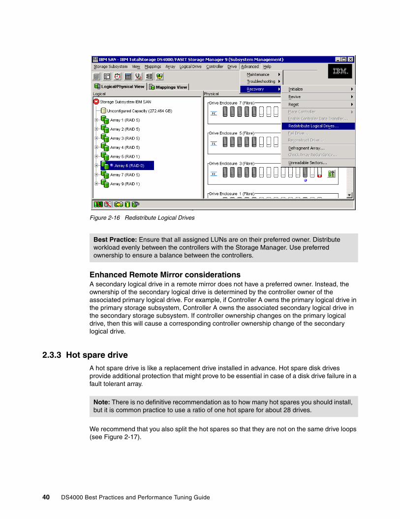
Figure 2-16 Redistribute Logical Drives
Enhanced Remote Mirror considerationsA secondary logical drive in a remote mirror does not have a preferred owner. Instead, the ownership of the secondary logical drive is determined by the controller owner of the associated primary logical drive. For example, if Controller A owns the primary logical drive in the primary storage subsystem, Controller A owns the associated secondary logical drive in the secondary storage subsystem. If controller ownership changes on the primary logical drive, then this will cause a corresponding controller ownership change of the secondary logical drive.
2.3.3 Hot spare drive A hot spare drive is like a replacement drive installed in advance. Hot spare disk drives provide additional protection that might prove to be essential in case of a disk drive failure in a fault tolerant array.
We recommend that you also split the hot spares so that they are not on the same drive loops (see Figure 2-17).
Best Practice: Ensure that all assigned LUNs are on their preferred owner. Distribute workload evenly between the controllers with the Storage Manager. Use preferred ownership to ensure a balance between the controllers.
Note: There is no definitive recommendation as to how many hot spares you should install, but it is common practice to use a ratio of one hot spare for about 28 drives.
40 DS4000 Best Practices and Performance Tuning Guide

Figure 2-17 Hot spare coverage with alternating loops
2.3.4 Storage partitioning
Storage partitioning adds a high level of flexibility to the DS4000 Storage Server. It enables you to connect to the same storage server multiple and heterogeneous host systems, either in stand-alone or clustered mode. The term storage partitioning is somewhat misleading, as it actually represents a host or a group of hosts and the logical disks they access.
Without storage partitioning, the logical drives configured on a DS4000 Storage Server can only be accessed by a single host system or by a single cluster. This can lead to inefficient use of the storage server hardware.
With storage partitioning, on the other hand, you can create sets of objects containing the hosts with their host bus adapters and the logical drives. We call these sets storage partitions. Now, the host systems can only access their assigned logical drives, just as if these logical drives were locally attached to them.
Storage partitioning lets you map and mask LUNs (that is why it is also referred to as LUN masking). That means after you assigned that LUN to a host, it is hidden to all other hosts connected to the same Storage Server. Therefore, the access to that LUN is exclusively reserved for that host.
Best Practice: When assigning disks as hot spares, make sure they have enough storage capacity. If the failed disk drive is larger than the hot spare, reconstruction is not possible. Ensure that you have at least one of each size or all larger drives configured as hot spares.
If you have a mixture of 10K and 15K RPM drives of equal size, it is best practice to ensure that the hot spare is 15K RPM. This will ensure that if a hot spare is used, there is not a performance impact on the array after the rebuild is complete.
Chapter 2. DS4000 planning tasks 41

It is a good practice to do your storage partitioning prior to connecting to multiple hosts. Operating systems such as AIX or Windows 2000 may write their signatures to any device they can access.
Heterogeneous host support means that the host systems can run different operating systems. But be aware that all the host systems within a particular storage partition must run the same operating system, because all host systems within a particular storage partition have unlimited access to all logical drives in this partition. Therefore, file systems on these logical drives must be compatible with host systems. To ensure this, it is best to run the same operating system on all hosts within the same partition. Some operating systems might be able to mount foreign file systems. In addition, Tivoli SANergy® or the IBM SAN File System can enable multiple host operating systems to mount a common file system.
A storage partition contains several components:
� Host groups� Hosts� Host ports� Logical drive mappings
A host group is a collection of hosts that are allowed to access certain logical drives, for example, a cluster of two systems.
A host is a single system that can be mapped to a logical drive.
A host port is the FC port of the host bus adapter in the host system. The host port is identified by its world-wide name (WWN). A single host can contain more than one host port. If you want redundancy then each server needs two host bus adapters. That is, it needs two host ports within the same host system.
In order to do the storage partitioning correctly, you need the WWN of your HBAs. Mapping is done on a WWN basis. Depending on your HBA, you can obtain the WWN either from the BIOS or FAStT MSJ tool if you have Qlogic cards. Emulex adapters and IBM adapters for pSeries and iSeries™ servers have a sticker on the back of the card, as do the JNI and AMCC adapters for Solaris. The WWN is also usually printed on the adapter itself and/or the box the adapter was shipped in.
Note: There are limitations as to how many logical drives you can map per host. DS4000 allows up to 256 LUNs per partition (including the access LUN) and a maximum of two partitions per host. Note that a particular OS platform (refer to the operating system documentation about restrictions) can also impose limitations to the number of LUNs they can support. Keep all these limitations in mind when planning your installation.
Restriction: Most hosts will be able to have 256 LUNs mapped per storage partition. Solaris with RDAC, NetWare 5.x, and HP-UX 11.0 are restricted to 32 LUNs. If you try to map a logical drive to a LUN that is greater than 32 on these operating systems, the host will be unable to access it. Solaris requires use the of Veritas Dynamic Multi-Pathing (DMP) for failover for 256 LUNs.
Netware 6.x with latest support packs and latest multipath driver (LSIMPE.CDM) supports 256 LUNs. Refer to A.3.2, “Notes on Novell Netware 6.x” on page 287 and the latest documentation on the Novell support Web site for further information.
Note: Heterogeneous hosts are only supported with storage partitioning enabled.
42 DS4000 Best Practices and Performance Tuning Guide

If you are connected to a hub or switch, check the Name Server Table of the hub or switch to identify the WWN of the HBAs.
When planning your partitioning, keep in mind that:
� In a cluster environment, you need to use host groups.� You can optionally purchase partitions.
When planning for your storage partitioning, you should create a table of planned partitions and groups so that you can clearly map out and define your environment.
Table 2-5 shows an example of a storage partitioning plan. This clearly shows the host groups, hosts, port names, WWN of the ports, and the operating systems used in that environment. Other columns could be added to the table for future references such as HBA BIOS levels, driver revisions, and switch ports used — all of which can then form the basis of a change control log.
Table 2-5 Sample plan for storage partitioning
Delete the access logical drive – (LUN 31)The DS4000 storage system will automatically create a LUN 31 for each host attached. This is used for in-band management, so if you do not plan to manage the DS4000 storage subsystem from that host, you can delete LUN 31, which will give you one more LUN to use per host.
If you attached a Linux or AIX to the DS4000 storage server, you need to delete the mapping of the access LUN.
Note: If you have to replace a host bus adapter, the WWN of the new adapter will obviously be different. Storage partitioning assignments are based on the WWN. Since the new WWN does not appear in any of the storage partitioning assignments, after replacement, this host system will have no access to any logical drives through this adapter.
Best Practice: If you have a single server in a host group that has one or more LUNs assigned to it, we recommend that you do the mapping to the host and not the host group. All servers having the same host type (for example, Windows servers) can be in the same group if you want, but by mapping the storage at the host level, you can define what specific server accesses which specific LUN.
However, if you have a cluster, it is good practice to assign the LUNs at the host group, so that all of the servers in the host group have access to all the LUNs.
Host group Host name Port name WWN OS type
Windows 2000 Windows Host MailAdp_A 200000E08B28773C Windows 2000 Non-Clustered
MailAdp_B 200000E08B08773C
Linux Linux_Host LinAdp_A 200100E08B27986D Linux
LinAdp_B 200000E08B07986D
RS6000 AIX_Host AIXAdp_A 20000000C926B6D2 AIX
AIXAdp_B 20000000C926B08
Chapter 2. DS4000 planning tasks 43
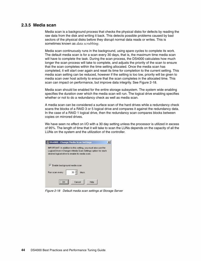
2.3.5 Media scan Media scan is a background process that checks the physical disks for defects by reading the raw data from the disk and writing it back. This detects possible problems caused by bad sectors of the physical disks before they disrupt normal data reads or writes. This is sometimes known as data scrubbing.
Media scan continuously runs in the background, using spare cycles to complete its work. The default media scan is for a scan every 30 days, that is, the maximum time media scan will have to complete the task. During the scan process, the DS4000 calculates how much longer the scan process will take to complete, and adjusts the priority of the scan to ensure that the scan completes within the time setting allocated. Once the media scan has completed, it will start over again and reset its time for completion to the current setting. This media scan setting can be reduced, however if the setting is too low, priority will be given to media scan over host activity to ensure that the scan completes in the allocated time. This scan can impact on performance, but improve data integrity. See Figure 2-18.
Media scan should be enabled for the entire storage subsystem. The system wide enabling specifies the duration over which the media scan will run. The logical drive enabling specifies whether or not to do a redundancy check as well as media scan.
A media scan can be considered a surface scan of the hard drives while a redundancy check scans the blocks of a RAID 3 or 5 logical drive and compares it against the redundancy data. In the case of a RAID 1 logical drive, then the redundancy scan compares blocks between copies on mirrored drives.
We have seen no effect on I/O with a 30 day setting unless the processor is utilized in excess of 95%. The length of time that it will take to scan the LUNs depends on the capacity of all the LUNs on the system and the utilization of the controller.
Figure 2-18 Default media scan settings at Storage Server
44 DS4000 Best Practices and Performance Tuning Guide
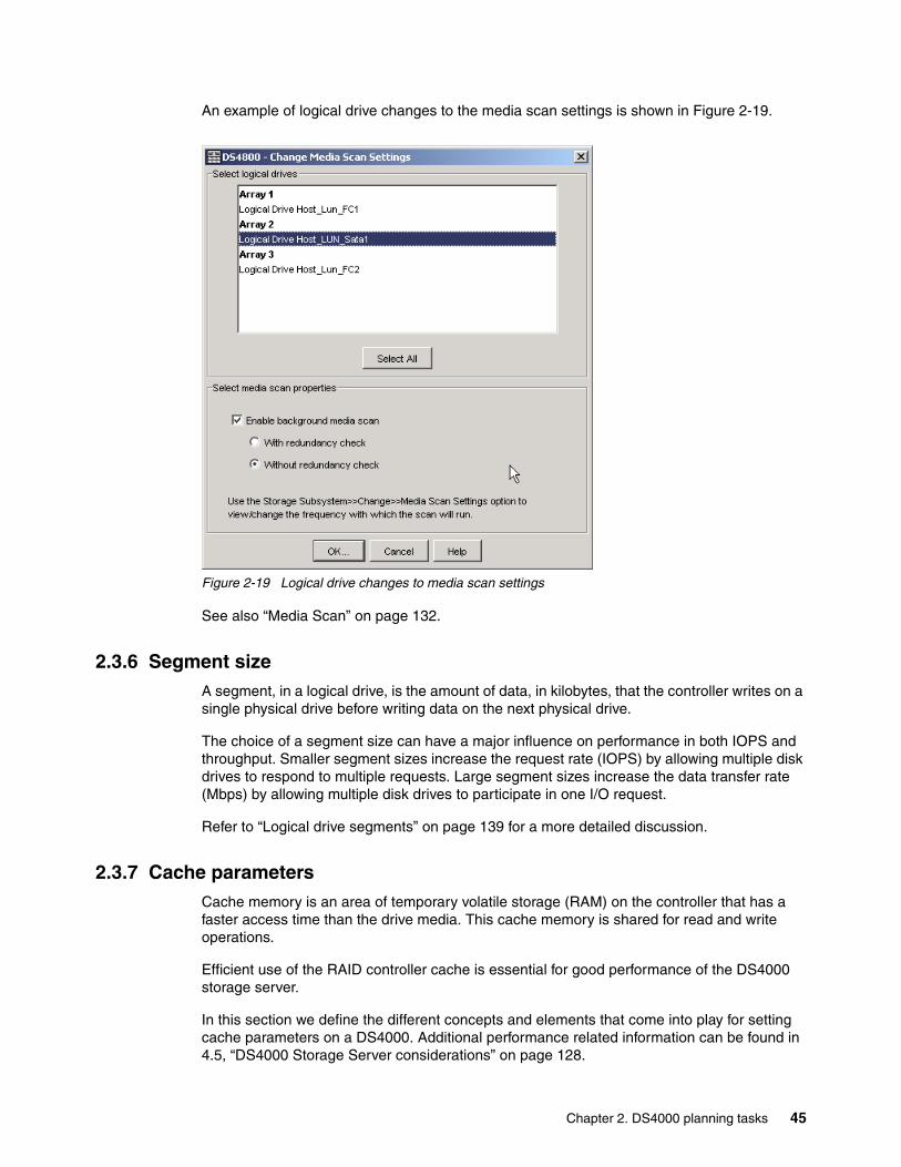
An example of logical drive changes to the media scan settings is shown in Figure 2-19.
Figure 2-19 Logical drive changes to media scan settings
See also “Media Scan” on page 132.
2.3.6 Segment sizeA segment, in a logical drive, is the amount of data, in kilobytes, that the controller writes on a single physical drive before writing data on the next physical drive.
The choice of a segment size can have a major influence on performance in both IOPS and throughput. Smaller segment sizes increase the request rate (IOPS) by allowing multiple disk drives to respond to multiple requests. Large segment sizes increase the data transfer rate (Mbps) by allowing multiple disk drives to participate in one I/O request.
Refer to “Logical drive segments” on page 139 for a more detailed discussion.
2.3.7 Cache parametersCache memory is an area of temporary volatile storage (RAM) on the controller that has a faster access time than the drive media. This cache memory is shared for read and write operations.
Efficient use of the RAID controller cache is essential for good performance of the DS4000 storage server.
In this section we define the different concepts and elements that come into play for setting cache parameters on a DS4000. Additional performance related information can be found in 4.5, “DS4000 Storage Server considerations” on page 128.
Chapter 2. DS4000 planning tasks 45

The diagram shown in Figure 2-20 is a schematic model of the major elements of a disk storage system, elements through which data moves (as opposed to other elements such as power supplies). In the model, these elements are organized into eight vertical layers: four layers of electronic components shown inside the dotted ovals and four layers of paths (that is, wires) connecting adjacent layers of components to each other. Starting at the top in this model, there are some number of host computers (not shown) that connect (over some number of paths) to host adapters. The host adapters connect to cache components. The cache components, in turn, connect to disk adapters that, in turn, connect to disk drives.
Here is how a read I/O request is handled in this model. A host issues a read I/O request that is sent over a path (such as a Fibre Channel) to the disk system. The request is received by a disk system host adapter, which checks whether the requested data is already in cache, in which case, it is immediately sent back to the host. If the data is not in cache, the request is forwarded to a disk adapter that reads the data from the appropriate disk and copies the data into cache. The host adapter sends the data from cache to the requesting host.
Figure 2-20 Conceptual model of disk caching
Most (hardware) RAID controllers have some form of read or write caching, or both. You should plan to take advantage of this caching capabilities, because they enhance the effective I/O capacity of the disk subsystem. The principle of these controller-based caching mechanisms is to gather smaller and potentially nonsequential I/O requests coming in from the host server (for example, SQL Server) and try to batch them with other I/O requests. Consequently, the I/O requests are sent as larger (32 KB to 128 KB) and possibly sequential requests to the hard disk drives. The RAID controller cache arranges incoming I/O requests by making the best use of the hard disks underlying I/O processing ability. This increases the disk I/O throughput.
There are many different settings (related to caching). When implementing a DS4000 Storage Server as part of a whole solution, you should plan at least one week of performance testing and monitoring to adjust the settings.
. . .
. . .
. . .
. . .
. . .
. . .
. . .
. . .
paths to hosts 1...n
1...n
1...n
1...n
1...n
1...n
1...n
1...n
paths to cache
paths to adapters
paths to disks
host adapters
cache
disk adapters
disk drives
46 DS4000 Best Practices and Performance Tuning Guide

The DS4000 Storage Manager utility enables you to configure various cache settings:
Set at the DS4000 system wide settings:
� Start and stop cache flushing levels (this setting will affect all arrays and Logical drives created on the system)
� Cache Block size
Settings per Logical Drive.
� Read caching� Cache read-ahead multiplier� Write caching or write-through mode (write caching disabled)� Enable or disable write cache mirroring
Figure 2-21 shows the typical values when using the Create Logical Drive Wizard. With the Storage Manager, you can specify cache settings for each logical drive independently for more flexibility.
Figure 2-21 Typical values used by the Create Logical Drive Wizard
These settings can have a large impact on the performance of the DS4000 Storage Server and on the availability of data. Be aware that performance and availability often conflict with each other. If you want to achieve maximum performance, in most cases, you must sacrifice system availability and vice versa.
Note: We recommend that you manually set the values during creation to suit the performance needs of the logical drive. These settings can be changed after Logical drive creation for tuning.
Chapter 2. DS4000 planning tasks 47

The default settings are read and write cache for all logical drives, with cache mirroring to the alternate controller for all write data. The write cache is only used if the battery for the controller is fully charged. Read ahead is not normally used on the logical drives.
Read cachingThe read caching parameter can be safely enabled without risking data loss. There are only rare conditions when it is useful to disable this parameter, which then provides more cache for the other logical drives.
Read-ahead multiplier The cache read-ahead multiplier, or prefetch, allows the controller, while it is reading and copying host-requested data blocks from disk into the cache, to copy additional data blocks into the cache. This increases the chance that a future request for data will be fulfilled from the cache. Cache read-ahead is important for multimedia applications that use sequential I/O.
There is a new automatic pre-fetching for the cache read ahead multiplier introduced with Storage Manager 9.1x. This feature is implemented in the firmware and is enabled by specifying any non-zero value for the cache read-ahead multiplier. This will turn on monitoring of the I/O to the logical drive and enable the new algorithm to dynamically choose how much to read ahead. This simplifies the process for the administrator as there is no need to manually set a specific value for the read ahead multiplier, just change the value from zero.
Write cachingThe write caching parameter enables the storage subsystem to cache write data instead of writing it directly to the disks. This can improve performance significantly, especially for environments with random writes such as databases. For sequential writes, the performance gain varies with the size of the data written. If the logical drive is only used for read access, it might improve overall performance to disable the write cache for this logical drive. Then, no cache memory is reserved for this logical drive.
Write cache mirroringDS4000 write cache mirroring provides the integrity of cached data if a RAID controller fails. This is excellent from a high availability perspective, but it decreases performance. The data is mirrored between controllers across the drive-side FC loop. This competes with normal data transfers on the loop. We recommend that you keep the controller write cache mirroring enabled for data integrity reasons in case of a controller failure.
By default, a write cache is always mirrored to the other controller to ensure proper contents, even if the logical drive moves to the other controller. Otherwise, the data of the logical drive can be corrupted if the logical drive is shifted to the other controller and the cache still contains unwritten data. If you turn off this parameter, you risk data loss in the case of a controller failover, which might also be caused by a path failure in your fabric.
The cache of the DS4000 Storage Server is protected, by a battery, against power loss. If the batteries are not fully charged, for example, just after powering on, the controllers automatically disable the write cache. If you enable the parameter, the write cache is used, even if no battery backup is available, resulting in a higher risk of data loss.
Write caching or write-throughWrite-through means that writing operations do not use cache at all. The data is always going to be written directly to the disk drives. Disabling write caching frees up cache for reading (because the cache is shared for read and write operations).
48 DS4000 Best Practices and Performance Tuning Guide

Write caching can increase the performance of write operations. The data is not written straight to the disk drives; it is only written to the cache. From an application perspective, this is much faster than waiting for the disk write operation to complete. Therefore, you can expect a significant gain in application writing performance. It is the responsibility of the cache controller to eventually flush the unwritten cache entries to the disk drives.
Write cache mode appears to be faster than write-through mode, because it increases the performance of both reads and writes. But this is not always true, because it depends on the disk access pattern and workload.
A lightly loaded disk subsystem usually works faster in write-back mode, but when the workload is high, the write cache can become inefficient. As soon as the data is written to the cache, it has to be flushed to the disks in order to make room for new data arriving into cache. The controller would perform faster if the data went directly to the disks. In this case, writing the data to the cache is an unnecessary step that decreases throughput.
Starting and stopping cache flushing levelsThese two settings affect the way the cache controller handles unwritten cache entries. They are only effective when you configure the write-back cache policy. Writing the unwritten cache entries to the disk drives is called flushing. You can configure the start and stop flushing level values. They are expressed as percentages of the entire cache capacity. When the number of unwritten cache entries reaches the start flushing value, the controller begins to flush the cache (write the entries to the disk drives). The flushing stops when the number of unwritten entries drops below the stop flush value. The controller always flushes the oldest cache entries first. Unwritten cache entries older than 20 seconds are flushed automatically.
The default is the start flushing level and the stop flushing level set to 80%. This means the cache controller does not allow more than 80% of the entire cache size for write-back cache, but it also tries to keep as much of it as possible for this purpose. If you use such settings, you can expect a high number of unwritten entries in the cache. This is good for writing performance, but be aware that it offers less data protection.
If the stop level value is significantly lower than the start value, this causes a high amount of disk traffic when flushing the cache. If the values are similar, the controller only flushes the amount needed to stay within limits.
Refer to “Cache flush control settings” on page 134 for further information.
Cache block sizeThis is the size of the cache memory allocation unit and can be either 4 K or 16 K. By selecting the proper value for your particular situation, you can significantly improve the caching efficiency and performance. For example, if applications mostly access the data in small blocks up to 8 K, but you use 16 K for the cache block size, each cache entry block is only partially populated. You always occupy 16 K in cache to store 8 K (or less) of data. This means that only up to 50% of the cache capacity is effectively used to store the data. You can expect lower performance. For random workloads and small data transfer sizes, 4 K is better.
On the other hand, if the workload is sequential, and you use large segment sizes, it is a good idea to use a larger cache block size of 16 K. A larger block size means a lower number of cache blocks and reduces cache overhead delays. In addition, a larger cache block size requires fewer cache data transfers to handle the same amount of data.
Refer to “Cache blocksize selection” on page 134 for further information.
Chapter 2. DS4000 planning tasks 49
2.4 Planning for premium featuresWhen planning for any of the premium features it is a good idea to document what are the goals and rationale for purchasing the feature. This clearly defines from the outset what you want to achieve and why.
Some things that should be considered include:
� Which premium feature to use FlashCopy, VolumeCopy or Enhanced Remote Mirroring� The data size to copy� Additional arrays required� Amount of free space� Number of copies� Retention of copies� Automated or manual copies� Disaster recovery or backup operations
All of the needs and requirements should be documented.
2.4.1 FlashCopyA FlashCopy logical drive is a point-in-time image of a logical drive. It is the logical equivalent of a complete physical copy, but you create it much more quickly than a physical copy. Additionally, it requires less disk space. In DS4000 Storage Manager, the logical drive from which you are basing the FlashCopy, called the base logical drive, must be a standard logical drive in the storage subsystem. Typically, you create a FlashCopy so that an application (for example, an application to take backups) can access the FlashCopy and read the data while the base logical drive remains online and user-accessible.
FlashCopy takes only a small amount of space compared to the base image
For further information regarding FlashCopy, refer to the IBM Redbook, IBM TotalStorage DS4000 Series and Storage Manager, SG24-7010.
2.4.2 VolumeCopy The VolumeCopy feature is a firmware-based mechanism for replicating logical drive data within a storage subsystem. This feature is designed as a system management tool for tasks such as relocating data to other drives for hardware upgrades or performance management, data backup, and restoring snapshot logical drive data.
A VolumeCopy creates a complete physical replication of one logical drive (source) to another (target) within the same storage subsystem. The target logical drive is an exact copy or clone of the source logical drive. VolumeCopy can be used to clone Logical Drives to other arrays inside the DS4000 storage server. Careful planning should considered with regard to space available to make the FlashCopy of a logical drive.
The VolumeCopy premium feature must be enabled by purchasing a Feature Key. For efficient use of VolumeCopy, FlashCopy must be installed as well. VolumeCopy is only available as a bundle which includes a FlashCopy license.
For further information regarding VolumeCopy, refer to the IBM Redbook, IBM TotalStorage DS4000 Series and Storage Manager, SG24-7010.
50 DS4000 Best Practices and Performance Tuning Guide

2.4.3 Enhanced Remote Mirroring (ERM)The Enhanced Remote Mirroring option is a premium feature that comes with the DS4000 Storage Manager Version 9.x software and is enabled by purchasing a premium feature key. The Enhanced Remote Mirroring option is used for online, real-time replication of data between storage subsystems over a remote distance. See Figure 2-22.
Figure 2-22 Enhanced Remote Mirroring
The Enhanced Remote Mirroring is a redesign of the former Remote Volume Mirroring and now offers three different operating modes:
� Metro Mirroring:
Metro Mirroring is a synchronous mirroring mode. Any host write requests are written to the primary (local) storage subsystem and then transferred to the secondary (remote) storage subsystem. The remote storage controller reports the result of the write request operation to the local storage controller which reports it to the host. This mode is called synchronous, because the host application does not get the write request result until the write request has been executed on both (local and remote) storage controllers. This mode corresponds to the former RVM functionality.
� Global Copy:
Global Copy is an asynchronous write mode. All write requests from a host are written to the primary (local) storage subsystem and immediately reported as completed to the host system. Regardless of when data was copied to the remote storage subsystem, the application does not wait for the I/O commit from the remote site. However, Global Copy
SAN FABRIC
NETWORK
V1
StorageServer
V2
V3m
V1m V2m
V3
PRIMARY SITE SECONDARY SITE
Mirroring
Mirroring
StorageServer
Chapter 2. DS4000 planning tasks 51
does not ensure that write requests performed to multiple drives on the primary site are later processed in the same order on the remote site. As such, it is also referred to as Asynchronous Mirroring without Consistency Group.
� Global Mirroring:
Global Mirroring is an asynchronous write that ensures that the write requests are carried out in the same order at the remote site.This mode is also referred to as Asynchronous Mirroring with Consistency Group.
The new Enhanced Remote Mirroring has also been equipped with new functions for better business continuance solution design and maintenance tasks.
A minimum of two storage subsystems is required. One storage subsystem can have primary volumes being mirrored to arrays on other storage subsystems and hold secondary volumes from other storage subsystems. Also note that because replication is managed on a per-logical drive basis, you can mirror individual logical drives in a primary storage subsystem to appropriate secondary logical drives in several different remote storage subsystems.
Planning considerations for Enhanced Remote MirroringHere are some planning considerations:
� DS4000 storage servers (minimum of two)� Fibre links between sites� Distances between sites (ensure that it is supported)� Switches or directors used� Redundancy� Additional storage space requirements
For further information regarding Enhanced Remote Mirroring, refer to the IBM Redbook, IBM TotalStorage DS4000 Series and Storage Manager, SG24-7010.
2.4.4 FC/SATA IntermixIt is now possible to intermix Fibre Channel (FC) and SATA drives in one Storage Server. The flexibility to intermix different drive types (FC and SATA) in one Storage Server gives you the ability to use the advantages of both drive technologies. For example, it is now possible to have the primary (production) storage on FC drives and the secondary (near line or archiving) storage on SATA drives without the need of having different, separate Storage Servers. Or, the FlashCopy or VolumeCopy of an array made of FC drives can be created on cheaper SATA drives.
Note: ERM requires a dedicated “switched fabric” connection per controller to be attached and zoned specific for its use. The dedication is at the following levels:
� DS4100 and DS4300 - Host port 2 on each controller (must be dual controller models)
� DS4400 and DS4500 - Host side minihubs 3 and 4 for A and B controllers with 1 port attached to the switched fabric.
� DS4800 - Host port 4 on both A and B controllers
This dedication is required at both ends of the ERM solution.
52 DS4000 Best Practices and Performance Tuning Guide
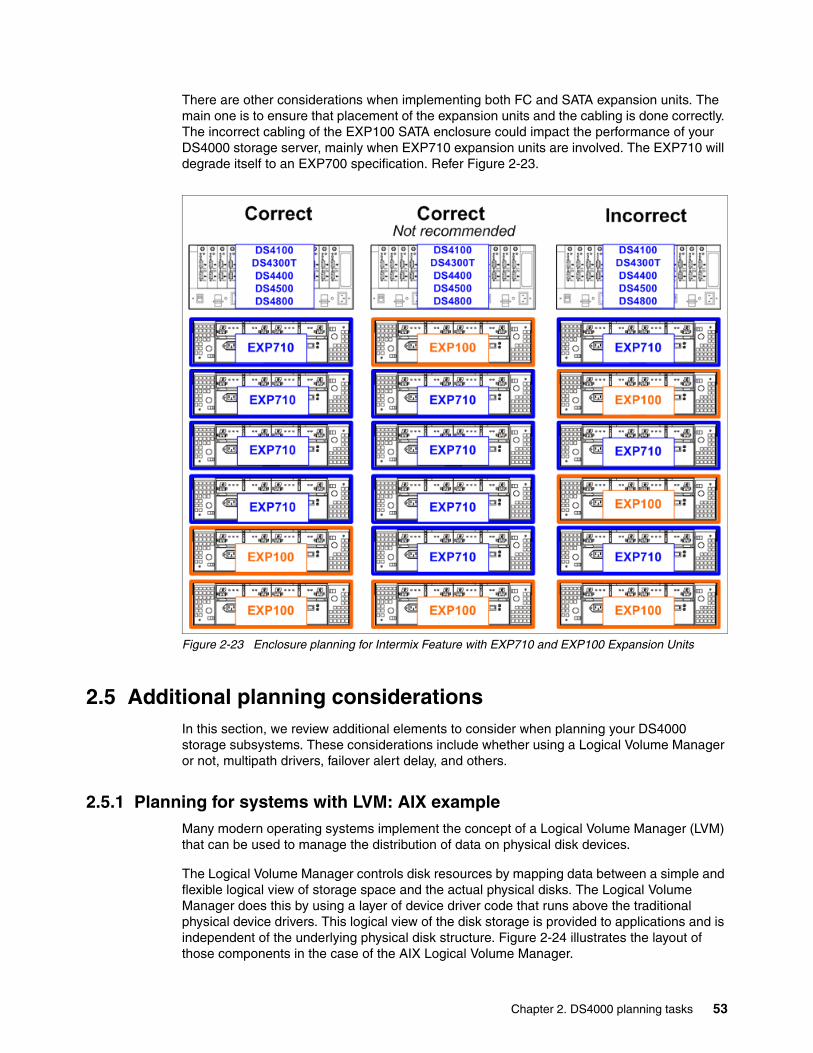
There are other considerations when implementing both FC and SATA expansion units. The main one is to ensure that placement of the expansion units and the cabling is done correctly. The incorrect cabling of the EXP100 SATA enclosure could impact the performance of your DS4000 storage server, mainly when EXP710 expansion units are involved. The EXP710 will degrade itself to an EXP700 specification. Refer Figure 2-23.
Figure 2-23 Enclosure planning for Intermix Feature with EXP710 and EXP100 Expansion Units
2.5 Additional planning considerationsIn this section, we review additional elements to consider when planning your DS4000 storage subsystems. These considerations include whether using a Logical Volume Manager or not, multipath drivers, failover alert delay, and others.
2.5.1 Planning for systems with LVM: AIX exampleMany modern operating systems implement the concept of a Logical Volume Manager (LVM) that can be used to manage the distribution of data on physical disk devices.
The Logical Volume Manager controls disk resources by mapping data between a simple and flexible logical view of storage space and the actual physical disks. The Logical Volume Manager does this by using a layer of device driver code that runs above the traditional physical device drivers. This logical view of the disk storage is provided to applications and is independent of the underlying physical disk structure. Figure 2-24 illustrates the layout of those components in the case of the AIX Logical Volume Manager.
Chapter 2. DS4000 planning tasks 53

Figure 2-24 AIX Logical Volume Manager
A hierarchy of structures is used to manage the actual disk storage, and there is a well defined relationship among these structures.
In AIX, each individual disk drive is called a physical volume (PV) and has a name, usually /dev/hdiskx (where x is a unique integer on the system). In the case of the DS4000 such physical volumes correspond to a LUN.
� Every physical volume in use belongs to a volume group (VG) unless it is being used as a raw storage device.
� Each physical volume is divided into physical partitions (PPs) of a fixed size for that physical volume.
� Within each volume group, one or more logical volumes (LVs) are defined. Logical volumes are groups of information located on physical volumes. Data on logical volumes appear contiguous to the user, but can be spread (striped) on multiple physical volumes.
� Each logical volume consists of one or more logical partitions (LPs). Each logical partition corresponds to at least one physical partition (see Figure 2-25). If mirroring is specified for the logical volume, additional physical partitions are allocated to store the additional copies of each logical partition (with DS4000, this is not recommended, because DS4000 can do the mirroring).
� Logical volumes can serve a number of system purposes (paging, for example), but each logical volume that holds ordinary systems, user data, or programs, contains a single journaled filesystem (JFS or JFS2). Each filesystem consists of a pool of page-size blocks. In AIX Version 4.1 and later, a given filesystem can be defined as having a fragment size of less than 4 KB (512 bytes, 1 KB, 2 KB).
54 DS4000 Best Practices and Performance Tuning Guide

Figure 2-25 Relationships between LP and PP
The Logical Volume Manager controls disk resources by mapping data between a simple and flexible logical view of storage space and the actual physical disks. The Logical Volume Manager does this by using a layer of device driver code that runs above the traditional physical device drivers. This logical view of the disk storage is provided to applications and is independent of the underlying physical disk structure (Figure 2-26).
Figure 2-26 AIX LVM conceptual view
The AIX LVM provides a number of facilities or policies for managing both the performance and availability characteristics of logical volumes. The policies that have the greatest impact on performance in general disk environment are the intra-disk allocation, inter-disk allocation, write scheduling, and write-verify policies.
Best Practice: When using DS4000 with operating systems that have a built-in LVM, or if a LVM is available, you should make use of the LVM.
LP1 LP8 LP9 LP8 LP9Logical Volume - Iv04 Logical Volume - mirrlv
PP8
PP42
PP19 PP18
PP45
PP18
PP45
Physical Volume(/dev/hdisk9) LP: Logical Partitions
PP: Physical Partitions
PhysicalPartitions
PhysicalPartitions
PhysicalPartitions
Physical Volume
Physical Volume
Physical Volume
ROOTVGROOTVG
LogicalPartitions
Logical Volume
hdisk1
hdisk2
hdisk0
Three physical disks in the box forma single volume group (rootvg).
Chapter 2. DS4000 planning tasks 55

Because DS4000 systems has its own RAID arrays and logical volumes, we do not work with real physical disks in the system. Functions, such as intra-disk allocation, write scheduling, and write-verify policies, do not help much, and it is hard to determine the performance benefits when using them. They should only be used after additional testing, and it is not unusual that trying to use these functions will lead to worse results.
On the other hand, we should not forget about the important inter-disk allocation policy.
Inter-disk allocation policyThe inter-disk allocation policy is used to specify the number of disks how the logical partitions (LPs) are placed on specified physical volumes. This is also referred to as range of physical volumes in the smitty mklv panel:
� With an inter-disk allocation policy of minimum, LPs are placed on the first PV until it is full, then on the second PV, and so on.
� With an inter-disk allocation policy of maximum, the first LP is placed on the first PV listed, the second LP is placed on the second PV listed and so on, in a round robin fashion.
By setting the inter-physical volume allocation policy to maximum, you also ensure that the reads and writes are shared among PVs, and in systems like DS4000, also among controllers and communication paths.
If systems are using only one big volume, it is owned by one controller, and all the traffic goes through one path only. This happens because of the static load balancing that DS4000 controllers use.
2.5.2 Planning for systems without LVM: Windows exampleToday, the Microsoft Windows operating system does not have a powerful LVM like some of the UNIX systems. Distributing the traffic among controllers in such an environment might be a little bit harder. Actually, Windows systems have an integrated reduced version of Veritas Volume Manager (also known as Veritas Foundation Suite) called Logical Disk Manager (LDM), but it does not offer the same flexibility as regular LVM products. The integrated LDM version in Windows that is used for the creation and use of dynamic disks.
With Windows 2000 and Windows 2003, there are two types of disks, basic disks and dynamic disks. By default, when a Windows system is installed, the basic disk system is used.
Basic disks and basic volumes are the storage types most often used with Microsoft Windows operating systems. A basic disk refers to a disk that contains basic volumes, such as primary partitions and logical drives. A basic volume refers to a partition on a basic disk. These partitions in Windows 2000 are set to the size they were created. For Windows 2003, a primary partition on a basic disk can be extended using the extend command in the diskpart.exe utility. This is explained in more detail in “Using diskpart to extend a basic disk” on page 121.
Best Practice: For random IO, the best practice is to create arrays of the same type and size. For applications that don't spread IOs equally across containers, create VGs comprised of one LUN from every array, use a maximum inter-disk allocation policy for all LVs in the VG, and use a random disk order for each LV. Applications which spread their IOs equally across containers such as DB2 use a different layout.
56 DS4000 Best Practices and Performance Tuning Guide

Dynamic disks were first introduced with Windows 2000 and provide features that basic disks do not, such as the ability to create volumes that span multiple disks (spanned and striped volumes), as well as the ability to create software level fault tolerant volumes (mirrored and RAID-5 volumes). All volumes on dynamic disks are known as dynamic volumes.
With the DS4000 storage server you can use either basic or dynamic disks, depending upon your needs and requirements (some features might not be supported when using dynamic disks). There are cases for both disk types; this depends on your individual circumstances. In certain large installations where you may have the requirement to span or stripe logical drives and controllers to balance the work load, then dynamic disk may be your only choice. For smaller to mid-size installations, you may be able to simplify and just use basic disks. This is entirely dependent upon your environment and your choice of disk system should be made on those circumstances.
When using the DS4000 as the storage system, the use of software mirroring and software RAID 5 is not required. Instead, configure the storage on the DS4000 storage server for the redundancy level required.
If you need greater performance and more balanced systems, you have two options:
� If you wish to have the UNIX-like capabilities of LVM, you could purchase and use the Veritas Foundation suite or a similar product. With this product, you get several features that go beyond LDM. Volume Manager does not just replace the Microsoft Management Console (MMC) snap-in, it adds a much more sophisticated set of storage services to Windows 2000 and 2003. After Windows is upgraded with Volume Manager, you are able to manage better multidisk direct server-attached (DAS) storage, JBODs (just a bunch of disks), Storage Area Networks (SANs), and RAID.
The main benefit that you get is the ability to define sub-disks and disk groups. You can divide a dynamic disk into one or more sub-disks. A sub-disk is a set of contiguous disk blocks that represent a specific portion of a dynamic disk, which is mapped to a specific region of a physical disk. A sub-disk is a portion of a dynamic disk's public region.
A sub-disk is the smallest unit of storage in Volume Manager. Therefore, sub-disks are the building blocks for Volume Manager arrays. A sub-disk can be compared to a physical partition. With disk groups, you can organize disks into logical collections.
You assign disks to disk groups for management purposes, such as to hold the data for a specific application or set of applications. A disk group can be compared to a volume group. By using these concepts, you can make a disk group with more LUNs that are spread among the controllers.
Using Veritas Volume Manager and tuning the databases and applications go beyond the scope of this guide. You should look for more information about the application vendor sites or refer to the vendor documentation.
For Veritas Volume Manager (VxVM), go to:
http://www.veritas.com/Products/www?c=product&refId=203
Note that Veritas also offers VxVM also for other platforms, not just Windows.
� You could use the DS4000 and Windows dynamic disks to spread the workload between multiple logical drives and controllers. This can be achieved with spanned, striped, mirrored or RAID 5:
– Spanned volumes combine areas of un-allocated space from multiple disks into one logical volume. The areas of un-allocated space can be different sizes. Spanned volumes require two disks, and you can use up to 32 disks. If one of the disks containing a spanned volume fails, the entire volume fails, and all data on the spanned volume becomes inaccessible.
Chapter 2. DS4000 planning tasks 57

– Striped volumes can be used to distribute IO requests across multiple disks. Striped volumes are composed of stripes of data of equal size written across each disk in the volume. They are created from equally sized, un-allocated areas on two or more disks. The size of each stripe is 64 KB and cannot be changed. Striped volumes cannot be extended and do not offer fault tolerance. If one of the disks containing a striped volume fails, the entire volume fails, and all data on the striped volume becomes inaccessible.
– Mirrored and RAID 5 options are software implementations that add an additional overhead on top of the existing underlying fault tolerance level configured on the DS4000. They could be employed to spread the workload between multiple disks, but there would be two lots of redundancy happening at two different levels.
These possibilities must be tested in your environment to ensure that the solution chosen suits your needs and requirements.
Operating systems and applicationsThere are big differences among operating systems when it comes to tuning. While Windows 2000 or 2003 does not offer many options to tune the operating system itself, the different flavors of UNIX, such as AIX or Linux, give the user a greater variety of parameters that can be set. These details are beyond the scope of this section. Refer to Chapter 4, “DS4000 performance tuning” on page 113 or consult the specific operating system vendor Web site for further information.
The same is true for tuning specific applications or database systems. There is a large variety of systems and vendors, and you should refer to the documentation provided by those vendors for how to best configure your DS4000 Storage Server.
2.5.3 The function of ADT and a multipath driverIn a DS4000 Storage Server equipped with two controllers, you can provide redundant I/O paths with the host systems. There are two different components that provide this redundancy: a multipath driver, such the RDAC, and Auto Logical Drive Transfer (ADT).
The RDAC multipath driver The Redundant Disk Array Controller (RDAC) is an example of a multipath device driver that provides controller failover support when a component on the Fibre Channel I/O path fails.
When you create a logical drive, you assign one of the two active controllers to own the logical drive (called preferred controller ownership) and to control the I/O between the logical drive and the application host along the I/O path. The preferred controller normally receives the I/O requests from the logical drive. If a problem along the data path (such as a component failure) causes an I/O to fail, the multipath driver issues the I/O to the alternate controller.
The redundant disk array controller (RDAC) driver manages the Fibre Channel I/O path failover process for storage subsystems in Microsoft Windows 2000, Windows Server 2003, IBM AIX, Sun Solaris, and Linux environments with redundant controllers.
RDAC must be installed on the host system; when two RAID controllers are installed in the DS4000 (as is the case for most models), and if one of the RAID controllers fails or becomes inaccessible due to connectivity problems, RDAC reroutes the I/O requests to the other RAID controller. When you have two HBAs (or you could have only one RAID controller installed and connected through a switch to a host equipped with two HBAs), and one of the HBAs fails, RDAC switches over the other I/O path (that is, failover at the host level).
58 DS4000 Best Practices and Performance Tuning Guide

Auto-Logical Drive Transfer feature (ADT) ADT is a built-in feature of the controller firmware that enables logical drive-level failover, rather than controller-level failover. ADT is disabled by default and is automatically enabled based on the failover options supported by the host type you specified. ADT is set by the host type and on a per-LUN basis. This means that heterogeneous support is now extended across all operating system types.
In other words, the same storage subsystem can operate in both modes. For example, if we have Linux and Windows hosts, both attached to a DS4500, the DS4500 can present ADT mode to the Linux server for its LUNs, and it can present RDAC mode to the LUNs mapped to the Windows host.
Default settings for failover protection The storage management software uses the following default settings, based on the host type:
� Multipath driver software with ADT enabled:
This is the normal configuration setting for Novell Netware, Linux (when using FC HBA failover driver instead of RDAC), and Hewlett Packard HP-UX systems. When ADT is enabled and used with a host multipath driver, it helps ensure that an I/O data path is available for the storage subsystem logical drives. The ADT feature changes the ownership of the logical drive that is receiving the I/O to the alternate controller. After the I/O data path problem is corrected, the preferred controller automatically reestablishes ownership of the logical drive as soon as the multipath driver detects that the path is normal again.
� Multipath driver software with ADT disabled:
This is the configuration setting for Microsoft Windows, IBM AIX, and Sun Solaris and Linux (when using the RDAC driver and non-failover Fibre Channel HBA driver) systems. When ADT is disabled, the I/O data path is still protected as long as you use a multipath driver. However, when an I/O request is sent to an individual logical drive and a problem occurs along the data path to its preferred controller, all logical drives on the preferred controller are transferred to the alternate controller. In addition, after the I/O data path problem is corrected, the preferred controller does not automatically reestablish ownership of the logical drive. You must open a storage management window, select Redistribute Logical Drives from the Advanced menu, and perform the Redistribute Logical Drives task.
Notes: A multipath device driver, such as RDAC, is not required when the host operating system, HP-UX, for example, has its own mechanism to handle multiple I/O paths.
Veritas Logical Drive Manager with Dynamic Multi-Pathing (DMP) is another example of a multipath driver. This multipath driver requires Array Support Library (ASL) software, which provides information to the Veritas Logical Drive manager for setting up the path associations for the driver.
Note: In ADT mode, RDAC automatically redistributes the LUNs to their preferred path after the failed path is again operational.
Note: In non-ADT mode, the user is required to issue a redistribution command manually to get the LUNs balanced across the controllers.
Chapter 2. DS4000 planning tasks 59

� No multipath driver software on the host and ADT enabled on the storage subsystem (no failover):
This case is not supported.
The DS4000 storage subsystems in this scenario have no failover protection. A pair of active controllers might still be located in a storage subsystem and each logical drive on the storage subsystem might be assigned a preferred owner. However, logical drives do not move to the alternate controller because there is no multipath driver installed. When a component in the I/O path, such as a cable or the controller itself, fails, I/O operations cannot get through to the storage subsystem. The component failure must be corrected before I/O operations can resume. You must switch logical drives to the alternate controller in the pair manually.
Load balancing with RDAC (round robin)Round-robin (load distribution or load balancing) is used when the RDAC driver discovers that there are multiple data paths from the host to an individual controller. In such a configuration, it is assumed that no penalty is incurred for path switches that do not result in a controller ownership change, thereby enabling the multipath driver to exploit redundant I/O path bandwidth by distributing (in a round-robin fashion) I/O requests across paths to an individual controller.
The RDAC drivers for Windows and Linux support round-robin load balancing.
Note: Do not enable load balancing for AIX.
60 DS4000 Best Practices and Performance Tuning Guide
Chapter 3. DS4000 configuration tasks
In this chapter we recommend a sequence of tasks to set up, install, and configure the IBM TotalStorage DS4000 Storage Server, including these:
� Initial setup of DS4000 Storage Server� Setting up the IP addresses on the DS4000 Storage Server� Installing and starting the D4000 Storage Manager Client� Cabling the DS4000 Storage Server� Setting up expansion enclosures� Configuring the DS4000 with the Storage Manager Client� Defining logical drives and hot-spares� Setting up storage partitioning� Event monitoring and alerts� Software and firmware upgrades� Capacity upgrades
3
© Copyright IBM Corp. 2005, 2006. All rights reserved. 61
3.1 Preparing the DS4000 Storage ServerWe assume that you have installed the operating system on the host server; and have all the necessary device drivers and host software installed and configured. We also assume that you have a good understanding and working knowledge of the DS4000 Storage Server product. If you require detailed information about how to perform the installation, setup, and configuration of this product, refer to the IBM Redbook, IBM TotalStorage DS4000 Series and Storage Manager, SG24-7010, at:
http://www.ibm.com/redbooks
Or, consult the documentation for your operating system and host software.
3.1.1 Initial setup of the DS4000 Storage ServerWhen installing a DS4000 Storage Server, you must first ensure that the unit has at least two disks that are attached for available DACstore regions to be used. The DS4000 Storage Server uses these regions to store configuration data. When initially powered on, these drives must be available for the system to store information about its state. With the DS4100 and DS4300, these drives can reside in the main chassis along with the RAID controllers.
However, with the DS4400, DS4500, and DS4800, these drives must reside in an expansion chassis (expansion enclosure).
Therefore, you must first connect at least one expansion chassis to the main controller chassis. If migrating the expansion(s) from a previously installed system, you must ensure that the ESM firmware is at 9326 or higher, before migrating. For details on attaching expansion units for the different models, see 3.2, “DS4000 cabling” on page 70.
Network setup of the controllers
By default, the DS4000 tries to use the bootstrap protocol (BOOTP) to request an IP address. If no BOOTP server can be contacted, the controllers fall back to the fixed IP addresses. These fixed addresses, by default, are:
� Controller A: 192.168.128.101� Controller B: 192.168.128.102
The DS4100, DS4300, DS44000, and DS4500 all have a single Ethernet network port on each controller for connecting to the management network. The DS4800 has two separate Ethernet ports per controller. One port is for connecting to the management network; the other is for connecting the DS4800 controllers to the private service/support network for isolation. To use the management network ports of the controllers, you need to attach both controllers to an Ethernet switch or hub. The built-in Ethernet controller supports either 100 Mbps or 10 Mbps.
Attention: With the DS4800, failure to attach an expansion with drives prior to powering it on will result in the loss of the default partition key, and will require it to be regenerated.
Tip: With Version 8.4x and higher levels of the DS4000 Storage Manager Client, and assuming you have the appropriate firmware level for the controllers to support, it is also possible to set the network settings using the SM Client graphical user interface (GUI).
62 DS4000 Best Practices and Performance Tuning Guide

To change the default network setting (BOOTP with fallback to a fixed IP address), you can either use the Client GUI Controller change function to access the Network settings, or use a serial connection to the controllers in the DS4000 Storage Server.
Changing network setup with the SM Client GUITo set up the controllers through the GUI, you must be able to connect your Storage Manager Client console to the default IP addresses. This may require you to use a private network or crossover cables at first. When connected, select the Storage Server you wish to manage. This will bring up the Subsystem Management window for the server you wish to work with. From the Subsystem Management window, highlight the controller you are connected to, and select:
Controller → Change → Network Configuration
Enter the network parameters for the controllers. In addition to setting the IP addresses for access, you can also define the option of enabling the use of rlogin to remotely access the controller shell commands. This can be done through the GUI’s Advanced button, and selecting Enable remote login to Port # (Controller in slot A/B) and clicking OK; then click OK for the Change Network Configuration. For examples of the screens used in this process, see Figure 3-1, Figure 3-2, and Figure 3-3.
Figure 3-1 Example IBM TotalStorage DS4000 Subsystem Management window
Tip: To manage storage subsystems through a firewall, configure the firewall to open port 2463 for TCP data.
Chapter 3. DS4000 configuration tasks 63

Figure 3-2 Example Change Network Configuration window
Figure 3-3 Example Advanced Network Configuration window
Using the rlogin capabilityThe rlogin shell capability is useful to enable you to check the network configuration settings for the two controllers without the use of the serial port. To do so, you need a server capable of running an rlogin process to the DS4000 storage servers’ controllers.
Tip: For many servers without rlogin capability, you can use a freeware utility like “PuTTY” for running a secure shell over the network to the DS4000 Storage Server. For greater details on PuTTY, see:
http://www.chiark.greenend.org.uk/~sgtatham/putty/
64 DS4000 Best Practices and Performance Tuning Guide

You will be prompted for the password when you connect; enter infiniti. Then you will want to enter the netCfgShow command to see the values that the are set for the controller which you logged into. To change these values, enter the netCfgSet command.
Do not attempt to use any other shell commands. Some commands have destructive effects (causing loss of data or even affecting the functionality of your DS4000).
Network setup using the serial port
To set up the controllers through the serial port:
1. Connect to the DS4000 Storage Server with a null modem cable to the serial port of your system. For the serial connection, choose the correct port and the following settings:
– 19200 Baud– 8 Data Bits– 1 Stop Bit– No Parity– Xon/Xoff Flow Control
2. Send a break signal to the controller. This varies depending on the terminal emulation. For most terminal emulations, such as HyperTerm, which is included in Microsoft Windows products, press Ctrl+Break.
3. If you only receive unreadable characters, press Ctrl+Break again, until the following message appears:
Press <SPACE> for baud rate within 5 seconds.
4. Press the Space bar to ensure the correct baud rate setting. If the baud rate was set, a confirmation appears.
5. Press Ctrl+Break to log on to the controller. The following message appears:
Press within 5 seconds: <ESC> for SHELL, <BREAK> for baud rate.
6. Press the Esc key to access the controller shell. The password you are prompted for is infiniti.
7. Run the netCfgShow command to see the current network configuration.
8. To change these values, enter the netCfgSet command. For each entry, you are asked to keep, clear, or change the value. After you assign a fixed IP address to Controller A, disconnect from Controller A and repeat the procedure for Controller B. Remember to assign a different IP address.
9. Because the configuration changed, the network driver is reset and uses the new network configuration.
In addition to setting the IP addresses for access, you can also define usage options. One that is frequently desired is the option to be able to able to access the server’s login shell via an rlogin command. This can be done through the GUI’s Advanced button, and selecting Enable remote login to Port # (Controller in slot A/B). When using the serial connection, it is set by changing the value of the Network Init Flags to include a “1” in the bit 5 position.
Best Practice: Unless needed for continued support purposes, we strongly recommend having the rlogin function disabled once you have completed all your configuration work, and access is no longer necessary.
Attention: If using the serial cable, follow the procedure outlined below exactly as it is presented, because
Chapter 3. DS4000 configuration tasks 65
DS4800 extra connectionsWith the new DS4800 Storage Servers, there are two sets of Ethernet connections. The first set is for connecting the Storage Manager Client console. The second set is for connecting the server to a maintenance network for use by the service team to perform their analysis functions. This second set of ports should be connected to a private network for security.
3.1.2 Installing and starting the D4000 Storage Manager ClientYou can install the DS4000 Storage Manager Client (SM Client) for either in-band management or out-of-band management. It is possible to use both access methods on the same machine if you have a TCP/IP connection and a Fibre Channel connection to the DS4000 Storage Server.
In-band management uses the Fibre Channel to communicate with the DS4000 Storage Server, and requires you install the Storage Manager Agent software, and create a UTM LUN for access for the SM Client. This method is not supported on all host server OS types. Use of this method is outlined for your reference in the IBM Redbook: IBM TotalStorage DS4000 Series and Storage Manager, SG24-7010.
Out-of-band management uses the TCPIP network to communicate with the DS4000 Storage Server. In our example, we use the out-of-band management and install the Storage Manager Client on a machine that only has a TCP/IP connection to the DS4000 Storage Server.
If you are unable to use a separate network, ensure that you have at least an adequate password set on your DS4000 Storage Server.
There are some advantages for doing out of band management using a separate network. First, it makes the storage more secure and limits the number of people that have access to the storage management functions. Second, it provides more flexibility, because it eliminates the need for the storage administrator to access the server console for administration tasks. In addition, the Storage Manager agent and software do not take up resources on the host server.
Installing the SMclientWe assume for this illustration that the SM Client is to be installed on a Microsoft Windows workstation, as is commonly the case. However, the SM Client is available for other OS platforms, such as AIX.
Tip: For ease of management and security, we recommend installing a management workstation on a separate network.
Note: If you install DS4000 Storage Manager Client on a stand-alone host and manage storage subsystems through the Fibre Channel I/O path, rather than through the network, you must still install the TCP/IP software on the host and assign an IP address to the host.
Note: There are two separate packages: One for Windows 2000, the other for Windows Server 2003. Make sure you use the appropriate package. Windows XP management stations should use the Windows 2003 package.
66 DS4000 Best Practices and Performance Tuning Guide
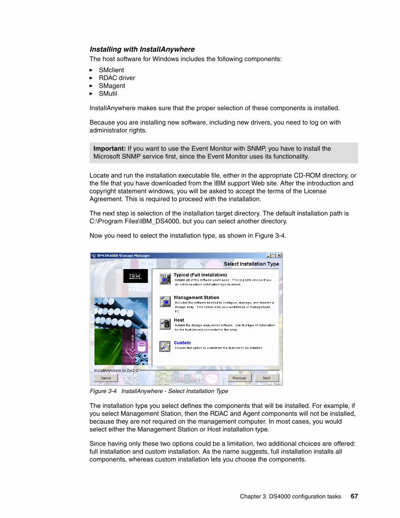
Installing with InstallAnywhere The host software for Windows includes the following components:
� SMclient � RDAC driver � SMagent � SMutil
InstallAnywhere makes sure that the proper selection of these components is installed.
Because you are installing new software, including new drivers, you need to log on with administrator rights.
Locate and run the installation executable file, either in the appropriate CD-ROM directory, or the file that you have downloaded from the IBM support Web site. After the introduction and copyright statement windows, you will be asked to accept the terms of the License Agreement. This is required to proceed with the installation.
The next step is selection of the installation target directory. The default installation path is C:\Program Files\IBM_DS4000, but you can select another directory.
Now you need to select the installation type, as shown in Figure 3-4.
Figure 3-4 InstallAnywhere - Select Installation Type
The installation type you select defines the components that will be installed. For example, if you select Management Station, then the RDAC and Agent components will not be installed, because they are not required on the management computer. In most cases, you would select either the Management Station or Host installation type.
Since having only these two options could be a limitation, two additional choices are offered: full installation and custom installation. As the name suggests, full installation installs all components, whereas custom installation lets you choose the components.
Important: If you want to use the Event Monitor with SNMP, you have to install the Microsoft SNMP service first, since the Event Monitor uses its functionality.
Chapter 3. DS4000 configuration tasks 67

The next installation screen asks you whether you wish to automatically start the Storage Manager Event Monitor. This depends on your particular management setup: In case there are several management machines, the Event Monitor should only run on one.
Finally, you are presented with the Pre-Installation Summary window, just to verify that you have selected correct installation options. Click the Install button and the actual installation process starts. When the installation process has completed, you need to restart the computer.
Starting the SMclientWhen you start the DS4000 Storage Manager Client, it launches the Enterprise Management window. With the new SM Client 9.1x release; you will be presented with the new configuring feature, Task Assistant, to aid you in the discovery and adding of storage servers that are detected. (If you do not want to use the Task Assistant, you can disable it by marking the appropriate check box. In case you want to use it again, you can invoke it from the Enterprise Management Window). The first time you start the client, you are prompted to select whether you want an initial discovery of available storage subsystems (see Figure 3-5).
Figure 3-5 Initial Automatic Discovery
The client software sends out broadcasts through Fibre Channel and the subnet of your IP network if it finds directly attached storage subsystems or other hosts running the DS4000 Storage Manager host agent with an attached storage subsystem.
You have to invoke the Automatic Discovery every time you add a new DS4000 Storage Server in your network or install new host agents on already attached systems. To have them detected in your Enterprise Management window, click Tools → Rescan. Then, all DS4000 Storage Servers are listed in the Enterprise Management window, as shown in Figure 3-6.
Figure 3-6 Example DS4000 Enterprise Management Window
68 DS4000 Best Practices and Performance Tuning Guide
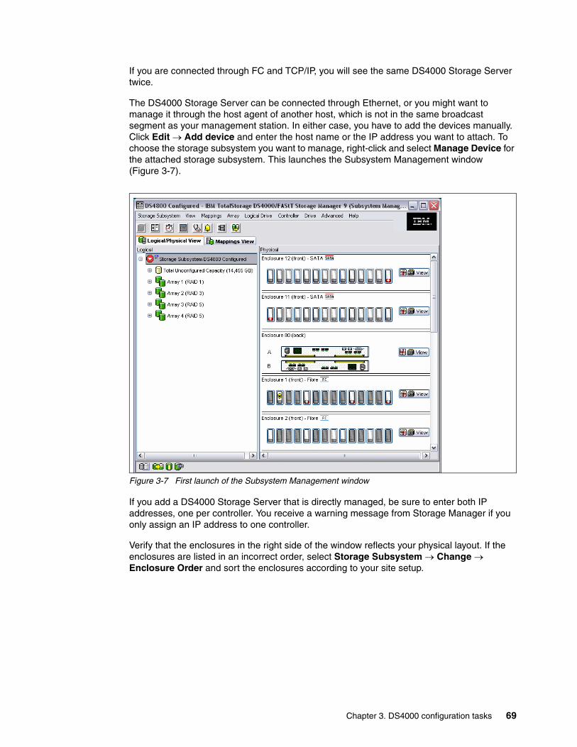
If you are connected through FC and TCP/IP, you will see the same DS4000 Storage Server twice.
The DS4000 Storage Server can be connected through Ethernet, or you might want to manage it through the host agent of another host, which is not in the same broadcast segment as your management station. In either case, you have to add the devices manually. Click Edit → Add device and enter the host name or the IP address you want to attach. To choose the storage subsystem you want to manage, right-click and select Manage Device for the attached storage subsystem. This launches the Subsystem Management window (Figure 3-7).
Figure 3-7 First launch of the Subsystem Management window
If you add a DS4000 Storage Server that is directly managed, be sure to enter both IP addresses, one per controller. You receive a warning message from Storage Manager if you only assign an IP address to one controller.
Verify that the enclosures in the right side of the window reflects your physical layout. If the enclosures are listed in an incorrect order, select Storage Subsystem → Change → Enclosure Order and sort the enclosures according to your site setup.
Chapter 3. DS4000 configuration tasks 69

3.2 DS4000 cablingIn the following sections, we explain the typical recommended cabling configuration for the DS4100, DS4300,DS4400,DS4500, and DS4800, respectively. A basic design point of a DS4000 Storage Server is to enable hosts to directly attach it.
However, the best practice for attaching host systems to your DS4000 storage is to use fabric attached (SAN attached), with Fibre switches. Both methods are explained in this section for each DS4000 Storage Server type.
3.2.1 DS4100 and DS4300 host cabling configurationHere we describe the various cabling configurations that you can use.
Direct attachBoth the DS4100, and the DS4300 offer fault tolerance by the use of two host HBAs connected to two RAID controllers in the DS4000 storage servers. At the same time, you can get higher performance, because the dual active controllers allow for distribution of the load across the two paths. See the left side of Figure 3-8 for an example of the DS4300.
Figure 3-8 DS4300 cabling configuration
These two DS4000 Storage servers can support a dual-node cluster configuration without using a switch, shown on the right side of Figure 3-8. This provides the lowest priced solution for a 2-node cluster environment due to four Fibre Channel host ports on the storage servers.
Fibre switch attached The recommended configuration is to connect the DS4100, and DS4300 to managed hubs, or Fibre switches to expand its connection for multiple servers, as shown in Figure 3-9.
Multiple hosts can access a single DS4000 system, but also have the capability of accessing data on any DS4000 subsystem within the SAN. This configuration allows more flexibility and growth capability within the SAN: The attachment of new systems is made easier when adopting such structured cabling techniques. This method of connection with Fibre switches is required for support of the Enhanced Remote Mirroring (ERM) feature if used. When using this method, you must ensure that you properly zone all storage and host HBAs to avoid fabric noise, or undesired data transfer interruptions from other members of the fabric. Best Practices for zoning recommends zoning a single initiator, and single target per zone.
70 DS4000 Best Practices and Performance Tuning Guide
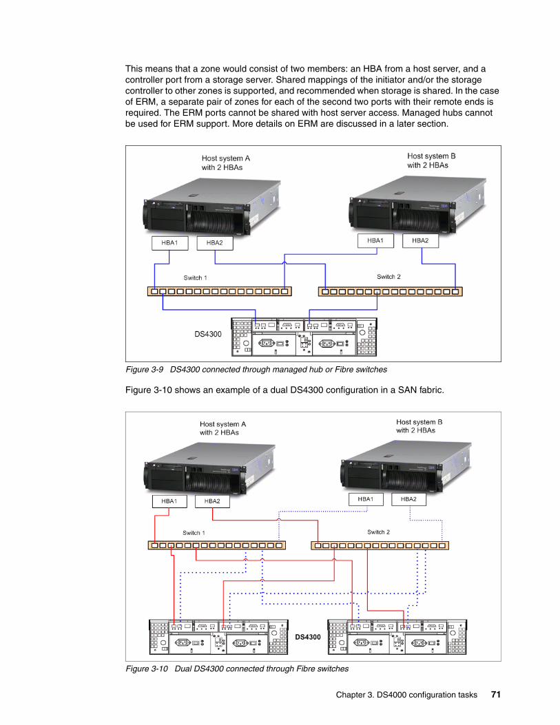
This means that a zone would consist of two members: an HBA from a host server, and a controller port from a storage server. Shared mappings of the initiator and/or the storage controller to other zones is supported, and recommended when storage is shared. In the case of ERM, a separate pair of zones for each of the second two ports with their remote ends is required. The ERM ports cannot be shared with host server access. Managed hubs cannot be used for ERM support. More details on ERM are discussed in a later section.
Figure 3-9 DS4300 connected through managed hub or Fibre switches
Figure 3-10 shows an example of a dual DS4300 configuration in a SAN fabric.
Figure 3-10 Dual DS4300 connected through Fibre switches
Chapter 3. DS4000 configuration tasks 71
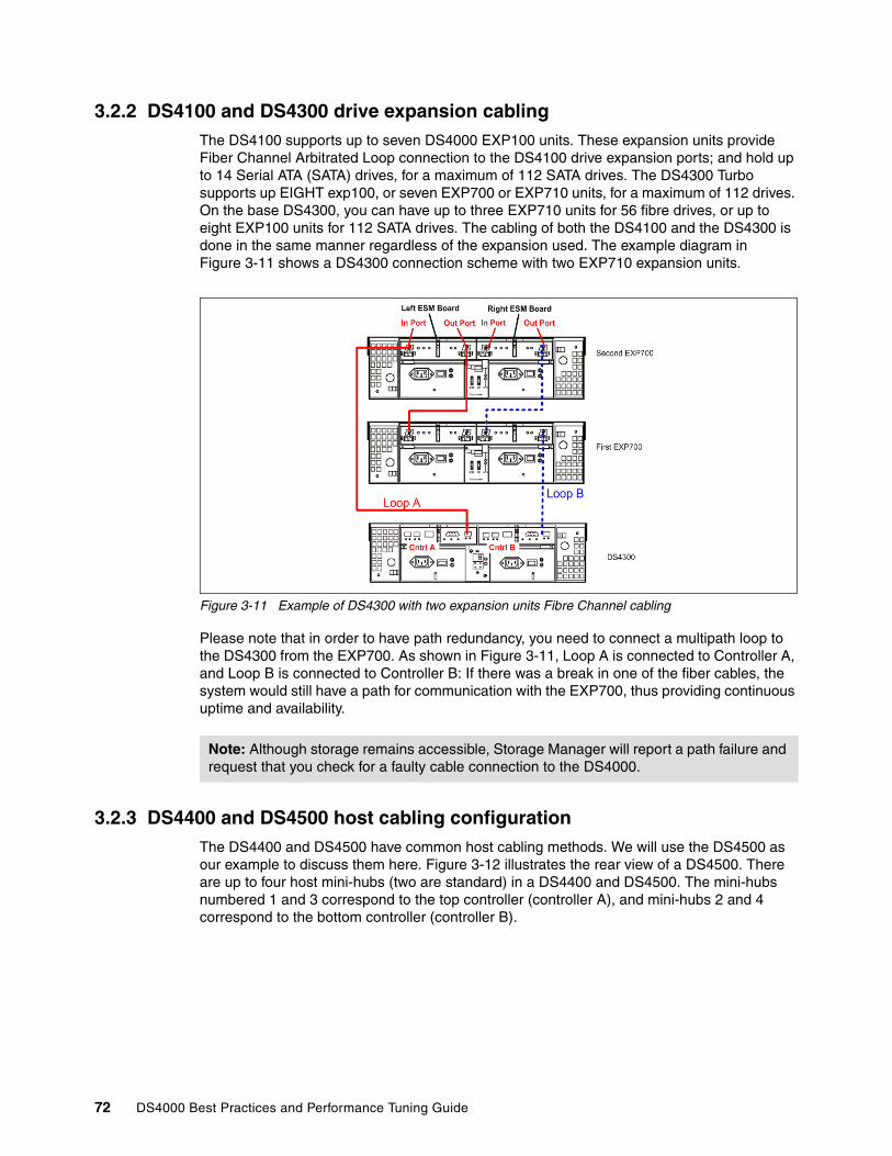
3.2.2 DS4100 and DS4300 drive expansion cablingThe DS4100 supports up to seven DS4000 EXP100 units. These expansion units provide Fiber Channel Arbitrated Loop connection to the DS4100 drive expansion ports; and hold up to 14 Serial ATA (SATA) drives, for a maximum of 112 SATA drives. The DS4300 Turbo supports up EIGHT exp100, or seven EXP700 or EXP710 units, for a maximum of 112 drives. On the base DS4300, you can have up to three EXP710 units for 56 fibre drives, or up to eight EXP100 units for 112 SATA drives. The cabling of both the DS4100 and the DS4300 is done in the same manner regardless of the expansion used. The example diagram in Figure 3-11 shows a DS4300 connection scheme with two EXP710 expansion units.
Figure 3-11 Example of DS4300 with two expansion units Fibre Channel cabling
Please note that in order to have path redundancy, you need to connect a multipath loop to the DS4300 from the EXP700. As shown in Figure 3-11, Loop A is connected to Controller A, and Loop B is connected to Controller B: If there was a break in one of the fiber cables, the system would still have a path for communication with the EXP700, thus providing continuous uptime and availability.
3.2.3 DS4400 and DS4500 host cabling configuration The DS4400 and DS4500 have common host cabling methods. We will use the DS4500 as our example to discuss them here. Figure 3-12 illustrates the rear view of a DS4500. There are up to four host mini-hubs (two are standard) in a DS4400 and DS4500. The mini-hubs numbered 1 and 3 correspond to the top controller (controller A), and mini-hubs 2 and 4 correspond to the bottom controller (controller B).
Note: Although storage remains accessible, Storage Manager will report a path failure and request that you check for a faulty cable connection to the DS4000.
72 DS4000 Best Practices and Performance Tuning Guide
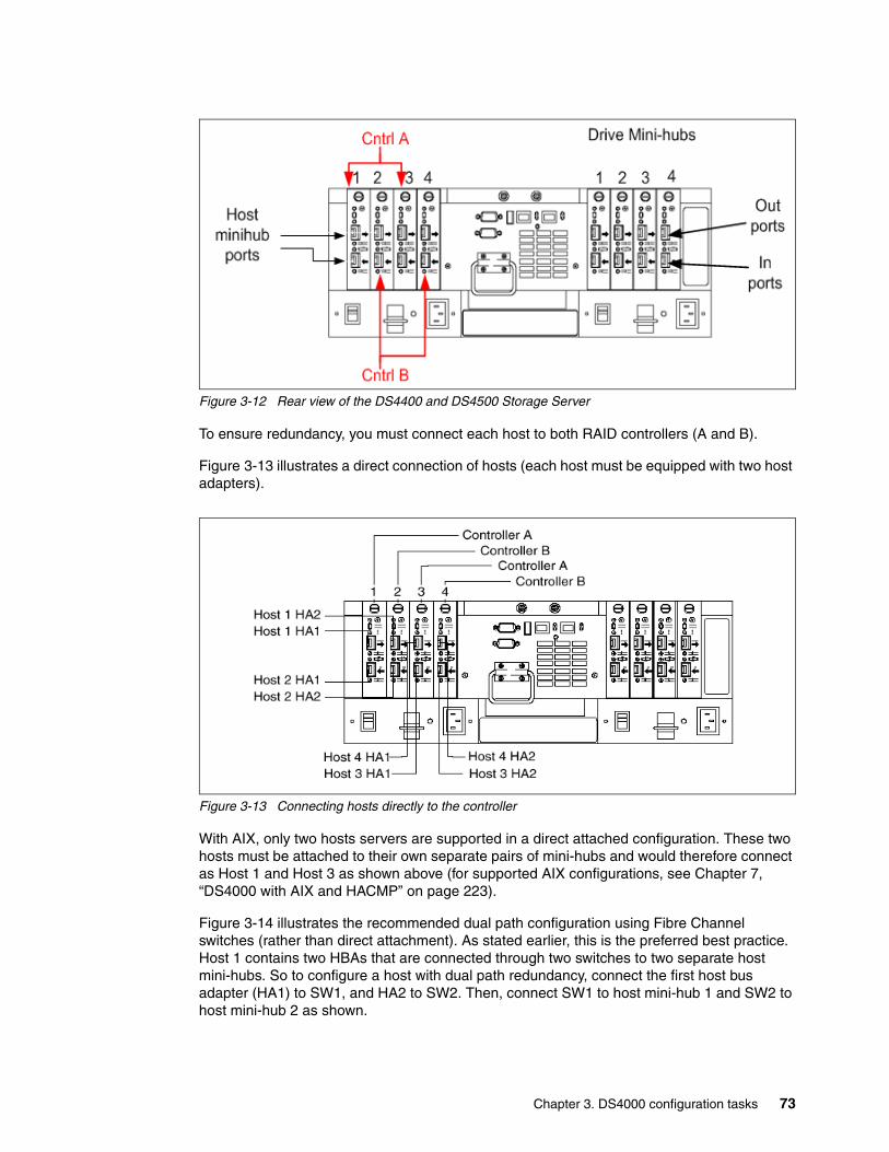
Figure 3-12 Rear view of the DS4400 and DS4500 Storage Server
To ensure redundancy, you must connect each host to both RAID controllers (A and B).
Figure 3-13 illustrates a direct connection of hosts (each host must be equipped with two host adapters).
Figure 3-13 Connecting hosts directly to the controller
With AIX, only two hosts servers are supported in a direct attached configuration. These two hosts must be attached to their own separate pairs of mini-hubs and would therefore connect as Host 1 and Host 3 as shown above (for supported AIX configurations, see Chapter 7, “DS4000 with AIX and HACMP” on page 223).
Figure 3-14 illustrates the recommended dual path configuration using Fibre Channel switches (rather than direct attachment). As stated earlier, this is the preferred best practice. Host 1 contains two HBAs that are connected through two switches to two separate host mini-hubs. So to configure a host with dual path redundancy, connect the first host bus adapter (HA1) to SW1, and HA2 to SW2. Then, connect SW1 to host mini-hub 1 and SW2 to host mini-hub 2 as shown.
Chapter 3. DS4000 configuration tasks 73
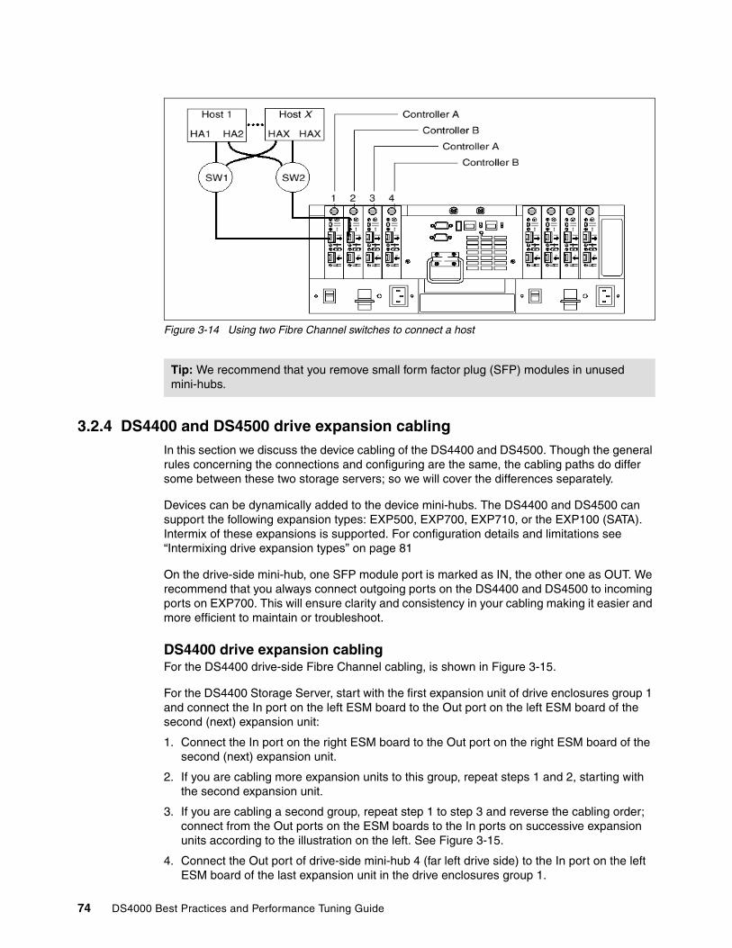
Figure 3-14 Using two Fibre Channel switches to connect a host
3.2.4 DS4400 and DS4500 drive expansion cablingIn this section we discuss the device cabling of the DS4400 and DS4500. Though the general rules concerning the connections and configuring are the same, the cabling paths do differ some between these two storage servers; so we will cover the differences separately.
Devices can be dynamically added to the device mini-hubs. The DS4400 and DS4500 can support the following expansion types: EXP500, EXP700, EXP710, or the EXP100 (SATA). Intermix of these expansions is supported. For configuration details and limitations see “Intermixing drive expansion types” on page 81
On the drive-side mini-hub, one SFP module port is marked as IN, the other one as OUT. We recommend that you always connect outgoing ports on the DS4400 and DS4500 to incoming ports on EXP700. This will ensure clarity and consistency in your cabling making it easier and more efficient to maintain or troubleshoot.
DS4400 drive expansion cablingFor the DS4400 drive-side Fibre Channel cabling, is shown in Figure 3-15.
For the DS4400 Storage Server, start with the first expansion unit of drive enclosures group 1 and connect the In port on the left ESM board to the Out port on the left ESM board of the second (next) expansion unit:
1. Connect the In port on the right ESM board to the Out port on the right ESM board of the second (next) expansion unit.
2. If you are cabling more expansion units to this group, repeat steps 1 and 2, starting with the second expansion unit.
3. If you are cabling a second group, repeat step 1 to step 3 and reverse the cabling order; connect from the Out ports on the ESM boards to the In ports on successive expansion units according to the illustration on the left. See Figure 3-15.
4. Connect the Out port of drive-side mini-hub 4 (far left drive side) to the In port on the left ESM board of the last expansion unit in the drive enclosures group 1.
Tip: We recommend that you remove small form factor plug (SFP) modules in unused mini-hubs.
74 DS4000 Best Practices and Performance Tuning Guide
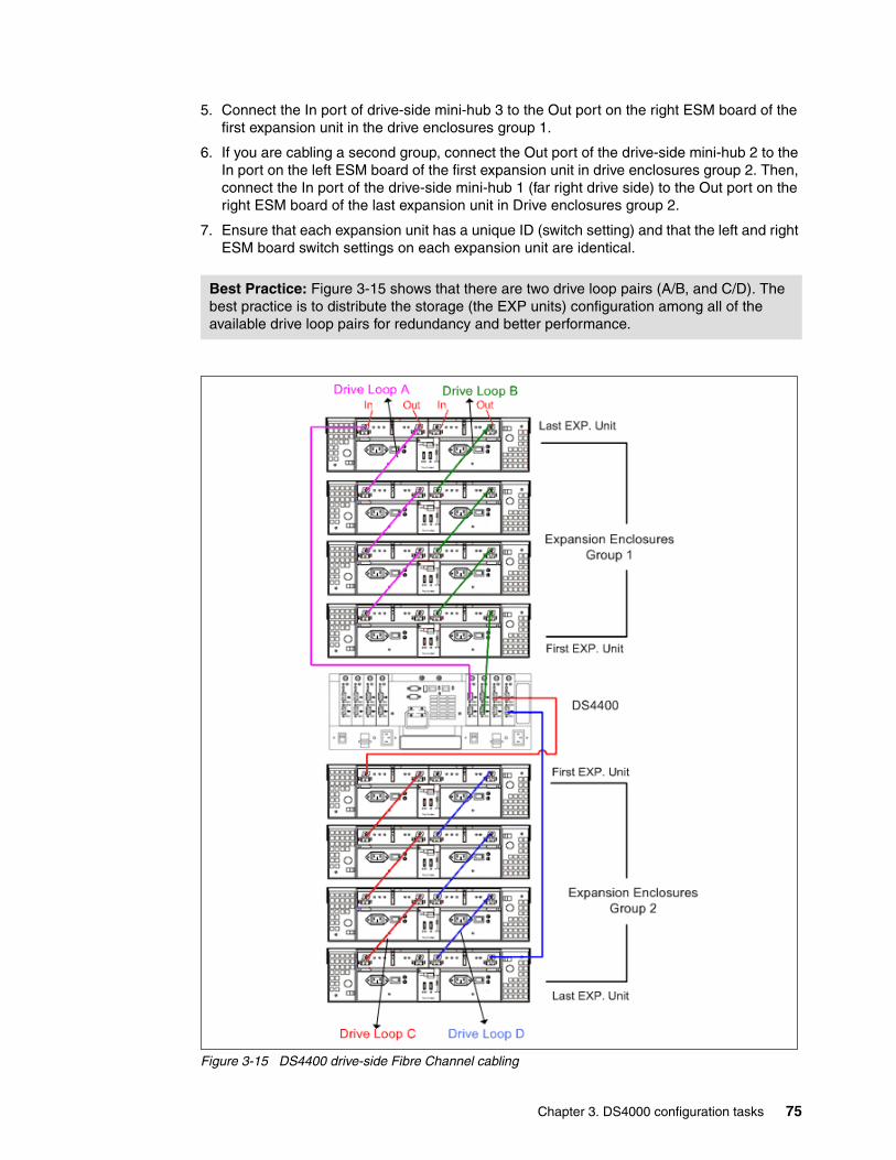
5. Connect the In port of drive-side mini-hub 3 to the Out port on the right ESM board of the first expansion unit in the drive enclosures group 1.
6. If you are cabling a second group, connect the Out port of the drive-side mini-hub 2 to the In port on the left ESM board of the first expansion unit in drive enclosures group 2. Then, connect the In port of the drive-side mini-hub 1 (far right drive side) to the Out port on the right ESM board of the last expansion unit in Drive enclosures group 2.
7. Ensure that each expansion unit has a unique ID (switch setting) and that the left and right ESM board switch settings on each expansion unit are identical.
Figure 3-15 DS4400 drive-side Fibre Channel cabling
Best Practice: Figure 3-15 shows that there are two drive loop pairs (A/B, and C/D). The best practice is to distribute the storage (the EXP units) configuration among all of the available drive loop pairs for redundancy and better performance.
Chapter 3. DS4000 configuration tasks 75

DS4500 drive expansion cablingThe DS4500 Storage Server is of a newer technology, and as such, it has more and faster Fibre Channel driver ASICs in its design. With this difference, you need to ensure that you spread the connections across all of the ASICs for best reliability and redundant paths. Figure 3-16 shows the cabling procedure for the DS4500.
Figure 3-16 DS4500 drive-side Fibre Channel cabling
1. Starting with the first expansion unit of drive enclosures group 1 and connect the In port on the left ESM board to the Out port on the left ESM board of the second (next) expansion unit.
DS4500
76 DS4000 Best Practices and Performance Tuning Guide

2. Connect the In port on the right ESM board to the Out port on the right ESM board of the second (next) expansion unit.
3. If you are cabling more expansion units to this group, repeat steps 1 and 2, starting with the second expansion unit.
4. If you are cabling a second group, repeat step 1 to step 3 and reverse the cabling order; connect from the Out ports on the ESM boards to the In ports on successive expansion units according to the illustration on the left. See Figure 3-15.
5. Connect the Out port of drive-side mini-hub 4 (far left drive side) to the In port on the left ESM board of the last expansion unit in the drive enclosures group 1.
6. Connect the In port of drive-side mini-hub 2 to the Out port on the right ESM board of the first expansion unit in the drive enclosures group 1.
7. If you are cabling a second group, connect the Out port of the drive-side mini-hub 3 to the In port on the left ESM board of the first expansion unit in drive enclosures group 2. Then, connect the In port of the drive-side mini-hub 1 (far right drive side) to the Out port on the right ESM board of the last expansion unit in Drive enclosures group 2.
8. Ensure that each expansion unit has a unique ID (switch setting) and that the left and right ESM board switch settings on each expansion unit are identical.
3.2.5 DS4800 host cabling configurationThe new DS4800 Storage Server supports a maximum of four independent switched or Arbitrated Loop port connections to host per storage controller. This enables it to support up to four dual pathed As with previous DS4000 systems, the DS4800 does support direct attached hosts in an Arbitrated Loop; however, the recommendation is to connect using a SAN fabric (switch) environment. The direct attached configuration is shown in Figure 3-17.
Figure 3-17 Basic DS4800 host side direct connect cabling
Chapter 3. DS4000 configuration tasks 77
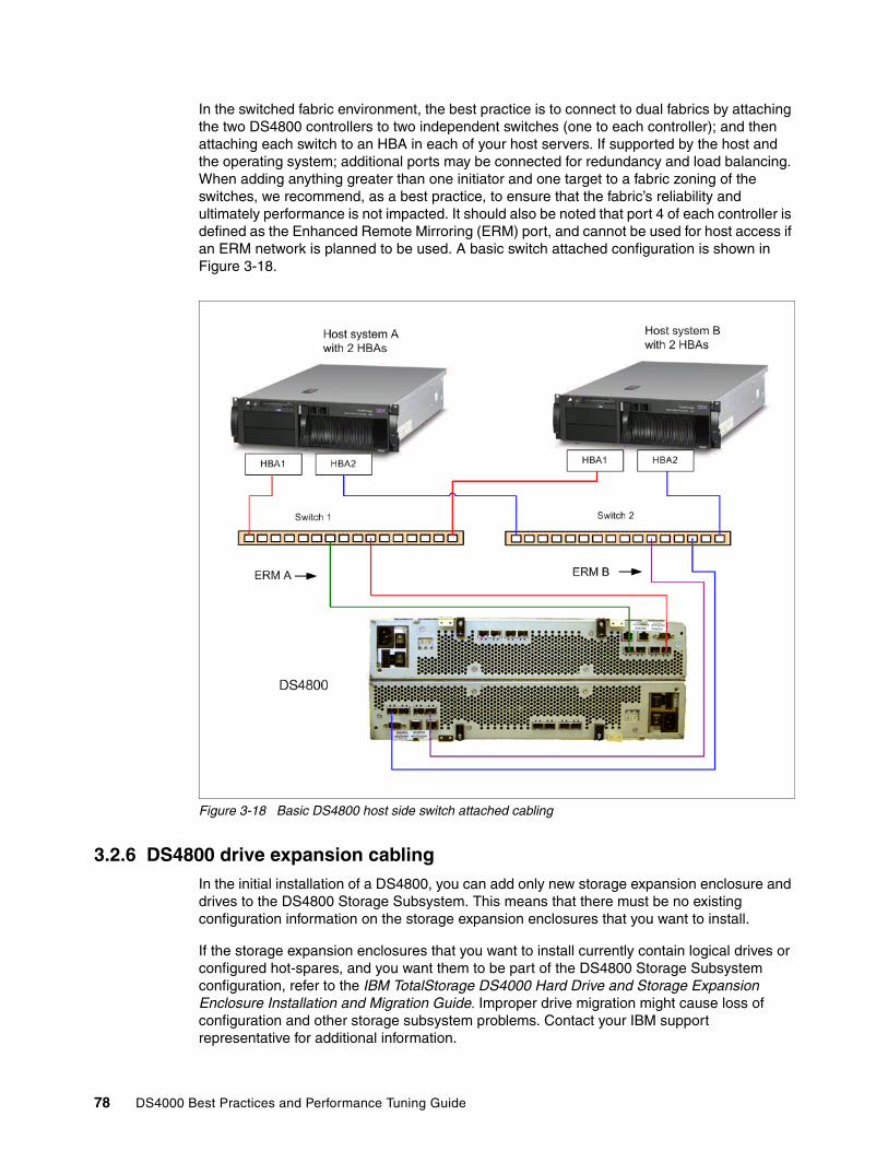
In the switched fabric environment, the best practice is to connect to dual fabrics by attaching the two DS4800 controllers to two independent switches (one to each controller); and then attaching each switch to an HBA in each of your host servers. If supported by the host and the operating system; additional ports may be connected for redundancy and load balancing. When adding anything greater than one initiator and one target to a fabric zoning of the switches, we recommend, as a best practice, to ensure that the fabric’s reliability and ultimately performance is not impacted. It should also be noted that port 4 of each controller is defined as the Enhanced Remote Mirroring (ERM) port, and cannot be used for host access if an ERM network is planned to be used. A basic switch attached configuration is shown in Figure 3-18.
Figure 3-18 Basic DS4800 host side switch attached cabling
3.2.6 DS4800 drive expansion cablingIn the initial installation of a DS4800, you can add only new storage expansion enclosure and drives to the DS4800 Storage Subsystem. This means that there must be no existing configuration information on the storage expansion enclosures that you want to install.
If the storage expansion enclosures that you want to install currently contain logical drives or configured hot-spares, and you want them to be part of the DS4800 Storage Subsystem configuration, refer to the IBM TotalStorage DS4000 Hard Drive and Storage Expansion Enclosure Installation and Migration Guide. Improper drive migration might cause loss of configuration and other storage subsystem problems. Contact your IBM support representative for additional information.
78 DS4000 Best Practices and Performance Tuning Guide

With the DS4800 Storage Server, the recommended drive expansion cabling method is to connect drive channel 1 of controller A (ports 4 and 3) and drive channel 3 of controller B (ports 1 and 2) to form a DS4800 Storage Subsystem redundant drive loop/channel pair (loop pairs 1 and 2 in Figure 3-21). If any component of drive channel 1 fails, the RAID controllers can still access the storage expansion enclosures in redundant drive loop 1 through drive channel 3. Similarly, drive channel 2 of controller A (ports 2 and 1) and drive channel 4 of controller B (port 4 and 3) combine to form the second set of redundant drive loop/channel pairs (loop pairs 3 and 4 in Figure 3-21). If any component of drive channel 2 fails, the RAID controllers can still access the storage expansion enclosures in redundant drive loop pairs 3 and 4, through drive channel 4.
Figure 3-19 shows the storage expansion enclosures in each drive loop pairs connected to only one drive port in the two-ported drive channel. For example, in drive channel/loop pair 1, only port 4 of channel 1 and port 1 of channel 3 are used. This results in only half of the storage expansion enclosures in the redundant drive loop pair being connected to the first port of the dual-ported drive channel. The other half of the enclosures are connected to the second port of the dual-ported drive channels.
Figure 3-19 through Figure 3-21 are examples of different quantities of drive expansion being installed with the DS4800 Server.
Figure 3-19 DS4800 with two drive expansion enclosures
Chapter 3. DS4000 configuration tasks 79

Figure 3-20 DS4800 with eight drive expansion trays
Figure 3-21 DS4800 with maximum (16) drive expansion trays
3.2.7 Expansion enclosuresThe DS4000 Storage Server offers disk expansions of both Fibre Channel drives, and/or SATA drive types. Support of expansions may be limited on certain models of the DS4000 Storage Server. Table 3-1 shows the DS4000 Storage Servers and their supported expansions.
80 DS4000 Best Practices and Performance Tuning Guide
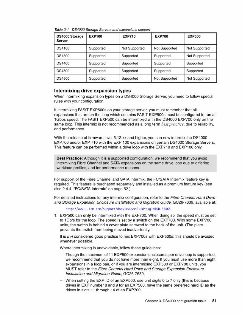
Table 3-1 DS4000 Storage Servers and expansions support
Intermixing drive expansion typesWhen intermixing expansion types on a DS4000 Storage Server, you need to follow special rules with your configuration.
If intermixing FAStT EXP500s on your storage server, you must remember that all expansions that are on the loop which contains FAStT EXP500s must be configured to run at 1Gbps speed. The FAStT EXP500 can be intermixed with the DS4000 EXP700 only on the same loop. This intermix is not recommended as a long term best practice, due to reliability, and performance.
With the release of firmware level 6.12.xx and higher, you can now intermix the DS4000 EXP700 and/or EXP 710 with the EXP 100 expansions on certain DS4000 Storage Servers. This feature can be performed within a drive loop with the EXP710 and EXP100 only.
For support of the Fibre Channel and SATA intermix, the FC/SATA Intermix feature key is required. This feature is purchased separately and installed as a premium feature key (see also 2.4.4, “FC/SATA Intermix” on page 52 ).
For detailed instructions for any intermix configuration, refer to the Fibre Channel Hard Drive and Storage Expansion Enclosure Installation and Migration Guide, GC26-7639, available at:
http://www-1.ibm.com/support/docview.wss?uid=psg1MIGR-55466
1. EXP500 can only be intermixed with the EXP700. When doing so, the speed must be set to 1Gb/s for the loop. The speed is set by a switch on the EXP700. With some EXP700 units, the switch is behind a cover plate screwed to the back of the unit. (The plate prevents the switch from being moved inadvertently.
It is not considered good practice to mix EXP700s with EXP500s; this should be avoided whenever possible.
Where intermixing is unavoidable, follow these guidelines:
– Though the maximum of 11 EXP500 expansion enclosures per drive loop is supported, we recommend that you do not have more than eight. If you must use more than eight expansions in a loop pair, or if you are intermixing EXP500 or EXP700 units, you MUST refer to the Fibre Channel Hard Drive and Storage Expansion Enclosure Installation and Migration Guide, GC26-7639.
– When setting the EXP ID of an EXP500, use unit digits 0 to 7 only (this is because drives in EXP number 8 and 9 for an EXP500, have the same preferred hard ID as the drives in slots 11 through 14 of an EXP700.
DS4000 Storage Server
EXP100 EXP710 EXP700 EXP500
DS4100 Supported Not Supported Not Supported Not Supported
DS4300 Supported Supported Supported Not Supported
DS4400 Supported Supported Supported Supported
DS4500 Supported Supported Supported Supported
DS4800 Supported Supported Not Supported Not Supported
Best Practice: Although it is a supported configuration, we recommend that you avoid intermixing Fibre Channel and SATA expansions on the same drive loop due to differing workload profiles, and for performance reasons.
Chapter 3. DS4000 configuration tasks 81

– Limit the number of drives installed in the DS4000 to 80% of maximum capacity. In an intermix environment, with a maximum number allowed of 224, 180 drives would be the maximum number recommended.
2. EXP700, EXP 710, and EXP100 can all be intermixed; however, our recommendation is as follows:
– When intermixing EXP700 and EXP710 on the same loop(s), group the EXP710s together.
– Although it is a supported configuration, as a best practice, we recommend that you avoid intermixing the EXP100 and either the EXP700, or EXP710 on the same loop(s) when at all possible.
A Fibre Channel loop supports up to 127 addresses. This means the DS4400 and DS4500 can support up to 8 EXP700 expansion enclosures per drive loop, for a total of 112 or 110 drives being addressed. With EXP100, and EXP710 this limitation does not have the same impact; however, the supported configurations are still limited to the same number of expansions per loop by design.
Because up to four fully redundant loops can be set, we can connect up to 16 EXP100, EXP700, EXP710 expansion enclosures, for a total of up to 224 disk drives without a single point of failure. See cabling section for the appropriate DS4000 Storage Server you are working with.
Expansion enclosure ID addressingIt is very important to correctly set the expansion enclosure ID switches on the EXPs. The IDs are used to differentiate multiple EXP enclosures that are connected to the same DS4000 Storage Server. Each EXP must use a unique value. The DS4000 Storage Manager uses the expansion enclosure IDs to identify each DS4000 EXP enclosure.
Additionally, the Fibre Channel loop ID for each disk drive is automatically set according to the following items:
� The EXP bay where the disk drive is inserted� EXP ID setting
It is important to avoid hard ID contention (two disks having the same ID on the loop). Such contention can occur when the units digit of two drive expansions on the same drive side loop are identical. For example, expansions with IDs 0 and 10, 4 and 14, and 23 and 73, could all have hard ID contention between devices.
Best Practice: The EXP500 is a historical expansion with slower speed and lower performance. Its older technology limits its ability to keep pace with the faster and more reliable newer designs. Migrating the data to a newer EXP710 with 2Gbps drives is recommended to better serve your long term goals.
Important: We recommend that you use either an EXP100 or an EXP710 with the DS4300, DS4400, DS4500, and DS4800 storage servers.
82 DS4000 Best Practices and Performance Tuning Guide

3.3 Configuring the DS4000 Storage ServerNow that you have set up the Storage Server and it is connected to a server or the SAN, you can proceed with additional configuration and storage setting tasks. If there is previous configuration data on the DS4000 storage server that you wish to be able to reference, then first save a copy of the storage subsystem profile to a file. Once you have completed your changes, you should save the profile to a (different) file as well. This will be of great value when you are discussing questions or problems with support; or reviewing your configuration with your performance data.
The configuration changes you desire can be done using the new storage subsystem level Task Assistant capabilities with the SM Client 9.1x code, or by following the steps outlined here.
Before defining arrays or logical drives, you must perform some basic configuration steps. This also applies when you reset the configuration of your DS4000 Storage Server:
1. If you install more than one DS4000 Storage Server, it is important to give them literal names. To name or rename the DS4000 Storage Server, open the Subsystem Management window. Right-click the subsystem, and click Storage Subsystem → Rename.
2. Because the DS4000 Storage Server stores its own event log, synchronize the controller clocks with the time of the host system used to manage the DS4000 units. If you have not already set the clocks on the Storage Servers, set them now. Be sure that your local system is working using the correct time. Then, click Storage Subsystem → Set Controller Clock.
3. For security reasons, especially if the DS4000 Storage Server is directly attached to the network, you should set a password. This password is required for all actions on the DS4000 Storage Server that change or update the configuration in any way.
To set a password, highlight the storage subsystem, right-click, and click Change → Password. This password is then stored on the DS4000 Storage Server. It is used if you connect through another DS4000 client. It does not matter whether you are using in-band or out-of-band management.
Best Practice: Any changes made to a storage server configuration should be preceded, and concluded, with the saving of the storage subsystem profile to a file, for future reference.
Note: Make sure the time of the controllers and the attached systems are synchronized. This simplifies error determination when you start comparing the different event logs. A network time server can be useful for this purpose.
Chapter 3. DS4000 configuration tasks 83
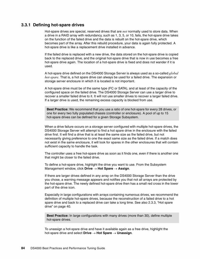
3.3.1 Defining hot-spare drivesHot-spare drives are special, reserved drives that are not normally used to store data. When a drive in a RAID array with redundancy, such as 1, 3, 5, or 10, fails, the hot-spare drive takes on the function of the failed drive and the data is rebuilt on the hot-spare drive, which becomes part of the array. After this rebuild procedure, your data is again fully protected. A hot-spare drive is like a replacement drive installed in advance.
If the failed drive is replaced with a new drive, the data stored on the hot-spare drive is copied back to the replaced drive, and the original hot-spare drive that is now in use becomes a free hot-spare drive again. The location of a hot-spare drive is fixed and does not wander if it is used.
A hot-spare drive defined on the DS4000 Storage Server is always used as a so-called global hot-spare. That is, a hot spare drive can always be used for a failed drive. The expansion or storage server enclosure in which it is located is not important.
A hot-spare drive must be of the same type (FC or SATA), and at least of the capacity of the configured space on the failed drive. The DS4000 Storage Server can use a larger drive to recover a smaller failed drive to it. It will not use smaller drives to recover a larger failed drive. If a larger drive is used, the remaining excess capacity is blocked from use.
When a drive failure occurs on a storage server configured with multiple hot-spare drives, the DS4000 Storage Server will attempt to find a hot spare drive in the enclosure with the failed drive first. It will find a drive that is at least the same size as the failed drive, but not necessarily giving preference to one the exact same size as the failed drive. If a match does not exist in the same enclosure, it will look for spares in the other enclosures that will contain sufficient capacity to handle the task.
The controller uses a free hot-spare drive as soon as it finds one, even if there is another one that might be closer to the failed drive.
To define a hot-spare drive, highlight the drive you want to use. From the Subsystem Management window, click Drive → Hot Spare → Assign.
If there are larger drives defined in any array on the DS4000 Storage Server than the drive you chose, a warning message appears and notifies you that not all arrays are protected by the hot-spare drive. The newly defined hot-spare drive then has a small red cross in the lower part of the drive icon.
Especially in large configurations with arrays containing numerous drives, we recommend the definition of multiple hot-spare drives, because the reconstruction of a failed drive to a hot spare drive and back to a replaced drive can take a long time. See also 2.3.3, “Hot spare drive” on page 40.
To unassign a hot-spare drive and have it available again as a free drive, highlight the hot-spare drive and select Drive → Hot Spare → Unassign.
Best Practice: We recommend that you use a ratio of one hot-spare for every 28 drives, or one for every two fully populated chassis (controller or enclosure). A pool of up to 15 hot-spare drives can be defined for a given Storage Subsystem.
Best Practice: In large configurations with many drives (more than 30), define multiple hot-spare drives.
84 DS4000 Best Practices and Performance Tuning Guide

3.3.2 Creating arrays and logical drivesAt this stage, the storage subsystem has been installed and upgraded to the newest microcode level. You can now configure the arrays and logical drives according to your requirements. With the SM Client you can use an automatic default configuration mode to configure the arrays and LUNs for the sizes you want and the RAID type you select. If you have planned your configuration for maximum performance and reliability as discussed and recommended in 2.3.1, “Arrays and RAID levels” on page 29 and also in 4.5.6, “Arrays and logical drives” on page 136, you will need to define them manually to enter your specific configuration and needs.
If you need any further assistance with how to define the available drives into the arrays you want, or logical drive definitions, or which restrictions apply to avoid improper or inefficient configurations of the DS4000 Storage Server, see the IBM Redbook, IBM TotalStorage DS4000 Series and Storage Manager, SG24-7010, available at:
http://www.redbooks.ibm.com/redbooks/pdfs/sg247010.pdf
To create arrays and logical drives, you can define logical drives from unconfigured-capacity or free-capacity nodes on the Storage Subsystem.
The main difference is that you have to decide whether to use unconfigured capacity on free disks or free capacity in an already existing array:
� When you create a logical drive from unconfigured capacity, you create an array and the logical drive at the same time. Note that the unconfigured capacity for Fibre Channel and SATA disks are grouped separately.
� When you create a logical drive from free capacity, you create an additional logical drive on an already existing array from free unconfigured space that is available.
While creating your logical drives, select the “Customize settings” to be able to set specific values for the cache settings, and segment size for the logical drive options.
1. In the Subsystem Management window, right-click the unconfigured capacity and select Create Logical Drive.
This action starts the wizard for creating the logical drives. The first window of the wizard is an introduction to the process as shown in Figure 3-22. Read the introduction and then click Next in order to proceed.
Best Practice: When defining the arrays and logical drives for your configuration, we recommend that you plan your layout and use the manual configuration method to select the desired drives and specify your settings.
Chapter 3. DS4000 configuration tasks 85
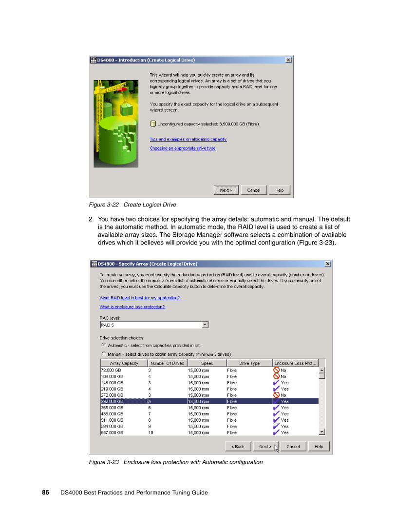
Figure 3-22 Create Logical Drive
2. You have two choices for specifying the array details: automatic and manual. The default is the automatic method. In automatic mode, the RAID level is used to create a list of available array sizes. The Storage Manager software selects a combination of available drives which it believes will provide you with the optimal configuration (Figure 3-23).
Figure 3-23 Enclosure loss protection with Automatic configuration
86 DS4000 Best Practices and Performance Tuning Guide
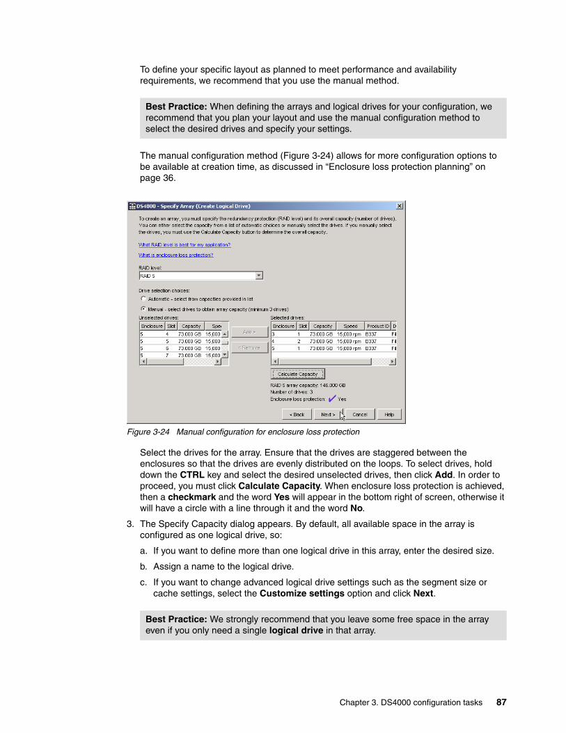
To define your specific layout as planned to meet performance and availability requirements, we recommend that you use the manual method.
The manual configuration method (Figure 3-24) allows for more configuration options to be available at creation time, as discussed in “Enclosure loss protection planning” on page 36.
Figure 3-24 Manual configuration for enclosure loss protection
Select the drives for the array. Ensure that the drives are staggered between the enclosures so that the drives are evenly distributed on the loops. To select drives, hold down the CTRL key and select the desired unselected drives, then click Add. In order to proceed, you must click Calculate Capacity. When enclosure loss protection is achieved, then a checkmark and the word Yes will appear in the bottom right of screen, otherwise it will have a circle with a line through it and the word No.
3. The Specify Capacity dialog appears. By default, all available space in the array is configured as one logical drive, so:
a. If you want to define more than one logical drive in this array, enter the desired size.
b. Assign a name to the logical drive.
c. If you want to change advanced logical drive settings such as the segment size or cache settings, select the Customize settings option and click Next.
Best Practice: When defining the arrays and logical drives for your configuration, we recommend that you plan your layout and use the manual configuration method to select the desired drives and specify your settings.
Best Practice: We strongly recommend that you leave some free space in the array even if you only need a single logical drive in that array.
Chapter 3. DS4000 configuration tasks 87

4. The Customize Advanced Logical Drive Parameters dialog appears. You can customize the logical drive using predefined defaults, or manually change the cache read ahead multiplier, segment size, and controller ownership.
a. For logical drive I/O characteristics, you can specify file system, database, or multimedia defaults. The Custom option allows you to manually select the cache read ahead multiplier and segment size.
b. The segment size is chosen according to the usage pattern. For custom settings, you can directly define the segment size. Storage Manager 9.10 introduced the possibility to set the segment size of 512 KB through the GUI (older versions only allowed this through the CLI).
c. As discussed earlier the cache read ahead setting is really an on or off decision since the read ahead multiplier is dynamically adjusted in the firmware. It should be set to any non-zero value to enable the dynamic cache read-ahead function.
d. The preferred controller handles the logical drive normally if both controllers and I/O paths are online. You can distribute your logical drives between both controllers to provide better load balancing between them. The default is to alternate the logical drives on the two controllers.
e. Obviously it is better to spread the logical drives by the load they cause on the controller. It is possible to monitor the load of each logical drive on the controllers with the performance monitor and change the preferred controller in case of need.
When you have completed setting your values as desired (either default or custom), click Next to complete the creation of the logical drive.
5. The Specify Logical Drive-to-LUN Mapping dialog appears. This step allows you to choose between default mapping and storage partitioning. Storage partitioning is a separate licensing option. In the case of storage partitioning being used, you must select Map later using the Mappings View.
If you choose Default mapping, then the physical volume will be mapped to the default host group. If there are host groups or hosts defined under the default host group, they will all be able to access the logical drive.
If the logical drive is smaller than the total capacity of the array, a window opens and asks whether you want to define another logical drive on the array. The alternative is to leave the space as unconfigured capacity. After you define all logical drives on the array, the array is now initialized and immediately accessible.
If you left unconfigured capacity inside the array, you can define another logical drive later in this array. Simply highlight this capacity, right-click, and choose Create Logical Drive. Simply follow the steps that we outlined in this section, except for the selection of drives and RAID level. Because you already defined arrays that contain free capacity, you can choose where to store the new logical drive, on an existing array or on a new one.
As stated earlier, it is always good to leave a small portion of space unused on an array for emergency use. This is also a good practice for future enhancements and code releases, as there can be slight changes in the available size. If moving from a 5.x based storage server firmware to a 6.1x based, you will encounter this issue and need to expand the array to be able to handle a full sized LUN on the 6.1x server. This can impact VolumeCopy, and Enhanced Remote Mirroring efforts especially. If planning to use the FlashCopy feature, this may be a good place to plan to have repositories placed.
88 DS4000 Best Practices and Performance Tuning Guide

3.3.3 Configuring storage partitioningAs the DS4000 Storage Server is capable of having heterogeneous hosts attached, a way is needed to define which hosts are able to access which logical drives on the DS4000 Storage Server. Therefore, you need to configure storage partitioning, for two reasons:
� Each host operating system has slightly different settings required for proper operation on the DS4000 Storage Server. For that reason, you need to tell the storage subsystem the host type that is attached.
� There is interference between the hosts if every host has access to every logical drive. By using storage partitioning, you mask logical drives from hosts which are not to use them (also known as LUN masking), and you ensure that each host or host group only has access to its assigned logical drives. You can have a maximum of 256 logical drives assigned to a single storage partition. You may have a maximum of 2048 logical drives (LUNs) per storage server depending on the model.
The process of defining the storage partitions is as follows:
1. Define host groups. 2. Define hosts. 3. Define host ports for each host. 4. Define storage partitions by assigning logical drives to the hosts or host groups.
Storage Manager Version 9.12 introduced the Task Assistant wizards. You can now use two new wizards that assist you with setting up the storage partitioning:
� Define Host wizard� Storage Partitioning wizard
The first step is to select the Mappings View in the Subsystem Management Window. All functions that are performed with regards to partitioning are performed from within this view.
If you have not defined any storage partitions yet, the Mapping Start-Up Help window pops up. The information in the window advises you to only create the host groups you intend to use. For example, if you want to attach a cluster of host servers, then you surely need to create a host group for them. On the other hand, if you want to attach a host that is not a part of the cluster, it is not necessary put it into a particular host group. However, as requirements may change, we recommend that you create a host group anyway.
For detailed information for each of the process steps, see the IBM Redbook, IBM TotalStorage DS4000 Series and Storage Manager, SG24-7010.
Here are some additional points to be aware of when performing your partition mapping:
1. All information, such as host ports and logical drive mappings, is shown and configured in the Mapping View. The right side of the window lists all mappings that are owned by the object you choose in the left side.
Restriction: The maximum logical drives per partition can exceed some host limits. Check to be sure the host can support the number of logical drives that you are configuring for the partition. In some cases you may need to split the logical drives across two separate partitions, with a second set of host side HBAs.
Best Practice: We recommend that all hosts be mapped to a host group for their specific purpose. This is not required, but can prevent confusion and mistakes.
Chapter 3. DS4000 configuration tasks 89

2. If you highlight the storage subsystem, you see a list of all defined mappings. If you highlight a specific host group or host, only its mappings are listed.
3. If you accidentally assigned a host to the wrong host group, you can move the host to another group. Simply right-click the host name and select Move. A pop-up window opens and asks you to specify the host group name.
4. Storage partitioning of the DS4000 Storage Server is based on the World Wide Names of the host ports. The definitions for the host groups and the hosts only represent a view of the physical and logical setup of your fabric. Having this structure available makes it much easier to identify which host ports are allowed to see the same logical drives, and which are in different storage partitions.
5. Storage partitioning is not the only function of the storage server that uses the definition of the host port. When you define the host port, the host type of the attached host is defined as well. Through this information, the DS4000 determines what NVSRAM settings AVT, and RDAC it should expect to use with the host.
It is important to carefully choose the correct host type from the list of available types, because this is the part of the configuration dealing with heterogeneous host support. Each operating system expects slightly different settings and can handle SCSI commands a little differently. Incorrect selections can result in failure to boot, or loss of path failover function when attached to the storage server.
6. As the host port is identified by the World Wide Name of the host bus adapter, you may need to change it when an HBA failure results in replacement. This can be done by first highlighting the old host port, right-clicking, and selecting Replace... In the drop-down box, you see only the World Wide Names that are currently active. If you want to enter a host port that is not currently active, type the World Wide Name in the field. Be sure to check for typing errors. If the WWN does not appear in the drop-down box, you need to verify your zoning for accuracy or missing changes.
7. If you have a single server in a host group that has one or more logical drive assigned to it, we recommend that you assign the mapping to the host, and not the host group. Numerous servers can share a common host group; but may not necessarily share drives. Only place drives in the host group mapping that you truly want all hosts in the group to be able to share.
8. If you have a cluster, you will want to assign the logical drives that are to be shared across all, to the host group, so that all of the host nodes in the host group have access to them.
9. If you attached a host server that is not configured to use the inband management capabilities; we recommend that you ensure that the access LUN(s) are deleted or unconfigured from that host server’s mapping list.
Highlight the host or host group containing the system in the Mappings View. In the right side of the window, you see the list of all logical drives mapped to this host or host group. To delete the mapping of the access logical drive, right-click it and select Remove. The mapping of that access logical drive is deleted immediately. If you need to use the access LUN with another server, you will have the opportunity to do so when you create the host mapping. An access LUN is created whenever a host server partition is created.
Now all logical drives and their mappings are defined and are now accessible by their mapped host systems.
Note: If you create a new mapping or change an existing mapping of a logical drive, the change happens immediately. Therefore, make sure that this logical drive is not in use or even assigned by any of the machines attached to the storage subsystem.
90 DS4000 Best Practices and Performance Tuning Guide
To make the logical drives available to the host systems without rebooting, the DS4000 Utilities package provides a hot_add command line tool for some operating systems. You simply run hot_add, and all host bus adapters are re-scanned for new devices, and the devices should be accessible to the operating system.
You will need to take appropriate steps to enable the use of the storage inside the operating system, or by the volume manager software.
3.3.4 Configuring for Copy Services functionsThe DS4000 Storage Server has a complete set of Copy Services functions that can be added to it. These features are all enabled by premium feature keys which come in the following types:
� FlashCopy:
FlashCopy is used to create a point-in-time image copy of the base LUN for use by other system applications while the base LUN remains available to the base host application. The secondary applications can be read-only, such as a backup application, or they might also be read/write, for example, such as a test system or analysis application. For more in-depth application uses, we recommend that you use your FlashCopy image to create a VolumeCopy, which will be a complete image drive and fully independent of the base LUN image.
� VolumeCopy:
VolumeCopy creates a complete physical replication of one logical drive (source) to another (target) within the same Storage Subsystem. The target logical drive is an exact copy or clone of the source logical drive. This feature is designed as a system management tool for tasks such as relocating data to other drives for hardware upgrades or performance management, data backup, and restoring snapshot logical drive data. Because VolumeCopy is a full replication of a point-in-time image, it allows for analysis, mining, and testing without any degradation of the production logical drive performance. It also brings improvements to backup and restore operations, making them faster and eliminating I/O contention on the primary (source) logical drive. The use of the FlashCopy → Volume copy combined process is recommended as a best practice when used with RVM for Business Continuance and Disaster Recovery (BCDR) sites with short recovery time objectives (RTOs).
� Enhanced Remote Mirroring (ERM):
ERM is used to allow mirroring to another DS4000 Storage Server either co-located, or situated at another site. The main usage of this premium feature is for to enable business continuity in the event of a disaster or unrecoverable error at the primary storage server. It achieves this by maintaining two copies of a data set in two different locations, on two or more different Storage Servers and enabling a second Storage Subsystem to take over responsibility. Methods available for use with this feature are: synchronous, asynchronous, and asynchronous with write order consistency (WOC).
The configuration of all of these features are documented in great detail in the IBM Redbook, IBM TotalStorage DS4000 Series and Storage Manager, SG24-7010.available at:
http://www.redbooks.ibm.com/redbooks/pdfs/sg247010.pdf
Chapter 3. DS4000 configuration tasks 91
3.4 Additional DS4000 configuration tasksThe following configuration steps should be taken to ensure that the DS4000 Storage Server is completely ready to handle whatever tasks you may wish to run with it. Some of these steps are only needed when performing certain types of functions that you may not be planning to run; however, setting these values will not impact your storage server’s operations and will prepare it for the future possibility of the need to run other functions.
3.4.1 DS4000 Storage Server rename and synchronizing the controller clockIf you register for Service Alert, you must have the node ID (name) of each DS4000 Storage Server set according to a specific format. Service Alert uses this new name to identify which DS4000 Storage Server has generated the problem e-mail. Details can be found in 3.5.3, “DS4000 Service Alert” on page 96.
To rename the Storage Server, refer to 3.1.2, “Installing and starting the D4000 Storage Manager Client” on page 66. Before you rename the storage subsystem, record the DS4000 Storage Server machine type, model, and serial number.
To rename the DS4000 subsystem and synchronize the controller clock:
1. Enter the new name for the subsystem. You must use the following naming convention for the new name. Any errors in the format of the new name can result in delays or denial of IBM service support. The new name cannot contain more than 30 characters. The format for the new name is:
ttttmmm-sssssss-cust_nodeid_reference
Where:
– tttt is the 4-digit IBM machine type of the product.– mmm is the 3-digit IBM model number for the product.– - is the required separator.– sssssss is the 7-digit IBM serial number for the machine.– - is the required separator.– cust_nodeid_reference is the node ID as referenced by the customer.
Following are some examples of storage subsystem names:
174290U-23A1234-IBM_Eng17421RU-23A1235-IBM_Acctg35521RX-23A1236-IBM_Mktg35422RU-23A1237-IBM_Mfg
2. Click OK to save the new name.
3. To synchronize the controller clock with the time in the DS4000 Storage Server management station that monitors the alerts, refer to 3.1.2, “Installing and starting the D4000 Storage Manager Client” on page 66.
This step is optional. If performed, it facilitates the troubleshooting session, because the time that the alert e-mail is sent is about the same as the time that the errors occurred in the DS4000 Storage Server.
The steps in “Creating a user profile” on page 97 must be performed including renaming the subsystem as well as synchronizing the controller clocks for each of the DS4000 Storage Servers that support Service Alert.
Important: No extra characters are allowed before the "#" separator.
92 DS4000 Best Practices and Performance Tuning Guide
3.4.2 Saving the subsystem profileConfiguring a DS4000 Storage Server is a complex task. Therefore, the so-called subsystem profile is a single location where all the information on the configuration is stored. The profile includes information about the controllers, attached drives and enclosures, their microcode level, arrays, logical drives, and storage partitioning.
To obtain the profile, open the Subsystem Management window and click View → Storage Subsystem Profile.
3.5 Event monitoring and alertsIncluded in the DS4000 Client package is the Event Monitor service. It enables the host running this monitor to send out alerts by e-mail (SMTP) or traps (SNMP). The Event Monitor can be used to alert you of problems in any of the DS4000 Storage Servers in your environment.
Depending on the setup you choose, different storage subsystems are monitored by the Event Monitor. If you right-click your local system in the Enterprise Management window (at the top of the tree) and select Alert Destinations, this applies to all storage subsystems listed in the Enterprise Management window. Also, if you see the same storage subsystem through different paths, directly attached and through different hosts running the host agent, you receive multiple alerts. If you right-click a specific storage subsystem, you only define the alerting for this particular DS4000 Storage Server.
An icon in the lower-left corner of the Enterprise Management window indicates that the Event Monitor is running on this host.
If you want to send e-mail alerts, you have to define an SMTP server first. Click Edit → Configure Mail Server. Enter the IP address or the name of your mail server and the sender address.
In the Alert Destination dialog box, you define the e-mail addresses to which alerts are sent. If you do not define an address, no SMTP alerts are sent. You also can validate the e-mail addresses to ensure a correct delivery and test your setup.
If you choose the SNMP tab, you can define the settings for SNMP alerts: the IP address of your SNMP console and the community name. As with the e-mail addresses, you can define several trap destinations.
You need an SNMP console for receiving and handling the traps sent by the service. There is an MIB file included in the Storage Manager software, which should be compiled into the SNMP console to allow proper display of the traps. Refer to the documentation of the SNMP console you are using to learn how to compile a new MIB.
Best Practice: You should save a new profile each time you change the configuration of the DS4000 storage subsystem, even for minor changes. This applies to all changes regardless of how minor they might be. The profile should be stored in a location where it is available even after a complete configuration loss, for example, after a site loss.
Tip: The Event Monitor service should be installed and configured on at least two systems that are attached to the storage subsystem and allow in-band management, running 24 hours a day. This practice ensures proper alerting, even if one server is down.
Chapter 3. DS4000 configuration tasks 93
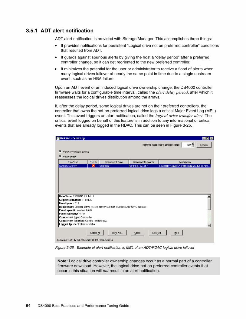
3.5.1 ADT alert notificationADT alert notification is provided with Storage Manager. This accomplishes three things:
� It provides notifications for persistent “Logical drive not on preferred controller” conditions that resulted from ADT.
� It guards against spurious alerts by giving the host a “delay period” after a preferred controller change, so it can get reoriented to the new preferred controller.
� It minimizes the potential for the user or administrator to receive a flood of alerts when many logical drives failover at nearly the same point in time due to a single upstream event, such as an HBA failure.
Upon an ADT event or an induced logical drive ownership change, the DS4000 controller firmware waits for a configurable time interval, called the alert delay period, after which it reassesses the logical drives distribution among the arrays.
If, after the delay period, some logical drives are not on their preferred controllers, the controller that owns the not-on-preferred-logical drive logs a critical Major Event Log (MEL) event. This event triggers an alert notification, called the logical drive transfer alert. The critical event logged on behalf of this feature is in addition to any informational or critical events that are already logged in the RDAC. This can be seen in Figure 3-25.
Figure 3-25 Example of alert notification in MEL of an ADT/RDAC logical drive failover
Note: Logical drive controller ownership changes occur as a normal part of a controller firmware download. However, the logical-drive-not-on-preferred-controller events that occur in this situation will not result in an alert notification.
94 DS4000 Best Practices and Performance Tuning Guide
3.5.2 Failover alert delayThe failover alert delay lets you delay the logging of a critical event if the multipath driver transfers logical drives to the non-preferred controller. If the multipath driver transfers the logical drives back to the preferred controller within the specified delay period, no critical event is logged. If the transfer exceeds this delay period, a logical drive-not-on-preferred-path alert is issued as a critical event. This option also can be used to minimize multiple alerts when many logical drives failover because of a system error, such as a failed host adapter.
The logical drive-not-on-preferred-path alert is issued for any instance of a logical drive owned by a non-preferred controller and is in addition to any other informational or critical failover events. Whenever a logical drive-not-on-preferred-path condition occurs, only the alert notification is delayed; a needs attention condition is raised immediately.
To make the best use of this feature, set the failover alert delay period such that the host driver failback monitor runs at least once during the alert delay period. Note that a logical drive ownership change might persist through the alert delay period, but correct itself before you can inspect the situation. In such a case, a logical drive-not-on-preferred-path alert is issued as a critical event, but the array will no longer be in a needs-attention state. If a logical drive ownership change persists through the failover alert delay period, refer to the Recovery Guru for recovery procedures.
Changing the failover alert delayTo change the failover alert delay:
1. Select the storage subsystem from the Subsystem Management window, and then select either the Storage Subsystem → Change → Failover Alert Delay menu option, or right-click and select Change → Failover Alert Delay. See Figure 3-26.
Important: Here are several considerations regarding failover alerts:
� The failover alert delay option operates at the storage subsystem level, so one setting applies to all logical drives.
� The failover alert delay option is reported in minutes in the Storage Subsystem Profile as a storage subsystem property.
� The default failover alert delay interval is five minutes. The delay period can be set within a range of 0 to 60 minutes. Setting the alert delay to a value of zero results in instant notification of a logical drive not on the preferred path. A value of zero does not mean alert notification is disabled.
� The failover alert delay is activated after controller start-of-day completes to determine if all logical drives were restored during the start-of-day operation. Thus, the earliest that the not-on-preferred path alert will be generated is after boot up and the configured failover alert delay.
Chapter 3. DS4000 configuration tasks 95

Figure 3-26 Changing the failover alert delay
The Failover Alert Delay dialog box opens, as seen in Figure 3-27.
Figure 3-27 Failover Alert Delay dialog box
Enter the desired delay interval in minutes and click OK.
3.5.3 DS4000 Service AlertDS4000 Service Alert is a feature of the IBM TotalStorage DS4000 Storage Manager that monitors system health and automatically notifies the IBM Support Center when problems occur. Service Alert sends an e-mail to a call management center that identifies your system and captures any error information that can identify the problem. The IBM support center analyzes the contents of the e-mail alert and contacts you with the appropriate service action.
96 DS4000 Best Practices and Performance Tuning Guide
Service offering contractTo obtain a service offering contract:
1. The account team submits a request for price quotation (RPQ) requesting Service Alert, using the designated country process.
2. The IBM TotalStorage hub receives the request and ensures that the prerequisites are met, such as these:
– The machine type, model, and serial number are provided.
– The DS4000 Storage Server management station is running Storage Manager Client Version 8.3 or higher.
– The DS4000 Storage Server firmware level is appropriate.
– The DS4000 Storage Server management station has Internet access and e-mail capability.
– Willingness to sign the contract with the annual fee is indicated.
3. After the prerequisites are confirmed, the service offering contract is sent.
4. When the contract has been signed, the approval is sent from the IBM TotalStorage hub, with the support team copied.
5. Billing is sent at the start of the contract.
Activating DS4000 Service AlertTo activate Service Alert, complete the following tasks:
1. Create a user profile (userdata.txt).2. Rename each storage subsystem and synchronize the controller clock.3. Configure the e-mail server.4. Configure the alert destination.5. Validate the installation.6. Test the system.
Creating a user profileThe user profile (userdata.txt) is a text file that contains your individual contact information. It is placed at the top of the e-mail that Service Alert generates. A template is provided, which you can download and edit using any text editor.
Perform the following steps to create the user profile:
1. Download the userdata.txt template file from one of the following Web sites:
http://www-1.ibm.com/servers/storage/support/disk/ds4500/ http://www-1.ibm.com/servers/storage/support/disk/ds4400/ http://www-1.ibm.com/servers/storage/support/disk/ds4300/ http://www-1.ibm.com/servers/storage/support/disk/ds4100/ http://www-1.ibm.com/servers/storage/support/disk/fastt500/http://www-1.ibm.com/servers/storage/support/disk/fastt200/
The userdata.txt template is named userdata.txt.
Important: The user profile file name must be userdata.txt. The file content must be in the format as described in step 2. In addition, the file must be placed in the appropriate directory in the DS4000 Storage Server management station as indicated in step 4.
Chapter 3. DS4000 configuration tasks 97
2. Enter the required information. There should be seven lines of information in the file. The first line should always be “Title: IBM DS4000 Product”. The other lines contain the company name, company address, contact name, contact phone number, alternate phone number, and machine location information. Do not split the information for a given item, for example, do not put the company address on multiple lines. Use only one line for each item.
The Title field of the userdata.txt file must always be “IBM DS4000 Product”. The rest of the fields should be completed for your specific DS4000 Storage Server installation.
See Example 3-1 for an example of a completed userdata.txt user profile.
Example 3-1 Sample userdata.txt
Title: IBM DS4000 Product Company name: IBM (73HA Department) Address: 3039 Cornwallis Road, RTP, NC 27709 Contact name: John Doe Contact phone number: 919-254-0000 Alternate phone number: 919-254-0001 Machine location: Building 205 Lab, 1300
3. Save the userdata.txt file in ASCII format.
4. Store the userdata.txt file in the appropriate subdirectory of the DS4000 Storage Server management station, depending on the operating system that is installed in the management station:
– For Microsoft Windows 2000 and Windows NT4, store the userdata.txt file in the %SystemRoot%\java\ directory if Event Monitor is installed, or if Event Monitor is not installed, in the Installed_Windows_driveletter:\Documents and Settings\Current_login_user_folder directory.
If your Windows 2000 or Windows NT4 installation uses the default installation settings, and the current login user ID is Administrator, the directories are c:\WINNT\java or c:\Documents and Settings\Administrator, respectively.
– For AIX, store the userdata.txt file in the / directory.
– For Red Hat Advanced Server, store the userdata.txt file in the default login directory of the root user. In a normal installation, this directory is /root.
– For SuSE 8, store the userdata.txt file in the default login directory of the root user. In a normal installation, this directory is /root.
– For Novell NetWare, store the userdata.txt file in the sys:/ directory.
– For Solaris, store the userdata.txt file in the / directory.
– For HP-UX, store the userdata.txt file in the / directory.
– VMware ESX servers that are connected to a DS4000 Storage Server require a separate workstation for DS4000 Storage Server management. Service Alert is only supported in a VMware ESX and DS4000 environment by way of the remote management station.
Note: When you type in the text for the userdata.txt file, the colon (:) is the only legal separator between the required label and the data. No extraneous data is allowed (blanks, commas, etc.) in the label unless specified. Labels are not case sensitive.
Note: You must have a Storage Manager Client session running to monitor failures of the DS4000 Storage Server.
98 DS4000 Best Practices and Performance Tuning Guide
Configuring the e-mail serverYou must configure your e-mail server to enable it to send alerts. Refer to 3.5, “Event monitoring and alerts” on page 93 for instructions about how to do this.
The e-mail address you enter is used to send all alerts.
Configuring the alert destinationRefer to 3.5, “Event monitoring and alerts” on page 93 for instructions about how to do this.
In the E-mail address text box, enter either one of the following e-mail addresses, depending on your geographic location:
� For EMEA and A/P locations: [email protected]� For North America locations: [email protected]� For South and Central America, and Caribbean Island locations: [email protected]
Validating the Service Alert installationMake sure that the DS4000 Event Monitor service is installed in the management station. If it is not installed, you must uninstall the DS4000 Storage Manager Client and reinstall it with the Event Monitor service enabled.
Testing the Service Alert installationAfter all previous tasks are completed, you are ready to test your system for Service Alert.
Call your IBM Support Center. Tell the representative that you are ready to test the Service Alert process. The IBM representative will work with you to test your system setup and ensure that DS4000 Service Alert is working properly.
A test that you will perform, with the help of the Support Center, is to manually fail a non-configured drive in the DS4000 Storage Server using the DS4000 Storage Manager Client. If all of the drives are configured, you can turn off a redundant power supply in the DS4000 Storage Server or DS4000 expansion enclosure. When the drive fails or the power supply is turned off, a Service Alert is sent to the IBM e-mail address that you specified in “Configuring the e-mail server” on page 99.
3.5.4 Alert Manager Services The IBM TotalStorage DS4000 Alert Manager is a services solution designed to support the remote monitoring of installed DS4000s, expanding the capability beyond the existing DS4000 Service Alert. It is primarily designed to decrease the time it takes to resolve problems.
Note: The DS4000 Event Monitor service is not supported on Novell Netware 6. You must use a management station with other operating systems installed, such as Windows 2000.
Note: Do not turn off the power supply if this is the only one that is powered on in your storage server or expansion enclosure. Turning off the power supply is the preferred test, because it allows the testing of the DS4000 Storage Server Event Monitor service. This service monitors the DS4000 Storage Server for alerts without needing to have the DS4000 Storage Manager Client running in the root user session.
Note: The DS4000 Alert Manager is made available through the RPQ process.
Chapter 3. DS4000 configuration tasks 99

Alert Manager Services are based on a Call Home Appliance, which allows two-way communication between the DS4000 controller and IBM remote support while reducing problem resolution time for the end user. This appliance is an integrated solution designed to support the remote monitoring of installed DS4000s. It is designed to automatically notify IBM Service when the DS4000 issues an alert. The appliance can monitor up to four DS4000 subsystems via the serial interface (Figure 3-28).
Figure 3-28 Alert Manager Services
With the DS4800, the appliance can connect to the second Ethernet port of the controller instead of using the serial port. In this case up to sixteen DS4800 can be supported.
The appliance is based on an xSeries server with an additional multiport serial interface adapter and internal modem. The modem is used for sending the alert e-mail to the IBM service and for dialing in to the DS4000. IBM Service can electronically contact the appliance (including DS4000 event log files) through the modem connection and request the appliance software to obtain information about the alert. Event log files and additional information are transmitted back to IBM Service, from the appliance, to assist IBM Service with problem determination and problem source identification.
To assure reliable operation of the Alert Manager Services, the customers may choose to have regular heartbeat checks done. IBM Service can periodically call into the appliance in order to verify the modem connectivity.
You should prevent any unauthorized access to the DS4000 Storage Servers. We therefore suggest using all the available security features:
Note: For security reasons, the Ethernet attachment to the appliance is only supported with the DS4800 because it has a second separate Ethernet port on each controller. In this case, the appliance remains isolated from the network used to manage the DS4800.
100 DS4000 Best Practices and Performance Tuning Guide

� Set the password for the DS4000 Storage Server.
� The shell commands are potentially destructive, and we therefore suggest that you prevent access to the controller shell.
� The appliance itself has two passwords. The first password protects the access to the appliance. After four invalid attempts, the modem connection is dropped.
The second password secures access to the DS4000 logs and configuration-related tasks. This password is changed each month during the heartbeat checks.
� When IBM support dials into the appliance to obtain the DS4000 Storage Server logs and status, you have two possibilities:
– Automatically allow access.
– Require that the IBM support call you first and ask you for permission. This option is obviously more secure, and we suggest you to use it.
With regard to the security, it is important to know that the appliance is not connected to the customer’s intranet, and it also does not have any customer-accessible interfaces or controls.
The Alert Manager Services do not require Storage Manager Version 9.14. They will also work with older versions of Storage Manager (Version 8.3 or later).
3.6 Software and microcode upgradesEvery so often IBM will release new firmware (it is posted on the support the Web site) that will need to be installed. Occasionally, IBM may remove old firmware versions from support. Upgrades from unsupported levels are mandatory to receive warranty support.
This section reviews the required steps to upgrade your IBM TotalStorage DS4000 Storage Server when firmware updates become available. Upgrades to the DS4000 Storage Server firmware should generally be preceded by an upgrade to the latest available version of the Storage Manager client software as this may be required to access the DS4000 Storage Server when the firmware upgrade completes. In most cases, it is possible to manage a DS4000 Storage Server running down-level firmware with the latest SMclient, but not possible to manage a Storage Server running the latest version of firmware with a down-level client. In some cases the only management capability provided may be to upgrade the firmware to newer level; which is the desired goal.
3.6.1 Staying up-to-date with your drivers and firmware using My supportMy support registration provides E-mail notification when new firmware levels have been updated and are available for download and installation. To register for My support, visit:
http://www.ibm.com/support/mysupport/us/en
Following is the registration process:
� The Sign In window displays:
– If you have a valid IBM ID and Password, then sign in.
Note: The version number of the Storage Manager firmware and the Storage Manager client are not completely connected. For example; Storage Manager 9.15x can manage storage servers which are running storage server firmware 5.3x on them. Always check the readme file for details of latest storage manager release and special usage.
Chapter 3. DS4000 configuration tasks 101

– If you are not currently registered with the site, click Register now and register your details.
� The My Support window opens. Click Add Products to add products to your profile.
� Use the pull-down menus to choose the appropriate DS4000 storage server and expansion enclosures that you want to add to your profile.
� To add the product to your profile, select the appropriate box or boxes next to the product names and click Add Product.
� Once the product or products are added to your profile, click the Subscribe to Email folder tab.
� Select Storage in the pull down menu. Select Please send these documents by weekly email and select Downloads and drivers and Flashes to receive important information about product updates. Click Updates.
� Click Sign Out to log out of My Support.
You will be notified whenever there is new firmware available for the products you selected during registration.
We also suggest that you explore and customize to your needs the other options available under My support.
3.6.2 Prerequisites for upgradesUpgrading the firmware and management software for the DS4000 Storage Server is a relatively simple procedure. Before you start, you should make sure that you have an adequate maintenance window to do the procedure, because on large configurations it can be a little time consuming. The times for upgrading all the associated firmware and software are in Table 3-2. These times are only approximate and can vary from system to system.
Table 3-2 Upgrade times
It is critical that if you update one part of the firmware, you update all the firmware and software to the same level. You must not run a mismatched set.
All the necessary files for performing this upgrade are available at:
http://www.ibm.com/pc/support/site.wss/document.do?lndocid=MIGR-4JTS2T
Look for “TotalStorage / Fibre Channel Solutions”.
3.6.3 Updating the controller microcodeWe recommend that your DS4000 Storage Server always be at a recent level of microcode. Occasionally, IBM will withdraw older levels of microcode from support. In this case, an upgrade to the microcode is mandatory. In general, you should plan on upgrading all drivers, microcode, and management software in your SAN on a periodic basis. New code levels may contain important fixes to problems you may not have encountered yet.
Element being upgraded Approximate time of upgrade
Storage Manager software and associated drivers and software 35 minutes
DS4000 Storage Server firmware 5 minutes
DS4000 ESM firmware 5 minutes per ESM
Hard drives 3 minutes per drive type
102 DS4000 Best Practices and Performance Tuning Guide

The microcode of the DS4000 Storage Server consists of two packages:
� The firmware� The NVSRAM package, including the settings for booting the DS4000 Storage Server
The NVSRAM is similar to the settings in the BIOS of a host system. The firmware and the NVSRAM are closely tied to each other and are therefore not independent. Be sure to install the correct combination of the two packages.
The upgrade procedure needs two independent connections to the DS4000 Storage Server, one for each controller. It is not possible to perform a microcode update with only one controller connected. Therefore, both controllers must be accessible either via Fibre Channel or Ethernet. Both controllers must also be in the active state.
If you plan to upgrade via Fibre Channel, make sure that you have a multipath I/O driver installed on your management host. In most cases, this would be the RDAC. This is necessary since access logical drive moves from one controller to the other during this procedure and the DS4000 Storage Server must be manageable during the entire time.
Staged microcode upgradeStaged microcode upgrade was introduced with the Storage Manager 9.10 and firmware 6.10. You can load the controller firmware and NVSRAM to a designated flash area on the DS4000 controllers and activate it at a later time. Of course, you can still transfer the controller microcode to the Storage Subsystem and activate it in one step if necessary.
The firmware is transferred to one of the controllers. This controller copies the image to the other controller. The image is verified through a CRC check on both controllers. If the checksum is OK, the uploaded firmware is marked ready and available for activation. If one of the two controllers fails to validate the CRC, the image is marked invalid on both controllers and not available for activation. An error is returned to the management station as well.
Important: Before upgrading the Storage Server firmware and NVSRAM, make sure that the system is in an optimal state. If not, run the Recovery Guru to diagnose and fix the problem before you proceed with the upgrade.
Important: Here are some considerations for your upgrade:
� Refer to the readme file to find out which between the ESM or the controllers must be upgraded first. In some cases, the expansion enclosure ESMs must be updated to the latest firmware level before starting the controller update (outdated ESM firmware could make your expansion enclosures inaccessible after the DS4000 Storage Server firmware update). In some cases it is just the opposite.
� Update the controller firmware and then the NVSRAM.
� Ensure that all hosts attached to the DS4000 Storage Server have a multipath I/O driver installed.
� Any power or network/SAN interruption during the update process may lead to configuration corruption. Therefore, do not power off the DS4000 Storage Server or the management station during the update. If you are using in-band management and have Fibre Channel hubs or managed hubs, then make sure no SAN connected devices are powered up during the update. Otherwise, this can cause a loop initialization process and interrupt the process.
Chapter 3. DS4000 configuration tasks 103
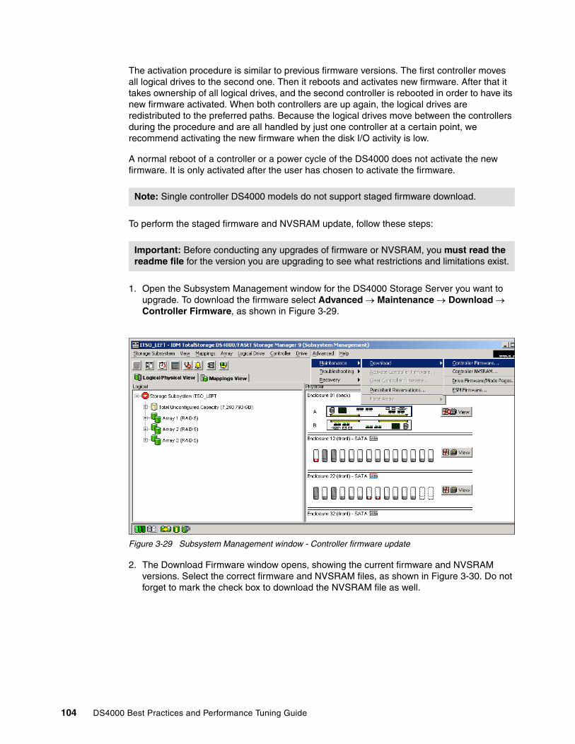
The activation procedure is similar to previous firmware versions. The first controller moves all logical drives to the second one. Then it reboots and activates new firmware. After that it takes ownership of all logical drives, and the second controller is rebooted in order to have its new firmware activated. When both controllers are up again, the logical drives are redistributed to the preferred paths. Because the logical drives move between the controllers during the procedure and are all handled by just one controller at a certain point, we recommend activating the new firmware when the disk I/O activity is low.
A normal reboot of a controller or a power cycle of the DS4000 does not activate the new firmware. It is only activated after the user has chosen to activate the firmware.
To perform the staged firmware and NVSRAM update, follow these steps:
1. Open the Subsystem Management window for the DS4000 Storage Server you want to upgrade. To download the firmware select Advanced → Maintenance → Download → Controller Firmware, as shown in Figure 3-29.
Figure 3-29 Subsystem Management window - Controller firmware update
2. The Download Firmware window opens, showing the current firmware and NVSRAM versions. Select the correct firmware and NVSRAM files, as shown in Figure 3-30. Do not forget to mark the check box to download the NVSRAM file as well.
Note: Single controller DS4000 models do not support staged firmware download.
Important: Before conducting any upgrades of firmware or NVSRAM, you must read the readme file for the version you are upgrading to see what restrictions and limitations exist.
104 DS4000 Best Practices and Performance Tuning Guide

Figure 3-30 Download Firmware window
There is another check box at the bottom of the window (Transfer files but do not activate them). Mark this check box if you want to activate the new firmware at a later time. Then click OK to continue.
3. The next window instructs you to confirm the firmware and NVSRAM download (because the process cannot be cancelled once it begins).
Confirm by clicking Yes. The firmware/NVSRAM transfer begins and you can watch the progress. When the process finishes, the Transfer Successful message is displayed, as shown in Figure 3-31.
Figure 3-31 Firmware/NVSRAM download finished
Chapter 3. DS4000 configuration tasks 105

4. After clicking Close, you are back in the Subsystem Management window. Because this is a staged firmware upgrade, the new firmware is now ready for activation. This is indicated by an icon (blue 101) next to the Storage Subsystem name (as shown in Figure 3-32).
Figure 3-32 Subsystem Management window - Firmware ready for activation
5. To activate the new firmware, select Advanced → Maintenance → Activate Controller Firmware, as shown in Figure 3-33.
Figure 3-33 Subsystem Management window - Firmware activation
The Activate Firmware window opens and asks you for confirmation that you want to continue. After you click Yes, the activation process starts. You can monitor the progress in the Activation window, as shown in Figure 3-34.
106 DS4000 Best Practices and Performance Tuning Guide
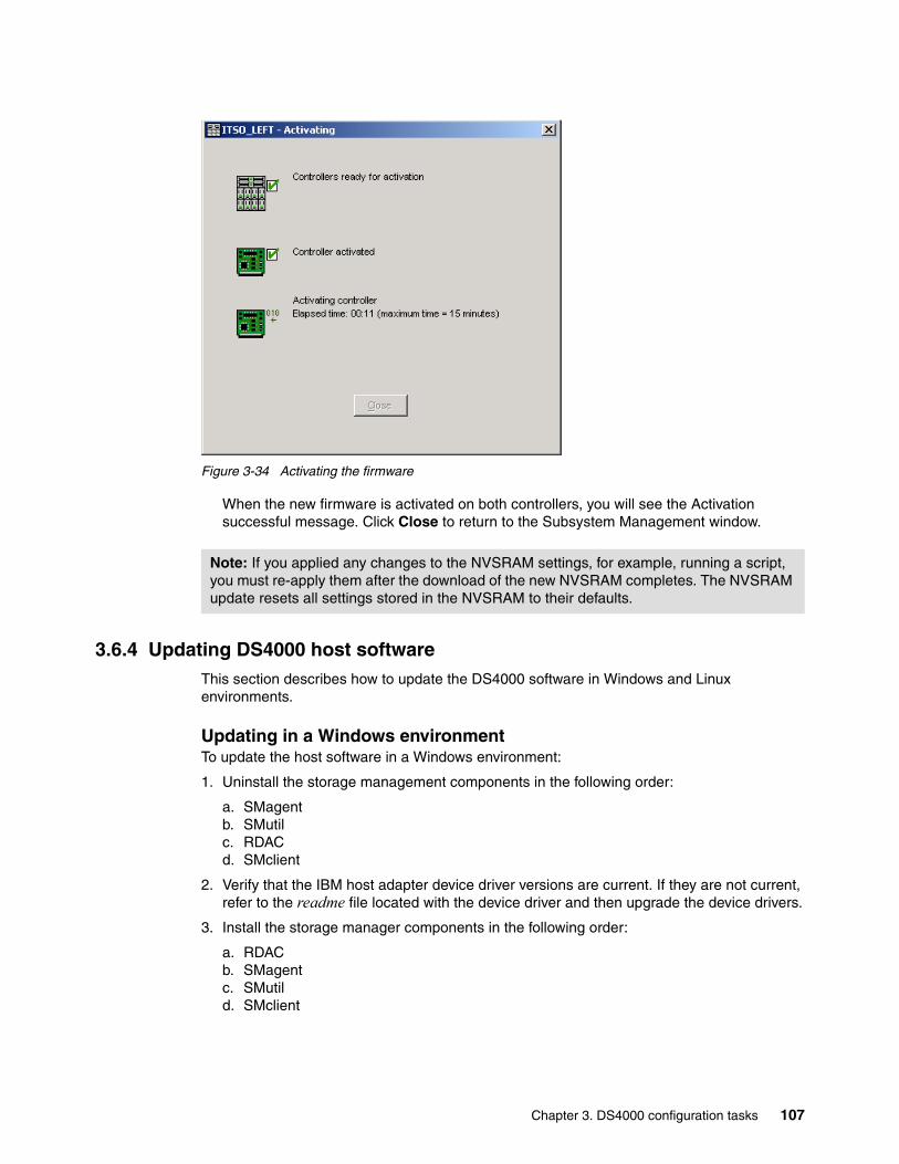
Figure 3-34 Activating the firmware
When the new firmware is activated on both controllers, you will see the Activation successful message. Click Close to return to the Subsystem Management window.
3.6.4 Updating DS4000 host softwareThis section describes how to update the DS4000 software in Windows and Linux environments.
Updating in a Windows environmentTo update the host software in a Windows environment:
1. Uninstall the storage management components in the following order:
a. SMagentb. SMutilc. RDACd. SMclient
2. Verify that the IBM host adapter device driver versions are current. If they are not current, refer to the readme file located with the device driver and then upgrade the device drivers.
3. Install the storage manager components in the following order:
a. RDACb. SMagentc. SMutild. SMclient
Note: If you applied any changes to the NVSRAM settings, for example, running a script, you must re-apply them after the download of the new NVSRAM completes. The NVSRAM update resets all settings stored in the NVSRAM to their defaults.
Chapter 3. DS4000 configuration tasks 107
Updating in a Linux environmentTo update the host software in a Linux environment:
1. Uninstall the storage manager components in the following order:
a. DS4000 Runtime environmentb. SMutilc. RDACd. SMclient
2. Verify that the IBM host adapter device driver versions are current. If they are not current, refer to the readme file located with the device driver and then upgrade the device drivers.
3. Install the storage manager components in the following order:
a. SMagentb. DS4000 Runtime environment\c. RDACd. SMutile. SMclient
3.7 Capacity upgrades, system upgradesThe DS4000 has the ability to accept new disks and/or EXP units dynamically, with no downtime to the DS4000 unit. In fact, the DS4000 must be powered on when adding new hardware.
3.7.1 Capacity upgrades and increased bandwidthWith the DS4000 Storage Server you can add capacity by adding expansion enclosures or disks to the enclosure being used. Care must be taken when performing these tasks to avoid damaging the configuration currently in place. For this reason you must follow the detailed steps laid out for each part.
For further recommendations on cabling and layout, see the specific section for the DS4000 Storage Server you are working with.
After physical installation, use Storage Manager to create new arrays/LUNs, or extend existing arrays/LUNs. (Note that some operating systems may not support dynamic LUN expansion.)
Note: In pre-9.1x versions the SMagent was not used so was not needed to be deinstalled.
Important: Prior to physically installing new hardware, refer to the instructions in the Fibre Channel Hard Drive and Storage Expansion Enclosure Installation and Migration Guide, GC26-7639, available at:
http://www.ibm.com/support/docview.wss?uid=psg1MIGR-55466
Failure to consult this documentation may result in data loss, corruption, or loss of availability to your storage.
108 DS4000 Best Practices and Performance Tuning Guide

3.7.2 Storage server upgrade and disk migration proceduresThe procedures to migrate disks and enclosures or upgrade to a newer DS4000 controller are not particularly difficult, but care must be taken to ensure that data is not lost. The checklist for ensuring data integrity and the complete procedure for performing capacity upgrades or disk migration is beyond the scope of this book. Users MUST consult the Fibre Channel Hard Drive and Storage Expansion Enclosure Installation and Migration Guide, GC26-7639, available at:
http://www-1.ibm.com/support/docview.wss?uid=psg1MIGR-55466
Here, we explain the DS4000 feature that makes it easy for upgrading subsystems and moving disk enclosures. This feature is known as DACstore.
What is DACstore?DACstore is an area on each drive in a DS4000 storage subsystem or expansion enclosure where configuration information is stored. This 512MB reservation (as pictured in Figure 3-35 on page 109) is invisible to a user and contains information about the DS4000 configuration.
Figure 3-35 The DACstore area of a DS4000 disk drive
The standard DACstore on every drive stores:
� Drive state and status� WWN of the DS4000 controller (A or B) behind which the disk resides� Logical drives contained on the disk
Some drives also store extra global controller and subsystem level information, these are called sundry drives. The DS4000 controllers will assign one drive in each array as a sundry drive, although there will always be a minimum of three sundry drives even if only one or two arrays exist.
Additional information stored in the DACstore region of the sundry drive:
� Failed drive information� Global Hot Spare state/status� Storage subsystem identifier (SAI or SA Identifier)� SAFE Premium Feature Identifier (SAFE ID)� Storage subsystem password� Media scan rate� Cache configuration of the storage subsystem� Storage user label
Chapter 3. DS4000 configuration tasks 109
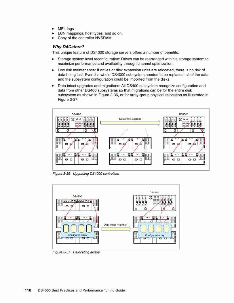
� MEL logs� LUN mappings, host types, and so on.� Copy of the controller NVSRAM
Why DACstore?This unique feature of DS4000 storage servers offers a number of benefits:
� Storage system level reconfiguration: Drives can be rearranged within a storage system to maximize performance and availability through channel optimization.
� Low risk maintenance: If drives or disk expansion units are relocated, there is no risk of data being lost. Even if a whole DS4000 subsystem needed to be replaced, all of the data and the subsystem configuration could be imported from the disks.
� Data intact upgrades and migrations: All DS400 subsystem recognize configuration and data from other DS400 subsystems so that migrations can be for the entire disk subsystem as shown in Figure 3-36, or for array-group physical relocation as illustrated in Figure 3-37.
Figure 3-36 Upgrading DS4000 controllers
Figure 3-37 Relocating arrays
110 DS4000 Best Practices and Performance Tuning Guide
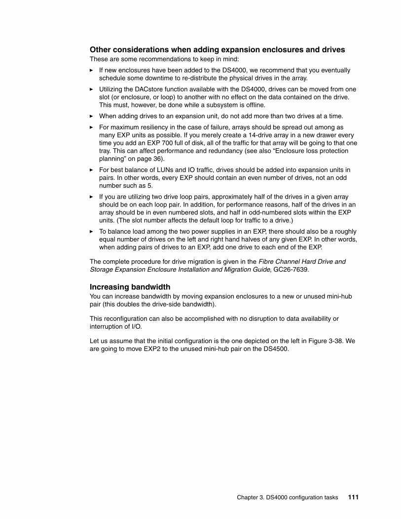
Other considerations when adding expansion enclosures and drivesThese are some recommendations to keep in mind:
� If new enclosures have been added to the DS4000, we recommend that you eventually schedule some downtime to re-distribute the physical drives in the array.
� Utilizing the DACstore function available with the DS4000, drives can be moved from one slot (or enclosure, or loop) to another with no effect on the data contained on the drive. This must, however, be done while a subsystem is offline.
� When adding drives to an expansion unit, do not add more than two drives at a time.
� For maximum resiliency in the case of failure, arrays should be spread out among as many EXP units as possible. If you merely create a 14-drive array in a new drawer every time you add an EXP 700 full of disk, all of the traffic for that array will be going to that one tray. This can affect performance and redundancy (see also “Enclosure loss protection planning” on page 36).
� For best balance of LUNs and IO traffic, drives should be added into expansion units in pairs. In other words, every EXP should contain an even number of drives, not an odd number such as 5.
� If you are utilizing two drive loop pairs, approximately half of the drives in a given array should be on each loop pair. In addition, for performance reasons, half of the drives in an array should be in even numbered slots, and half in odd-numbered slots within the EXP units. (The slot number affects the default loop for traffic to a drive.)
� To balance load among the two power supplies in an EXP, there should also be a roughly equal number of drives on the left and right hand halves of any given EXP. In other words, when adding pairs of drives to an EXP, add one drive to each end of the EXP.
The complete procedure for drive migration is given in the Fibre Channel Hard Drive and Storage Expansion Enclosure Installation and Migration Guide, GC26-7639.
Increasing bandwidthYou can increase bandwidth by moving expansion enclosures to a new or unused mini-hub pair (this doubles the drive-side bandwidth).
This reconfiguration can also be accomplished with no disruption to data availability or interruption of I/O.
Let us assume that the initial configuration is the one depicted on the left in Figure 3-38. We are going to move EXP2 to the unused mini-hub pair on the DS4500.
Chapter 3. DS4000 configuration tasks 111
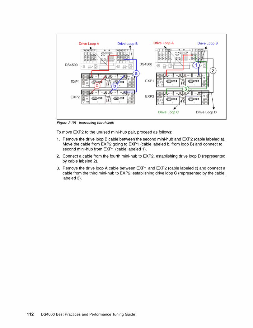
Figure 3-38 Increasing bandwidth
To move EXP2 to the unused mini-hub pair, proceed as follows:
1. Remove the drive loop B cable between the second mini-hub and EXP2 (cable labeled a). Move the cable from EXP2 going to EXP1 (cable labeled b, from loop B) and connect to second mini-hub from EXP1 (cable labeled 1).
2. Connect a cable from the fourth mini-hub to EXP2, establishing drive loop D (represented by cable labeled 2).
3. Remove the drive loop A cable between EXP1 and EXP2 (cable labeled c) and connect a cable from the third mini-hub to EXP2, establishing drive loop C (represented by the cable, labeled 3).
112 DS4000 Best Practices and Performance Tuning Guide

Chapter 4. DS4000 performance tuning
In this chapter we describe and discuss performance topics as they apply to the DS4000 Storage Servers.
It must be understood that the storage server itself is but a piece of the performance puzzle. However, we are focused here on the DS4000 Storage Server’s role. We discuss the different workload types generally observed in storage. their impact on performance and how it can be addressed by the configuration and parameters.
With all DS4000 Storage Servers, good planning and data layout can make the difference between having excellent workload and application performance, and having poor workload, with high response times resulting in poor application performance. It is therefore not surprising that first-time DS4000 clients ask for advice on how to optimally layout their DS4000 Storage Servers.
This chapter covers the following areas:
� Understanding workload � Solution wide considerations� Host considerations� Application considerations� DS4000 Storage Server considerations� Performance data analysis� DS4000 tuning
4
© Copyright IBM Corp. 2005, 2006. All rights reserved. 113

4.1 Workload typesIn general, there are two types of data workload (processing) that can be seen:
� transaction based � throughput based
These two workloads are very different in their nature, and must be planned for in quite different ways. Knowing and understanding how your host servers and applications handle their workload is an important part of being successful with your storage configuration efforts, and the resulting performance of the DS4000 Storage Server.
To best understand what is meant by transaction based and throughput based, we must first define a workload. The workload is the total amount of work that is performed at the storage server, and is measured through the following formula:
Workload = [transactions (number of host IOPS)] * [ throughput (amount of data sent in one IO)]
Knowing that a storage server can sustain a given maximum workload (see Figure 4-5 on page 129 and Figure 4-6 on page 130), we can see with the above formula that if the number of host transactions increases, then the throughput must decrease. Conversely, if the host is sending large volumes of data with each I/O, the number of transactions must decrease.
A workload characterized by a high number of transactions (IOPS) is called a transaction based workload. A workload characterized by large I/Os is called throughput based workload.
These two workload types are conflicting in nature, and consequently will require very different configuration settings across all the pieces of the storage solution. Generally, I/O (and therefore application) performance will be best when the I/O activity is evenly spread across the entire I/O subsystem.
But first, let us describe each type in greater detail, and explain what you can expect to encounter in each case.
Transaction based processes (IOPS)High performance in transaction based environments cannot be created with a low cost model (with a small number of physical drives) of a storage server. Indeed, transaction process rates are heavily dependent on the number of back-end drives that are available for the controller to use for parallel processing of the hosts I/Os. This frequently results in a decision to be made: Just how many drives will be good enough?
Generally, transaction intense applications also use a small random data block pattern to transfer data. With this type of data pattern, having more back-end drives enables more host I/Os to be processed simultaneously, as read cache is far less effective, and the misses need to be retrieved from disk.
In many cases, slow transaction performance problems can be traced directly to “hot” files that cause a bottleneck on some critical component (such as a single physical disk). This situation can occur even when the overall storage server is seeing a fairly light workload. When bottlenecks occur, they can present a very difficult and frustrating task to resolve. As workload content can be continually changing throughout the course of the day, these bottlenecks can be very mysterious in nature and appear and disappear or move over time from one location to another.
Generally, I/O (and therefore application) performance will be best when the I/O activity is evenly spread across the entire I/O subsystem.
114 DS4000 Best Practices and Performance Tuning Guide

Throughput based processes (MB/sec)Throughput based workloads are seen with applications or processes that require massive amounts of data sent, and generally use large sequential blocks to reduce disk latency. Generally, only a small number of drives (20 - 28) are needed to reach maximum throughput rates with the DS4000 Storage Servers. In this environment, read operations make use of the cache to stage greater chunks of data at a time, to improve the overall performance. Throughput rates are heavily dependent on the storage server’s internal bandwidth. Newer storage servers with broader bandwidths are able to reach higher numbers and bring higher rates to bear.
Why should we care?With the DS4000 Storage Server, these two workload types have different parameter settings that are used to optimize their specific workload environments. These settings are not limited to strictly the storage server, but span the entire solution being used. With care and consideration, it is possible to create an environment of very good performance with both workload types and sharing the same DS4000 Storage Server. However, it must be understood that portions of the storage server configuration will be tuned to better serve one workload or the other.
For maximum performance of both workloads, we recommend considering two separate smaller storage servers each tuned for their specific workload, rather than one large server being shared, but this model is not always financially feasible.
4.2 Solution wide considerations for performanceConsidering the different pieces of the solution that can impact performance, we first look at the host and the operating systems settings, as well as how volume managers come into play. Then we look at the applications; what their workload is like, as well as how many different types of data patterns they may have to use and that you must plan for.
Of course, we also look at the DS4000 Storage Server and the many parameter settings that should be considered, according to the environment where the Storage Server is deployed. And finally, we look at specific SAN settings that can affect the storage environment as well.
When looking at performance, one must first consider the location. This is a three phase consideration, consisting of:
1. Looking at the location of the drive/logical drive with regards to the path the host uses to access the logical drive. This encompasses the host volume manager, HBA, SAN fabric, and the storage server controller used in accessing the logical drive. Many performance issues stem from mis-configured settings in these areas.
2. Looking at the location of the data within the storage server on its configured array and logical drive. Check that the array has been laid out to give best performance, and the RAID type is the most optimum for the type of workload. Also, if multiple logical drives reside in the same array, check for interference from other logical drive members when doing their workload.
3. Looking at the location of the data on the back-end drives which make up the array, and how the data is carved up (segmented and striped) across all the members of the array. This includes the number of drives being used, as well as their size, and speed. This area can have a great deal of impact that is very application specific, and usually requires tuning to get to the best results.
We consider each of these areas separately in the following sections.
Chapter 4. DS4000 performance tuning 115
4.3 Host considerationsWhen discussing performance, we need to consider far more than just the performance of the I/O workload itself. Many settings within the host frequently affect the overall performance of the system and its applications. All areas should be checked to ensure we are not focusing on a result rather than the cause. However, in this book we are focusing on the I/O subsystem part of the performance puzzle; so we will discuss items that affect its operation.
Some of the settings and parameters discussed in this section are defined and must match both for the host operating system and for the HBAs which are being used as well. Many operating systems have built-in definitions that can be changed to enable the HBAs to be set to the new values. In this section we try to cover these with AIX, and Windows operating systems as an illustration.
4.3.1 Host based settingsSome host operating systems can set values for the DS4000 Storage server logical drives assigned to them. For instance, some hosts can change the write cache and the cache read-ahead values through attribute settings. These settings can affect both the transaction and throughput workloads. Settings that affect cache usage can have a great impact in most environments.
Other host device attributes that can affect high transaction environments are those affecting the blocksize, and queue depth capabilities of the logical drives.
� The blocksize value used by the host IO helps to determined the best segment size choice. We recommend that the segment size be set to at least twice the size of the IO blocksize being used by the host for the high transaction workload.
� The queue depth value cannot exceed the storage server maximum of 2048 for DS4000 storage servers running firmware 6.1x and later; and a maximum of 512 for firmware 5.3x and 5.4x. All logical drives on the storage server must share these queue limits. Some hosts define the queue depth only at the HBA level, while others may also define this limit at the storage device level, which ties to the logical drive. The following formulas can be used to determine a good starting point for your queue depth value on a per logical drive basis:
For firmware level 6.1x and higher: 2048 / (number-of-hosts * logical drives-per-host), and for firmware level 5.3 and 5.4: 512 / (number-of-hosts * logical drives-per-host)
As an example: A storage server with 4 hosts with 12, 14, 16 and 32 logical drives attached respectively would be calculated as follows:
2048 / 4 * 32 (largest number of logical drives per host) = 16512 / 4 * 32 (largest number of logical drives per host) = 4
If configuring only at the HBA level, you can use the formula: 2048 / ( total number-of-HBA’s ), and 512 / ( total number-of-HBAs ) for the respective firmware levels.
In the high throughput environments, you should try to use a host IO blocksize that is equal to, or an even multiple of the stripe width of the logical drive being used.
Also, we are interested in settings that affect the large IO blocksize, and settings mentioned earlier that may force a cache read-ahead value.
Important: Setting queue depth too high can result in loss of data and possible file corruption; therefore, being conservative with these settings is better.
116 DS4000 Best Practices and Performance Tuning Guide
Additionally, you will want to ensure that the cache read-ahead value is enabled. This function is discussed in detail later in this chapter; but some operating system environments may have a variable value for changing this through device settings. Using the DS4000 to change this setting is the recommended method.
Finally, there are settings that may also impact performance with some servers and HBA types that enhance FC tape support. This setting should not be used with FC disks attached to the HBA.
Host data layoutEnsure the host operating system aligns its device data partitions or slices, with those of the logical drive. Misalignment can result in numerous boundary crossings which are responsible for unnecessary multiple drive IOs. Some operating systems do this automatically, and you just need to know the alignment boundary they use. Others however, may require manual intervention to set their start point to a value which would align them.
Understanding how your host based volume manager (if used) defines, and makes use of the logical drives once they are presented is also an important part of the data layout. As an example, the AIX Logical Volume Manager (LVM) is discussed in Section 2.5.1, “Planning for systems with LVM: AIX example” on page 53).
Volume managers are generally setup to place logical drives into usage groups for their use. The volume manager then creates volumes by carving up the logical drives into partitions (sometimes referred to as a slice); and then building a volume from them by either striping, or concatenating them to form the volume size desired. How the partitions are selected for use, and laid out may vary from system to system. In all cases, you need to ensure that spreading of the partitions is done in a manner to achieve maximum IOs available to the logical drives in the group. Generally, large volumes are built across a number of different logical drives to bring more resources to bear. The selection of logical drives when doing this should be made carefully as not to use logical drives which will compete for resources, and degrade performance. The following are some general basic rules to apply.
� In a RAID 1 (0r RAID 10) environment, these logical drives can be from the same array; but must be preferred path through different controllers for greater bandwidth and resource utilization.
� For RAID 5, these logical drives should be on separate arrays, and preferred path through different controllers. This will ensure that the logical drives will not be in conflict with each other when the volume is used and both slices are accessed.
� If striping is used, ensure that the stripe size chosen is a value that is complementing the size of the underlying stripe width defined for the logical drives (see “Logical drive segments” on page 139). The value used here will be dependent on the application and host IO workload that will be using the volume. If the stripe width can be configured to sizes that complement the logical drives stripe; then benefits can be seen with using it. In
Best Practice: Though it is supported in theory, we strongly recommend that you keep Fibre Channel tape and Fibre Channel disks on separate HBAs. These devices have two very different data patterns when operating in their optimum mode, and the switching between them can cause undesired overhead and performance slowdown for the applications.
Best Practice: For best performance, when building (host) volumes from logical drives, use logical drives from different arrays, with the preferred paths evenly spread among the two controllers of the DS4000 Storage Server.
Chapter 4. DS4000 performance tuning 117

most cases this model requires larger stripe values and careful planning to properly implement.
The exception to this would be for single threaded application processes with sequential IO streams that have a high throughput requirement. In this case a small LVM stripe size of 64K or 128K can allow for the throughput to be spread across multiple logical drives on multiple arrays and controllers, spreading that single IO thread out, and potentially giving you better performance. This model is generally not recommended for most workloads as the small stripe size of LVM can impair the DS4000 ability to detect and optimize for high sequential IO workloads.
With filesystems you again will want to revisit the need to ensure that they are aligned with the volume manager or the underlying RAID. Frequently, an offset is needed to ensure that the alignment is proper. Focus here should be to avoid involving multiple drives for a small IO request due to poor data layout. Additionally, with some operating systems you can encounter interspersing of file index (aka inode) data with the user data, which can have a negative impact if you have implemented a full stripe write model. To avoid this issue you may wish to use raw devices (volumes) for full stripe write implementations.
4.3.2 Host setting examplesThe following are example settings that may be used to start off your configuration in the specific workload environment. Those settings are suggested, they are not guaranteed to be the answer to all configurations. You should always try to setup a test of your data with your configuration to see if there is some further tuning that may better help (see recommended methods and tools in Chapter 6, “Analyzing and measuring performance” on page 165). Again, knowledge of your specific data IO pattern is extremely helpful.
AIX operating system settingsThe following section outlines the settings that can affect performance on an AIX host. We look at these in relations to how they impact the two different workload types.
Transaction settingsEarly AIX driver releases allowed for the changing of the cache read-ahead through the logical drive attribute settings; this has been discontinued with current releases, and is now set by the DS4000 Storage Server value, and can now only report the value from the operating system.
All attribute values that are changeable can be changed using the chdev command for AIX. See the AIX manpages for details on the usage of chdev.
For the logical drive known as the hdisk in AIX, the setting is the attribute queue_depth.
# chdev -l hdiskX -a queue_depth=Y -P
In the above example “X” is the hdisk number, and “Y” is the value for queue_depth you are setting it to.
For the HBA settings, the attribute num_cmd_elem for the fcs device is used. This value should not exceed 512.
chdev -l fcsX -a num_cmd_elem=256 -P
Best Practice: For high transactions on AIX, we recommend that you set num_cmd_elem to 256 for the fcs devices being used.
118 DS4000 Best Practices and Performance Tuning Guide
Throughput based settingsIn the throughput based environment, you would want to decrease the queue depth setting to a smaller value such as 16. In a mixed application environment, you would not want to lower the “num_cmd_elem” setting, as other logical drives may need this higher value to perform. In a pure high throughput workload, this value will have no effect.
AIX settings which can directly affect throughput performance with large IO blocksize are the lg_term_dma, and max_xfer_size parameters for the fcs device.
Note that setting the max_xfer_size affects the size of a memory area used for data transfer by the adapter. With the default value of max_xfer_size=0x100000, the area is 16 MB in size, and for other allowable values of max_xfer_size, the memory area is 128 MB in size.
See also 7.1.7, “Setting the HBA for best performance” on page 241.
AIX LVM impactAIX uses Logical Volume Manager (LVM) to manage the logical drives and physical partitions. By default, with standard and big VGs, LVM reserves the first 4K of the volume for the Logical Volume Control Block. Therefore, the first data block will start at an offset of 4K into the volume. Care should be taken when laying out the segment size of the logical drive to enable the best alignment. You can eliminate the Logical Volume Control Block on the LV by using a scalable VG, or by using the -T 0 option for big VGs.
Additionally, in AIX, filesystems are aligned on a 16K boundary. Remembering these two items helps when planning for AIX to fit well with the DS4000 segment size. JFS and JFS2 filesystems intersperse inode data with the actual user data, and can potentially disrupt the full stripe write activity. To avoid this issue, you can place files with heavy sequential writes on raw logical volumes. See also the recommendations defined in “Logical drive segments” on page 139.
With AIX LVM, it is generally recommended to spread high transaction logical volumes across the multiple logical drives that you have chosen, using the maximum interpolicy setting (also known as maximum range of physical volumes) with a random ordering of PVs for each LV. Ensure that your logical drive selection is done as recommended above, and is appropriate for the RAID type selected.
In environments with very high rate, sequentially accessed structures and a large IO size, try to make the segment size times the (N-1 for RAID 5, or N/2 for RAID 10) to be equal to the application IO size. And keep the number of sequential IO streams per array to be less than the number of disks in the array.
Windows operating system settingsIn this section we discuss settings for performance with the Windows operating system and the DS4000 Storage Server. Topics include:
� Fabric settings� Disk types� Disk alignment� Allocation unit size
Best Practice: The recommended start values for high throughput sequential IO environments are: lg_term_dma = 0x800000, and max_xfr_size = 0x200000.
Chapter 4. DS4000 performance tuning 119
Fabric settingsWith Windows operating systems, the queue depth settings are the responsibility of the host adapters, and configured through the BIOS setting. This varies from vendor to vendor: Refer to your manufacturer’s instructions on how to configure your specific cards.
For the IBM FAStT FC2-133 (and Qlogic based HBAs), the queue depth is known as execution throttle, which can be set with either the FAStT MSJ tool, or in the BIOS of the Qlogic based HBA, by pressing CTL+Q during the boot process.
Disk typesWith Windows 2000 and Windows 2003, there are two types of disks, basic disks and dynamic disks. By default, when a Windows system is installed, the basic disk system is used. Disks can be changed from basic to dynamic at anytime without impact on system or data.
Basic disks use partitions. These partitions in Windows 2000 are set to the size they were created. For Windows 2003, a primary partition on a basic disk can be extended using the extend command in the diskpart.exe utility.
In Windows 2000 and 2003, dynamic disks allow for expansion, spanning, striping, software mirroring, and software RAID 5.
With the DS4000 Storage Server, you can use either basic or dynamic disks. The appropriate type depends on your individual circumstances:
� In certain large installations where you may have the requirement to span or stripe logical drives and controllers to balance the workload, then dynamic disk may be your only choice.
� For smaller to mid-size installations, you may be able to simplify and just use basic disks.
When using the DS4000 as the storage system, the use of software mirroring and software RAID 5 is not required. Instead, configure the storage on the DS4000 storage server for the redundancy level required.
Basic disksBasic disks and basic volumes are the storage types most often used with Windows operating systems. Basic disk is the default disk type during initial installation. A basic disk refers to a disk that contains basic volumes, such as primary partitions and logical drives. A basic volume refers to a partition on a basic disk. Basic disks are used in both x86-based and Itanium-based computers.
Basic disks support clustered disks. Basic disks do not support spanning, striping, mirroring and software level RAID 5. To use this functionality, you must convert the basic disk to a dynamic disk. If you want to add more space to existing primary partitions and logical drives, you can extend the volume using the extend command in the diskpart utility.
Here is the syntax for the diskpart utility to extend the disk:
Extend [size=n] [disk=n] noerrWhere:
size=nThe space in megabytes to add to the current partition. If you do not specify one it will take up all the unallocated space of that disk.
disk=n
120 DS4000 Best Practices and Performance Tuning Guide
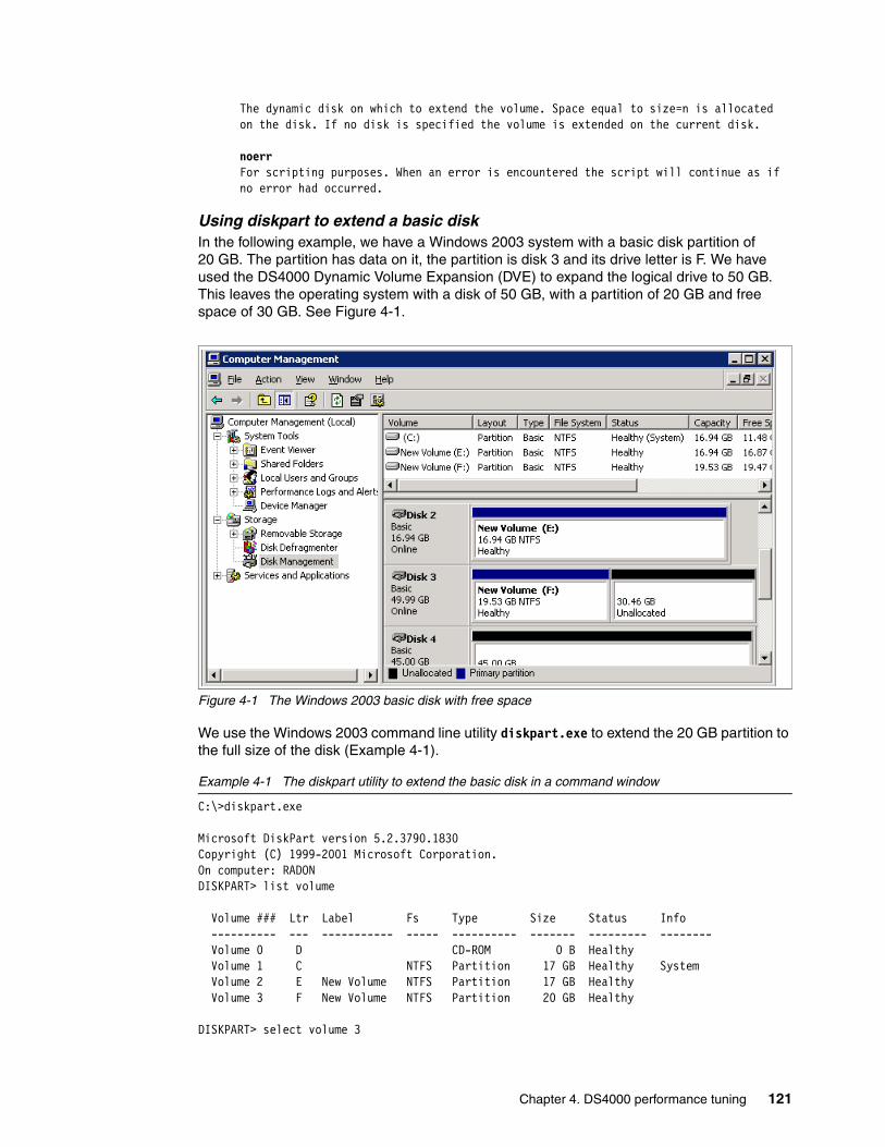
The dynamic disk on which to extend the volume. Space equal to size=n is allocated on the disk. If no disk is specified the volume is extended on the current disk.
noerrFor scripting purposes. When an error is encountered the script will continue as if no error had occurred.
Using diskpart to extend a basic diskIn the following example, we have a Windows 2003 system with a basic disk partition of 20 GB. The partition has data on it, the partition is disk 3 and its drive letter is F. We have used the DS4000 Dynamic Volume Expansion (DVE) to expand the logical drive to 50 GB. This leaves the operating system with a disk of 50 GB, with a partition of 20 GB and free space of 30 GB. See Figure 4-1.
Figure 4-1 The Windows 2003 basic disk with free space
We use the Windows 2003 command line utility diskpart.exe to extend the 20 GB partition to the full size of the disk (Example 4-1).
Example 4-1 The diskpart utility to extend the basic disk in a command window
C:\>diskpart.exe
Microsoft DiskPart version 5.2.3790.1830Copyright (C) 1999-2001 Microsoft Corporation.On computer: RADONDISKPART> list volume
Volume ### Ltr Label Fs Type Size Status Info ---------- --- ----------- ----- ---------- ------- --------- -------- Volume 0 D CD-ROM 0 B Healthy Volume 1 C NTFS Partition 17 GB Healthy System Volume 2 E New Volume NTFS Partition 17 GB Healthy Volume 3 F New Volume NTFS Partition 20 GB Healthy
DISKPART> select volume 3
Chapter 4. DS4000 performance tuning 121
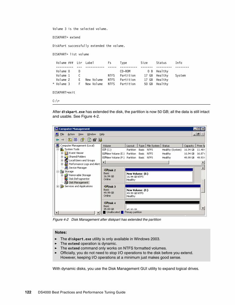
Volume 3 is the selected volume.
DISKPART> extend
DiskPart successfully extended the volume.
DISKPART> list volume
Volume ### Ltr Label Fs Type Size Status Info ---------- --- ----------- ----- ---------- ------- --------- -------- Volume 0 D CD-ROM 0 B Healthy Volume 1 C NTFS Partition 17 GB Healthy System Volume 2 E New Volume NTFS Partition 17 GB Healthy* Volume 3 F New Volume NTFS Partition 50 GB Healthy
DISKPART>exit
C:\>
After diskpart.exe has extended the disk, the partition is now 50 GB; all the data is still intact and usable. See Figure 4-2.
Figure 4-2 Disk Management after diskpart has extended the partition
With dynamic disks, you use the Disk Management GUI utility to expand logical drives.
Notes:
� The diskpart.exe utility is only available in Windows 2003.� The extend operation is dynamic.� The extend command only works on NTFS formatted volumes.� Officially, you do not need to stop I/O operations to the disk before you extend.
However, keeping I/O operations at a minimum just makes good sense.
122 DS4000 Best Practices and Performance Tuning Guide
Dynamic disksDynamic disks were first introduced with Windows 2000 and provide some features that basic disks do not. These features are the ability to create volumes that span multiple disks (spanned and striped volumes), and the ability to create software based fault tolerant volumes (mirrored and RAID-5 volumes).
Dynamic disks can use the Master Boot Record (MBR) or GUID partition table (GPT) partitioning scheme; this depends on the version of operating system and hardware. The x86 platform uses MBR and the itanium based 64 bit versions use GPT or MBR.
All volumes on dynamic disks are known as dynamic volumes. There are five types of dynamic volumes that are currently supported:
� Simple Volume: A simple volume is a volume created on a single dynamic disk.
� Spanned Volume: Spanned volumes combine areas of unallocated space from multiple disks into one logical volume. The areas of unallocated space can be different sizes. Spanned volumes require two disks, and you can use up to 32 disks. If one of the disks containing a spanned volume fails, the entire volume fails, and all data on the spanned volume becomes inaccessible.
� Striped Volume: Striped volumes improve disk I/O performance by distributing I/O requests across multiple disks. Striped volumes are composed of stripes of data of equal size written across each disk in the volume. They are created from equally sized, unallocated areas on two or more disks. The size of each stripe is 64 KB and cannot be changed.
Striped volumes cannot be extended or mirrored and do not offer fault tolerance. If one of the disks containing a striped volume fails, the entire volume fails, and all data on the striped volume becomes inaccessible. The reliability for the striped volume is only as good as the least reliable disk in the set.
� Mirrored Disk: A mirrored volume is a software level fault tolerant volume that provides a copy of a volume on another disk. Mirrored volumes provide data redundancy by duplicating the information contained on the volume. Each disk in the mirror is always located on a different disk. If one of the disks fails, the data on the failed disk becomes unavailable, but the system continues to operate by using the available disk.
� RAID 5 Volume: A software RAID 5 volume is a fault tolerant volume that stripes data and parity across three or more disks. Parity is a calculated value that is used to reconstruct data if one disk fails. When a disk fails, the server continues to operate by recreating the data that was on the failed disk from the remaining data and parity. This is software level RAID and is not to be confused with hardware level RAID, this has a performance impact to the operating system. We do not recommend using this volume type with a DS4000 Storage Server logical drive(s) included in it.
Dynamic disks offer greater flexibility for volume management because they use a database to track information about dynamic volumes on the disk, they also store information about other dynamic disks in the computer. Because each dynamic disk in a computer stores a replica of the dynamic disk database, you can repair a corrupted database on one dynamic disk by using the database from another dynamic disk in the computer.
The location of the database is determined by the partition style of the disk:
� On MBR disks, the database is contained in the last 1 megabyte of the disk.
� On GPT disks, the database is contained in a 1-MB reserved (hidden) partition known as the Logical Disk Manager (LDM) Metadata partition.
Chapter 4. DS4000 performance tuning 123
All online dynamic disks in a computer must be members of the same disk group. A disk group is a collection of dynamic disks. A computer can have only one dynamic disk group, this is called the primary disk group. Each disk in a disk group stores a replica of the dynamic disk database. A disk group usually has a name consisting of the computer name plus a suffix of Dg0.
Disk alignmentWith the DS4000 logical drives as with physical disks that maintain 64 sectors per track, the Windows operating system always creates the partition starting with the sixty-fourth sector. This results in the partition data layout being misaligned with the segment size layout of the DS4000 logical drives. To ensure that these are both aligned, you should use the diskpar.exe or diskpart.exe command, to define the start location of the partition.
The diskpar.exe command is part of the Microsoft Windows Server 2000 Resource Kit, it is for Windows 2000 and Windows 2003. The diskpar.exe functionality was put into diskpart.exe with Windows Server 2003 Service Pack 1.
Using this tool, you can set the starting offset in the Master Boot Record (MBR) by selecting 64, or 128 (sectors). By setting this value to 64, you will skip the first 32K before the start of first partition. If you set this value to 128, you will skip the first full 64K segment (where the MBR resides) before the start of the partition. The setting that you define depends on the allocation unit size of the formatted volume.
Doing so ensures track alignment and improves the performance. Other values can be defined, but these two offer the best chance to start out with the best alignment values. At a bare minimum, you should ensure that you aligned to at least a 4K boundary. Failure to do so may cause a single I/O operation to require the DS4000 to perform multiple IO operations on its internal processing, causing extra work for a small host IO, and resulting in performance degradation.
For more information, please use the following Web site:
http://www.microsoft.com/technet/prodtechnol/exchange/guides/StoragePerformance/0e24eb22-fbd5-4536-9cb4-2bd8e98806e7.mspx.
In Example 4-2, we align Disk 4 to the 128th sector and format it with 64K allocation unit size.
Important: The use of diskpart is a data destructive process. The diskpart utility is used to create partitions with the proper alignment. When used against a disk that contains data, all the data and the partitions on that disk must be wiped out, before the partition can be recreated with the storage track boundary alignment. Therefore, if the disk on which you will run diskpart contains data, you should back up the disk before performing the following procedure.
Note: Use diskpar.exe from the Microsoft Windows 2000 Resource Kit to create the partition with the disk aligned, for Windows 2000 and Windows 2003.
In Microsoft Windows 2003, the functionality of diskpar.exe was added to the diskpart.exe utility with Service Pack 1.
124 DS4000 Best Practices and Performance Tuning Guide

Example 4-2 Using diskpart in Windows 2003 Service Pack 1 to align the disks
From the command line run the following command:
diskpart.exe
DISKPART> select disk 4Disk 4 is now the selected disk.DISKPART> create partition primary align=128DiskPart succeeded in creating the specified partition.
Exit diskpart utility and start the Disk Management snap-in.Select the disk 4Select formatAssign volume labelLeave file system as NTFSChange Allocation unit size from default to 64K.Click Ok.
In Example 4-3, we align Disk 4 to the 64th sector and format it with the default 4K allocation unit size.
Example 4-3 Using diskpart in Windows 2003 Service Pack 1 to align the disks
From the command line run the following command:
diskpart.exe
DISKPART> select disk 4Disk 4 is now the selected disk.DISKPART> create partition primary align=64DiskPart succeeded in creating the specified partition.
Exit diskpart utility and start the Disk Management snap-in.Select the disk 4Select formatAssign volume labelLeave file system as NTFSLeave Allocation unit size at default (4K).Click Ok.
Allocation unit sizeAn allocation unit (or cluster) is the smallest amount of disk space that can be allocated to hold a file. All file systems used by Windows 2000, and Windows 2003 organize hard disks based on an allocation unit size, which is determined by the number of sectors that the cluster contains. For example, on a disk that uses 512-byte sectors, a 512-byte cluster contains one sector, whereas a 4KB cluster contains eight sectors. See Table 4-1.
Table 4-1 Default cluster sizes for volumes
Volume Size Default NTFS allocation unit size
7 Mb to 512Mb 512 bytes
513 Mb to 1024 Mb 1 Kb
1025 Mb to 2 Gb 2 Kb
2 Gb to 2 Tb 4 Kb
Chapter 4. DS4000 performance tuning 125
In the Disk Management snap-in, you can specify an allocation unit size of up to 64 KB when you format a volume. If you use the format command to format a volume, but do not specify a an allocation unit size by using the /a:size parameter, the default values shown in Table 4-1 are used. If you want to change the cluster size after the volume is formatted, you must reformat the volume. This must be done with care as all data is lost when a volume is formatted. The available allocation unit sizes when formatting are 512 bytes, 1K, 2K, 4K, 8K, 16K, 32K and 64K.
For more information about formatting an NTFS disk, see the Windows 2000 and Windows 2003 documentation.
4.4 Application considerationsWhen gathering data for planning from the application side, it is again important to first consider the workload type for the application.
If multiple applications or workload types will be sharing the system, you need to know the type of workloads each have; and if mixed (transaction and throughput based) which will be the most critical. Many environments have a mix of transaction and throughput workloads; with generally the transaction performance being considered the most critical.
However, in dedicated environments (for example, a TSM backup server with a dedicated DS4000 Storage Server attached), the streaming high throughput workload of the backup itself would be the critical part of the operation; and the backup database, though a transaction centered workload, is the less critical piece.
Transaction environmentsApplications that use high transaction workloads are OnLine Transaction Processing (OLTP), mostly databases, mail servers, Web servers, and file servers.
If you have a database, you would tune the server type parameters as well as the database’s logical drives to meet the needs of the database application. If the host server has a secondary role of performing nightly backups for the business, you would need another set of logical drives that are tuned for high throughput for the best backup performance you can get within the limitations of the mixed storage server’s parameters.
So, what are the traits of a transaction based application? In the following sections we explain this in more detail.
Important: The allocation unit size is set during a format of a volume. This procedure is data destructive, so if the volume on which you will run a format contains data, you should back up the volume before performing the format procedure.
Restriction: In Windows 2000 and Windows 2003, setting an allocation unit size larger than 4K will disable file or folder compression on that partition.
In Windows 2000, the disk defragmenter ceased to function with an allocation size greater than 4K. In Windows 2003, the disk defragmenter functions correctly.
In your environment, always test to ensure that all the functionality remains after any changes.
126 DS4000 Best Practices and Performance Tuning Guide

As mentioned earlier, you can expect to see a high number of transactions and a fairly small block size. Different databases use different IO sizes for their logs (see examples below), these vary from vendor to vendor. In all cases the logs are generally high write workloads. For tablespaces most databases use between a 4KB and 16KB blocksize. In some applications larger chunks (like 64KB) will be moved to host application cache memory for processing. Understanding how your application is going to handle its IO is critical to laying out the data properly on the storage server.
In many cases the tablespace is generally a large file made up of small blocks of data records. The records are normally accessed using small IOs of a random nature, which can result in about a 50% cache miss ratio.
For this reason, and to not waste space with unused data, plan for the DS4000 to read and write data into cache in small chunks. Avoid also doing any cache read-ahead with the logical drives, due to the random nature of the IOs (Web servers and file servers frequently use 8KB as well, and would generally follow these rules as well).
Another point to consider is whether the typical IO is read, or write? In most “OnLine Transaction Processing (OLTP) environments this is generally seen to be a mix of about 70% reads, and 30% writes. However, the transaction logs of a database application have a much high write ratio, and as such perform better in a different RAID array. This reason also adds to the need to place the logs on a separate logical drive which for best performance should be located on a different array that is defined to better support the heavy write need. Mail servers also frequently have a higher write ratio than read. Use the RAID array configuration for your specific usage model. This is covered in detail in “RAID array types” on page 136.
Throughput environmentsWith throughput workloads you have fewer transactions, but much greater size IOs. IO sizes of 128K or greater are normally seen; and these IOs are generally of a sequential nature. Applications that typify this type of workload are imaging, video servers, seismic processing, high performance computing (HPC) and backup servers.
With large size IO, it is better to use large cache blocks to be able to write larger chunks into cache with each operation. Ensure the storage server is configured for this type of IO load. This is covered in detail in “Cache blocksize selection” on page 134.
These environments best work when defining the IO layout to be equal to or an even multiple of the storage servers stripe width. There are advantages with writes in the RAID 5 configurations that make setting the IO size to equal that of the “full stripe” performant. Generally, the desire here is to make the sequential IOs take as few back-end IOs as possible, and to get maximum throughput from them. So, care should be taken when deciding how the logical drive will be defined. We discuss these choices in greater detail in “Logical drive segments” on page 139.
4.4.1 Application examplesFor general suggestions and tips to consider when implementing certain applications with the DS4000 Storage Servers, refer to Chapter 5, “DS4000 tuning with typical application examples” on page 143.
Best Practice: Database tablespaces, journals and logs should never be co-located on the same logical drive or RAID array. See further recommendations in 4.5, “DS4000 Storage Server considerations” on page 128 for RAID types to use.
Chapter 4. DS4000 performance tuning 127

4.5 DS4000 Storage Server considerations In this section we look at the specific details surrounding the DS4000 Storage Server itself when considering performance planning and configuring. Topics covered in this section are:
� Which model fits best� Storage server processes� Storage server modification functions� Storage server parameters� Disk drive types� Arrays and logical drives� Additional NVSRAM parameters of concern
4.5.1 Which model fits bestWhen planning for a DS4000 Storage Server, the first thing to consider is the choice of an appropriate model for your environment and the type of workload it will handle.
You want to be sure, if your workload is going to require a high number of disks, that the system chosen will support them, and the IO workload they will be processing. If the workload you have requires a high storage server bandwidth, then you want your storage server to have a data bus bandwidth in line with the throughput and workload needs. See Figure 4-3, Figure 4-4, Figure 4-5, and Figure 4-6 for details on the DS4000 Storage Server family.
Figure 4-3 DS4000 Storage Server Family Comparison
DS4000 Specification Comparison
512 MB
Integrated
Intel xScale
600MHz
Up to 800MB/s
4 FC-SW
4 FC-SW
2Gp/s SFP
DS4300 Dual
512 MB2 GB2 GB2 GB16 GBCache memory
Integrated
Intel xScale600MHz
Up to 800MB/s
4 FC-AL
4 FC-SW
2 Gbps FC
DS4100
Intel xScale600MHz
Up to 800MB/s
Intel Celeron566MHz
Up to 792MB/s
Intel Pentium III 850 MHz
Up to 1.6GB/s
Intel Xeon 2.4Ghz
Up to 2GB/s
Processor
Data Bus Bandwidth
Integrated
4 FC-AL
4 FC-SW
2 Gbps FC
DS4300 Turbo
ASICASICASICXOR technology
8 FC-AL8 FC-AL16 FC-ALDirect attachments (max)
4 FC-SW4 FC-SW8 FC-SWSAN attachments (max)
4 Gbps FC
DS4800
2 Gbps FC2 Gbps FCHost Interfaces
DS4500 DS4400*
* Discontinued as of June 2005
128 DS4000 Best Practices and Performance Tuning Guide
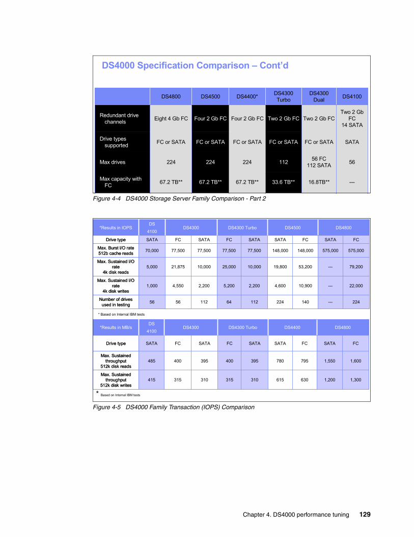
Figure 4-4 DS4000 Storage Server Family Comparison - Part 2
Figure 4-5 DS4000 Family Transaction (IOPS) Comparison
DS4000 Specification Comparison – Cont’d
16.8TB**
56 FC 112 SATA
FC or SATA
Two 2 Gb FC
DS4300 Dual
56112224224224Max drives
SATAFC or SATAFC or SATAFC or SATAFC or SATADrive types supported
---
Two 2 Gb FC
14 SATA
DS4100
33.6 TB**
Two 2 Gb FC
DS4300 Turbo
67.2 TB**67.2 TB**67.2 TB**Max capacity with FC
Eight 4 Gb FC
DS4800
Four 2 Gb FCFour 2 Gb FCRedundant drive channels
DS4500 DS4400*
224
4,600
19,800
148,000
SATA
112
2,200
10,000
77,500
SATA
64
5,200
25,000
77,500
FC
DS4300 Turbo
575,000575,000148,00077,50077,50070,000Max. Burst I/O rate 512b cache reads
56
1,000
5,000
SATA
DS
4100
79,200---53,20010,00021,875Max. Sustained I/O
rate4k disk reads
140
10,900
FC
DS4500
224---112 56 Number of drives used in testing
2,200
SATA
22,000---4,550Max. Sustained I/O
rate 4k disk writes
FCSATAFCDrive type
DS4300 DS4800*Results in IOPS
630
795
FC
310
395
SATA
315
400
FC
DS4300 Turbo
415
485
SATA
DS
4100
1,6001,550780395400Max. Sustained
throughput512k disk reads
615
SATA
DS4400
310
SATA
1,3001,200315Max. Sustained
throughput 512k disk writes
FCSATAFCDrive type
DS4300 DS4800*Results in MB/s
630
795
FC
310
395
SATA
315
400
FC
DS4300 Turbo
415
485
SATA
DS
4100
1,6001,550780395400Max. Sustained
throughput512k disk reads
615
SATA
DS4400
310
SATA
1,3001,200315Max. Sustained
throughput 512k disk writes
FCSATAFCDrive type
DS4300 DS4800*Results in MB/s
* Based on Internal IBM tests
* Based on Internal IBM tests
Chapter 4. DS4000 performance tuning 129
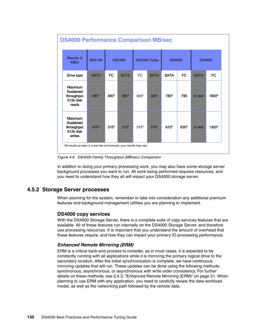
Figure 4-6 DS4000 Family Throughput (MB/sec) Comparison
In addition to doing your primary processing work, you may also have some storage server background processes you want to run. All work being performed requires resources, and you need to understand how they all will impact your DS4000 storage server.
4.5.2 Storage Server processesWhen planning for the system, remember to take into consideration any additional premium features and background management utilities you are planning to implement.
DS4000 copy servicesWith the DS4000 Storage Server, there is a complete suite of copy services features that are available. All of these features run internally on the DS4000 Storage Server, and therefore use processing resources. It is important that you understand the amount of overhead that these features require, and how they can impact your primary IO processing performance.
Enhanced Remote Mirroring (ERM)ERM is a critical back-end process to consider, as in most cases, it is expected to be constantly running with all applications while it is mirroring the primary logical drive to the secondary location. After the initial synchronization is complete, we have continuous mirroring updates that will run. These updates can be done using the following methods: synchronous, asynchronous, or asynchronous with write order consistency. For further details on these methods, see 2.4.3, “Enhanced Remote Mirroring (ERM)” on page 51. When planning to use ERM with any application, you need to carefully review the data workload model, as well as the networking path followed by the remote data.
DS4000 Performance Comparison MB/sec
630*
795
FC
310*
395*
SATA
315*
400*
FC
DS4300 Turbo
415*
485*
SATA
DS4100
1600*In test780*395*400*
Maximum Sustained throughput512k disk
reads
615*
SATA
DS4500
310*
SATA
1300*In test315*
Maximum Sustained throughput 512k disk
writes
FCSATAFCDrive type
DS4300 DS4800Results in MB/s
630*
795
FC
310*
395*
SATA
315*
400*
FC
DS4300 Turbo
415*
485*
SATA
DS4100
1600*In test780*395*400*
Maximum Sustained throughput512k disk
reads
615*
SATA
DS4500
310*
SATA
1300*In test315*
Maximum Sustained throughput 512k disk
writes
FCSATAFCDrive type
DS4300 DS4800Results in MB/s
*All results as seen in a test lab environment; your results may vary.
130 DS4000 Best Practices and Performance Tuning Guide

With the level of overhead ERM can have, consider the following system recommendations:
� DS4800 and DS4500 are the best choice when ERM is a strategic part of your storage plan.
� DS4300T and DS4400 are acceptable when the need for limited concurrent ERM pairs are needed for processing.
� DS4100 and DS4300 are acceptable for small (1 or 2) ERM pairs for processing; but still will highly impact the primary’s side processing.
In all cases we have the initial synchronization overhead we need to consider. When a storage subsystem logical drive is a primary logical drive and a full synchronization is necessary, the controller owner performs the full synchronization in the background while processing local I/O writes to the primary logical drive and associated remote writes to the secondary logical drive. Because the full synchronization diverts controller processing resources from I/O activity, it will impact performance on the host application. The synchronization priority allows you to define how much processing time is allocated for synchronization activities relative to other system work so that you can maintain accepted performance.
The synchronization priority rates are lowest, low, medium, high, and highest.
The following guidelines roughly approximate the differences between the five priorities. Logical drive size and host I/O rate loads affect the synchronization time comparisons:
� A full synchronization at the lowest synchronization priority rate takes approximately eight times as long as a full synchronization at the highest synchronization priority rate.
� A full synchronization at the low synchronization priority rate takes approximately six times as long as a full synchronization at the highest synchronization priority rate.
� A full synchronization at the medium synchronization priority rate takes approximately three and a half times as long as a full synchronization at the highest synchronization priority rate.
� A full synchronization at the high synchronization priority rate takes approximately twice as long as a full synchronization at the highest synchronization priority rate.
The synchronization progress bar at the bottom of the Mirroring tab of the logical drive Properties dialog box displays the progress of a full synchronization.
VolumeCopy functionWith VolumeCopy, several factors contribute to system performance, including I/O activity, logical drive RAID level, logical drive configuration (number of drives in the array or cache parameters), and logical drive type. For instance, copying from a FlashCopy logical drives might take more time to copy than standard logical drives. A major point to consider is whether you want to be able to perform the function while the host server applications are functioning, or during an outage. If the outage is not desired, using the FlashCopy volume as the source will allow you to perform your VolumeCopy in the background while normal processing continues. Like the ERM functions, VolumeCopy does have a background process penalty which you need to decide how much you want it to affect your front-end host. With the FlashCopy image you can use lower priority and leave it run for more extended time. This will make your VolumeCopy creation take longer but decrease the performance hit. As this value can be adjusted dynamically you can increase it when host processing is slower.
Note: The lowest priority rate favors system performance, but the full synchronization takes longer. The highest priority rate favors full synchronization, but system performance can be compromised.
Chapter 4. DS4000 performance tuning 131
You can select the copy priority when you are creating a new logical drive copy, or you can change it later using the Copy Manager. The copy priority rates are lowest, low, medium, high, and highest.
FlashCopy functionIf you no longer need a FlashCopy logical drive, you should disable it. As long as a FlashCopy logical drive is enabled, your storage subsystem performance is impacted by the copy-on-write activity to the associated FlashCopy repository logical drive. When you disable a FlashCopy logical drive, the copy-on-write activity stops.
If you disable the FlashCopy logical drive instead of deleting it, you can retain it and its associated repository. Then, when you need to create a different FlashCopy of the same base logical drive, you can use the re-create option to reuse a disabled FlashCopy. This takes less time.
4.5.3 Storage Server modification functionsThe DS4000 Storage Servers have many modification functions that can be used to change, tuning, clean, or redefine the storage dynamically. Some of these functions are useful to help improve the performance as well. However, all of these will have an impact on the performance of the storage server and its host IO processing. All of these functions use the modification priority rates to determine their process priority. Values to chose from are lowest, low, medium, high, and highest.
In the following sections we describe the use of each of these functions and their impact on performance.
Media ScanMedia Scan is a background check performed on all logical drives in the DS4000 storage server when selected to ensure that the blocks of data are good. This is accomplished by reading the logical drives one data stripe at a time into cache, and if successful it moves on to the next stripe. If a bad block is encountered, it will retry three times to read the block, and then go into its recovery process to rebuild the data block.
Media scan is configured to run on selected logical drives; and has a parameter for defining the maximum amount of time allowed to complete its run through all the logical drives selected. If the media scan process sees it is reaching its maximum run time and calculates that it is not going to complete in the time remaining, it will increase its priority and can impact host processing. Generally, it has been found that media scan scheduled with a “30 day” completion schedule, is able to complete if controller utilization does not exceed 95%. Shorter schedules would require lower utilization rates to avoid impact.
Note: The lowest priority rate supports I/O activity, but the logical drive copy takes longer. The highest priority rate supports the logical drive copy, but I/O activity can be affected.
Note: The lowest priority rate favors system performance, but the modification operation takes longer. The highest priority rate favors the modification operation, but system performance can be compromised.
Best Practice: Setting media scan to 30 days has been found to be a good general all around value to aid in keeping media clear and server background process load at an acceptable level.
132 DS4000 Best Practices and Performance Tuning Guide

Defragmenting an arrayA fragmented array can result from logical drive deletion resulting in free space node; and/or not using all available free capacity in a free capacity node during a logical drive creation.
Because creation of new logical drives cannot spread across several free space nodes, the logical drive size is limited to the greatest amount of a free space node available, even if there is more free space in the array. The array needs to be defragmented first to consolidate all free space nodes to one free capacity node for the array. Then, a new logical drive can use the whole available free space.
Use the defragment option to consolidate all free capacity on a selected array. The defragmentation runs concurrently with normal I/O; it impacts performance, because the data of the logical drives must be moved within the array. Depending on the array configuration, this process continues to run for a long period of time.
The defragmentation done on the DS4000 Storage Server only applies to the free space nodes on the array. It is not connected to a defragmentation of the file system used by the host operating systems in any way.
CopybackCopyback refers to the copying of data from a hot-spare drive (used as a standby in case of possible drive failure) to a replacement drive. When you physically replace the failed drive, a copyback operation automatically occurs from the hot-spare drive to the replacement drive.
InitializationThis is the deletion of all data on a drive, logical drive, or array. In previous versions of the storage management software, this was called format.
Dynamic Segment Sizing (DSS)Dynamic Segment Sizing (DSS) describes a modification operation where the segment size for a select logical drive is changed to increase or decrease the number of data blocks that the segment size contains. A segment is the amount of data that the controller writes on a single drive in a logical drive before writing data on the next drive.
Dynamic Reconstruction Rate (DRR)Dynamic Reconstruction Rate (DRR) is a modification operation where data and parity within an array are used to regenerate the data to a replacement drive or a hot spare drive. Only data on a RAID-1, -3, or -5 logical drive can be reconstructed.
Dynamic RAID Level Migration (DRM)Dynamic RAID Level Migration (DRM) describes a modification operation used to change the RAID level on a selected array. The RAID level selected determines the level of performance and parity of an array.
Dynamic Capacity Expansion (DCE)Dynamic Capacity Expansion (DCE) describes a modification operation used to increase the available free capacity on an array. The increase in capacity is achieved by selecting unassigned drives to be added to the array. After the capacity expansion is completed, additional free capacity is available on the array for the creation of other logical drives. The additional free capacity can then be used to perform a Dynamic logical drive Expansion (DVE) on a standard or FlashCopy repository logical drive.
Important: Once this procedure is started, it cannot be stopped; and no configuration changes can be performed on the array while it is running.
Chapter 4. DS4000 performance tuning 133
Dynamic logical drive Expansion (DVE)Dynamic logical drive Expansion (DVE) is a modification operation used to increase the capacity of a standard logical drive or a FlashCopy repository logical drive. The increase in capacity is achieved by using the free capacity available on the array of the standard or FlashCopy repository logical drive.
4.5.4 Storage Server parametersSettings on the DS4000 Storage Server are divided into two groups. The storage server wide parameters which affect all workloads that reside on the storage. And settings which are specific to the array or logical drive where the data resides.
Cache blocksize selectionOn the DS4000 Storage Server the cache blocksize is a variable value that can be set to 4K or 16K. The main goal with setting this value is to not waste space. This is a storage server wide parameter, and when set, it is the value to be used by all cache operations.
For example, if the IO of greatest interest is that from your database operations during the day rather than your weekly backups, you would want to tune this value to handle the high transactions best. Knowing that the higher transactions will have smaller IO size, using the 4K setting is generally best for transaction intense environments.
In a throughput intense environment as we discussed earlier, you would want to get as much data into cache as possible. In this environment it is generally best to use the 16K blocksize for the cache.
In mixed workload environments, you must decide which workload type is most critical and set the system wide settings to best handle your business needs.
Cache flush control settingsIn addition to the cache blocksize the DS4000 Storage Server also has a cache control which determines the amount of data that can be held in write cache. With the cache flush settings you can determine what level of write cache usage can be reached before the server will start to flush the data to disks, and at what level the flushing will stop.
By default, these parameters are set to the value of “80” for each. This means that the server will wait until 80% of the write cache is used before it will flush the data to disk. In a fairly active write environment this value could be far too high.You can adjust these settings up and down until you find the value that best suites your environment. If the values are different from each other then back-end drive inactive time increases, and you have surging with peaks and valleys occurring instead of a steady usage of back-end disks.
Best Practice: Set the cache blocksize to 4K for the DS4000 system normally for transaction intense environments.
Best Practice: Set the cache blocksize to 16K for the DS4000 system normally for throughput intense environments
Tip: Throughput operations though impacted by smaller cache blocksize can still perform reasonable if all other efforts have been accounted for. Transaction based operations are normally the higher concern, and therefore should be the focus for setting the server wide values if applicable.
134 DS4000 Best Practices and Performance Tuning Guide

You can also vary the maximum amount of time the write data can remain in cache prior to being forced out, and written to disks. This value by default is set to ten seconds but can be changed by using the Storage Manager command line interface command below:
‘set logical Drive [LUN] cacheflushModifier=[new_value];’
4.5.5 Disk drive typesWith the DS4000 Storage server there are many different types of disk drives that are available to you to chose from. There are both the Fibre Channel, as well as the Serial ATA (SATA) drives. The following is a table of the drives types that are available. We recommend using the 15K RPM models for the highest performance. The 10K RPM drives run a close second; while the 7200 RPM drives are the slowest. SATA drives can be used in lower transaction intense environments where maximum performance needs are less important, and high storage capacity, or price are main concerns. SATA drives do provide good throughput performance and can be a very good choice for these environments.
Table 4-2 Comparison between Fibre Channel and SATA
Drive sizes available for selecting from are 36 GB, 73 GB, 146 GB, and a 300 GB/10K RPM on the Fibre Channel side; and a 250 GB, and new 400 GB SATA drive. When selecting a drive size for a performant DS4000 environment you must consider how much data will reside on each disk. If large drives are used to store a heavy transaction environment on fewer drives, then the performance will be impacted. If using large size drives and high numbers of them, then how the drive will be used becomes another variable. Some cases, where you prefer RAID 1 to RAID 5 a larger drive may be a reasonable cost compromise; but only testing with your real data and environment can show for sure.
The current DS4000 Storage Servers support a drive side IO queue depth of “16” for the Fibre Channel disks. The SATA drives support only single IOs. In the early DS4000 storage servers only one IO was supported per Fibre Channel disk as well. The new queueing capability was introduced at firmware level 5.4.x.
Best Practice: Start with “Start/Stop flush settings of 50/50, and adjust from there. Always keep them equal to each other.
Fibre Channel SATA SATA difference
Spin Speed 10K and 15K 7.2K
Command Queuing Yes16 Max
No1 Max
Single Disk IO Ratea
(# of 512 bytes IOPS)
a. Note that the IOPS and bandwidth figures are from disk manufacturer test in ideal lab conditions. In practice you will see lower numbers, but the ratio between SATA and FC disks still applies
280 & 340 88 .31 & .25
Read Bandwidth (MB/s)
69 & 76 60 .86 & .78
Write Bandwidth (MB/s)
68 & 71 30 .44
Best Practice: For transaction intense workload, we recommend using 36 GB or 73GB drives for the best performance.
Chapter 4. DS4000 performance tuning 135
4.5.6 Arrays and logical drivesWhen setting up the DS4000 Storage Server the configuration of the arrays and logical drives is most likely the single most critical piece in your planning. Understanding how your workload will use the storage is crucial to the success of your performance, and your planning of the arrays and logical drives to be used.
RAID array typesWhen configuring a DS4000 Storage Server for the transaction intense environment you need to consider also whether it will be a read or write intensive workload. As mentioned earlier, in a database environment we actually have two separate environments with the tablespace, and the journals and logs. As the tablespace is normally high reads and low writes, and the journals and logs are high writes with low reads. This environment is best served by two different RAID types.
RAID 0, which is striping, without mirroring or parity protection, is generally the best choice for almost all environments for max performance; however, there is no protection built into RAID 0 at all, and a drive failure requires a complete restore. For protection it is necessary to look toward one of the other RAID types.
On the DS4000 Storage server RAID 1 is disk mirroring for the first pair of disks, and for larger arrays of four or more, disks mirroring and striping (RAID10 model) is used. This RAID type is a very good performer for high random write environments. It outperforms RAID 5 due to additional reads that RAID 5 requires in performing it’s parity check when doing the write operations. With RAID1 there are two writes performed per operation; where as with RAID 5 there are two reads and two writes required for the same operation, totaling four IOs.
A common use for RAID 1 is for the mailserver environment where random writes can frequently out-weigh the reads.
Some people feel strongly about database journals and logs also belonging on RAID 1 as well. This is something that should be reviewed for your specific environment. As these processes are generally sequential write intensive IOs, you may find that RAID 5 with proper layout for the host IO size can give you the same if not better performance with “full stripe write” planning.
RAID 5, however, is better than RAID 1 in high random read environments. This is due to there being a greater number of disks and the ability to have less seeking. This can make RAID 5 superior to RAID 1 when handling the OLTP type workload with the higher read and lower writes, even with increased table sizes.
In the sequential high throughput environment RAID 5 can exactly perform excellent, as it can be configured to perform just one additional parity write when using “full stripe writes” (or “full stride writes”) to perform a large write IO, as compared to the two writes per data drive (self, and its mirror) that are needed by RAID 1. This model is a definite advantage for RAID 5.
So with these differences, you can either place the database journals and logs on a RAID 1 or a RAID 5, depending on how sequential and well fit your data is. Testing of both types of arrays for your best performance is recommended.
Tip: There are no guaranteed choices as to which type of RAID to use; as this is very much dependent on the workload read and write activity. A good general guide may be to consider using RAID 1 if random writes exceed about 25%, with a peak sustained IO rate exceeds 50% of the storage server’s capacity.
136 DS4000 Best Practices and Performance Tuning Guide
With the amount of variance that can exist with each customer environment, it is strongly recommended that you test your specific case for best performance; and decide which layout to use. With the write cache capability, in many cases RAID 5 write penalties are not noticed, as long as the back-end disk configuration is capable of keeping up with the front-end IO load so processing is not being slowed. This again points to ensuring that proper spreading is done for best performance.
Number of disks per arrayIn the transaction intense environment it is more important to ensure that there are enough disk drives configured to perform the IOs demanded by the host application, than to focus on the amount of possible storage space on the storage server.
With the DS4000 you can purchase 36 GB, 73 GB, 146 GB, or 300 GB Fibre Channel disk drives. Obviously, with the larger drives you can store more data using fewer drives.
Transaction intensive workloadIn a transaction intense environment, you want to have higher drive numbers involved. This can be done by creating larger arrays with more disks of a smaller size. The DS4000 can have a maximum of 30 drives per array/logical drive (although operating system limitations on a maximum logical drive capacity may restrict the usefulness of this capability).
For large size databases consider using the host volume management software to build the database volume to be used for the application. Build the volume across sets of logical drives laid out per the RAID type discussion above. In using multiple arrays you will also be able to increase the controllers which are involved in handling the load therefore getting full use of the storage servers resources.
For example: If needing to build a database that is 1 TB in size, you can use five 300 GB drives in a 4 + 1parity RAID 5 single array/logical drive; or you could create two RAID 5 arrays of 8 + 1parity using 73 GB drives, giving two 584 GB logical drives on which to build the 1 TB database. In most cases the second method for large databases will work best, as it brings twelve more disks into play for handling the host side high transaction workload.
Large throughput workloadIn the large throughput environment, it typically does not take high numbers of disks to reach the maximum sustained throughput. Considering that this type of workload is usually made of sequential IO, which reduces disk latency, in most cases about 20 to 28 drives are enough to reach the maximum throughput.
This does, however, require that the drives be spread evenly across the DS4000 storage server to best utilize the server bandwidth. The DS4000 is optimized in its firmware to give increased throughput when the load is spread across all parts. Here, bringing all the DS4000 storage server resources into play is extremely important. Keeping the drives, channels, and bus busy with high data throughput is the winning answer. This is also a perfect model for
Best Practice: The differences described above outline the major reasons for our recommendation to keep the journals and logs on different arrays than the tablespaces for database applications.
Best Practice: For high transactions environment, logical drives should be built on arrays with highest even number of data drives supported (+ 1parity) when using RAID 5; and highest number of supported and available drives / 2 when using RAID 10.
Chapter 4. DS4000 performance tuning 137

using the high capacity drives, as we are looking to push a large volume of data and it will likely be large blocks of sequential reads and writes.
Consider building smaller arrays with single logical drives for higher combined throughput.
An example configuration for this environment would be to have a single logical drive /array with 16+1 parity 300 GB disks doing all the transfers through one single path and controller; An alternative would be two 8 + 1parity defined to the two controllers using separate paths, doing two separate streams of heavy throughput in parallel and filling all the channels and resources at the same time. This keeps the whole server busy with a cost of one additional drive.
Further improvements may be gained by splitting the two 8 + 1parity into four 4 + 1parity arrays giving four streams, but addition of three drives would be needed. A main consideration here is to plan for the array data drive count to be a number such that the host IO blocksize can be evenly spread using one of the DS4000 segment size selections. This will enable the full stripe write capability discussed in the next section.
Array and logical drive creationAn array is the grouping of drives together in a specific RAID type format on which the logical unit (logical drive) will be built for presentation to the host(s). As described in 3.3.2, “Creating arrays and logical drives” on page 85, there are a number of ways to create an array on the DS4000 Storage Server using the Storage Manager Client.
For best layout and optimum performance, we recommend that you manually select the drives when defining arrays. Drives should be across expansions for protection, and is best for them to stagger the across the odd and even slots for balance across the drive channel loops. Frequently this is accomplished by selecting them in an orthogonal manner. However you plan them, try to focus on keeping the load spread evenly.
With the DS4800 Storage Server the layout recommendation is slightly different. With the small configuration, we recommend that you try to bring as many channels into play as you can. When large disk expansion configurations are installed, we recommend that arrays and logical drives be built across expansions that are on a redundant channel drive loop pair as described in “Enclosure loss protection planning” on page 36 and 3.3.2, “Creating arrays and logical drives” on page 85.
A logical drive is the portion of the array that is presented to the host from the storage server. A logical drive can be equal to the entire size of the array, or just a portion of the array. A logical drive will be striped across all the data disks in the array. Generally, we recommend that you try to keep the number of logical drives on a array to a low number. However, in some cases this is not possible, and then planning of how the logical drives are used becomes very important. You must remember that each logical drive will have its own IOs from its hosts queuing up against the drives that are in the same array. Multiple heavy transaction applications using the same array of disks can result in that array having poor performance for all its logical drives.
Best Practice: For high throughput, logical drives should be built on arrays with 4+1, or 8+1 drives in them when using RAID 5. Data drive number and segment size should equal Host IO blocksize for “full stripe write”. Use multiple logical drives on separate arrays for maximum throughput.
Best Practice: We recommend that you create a single logical drive for each array when possible.
138 DS4000 Best Practices and Performance Tuning Guide
When configuring multiple logical drives on an array, try to spread out their usage evenly to have a balanced workload on the disks making up the arrays. A major point to remember here is to try to keep all the disks busy. Also, you will want to tune the logical drive separately for their specific workload environments.
Logical drive segments The segment size is the maximum amount of data that is written or read from a disk per operation before the next disk in the array is used. As mentioned earlier, we recommend that for small host IOs, the segment size be as large or larger than the host IO size. This is to prevent the need to access a second drive for a single small host IO. In some storage servers having the segment size equal to the host IO size is recommended. This is not the case with the DS4000 servers.
There is no advantage in using smaller sizes with RAID 1; only in a few instances does this help with RAID 5 (which we discuss later). As the only amount of data written to cache is that which is to be written, for the IO, there is no cache penalty either. As mentioned earlier in the host sections aligning data on segment boundaries is very important to performance. With larger segment sizes, there are less occasions of having misaligned boundaries impacting your performance as more small IO boundaries reside within a single segment decreasing the chance of a host IO spanning multiple drives. This can be used to help eliminate the effect of poor layout of the host data on the disks due to boundary differences.
With high throughput workload, the focus is on moving high throughput in fewer IOs. This workload is generally sequential in nature.
These environments best work when we define the IO layout to be equal to or an even multiple of the logical drive stripe width. The total of all the segments for one pass of all the back-end data disks is a stripe. So, large segment sizes that can equal the IO size may be desired to accomplish the higher throughput you are looking for. For high read throughput, you want to have large segments (128K or higher) to get the most from each stripe. If the host IO is 512KB or larger, you would want to use at least a 256KB segment size.
When the workload is high writes, and we are using RAID 5, we can use a method known as full stripe (stride) write which may work well to improve your performance. With RAID 5 the parity is based on the value calculated for a stripe. So, when the IO being written is spread across the entire stripe width, no reads are required to calculate the parity; and the IO completes with fewer back-end IOs being required. This design may use a smaller segment size to align the host IO size with the size of the stripe width. This type of management requires that very few host IOs not equal a full stripe width.
The decrease in the overhead read operations is the advantage you are looking for. You must be very careful when implementing this type of layout to ensure that your data pattern does not change, and decrease its effectiveness. However, this layout may work well for you in a write intense environment. Due to the small size of segments, reads may suffer, so mixed IO environments may not fair well. This would be worth testing if your writes are high.
Best Practice: With the DS4000 Storage Server, we recommend that the segment size be 64KB to 128KB for most high transaction workloads.
Best Practice: In the throughput environment, you want the stripe size to be equal to, or an even multiple of, the host IO size.
Chapter 4. DS4000 performance tuning 139
Logical drive cache settingsNow, to help enhance the use of the system data cache, the DS4000 Storage Server has some very useful tuning parameters which help the specific logical drive in its defined environment. One such parameter is the cache read-ahead multiplier (see also 2.3.7, “Cache parameters” on page 45). This parameter is used to increase the number of segments that are read into cache to increase the amount of data that is readily available to present to the host for sequential IO requests. To avoid excess read IOs in the random small transaction intense environments you should disable the cache read-ahead multiplier for the logical drive by setting it to “0”.
In the throughput environment where you want more throughput faster, you should generally enable this parameter to deliver more than one segment to the cache at a time.
� With pre-6.1x.xx firmware code this value could be set by the user to what was believed to be the value needed. For this code base we recommend the start value to be set to “4”, and adjusted as needed from there. When enabled the controller will read ahead into cache the next 4 sequential segments for immediate use from cache.
� With 6.1x and later code this value can be set to either “0” to disable the read-ahead feature, or “any value other than 0” to enable it. The 6.1x or later code will analyze the data pattern and determine the best value of read-ahead for the specific logical drive; and then use that value to pull additional cached segments for follow-on IO requests to improve the performance. The number of segments read in advance are determined by the storage server using an algorithm of past IO patterns to the logical drive. With the newer code you cannot set a value for the logical drive to stay with.
For write IO in a transaction based environment you can enable write cache, and write cache mirroring for cache protection. This allows the write IOs to be acknowledged even before they are written to disks as the data is in cache, and backed up by the second mirror in the other controller’s cache. This improves write performance dramatically; this sequence is actually a set of two options doing both write caching, and mirroring to the second cache. If you are performing a process that can handle loss of data, and can be restarted, you may chose to disable the mirroring, and see very high write performance.
In most transaction intense environments where the data is a live OLTP update environment, this is not an option that can be chosen; however, in cases like table updates, where you are loading in new values, and can restart the load over, this can be a way of greatly reducing the load time; and therefore shortening your downtime window. As much as three times the performance can be gained with this action.
For write IO in the throughput sequential environment, these two parameters again come into play and can give you the same basic values. It should be noted that many sequential processes are more likely to be able to withstand the possible interrupt of data loss with the no cache mirroring selection, and therefore are better candidates for having the mirroring disabled.
Best Practice: For high throughput with sequential IO, enable the cache read-ahead multiplier. For high transactions with random IO, disable it.
Tip: The setting of these values is dynamic and can be varied as needed online. Starting and stopping of the mirroring may be implemented as a part of an update process.
140 DS4000 Best Practices and Performance Tuning Guide

In addition to usage of write cache to improve the host IO response, you also have a control setting that can be varied on a per logical drive basis that defines the amount of time the write can remain in cache. This value by default is set to ten seconds, which generally has been found to be a very acceptable time; in cases where less time is needed, it can be changed by using the following Storage Manager command line interface command:
set logical Drive [LUN] cacheflushModifier=[new_value];
4.5.7 Additional NVSRAM parameters of concernThere are a number of DS4000 parameters that are defined specifically for the host type that is planned to be connected to the storage. These parameters are stored in the NVSRAM values that are defined for each host type. Two of these parameters can impact performance if not properly set for the environment. NVSRAM settings requiring change must be made using the Storage Manager Enterprise Management window and selecting the script execution tool.
The Forced Unit Access setting is used to instruct the DS4000 Storage Server to not use cache for IO, but rather go direct to the disk(s). This parameter should be configured to ignore.
The Synchronize Cache setting is used to instruct DS4000 Storage Server to honor the SCSI cache flush to permanent storage command when received from the host servers. This parameter should be configured to ignore.
4.6 Fabric considerationsWhen connecting the DS4000 Storage Server to your SAN fabric it is best to consider what all the other devices, and servers are that will share the fabric network. This will be related to how you configure your zoning. See Section 2.1, “Planning your SAN and Storage Server” on page 14 for recommendation and details on how to establish the SAN infrastructure for your environment. Remember that a noisy fabric is a slow fabric. Unnecessary traffic makes for poor performance.
Specific SAN switch settings that are of particular interest to the DS4000 storage Server environment, and can impact performance are those that help to ensure in-order-delivery (IOD) of frames to the endpoints. The DS4000 cannot manage out of order frames, and retransmissions will be required for all frames of the transmitted packet. See your specific switch documentation for details on configuring parameters.
Chapter 4. DS4000 performance tuning 141

142 DS4000 Best Practices and Performance Tuning Guide

Chapter 5. DS4000 tuning with typical application examples
In this chapter we provide some general suggestions and tips to consider when implementing certain popular applications with the DS4000 Storage Servers.
Our intent is not to present a single way to set up your solution. Every situation and implementation will have their own specific or special needs.
This chapter provides general guidance as well as several tips for the following software products:
� IBM DB2� Oracle Database � Microsoft SQLserver� IBM Tivoli Storage Manager� Microsoft Exchange
5
© Copyright IBM Corp. 2005, 2006. All rights reserved. 143
5.1 DB2 databaseIn this section we discuss the usage of the DS4000 Storage Server with a DB2 database. We discuss the following topics:
� Data location� Database structure� Database RAID type� Redo logs RAID type� Volume management
5.1.1 Data locationWith the DB2 applications, there are generally two types of data:
� Data consisting of the application programs, indexes, and tables, and stored in tablespaces.
� Recovery data, made up of the database logs, archives, and backup management.
Generally, in an OLTP environment it is recommended to store these two data types separately: that is, on separate logical drives, on separate arrays. Under certain circumstances it can be advantageous to have both logs and data co-located on the same logical drives, but these are special cases and require testing to ensure that the benefit will be there for you.
5.1.2 Database structureTablespaces can be configured in three possible environments:
� Database Managed Storage (DMS) tablespace� System Managed Storage (SMS) tablespace� Automatic Storage (AS) tablespace — new with V8.2.2
In a DMS environment, all the DB2 objects (data, indexes, large object data (LOB) and long field (LF)) for the same tablespace are stored in the same file(s). DB2 also stores metadata with these files as well for object management.
In an SMS environment, all the DB2 objects (data, indexes, LOB and LF) for the same tablespace are stored in separate file(s) in the directory.
In both DMS and SMS tablespace environments, you must define the container type to be used; either filesystem, or raw device.
In the AS tablespace environment, there are no containers defined. This model has a single management method for all the tablespaces on the server that manages where the data is located for them on the storage.
In all cases, striping of the data is done on an extent basis. An extent can only belong to one object.
Restriction: When using concurrent or direct IO (CIO or DIO) with earlier than AIX 5.2B, you must separate the LOB and LF files on separate tablespaces due to IO alignment issues.
144 DS4000 Best Practices and Performance Tuning Guide
DB2 performs data retrieval by using three type of IO prefetch:
� RANGE — Sequential access either in the query plan or through sequential detection at run time. Range request can be affected most by poor configuration settings.
� LIST — Prefetches a list of pages that are not necessarily in sequential order.
� LEAF — Prefetches an index leaf page and the data pages pointed to by the leaf.
– LEAF page is done as a single IO.– Data pages on a leaf are submitted as a LISTrequest.
Prefetch is defined by configuring the application for the following parameter settings:
� PREFETCHSIZE (PS) — A block of contiguous pages requested. The block is broken up into prefetch IOs and placed on the prefetch queue based on the level of IO parallelism that can be performed.
– PS should be equal to the size of all the DS4000 logical drives stripe sizes so that all drives that make up the container are accessed for the prefetch request. For example if a container resides across two logical drives that were created on two separate RAID arrays of 8+1p, then when the prefetch is done, all 18 drives would be accessed in parallel.
� Prefetch is done on one extent at a time; but can be paralleled if possible with layout.
� EXTENTSIZE (ES) — This is both the unit of striping granularity, and the unit of prefetch IO size. Good performance of prefetch is dependent on a well configured ES:
– Chose an extent size that is equal to or a multiple of the DS4000 logical drives segment size.
– In general, you should configure the extent size to be between 128 KB and 1 MB, but at least should be equal to 16 pages. DB2 supports page sizes equal to 4 KB, 8 KB, 16 KB, or 32 KB in size. This means that an ES should not be less than 64 KB (16 X 4 KB (DB2’s smallest page size)).
� Prefetch IO parallelism for DS4000 performance requires DB2_PARALLEL_IO to be enabled.
– This allows you to configure for all or one tablespace to be enabled for it.
� NUM_IOSERVERS — The number of parallel IO requests that you will be able to perform on a single tablespace.
� With V8.2 of DB2, a new feature AUTOMATIC_PREFETCHSIZE was introduced:
– A new database tablespace will have DFT_PREFETCH_SZ= AUTOMATIC.
• The AUTOMATIC setting assumes a RAID 5 array of 6+1p, and will not work properly with the recommended 8+1p size array. See DB2 documentation for details on proper settings to configure this new feature.
Figure 5-1 provides a diagram showing how all these pieces fit together.
Note: DB2 will convert a LIST request to RANGE if it detects that sequential range(s) exist.
Best Practice: The recommended ES should be a multiple of the segment size, and be evenly divisible into the stripe size.
Chapter 5. DS4000 tuning with typical application examples 145

Figure 5-1 Diagram of Tablespace IO prefetch structure
5.1.3 Database RAID typeIn many cases, OLTP environments contain a fairly high level of read workload. This is an area where your application may vary and behavior is very unpredictable. So you should try to test performance with your actual application and data.
In most cases, it has been found that laying out the datafile tables across a number of logical drives that were created across several RAID 5 arrays of 8+1 parity disks, and configured with a segment size of 64 KB or 128 KB, is a good starting point to begin testing with. This, coupled with host recommendations to help avoid offset and striping conflicts, would seem to provide a good performance start point to build from. A point to remember is that high write percentages may result in a need to use RAID 10 arrays rather than the RAID 5. This is environment specific and will require testing to determine. A rule of thumb is, if there are greater than 25% - 30 % writes, then you may want to look at RAID 10 over RAID 5.
DB2 uses a block based buffer pool to load the prefetched RANGE of IO into. Though the RANGE is a sequential prefetch of data; in many cases the available blocks in the buffer may not be sequential. This can result in a performance impact. To assist with this management, some operating system primitives can help. These are VECTOR or SCATTER/GATHER IO primitives. For some operating systems, you may need to enable the DB2_SCATTERED_IO to accomplish this function. There are also page cleaning parameters that can be configured to help clear out the old or cold data from the memory buffers. See your DB2 documentation for details and recommendations.
• Example: RAID strip = 64K, Raid stripe = 256K, DB2 page size = 4K
– Good ES is 64K (strip size) = 16 pages– Good PS is 256K (stripe size) = 64 pages– DB2_PARALLEL_IO should be enabled– NUM_IOSERVERS = 4 at least as we want 4 extents read in parallel.– If PS is set to AUTOMATIC, remember to configure
DB2_PARALLEL_IO for a parallelism of 4 for this tablespace.
Tablespace I/OPrefetching
RAID 5 4+1P
ES=64K= Strip Size
PS=256K=Stripe Size
Best Practice: Spread the containers across as many drives as possible, and ensure that the logical drive spread is evenly shared across the DS4000 Storage server’s resources. Use multiple arrays where larger containers are needed.
146 DS4000 Best Practices and Performance Tuning Guide
5.1.4 DB2 logs and archivesThe DB2 logs and archive files generally are high write workloads, and sequential in nature. We recommend that they be placed on RAID 10 logical drives.
As these are critical files to protect in case of failures, we recommend that you keep two full copies of them on separate disk arrays in the storage server. This is to protect you from the extremely unlikely occurrence of a double disk failure, which could result in data loss.
Also, as these are generally smaller files and require less space, we suggest that two separate arrays of 1+1 or 2+2 RAID1 be used to hold the logs and the mirror pair separately.
Logs in DB2 use the operating system’s default blocksize for IO (generally 4K) of sequential data at this time. As the small write size is has no greater penalty on the DS4000 Storage Server with higher segment size, our recommendation is that you configure the logical drive with a 64 KB or 128 KB segment size.
We also recommend that redo logs be placed on raw devices or volumes on the host system verses filesystem.
5.2 Oracle databasesIn this section we discuss the usage of the DS4000 Storage Server with an Oracle database application environment.
We discuss the following topics:
� Data location� Database RAID type� Redo logs RAID type� Volume management
5.2.1 Data locationWith Oracle applications, there are generally two types of data:
� Primary data, consisting of application programs, indexes, and tables � Recovery data, consisting of database backups, archive logs, and redo logs
For data recovery reasons, in the past there has always been a recommendation that several categories of the RDBMS files be isolated from each other and placed in separate physical disk locations. This required that redo logs be separate from your data, indexes be separated from the tables, and rollback segments as well. Today, the recommendation is to keep user datafiles separated from any files needed to recover from any datafile failure.
This strategy ensures that the failure of a disk that contains a datafile does not also cause the loss of the backups or the redo logs needed to recover the datafile.
Since indexes can be rebuilt from the table data, it is not critical that they be physically isolated from the recovery related files.
Since the Oracle control files, online redo logs, and archived redo logs are crucial for most backup and recovery operations, we recommend that at least two copies of these files be stored on different RAID arrays; and that both sets of these files should be isolated from your base user data as well.
Chapter 5. DS4000 tuning with typical application examples 147

In most cases with Oracle, the user data application workload is transaction based with high random IO activity. With an OLTP application environment, you may see that an 8 KB database block size has been used; while with Data Warehousing applications, a 16 KB database block size is typical. Knowing what these values are set to, and how the devices on which the datafiles reside was formatted, can help in prevention of added disk IO due to layout conflicts. For additional information, see the previous discussion on host parameters in 4.3, “Host considerations” on page 116.
5.2.2 Database RAID typeIn many cases, OLTP environments contain a fairly high level of read workload. This is an area where your application may vary and behavior is very unpredictable. So you should try to test performance with your actual application and data.
In most cases, it has been found that laying out the datafile tables across a number of logical drives which were created across several RAID 5 arrays of 8+1parity disks, and configured with a segment size of 64 KB or 128 KB, is a good starting point to begin to test with. This, coupled with host recommendations to help avoid offset and striping conflicts, seems to provide a good performance start point to build from. Another thing to remember is that high write percentages may result in a need to use RAID 10 arrays rather than RAID 5. This is environment specific and will require testing to determine. A rule of thumb is: if there are greater than 25% - 30 % writes, then you may want to look at RAID 10 over RAID 5.
5.2.3 Redo logs RAID typeThe redo logs and control files of Oracle generally are both high write workloads, and sequential in nature. It is recommended that they be placed on RAID 10 logical drives.
As these are critical files, it is recommended to keep two full copies on separate disk arrays in the storage server. This is to protect against the (extremely) unlikely occurrence of a double disk failure which could result in data lost.
As these are generally smaller files and require less space, we suggest that two separate arrays of 1+1 or 2+2 RAID1 be used to hold the logs and the mirror pair separately.
Redo logs in Oracle use a 512 byte IO blocksize of sequential data at this time. As the small write size has no greater penalty on the DS4000 Storage Server with higher segment size, our recommendation is to configure the logical drive with a 64 KB or 128 KB segment size.
We also recommend that you place redo logs on raw devices or volumes on the host system rather than the filesystem.
5.2.4 Volume managementGenerally, the fewer volume groups, the better. However, if multiple volume groups are needed by the host volume manager due to the size of the database(s), try to spread the logical drives from each array across all the groups evenly. You should keep the two sets of recovery logs and files in two separate volume groups. Therefore, as a rule you would want to start with a minimum of three volume groups for your database(s).
Best Practice: Spread the datafiles across as many drives as possible, and ensure that the logical drive spread is evenly shared across the DS4000 Storage servers resources.
148 DS4000 Best Practices and Performance Tuning Guide

5.3 Microsoft SQL ServerThis section describes some of the considerations for Microsoft SQL server and the DS4000 Storage Server environment. If you have not done so, review the section, “Windows operating system settings” on page 119. As with all recommendations, these settings should be checked to ensure that they suit your specific environment. Testing your own applications with your own data is the only true measurement.
This section includes the following topics:
� Allocation unit size and SQL Server� RAID levels� Disk drives� File locations� Transaction logs� Databases� Maintenance plans
5.3.1 Allocation unit sizeWhen running on Windows 2000 and Windows 2003, SQL Server should be installed on disks formatted using NTFS. NTFS gives better performance and security to the file system. In Windows 2000 and Windows 2003, setting the file system allocation unit size to 64Kb will improve performance. Allocation unit size is set when a disk is formatted.
Adjusting the allocation unit other than the default does affect features, for example, file compression. Use this setting first in a test environment to ensure that it gives the desired performance level and that the required features are enabled.
For more information about formatting an NTFS disk, see the Windows 2000 and Windows 2003 documentation.
5.3.2 RAID levelsRedundancy and performance are required for the SQL environment.
� RAID 1 or RAID 10 should be used for the databases, tempdb, and transaction logs.
� RAID 1, RAID 5, or RAID 10 can be used for the maintenance plans.
5.3.3 File locationsAs with all database applications, we recommend that the database files and the transaction logs be kept on separate logical drives, and separate arrays, for best protection. Also, the tempdb and the backup area for any maintenance plans should be separated as well. Limit other uses for these arrays to minimize contention.
It is not a good idea to place any of the database, transaction logs, maintenance plans, or tempdb files in the same location as the operating system page file.
Chapter 5. DS4000 tuning with typical application examples 149
5.3.4 User database filesGeneral recommendations for user database files are as follows:
� Create the databases on a physically separate RAID array. The databases are being constantly being read from and written to; therefore, using separate, dedicated arrays does not interfere with other operations such as the transaction logs, or maintenance plans. Depending upon the current size of the databases and expected growth, either a RAID 1 or RAID 10 array could give best performance and redundancy. RAID 5 could also be used, but with a slightly lower performance. Data redundancy is critical in the operation of the databases.
� The speed of the disk will also affect performance: Use the 15K RPM disks rather than 10K RPM disks. Avoid using SATA drives for the databases.
� Spread the array over many drives. The more drives that the I/O operations are being sent to, the better the performance. Keep in mind that best performance is between 5 to 12 drives.
DS4000 array settingsHere are the array settings:
� Segment size 64K or 128K (dependent on I/O profile)� Read cache on� Write cache on� Write cache with mirroring on� Read ahead multiplier enabled (1)
5.3.5 Tempdb database filesTempdb is a default database created by SQL Server. It is used as a shared working area for a variety of activities, including temporary tables, sorting, subqueries, and aggregates with GROUP BY or ORDER BY queries using DISTINCT (temporary worktables have to be created to remove duplicate rows), cursors, and hash joins.
It is good to enable tempdb I/O operations to occur in parallel to the I/O operations of related transactions. As tempdb is a scratch area and very update intensive, use RAID-1 or RAID-10 to achieve optimal performance benefits. RAID-5 is not recommended. The tempdb is reconstructed with each server restart.
The ALTER DATABASE command can be used to change the physical file location of the SQL Server logical file name associated with tempdb; hence the actual tempdb database.
Here are some general recommendations for the physical placement and database options set for the tempdb database:
� Allow the tempdb database to expand automatically as needed. This ensures that queries generating larger than expected intermediate result sets stored in the tempdb database are not terminated before execution is complete.
� Set the original size of the tempdb database files to a reasonable size to prevent the files from automatically expanding as more space is needed. If the tempdb database expands too frequently, performance can be affected.
� Set the file growth increment percentage to a reasonable size to avoid the tempdb database files from growing by too small a value. If the file growth is too small compared to the amount of data being written to the tempdb database, then tempdb may need to constantly expand, thereby affecting performance.
150 DS4000 Best Practices and Performance Tuning Guide
� If possible, place the tempdb database on its own separate logical drive to ensure good performance. Stripe the tempdb database across multiple disks for better performance.
DS4000 array settingsHere are the array settings:
� Segment size 64K or 128K (dependent on I/O profile)� Read cache on� Write cache on� Write cache with mirroring on� Read ahead multiplier disabled (0)
5.3.6 Transaction logsGeneral recommendations for creating transaction log files are as follows:
� Transaction logging is primarily sequential write I/O, favoring RAID-1 or RAID-10. Note that RAID-5 is not recommended. Given the criticality of the log files, RAID-0 is not recommended either, despite its improved performance.
There are considerable I/O performance benefits to be gained from separating transaction logging activity from other random disk I/O activity. Doing so allows the hard drives containing the log files to concentrate on sequential I/O. Note that there are times when the transaction log will need to be read as part of SQL Server operations such as replication, rollbacks, and deferred updates. SQL Servers that participate in replication should pay particular attention to making sure that all transaction log files have sufficient disk I/O processing power because of the read operations that frequently occur.
� The speed of the disk will also affect performance. Whenever possible, use the 15K RPM disks rather than 10K RPM disks. Avoid using SATA drives for the transaction logs.
� Set the original size of the transaction log file to a reasonable size to prevent the file from automatically expanding as more transaction log space is needed. As the transaction log expands, a new virtual log file is created, and write operations to the transaction log wait while the transaction log is expanded. If the transaction log expands too frequently, performance can be affected.
� Set the file growth increment percentage to a reasonable size to prevent the file from growing by too small a value. If the file growth is too small compared to the number of log records being written to the transaction log, then the transaction log may need to expand constantly, affecting performance.
� Manually shrink the transaction log files rather than allowing Microsoft SQL Server to shrink the files automatically. Shrinking the transaction log can affect performance on a busy system due to the movement and locking of data pages.
DS4000 array settingsHere are the array settings:
� Segment size 64K or 128K (dependent on I/O profile)� Read cache on� Write cache on� Write cache with mirroring on� Read ahead multiplier disabled (0)
Chapter 5. DS4000 tuning with typical application examples 151
5.3.7 Maintenance plansMaintenance plans are used to perform backup operations with the database still running. For best performance, it would be advisable to place the backup files in a location that is separate from the database files. Here are some general recommendations for maintenance plans:
� Maintenance plans allow you to back up the database while it is still running, The location for the database backups should be in a dedicated array that is separate from both the databases and transaction logs. For the most part, these are large sequential files.
� This array needs to be much larger than the database array, as you will keep multiple copies of the database backups and transaction log backups. A RAID 5 array will give good performance and redundancy.
� The speed of the disk will also affect performance, but will not be as critical as the database or transaction log arrays. The preference is to use 15K disks for maximum performance, but 10K or even SATA drives could be used for the maintenance plans; this depends on your environment’s performance needs.
� Spread the array over many drives. The more drives that the I/O operations are being sent to, the better the performance. Keep in mind that best performance is between 5 to 12 drives. For more details on array configurations, see 4.5.6, “Arrays and logical drives” on page 136
� Verify the integrity of the backup upon completion. Doing this performs an internal consistency check of the data and data pages within the database to ensure that a system or software problem has not damaged data.
DS4000 array settingsHere are the array settings:
� Segment size 128K or higher (dependent on I/O profile)� Read cache on� Write cache on� Write cache with mirroring off� Read ahead multiplier enabled (1)
5.4 IBM Tivoli Storage Manager backup serverWith a TSM backup server environment, the major workload to be considered is the backup and restore functions which are generally throughput intensive environments. Therefore, try to ensure that the DS4000 Storage Server’s server-wide settings are set for the high throughput recommended settings for cache blocksize. For a DS4000 Storage Server dedicated to the TSM environment, the cache blocksize should be set to 16 KB.
The TSM application has two different sets of data storage needs. TSM uses an instance database to manage its storage operations and storage pools for storing the backup data.
In the following section, we use an example of a site with three TSM host servers sharing a DS4000 Storage Server, and managing twelve TSM instances across them. These servers manage the data stored in a 16 TB storage pool that is spread across them in fairly even portions. It is estimated that the database needs for this will be about 1.7 TB in size, giving us about 100-150 GB per instance.
Best Practice: For a DS4000 Storage Server dedicated to the TSM environment, the cache blocksize should be set to 16 KB.
152 DS4000 Best Practices and Performance Tuning Guide

The customer has chosen to use 146 GB FC drives for the databases, and 250 GB SATA drives for the storage pools.
Here are some general guidelines we followed for creating the TSM databases:
� For a DS4000 Storage Server being used for the TSM databases, you have a fairly high random write workload. We used the following general guideline recommendations for our TSM site with three TSM host servers (TSM1,2 and 3), and database needs to handle twelve TSM instances per server:
– Use a RAID 10 array, with four or more drives (remember, the higher the drive count, the better the performance with high transaction workloads). If you have a number of TSM host servers, create a large RAID 10 array out of which you can create the logical drives that will handle the database needs for all the hosts applications. In our scenario we created a single RAID 10 array of 13 x 13 drives.
– With TSM databases of 1-100 and 11-150 GB size being requested, we created logical drives of 50 GB striped across the above RAID 10 array; giving us 35 logical drives.
– For TSM databases, we have found that the logical drives should have a large segment size defined. The recommendation of 256K has been found to work well.
– Ensure that cache read-ahead is disabled by setting it to “0”.
� Use partition mapping to assign each TSM server the logical drives it will use for the databases it will have. Ensure that the correct host type setting is selected.
� Since the fabric connections will support both high transaction, and high throughput, you will need to set the host and any HBA settings available for high IO support and high throughput both.
– HBA setting for high IOPS to be to be queued.
– Large blocksize support, in both memory and IO transmission drivers.
� Set the host device and any logical drive specific settings for high transaction support, especially ensure you have a good queue depth level set for the logical drives being used. We recommend starting with a queue depth of “32” per logical drive, and 256 per host adapter.
� Using the host volume manager, we created a large volume group in which we placed all of the logical drives we have assigned to handle each of the instances managed by the TSM server. As an example, suppose TSM1 has four instances to handle, each requiring 150 GB databases. In this case we have twelve logical drives for which we will build the volume group. Create the volume group using the following parameters:
– Logical drives need to be divided into small partitions to be used for volume creation across them.
– For each TSM instance, create a volume of 150 GB in size spread across three of the logical drives using “minimum interpolicy”.
– Configure the TSM database volume to have a filesystem on it.
– Each TSM instance to be on it own separate filesystem built as defined in the steps above.
– In the TSM application create ten files for each instance; and define in a round-robin fashion to spread workload out across them.
Tip: We recommend using a partition size that is one size larger then the minimum allowed.
Chapter 5. DS4000 tuning with typical application examples 153
Some general guidelines for TSM storage pools are as follows:
� Create as many RAID 5 arrays using a 4+1parity scheme, as you can using the drives you have allocated for the storage pools. In the example above we have enough drives to create sixteen arrays.
� Create a logical drive of equal size on each of the arrays for each of the TSM host servers (in our example this is three).
– Make each of the logical drives of equal size. For example, a 4+1p RAID5 of 250 GB SATA drives could give us about 330 GB if divided by three. A good plan would be to have an even number of arrays to spread, if dividing arrays into an odd number of logical drives.
– Use a segment size of 512 KB for very large blocksize and high sequential data.
– Define cache read-ahead to “1” (enabled) to ensure we get best throughput.
� Define one logical drive from each array to each TSM host server. Use partition mapping to assign each host its specific logical drives. Ensure the correct host type setting is selected.
� Using the host volume manager, create a large volume group containing one logical drive from each array defined for the specific storage pool’s use on the DS4000 Storage Server as outlined above.
– These logical drives need to be divided into small partitions to be used for volume creation across them.
– Create two raw volumes of even spread and size across all of the logical drives.
– With high throughput workloads we recommend that you set the logical drive queue depth settings to a lower value like 16.
� The TSM application has a storage pool parameter setting that can be varied for use with tape drives.
txngroupmax=256 (change to 2048 for tape configuration support).
5.5 Microsoft ExchangeThis section builds on Microsoft best practices, making recommendations based around storage design for deploying Microsoft Exchange 2003 messaging server on the family of DS4000 storage systems.
The configurations described here are based on Exchange 2003 storage best practice guidelines and a series of lengthy performance and functionality tests. The guidelines can be found at:
http://www.microsoft.com/technet/prodtechnol/exchange/guides/StoragePerformance/fa839f7d-f876-42c4-a335-338a1eb04d89.mspx
This section is primarily concerned with the storage configuration and does not go into the decisions behind the Exchange 2003 configurations referenced. For more information on Exchange design, please use the URL:
http://www.microsoft.com/technet/prodtechnol/exchange/2003/library/default.mspx
Best Practice: The objective is to spread the logical drives evenly across all resources. Therefore, if configuring an odd number of logical drives per array, it is a good practice to have an even number of arrays.
154 DS4000 Best Practices and Performance Tuning Guide
We assume that:
� Exchange 2003 Enterprise Edition is running in a standalone configuration (non-clustered).
� Windows 2003 operating system, page file, and all application binaries are located on locally attached disks.
� All additional data, including Exchange logs, storage groups (SG), SMTP queues, and RSG (Recovery Storage Groups) are located on a DS4000 Fibre Channel Storage System.
5.5.1 Exchange configurationAll Exchange data is located in the Exchange store, consisting of three major components:
� Jet database (.edb file)� Streaming database (.stm file)� Transaction log files (.log files)
Each Exchange store component is written to differently. Performance will be greatly enhanced if the .edb files and corresponding .stm files are located on the same storage group, on one array, and the transaction log files are placed on a separate array.
The following list shows how the disk read/writes are performed for each Exchange store component.
� Jet database (.edb file):
– Reads and writes are random– 4 KB page size
� Streaming database (.stm file):
– Reads and writes are sequential– Variable page size that averages 8 KB in production
� Transaction log files (.log files):
– 100% sequential writes during normal operations– 100% sequential reads during recovery operations– Writes vary in size from 512 bytes to the log buffer size, which is 5 MB
Additional activities that affect I/OHere is a list of such activities:
� Zero out deleted database pages� Content indexing� SMTP mail transmission� Paging� MTA message handling� Maintenance mode� Virus scanning
User profilesTable 5-1 lists mailbox profiles that can be used as a guideline for capacity planning of Exchange mailbox servers. These profiles represent mailbox access for the peak of an average user Outlook® (or Messaging Application Programming Interface -MAPI- based) client within an organization.
Chapter 5. DS4000 tuning with typical application examples 155

Table 5-1 User profiles and corresponding usage patterns
5.5.2 Calculating theoretical Exchange I/O usage To estimate the number of IOPS an Exchange configuration may need to support, you can use the following formula:
Number of users (mailboxes) x I/O profile of user = required IOPS for database drives
Consider the following example:
1500 (users/mailboxes) x 0.75 (heavy user) = 1125 IOPS
Using a ratio of 2 reads for every write, which is 66 percent read and 33 percent writes, you would plan for 742.5 IOPS for read and 371.5 IOPS for writes.
All writes are committed to the log drive first and then written to the database drive. Approximately 10% of the total IOPS seen on the database drive will be seen on the log drive. The reason for a difference between the log entries and the database is that the log entries are combined to provide for better streaming of data.
Therefore, 10 percent of the total 1125 IOPS seen on the database drive will be seen on the log drive:
1125/100 x 10 = 112.5
In this example, the drives would have to support the following IOPS:
� Logs = 112.5 IOPS� Database = 1125 IOPS� Total = 1237.5 IOPS
5.5.3 Calculating Exchange I/O usage from historical dataIf an Exchange environment is already deployed, then historical performance data can be used to size the new environment.
This data can be captured with the Windows performance monitor using the following counters:
� Logical disk� Physical disk� Processor� MS Exchange IS
To get the initial IOPS of the Exchange database, monitor the Logical Disk → Disk Transfers/sec → Instance=Drive letter that houses the Exchange Store database. (Add all drive letters that contain Exchange Database files).
User Type Database volume IOPS
Send/receive per day Mailbox size
Light 0.18 10 sent/50 received <50MB
Average 0.4 20 sent/100 received 50MB
Heavy 0.75 30 sent/100 received 100MB
Note: It is assumed that Exchange is the only application running on the server. If other services are running, then the I/O profile would have to be amended to take into account the additional tasks running.
156 DS4000 Best Practices and Performance Tuning Guide
This will need to be monitored over time to determine times of peak load.
Below is an example of how to calculate the I/O requirements for an Exchange deployment based on a DS4000 Storage System using RAID 10 arrays and having all Exchange transaction log and storage groups on their own individual arrays.
Assume the following values:
� Users/mailboxes = 1500� Mailbox size = 50 MB� Database IOPS = 925
To calculate the individual IOPS of a user divide database IOPS by the number of users.
925/1500 = 0.6166
To calculate the I/O overhead of a given RAID level, you need to have an understanding of the different RAID types. RAID 0 has no RAID penalty, as it is just a simple stripe over a number of disks — so, 1 write will equal 1 I/O. RAID 1 or RAID 10 is a mirrored pair of drives or multiple mirrored drives striped together, because of the mirror, it means that for every write committed 2 I/Os will be generated. RAID 5 uses disk striping with parity so, for every write committed, this will often translate to 4 I/Os, due to the need to read the original data and parity before writing the new data and new parity. For further information on RAID levels, please refer to 2.3.1, “Arrays and RAID levels” on page 29.
To calculate the RAID I/O penalty in the formulas below, use the following substitutions:
� RAID 0 = 1� RAID 1 or RAID 10 = 2� RAID 5 = 4
Using the formula:
[(IOPS/mailbox × READ RATIO%)] + [(IOPS/mailbox × WRITE RATIO%) x RAID penalty]
Gives us:
[(925/1500 x 66/100) = 0.4069] + [(925/1500 x 33/100) = 0.2034 > (x 2) = 0.4069]
That is a total of 0.8139 IOPS per user, including the penalty for RAID 10.
Exchange 2003 EE supports up to four storage groups (SGs) with five databases within each storage group. Therefore, in this example, the Exchange server will have the 1500 users spread over three storage groups with 500 users in each storage group. The fourth storage group will be used as a recovery storage group (RSG). More information on RSGs can be found at the following URL:
http://www.microsoft.com/technet/prodtechnol/exchange/guides/UseE2k3RecStorGrps/d42ef860-170b-44fe-94c3-ec68e3b0e0ff.mspx
� To calculate the IOPS required for a storage group to support 500 users, apply the following formula:
Users per storage group x IOPS per user = required IOPS per storage group500 x 0.8139 = 406.95 IOPS per storage group
A percentage should be added for non-user tasks such as Exchange Online Maintenance, anti-virus, mass deletions, and various additional I/O intensive tasks. Best practice is to add 20 percent to the per user IO figure.
� To calculate the additional IOPS per storage group, use the following formula:
Users per storage group x IOPS per user x 20% = overhead in IOPS per storage group500 x 0.8139/100 x 20 = 81.39 IOPS overhead per SG
Chapter 5. DS4000 tuning with typical application examples 157

� The final IOPS required per storage group is determined by adding the user IOPS per storage group with the overhead IOPS per storage group.
User IOPS per SG + overhead in IOPS per SG = total IOPS per SG406.95 + 81.39 = 488.34
� The total required IOPS for the Exchange server in general would be as follows:
Total IOPS per SG x total number of SGs488.34 x 3 = 1465.02
� The new IOPS user profile is obtained by dividing the total IOPS by the total number of users.
1465.02/1500 = 0.9766 IOPS per user
� Taking this last figure and rounding it up gives us a 1.0 IOPS per user. This figure allows for times of extraordinary peak load on the server.
� Multiplying by the 1500 users supported by the server gives a figure of 1500 IOPS across all three storage groups, divided by the three storage groups on the server, means that each storage group will have to be able to sustain 500 IOPS.
� Microsoft best practice recommends that log drives be designed to take loads equal to 10 percent of those being handled by the storage group logical drive.
500/100 x 10 = 50 IOPS
� Microsoft best practice recommends that log files be kept on separate spindles (physical disks) from each other and the storage groups.
After extensive testing, it has been determined that a RAID 1 (mirrored pair) provides the best performance for Exchange transaction logs on the DS4000 series, which is consistent with Microsoft best practices. In addition, Microsoft recommends that the storage groups be placed on RAID 10. Again, this has proved to provide the best performance however, RAID 5 will also provide the required IOPS performance in environments where the user I/O profile is less demanding.
Taking the same data used in the example above for RAID 10, for the Exchange storage groups only and substituting the RAID 10 penalty, which is 2 I/Os for the RAID 5 penalty, which could be up to 4 I/Os, the new RAID 5 storage groups would have to each deliver an additional 500 IOPS than for the RAID 10 configuration.
5.5.4 Path LUN assignment (RDAC/MPP)RDAC/MPP (multi-path proxy) driver is an added layer in the OS driver stack. Its function is to provide multiple data paths to a storage system's logical drive transparent to the software above it, especially applications.
The features of the MPP driver include:
� Auto-discovery of multiple physical paths to the media
� Mapping of multiple data paths to a logical drive into a single, highly-reliable virtual path which is presented to the OS
� Transparent failover on path-related errors
� Automatic fail back when a failed path is restored to service
� Logging of important events
158 DS4000 Best Practices and Performance Tuning Guide

To optimize read/write performance, the various logical drives are assigned to specific paths as detailed in Table 5-2. This is to keep logical drives with similar read/write characteristics grouped down the same paths.
Table 5-2 Logical drives and path assignment
5.5.5 Storage sizing for capacity and performanceMailbox quota, database size, and the number of users are all factors that you have to consider during capacity planning. Considerations for additional capacity should include NTFS fragmentation, growth, and dynamic mailbox movement. Experience has determined that it is always a best practice to double capacity requirements wherever possible to allow for unplanned needs, for example:
� A 200 MB maximum mailbox quota� About 25 GB maximum database size*� Total mailbox capacity to be 1500 users� Mailboxes to be located on one Exchange server
Maximum database size for Exchange 2003 SE (Standard Edition) is 16 GB increasing to 75 GB with sp2 and the theoretical limit for Exchange 2003 EE (Enterprise Edition) is 16 TB. Exchange SE supports four storage groups with one mailbox store and one public folder database store. Exchange EE supports four storage groups with five mailbox or public folder database stores, located within each storage group to a maximum of 20 mailbox or public store databases across the four storage groups. For more information, refer to the URL:
http://support.microsoft.com/default.aspx?scid=kb;en-us;822440
Using the above data, the capacity planning was done as follows:
Database size / maximum mailbox size = number of mailboxes per database25GB / 200MB = 125 mailboxes per database
There is a maximum of five databases per storage group:
Maximum mailboxes per database x database instances per SG = maximum mailboxes per SG 125 x 5 = 625 mailboxes per SG
There are three active storage groups on the Exchange server:
Storage groups per server x maximum mailboxes per SG = maximum mailboxes per server3 x 625 = 1875 mailboxes per server
Path ‘A’ Path ‘B’
F: Logs 1 K: Storage Group 1
G: Logs 2 L: Storage Group 2
H: Logs 3 M: Storage Group 3
I: RSG Log area if required N: Scratch disk area (and RSG if needed)
J: SMTP queues
Note: In this table, the preferred paths have been set for optimal performance. In the event of a path failure, RDAC/MPP will act as designed and fail the logical drives between paths as appropriate.
Chapter 5. DS4000 tuning with typical application examples 159
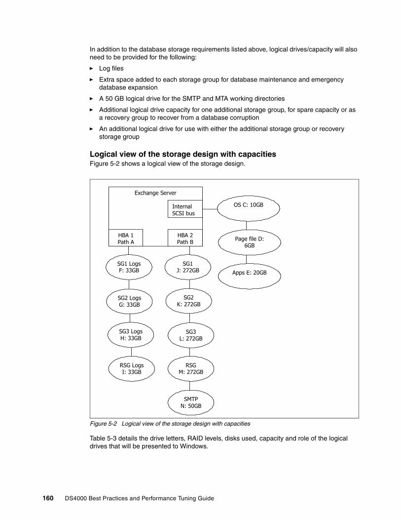
In addition to the database storage requirements listed above, logical drives/capacity will also need to be provided for the following:
� Log files
� Extra space added to each storage group for database maintenance and emergency database expansion
� A 50 GB logical drive for the SMTP and MTA working directories
� Additional logical drive capacity for one additional storage group, for spare capacity or as a recovery group to recover from a database corruption
� An additional logical drive for use with either the additional storage group or recovery storage group
Logical view of the storage design with capacitiesFigure 5-2 shows a logical view of the storage design.
Figure 5-2 Logical view of the storage design with capacities
Table 5-3 details the drive letters, RAID levels, disks used, capacity and role of the logical drives that will be presented to Windows.
OS C: 10GB
Page file D: 6GB
Apps E: 20GB
RSG Logs I: 33GB
Exchange Server
HBA 1 Path A
Internal SCSI bus
HBA 2 Path B
SG1 Logs F: 33GB
SG2 Logs G: 33GB
SG3 Logs H: 33GB
SG1 J: 272GB
SG2 K: 272GB
SG3 L: 272GB
RSG M: 272GB
SMTP N: 50GB
160 DS4000 Best Practices and Performance Tuning Guide
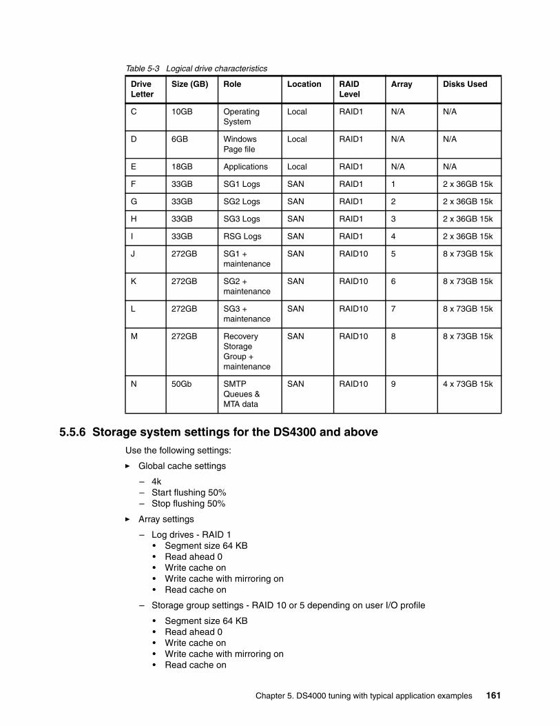
Table 5-3 Logical drive characteristics
5.5.6 Storage system settings for the DS4300 and aboveUse the following settings:
� Global cache settings
– 4k– Start flushing 50%– Stop flushing 50%
� Array settings
– Log drives - RAID 1• Segment size 64 KB• Read ahead 0• Write cache on• Write cache with mirroring on• Read cache on
– Storage group settings - RAID 10 or 5 depending on user I/O profile
• Segment size 64 KB• Read ahead 0• Write cache on• Write cache with mirroring on• Read cache on
Drive Letter
Size (GB) Role Location RAID Level
Array Disks Used
C 10GB Operating System
Local RAID1 N/A N/A
D 6GB Windows Page file
Local RAID1 N/A N/A
E 18GB Applications Local RAID1 N/A N/A
F 33GB SG1 Logs SAN RAID1 1 2 x 36GB 15k
G 33GB SG2 Logs SAN RAID1 2 2 x 36GB 15k
H 33GB SG3 Logs SAN RAID1 3 2 x 36GB 15k
I 33GB RSG Logs SAN RAID1 4 2 x 36GB 15k
J 272GB SG1 + maintenance
SAN RAID10 5 8 x 73GB 15k
K 272GB SG2 + maintenance
SAN RAID10 6 8 x 73GB 15k
L 272GB SG3 + maintenance
SAN RAID10 7 8 x 73GB 15k
M 272GB Recovery Storage Group + maintenance
SAN RAID10 8 8 x 73GB 15k
N 50Gb SMTP Queues & MTA data
SAN RAID10 9 4 x 73GB 15k
Chapter 5. DS4000 tuning with typical application examples 161
5.5.7 Aligning Exchange I/O with storage track boundariesWith a physical disk that maintains 64 sectors per track, Windows always creates the partition starting at the sixty-fourth sector, therefore misaligning it with the underlying physical disk. To be certain of disk alignment, use diskpart.exe, a disk partition tool. The diskpart.exe utility is provided by Microsoft in the Windows Server 2003 Service Pack 1 Support Tools that can explicitly set the starting offset in the master boot record (MBR). By setting the starting offset, you can track alignment and improve disk performance. Exchange Server 2003 writes data in multiples of 4 KB I/O operations (4 KB for the databases and up to 32 KB for streaming files). Therefore, make sure that the starting offset is a multiple of 4 KB. Failure to do so may cause a single I/O operation to span two tracks, causing performance degradation.
For more information, please refer to:
http://www.microsoft.com/technet/prodtechnol/exchange/guides/StoragePerformance/0e24eb22-fbd5-4536-9cb4-2bd8e98806e7.mspx.
The diskpart utility can only be used with basic disks, and it cannot be used with dynamic disks; diskpart supersedes the functionality previously found in diskpar.exe. Both diskpar and diskpart should only be used if the drive is translated as 64 sectors per track.
Additional considerationsIt is important in planning an Exchange configuration to recognize that disks not only provide capacity but determine performance.
After extensive testing, it has been proven that the log drives perform best on a RAID 1 mirrored pair.
In line with Microsoft Exchange best practices, it has also been proven that RAID 10 for storage groups outperforms other RAID configurations. That said, depending on the user profile, RAID 5 will provide the required IOPS performance in some instances.
Laying out the file system with diskpart provides additional performance improvements and also reduces the risk of performance degradation over time as the file system fills.
Dedicating HBAs for specific data transfer has a significant impact on performance. For example, HBA1 to controller A for log drives (sequential writes), and HBA 2 to controller B for storage groups (random read and writes).
Disk latency can be further reduced by adding additional HBAs to the server. Four (4) HBAs with logs and storage groups assigned to pairs of HBAs provided a significant reduction in disk latency and also reduces performance problems in the event of a path failure.
Important:The diskpart utility is data destructive. When used against a disk, all data on the disk will be wiped out during the storage track boundary alignment process. Therefore, if the disk on which you will run diskpart contains data, back up the disk before performing the following procedure.
162 DS4000 Best Practices and Performance Tuning Guide

The Windows performance monitor can be used effectively to monitor an active Exchange server. Here are the counters of interest:
� Average disk sec/write� Average disk sec/read� Current disk queue length� Disk transfers/sec
The average for the average disk sec/write and average disk sec/read on all database and log drives must be less than 20 ms.
The maximum of the average disk sec/write and average disk sec/read on all database and log drives must be less than 40 ms.
Chapter 5. DS4000 tuning with typical application examples 163

164 DS4000 Best Practices and Performance Tuning Guide

Chapter 6. Analyzing and measuring performance
When implementing a storage solution, whether it is directly attached to a server, connected to the enterprise network (NAS), or on its own network (SAN—Fibre Channel or iSCSI), it is important to know just how well the storage performs. If you do not have this information, growth is difficult since you can't properly manage it.
There are many different utilities and products that can help you measure and analyze performance. We introduce and review a few of them in this chapter:
� IOmeter� Xdd� Storage Manager Performance Monitor� SPA� Various AIX utilities� FAStT MSJ� MPPUTIL in Windows 2000/2003� Microsoft Windows Performance Monitor
6
© Copyright IBM Corp. 2005, 2006. All rights reserved. 165

6.1 Analyzing performanceTo determine where a performance problem exists, it is important to gather data from all the components of the storage solution. It is not uncommon to be misled by a single piece of information and lulled into a false sense of knowing the cause of a poor system performance, only to realize that another component of the system is truly the cause.
In this section we look at what utilities, tools and monitors are available to help you analyze what is actually happening within your environment.
As we have seen in Chapter 4, “DS4000 performance tuning” on page 113, storage applications can be categorized according to two types of workloads: transaction based or throughput based.
� Transaction performance is generally perceived to be poor when these conditions occur:
– Random reads/writes are exceeding 20ms (without write cache)– Random writes are exceeding 2ms with cache enabled– IOs are queueing up in the operating system IO stack (due to bottleneck)
� Throughput performance is generally perceived to be poor when the disk capability is not being reached. Causes of this can stem from the following situations:
– With reads, read-ahead is being limited, preventing higher amounts of immediate data available.
– IOs are queueing up in the operating system IO stack (due to bottleneck)
We discuss the following areas to consider:
� Gathering host server data� Gathering fabric network data� Gathering DS4000 storage server data
6.1.1 Gathering host server dataWhen gathering data from the host system(s) to analyze performance, it is important to gather the data from all host attached even though some may not be seeing any slowness. Indeed, a performant host may be impacting the others with its processing.
Gather all the statistics you can from the operating system tools and utilities. Data from these will help you when comparing them to what is seen with other measurement products. Utilities vary from operating system to operating system, so check with your administrators, or the operating system vendors.
Many UNIX type systems offer utilities that report disk IO statistics and system statistics like: iostat, sar, vmstat, filemon, nmon, and iozone to mention a few. All are very helpful with determining where the poor performance originates. With each of these commands you want to gather a sample period of statistics. Gathering one minute to 15 minutes worth of samples during the slow period will give you a fair sampling of data to review.
In the example shown in Figure 6-1, we see the following information:
� Interval time = (894 + 4 KB)/15 KBps = 60 sec� Average IO size = 227.8 KBps/26.9 tps = 8.5 KB � Estimated average IO service time = 0.054/26.9 tps = 2 ms� tps < 75 No IO bottleneck!� Disk service times good: No IO bottleneck� Disks not well balanced: hdisk0, hdisk1, hdisk5?
166 DS4000 Best Practices and Performance Tuning Guide
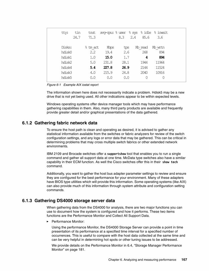
Figure 6-1 Example AIX iostat report
The information shown here does not necessarily indicate a problem. Hdisk5 may be a new drive that is not yet being used. All other indications appear to be within expected levels.
Windows operating systems offer device manager tools which may have performance gathering capabilities in them. Also, many third party products are available and frequently provide greater detail and/or graphical presentations of the data gathered.
6.1.2 Gathering fabric network dataTo ensure the host path is clean and operating as desired, it is advised to gather any statistical information available from the switches or fabric analyzers for review of the switch configuration settings, and any logs or error data that may be gathered. This can be critical in determining problems that may cross multiple switch fabrics or other extended network environments.
IBM 2109 and Brocade switches offer a supportshow tool that enables you to run a single command and gather all support data at one time. McData type switches also have a similar capability in their ECM function. As well the Cisco switches offer this in their show tech command.
Additionally, you want to gather the host bus adapter parameter settings to review and ensure they are configured for the best performance for your environment. Many of these adapters have BIOS type utilities which will provide this information. Some operating systems (like AIX) can also provide much of this information through system attribute and configuration setting commands.
6.1.3 Gathering DS4000 storage server dataWhen gathering data from the DS4000 for analysis, there are two major functions you can use to document how the system is configured and how it performs. These two items functions are the Performance Monitor and Collect All Support Data.
� Performance Monitor:
Using the performance Monitor, the DS4000 Storage Server can provide a point in time presentation of its performance at a specified time interval for a specified number of occurrences. This is useful to compare with the host data collected at the same time and can be very helpful in determining hot spots or other tuning issues to be addressed.
We provide details on the Performance Monitor in 6.4, “Storage Manager Performance Monitor” on page 181.
tty: tin tout avg-cpu: % user % sys % idle % iowait 24.7 71.3 8.3 2.4 85.6 3.6
Disks: % tm_act Kbps tps Kb_read Kb_wrtnhdisk0 2.2 19.4 2.6 268 894hdisk1 1.0 15.0 1.7 4 894hdisk2 5.0 231.8 28.1 1944 11964hdisk4 5.4 227.8 26.9 2144 11524hdisk3 4.0 215.9 24.8 2040 10916hdisk5 0.0 0.0 0.0 0 0
Chapter 6. Analyzing and measuring performance 167

� Collect All Support Data
This function can be run from the “IBM TotalStorage DS4000 Storage Manager Subsystem Management” window by selecting:
Advanced → TroubleShooting → Collect All Support Data
This will create a zip file of all the internal information of the DS4000 Storage Server for review by the support organization. This includes the storage Subsystems Profile, majorEventLog, driveDiagnosticData, NVSRAM data, readLinkStatus, performanceStatistics, and many others. This information, when combined and compared to the Performance Monitor data, will give a good picture of how the DS4000 Storage Server sees its workload being handled, and any areas it sees that are having trouble.
The performanceStatistics file provides you with a far greater amount of time coverage of data gathering, and a further breakout of the IO details of what the storage server’s workload has been. In this spreadsheet based log, you can see what your read and write ratio are for all the logical drives, controllers, and the storage server’s workload. Also, you can view the cache hits and misses for each type (read and write).
6.2 IometerIometer is a tool to generate workload and collect measurements for storage servers that are either directly attached or SAN attached to a host application server. Iometer was originally developed by Intel Corporation, and is now maintained and distributed under an Intel Open Source License; the tool is available for download at:
http://www.iometer.org
6.2.1 Iometer componentsIometer consists of two programs, Iometer and Dynamo:
� Iometer is the controlling program. It offers a graphical interface to define the workload, set operating parameters, and start and stop tests. It can be configured in a number of ways that allow very granular testing to take place so that it can test multiple scenarios. After completion of tests, it summarizes the results in output files. Only one instance of Iometer should be running at a time, typically on the server machine.
� Dynamo is the workload generator. It has no user interface. Dynamo performs I/O operations and records performance information as specified by Iometer, then returns the data to Iometer. There can be more than one copy of Dynamo running at a time and it must be installed on each system for which you would like to gather performance results.
Dynamo is multi-threaded; each copy can simulate the workload of multiple client programs. Each running copy of Dynamo is called a manager; each thread within a copy of Dynamo is called a worker.
For a list of supported platforms, refer to:
http://www.iometer.org/doc/matrix.html
Iometer is extraordinarily versatile; refer to the Iometer user guide for more information.
In the sections that follow, we go over some basic configurations and explain how to run tests locally.
168 DS4000 Best Practices and Performance Tuning Guide
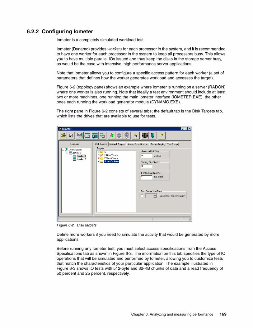
6.2.2 Configuring IometerIometer is a completely simulated workload test.
Iometer (Dynamo) provides workers for each processor in the system, and it is recommended to have one worker for each processor in the system to keep all processors busy. This allows you to have multiple parallel IOs issued and thus keep the disks in the storage server busy, as would be the case with intensive, high performance server applications.
Note that Iometer allows you to configure a specific access pattern for each worker (a set of parameters that defines how the worker generates workload and accesses the target).
Figure 6-2 (topology pane) shows an example where Iometer is running on a server (RADON) where one worker is also running. Note that ideally a test environment should include at least two or more machines, one running the main iometer interface (IOMETER.EXE), the other ones each running the workload generator module (DYNAMO.EXE).
The right pane in Figure 6-2 consists of several tabs; the default tab is the Disk Targets tab, which lists the drives that are available to use for tests.
Figure 6-2 Disk targets
Define more workers if you need to simulate the activity that would be generated by more applications.
Before running any Iometer test, you must select access specifications from the Access Specifications tab as shown in Figure 6-3. The information on this tab specifies the type of IO operations that will be simulated and performed by Iometer, allowing you to customize tests that match the characteristics of your particular application. The example illustrated in Figure 6-3 shows IO tests with 512-byte and 32-KB chunks of data and a read frequency of 50 percent and 25 percent, respectively.
Chapter 6. Analyzing and measuring performance 169

Figure 6-3 Access Specifications
To control precisely the access specifications, you can create new ones or edit existing ones by clicking the New or Edit buttons. See Figure 6-4.
Figure 6-4 Creating your own test
170 DS4000 Best Practices and Performance Tuning Guide

An access pattern contains the following variables:
� Transfer Request Size: A minimal data unit to which the test can apply.
� Percent Random/Sequential Distribution: Percentage of random requests. The other are, therefore, sequential.
� Percent Read/Write Distribution: Percentage of requests for reading: Another important variable which is not directly included in the access pattern — # of Outstanding IOs — defines a number of simultaneous I/O requests for the given worker and, correspondingly, the disk load.
This gives you enormous flexibility and allows very granular analysis of the performance by changing one parameter at a time from test to test.
The various access specifications you define can be saved (and reloaded) in a file (this is a text file with the extension .icf. You can copy/paste the sample shown, into your environment.
To load the file in Iometer, click the Open Test Configuration File icon. See Example 6-1.
Example 6-1 Access specification file for Iometer (workload.icf)
'Access specifications'Access specification name,default assignment2K OLTP,1'size,% of size,% reads,% random,delay,burst,align,reply2048,100,67,100,0,1,0,0'Access specification name,default assignment4K OLTP,1'size,% of size,% reads,% random,delay,burst,align,reply4096,100,67,100,0,1,0,0'Access specification name,default assignment8K OLTP,1'size,% of size,% reads,% random,delay,burst,align,reply8192,100,67,100,0,1,0,0'Access specification name,default assignment32 Byte Data Streaming Read,3'size,% of size,% reads,% random,delay,burst,align,reply32,100,100,0,0,1,0,0'Access specification name,default assignment32 Byte Data Streaming Write,3'size,% of size,% reads,% random,delay,burst,align,reply32,100,0,0,0,1,0,0'Access specification name,default assignment512 Byte Data Streaming Read,2'size,% of size,% reads,% random,delay,burst,align,reply512,100,100,0,0,1,0,0'Access specification name,default assignment512 Byte Data Streaming Write,2'size,% of size,% reads,% random,delay,burst,align,reply512,100,0,0,0,1,0,0'Access specification name,default assignment8K Data Streaming Read,3'size,% of size,% reads,% random,delay,burst,align,reply8192,100,100,0,0,1,0,0'Access specification name,default assignment8K Data Streaming Write,3'size,% of size,% reads,% random,delay,burst,align,reply8192,100,0,0,0,1,0,0'Access specification name,default assignment64K Data Streaming Read,1'size,% of size,% reads,% random,delay,burst,align,reply
Chapter 6. Analyzing and measuring performance 171

65536,100,100,0,0,1,0,0'Access specification name,default assignment64K Data Streaming Write,1'size,% of size,% reads,% random,delay,burst,align,reply65536,100,0,0,0,1,0,0'Access specification name,default assignmentTCP/IP Proxy Transfer,3'size,% of size,% reads,% random,delay,burst,align,reply350,100,100,100,0,1,0,11264'Access specification name,default assignmentFile Server,2'size,% of size,% reads,% random,delay,burst,align,reply512,10,80,100,0,1,0,01024,5,80,100,0,1,0,02048,5,80,100,0,1,0,04096,60,80,100,0,1,0,08192,2,80,100,0,1,0,016384,4,80,100,0,1,0,032768,4,80,100,0,1,0,065536,10,80,100,0,1,0,0'Access specification name,default assignmentWeb Server,2'size,% of size,% reads,% random,delay,burst,align,reply512,22,100,100,0,1,0,01024,15,100,100,0,1,0,02048,8,100,100,0,1,0,04096,23,100,100,0,1,0,08192,15,100,100,0,1,0,016384,2,100,100,0,1,0,032768,6,100,100,0,1,0,065536,7,100,100,0,1,0,0131072,1,100,100,0,1,0,0524288,1,100,100,0,1,0,0'End access specifications
The next step is to configure the Test Setup as shown in Figure 6-5. This allows you to set parameters, such as the length of the test. For example, if you want to get a true average reading of your disk system performance, you might want to run the test for hours instead of seconds to minimize the impact of possible events, such as a user pulling a large file from the system. Figure 6-5 shows what parameters can be adjusted.
172 DS4000 Best Practices and Performance Tuning Guide
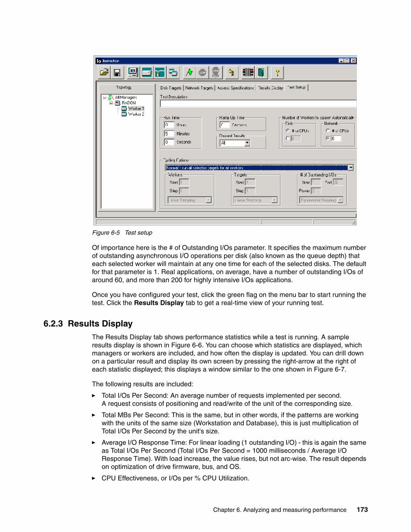
Figure 6-5 Test setup
Of importance here is the # of Outstanding I/Os parameter. It specifies the maximum number of outstanding asynchronous I/O operations per disk (also known as the queue depth) that each selected worker will maintain at any one time for each of the selected disks. The default for that parameter is 1. Real applications, on average, have a number of outstanding I/Os of around 60, and more than 200 for highly intensive I/Os applications.
Once you have configured your test, click the green flag on the menu bar to start running the test. Click the Results Display tab to get a real-time view of your running test.
6.2.3 Results DisplayThe Results Display tab shows performance statistics while a test is running. A sample results display is shown in Figure 6-6. You can choose which statistics are displayed, which managers or workers are included, and how often the display is updated. You can drill down on a particular result and display its own screen by pressing the right-arrow at the right of each statistic displayed; this displays a window similar to the one shown in Figure 6-7.
The following results are included:
� Total I/Os Per Second: An average number of requests implemented per second. A request consists of positioning and read/write of the unit of the corresponding size.
� Total MBs Per Second: This is the same, but in other words, if the patterns are working with the units of the same size (Workstation and Database), this is just multiplication of Total I/Os Per Second by the unit's size.
� Average I/O Response Time: For linear loading (1 outstanding I/O) - this is again the same as Total I/Os Per Second (Total I/Os Per Second = 1000 milliseconds / Average I/O Response Time). With load increase, the value rises, but not arc-wise. The result depends on optimization of drive firmware, bus, and OS.
� CPU Effectiveness, or I/Os per % CPU Utilization.
Chapter 6. Analyzing and measuring performance 173
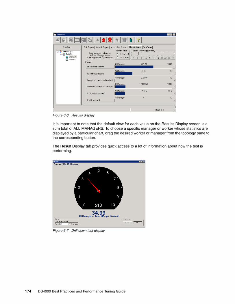
Figure 6-6 Results display
It is important to note that the default view for each value on the Results Display screen is a sum total of ALL MANAGERS. To choose a specific manager or worker whose statistics are displayed by a particular chart, drag the desired worker or manager from the topology pane to the corresponding button.
The Result Display tab provides quick access to a lot of information about how the test is performing.
Figure 6-7 Drill down test display
174 DS4000 Best Practices and Performance Tuning Guide

6.3 XddXdd is a tool for measuring and analyzing disk performance characteristics on single systems or clusters of systesms. It was designed by Thomas M. Ruwart from I/O Performance, Inc. to provide consistent and reproducible performance of a sustained transfer rate of an I/O subsystem. It is a command-line based tool that grew out of the UNIX world and has been ported to run in Window’s environments as well.
Xdd is a free software program distributed under a GNU General Public License. Xdd is available for download at:
http://www.ioperformance.com/products.htm
The Xdd distribution comes with all the source code necessary to install Xdd and the companion programs for the timeserver and the gettime utility programs.
6.3.1 Xdd components and mode of operationThere are three basic components to Xdd:
� The actual xdd program� The timeserver program� The gettime program.
The timeserver and gettime programs are used to synchronize the clocks of all the servers that run the xdd program simultaneously, providing a consistent time stamping to accurately correlate xdd events in multiple server systems (Figure 6-8).
Figure 6-8 Xdd components in a multiple server system
Chapter 6. Analyzing and measuring performance 175

Mode of operationXdd performs data transfer operations between memory and a disk device and collects performance information. Xdd creates one thread for every device or file under test. Each I/O operation is either a read or write operation of a fixed size known as the request size.
Multiple passes featureFor reproducibility of the results, an Xdd run must include several passes. Each pass executes some number of I/O requests on the specified target at the given request size. In general, each pass is identical to the previous passes in a run with respect to the request size, the number of requests to issue, and the access pattern. Passes are run one after another with no delay between passes unless a pass delay is specified.
Basic operationsXdd is invoked through a command line interface. All parameters must be specified upon invocation, either directly on the command line or through a setup file.
� The operation to perform is specified by the -op option and can be either read or write.
� You can mix read and write operations using the -rwratio parameter.
� The request size is specified by -reqsize in units of blocks (1024 bytes); the blocksize can be overridden by the -blocksize option.
� All requests are sent to a target (disk device or file), and an Xdd process can operate on single or multiple targets, specified through the -targets option.
� Each Xdd thread runs independently until it has either completed all its I/O operations (number of transfers -numreqs or number of Megabytes -mbytes) or reached a time limit (-timelimit option)
� Several options are also available to specify the type of access pattern desired (sequential, staggered sequential, or random).
The de-skew featureWhen testing a large number of devices (targets), there can be a significant delay between the time Xdd is started on the first target and the time it starts on the last one. Likewise, there will be a delay between when Xdd finishes on the first and last target. This causes the overall results to be skewed.
Xdd has a de-skew option that reports the bandwidth when all targets are active and transferring data (the amount of data transferred by any given target during the de-skew window is simply the total amount of data it actually transferred minus the data it transferred during the front-end skew period, and minus the data it transferred during the back-end skew period). The de-skewed data rate is the total amount of data transferred by all targets during the de-skew window, divided by the de-skew window time.
Read-behind-write featureXdd also has a read-behind-write feature. For the same target, Xdd can launch two threads: a writer thread, and a reader thread. After each record is written by the writer thread, it will block until the reader thread reads the record before it continues.
6.3.2 Compiling and installing XddAs part of our experiments in writing this book, we compiled an installed Xdd in an AIX environment.
176 DS4000 Best Practices and Performance Tuning Guide

To make Xdd, timeserver, and gettime in an AIX environment, first download the file xdd63-1.030305.tar.gz, then uncompress and extract the contents of the file with the gzip and tar commands respectively.
# gzip -d xdd63-1.030305.tar.gz# tar -xvf xdd63-1.030305.tar
Open the file with an editor or browser and look at the and of each line for a ^M special character; If it is found, it must be removed! See Figure 6-9.
Figure 6-9 Example of an unwanted end-of-line control character
The best solution is to transfer all files with ftp in binary mode to a Windows system and transfer the file again with ftp in ascii mode.
Once the file is corrected (no ^M end of line), you can compile by issuing the following command:
# make –f aix.makefile all
This uses the xlc compiler and associated libraries. Ensure that the required libraries are installed for correct compilation and linking.
Verify the required filesets with:
# lslpp -l | grep vacvac.C 6.0.0.0 COMMITTED C for AIX Compilervac.C.readme.ibm 6.0.0.0 COMMITTED C for AIX iFOR/LS Informationvac.lic 6.0.0.0 COMMITTED C for AIX Licence Filesvac.msg.en_US.C 6.0.0.0 COMMITTED C for AIX Compiler Messages -vac.C 6.0.0.0 COMMITTED C for AIX Compiler
Important: Verify the file aix.makefile before execution. It may contain undesirable control characters.
End Of Line WRONG
Chapter 6. Analyzing and measuring performance 177
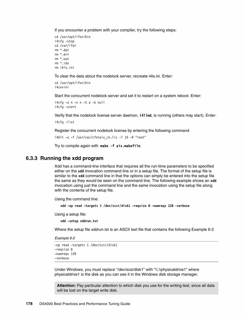
If you encounter a problem with your compiler, try the following steps:
cd /usr/opt/ifor/bin i4cfg -stop cd /var/ifor rm *.dat rm *.err rm *.out rm *.idx rm i4ls.ini
To clear the data about the nodelock server, recreate i4ls.ini. Enter:
cd /usr/opt/ifor/bin i4cnvini
Start the concurrent nodelock server and set it to restart on a system reboot. Enter:
i4cfg -a n -n n -S a -b null i4cfg -start
Verify that the nodelock license server daemon, i4llmd, is running (others may start). Enter:
i4cfg -list
Register the concurrent nodelock license by entering the following command
i4blt -a -f /usr/vac/cforaix_cn.lic -T 10 -R "root"
Try to compile again with make -f aix.makefile.
6.3.3 Running the xdd programXdd has a command-line interface that requires all the run-time parameters to be specified either on the xdd invocation command line or in a setup file. The format of the setup file is similar to the xdd command line in that the options can simply be entered into the setup file the same as they would be seen on the command line. The following example shows an xdd invocation using just the command line and the same invocation using the setup file along with the contents of the setup file.
Using the command line:
xdd –op read –targets 1 /dev/scsi/disk1 –reqsize 8 –numreqs 128 –verbose
Using a setup file:
xdd –setup xddrun.txt
Where the setup file xddrun.txt is an ASCII text file that contains the following Example 6-2
Example 6-2
–op read –targets 1 /dev/scsi/disk1–reqsize 8–numreqs 128-verbose
Under Windows, you must replace “/dev/scsi/disk1” with “\\.\\physicaldrive1” where physicaldrive1 is the disk as you can see it in the Windows disk storage manager.
Attention: Pay particular attention to which disk you use for the writing test, since all data will be lost on the target write disk.
178 DS4000 Best Practices and Performance Tuning Guide

Xdd examples in WindowsEnter the following command:
xdd –op read –targets 1 \\.\\physicaldrive3 –reqsize 128 -mbytes 64 –passes 3 –verbose
This is a very basic test that will read sequentially from target device disk 3 starting at block 0 using a fixed request size of 128 blocks until it has read 64 megabytes.
It will do this 3 times and display performance information for each pass. The default block size is 1024 bytes per block, so the request size in bytes is 128 KB (128 * 1024 bytes).
Please note that all these options need to be on a single command line unless they are in the setup file, where they can be on separate lines.
Xdd examples in AIXAfter compilation, the xdd executable file for AIX resides in the bin directory. In our case, it is called xdd.aix and is under /IBM/xdd/xdd62c/bin.
./xdd.aix -op read -targets 1 /dev/hdisk3 -reqsize 128 -mbytes 4 -passes 5 -verbose
This command will read sequentially from target disk /dev/hdisk3 starting at block0 using a fixed request size of 128 blocks, until il has read 4 Mb (4*1024*1024 bytes). The command runs for five times (passes) and displays performance information for each pass.
Example 6-3 Xdd example in AIX
Seconds before starting, 0 T Q Bytes Ops Time Rate IOPS Latency %CPUTARGET PASS0001 0 1 4194304 32 0.087 48.122 367.15 0.0027 22.22TARGET PASS0002 0 1 4194304 32 0.087 48.201 367.74 0.0027 37.50TARGET PASS0003 0 1 4194304 32 0.086 48.494 369.98 0.0027 33.33TARGET PASS0004 0 1 4194304 32 0.087 48.397 369.24 0.0027 22.22TARGET PASS0005 0 1 4194304 32 0.087 48.393 369.21 0.0027 75.00TARGET Average 0 1 20971520 16 0.434 48.321 368.66 0.0027 37.21 Combined 1 1 20971520 16 0.434 48.321 368.66 0.0027 37.21Ending time for this run, Wed Nov 9 07:43:58 2005
Below, we compare the latency value between an internal SCSI disk (hdisk2)and an FC disk (hdisk4) in a DS4000 storage server. For this test, we use hdisk2 for internal SCSI and hdisk4 for DS4000 fibre disk.
Example 6-4 Xdd example fo SCSI disk in AIX
./xdd.aix -op read -targets 1 /dev/hdisk2 -reqsize 128 -mbytes 256 -passes 5 -verbose
Seconds before starting, 0 T Q Bytes Ops Time Rate IOPS Latency %CPUTARGET PASS0001 0 1 268435456 2048 9.486 28.298 215.89 0.0046 26.87TARGET PASS0002 0 1 268435456 2048 9.476 28.327 216.12 0.0046 25.95TARGET PASS0003 0 1 268435456 2048 9.476 28.327 216.12 0.0046 26.50TARGET PASS0004 0 1 268435456 2048 9.476 28.327 216.12 0.0046 27.22TARGET PASS0005 0 1 268435456 2048 9.483 28.306 215.96 0.0046 27.11TARGET Average 0 1 1342177280 10240 47.399 28.317 216.04 0.0046 26.73 Combined 1 1 1342177280 10240 47.399 28.317 216.04 0.0046 26.73Ending time for this run, Wed Nov 9 08:06:30 2005
Chapter 6. Analyzing and measuring performance 179
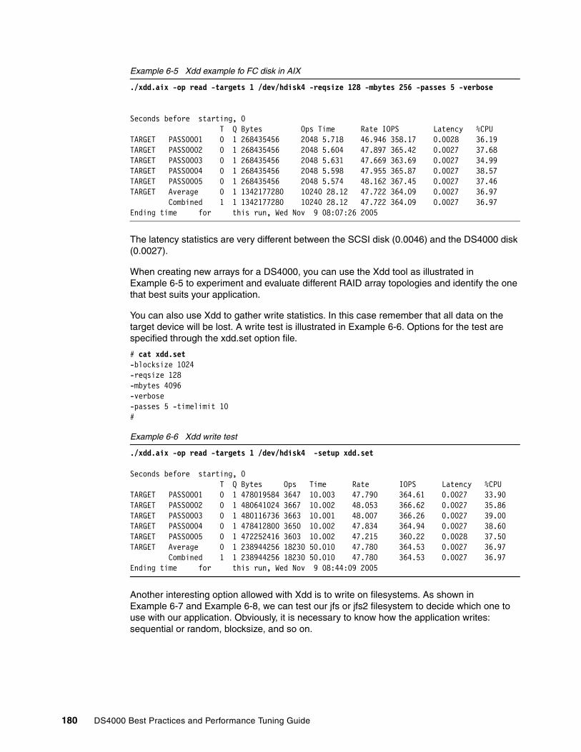
Example 6-5 Xdd example fo FC disk in AIX
./xdd.aix -op read -targets 1 /dev/hdisk4 -reqsize 128 -mbytes 256 -passes 5 -verbose
Seconds before starting, 0 T Q Bytes Ops Time Rate IOPS Latency %CPUTARGET PASS0001 0 1 268435456 2048 5.718 46.946 358.17 0.0028 36.19TARGET PASS0002 0 1 268435456 2048 5.604 47.897 365.42 0.0027 37.68TARGET PASS0003 0 1 268435456 2048 5.631 47.669 363.69 0.0027 34.99TARGET PASS0004 0 1 268435456 2048 5.598 47.955 365.87 0.0027 38.57TARGET PASS0005 0 1 268435456 2048 5.574 48.162 367.45 0.0027 37.46TARGET Average 0 1 1342177280 10240 28.12 47.722 364.09 0.0027 36.97 Combined 1 1 1342177280 10240 28.12 47.722 364.09 0.0027 36.97Ending time for this run, Wed Nov 9 08:07:26 2005
The latency statistics are very different between the SCSI disk (0.0046) and the DS4000 disk (0.0027).
When creating new arrays for a DS4000, you can use the Xdd tool as illustrated in Example 6-5 to experiment and evaluate different RAID array topologies and identify the one that best suits your application.
You can also use Xdd to gather write statistics. In this case remember that all data on the target device will be lost. A write test is illustrated in Example 6-6. Options for the test are specified through the xdd.set option file.
# cat xdd.set-blocksize 1024-reqsize 128-mbytes 4096-verbose-passes 5 -timelimit 10#
Example 6-6 Xdd write test
./xdd.aix -op read -targets 1 /dev/hdisk4 -setup xdd.set
Seconds before starting, 0 T Q Bytes Ops Time Rate IOPS Latency %CPUTARGET PASS0001 0 1 478019584 3647 10.003 47.790 364.61 0.0027 33.90TARGET PASS0002 0 1 480641024 3667 10.002 48.053 366.62 0.0027 35.86TARGET PASS0003 0 1 480116736 3663 10.001 48.007 366.26 0.0027 39.00TARGET PASS0004 0 1 478412800 3650 10.002 47.834 364.94 0.0027 38.60TARGET PASS0005 0 1 472252416 3603 10.002 47.215 360.22 0.0028 37.50TARGET Average 0 1 238944256 18230 50.010 47.780 364.53 0.0027 36.97 Combined 1 1 238944256 18230 50.010 47.780 364.53 0.0027 36.97Ending time for this run, Wed Nov 9 08:44:09 2005
Another interesting option allowed with Xdd is to write on filesystems. As shown in Example 6-7 and Example 6-8, we can test our jfs or jfs2 filesystem to decide which one to use with our application. Obviously, it is necessary to know how the application writes: sequential or random, blocksize, and so on.
180 DS4000 Best Practices and Performance Tuning Guide

Example 6-7 Xdd write on jfs filesystem
./xdd.aix -op write -targets 1 /fsds3J1/file3 -blocksize 512 -reqsize 128 -mbytes 64 \ -verbose -passes 3
Seconds before starting, 0 T Q Bytes Ops Time Rate IOPS Latency %CPUTARGET PASS0001 0 1 67108864 1024 0.188 356.918 5446.14 0.0002 100.00TARGET PASS0002 0 1 67108864 1024 0.582 115.391 1760.72 0.0006 27.59TARGET PASS0003 0 1 67108864 1024 0.557 120.576 1839.85 0.0005 33.93TARGET Average 0 1 20132659 3072 1.326 151.810 2316.44 0.0004 40.60 Combined 1 1 20132659 3072 1.326 151.810 2316.44 0.0004 40.60Ending time for this run, Wed Nov 9 09:27:12 2005
Example 6-8 Xdd write on jfs2 filesystem
./xdd.aix -op write -targets 1 /fsds1J2/file1 -blocksize 512 -reqsize 128 -mbytes\ 64 -verbose -passes 3
Seconds before starting, 0 T Q Bytes Ops Time Rate IOPS Latency %CPUTARGET PASS0001 0 1 67108864 1024 0.463 144.970 2212.07 0.0005 82.61TARGET PASS0002 0 1 67108864 1024 0.203 330.603 5044.61 0.0002 100.00TARGET PASS0003 0 1 67108864 1024 0.314 213.443 3256.88 0.0003 78.12TARGET Average 0 1 201326592 3072 0.980 205.369 3133.69 0.0003 84.69 Combined 1 1 201326592 3072 0.980 205.369 3133.69 0.0003 84.69Ending time for this run, Wed Nov 9 09:31:46 2005
6.4 Storage Manager Performance MonitorThe Storage PerformaNce Monitor is a tool built into the DS4000 Storage Manager client. It monitors performance on each logical drive, and collects information such as:
� Total I/Os� Read percentage� Cache hit percentage� Current KB/sec and maximum KB/sec� Current I/O per sec and maximum I/O per sec
This section describes how to use data from the Performance Monitor and what tuning options are available in the Storage Manager for optimizing the Storage Server performance.
6.4.1 Starting the Performance MonitorYou launch the Performance Monitor from the SMclient Subsystem Management window by either:
� Selecting the Monitor Performance icon
or
� Selecting the Storage Subsystem → Monitor Performance pull-down menu option
� Selecting the storage subsystem node in the Logical View or Mappings View, then choosing Monitor Performance from the right-mouse pop-up menu
Chapter 6. Analyzing and measuring performance 181

The Performance Monitor window opens up with all logical drives displayed as shown in Figure 6-10.
Figure 6-10 Performance Monitor
Table 6-1 describes the information collected by the Performance Monitor.
Table 6-1 Information collected by Performance Monitor
� Total I/Os:
This data is useful for monitoring the I/O activity of a specific controller and a specific logical drive, which can help identify possible high-traffic I/O areas.
If I/O rate is slow on a logical drive, try increasing the array size.
Data field Description
Total I/Os Total I/Os performed by this device since the beginning of the polling session.
Read percentage
The percentage of total I/Os that are read operations for this device. Write percentage can be calculated as 100 minus this value.
Cache hit percentage
The percentage of reads that are processed with data from the cache rather than requiring a read from disk.
Current KBps Average transfer rate during the polling session. The transfer rate is the amount of data in Kilobytes that can be moved through the I/O Data connection in a second (also called throughput).
Maximum KBps
The maximum transfer rate that was achieved during the Performance Monitor polling session.
Current I/O per second
The average number of I/O requests serviced per second during the current polling interval (also called an I/O request rate).
Maximum I/O per second
The maximum number of I/O requests serviced during a one-second interval over the entire polling session.
182 DS4000 Best Practices and Performance Tuning Guide

You might notice a disparity in the Total I/Os (workload) of controllers, for example, the workload of one controller is heavy or is increasing over time, while that of the other controller is lighter or more stable. In this case, consider changing the controller ownership of one or more logical drives to the controller with the lighter workload. Use the logical drive Total I/O statistics to determine which logical drives to move.
If you notice that the workload across the storage subsystem (Storage Subsystem Totals Total I/O statistic) continues to increase over time, while application performance decreases, this might indicate the need to add additional storage subsystems to your installation so that you can continue to meet application needs at an acceptable performance level.
� Read percentage:
Use the read percentage for a logical drive to determine actual application behavior. If there is a low percentage of read activity relative to write activity, consider changing the RAID level of an array from RAID-5 to RAID-1 for faster performance.
� Cache hit percentage:
A higher percentage is desirable for optimal application performance. There is a positive correlation between the cache hit percentage and I/O rates.
The cache hit percentage of all of the logical drives might be low or trending downward. This might indicate inherent randomness in access patterns, or at the storage subsystem or controller level, this can indicate the need to install more controller cache memory if you do not have the maximum amount of memory installed.
If an individual logical drive is experiencing a low cache hit percentage, consider enabling cache read ahead for that logical drive. Cache read ahead can increase the cache hit percentage for a sequential I/O workload.
Determining the effectiveness of a logical drive cache read-ahead multiplier
To determine if your I/O has sequential characteristics, try enabling a conservative cache read-ahead multiplier (four, for example). Then, examine the logical drive cache hit percentage to see if it has improved. If it has, indicating that your I/O has a sequential pattern, enable a more aggressive cache read-ahead multiplier (eight, for example). Continue to customize logical drive cache read-ahead to arrive at the optimal multiplier (in the case of a random I/O pattern, the optimal multiplier is zero).
� Current KB/sec and maximum KB/sec:
The “Current KB/sec” value is the average size of the amount of data that was transfer over one second during a particular “interval period” that was monitored. The “Maximum KB/sec” value is the highest amount that was transferred over any one second period, during all of the interval periods in the “number of iterations” that were ran for a specific command. This value can show you when peak transfer rate period was detected during the command runtime.
The transfer rates of the controller are determined by the application I/O size and the I/O rate. Generally, small application I/O requests result in a lower transfer rate, but provide a faster I/O rate and shorter response time. With larger application I/O requests, higher throughput rates are possible. Understanding your typical application I/O patterns can help you determine the maximum I/O transfer rates for a given storage subsystem.
Tip: If Maximum KB/sec is the same as last interval’s Current KB/sec, we recommend extending the number of iterations to see when the peak rate is actually reached, as this may be on the rise.
Chapter 6. Analyzing and measuring performance 183

Consider a storage subsystem, equipped with Fibre Channel controllers, that supports a maximum transfer rate of 100 Mbps (100,000 KB per second). Your storage subsystem typically achieves an average transfer rate of 20,000 KB/sec. (The typical I/O size for your applications is 4 KB, with 5,000 I/Os transferred per second for an average rate of 20,000 KB/sec.) In this case, I/O size is small. Because there is system overhead associated with each I/O, the transfer rates will not approach 100,000 KB/sec. However, if your typical I/O size is large, a transfer rate within a range of 80,000 to 90,000 KB/sec might be achieved.
� Current I/O per second and maximum I/O per second:
The Current IO/sec value is the average number of IOs serviced in one second during a particular interval period that was monitored. The Maximum IO/sec value is the highest number of IOs serviced in any one second period, during all of the interval periods in the number of iterations that were ran for a specific command. This value can show you when the peak IO period was detected during the command runtime.
Factors that affect I/Os per second include access pattern (random or sequential), I/O size, RAID level, segment size, and number of drives in the arrays or storage subsystem. The higher the cache hit rate, the higher the I/O rates.
Performance improvements caused by changing the segment size can be seen in the I/Os per second statistics for a logical drive. Experiment to determine the optimal segment size, or use the file system or database block size.
Higher write I/O rates are experienced with write caching enabled compared to disabled. In deciding whether to enable write caching for an individual logical drive, consider the current and maximum I/Os per second. You should expect to see higher rates for sequential I/O patterns than for random I/O patterns. Regardless of your I/O pattern, we recommend that write caching be enabled to maximize I/O rate and shorten application response time.
6.4.2 Using the Performance MonitorThe Performance Monitor queries the Storage subsystem at regular intervals. To change the polling interval and to select only the logical drives and the controllers you wish to monitor, click the Settings button.
To change the polling interval, choose a number of seconds in the spin box. Each time the polling interval elapses, the Performance Monitor re-queries the storage subsystem and updates the statistics in the table. If you are monitoring the storage subsystem in real time, update the statistics frequently by selecting a short polling interval, for example, five seconds. If you are saving results to a file to look at later, choose a slightly longer interval, for example, 30 to 60 seconds, to decrease the system overhead and the performance impact.
The Performance Monitor will not dynamically update its display if any configuration changes occur while the monitor window is open (for example, creation of new logical drives, change in logical drive ownership, and so on). The Performance Monitor window must be closed and then reopened for the changes to appear.
Tip: If Maximum IO/sec is the same as the last interval’s Current IO/sec, we recommend extending the number of iterations to see when the peak is actually reached, as this may be on the rise.
Note: Using the Performance Monitor to retrieve performance data can affect the normal storage subsystem performance, depending on how many items you want to monitor and the refresh interval.
184 DS4000 Best Practices and Performance Tuning Guide
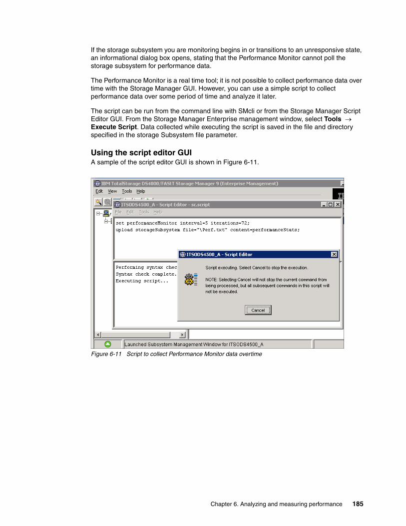
If the storage subsystem you are monitoring begins in or transitions to an unresponsive state, an informational dialog box opens, stating that the Performance Monitor cannot poll the storage subsystem for performance data.
The Performance Monitor is a real time tool; it is not possible to collect performance data over time with the Storage Manager GUI. However, you can use a simple script to collect performance data over some period of time and analyze it later.
The script can be run from the command line with SMcli or from the Storage Manager Script Editor GUI. From the Storage Manager Enterprise management window, select Tools → Execute Script. Data collected while executing the script is saved in the file and directory specified in the storage Subsystem file parameter.
Using the script editor GUIA sample of the script editor GUI is shown in Figure 6-11.
Figure 6-11 Script to collect Performance Monitor data overtime
Chapter 6. Analyzing and measuring performance 185

A sample of the output file is shown in Figure 6-12.
Figure 6-12 Script output file
Using the Command Line Interface CLIYou can also use the SMcli to gather Performance Monitor data over a period of time. Example 6-9 shows a test_script file for execution under AIX, using the ksh test_script:
# cat test_script
Example 6-9 Test script
#!/bin/ksh#The information is captured from a single Linux/Aix server by running the# following "Storage Manager Command Line Interface Utility" Linux/Aix commandCMD='set session performanceMonitorInterval=60 performanceMonitorIterations=2; \ show allLogicalDrives performanceStats;'/usr/SMclient/SMcli -e -S 9.1.39.26 9.1.39.27 -c "$CMD"#(Note; this will get you a run every minute for 2 time; if run every 10 minutes for 10 # times set the# "performanceMonitorinterval=600"# "performanceMonitorIterations=10"
The first executable line sets the CMD variable; the second executable line invokes the SMcli command. Note that for the -S parameter, it is necessary to specify the IP address of both DS4000 Controllers (A and B).
The output resulting from the script execution can be redirected to a file by typing the command: ksh test_script > test_output.
186 DS4000 Best Practices and Performance Tuning Guide
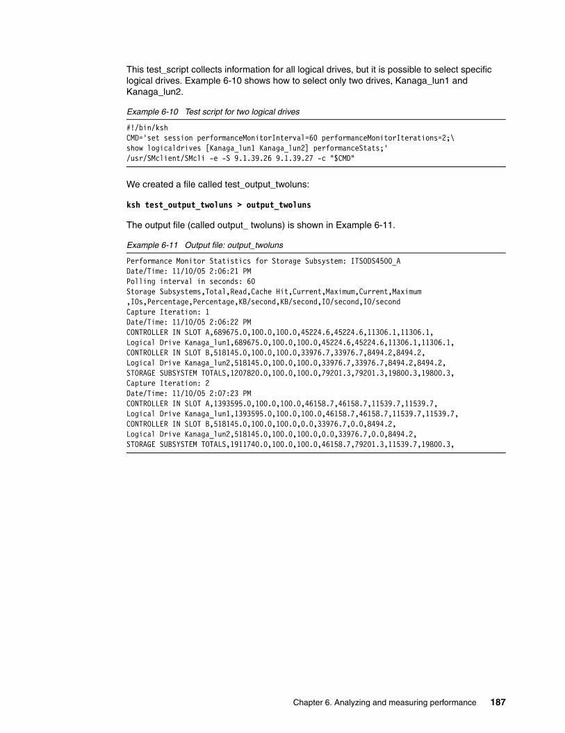
This test_script collects information for all logical drives, but it is possible to select specific logical drives. Example 6-10 shows how to select only two drives, Kanaga_lun1 and Kanaga_lun2.
Example 6-10 Test script for two logical drives
#!/bin/kshCMD='set session performanceMonitorInterval=60 performanceMonitorIterations=2;\ show logicaldrives [Kanaga_lun1 Kanaga_lun2] performanceStats;'/usr/SMclient/SMcli -e -S 9.1.39.26 9.1.39.27 -c "$CMD"
We created a file called test_output_twoluns:
ksh test_output_twoluns > output_twoluns
The output file (called output_ twoluns) is shown in Example 6-11.
Example 6-11 Output file: output_twoluns
Performance Monitor Statistics for Storage Subsystem: ITSODS4500_ADate/Time: 11/10/05 2:06:21 PMPolling interval in seconds: 60Storage Subsystems,Total,Read,Cache Hit,Current,Maximum,Current,Maximum,IOs,Percentage,Percentage,KB/second,KB/second,IO/second,IO/secondCapture Iteration: 1Date/Time: 11/10/05 2:06:22 PMCONTROLLER IN SLOT A,689675.0,100.0,100.0,45224.6,45224.6,11306.1,11306.1,Logical Drive Kanaga_lun1,689675.0,100.0,100.0,45224.6,45224.6,11306.1,11306.1,CONTROLLER IN SLOT B,518145.0,100.0,100.0,33976.7,33976.7,8494.2,8494.2,Logical Drive Kanaga_lun2,518145.0,100.0,100.0,33976.7,33976.7,8494.2,8494.2,STORAGE SUBSYSTEM TOTALS,1207820.0,100.0,100.0,79201.3,79201.3,19800.3,19800.3,Capture Iteration: 2Date/Time: 11/10/05 2:07:23 PMCONTROLLER IN SLOT A,1393595.0,100.0,100.0,46158.7,46158.7,11539.7,11539.7,Logical Drive Kanaga_lun1,1393595.0,100.0,100.0,46158.7,46158.7,11539.7,11539.7,CONTROLLER IN SLOT B,518145.0,100.0,100.0,0.0,33976.7,0.0,8494.2,Logical Drive Kanaga_lun2,518145.0,100.0,100.0,0.0,33976.7,0.0,8494.2,STORAGE SUBSYSTEM TOTALS,1911740.0,100.0,100.0,46158.7,79201.3,11539.7,19800.3,
Chapter 6. Analyzing and measuring performance 187

All the data saved in the file is comma delimited so that the file can be easily imported into a spreadsheet for easier analysis and review (Figure 6-13).
Figure 6-13 Importing results into a spreadsheet
The following is a description of all the values saved.
6.4.3 Using the Performance Monitor: IllustrationTo illustrate the use of the Performance Monitor, we suppose that we want to find the optimal value for the max_xref_size parameter of an HBA.
We ran several tests with different values of the parameter. The test environment consists of the following components: DS4500, AIX5.2, Brocade switch.
Two LUNs, Kanaga_lun0 and Kanaga_lun1 of 20Gb each, are defined on DS45000 and reside in separate arrays. Kanaga_lun0 is in array 10, defined as RAID 0 and consists of three physical drives; Kanaga_lun1is in Array 11 (RAID 0) with four physical drives. Kanaga_lun0 is on the preferred controller B, and kanaga_lun1 is on controller A (Figure 6-14).
188 DS4000 Best Practices and Performance Tuning Guide

Figure 6-14 Logical/Physical view of test LUNs
We assign to LUNs to AIX, create one volume group, DS4000vg, with 32 PPSize and create two different logical volumes: lvkana1 with 600 Physical Partitions on hdisk 3 “lun Kanaga_lun1” and lvkana2 with 600 Physical Partitions on hdisk4 “lun Kanaga_lun0” (Figure 6-15).
Figure 6-15 AIX volumes and volume group
Chapter 6. Analyzing and measuring performance 189
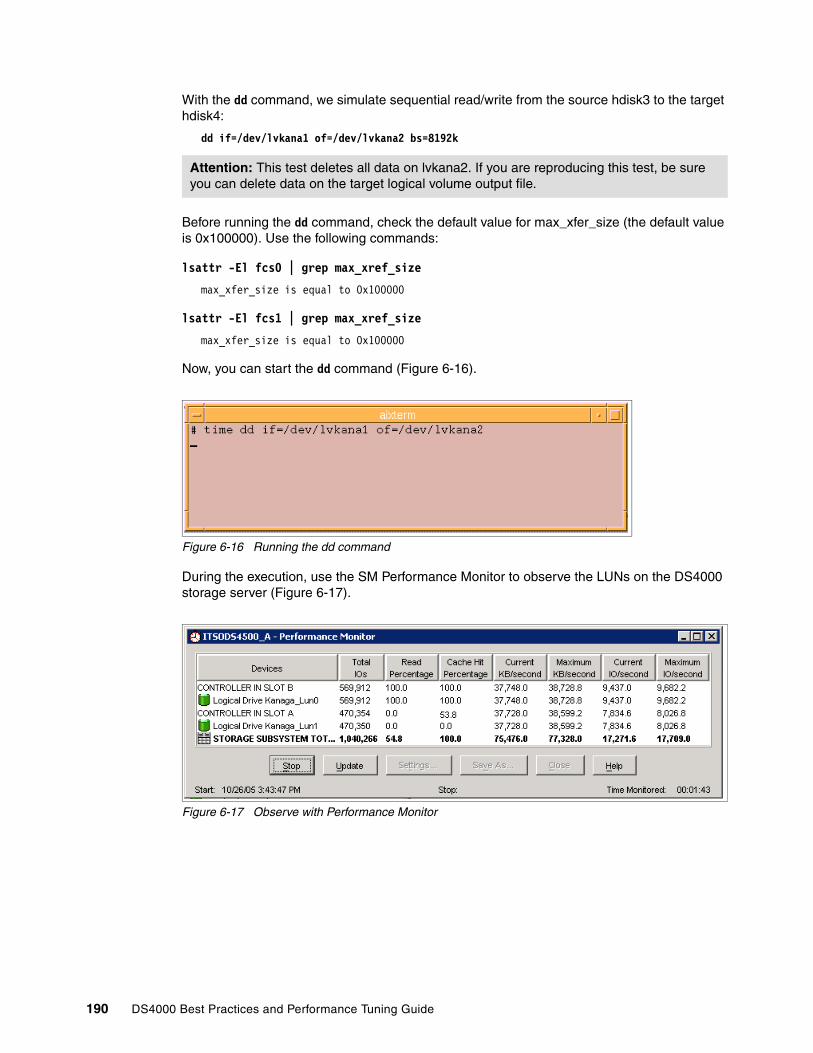
With the dd command, we simulate sequential read/write from the source hdisk3 to the target hdisk4:
dd if=/dev/lvkana1 of=/dev/lvkana2 bs=8192k
Before running the dd command, check the default value for max_xfer_size (the default value is 0x100000). Use the following commands:
lsattr -El fcs0 | grep max_xref_size
max_xfer_size is equal to 0x100000
lsattr -El fcs1 | grep max_xref_size
max_xfer_size is equal to 0x100000
Now, you can start the dd command (Figure 6-16).
Figure 6-16 Running the dd command
During the execution, use the SM Performance Monitor to observe the LUNs on the DS4000 storage server (Figure 6-17).
Figure 6-17 Observe with Performance Monitor
Attention: This test deletes all data on lvkana2. If you are reproducing this test, be sure you can delete data on the target logical volume output file.
190 DS4000 Best Practices and Performance Tuning Guide

Upon termination, the dd command indicates how long it took to make the copy (Figure 6-18).
Figure 6-18 dd output
Now, using a simple script called chxfer and shown in Example 6-12, we change the value of max_xfer_size for the two HBAs (Example 6-12).
Example 6-12 Script chxfer
if [[ $1 -eq 100 || $1 -eq 200 || $1 -eq 400 || $1 -eq 1000 ]]then varyoffvg DS4000vg rmdev -dl dar0 -R rmdev -dl fscsi0 -R rmdev -dl fscsi1 -R chdev -l fcs0 -a max_xfer_size=0x"$1"000 chdev -l fcs1 -a max_xfer_size=0x"$1"000 cfgmgr varyonvg DS4000vgelse echo "paramitter value not valid. use 100 200 400 1000"fi
The script does a varyoffvg for the DS4000vg volume group, removes all drivers under fcs0 and fcs1, changes the max_xfer_size value on both fcs adapters, and reconfigures all devices. These steps are necessary to set a new max_xfer_size value on the adapters.
Run the script by entering (at the AX command line):
# ksh chxfer 200
Restart the dd test and look at the results using the Performance Monitor (Figure 6-19).
Figure 6-19 New observation in Performance Monitor
Operating system copy time
Chapter 6. Analyzing and measuring performance 191

Again, note the time upon completion of the dd command (Figure 6-20).
Figure 6-20 dd command with max_xfer_size set to 0x200000
Repeat the steps for other values of the max_xfer_size parameter and collect the results as shown in Table 6-2. Now we are able to analyze the copy time.
Table 6-2 Results for dd command
In our example, the best value for max_xfer_Size is 0x200000. Although this does not get the lowest time for executing the dd command, it performs the IO operations more efficiently.
Now we can run another test for a big sequential I/O. In the previous test we used the /dev/lvkana1 and /dev/lvkana2 “block access device” in which case AIX generates sequential block of 4Kb for read and write. In this new test we use /dev/rlvkana1 and /dev/rlvkana2 “raw access device” for which AIX generates sequential blocks of 8192Kb.
Results of the two tests for the same value of max_xfer_size are shown in Table 6-3.
Table 6-3 Test results - max_xfer_size
You can see a significant time reduction for the copy operation, using the same value recommended before of 0x200000, but changing the block size from 4K to 8 MB. The 8 MB block allows for much greater throughput than the 4K block.
With the SM Performance Monitor you can view which controller works, and can then decide to move some volumes from one controller to the other to balance the performance among controllers.
You can also see if some LUNs work more than others (on the same host), and can then decide if possible to move data from on one logical drive to another to balance the throughput among the drives. Note, however, that the Performance Monitor cannot show the throughput for a physical drive. For that purpose, you can use the Storage Performance Analyzer (see 6.5, “Storage Performance Analyzer (SPA)” on page 193).
max_xfer_size time dd command SM perform max I/O SM current kb/s
0x100000 8min 37.87 sec 8,026 38,599
0x200000 8min 37.32 sec 17,962 78,236
0x400000 8min 36.60 sec 17,954 83,761
0x1000000 8min 36.76 sec 17,772 77,363
max_xfer_size time dd command SM perform max I/O Sm current kb/s
0x200000 Block 4K 8min 37.68 sec 3,600 - 3,800 38,000
0x200000 Row 8192K 3min 41.24 sec 88,000 - 90,000 901,000
192 DS4000 Best Practices and Performance Tuning Guide

6.5 Storage Performance Analyzer (SPA)The Storage Performance Analyzer (SPA) is a stand-alone program that complements the DS4000 Storage Manager.
SPA integrates the management of applications, servers, storage networks, and storage subsystems in a single, easy to implement, and intuitive solution. It relies upon Common Information Model (CIM) / Web Enterprise Based Management (WBEM) / Storage Management Initiative (SMI) standards to eliminate most vendor dependencies and view and manage the storage infrastructure as a whole.
By giving administrators a single, integrated console to manage tactical activities such as provisioning storage, managing real time events, installing new applications, and migrating servers and storage, as well as strategic activities such as forecasting, planning, and cost analysis, SPA can lower the cost of acquiring and managing a heterogeneous storage environment.
SPA keeps all its statistics in an Oracle based database. This stores all the information gathered, so that trending analysis can be undertaken.
SPA is one of the few products that gives physical disk statistics. This allows for much more information gathering other than just the LUN based real time statistics you get with the Storage Management Performance Monitor.
Physical disk statistics can greatly assist in troubleshooting performance related problems, as each disk can be monitored to report all operations performed.
6.5.1 Product architecture and componentsSPA ships with the following software:
1. Management Server: The management server provides various tools to let you monitor and manage your SAN devices.
It includes the following features:
– Event Manager: Event Manager lets you view, clear, sort and filter events from managed elements. An event can be anything that occurs on the element, such as a device connected to a Brocade switch that has gone off-line.
– Performance Explorer: Performance Explorer provides a graphical representation of the performance history of an element, such as number of bytes transmitted per second for a switch.
– System Explorer: System Explorer is the gateway to many features that lets you view details about the discovered elements. System Explorer provides a topology that lets you view how the devices in your network are connected.
2. Provider: A provider is a software application that is used to gather information about an element (host, switch, or Storage System). It resides on the management server and converts proprietary API calls to CIM.
Tip: SPA is one of the few products that gives you physical disk statistics.
Note: The Management Server is available only on Windows operating systems.
Chapter 6. Analyzing and measuring performance 193

3. CIM Extensions: A CIM Extension is a Java based binary that gathers information from the operating system and host bus adapters. It then makes the information available to the SPA management server. Refer to the SPA Installation Guide product for information on how to install the CIM Extensions (Figure 6-21).
Figure 6-21 SPA overview
SPA architectureThe Manager Server uses an Ethernet connection to communicate with CIM Extensions, and supports the following operating systems:
� IBM AIX� SGI IRIX � Sun Solaris � Microsoft Windows
The CIM Extension communicates with an HBA by using the Host Bus Adapter Application Programming Interface (HBAAPI) created by the Storage Network Industry Association (SNIA). The management server only supports communication with HBAs that are compliant with the HBAAPI. For more information about the HBAAPI, see the following Web page at the SNIA Web Site:
http://www.snia.org/tech_activities/hba_api/
The CIM Extension gathers information from the operating system and host bus adapters. It then makes the information available to the management server, by communicating to the CIM via a host provider.
194 DS4000 Best Practices and Performance Tuning Guide
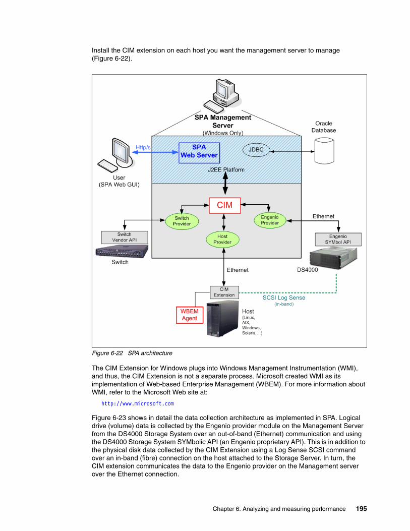
Install the CIM extension on each host you want the management server to manage (Figure 6-22).
Figure 6-22 SPA architecture
The CIM Extension for Windows plugs into Windows Management Instrumentation (WMI), and thus, the CIM Extension is not a separate process. Microsoft created WMI as its implementation of Web-based Enterprise Management (WBEM). For more information about WMI, refer to the Microsoft Web site at:
http://www.microsoft.com
Figure 6-23 shows in detail the data collection architecture as implemented in SPA. Logical drive (volume) data is collected by the Engenio provider module on the Management Server from the DS4000 Storage System over an out-of-band (Ethernet) communication and using the DS4000 Storage System SYMbolic API (an Engenio proprietary API). This is in addition to the physical disk data collected by the CIM Extension using a Log Sense SCSI command over an in-band (fibre) connection on the host attached to the Storage Server. In turn, the CIM extension communicates the data to the Engenio provider on the Management server over the Ethernet connection.
Chapter 6. Analyzing and measuring performance 195

Figure 6-23 SPA - Data collection architecture
6.5.2 Using SPATo use SPA, you access the management server through a Web browser. Simply type one of the following URLs in a Web browser:
� For secure connections:
https://machinenamewhere machinename is the name of the management server.
� For non-secure connections:
http://machinenamewhere machinename is the name of the management server.
This will display the login window as shown in Figure 6-24.
Figure 6-24 Login to the SPA server
SPAManagementServer
EngenioProvider
Host CIM Extension:Aix, Solaris, Windows
DS4000 Storage
Subsystem
Log Sense
SYMbol API
In-Band
Out-of-Band
Ethernet
196 DS4000 Best Practices and Performance Tuning Guide

Enter the username “admin” along with the password that was assigned during the SPA setup and click Login. The SPA Welcome panel displays (Figure 6-25).
Figure 6-25 SPA Welcome panel
Note that the product documentation is available online, by selecting Help, then Documentation Center. This gives you access to the two guides:
� Storage Performance Analyzer Installation Guide � Storage Performance Analyzer User Guide
Discovering Switches and Storage SystemsBefore you can use the management server, you must make the software aware of the elements on your network. An element is anything on the network that can be detected by the management server, such as a switch. This is done through the discovery process.
Discovery obtains a list of discovered elements and information about their management interface and dependencies. The management server can discover only elements with a suitable management interface. Refer to the support matrix for supported hardware.
First discover the switches and storage systems on your network. After discovery, install the CIM Extensions. Then, discover your hosts, as described next in “Discovering hosts” on page 198.
Discovery consists of three steps:
� Setting up: Finding the elements on the network.
� Topology: Mapping the elements in the topology.
� Details: Obtaining detailed element information. This step takes some time to perform, but can run unattended.
Chapter 6. Analyzing and measuring performance 197
Discovering CNT switchesThe management server uses the CNT SMI-S provider to discover CNT switches. A provider is a small software program that is used by the management server to communicate with a device, such as a switch.
Discovering Cisco switchesThe management server discovers Cisco switches through an SNMP connection. When you discover a Cisco switch, you do not need to provide a password.
Discovering McDATA switchesMcDATA switches use the Fibre Channel Switch Application Programming Interface (SWAPI) to communicate with devices on the network. The management server can discover multiple instances of Enterprise Fabric Connectivity Manager.
Discovering Storage SystemsKeep in mind the following considerations when discovering a storage system:
� Discover all controllers on a storage system by entering the IP address of each controller.
� The management server must have the User Name field populated to discover the storage system. If your storage system does not have a user name set, you must enter something in the User Name field, even though the storage system has no user name.
� Discover both controllers for the storage system. Each controller has its own IP address. In Step 1 of discovery (setup), specify all the IP addresses for all the controllers (usually two). The management server discovers these controllers as one single storage system.
� To obtain drive-related statistics, install a proxy host. Ensure the proxy host has at least one LUN rendered by each controller of the array. For more information, see the SPA Installation Guide.
� A license key is required for each storage system. The key must be obtained from the Web site specified on the Activation Card that shipped with your storage system.
Discovering hostsYou discover hosts in the same way you discovered your switches and storage systems. You provide the host’s IP address, user name, and password. The user name and password must have administrative privileges. Unlike switches and storage systems, you must have installed CIM Extension on the host if you want to obtain detailed information about the host.
Keep in mind the following considerations:
� If you change the password of a host after you discover it, you must change the password for the host in the discovery list. Then, you must stop and restart the CIM Extension running on that host.
� If your license lets you discover UNIX and/or Linux hosts, the Test button for discovery reports SUCCESS from any UNIX and/or Linux hosts on which the management server can detect a CIM Extension. The CIM Extension must be running. The management server reports “SUCCESS” even if your license restricts you from discovering certain types of hosts. For example, assume that your license lets you discover Solaris hosts but not AIX hosts. If you click the Test button, the management server reports “SUCCESS” for the AIX hosts. However, you will not be able to discover the AIX hosts. The IP address is not discoverable, because of the license limitation.
198 DS4000 Best Practices and Performance Tuning Guide

Removing elements from the Addresses to Discover listWhen you remove IP addresses and/or ranges from the Addresses to Discover list, the elements associated with those IP addresses are not removed from the management server.
Only the information that was used to discover them is removed.
System ExplorerThe System Explorer shows all the discovered systems (Figure 6-26).
Figure 6-26 System Explorer window
Chapter 6. Analyzing and measuring performance 199

From the explored systems, you can drill down inside an element for more information about that element (Figure 6-27).
Figure 6-27 Expanded details of a host
Element detailsIn the System Explorer, when you click on an element, a new window containing several tabs with the details of that element opens up. The top level tabs in the new window are:
� Navigation:
The Navigation tab not only provides information about an element, but it also illustrates how the element relates to other elements in its path. For example, the Navigation page displays logical and physical components, such as ports, zone sets, zones and zone aliases. It also displays the dependencies for switches, as shown in the following figure.
� Properties:
The Properties tab provides detailed information about an element. Since the information obtained from each type of element varies, the Properties tab displays information only relevant for that type of element. For example, the Properties tab for fabrics lists the zones, zone sets, switches, and zone aliases, as compared to the Properties tab for a host, which lists the processors, cards, applications, and storage volumes the host uses.
200 DS4000 Best Practices and Performance Tuning Guide
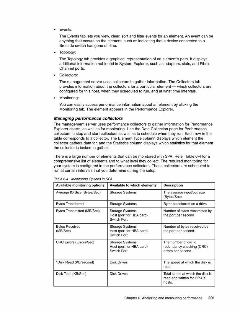
� Events:
The Events tab lets you view, clear, sort and filter events for an element. An event can be anything that occurs on the element, such as indicating that a device connected to a Brocade switch has gone off-line.
� Topology:
The Topology tab provides a graphical representation of an element's path. It displays additional information not found in System Explorer, such as adapters, slots, and Fibre Channel ports.
� Collectors:
The management server uses collectors to gather information. The Collectors tab provides information about the collectors for a particular element — which collectors are configured for this host, when they scheduled to run, and at what time intervals.
� Monitoring:
You can easily access performance information about an element by clicking the Monitoring tab. The element appears in the Performance Explorer.
Managing performance collectorsThe management server uses performance collectors to gather information for Performance Explorer charts, as well as for monitoring. Use the Data Collection page for Performance collectors to stop and start collectors as well as to schedule when they run. Each row in the table corresponds to a collector. The Element Type column displays which element the collector gathers data for, and the Statistics column displays which statistics for that element the collector is tasked to gather.
There is a large number of elements that can be monitored with SPA. Refer Table 6-4 for a comprehensive list of elements and to what level they collect. The required monitoring for your system is configured in the performance collectors. These collectors are scheduled to run at certain intervals that you determine during the setup.
Table 6-4 Monitoring Options in SPA
Available monitoring options Available to which elements Description
Average IO Size (Bytes/Sec) Storage Systems The average input/out size (Bytes/Sec)
Bytes Transferred Storage Systems Bytes transferred on a drive
Bytes Transmitted (MB/Sec) Storage SystemsHost (port for HBA card)Switch Port
Number of bytes transmitted by the port per second
Bytes Received(MB/Sec)
Storage SystemsHost (port for HBA card)Switch Port
Number of bytes received by the port per second.
CRC Errors (Errors/Sec) Storage SystemsHost (port for HBA card)Switch Port
The number of cyclic redundancy checking (CRC) errors per second.
*Disk Read (KB/second) Disk Drives The speed at which the disk is read.
Disk Total (KB/Sec) Disk Drives Total speed at which the disk is read and written for HP-UX hosts.
Chapter 6. Analyzing and measuring performance 201
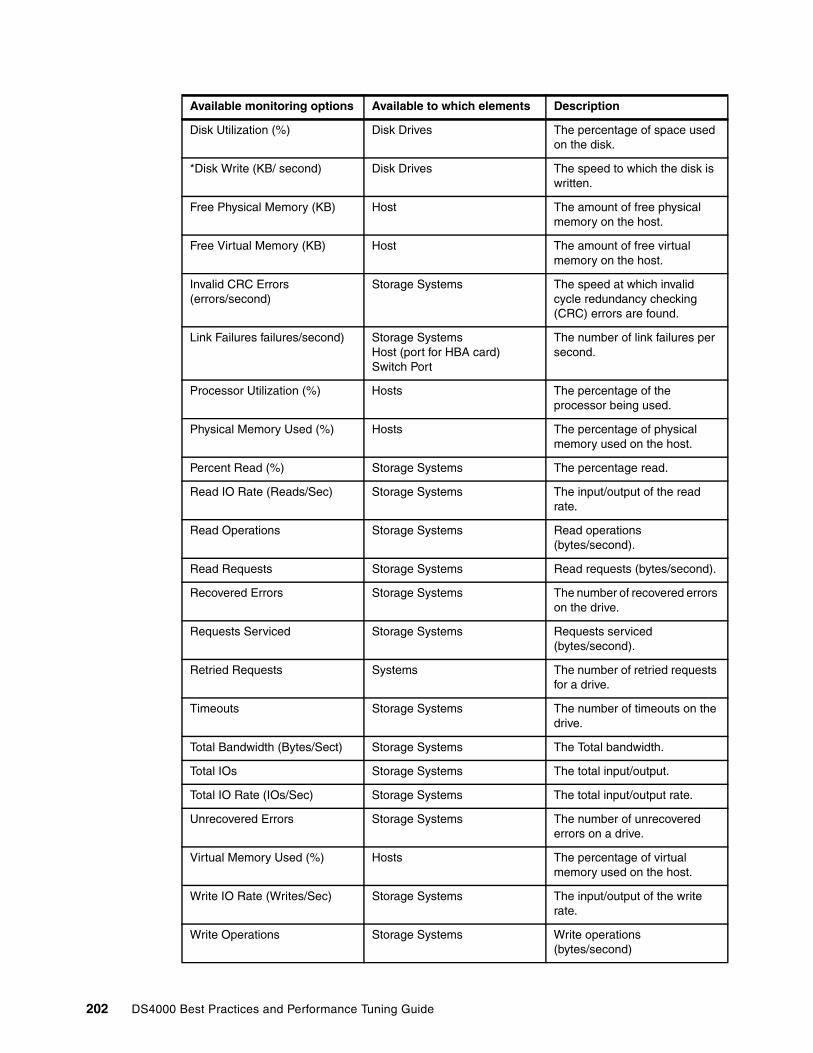
Disk Utilization (%) Disk Drives The percentage of space used on the disk.
*Disk Write (KB/ second) Disk Drives The speed to which the disk is written.
Free Physical Memory (KB) Host The amount of free physical memory on the host.
Free Virtual Memory (KB) Host The amount of free virtual memory on the host.
Invalid CRC Errors (errors/second)
Storage Systems The speed at which invalid cycle redundancy checking (CRC) errors are found.
Link Failures failures/second) Storage SystemsHost (port for HBA card)Switch Port
The number of link failures per second.
Processor Utilization (%) Hosts The percentage of the processor being used.
Physical Memory Used (%) Hosts The percentage of physical memory used on the host.
Percent Read (%) Storage Systems The percentage read.
Read IO Rate (Reads/Sec) Storage Systems The input/output of the read rate.
Read Operations Storage Systems Read operations (bytes/second).
Read Requests Storage Systems Read requests (bytes/second).
Recovered Errors Storage Systems The number of recovered errors on the drive.
Requests Serviced Storage Systems Requests serviced (bytes/second).
Retried Requests Systems The number of retried requests for a drive.
Timeouts Storage Systems The number of timeouts on the drive.
Total Bandwidth (Bytes/Sect) Storage Systems The Total bandwidth.
Total IOs Storage Systems The total input/output.
Total IO Rate (IOs/Sec) Storage Systems The total input/output rate.
Unrecovered Errors Storage Systems The number of unrecovered errors on a drive.
Virtual Memory Used (%) Hosts The percentage of virtual memory used on the host.
Write IO Rate (Writes/Sec) Storage Systems The input/output of the write rate.
Write Operations Storage Systems Write operations (bytes/second)
Available monitoring options Available to which elements Description
202 DS4000 Best Practices and Performance Tuning Guide

Viewing performance dataTo view the performance data that has been collected by the SPA server, click the PerfExplorer tab (Figure 6-28).
Figure 6-28 Performance Explorer Window
When the topology map appears, click the host for which you want to view the performance data.
Chapter 6. Analyzing and measuring performance 203
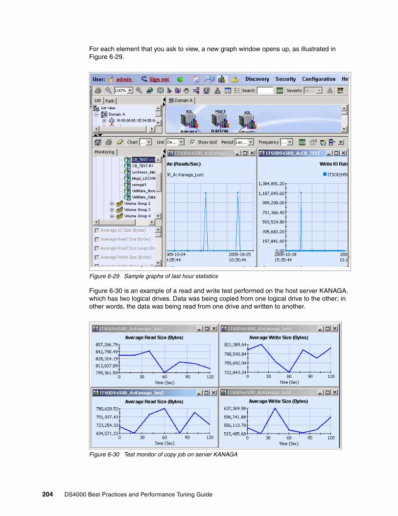
For each element that you ask to view, a new graph window opens up, as illustrated in Figure 6-29.
Figure 6-29 Sample graphs of last hour statistics
Figure 6-30 is an example of a read and write test performed on the host server KANAGA, which has two logical drives. Data was being copied from one logical drive to the other; in other words, the data was being read from one drive and written to another.
Figure 6-30 Test monitor of copy job on server KANAGA
204 DS4000 Best Practices and Performance Tuning Guide
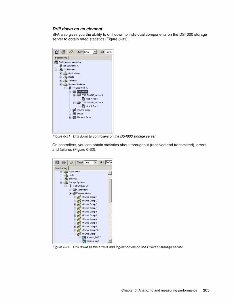
Drill down on an elementSPA also gives you the ability to drill down to individual components on the DS4000 storage server to obtain rated statistics (Figure 6-31).
Figure 6-31 Drill down to controllers on the DS4000 storage server
On controllers, you can obtain statistics about throughput (received and transmitted), errors, and failures (Figure 6-32).
Figure 6-32 Drill down to the arrays and logical drives on the DS4000 storage server
Chapter 6. Analyzing and measuring performance 205

Within an array (in SPA, these are called Volume Groups), you can drill down to individual logical drives to obtain statistics (Figure 6-33).
Figure 6-33 Drill down to individual drives on the DS4000 storage server
For logical drives, you can further drill down to the individual (physical) disk drives to obtain drive level statistics. Figure 6-34 and Figure 6-35 show examples of several real time statistics observed on a specific physical drive. To obtain all the drive statistics for a volume group (array), you must first know all the drives that make up that logical drive. This information can be obtained from Storage Manager.
Figure 6-34 Real time drive statistics for Total Bandwidth and Percent read on single disk
206 DS4000 Best Practices and Performance Tuning Guide

Figure 6-35 Real time drive write IO Rate on single disk
Figure 6-36 and Figure 6-37 show examples of read bandwidth being observed over time on a logical disk drive (kanaga-lun2).
Figure 6-36 Drill down to the logical drive and select a statistic that you wish to monitor
Chapter 6. Analyzing and measuring performance 207
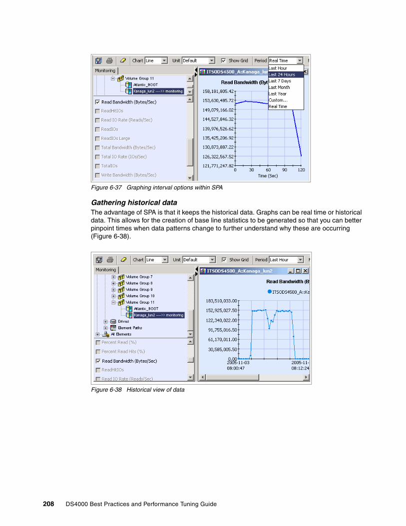
Figure 6-37 Graphing interval options within SPA
Gathering historical dataThe advantage of SPA is that it keeps the historical data. Graphs can be real time or historical data. This allows for the creation of base line statistics to be generated so that you can better pinpoint times when data patterns change to further understand why these are occurring (Figure 6-38).
Figure 6-38 Historical view of data
208 DS4000 Best Practices and Performance Tuning Guide

Event managerThe Event Manager shows all the events collected by the SPA server. These events can be filtered by severity level and element type. You can configure SPA to keep all events or to prune information out of the database when it reaches a certain age (Figure 6-39).
Figure 6-39 Event Manager
Updating the SPA serverWhen changes are made to the storage system, such as adding new hosts or logical drives, SPA must be updated to reflect the changes. The SPA server will not discover the changes dynamically.
For new devices, they must be added to the server, and then a discovery must be done.
Additional informationFor further information about SPA, see the Engenio Web site:
http://www.engenio.com
Or contact your local authorized reseller.
6.6 AIX utilitiesThis section reviews several command and utilities that are part of the AIX operating system and can be used to analyze storage performance. For details, please refer to the AIX Performance Management Guide, SC23-4876.
Chapter 6. Analyzing and measuring performance 209
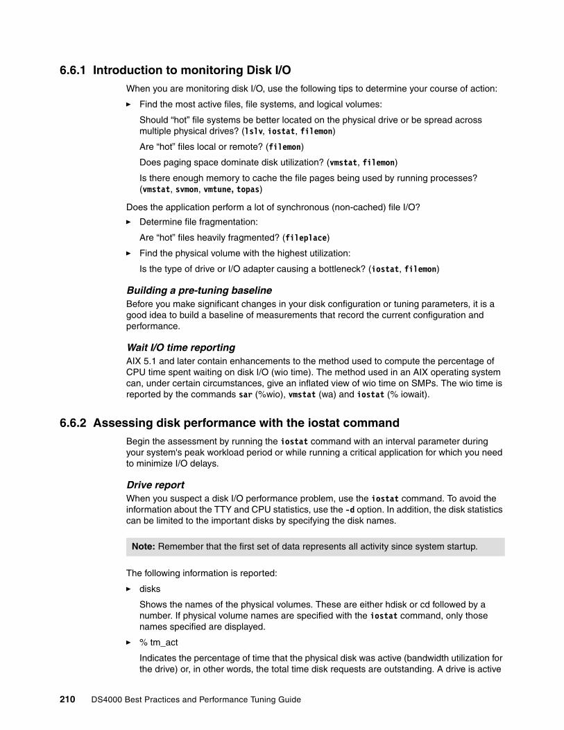
6.6.1 Introduction to monitoring Disk I/OWhen you are monitoring disk I/O, use the following tips to determine your course of action:
� Find the most active files, file systems, and logical volumes:
Should “hot” file systems be better located on the physical drive or be spread across multiple physical drives? (lslv, iostat, filemon)
Are “hot” files local or remote? (filemon)
Does paging space dominate disk utilization? (vmstat, filemon)
Is there enough memory to cache the file pages being used by running processes? (vmstat, svmon, vmtune, topas)
Does the application perform a lot of synchronous (non-cached) file I/O?
� Determine file fragmentation:
Are “hot” files heavily fragmented? (fileplace)
� Find the physical volume with the highest utilization:
Is the type of drive or I/O adapter causing a bottleneck? (iostat, filemon)
Building a pre-tuning baselineBefore you make significant changes in your disk configuration or tuning parameters, it is a good idea to build a baseline of measurements that record the current configuration and performance.
Wait I/O time reportingAIX 5.1 and later contain enhancements to the method used to compute the percentage of CPU time spent waiting on disk I/O (wio time). The method used in an AIX operating system can, under certain circumstances, give an inflated view of wio time on SMPs. The wio time is reported by the commands sar (%wio), vmstat (wa) and iostat (% iowait).
6.6.2 Assessing disk performance with the iostat commandBegin the assessment by running the iostat command with an interval parameter during your system's peak workload period or while running a critical application for which you need to minimize I/O delays.
Drive reportWhen you suspect a disk I/O performance problem, use the iostat command. To avoid the information about the TTY and CPU statistics, use the -d option. In addition, the disk statistics can be limited to the important disks by specifying the disk names.
The following information is reported:
� disks
Shows the names of the physical volumes. These are either hdisk or cd followed by a number. If physical volume names are specified with the iostat command, only those names specified are displayed.
� % tm_act
Indicates the percentage of time that the physical disk was active (bandwidth utilization for the drive) or, in other words, the total time disk requests are outstanding. A drive is active
Note: Remember that the first set of data represents all activity since system startup.
210 DS4000 Best Practices and Performance Tuning Guide

during data transfer and command processing, such as seeking to a new location. The “disk active time” percentage is directly proportional to resource contention and inversely proportional to performance. As disk use increases, performance decreases and response time increases. In general, when the utilization exceeds 70 percent, processes are waiting longer than necessary for I/O to complete because most UNIX processes block (or sleep) while waiting for their I/O requests to complete. Look for busy versus idle drives. Moving data from busy to idle drives can help alleviate a disk bottleneck. Paging to and from disk will contribute to the I/O load.
� Kbps
Indicates the amount of data transferred (read or written) to the drive in KB per second. This is the sum of Kb_read plus Kb_wrtn, divided by the seconds in the reporting interval.
� tps
Indicates the number of transfers per second that were issued to the physical disk. A transfer is an I/O request through the device driver level to the physical disk. Multiple logical requests can be combined into a single I/O request to the disk. A transfer is of indeterminate size.
� Kb_read
Reports the total data (in KB) read from the physical volume during the measured interval.
� Kb_wrtn
Shows the amount of data (in KB) written to the physical volume during the measured interval.
Taken alone, there is no unacceptable value for any of the above fields because statistics are too closely related to application characteristics, system configuration, and type of physical disk drives and adapters. Therefore, when you are evaluating data, look for patterns and relationships. The most common relationship is between disk utilization (%tm_act) and data transfer rate (tps).
To draw any valid conclusions from this data, you have to understand the application's disk data access patterns such as sequential, random, or combination, as well as the type of physical disk drives and adapters on the system. For example, if an application reads/writes sequentially, you should expect a high disk transfer rate (Kbps) when you have a high disk busy rate (%tm_act). Columns Kb_read and Kb_wrtn can confirm an understanding of an application's read/write behavior. However, these columns provide no information on the data access patterns.
Generally you do not need to be concerned about a high disk busy rate (%tm_act) as long as the disk transfer rate (Kbps) is also high. However, if you get a high disk busy rate and a low disk transfer rate, you may have a fragmented logical volume, file system, or individual file.
Discussions of disk, logical volume and file system performance sometimes lead to the conclusion that the more drives you have on your system, the better the disk I/O performance. This is not always true because there is a limit to the amount of data that can be handled by a disk adapter. The disk adapter can also become a bottleneck. If all your disk drives are on one disk adapter, and your hot file systems are on separate physical volumes, you might benefit from using multiple disk adapters. Performance improvement will depend on the type of access.
To see if a particular adapter is saturated, use the iostat command and add up all the Kbps amounts for the disks attached to a particular disk adapter. For maximum aggregate performance, the total of the transfer rates (Kbps) must be below the disk adapter throughput rating. In most cases, use 70 percent of the throughput rate, the -a or -A option will display this information.
Chapter 6. Analyzing and measuring performance 211
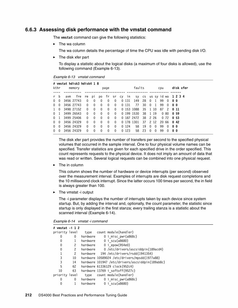
6.6.3 Assessing disk performance with the vmstat commandThe vmstat command can give the following statistics:
� The wa column
The wa column details the percentage of time the CPU was idle with pending disk I/O.
� The disk xfer part
To display a statistic about the logical disks (a maximum of four disks is allowed), use the following command (Example 6-13).
Example 6-13 vmstat command
# vmstat hdisk3 hdisk4 1 8kthr memory page faults cpu disk xfer---- ---------- ----------------------- ------------ ----------- ------r b avm fre re pi po fr sr cy in sy cs us sy id wa 1 2 3 40 0 3456 27743 0 0 0 0 0 0 131 149 28 0 1 99 0 0 00 0 3456 27743 0 0 0 0 0 0 131 77 30 0 1 99 0 0 01 0 3498 27152 0 0 0 0 0 0 153 1088 35 1 10 87 2 0 110 1 3499 26543 0 0 0 0 0 0 199 1530 38 1 19 0 80 0 590 1 3499 25406 0 0 0 0 0 0 187 2472 38 2 26 0 72 0 530 0 3456 24329 0 0 0 0 0 0 178 1301 37 2 12 20 66 0 420 0 3456 24329 0 0 0 0 0 0 124 58 19 0 0 99 0 0 00 0 3456 24329 0 0 0 0 0 0 123 58 23 0 0 99 0 0 0
The disk xfer part provides the number of transfers per second to the specified physical volumes that occurred in the sample interval. One to four physical volume names can be specified. Transfer statistics are given for each specified drive in the order specified. This count represents requests to the physical device. It does not imply an amount of data that was read or written. Several logical requests can be combined into one physical request.
� The in column
This column shows the number of hardware or device interrupts (per second) observed over the measurement interval. Examples of interrupts are disk request completions and the 10 millisecond clock interrupt. Since the latter occurs 100 times per second, the in field is always greater than 100.
� The vmstat -i output
The -i parameter displays the number of interrupts taken by each device since system startup. But, by adding the interval and, optionally, the count parameter, the statistic since startup is only displayed in the first stanza; every trailing stanza is a statistic about the scanned interval (Example 6-14).
Example 6-14 vmstat -i command
# vmstat -i 1 2priority level type count module(handler) 0 0 hardware 0 i_misc_pwr(a868c) 0 1 hardware 0 i_scu(a8680) 0 2 hardware 0 i_epow(954e0) 0 2 hardware 0 /etc/drivers/ascsiddpin(189acd4) 1 2 hardware 194 /etc/drivers/rsdd(1941354) 3 10 hardware 10589024 /etc/drivers/mpsdd(1977a88) 3 14 hardware 101947 /etc/drivers/ascsiddpin(189ab8c) 5 62 hardware 61336129 clock(952c4) 10 63 hardware 13769 i_softoff(9527c)priority level type count module(handler) 0 0 hardware 0 i_misc_pwr(a868c) 0 1 hardware 0 i_scu(a8680)
212 DS4000 Best Practices and Performance Tuning Guide

0 2 hardware 0 i_epow(954e0) 0 2 hardware 0 /etc/drivers/ascsiddpin(189acd4) 1 2 hardware 0 /etc/drivers/rsdd(1941354) 3 10 hardware 25 /etc/drivers/mpsdd(1977a88) 3 14 hardware 0 /etc/drivers/ascsiddpin(189ab8c) 5 62 hardware 105 clock(952c4) 10 63 hardware 0 i_softoff(9527c)
6.6.4 Assessing disk performance with the sar commandThe sar command is a standard UNIX command used to gather statistical data about the system. With its numerous options, the sar command provides queuing, paging, TTY, and many other statistics. With AIX, the sar -d option generates real-time disk I/O statistics (Example 6-15).
Example 6-15 sar command
# sar -d 3 3 AIX konark 3 4 0002506F4C00 08/26/9912:09:50 device %busy avque r+w/s blks/s avwait avserv12:09:53 hdisk0 1 0.0 0 5 0.0 0.0 hdisk1 0 0.0 0 1 0.0 0.0 cd0 0 0.0 0 0 0.0 0.012:09:56 hdisk0 0 0.0 0 0 0.0 0.0 hdisk1 0 0.0 0 1 0.0 0.0 cd0 0 0.0 0 0 0.0 0.012:09:59 hdisk0 1 0.0 1 4 0.0 0.0 hdisk1 0 0.0 0 1 0.0 0.0 cd0 0 0.0 0 0 0.0 0.0Average hdisk0 0 0.0 0 3 0.0 0.0 hdisk1 0 0.0 0 1 0.0 0.0 cd0 0 0.0 0 0 0.0 0.0
The fields listed by the sar -d command are as follows:
� %busy
Portion of time device was busy servicing a transfer request. This is the same as the %tm_act column in the iostat command report.
� avque
Average number of requests outstanding during that time. This number is a good indicator if an I/O bottleneck exists.
� r+w/s
Number of read/write transfers from or to device. This is the same as tps in the iostat command report.
� blks/s
Number of bytes transferred in 512-byte units
Note: The output will differ from system to system, depending on hardware and software configurations (for example, the clock interrupts may not be displayed in the vmstat -i output although they will be accounted for under the in column in the normal vmstat output). Check for high numbers in the count column and investigate why this module has to execute so many interrupts.
Chapter 6. Analyzing and measuring performance 213
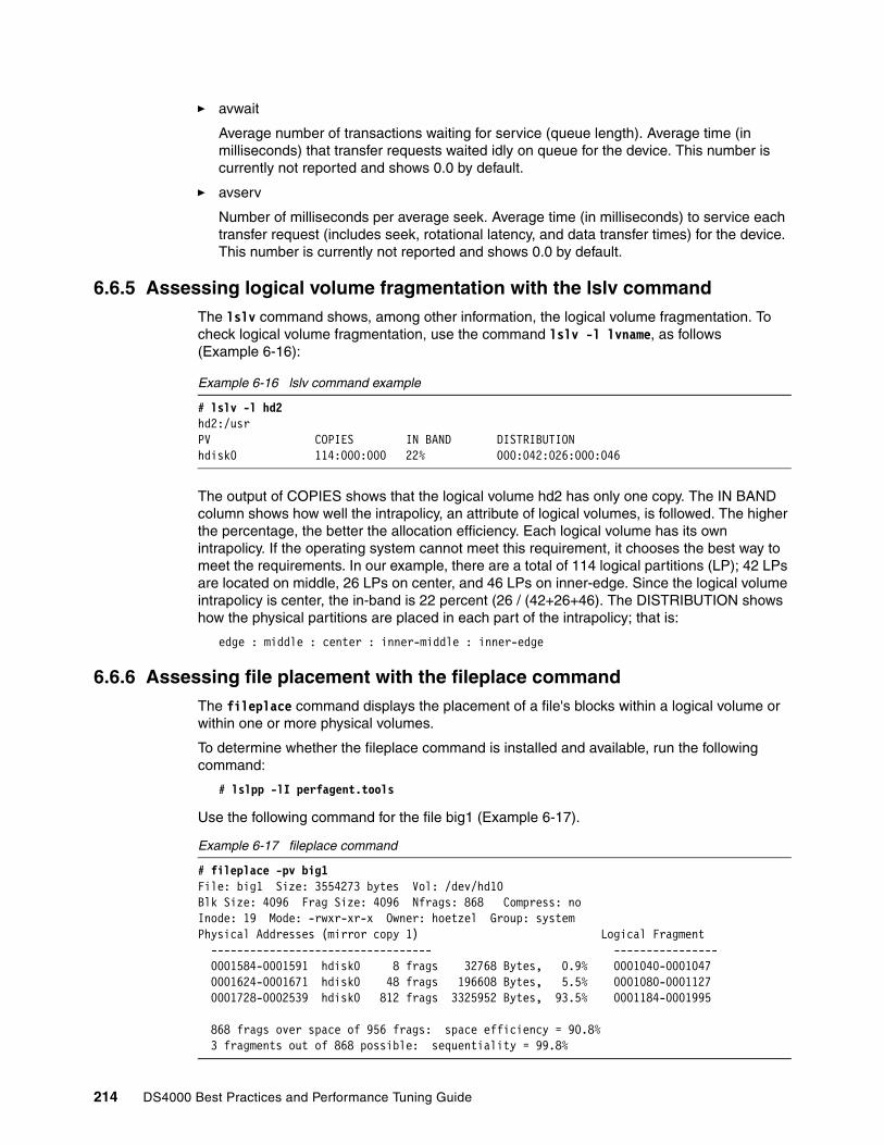
� avwait
Average number of transactions waiting for service (queue length). Average time (in milliseconds) that transfer requests waited idly on queue for the device. This number is currently not reported and shows 0.0 by default.
� avserv
Number of milliseconds per average seek. Average time (in milliseconds) to service each transfer request (includes seek, rotational latency, and data transfer times) for the device. This number is currently not reported and shows 0.0 by default.
6.6.5 Assessing logical volume fragmentation with the lslv commandThe lslv command shows, among other information, the logical volume fragmentation. To check logical volume fragmentation, use the command lslv -l lvname, as follows (Example 6-16):
Example 6-16 lslv command example
# lslv -l hd2hd2:/usrPV COPIES IN BAND DISTRIBUTIONhdisk0 114:000:000 22% 000:042:026:000:046
The output of COPIES shows that the logical volume hd2 has only one copy. The IN BAND column shows how well the intrapolicy, an attribute of logical volumes, is followed. The higher the percentage, the better the allocation efficiency. Each logical volume has its own intrapolicy. If the operating system cannot meet this requirement, it chooses the best way to meet the requirements. In our example, there are a total of 114 logical partitions (LP); 42 LPs are located on middle, 26 LPs on center, and 46 LPs on inner-edge. Since the logical volume intrapolicy is center, the in-band is 22 percent (26 / (42+26+46). The DISTRIBUTION shows how the physical partitions are placed in each part of the intrapolicy; that is:
edge : middle : center : inner-middle : inner-edge
6.6.6 Assessing file placement with the fileplace commandThe fileplace command displays the placement of a file's blocks within a logical volume or within one or more physical volumes.
To determine whether the fileplace command is installed and available, run the following command:
# lslpp -lI perfagent.tools
Use the following command for the file big1 (Example 6-17).
Example 6-17 fileplace command
# fileplace -pv big1File: big1 Size: 3554273 bytes Vol: /dev/hd10Blk Size: 4096 Frag Size: 4096 Nfrags: 868 Compress: noInode: 19 Mode: -rwxr-xr-x Owner: hoetzel Group: systemPhysical Addresses (mirror copy 1) Logical Fragment ---------------------------------- ---------------- 0001584-0001591 hdisk0 8 frags 32768 Bytes, 0.9% 0001040-0001047 0001624-0001671 hdisk0 48 frags 196608 Bytes, 5.5% 0001080-0001127 0001728-0002539 hdisk0 812 frags 3325952 Bytes, 93.5% 0001184-0001995 868 frags over space of 956 frags: space efficiency = 90.8% 3 fragments out of 868 possible: sequentiality = 99.8%
214 DS4000 Best Practices and Performance Tuning Guide

This example shows that there is very little fragmentation within the file, and those are small gaps. We can therefore infer that the disk arrangement of big1 is not significantly affecting its sequential read-time. Further, given that a (recently created) 3.5 MB file encounters so little fragmentation, it appears that the file system in general has not become particularly fragmented.
Occasionally, portions of a file may not be mapped to any blocks in the volume. These areas are implicitly filled with zeroes by the file system. These areas show as unallocated logical blocks. A file that has these holes will show the file size to be a larger number of bytes than it actually occupies (that is, the ls -l command will show a large size, whereas the du command will show a smaller size or the number of blocks the file really occupies on disk).
The fileplace command reads the file's list of blocks from the logical volume. If the file is new, the information may not be on disk yet. Use the sync command to flush the information. Also, the fileplace command will not display NFS remote files (unless the command runs on the server).
Space efficiency and sequentialityHigher space efficiency means files are less fragmented and probably provide better sequential file access. A higher sequentiality indicates that the files are more contiguously allocated, and this will probably be better for sequential file access.
� Space efficiency: Total number of fragments used for file storage (Largest fragment physical address - Smallest fragment physical address + 1)
� Sequentiality: Total number of fragments - Number of grouped fragments +1) / Total number of fragments
If you find that your sequentiality or space efficiency values become low, you can use the reorgvg command to improve logical volume utilization and efficiency
In Example 6-17, the Largest fragment physical address - Smallest fragment physical address + 1 is: 0002539 - 0001584 + 1 = 956 fragments; total used fragments is: 8 + 48 + 812 = 868; the space efficiency is 868 / 956 (90.8 percent); the sequentiality is (868 - 3 + 1) / 868 = 99.8 percent.
Because the total number of fragments used for file storage does not include the indirect blocks location, but the physical address does, the space efficiency can never be 100 percent for files larger than 32 KB, even if the file is located on contiguous fragments.
6.6.7 The topas commandThe topas command is a performance monitoring tool that is ideal for broad spectrum performance analysis. The command is capable of reporting on local system statistics such as CPU use, CPU events and queues, memory and paging use, disk performance, network performance, and NFS statistics. It can report on the top hot processes of the system as well as on Workload Manager (WLM) hot classes. The WLM class information is only displayed when WLM is active.
Note: If a file has been created by seeking to various locations and writing widely dispersed records, only the pages that contain records will take up space on disk and appear on a fileplace report. The file system does not fill in the intervening pages automatically when the file is created. However, if such a file is read sequentially (by the cp or tar commands, for example) the space between records is read as binary zeroes. Thus, the output of such a cp command can be much larger than the input file, although the data is the same.
Chapter 6. Analyzing and measuring performance 215

The topas command defines hot processes as those processes that use a large amount of CPU time. The topas command does not have an option for logging information. All information is real time.
The topas command requires the perfagent.tools fileset to be installed on the system. The topas command resides in /usr/bin and is part of the bos.perf.tools fileset that is obtained from the AIX base installable media.
The syntax of the topas command is as follows.
topas [ -d number_of_monitored_hot_disks ][ -h show help information ][ -i monitoring_interval_in_seconds ][ -n number_of_monitored_hot_network_interfaces][ -p number_of_monitored_hot_processes ][ -w number_of_monitored_hot_WLM classes ][ -c number_of_monitored_hot_CPUs ][ -P show full-screen process display ][ -W show full-screen WLM display ]
Where:
� -d
Specifies the number of disks to be displayed and monitored. The default value of two is used by the command if this value is omitted from the command line. In order that no disk information is displayed, the value of zero must be used. If the number of disks selected by this flag exceeds the number of physical disks in the system, then only the physically present disks will be displayed. Because of the limited space available, only the number of disks that fit into the display window are shown. The disks by default are listed in descending order of kilobytes read and written per second KBPS. This can be changed by moving the cursor to an alternate disk heading (for example, Busy%).
� -h
Used to display the topas help.
� -i
Sets the data collection interval and is given in seconds. The default value is two.
� -n
Used to set the number of network interfaces to be monitored. The default is two. The number of interfaces that can be displayed is determined by the available display area. No network interface information will be displayed if the value is set to zero.
� -p
Used to display the top hot processes on the system. The default value of 20 is used if the flag is omitted from the command line. To omit top process information from the displayed output, the value of this flag must be set to zero. If there is no requirement to determine the top hot processes on the system, then this flag should be set to zero, as this function is the main contributor of the total overhead of the topas command on the system.
Note: In order to obtain a meaningful output from the topas command, the screen or graphics window must support a minimum of 80 characters by 24 lines. If the display is smaller than this, then parts of the output become illegible.
216 DS4000 Best Practices and Performance Tuning Guide

� -w
Specifies the number of WLM classes to be monitored. The default value of two is assumed if this value is omitted. The classes are displayed as display space permits. If this value is set to zero, then no information about WLM classes will be displayed. Setting this flag to a value greater than the number of available WLM classes results in only the available classes being displayed.
� -P
Used to display the top hot processes on the system in greater detail than is displayed with the -p flag. Any of the columns can be used to determine the order of the list of processes. To change the order, simply move the cursor to the appropriate heading.
� -W
Splits the full screen display. The top half of the display shows the top hot WLM classes in detail, and the lower half of the screen displays the top hot processes of the top hot WLM class.
Information about measurement and samplingThe topas command makes use of the System Performance Measurement Interface (SPMI) Application Program Interface (API) for obtaining its information. By using the SPMI API, the system overhead is kept to a minimum. The topas command uses the perfstat library call to access the perfstat kernel extensions. In instances where the topas command determines values for system calls, CPU clicks, and context switches, the appropriate counter is incremented by the kernel, and the mean value is determined over the interval period set by the -i flag. Other values such as free memory are merely snapshots at the interval time. The sample interval can be selected by the user by using the -i flag option. If this flag is omitted in the command line, then the default of two seconds is used.
6.7 FAStT MSJIn this section we discuss IBM FAStT MSJ in the context of troubleshooting, and how to monitor Qlogic based host bus adapters.
The FAStT Management Suite Java GUI can be used to manage the host bus adapters in servers running the FAStT MSJ agent. This section gives an overview on how to use the tool to make changes to the configuration of host bus adapters, perform diagnostic tests, and check the performance of the host bus adapters.
Details can be obtained from the Web site:
http://www.ibm.com/servers/storage/support/disk
Then, search under the specific DS4000 model under TOOLS section.
For more information on FAStT MSJ, refer to the redbook, IBM TotalStorage DS4000 Series and Storage manager, SG24-7010.
6.7.1 Using the FAStT MSJ diagnostic toolsYou must first use the FAStT MSJ and connect to the server that contains the HBA that you wish to diagnose. When you click one of the host bus adapter ports in the HBA tree panel, the tab panel displays eight tabs as shown in Figure 6-40.
Chapter 6. Analyzing and measuring performance 217
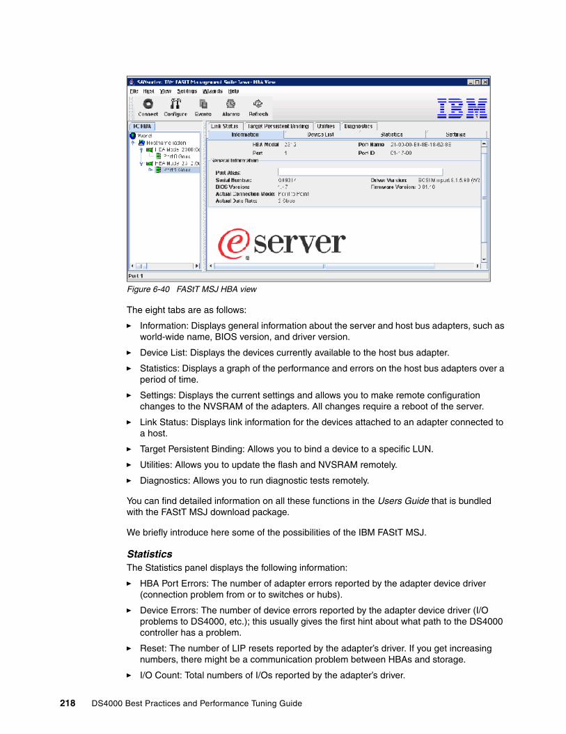
Figure 6-40 FAStT MSJ HBA view
The eight tabs are as follows:
� Information: Displays general information about the server and host bus adapters, such as world-wide name, BIOS version, and driver version.
� Device List: Displays the devices currently available to the host bus adapter.
� Statistics: Displays a graph of the performance and errors on the host bus adapters over a period of time.
� Settings: Displays the current settings and allows you to make remote configuration changes to the NVSRAM of the adapters. All changes require a reboot of the server.
� Link Status: Displays link information for the devices attached to an adapter connected to a host.
� Target Persistent Binding: Allows you to bind a device to a specific LUN.
� Utilities: Allows you to update the flash and NVSRAM remotely.
� Diagnostics: Allows you to run diagnostic tests remotely.
You can find detailed information on all these functions in the Users Guide that is bundled with the FAStT MSJ download package.
We briefly introduce here some of the possibilities of the IBM FAStT MSJ.
StatisticsThe Statistics panel displays the following information:
� HBA Port Errors: The number of adapter errors reported by the adapter device driver (connection problem from or to switches or hubs).
� Device Errors: The number of device errors reported by the adapter device driver (I/O problems to DS4000, etc.); this usually gives the first hint about what path to the DS4000 controller has a problem.
� Reset: The number of LIP resets reported by the adapter’s driver. If you get increasing numbers, there might be a communication problem between HBAs and storage.
� I/O Count: Total numbers of I/Os reported by the adapter’s driver.
218 DS4000 Best Practices and Performance Tuning Guide

� IOPS (I/O per second): The current number of I/Os processed by the adapter.
� BPS (bytes per second): The current numbers of bytes processed by the adapter.
The Statistics panel is shown in Figure 6-41.
Figure 6-41 Statistics Window in IBM FAStT MSJ
To get the graph working, you should select Auto Poll, then click Set Rate to set a suitable polling rate, and the graph will start to display statistics.
To keep the statistics, select Log to File. You will be prompted for a path to save the file. This will create a CSV file of the statistics.
Link StatusIf you experience problems with connectivity or performance, or you see entries from RDAC or the HBA driver in Windows, the Link Status tab is where you should start from, to narrow down the device causing the problems (faulty cable, SFPs, etc.).
The following information can be retrieved from the Link Status window:
� Link Failure: The number of times the link failed. A link failure is a possible cause for a time-out (see Windows Event Log).
� Loss of Sync: The number of times the adapter had to re-synchronize the link.
� Loss Signal: The number of times the signal was lost (dropped and re-connected).
� Invalid CRC: The number of Cyclic Redundancy Check (CRC) errors that were detected by the device.
Chapter 6. Analyzing and measuring performance 219

DiagnosticsUsing the Diagnostics panel you can perform the loopback and read/write buffer tests.
� The loopback test is internal to the adapter. The test evaluates the Fibre Channel loop stability and error rate. The test transmits and receives (loops back) the specified data and checks for frame CRC, disparity, and length errors.
� The read/write buffer test sends data through the SCSI Write Buffer command to a target device, reads the data back through the SCSI Read Buffer command, and compares the data for errors. The test also compares the link status of the device before and after the read/write buffer test. If errors occur, the test indicates a broken or unreliable link between the adapter and the device.
The Diagnostics panel has three main parts:
� Identifying Information: Displays information about the adapter being tested
� Test Configuration: Contains testing options (like data patterns, number of tests, test increments)
� Test Results: Displays the results of a test showing whether the test passed or failed and error counters
– For a loopback test, the test result includes the following information: Test Status, CRC Error, Disparity Error, and Frame Length Error.
– For a read/write buffer test, the test result shows the following information: ID (Port/Loop) Status, Data Miscompare, Link Failure, Sync Loss, Signal Loss, and Invalid CRC.
6.8 MPPUTIL Windows 2000/2003With the introduction of the new RDAC driver architecture in Windows 2000 and Windows 2003 a new command line utility, called mppUtil was introduced as well. Once you have installed the new RDAC driver, the utility can be found in C:\Program Files\IBM_DS4000\mpp\mppUtil.exe
With mppUtil, you can display the driver internal information like controller, path and volume information for a specified DS4000. It also allows you to rescan for new LUNs as well as doing a failback initiated from the host after a volume failover has occurred. This means that you no longer need to redistribute logical drives from the Storage Manager after failover, but you can simply use the mppUtil to move the volumes back to the preferred paths.
If you want to scan for all the DS4000s that are attached to your Windows 2000/2003 host you have to use the command mpputil -a as illustrated in Example 6-16.
Example 6-18 Using mpputil in Windows
C:\Program Files\IBM_DS4000\mpp\mpputil -aHostname = radonDomainname = almaden.ibm.comTime = GMT Fri Oct 21 21:23:49 2005
---------------------------------------------------------------Info of Array Module's seen by this Host.---------------------------------------------------------------ID WWN Name--------------------------------------------------------------- 0 600a0b80001744310000000041eff538 ITSODS4500_A---------------------------------------------------------------
220 DS4000 Best Practices and Performance Tuning Guide

If you want to get more details about a specific DS4000, you can either use the ID or the Name as parameter of the mppUtil command. Use the command mppUtil -a storage_server_name or mppUtil -g 0. Both will produce the same result.
6.9 Windows Performance MonitorWindows comes with a performance monitoring tool (don’t confuse it with the Storage Manager Performance Monitor). It can be run from the menu under Administrative tools → Performance or by entering perfmon at the command line. Performance logs and alerts can be used to get statistics from the operating system about the hardware.
You can configure Performance Monitor and alerts to display current performance statistics and also to log these statistics to a log file for later examination. In Windows Server 2003, these log files can be stored in text files, binary files, or an SQL database.
There is a vast array of counters that can be monitored, but monitoring does have a slight system overhead. The more counters being monitored, the higher the overhead and impact on performance.
In the case of the DS4000 storage server, a logical drive or LUN for the DS4000 is presented as a physical drive to the host operating system. This physical disk, as seen by the OS, can be then split up into several logical drives, depending on partitioning and formatting. With Performance Monitor, you can monitor the physical disk or the logical drives it contains.
The following disk counters are available:
� % Disk Read Time� % Disk Time� % Disk Write Time� % Idle Time� Average Disk Bytes/Read� Average Disk Bytes/Transfer� Average Disk Bytes/Write� Average Disk Queue Length� Average Disk Read Queue Length� Average Disk sec/Read� Average Disk sec/Transfer� Average Disk sec/Write� Average Disk Write Queue Length� Current Disk Queue Length� Disk Bytes/sec� Disk Read Bytes/sec� Disk Reads/sec� Disk Transfers/sec� Disk Write Bytes/sec� Disk Writes/sec� Split IO/sec
A list of all Logical Disk counters includes the list above, plus these two counters.
� % Free Space� Free Megabytes
Chapter 6. Analyzing and measuring performance 221

The counters to monitor for disk performance are:
Physical: Disk Reads/sec for the number of read requests per second to the disks.
Physical: Disk Writes/sec for the number of write requests per second to the disks.
Logical: % Free Space for the amount of free space left on a volume. This has a big impact on performance if the disk runs out of space.
Physical: Average Disk Queue Length that goes above 2 for a long period of time indicates that the disk is queuing requests continuously and that could indicate a potential bottleneck.
Physical: % Disk Time and % Idle Time. Interpret the % Disk Time counter carefully. This counter may not accurately reflect utilization on multiple disk system; it is important to use the % Idle Time counter as well. These counters cannot display a value exceeding 100%.
You may have to use these counters in conjunction with other counters (memory, network traffic, and processor utilization) to fully understand your Microsoft server and get a complete picture of the system performance.
Refer to your Microsoft documentation for a full explanation of these counters and how they are used to monitor system performance.
AlertsMicrosoft Performance logs and alerts can be configured to send an alert if the counters being monitored reach a preset threshold. This is a useful tool, but if the thresholds are set too low, false alerting may occur.
222 DS4000 Best Practices and Performance Tuning Guide

Chapter 7. DS4000 with AIX and HACMP
In this chapter, we present and discuss configuration information relevant to the DS4000 Storage Server attached to IBM Eserver pSeries and also review special considerations for High Availability Cluster Multiprocessing (HACMP) configurations in AIX.
AIX 5L™ is an award winning operating system, delivering superior scalability, reliability, and manageability. AIX 5L runs across the entire range of IBM pSeries systems, from entry-level servers and workstations to powerful supercomputers like the 64-way POWER5™ pSeries p595, able to handle the most complex commercial and technical workloads in the world. In addition, AIX has an excellent history of binary compatibility, which provides assurance that your critical applications will continue to run as you upgrade to newer versions of AIX 5L.
HACMP is the IBM software for building highly available clusters on a combination of pSeries systems. It is supported by a wide range of IBM Eserver pSeries systems, with the new storage systems, and network types, and it is one of the highest-rated, UNIX-based clustering solutions in the industry.
7
© Copyright IBM Corp. 2005, 2006. All rights reserved. 223
7.1 Configuring DS4000 in an AIX environmentIn this section we review the prerequisites and specifics for deploying the DS4000 storage server in an AIX host environment.
7.1.1 DS4000 adapters and drivers in an AIX environmentTo support the DS4000 Storage Server in an AIX environment, the IBM pSeries, RS/6000®, and RS/6000SP servers must be equipped with one of the following HBAs (see Table 7-1).
Table 7-1 HBAs for DS4000 and AIX
For detailed HBA information and to download the latest code levels, use the following link:
http://knowledge.storage.ibm.com/servers/storage/support/hbasearch/interop/hbaSearch.do
Verify microcode levelAlways make sure that the HBA is at a supported microcode level for the model and SM firmware version installed on your DS4000.
There are two methods to check the current microcode level on the adapter.
1. The first method uses the lscfg command. It returns much of the information in the adapter Vital Product data (VPD). The Z9 field contains the firmware level. This method also displays the FRU number and Assembly part number, and the World Wide Name WWn.
lscfg -vl fcsXWhere X is the number of the adapter returned by a previous lsdev command. The command will produce output similar to:
DEVICE LOCATION DESCRIPTION fcs1 P1-I1/Q1 FC AdapterPart Number.................80P4543FRU Number.................. 80P4544Network Address.............10000000C932A80ADevice Specific.(Z8)........20000000C932A80ADevice Specific.(Z9)........HS1.90A4
2. The second method uses the lsmcocde command. It returns the extension of the firmware image file that is installed. This method only works with the latest adapters.
lsmcocde -d fcsX
Where X is the number of the adapter returned by the lsdev command.
DISPLAY MICROCODE LEVEL 802111fcs3 FC AdapterThe current microcode level for fcs3 is 190104.Use Enter to continue.
Adapter Name AIX Operating system Cluster
IBM FC 5716 AIX 5.1 5.2 5.3 HACMP 5.1 5.2 5.3
IBM FC 6227 AIX 5.1 5.2 5.3 HACMP 5.1 5.2 5.3
IBM FC 6228 AIX 5.1 5.2 5.3 HACMP 5.1 5.2 5.3
IBM FC 6239 AIX 5.1 5.2 5.3 HACMP 5.1 5.2 5.3
224 DS4000 Best Practices and Performance Tuning Guide
Always check that you have the latest supported level of the firmware and drivers. If not, download the latest level and upgrade by following the instructions found at:
http://techsupport.services.ibm.com/server/mdownload/adapter.html
Install the RDAC driver on AIXYou need the following filesets for the AIX device driver:
� devices.fcp.disk.array.rte - RDAC runtime software� devices.fcp.disk.array.diag - RDAC diagnostic software� devices.common.IBM.fc.rte - Common FC Software
You also need one of the following drivers, depending on your HBA:
� devices.pci.df1000f7.com - Feature code for 6227 and 6228 adapters require this driver.� devices.pci.df1000f7.rte - Feature code 6227 adapter requires this driver.� devices.pci.df1000f9.rte - Feature code 6228 adapter requires this driver.� devices.pci.df1080f9.rte - Feature code 6239 adapter requires this driver.� devices.pci.df1000fa.rte - Feature code 5716 adapter requires this driver.
Additional packages or even PTFs might be required, depending on the level of your AIX operating system. Before installing the RDAC driver, always check prerequisites for a list of required driver version, filesets, level of AIX system.
pSeries/AIX Recommended OS Levels: AIX 5.1, 5.2 or 5.3 Multipath Driver: IBM AIX RDAC Driver (fcp.disk.array) and FC Protocol Device Drivers PTFs.
� AIX 5.3
Required Maintenance Level - 5300-3 devices.fcp.disk.array - 5.3.0.30 devices.pci.df1000f7.com - 5.3.0.10 devices.pci.df1000f7.rte - 5.3.0.30 devices.pci.df1000f9.rte - 5.3.0.30 devices.pci.df1000fa.rte - 5.3.0.30
� AIX 5.2
Required Maintenance Level - 5200-7 devices.fcp.disk.array - 5.2.0.75 devices.pci.df1000f7.com - 5.2.0.75 devices.pci.df1000f7.rte - 5.2.0.75 devices.pci.df1000f9.rte - 5.2.0.75 devices.pci.df1000fa.rte - 5.2.0.75
� AIX 5.1
Required Maintenance Level - 5100-9 devices.fcp.disk.array - 5.1.0.66 devices.pci.df1000f7.com - 5.1.0.66 devices.pci.df1000f7.rte - 5.1.0.37 devices.pci.df1000f9.rte - 5.1.0.37 devices.pci.df1000fa.rte - Not Supported
� AIX 4.3
Contains no support for features beyond Storage Manager 8.3.
AIX PTF/APARs can be downloaded from:
http://techsupport.services.ibm.com/server/aix.fdc
Chapter 7. DS4000 with AIX and HACMP 225

The RDAC driver creates the following devices that represent the DS4000 storage subsystem configuration:
� dar (disk array router): Represents the entire subsystem and storage partitions.
� dac (disk array controller devices): Represents a controller within the Storage Subsystem. There are two dacs in the Storage Subsystem.
� hdisk: These devices represent individual LUNs on the array.
� utm: The universal transport mechanism (utm) device is used only with in-band management configurations, as a communication channel between the SMagent and the DS4000 Storage Server.
DARFor a correct AIX host configuration, you should have DAR for every Storage Partition of every DS4000 connected to the AIX host (Example 7-1).
Example 7-1 Storage server, storage partitions and dar
One DS4000 with one Storage Partition dar0One DS4000 with two Storage Partition dar0,dar1Two DS4000 with two Storage Partition dar0,dar1,dar2,dar3
You can verify the number of DAR configured on the system by typing the command:
# lsdev -C | grep dar
DACFor a correct configuration, it is necessary to create an adequate zoning in such a way that every DAR shows two DACs assigned.
You can verify the number of DAC configured on the system by typing the command:
# lsdev -C | grep dac
Recreating the relationship between DAR and DACTo recreate the relationships, you must first remove the DAR, DAC, and HBA definitions from AIX. Proceed as follows:
Use the lsvg -o command to vary off all the volume groups attached to the HBA you want to remove (make sure there is no activity on DS4000 disks).
1. Remove DAR with the following command:
# rmdev -dl dar 0 -R
hdisk1 deletehdisk2 deletedar0 delete
2. Then, remove the HBA with the following command:
# rmdev -dl fcs1 -R
dac0 deletefscsi0 deletefcnet0 deletefcs0 delete
Attention: More than two DAC on each DAR is not supported (this would decrease the number of servers that you can connect to the DS4000 without additional benefit).
226 DS4000 Best Practices and Performance Tuning Guide
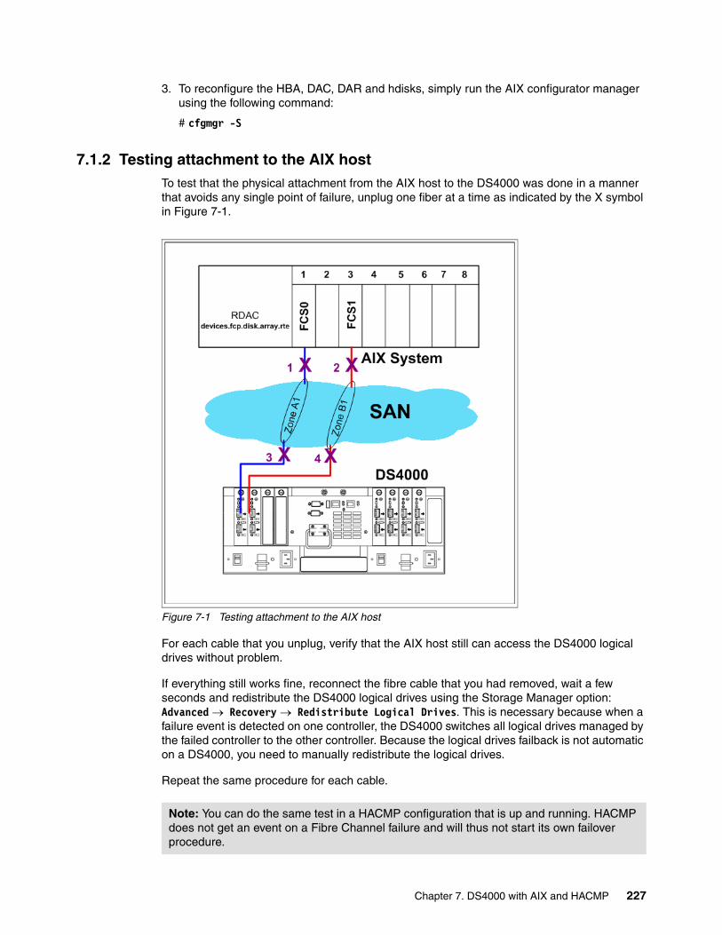
3. To reconfigure the HBA, DAC, DAR and hdisks, simply run the AIX configurator manager using the following command:
# cfgmgr -S
7.1.2 Testing attachment to the AIX hostTo test that the physical attachment from the AIX host to the DS4000 was done in a manner that avoids any single point of failure, unplug one fiber at a time as indicated by the X symbol in Figure 7-1.
Figure 7-1 Testing attachment to the AIX host
For each cable that you unplug, verify that the AIX host still can access the DS4000 logical drives without problem.
If everything still works fine, reconnect the fibre cable that you had removed, wait a few seconds and redistribute the DS4000 logical drives using the Storage Manager option: Advanced → Recovery → Redistribute Logical Drives. This is necessary because when a failure event is detected on one controller, the DS4000 switches all logical drives managed by the failed controller to the other controller. Because the logical drives failback is not automatic on a DS4000, you need to manually redistribute the logical drives.
Repeat the same procedure for each cable.
Note: You can do the same test in a HACMP configuration that is up and running. HACMP does not get an event on a Fibre Channel failure and will thus not start its own failover procedure.
Chapter 7. DS4000 with AIX and HACMP 227
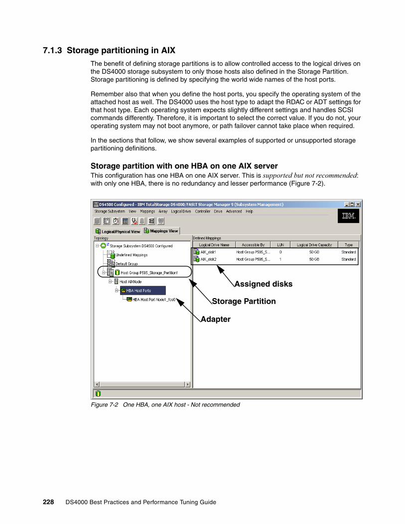
7.1.3 Storage partitioning in AIXThe benefit of defining storage partitions is to allow controlled access to the logical drives on the DS4000 storage subsystem to only those hosts also defined in the Storage Partition. Storage partitioning is defined by specifying the world wide names of the host ports.
Remember also that when you define the host ports, you specify the operating system of the attached host as well. The DS4000 uses the host type to adapt the RDAC or ADT settings for that host type. Each operating system expects slightly different settings and handles SCSI commands differently. Therefore, it is important to select the correct value. If you do not, your operating system may not boot anymore, or path failover cannot take place when required.
In the sections that follow, we show several examples of supported or unsupported storage partitioning definitions.
Storage partition with one HBA on one AIX serverThis configuration has one HBA on one AIX server. This is supported but not recommended: with only one HBA, there is no redundancy and lesser performance (Figure 7-2).
Figure 7-2 One HBA, one AIX host - Not recommended
Storage Partition
Adapter
Assigned disks
228 DS4000 Best Practices and Performance Tuning Guide

Storage partition mapping with two HBAs on one AIX serverThis is the most common situation. See Figure 7-3 for this configuration.
Figure 7-3 Two HBA, one AIX host
Two storage partitions with four HBAs on one AIX serverSee Figure 7-4 and Figure 7-5 for this configuration.
Figure 7-4 Two storage partitions - Two HBAs for each storage partition - First partition selected
Storage Partition
Adapters
Assigned disks
Storage Partition 1
Storage Partition 2
with two adapter and two disks
with two adapters
selected
Chapter 7. DS4000 with AIX and HACMP 229
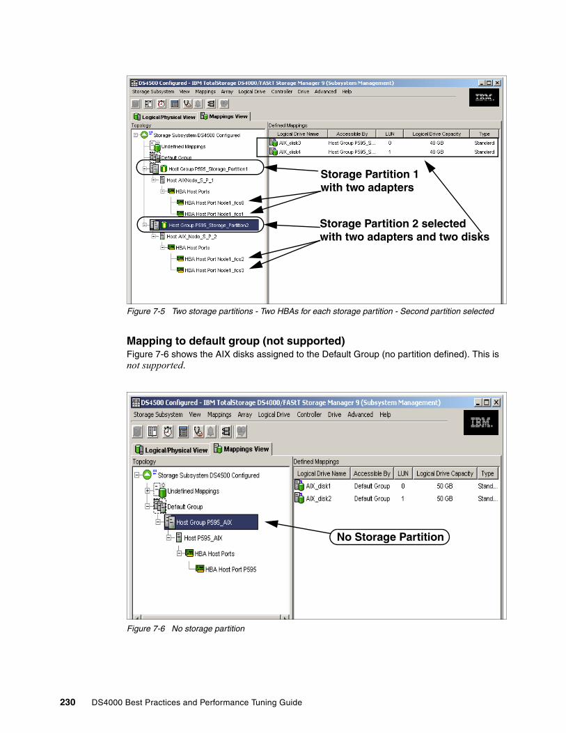
Figure 7-5 Two storage partitions - Two HBAs for each storage partition - Second partition selected
Mapping to default group (not supported)Figure 7-6 shows the AIX disks assigned to the Default Group (no partition defined). This is not supported.
Figure 7-6 No storage partition
Storage Partition 1
Storage Partition 2 selected
with two adapters
with two adapters and two disks
No Storage Partition
230 DS4000 Best Practices and Performance Tuning Guide
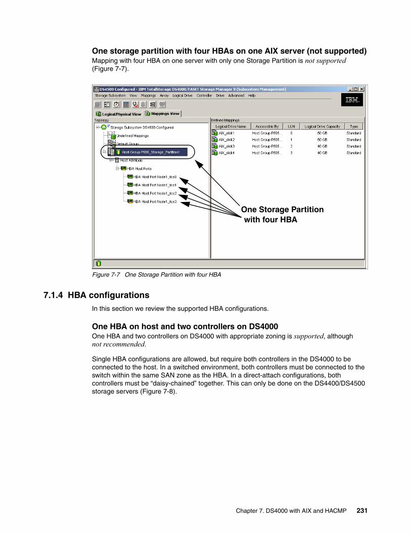
One storage partition with four HBAs on one AIX server (not supported)Mapping with four HBA on one server with only one Storage Partition is not supported (Figure 7-7).
Figure 7-7 One Storage Partition with four HBA
7.1.4 HBA configurationsIn this section we review the supported HBA configurations.
One HBA on host and two controllers on DS4000One HBA and two controllers on DS4000 with appropriate zoning is supported, although not recommended.
Single HBA configurations are allowed, but require both controllers in the DS4000 to be connected to the host. In a switched environment, both controllers must be connected to the switch within the same SAN zone as the HBA. In a direct-attach configurations, both controllers must be “daisy-chained” together. This can only be done on the DS4400/DS4500 storage servers (Figure 7-8).
One Storage Partitionwith four HBA
Chapter 7. DS4000 with AIX and HACMP 231
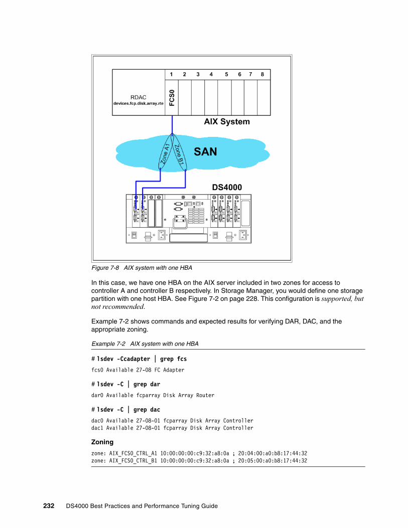
Figure 7-8 AIX system with one HBA
In this case, we have one HBA on the AIX server included in two zones for access to controller A and controller B respectively. In Storage Manager, you would define one storage partition with one host HBA. See Figure 7-2 on page 228. This configuration is supported, but not recommended.
Example 7-2 shows commands and expected results for verifying DAR, DAC, and the appropriate zoning.
Example 7-2 AIX system with one HBA
# lsdev -Ccadapter | grep fcs
fcs0 Available 27-08 FC Adapter
# lsdev -C | grep dar
dar0 Available fcparray Disk Array Router
# lsdev -C | grep dac
dac0 Available 27-08-01 fcparray Disk Array Controllerdac1 Available 27-08-01 fcparray Disk Array Controller
Zoning
zone: AIX_FCS0_CTRL_A1 10:00:00:00:c9:32:a8:0a ; 20:04:00:a0:b8:17:44:32zone: AIX_FCS0_CTRL_B1 10:00:00:00:c9:32:a8:0a ; 20:05:00:a0:b8:17:44:32
232 DS4000 Best Practices and Performance Tuning Guide
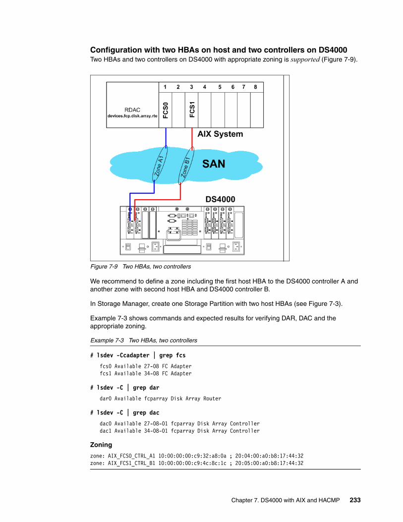
Configuration with two HBAs on host and two controllers on DS4000Two HBAs and two controllers on DS4000 with appropriate zoning is supported (Figure 7-9).
Figure 7-9 Two HBAs, two controllers
We recommend to define a zone including the first host HBA to the DS4000 controller A and another zone with second host HBA and DS4000 controller B.
In Storage Manager, create one Storage Partition with two host HBAs (see Figure 7-3).
Example 7-3 shows commands and expected results for verifying DAR, DAC and the appropriate zoning.
Example 7-3 Two HBAs, two controllers
# lsdev -Ccadapter | grep fcs
fcs0 Available 27-08 FC Adapterfcs1 Available 34-08 FC Adapter
# lsdev -C | grep dar
dar0 Available fcparray Disk Array Router
# lsdev -C | grep dac
dac0 Available 27-08-01 fcparray Disk Array Controllerdac1 Available 34-08-01 fcparray Disk Array Controller
Zoning
zone: AIX_FCS0_CTRL_A1 10:00:00:00:c9:32:a8:0a ; 20:04:00:a0:b8:17:44:32zone: AIX_FCS1_CTRL_B1 10:00:00:00:c9:4c:8c:1c ; 20:05:00:a0:b8:17:44:32
Chapter 7. DS4000 with AIX and HACMP 233
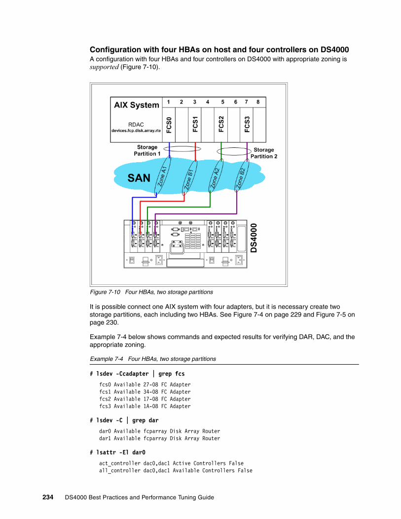
Configuration with four HBAs on host and four controllers on DS4000A configuration with four HBAs and four controllers on DS4000 with appropriate zoning is supported (Figure 7-10).
Figure 7-10 Four HBAs, two storage partitions
It is possible connect one AIX system with four adapters, but it is necessary create two storage partitions, each including two HBAs. See Figure 7-4 on page 229 and Figure 7-5 on page 230.
Example 7-4 below shows commands and expected results for verifying DAR, DAC, and the appropriate zoning.
Example 7-4 Four HBAs, two storage partitions
# lsdev -Ccadapter | grep fcs
fcs0 Available 27-08 FC Adapterfcs1 Available 34-08 FC Adapterfcs2 Available 17-08 FC Adapterfcs3 Available 1A-08 FC Adapter
# lsdev -C | grep dar
dar0 Available fcparray Disk Array Routerdar1 Available fcparray Disk Array Router
# lsattr -El dar0
act_controller dac0,dac1 Active Controllers Falseall_controller dac0,dac1 Available Controllers False
234 DS4000 Best Practices and Performance Tuning Guide
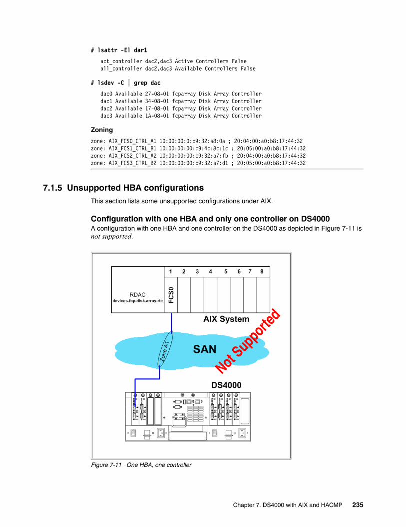
# lsattr -El dar1
act_controller dac2,dac3 Active Controllers Falseall_controller dac2,dac3 Available Controllers False
# lsdev -C | grep dac
dac0 Available 27-08-01 fcparray Disk Array Controllerdac1 Available 34-08-01 fcparray Disk Array Controllerdac2 Available 17-08-01 fcparray Disk Array Controllerdac3 Available 1A-08-01 fcparray Disk Array Controller
Zoning
zone: AIX_FCS0_CTRL_A1 10:00:00:0:c9:32:a8:0a ; 20:04:00:a0:b8:17:44:32zone: AIX_FCS1_CTRL_B1 10:00:00:00:c9:4c:8c:1c ; 20:05:00:a0:b8:17:44:32zone: AIX_FCS2_CTRL_A2 10:00:00:00:c9:32:a7:fb ; 20:04:00:a0:b8:17:44:32zone: AIX_FCS3_CTRL_B2 10:00:00:00:c9:32:a7:d1 ; 20:05:00:a0:b8:17:44:32
7.1.5 Unsupported HBA configurationsThis section lists some unsupported configurations under AIX.
Configuration with one HBA and only one controller on DS4000A configuration with one HBA and one controller on the DS4000 as depicted in Figure 7-11 is not supported.
Figure 7-11 One HBA, one controller
Not Supporte
d
Chapter 7. DS4000 with AIX and HACMP 235
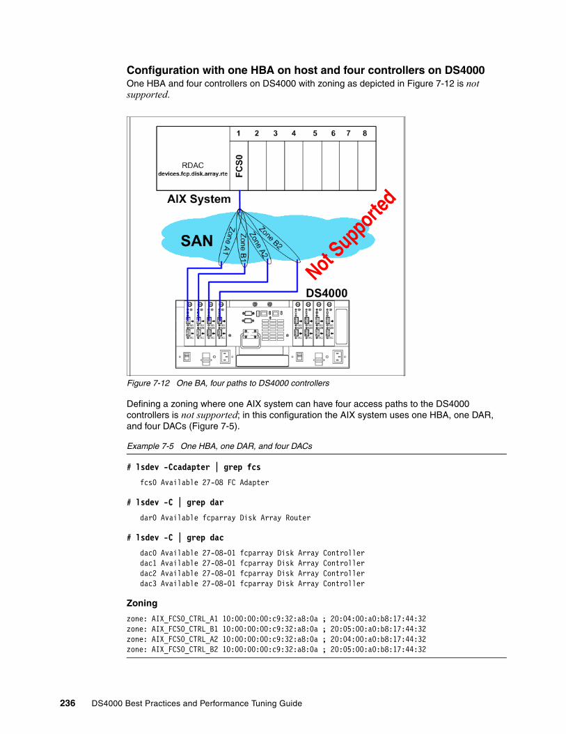
Configuration with one HBA on host and four controllers on DS4000One HBA and four controllers on DS4000 with zoning as depicted in Figure 7-12 is not supported.
Figure 7-12 One BA, four paths to DS4000 controllers
Defining a zoning where one AIX system can have four access paths to the DS4000 controllers is not supported; in this configuration the AIX system uses one HBA, one DAR, and four DACs (Figure 7-5).
Example 7-5 One HBA, one DAR, and four DACs
# lsdev -Ccadapter | grep fcs
fcs0 Available 27-08 FC Adapter
# lsdev -C | grep dar
dar0 Available fcparray Disk Array Router
# lsdev -C | grep dac
dac0 Available 27-08-01 fcparray Disk Array Controllerdac1 Available 27-08-01 fcparray Disk Array Controllerdac2 Available 27-08-01 fcparray Disk Array Controllerdac3 Available 27-08-01 fcparray Disk Array Controller
Zoning
zone: AIX_FCS0_CTRL_A1 10:00:00:00:c9:32:a8:0a ; 20:04:00:a0:b8:17:44:32zone: AIX_FCS0_CTRL_B1 10:00:00:00:c9:32:a8:0a ; 20:05:00:a0:b8:17:44:32zone: AIX_FCS0_CTRL_A2 10:00:00:00:c9:32:a8:0a ; 20:04:00:a0:b8:17:44:32zone: AIX_FCS0_CTRL_B2 10:00:00:00:c9:32:a8:0a ; 20:05:00:a0:b8:17:44:32
Not Supporte
d
236 DS4000 Best Practices and Performance Tuning Guide

Configuration with two HBA on host and four controller pathsTwo HBAs and four controller paths with the zoning as depicted in Figure 7-13 is not supported.
Figure 7-13 Two HBAs and four controller paths - Zoning 1
Configuration with two HBA on host and four controllers on DS4000Two HBAs and four controllers on DS4000 with the following zoning are not supported.
Figure 7-14 Two HBAs and four controller paths - Zoning 2
Not Supporte
d
Not Supporte
d
Chapter 7. DS4000 with AIX and HACMP 237

Configuration with four HBA and four controller pathsFour HBAs and four controllers on DS4000 with the zoning as depicted in Figure 7-15 are not supported.
Figure 7-15 Four HBA and Four controllers - Zoning 1
One AIX system with four HBAs connected to the DS4000 is not supported if each HBA sees more than one DS4000 controller.
Configuration with four HBA on node and four controllersFour HBAs and four controllers on DS4000 with this zoning are not supported (Figure 7-16).
Figure 7-16 Four HBA and Four controllers - Zoning 2
Not Supporte
d
Not Supporte
d
238 DS4000 Best Practices and Performance Tuning Guide
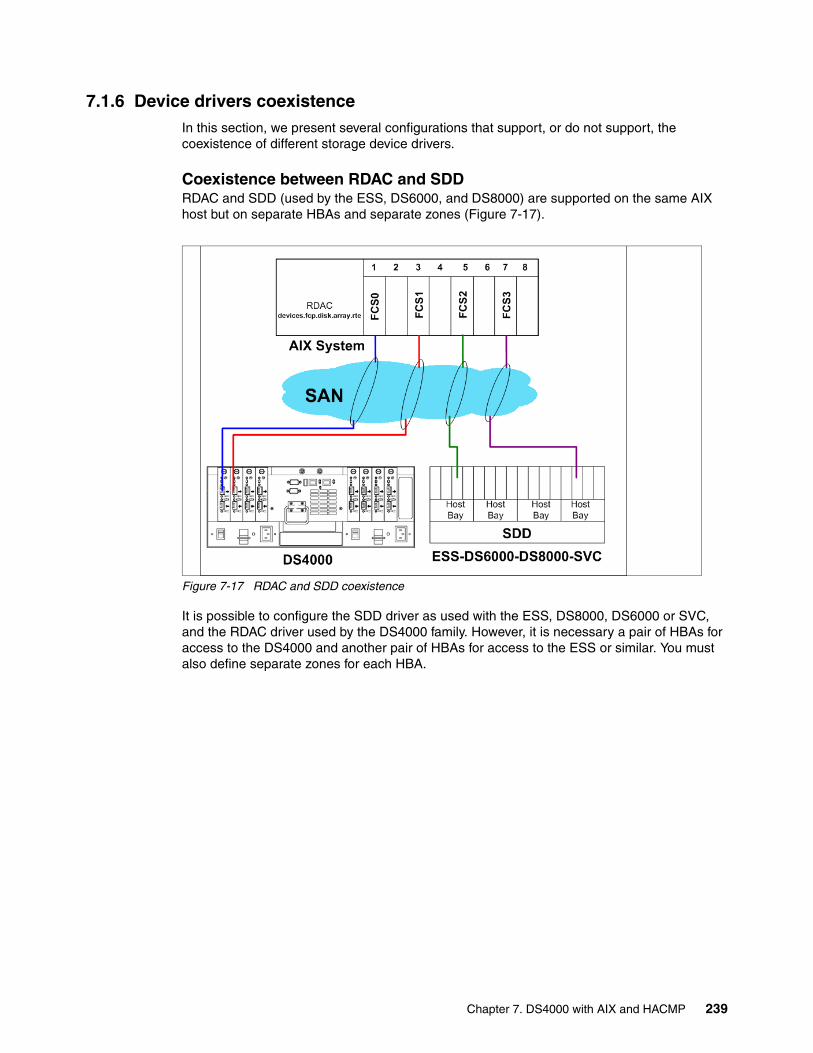
7.1.6 Device drivers coexistenceIn this section, we present several configurations that support, or do not support, the coexistence of different storage device drivers.
Coexistence between RDAC and SDDRDAC and SDD (used by the ESS, DS6000, and DS8000) are supported on the same AIX host but on separate HBAs and separate zones (Figure 7-17).
Figure 7-17 RDAC and SDD coexistence
It is possible to configure the SDD driver as used with the ESS, DS8000, DS6000 or SVC, and the RDAC driver used by the DS4000 family. However, it is necessary a pair of HBAs for access to the DS4000 and another pair of HBAs for access to the ESS or similar. You must also define separate zones for each HBA.
Chapter 7. DS4000 with AIX and HACMP 239

Therefore, the configuration with zoning as shown in Figure 7-18 is not supported.
Figure 7-18 RDAC and SDD unsupported zoning configuration
Coexistence between RDAC and TAPES Coexistence RDAC and tape devices is supported, but must have separate HBAs and separate zones (Figure 7-19).
Figure 7-19 Coexistence of DS4000 and Tape - Correct zoning
Not Supporte
d
240 DS4000 Best Practices and Performance Tuning Guide
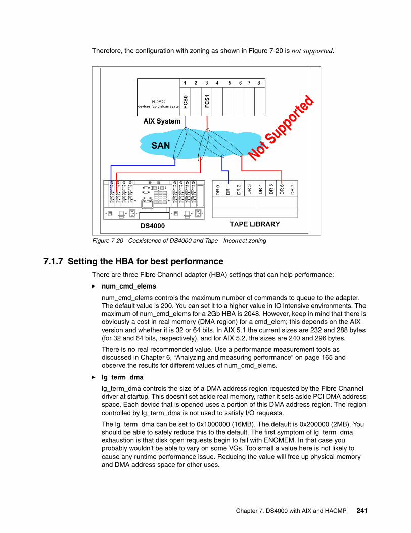
Therefore, the configuration with zoning as shown in Figure 7-20 is not supported.
Figure 7-20 Coexistence of DS4000 and Tape - Incorrect zoning
7.1.7 Setting the HBA for best performanceThere are three Fibre Channel adapter (HBA) settings that can help performance:
� num_cmd_elems
num_cmd_elems controls the maximum number of commands to queue to the adapter. The default value is 200. You can set it to a higher value in IO intensive environments. The maximum of num_cmd_elems for a 2Gb HBA is 2048. However, keep in mind that there is obviously a cost in real memory (DMA region) for a cmd_elem; this depends on the AIX version and whether it is 32 or 64 bits. In AIX 5.1 the current sizes are 232 and 288 bytes (for 32 and 64 bits, respectively), and for AIX 5.2, the sizes are 240 and 296 bytes.
There is no real recommended value. Use a performance measurement tools as discussed in Chapter 6, “Analyzing and measuring performance” on page 165 and observe the results for different values of num_cmd_elems.
� lg_term_dma
lg_term_dma controls the size of a DMA address region requested by the Fibre Channel driver at startup. This doesn't set aside real memory, rather it sets aside PCI DMA address space. Each device that is opened uses a portion of this DMA address region. The region controlled by lg_term_dma is not used to satisfy I/O requests.
The lg_term_dma can be set to 0x1000000 (16MB). The default is 0x200000 (2MB). You should be able to safely reduce this to the default. The first symptom of lg_term_dma exhaustion is that disk open requests begin to fail with ENOMEM. In that case you probably wouldn't be able to vary on some VGs. Too small a value here is not likely to cause any runtime performance issue. Reducing the value will free up physical memory and DMA address space for other uses.
Not Supporte
d
Chapter 7. DS4000 with AIX and HACMP 241

� max_xfer_size
This is the maximum IO size that the adapter will support. The default maximum transfer size is 0x100000. Consider changing this value to 200000 or larger.
Increasing this value increases the DMA memory area used for data transfer. You should resist the urge to just set these attributes to the maximums. There is a limit to the amount of DMA region available per slot and PCI bus. Setting these values too high may result in some adapters failing to configure because other adapters on the bus have already exhausted the resources. In the other hand, if too little space is set aside here, I/Os may be delayed in the FC adapter driver waiting for previous I/Os to finish. You will generally see errors in errpt if this happens.
For move details, see 6.4.3, “Using the Performance Monitor: Illustration” on page 188.
Viewing and changing HBA settings� To view possible attribute values of max_xfer_size for the fcs0 adapter, enter the
command:
lsattr -Rl fcs0 -a max_xfer_size
� The following command changes the maximum transfer size (max_xfer_size) and the maximum number of commands to queue (num_cmd_elems) of an HBA (fcs0) upon the next system reboot:
chdev -l fcs0 -P -a max_xfer_size=<value> -a num_cmd_elems=<value> -P
This will not take affect until after the system is rebooted.
� If you want to avoid a system reboot, make sure all activity is stopped on the adapter, and issue the following command:
chdev -l fcs0 -a max_xfer_size=<value> -a num_cmd_elems=<value>
Then recreate all child devices with the cfgmgr command.
7.1.8 DS4000 series – dynamic functionsWe know that the DS4000 offers several dynamic functions such as:
� DSS – Dynamic Segment Sizing� DRM – Dynamic RAID Migration� DCE – Dynamic Capacity Expansion� DVE – Dynamic Volume Expansion
These functions are supported AIX operating environments with some exceptions (for detailed information on supported platforms and operating systems, refer to the DS4000 compatibility matrix).
For Dynamic Volume Expansion:
� DVE support for AIX requires AIX 5.2 or later.� DVE for AIX 5.3 requires PTF U499974 installed before expanding any file systems.
In reality, in AIX there is no real Dynamic Volume Expansion because after increasing the size of the logical drive under the DS4000 Storage Manager, it is necessary, to use the additional disk space, to modify the volume group which contains that drive. A little downtime is required to perform the operation that is: stop the application, unmount all filesystems on this volume group and then varyoff the vg. At this point you need to change the characteristics of the volume group with chvg -g vgname, varyon the volume group, mount filesystems, and restart the application.
242 DS4000 Best Practices and Performance Tuning Guide

The detailed procedure is given in the section that follows.
Increase DS4000 LUN size in AIX step by step.This illustration assumes the following configuration:
� Two different logical drives (Kanaga_Lun0 and Kanaga_Lun1)in two separate RAID arrays on the DS4000.
� The logical drives are seen as two separate hdisk devices (hdisk3 and hdisk4) in AIX.
� In AIX LVM, we have defined one volume group (DS4000vg) with one logical volume (lvDS4000_1) striped on the two hdisks.
We show how to increase the size of the logical volume (lvDS4000-1), by increasing the size of hdisk3 and hdisk4 (thus without creating new disks).
Using the SMclient, we increase the size of the DS4000 logical drives by about 20 GB each (see Figure 7-21 and Figure 7-22).
Figure 7-21 Increase the size - Kanaga)_lun0
Figure 7-22 Increase the size - Kanaga_lun1
You can verify the size of the corresponding hdisk in AIX, by typing the following command:
# bootinfo -s hdisk3
Chapter 7. DS4000 with AIX and HACMP 243
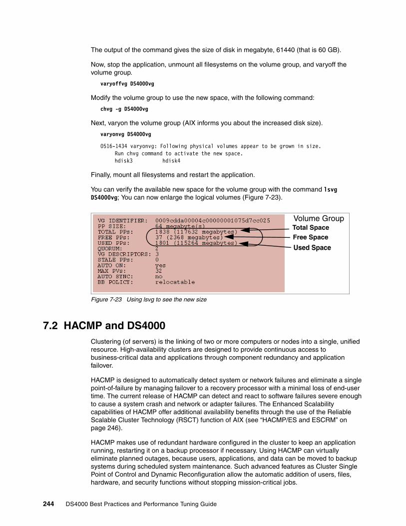
The output of the command gives the size of disk in megabyte, 61440 (that is 60 GB).
Now, stop the application, unmount all filesystems on the volume group, and varyoff the volume group.
varyoffvg DS4000vg
Modify the volume group to use the new space, with the following command:
chvg -g DS4000vg
Next, varyon the volume group (AIX informs you about the increased disk size).
varyonvg DS4000vg
0516-1434 varyonvg: Following physical volumes appear to be grown in size. Run chvg command to activate the new space. hdisk3 hdisk4
Finally, mount all filesystems and restart the application.
You can verify the available new space for the volume group with the command lsvg DS4000vg; You can now enlarge the logical volumes (Figure 7-23).
Figure 7-23 Using lsvg to see the new size
7.2 HACMP and DS4000Clustering (of servers) is the linking of two or more computers or nodes into a single, unified resource. High-availability clusters are designed to provide continuous access to business-critical data and applications through component redundancy and application failover.
HACMP is designed to automatically detect system or network failures and eliminate a single point-of-failure by managing failover to a recovery processor with a minimal loss of end-user time. The current release of HACMP can detect and react to software failures severe enough to cause a system crash and network or adapter failures. The Enhanced Scalability capabilities of HACMP offer additional availability benefits through the use of the Reliable Scalable Cluster Technology (RSCT) function of AIX (see “HACMP/ES and ESCRM” on page 246).
HACMP makes use of redundant hardware configured in the cluster to keep an application running, restarting it on a backup processor if necessary. Using HACMP can virtually eliminate planned outages, because users, applications, and data can be moved to backup systems during scheduled system maintenance. Such advanced features as Cluster Single Point of Control and Dynamic Reconfiguration allow the automatic addition of users, files, hardware, and security functions without stopping mission-critical jobs.
Volume Group Total SpaceFree Space
Used Space
244 DS4000 Best Practices and Performance Tuning Guide
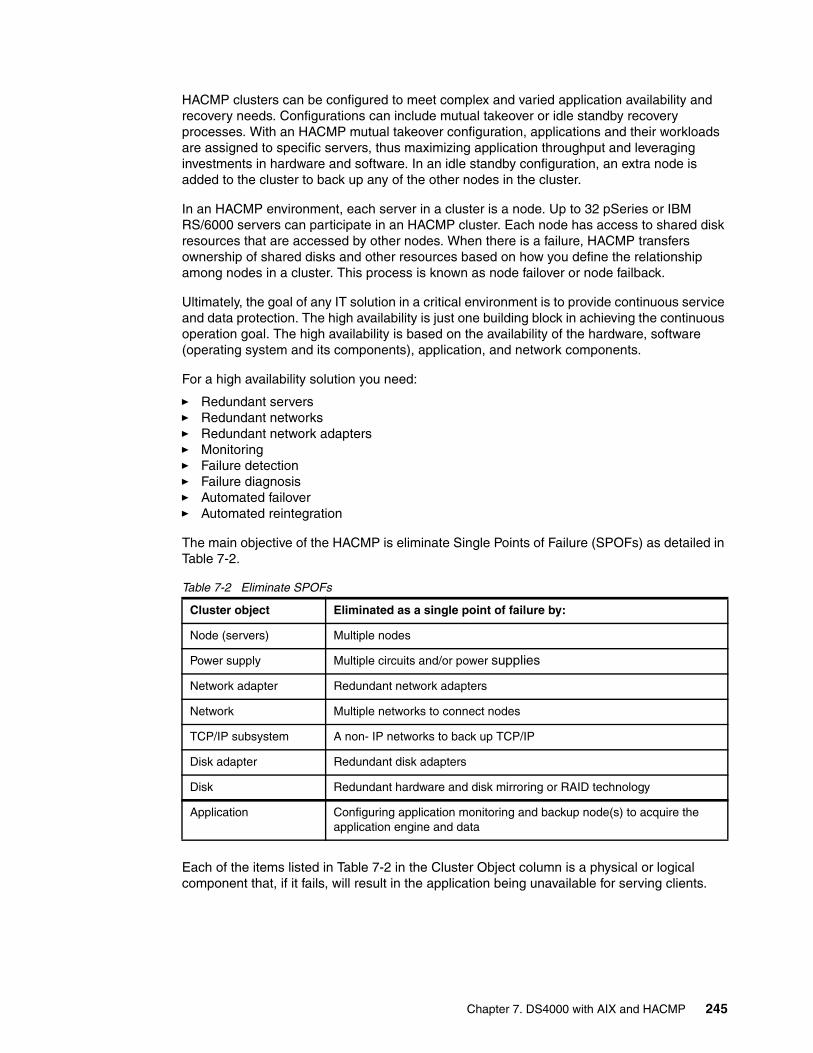
HACMP clusters can be configured to meet complex and varied application availability and recovery needs. Configurations can include mutual takeover or idle standby recovery processes. With an HACMP mutual takeover configuration, applications and their workloads are assigned to specific servers, thus maximizing application throughput and leveraging investments in hardware and software. In an idle standby configuration, an extra node is added to the cluster to back up any of the other nodes in the cluster.
In an HACMP environment, each server in a cluster is a node. Up to 32 pSeries or IBM RS/6000 servers can participate in an HACMP cluster. Each node has access to shared disk resources that are accessed by other nodes. When there is a failure, HACMP transfers ownership of shared disks and other resources based on how you define the relationship among nodes in a cluster. This process is known as node failover or node failback.
Ultimately, the goal of any IT solution in a critical environment is to provide continuous service and data protection. The high availability is just one building block in achieving the continuous operation goal. The high availability is based on the availability of the hardware, software (operating system and its components), application, and network components.
For a high availability solution you need:
� Redundant servers� Redundant networks� Redundant network adapters� Monitoring� Failure detection� Failure diagnosis� Automated failover� Automated reintegration
The main objective of the HACMP is eliminate Single Points of Failure (SPOFs) as detailed in Table 7-2.
Table 7-2 Eliminate SPOFs
Each of the items listed in Table 7-2 in the Cluster Object column is a physical or logical component that, if it fails, will result in the application being unavailable for serving clients.
Cluster object Eliminated as a single point of failure by:
Node (servers) Multiple nodes
Power supply Multiple circuits and/or power supplies
Network adapter Redundant network adapters
Network Multiple networks to connect nodes
TCP/IP subsystem A non- IP networks to back up TCP/IP
Disk adapter Redundant disk adapters
Disk Redundant hardware and disk mirroring or RAID technology
Application Configuring application monitoring and backup node(s) to acquire the application engine and data
Chapter 7. DS4000 with AIX and HACMP 245

The HACMP (High Availability Cluster Multi-Processing) software provides the framework and a set of tools for integrating applications in a highly available system. Applications to be integrated in a HACMP cluster require a fair amount of customization, not at the application level, but rather at the HACMP and AIX platform level. HACMP is a flexible platform that allows integration of generic applications running on AIX platform, providing for high available systems at a reasonable cost.
HACMP classicHigh Availability Subsystem (HAS) uses the global Object Data Manager (ODM) to store information about the cluster configuration and can have up to eight HACMP nodes in a HAS cluster. HAS provides the base services for cluster membership, system management, and configuration integrity. Control, failover, recovery, cluster status, and monitoring facilities are also there for programmers and system administrators.
The Concurrent Resource Manager (CRM) feature optionally adds the concurrent shared-access management for the supported RAID and SSA disk subsystem. Concurrent access is provided at the raw logical volume level, and the applications that use CRM must be able to control access to the shared data. The CRM includes the HAS, which provides a distributed locking facility to support access to shared data.
Before HACMP Version 4.4.0, if there was a need for a system to have high availability on a network file system (NFS), the system had to use high availability for the network file system (HANFS). HANFS Version 4.3.1 and earlier for AIX software provides a reliable NFS server capability by allowing a backup processor to recover current NFS activity should the primary NFS server fail. The HANFS for AIX software supports only two nodes in a cluster.
Since HACMP Version 4.4.0, the HANFS features are included in HACMP, and therefore, the HANFS is no longer a separate software product.
HACMP/ES and ESCRMScalability, support of large clusters, and therefore, large configurations of nodes and potentially disks leads to a requirement to manage “clusters” of nodes. To address management issues and take advantage of new disk attachment technologies, HACMP Enhanced Scalable (HACMP/ES) was released. This was originally only available for the SP where tools were already in place with PSSP to manage larger clusters.
ESCRM optionally adds concurrent shared-access management for the supported RAID and SSA disk subsystems. Concurrent access is provided at the raw disk level. The application must support some mechanism to control access to the shared data, such as locking. The ESCRM components includes the HACMP/ES components and the HACMP distributed lock manager.
7.2.1 Supported environment
For up-to-date information on the supported environments for DS4000, refer to:
http://www.ibm.com/servers/storage/disk/ds4000/ds4500/interop.html
For HACMP, refer to the following site:
http://www.ibm.com/servers/eserver/pseries/library/hacmp_doc.html
Important: Before installing DS4000 in an HACMP environment, always read the AIX readme file, the DS4000 readme for the specific Storage Manager version and model, and the HACMP configuration and compatibility matrix information.
246 DS4000 Best Practices and Performance Tuning Guide
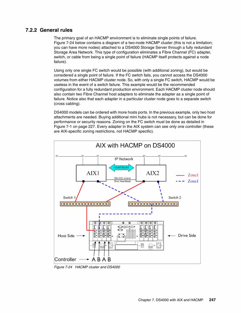
7.2.2 General rulesThe primary goal of an HACMP environment is to eliminate single points of failure. Figure 7-24 below contains a diagram of a two-node HACMP cluster (this is not a limitation; you can have more nodes) attached to a DS4000 Storage Server through a fully redundant Storage Area Network. This type of configuration eliminates a Fibre Channel (FC) adapter, switch, or cable from being a single point of failure (HACMP itself protects against a node failure).
Using only one single FC switch would be possible (with additional zoning), but would be considered a single point of failure. If the FC switch fails, you cannot access the DS4000 volumes from either HACMP cluster node. So, with only a single FC switch, HACMP would be useless in the event of a switch failure. This example would be the recommended configuration for a fully redundant production environment. Each HACMP cluster node should also contain two Fibre Channel host adapters to eliminate the adapter as a single point of failure. Notice also that each adapter in a particular cluster node goes to a separate switch (cross cabling).
DS4000 models can be ordered with more hosts ports. In the previous example, only two host attachments are needed. Buying additional mini hubs is not necessary, but can be done for performance or security reasons. Zoning on the FC switch must be done as detailed in Figure 7-1 on page 227. Every adapter in the AIX system can see only one controller (these are AIX-specific zoning restrictions, not HACMP specific).
Figure 7-24 HACMP cluster and DS4000
Chapter 7. DS4000 with AIX and HACMP 247

7.2.3 Configuration limitationsWhen installing a DS4000 in an HACMP environment, there are some restrictions and guidelines to take into account, which we list here. It does not mean that any other configuration will fail, but it could lead to unpredictable results, making it hard to manage and troubleshoot.
Applicable pSeries and AIX limitations (not HACMP specific)The following AIX and pSeries restrictions relevant in a HACMP environment apply to DS4100, DS4300, DS4400, DS4500, and DS4800 Storage Servers:
� A maximum of four HBAs per AIX host (or LPARs) can be connected to a single DS4000 storage server. You can configure up to two HBAs per partition and up to two partitions per DS4000 storage server. Additional HBAs can be added to support additional DS4000 storage servers and other SAN devices, up to the limits of your specific server platform.
� All volumes that are configured for AIX must be mapped to an AIX host group. Connecting and configuring to volumes in the default host group is not allowed.
� Other storage devices, such as tape devices or other disk storage, must be connected through separate HBAs and SAN zones.
� Each AIX host attaches to DS4000 Storage Servers using pairs of Fibre Channel adapters (HBAs):
– For each adapter pair, one HBA must be configured to connect to controller A, and the other to controller B.
– Each HBA pair must be configured to connect to a single partition in a DS4000 Storage Server or multiple DS4000 Storage Servers (fanout).
– To attach an AIX host to a single or multiple DS4000 with two partitions, two HBA pairs must be used.
� The maximum number of DS4000 partitions (host groups) per AIX host per DS4000 storage subsystem is two.
� Zoning must be implemented. If zoning is not implemented in a proper way, devices might appear on the hosts incorrectly. Follow these rules when implementing the zoning:
– Single-switch configurations are allowed, but each HBA and DS4000 controller combination must be in a separate SAN zone.
– Each HBA within a host must be configured in a separate zone from other HBAs within that same host when connected to the same DS4000 controller port. In other words, only one HBA within a host can be configured with a given DS4000 controller port in the same zone.
– Hosts within a cluster can share zones with each other.
– For highest availability, distributing the HBA and DS4000 connections across separate FC switches minimizes the effects of a SAN fabric failure.
General limitations and restrictions for HACMPKeep in mind the following general limitations and restrictions for HACMP:
� Only switched fabric connections are allowed between the host node and DS4000 — but no direct-attach connections.
� HACMP Cluster-Single Point of Control (C-SPOC) cannot be used to add a DS4000 disk to AIX through the “Add a Disk to the Cluster” facility.
� DS4000 subsystems with EXP100 disk enclosures are not supported in HACMP configurations at this time.
248 DS4000 Best Practices and Performance Tuning Guide
� Concurrent and Non-Concurrent modes are supported with HACMP Versions 5.1, 5.2, 5.3 and DS4000 running Storage Manager Versions 8.3 or later, including Hot Standby and Mutual Take-over.
� HACMP Versions 5.1, 5.2 and 5.3 are supported on the pSeries 690 LPAR and 590 LPAR clustered configurations.
� HACMP is now supported in Heterogeneous server environments. For more information regarding a particular operating system environment, refer to the specific Installation and Support Guide.
� HACMP clusters can support 2-32 servers for DS4000 partition. In this environment, be sure to read and understand the AIX device drivers queue depth settings, as documented in the IBM TotalStorage DS4000 Storage Manager Installation and Support Guide for AIX, UNIX, and Solaris, GC26-7574.
� Non-clustered AIX hosts can be connected to the same DS4000 that is attached to an HACMP cluster, but must be configured on separate DS4000 host partitions.
� Single HBA configurations are allowed, but each single HBA configuration requires that both controllers in the DS4000 be connected to a switch within the same SAN zone as the HBA. While single HBA configurations are supported, using a single HBA configuration is not recommended for HACMP environments, due to the fact that it introduces a single point of failure in the storage I/O path.
7.2.4 Planning considerationsWhen planning a high availability cluster, you should consider the sizing of the nodes, storage, network and so on, to provide the necessary resources for the applications to run properly, even in a takeover situation.
Sizing: choosing the nodes in the clusterBefore you start the implementation of the cluster, you should know how many nodes are required, and the type of the nodes that should be used. The type of nodes to be used is important in terms of the resources required by the applications.
Sizing of the nodes should cover the following aspects:
� CPU (number of CPUs and speed)� Amount of random access memory (RAM) in each node� Disk storage (internal)� Number of communication and disk adapters in each node� Node reliability
The number of nodes in the cluster depends on the number of applications to be made highly available, and also on the degree of availability desired. Having more than one spare node for each application in the cluster increases the overall availability of the applications.
HACMP V5.1, V5.2 and V5.3 support a variety of nodes, ranging from desktop systems to high-end servers. SP nodes and Logical Partitions (LPARs) are supported as well.
The cluster resource sharing is based on the applications requirements. Nodes that perform tasks that are not directly related to the applications to be made highly available and do not need to share resources with the application nodes should be configured in separate clusters for easier implementation and administration.
All nodes should provide sufficient resources (CPU, memory, and adapters) to sustain execution of all the designated applications in a fail-over situation (to take over the resources from a failing node).
Chapter 7. DS4000 with AIX and HACMP 249
We recommend using cluster nodes with a similar hardware configuration, especially when implementing clusters with applications in mutual takeover or concurrent configurations. This makes it easier to distribute resources and to perform administrative operations (software maintenance and so on).
Sizing: storage considerationsApplications to be made highly available require a shared storage space for application data. The shared storage space is used either for concurrent access, or for making the data available to the application on the takeover node (in a fail-over situation).
The storage to be used in a cluster should provide shared access from all designated nodes for each application. The technologies currently supported for HACMP shared storage are SCSI, SSA, and Fibre Channel — as is the case with the DS4000.
The storage configuration should be defined according to application requirements as non-shared (“private”) or shared storage. The private storage may reside on internal disks and is not involved in any takeover activity.
Shared storage should provide mechanisms for controlled access, considering the following reasons:
� Data placed in shared storage must be accessible from whichever node the application may be running at a point in time. In certain cases, the application is running on only one node at a time (non-concurrent), but in some cases, concurrent access to the data must be provided.
� In a non-concurrent environment, if the shared data is updated by the wrong node, this could result in data corruption.
� In a concurrent environment, the application should provide its own data access mechanism, since the storage controlled access mechanisms are by-passed by the platform concurrent software (AIX/HACMP).
7.2.5 Cluster disks setupThe following sections relate important information about cluster disk setup, and in particular describes cabling, AIX configuration, microcode loading, and configuration of DS4000 disks.
Figure 7-25 shows a simple two-node HACMP cluster and the basic cabling that we recommend. This configuration ensures redundancy and allows for possible future expansion and also could support remote mirroring because it leaves two available controllers on the DS4000.
250 DS4000 Best Practices and Performance Tuning Guide

Figure 7-25 HACMP - Recommended cabling and zoning
Logon to each of the AIX nodes in the cluster and verify that you have a working configuration. You should get an output similar to what is illustrated below for the various commands:
� Node1:
# lsdev -Ccadapterfcs0 Available 1Z-08 FC Adapterfcs1 Available 1D-08 FC Adapter
# lsdev -C | grep ^dardar0 Available 1742-900 (900) Disk Array Router
# lsdev -C | grep dacdac0 Available 1Z-08-02 1742-900 (900) Disk Array Controllerdac1 Available 1D-08-02 1742-900 (900) Disk Array Controller
� Node2:
# lsdev -Ccadapterfcs0 Available 1Z-08 FC Adapterfcs1 Available 1D-08 FC Adapter
# lsdev -C | grep ^dardar0 Available 1742-900 (900) Disk Array Router
# lsdev -C | grep dacdac0 Available 1Z-08-02 1742-900 (900) Disk Array Controllerdac1 Available 1D-08-02 1742-900 (900) Disk Array Controller
Chapter 7. DS4000 with AIX and HACMP 251
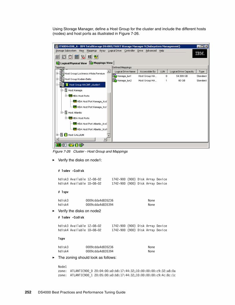
Using Storage Manager, define a Host Group for the cluster and include the different hosts (nodes) and host ports as illustrated in Figure 7-26.
Figure 7-26 Cluster - Host Group and Mappings
� Verify the disks on node1:
# lsdev -Ccdisk
hdisk3 Available 1Z-08-02 1742-900 (900) Disk Array Devicehdisk4 Available 1D-08-02 1742-900 (900) Disk Array Device
# lspv
hdisk3 0009cdda4d835236 Nonehdisk4 0009cdda4d835394 None
� Verify the disks on node2
# lsdev -Ccdisk
hdisk3 Available 1Z-08-02 1742-900 (900) Disk Array Devicehdisk4 Available 1D-08-02 1742-900 (900) Disk Array Device
lspv
hdisk3 0009cdda4d835236 Nonehdisk4 0009cdda4d835394 None
� The zoning should look as follows:
Node1zone: ATLANTIC900_0 20:04:00:a0:b8:17:44:32;10:00:00:00:c9:32:a8:0azone: ATLANTIC900_1 20:05:00:a0:b8:17:44:32;10:00:00:00:c9:4c:8c:1c
252 DS4000 Best Practices and Performance Tuning Guide

Node2zone: KANAGAF900_0 20:04:00:a0:b8:17:44:32;10:00:00:00:c9:32:a7:fbzone: KANAGAF900_1 20:05:00:a0:b8:17:44:32;10:00:00:00:c9:32:a7:d1
7.2.6 Shared LVM component configurationThis section describes how to define the LVM components shared by cluster nodes in an HACMP for AIX cluster environment.
Creating the volume groups, logical volumes, and file systems shared by the nodes in an HACMP cluster requires that you perform steps on all nodes in the cluster. In general, you define the components on one node (source node) and then import the volume group on the other nodes in the cluster (destination nodes). This ensures that the ODM definitions of the shared components are the same on all nodes in the cluster.
Non-concurrent access environments typically use journaled file systems to manage data, while concurrent access environments use raw logical volumes. This chapter provides different instructions for defining shared LVM components in non-concurrent access and concurrent access environments.
Creating shared VGThe following sections contain information about creating non-concurrent VGs and VGs for concurrent access.
Creating non-concurrent VGUse the smit mkvg fast path to create a shared volume group. Use the default field values unless your site has other requirements. See Table 7-3 for the smit mkvg options.
Table 7-3 smit mkvg options
Options Description
VOLUME GROUP name The name of the shared volume group should be unique within the cluster.
Physical partition SIZE in megabytes
Accept the default.
PHYSICAL VOLUME NAMES Specify the names of the physical volumes you want included in the volume group.
Activate volume group AUTOMATICALLY at system restart?
Set to no so that the volume group can be activated as appropriate by the cluster event scripts.
Volume Group MAJOR NUMBER If you are not using NFS, you can use the default (which is the next available number in the valid range). If you are using NFS, you must make sure to use the same major number on all nodes. Use the lvlstmajor command on each node to determine a free major number common to all nodes.
Create VG concurrent capable? Set this field to no (leave default)
Auto-varyon concurrent mode? Accept the default.
Chapter 7. DS4000 with AIX and HACMP 253

Creating VG for concurrent accessThe procedure used to create a concurrent access volume group varies, depending on which type of device you are using. In our case we will assume DS4000 disks.
To use a concurrent access volume group, defined on a DS4000 disk subsystem, you must create it as a concurrent-capable volume group. A concurrent-capable volume group can be activated (varied on) in either non-concurrent mode or concurrent access mode.
To define logical volumes on a concurrent-capable volume group, it must be varied on in non-concurrent mode.
Use smit mkvg with the options shown in Table 7-4 to build the volume group.
Table 7-4 Options for volumn group
Creating shared LV and file systemsUse the smit crjfs fast path to create the shared file system on the source node. When you create a journaled file system, AIX creates the corresponding logical volume. Therefore, you do not need to define a logical volume. You do, however, need to later rename both the logical volume and the log logical volume for the file system and volume group (Table 7-5).
Table 7-5 smit crjfs options
Options Description
VOLUME GROUP name The name of the shared volume group should be unique within the cluster.
Physical partition SIZE in megabytes Accept the default.
PHYSICAL VOLUME NAMES Specify the names of the physical volumes you want included in the volume group.
Activate volume group AUTOMATICALLY at system restart?
Set this field to no so that the volume group can be activated, as appropriate, by the cluster event scripts.
Volume Group MAJOR NUMBER While it is only really required when you are using NFS, it is always good practice in an HACMP cluster to have a shared volume group have the same major number on all the nodes that serve it. Use the lvlstmajor command on each node to determine a free major number common to all nodes.
Create VG concurrent capable? Set this field to yes so that the volume group can be activated in concurrent access mode by the HACMP for AIX event scripts
Auto-varyon concurrent mode? Set this field to no so that the volume group can be activated, as appropriate, by the cluster event scripts.
Options Description
Mount AUTOMATICALLY at system restart? Make sure this field is set to no.
Start Disk Accounting Make sure this field is set to no.
254 DS4000 Best Practices and Performance Tuning Guide
Renaming a jfslog and logical volumes on the source nodeAIX assigns a logical volume name to each logical volume it creates. Examples of logical volume names are /dev/lv00 and /dev/lv01. Within an HACMP cluster, the name of any shared logical volume must be unique. Also, the journaled file system log (jfslog) is a logical volume that requires a unique name in the cluster.
To make sure that logical volumes have unique names, rename the logical volume associated with the file system and the corresponding jfslog logical volume. Use a naming scheme that indicates the logical volume is associated with a certain file system. For example, lvsharefs could name a logical volume for the /sharefs file system. Follow these steps to rename the logical volumes:
1. Use the lsvg -l volume_group_name command to determine the name of the logical volume and the log logical volume (jfslog) associated with the shared volume groups. In the resulting display, look for the logical volume name that has type jfs. This is the logical volume. Then look for the logical volume name that has type jfslog. This is the log logical volume.
2. Use the smit chlv fast path to rename the logical volume and the log logical volume.
3. After renaming the jfslog or a logical volume, check the /etc/filesystems file to make sure the dev and log attributes reflect the change. Check the log attribute for each file system in the volume group, and make sure that it has the new jfslog name. Check the dev attribute for the logical volume that you renamed, and make sure that it has the new logical volume name.
Importing to other nodesThe following sections cover varying off a volume group on the source node, importing it onto the destination node, changing its startup status, and varying it off on the destination nodes.
Varying off a volume group on the source nodeUse the varyoffvg command to deactivate the shared volume group. You vary off the volume group so that it can be properly imported onto a destination node and activated as appropriate by the cluster event scripts. Enter the following command:
varyoffvg volume_group_name
Make sure that all the file systems of the volume group have been unmounted; otherwise, the varyoffvg command will not work.
Importing a volume group onto the destination nodeTo import a volume group onto destination nodes you can use the SMIT interface or the TaskGuide utility. The TaskGuide uses a graphical interface to guide you through the steps of adding nodes to an existing volume group. Importing the volume group onto the destination nodes synchronizes the ODM definition of the volume group on each node on which it is imported.
Chapter 7. DS4000 with AIX and HACMP 255

You can use the smit importvg fast path to import the volume group (Table 7-7).
Table 7-6 smit importvg options
Changing a volume group startup statusBy default, a volume group that has just been imported is configured to automatically become active at system restart. In an HACMP for AIX environment, a volume group should be varied on as appropriate by the cluster event scripts. Therefore, after importing a volume group, use the SMIT Change a Volume Group screen to reconfigure the volume group so that it is not activated automatically at system restart.
Use the smit chvg fast path to change the characteristics of a volume group (Table 7-7).
Table 7-7 smit chvg options
Varying off the volume group on the destination nodesUse the varyoffvg command to deactivate the shared volume group so that it can be imported onto another destination node or activated as appropriate by the cluster event scripts. Enter:
# varyoffvg volume_group_name
7.2.7 Fast disk takeoverBy utilizing the Enhanced Concurrent Mode volume groups, in non-concurrent resource groups, it almost eliminates disk takeover time by removing the need for disk reserves, and breaking these reserves. The volume groups are varied online in Active mode on only the owning node, and all other fall over candidate nodes have it varied on in Passive mode. RSCT is utilized for communications to coordinate activity between the nodes so that only one node has it varied on actively.
Time for disk takeover now is fairly consistent at around 10 seconds. Now with multiple resource groups and hundreds to thousands of disks, it may be a little more — but not significantly more.
Options Description
VOLUME GROUP name Enter the name of the volume group that you are importing. Make sure the volume group name is the same name that you used on the source node.
PHYSICAL VOLUME name Enter the name of a physical volume that resides in the volume group. Note that a disk may have a different logical name on different nodes. Make sure that you use the disk name as it is defined on the destination node.
Volume Group MAJOR NUMBER If you are not using NFS, you may use the default (which is the next available number in the valid range). If you are using NFS, you must make sure to use the same major number on all nodes. Use the lvlstmajor command on each node to determine a free major number common to all nodes.
Options Description
Activate volume group automatically at system restart?
Set this field to no.
A QUORUM of disks required to keep the volume group online?
If you are using DS4000 with raid protection set this field to no.
256 DS4000 Best Practices and Performance Tuning Guide
Note that while the VGs are varied on concurrently to both nodes, lsvg -o will only show the VG as active on the node accessing the disk; however, running lspv will show that the VG disks are active on both nodes. Also note, that lsvg vgname will tell you if the VG is in the active or passive state.
7.2.8 Forced varyon of volume groupsFor situations in which one is using LVM mirroring, and would like to survive failure of half the disks, there is a new attribute in the Resource Group smit panel to force varyon of the VG, provided that a complete copy of the LVs are available. Previously, this was accomplished by setting the HACMP_MIRROR_VARYON environment variable to yes, or via user written pre/post/recovery event scripts.
The new attribute in the Resource Group Smit panel is as follows:
Volume Groups Use forced varyon of volume groups, if necessary [false]
To take advantage of this feature, set this attribute to true, as the default is false.
7.2.9 Heartbeat over disksThis provides the ability to use existing shared disks, regardless of disk type, to provide serial network type connectivity. This can replace needs of using integrated serial ports and/or 8-port async adapters and the additional cables needed for it.
This feature utilizes a special reserve area, previously used by SSA Concurrent volume groups. Since Enhanced Concurrent does not use this space, it makes it available for use. This also means that the disk chosen for serial heartbeat can be, and probably will normally be, part of a data volume group.
The disk heartbeating code went into the 2.2.1.30 version of RSCT. Some recommended APARs bring that to 2.2.1.31. If you've got that level installed, and HACMP 5.1, you can use disk heartbeating. The relevant file to look for is /usr/sbin/rsct/bin/hats_diskhb_nim. Though it is supported mainly through RSCT, we recommend AIX 5.2 when utilizing disk heartbeat.
In HACMP 5.1 with AIX 5.1, enhanced concurrent mode volume groups can be used only in concurrent (or “online on all available nodes”) resource groups. At AIX 5.2, disk heartbeats can exist on an enhanced concurrent VG that resides in a non-concurrent resource group.
To use disk heartbeats, no node can issue a SCSI reserve for the disk. This is because both nodes using it for heartbeating must be able to read and write to that disk. It is sufficient that the disk be in an enhanced concurrent volume group to meet this requirement.
Creating a disk heartbeat device in HACMP v5.1 or upThis example consists of a two-node cluster (nodes Atlantic and Kanaga) with shared DS4000 disk devices. If more than two nodes exist in your cluster, you will need N number of non-IP heartbeat networks, where N represents the number of nodes in the cluster. (that is, a three node cluster requires three non-IP heartbeat networks). This creates a heartbeat ring (Figure 7-27).
Chapter 7. DS4000 with AIX and HACMP 257
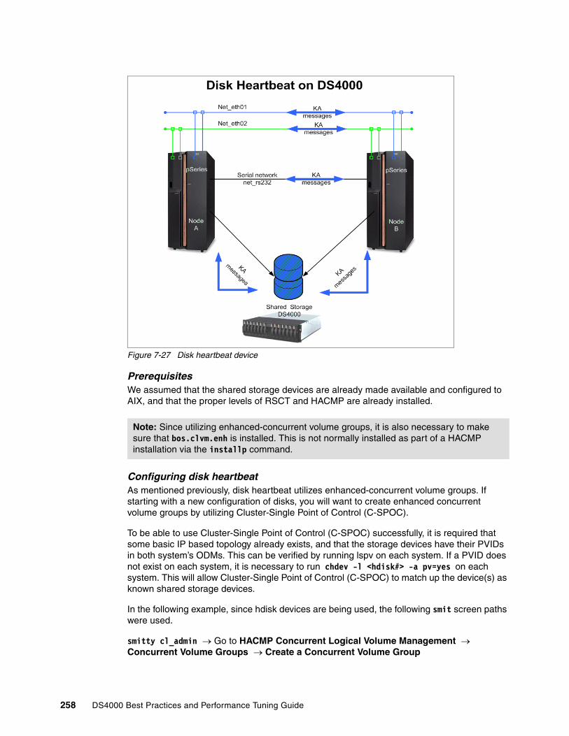
Figure 7-27 Disk heartbeat device
PrerequisitesWe assumed that the shared storage devices are already made available and configured to AIX, and that the proper levels of RSCT and HACMP are already installed.
Configuring disk heartbeatAs mentioned previously, disk heartbeat utilizes enhanced-concurrent volume groups. If starting with a new configuration of disks, you will want to create enhanced concurrent volume groups by utilizing Cluster-Single Point of Control (C-SPOC).
To be able to use Cluster-Single Point of Control (C-SPOC) successfully, it is required that some basic IP based topology already exists, and that the storage devices have their PVIDs in both system’s ODMs. This can be verified by running lspv on each system. If a PVID does not exist on each system, it is necessary to run chdev -l <hdisk#> -a pv=yes on each system. This will allow Cluster-Single Point of Control (C-SPOC) to match up the device(s) as known shared storage devices.
In the following example, since hdisk devices are being used, the following smit screen paths were used.
smitty cl_admin → Go to HACMP Concurrent Logical Volume Management → Concurrent Volume Groups → Create a Concurrent Volume Group
Note: Since utilizing enhanced-concurrent volume groups, it is also necessary to make sure that bos.clvm.enh is installed. This is not normally installed as part of a HACMP installation via the installp command.
258 DS4000 Best Practices and Performance Tuning Guide

Choose the appropriate nodes, and then choose the appropriate shared storage devices based on pvids (hdiskx). Choose a name for the VG, desired PP size, make sure that Enhanced Concurrent Mode is set to true and press Enter. This will create the shared enhanced-concurrent vg needed for our disk heartbeat.
On node1 Atlantic:
# lspv
hdisk7 000a7f5af78e0cf4 hacmp_hb_vg
On node2 Kanaga:
# lspv
hdisk3 000a7f5af78e0cf4 hacmp_hb_vg
Creating disk heartbeat devices and networkThere are two different ways to do this. Since we have already created the enhanced concurrent vg, we can use the discovery method (1) and let HA find it for us. Or we can do this manually via the Pre-defined devices method (2). Following is an example of each.
1. Creating via Discover Method:
Enter smitty hacmp → Extended Configuration → Discover HACMP-related Information from Configured Nodes
This will run automatically and create a clip_config file that contains the information it has discovered. Once completed, go back to the Extended Configuration menu and choose:
Extended Topology Configuration → Configure HACMP Communication Interfaces/Devices → Add Communication Interfaces/Devices → Add Discovered Communication Interface and Devices → Communication Devices → Choose appropriate devices (ex. hdisk3 and hdisk7)
– Select Point-to-Point Pair of Discovered Communication Devices to Add.
– Move the cursor to the desired item and press F7. Use arrow keys to scroll.
– ONE OR MORE items can be selected.
– Press Enter AFTER making all selections.
# Node Device Pvid> nodeAtlantic hdisk7 000a7f5af78> nodeKanaka hdisk3 000a7f5af78
2. Creating vie Pre-Defined Devices Method
When using this method, it is necessary to create a diskhb network first, then assign the disk-node pair devices to the network. Create the diskhb network as follows:
Enter smitty hacmp → Extended Configuration → Extended Topology Configuration → Configure HACMP Networks → Add a Network to the HACMP cluster →
Choose diskhb.
Attention: It is a good idea to verify via lspv once this has completed to make sure the device and VG is shown appropriately.
Chapter 7. DS4000 with AIX and HACMP 259
Enter desired network name (ex. disknet1) and press Enter:
smitty hacmp → Extended Configuration → Extended Topology Configuration → Configure HACMP Communication Interfaces/Devices → Add Communication Interfaces/Devices → Add Pre-Defined Communication Interfaces and Devices →
– Communication Devices → Choose your diskhb Network Name →
– Add a Communication Device
– Type or select values in entry fields.
– Press Enter AFTER making all desired changes:
Device Name [Atalantic_hboverdisk] Network Type diskhb Network Name disknet1 Device Path [/dev/hdisk7] Node Name [Atlantic]
For Device Name, that is a unique name you can chose. It will show up in your topology under this name, much like serial heartbeat and ttys have in the past.
For the Device Path, you want to put in /dev/<device name>. Then choose the corresponding node for this device and device name (ex. Atlantic). Then press Enter.
You will repeat this process for the other node (for example, Kanaga) and the other device (hdisk3). This will complete both devices for the diskhb network.
Testing disk heartbeat connectivityOnce the device and network definitions have been created, test the system and make sure communications are working properly. (If the volume group is varied on in normal mode on one of the nodes, the test will probably not work, so make sure it is varied off).
To test the validity of a disk heartbeat connection, use the following command:
/usr/sbin/rsct/bin/dhb_read
The usage of dhb_read is as follows:
dhb_read -p devicename //dump diskhb sector contentsdhb_read -p devicename -r //receive data over diskhb networkdhb_read -p devicename -t //transmit data over diskhb network
To test that disknet1, in our example configuration, can communicate from nodeB (Atlantic) to nodeA (Kanaga), you would run the following commands:
� On nodeA, enter:
dhb_read -p hdisk7-r
� On nodeB, enter:
dhb_read -p hdisk3 -t
If the link from nodeB to nodeA is operational, both nodes will display:
Link operating normally.
You can run this again and swap which node transmits and which one receives. To make the network active, it is necessary to sync up the cluster. Since the volume group has not been added to the resource group, we will sync up once instead of twice.
260 DS4000 Best Practices and Performance Tuning Guide
Add shared disk as a shared resourceIn most cases you would have your diskhb device on a shared data volume group. It is necessary to add that VG into your resource group and synchronize the cluster.
� Use the command smitty hacmp and select:
Extended Configuration → Extended Resource Configuration → Extended Resource Group Configuration → Change/Show Resources and Attributes for a Resource Group
� Press Enter and choose the appropriate resource group,
� Enter the new vg (enhconcvg) into the volume group list and press Enter.
� Return to the top of the Extended Configuration menu and synchronize the cluster.
Monitor disk heartbeatOnce the cluster is up and running, you can monitor the activity of the disk (actually all) heartbeats using lssrc -ls topsvcs. This command gives an output similar to the following:
Subsystem Group PID Statustopsvcs topsvcs 32108 activeNetwork Name Indx Defd Mbrs St Adapter ID Group IDdisknet1 [ 3] 2 2 S 255.255.10.0 255.255.10.1disknet1 [ 3] hdisk3 0x86cd1b02 0x86cd1b4fHB Interval = 2 secs. Sensitivity = 4 missed beatsMissed HBs: Total: 0 Current group: 0Packets sent : 229 ICMP 0 Errors: 0 No mbuf: 0Packets received: 217 ICMP 0 Dropped: 0NIM's PID: 28724
Be aware that there is a grace period for heartbeats to start processing. This is normally around 60 seconds. So if you run this command quickly after starting the cluster, you may not see anything at all until heartbeat processing is started after the grace period time has elapsed.
Performance concerns with disk heartbeatMost modern disks take somewhere around 15 milliseconds to service an IO request, which means that they cannot do much more than 60 seeks per second. The sectors used for disk heartbeating are part of the VGDA, which is at the outer edge of the disk, and may not be near the application data.
This means that every time a disk heartbeat is done, a seek will have to be done. Disk heartbeating will typically (with the default parameters) require four (4) seeks per second. That, is each of two nodes will write to the disk and read from the disk once/second, for a total of 4 IOPS. So, if possible, a disk should be selected as a heartbeat path that does not normally do more than about 50 seeks per second. The filemon tool can be used to monitor the seek activity on a disk.
In cases where a disk that already has a high seek rate must be used for heartbeating, it may be necessary to change the heartbeat timing parameters to prevent long write delays from being seen as a failure.
Chapter 7. DS4000 with AIX and HACMP 261

262 DS4000 Best Practices and Performance Tuning Guide
Chapter 8. DS4000 and GPFS for AIX
General Parallel File System (GPFS) is a cluster file system providing normal application interfaces and has been available on AIX operating system-based clusters since 1998. GPFS distinguishes itself from other cluster file systems by providing concurrent, very high-speed file access to applications executing on multiple nodes of an AIX cluster.
In this chapter, we describe configuration information for DS4000 with GPFS in an AIX environment.
8
© Copyright IBM Corp. 2005, 2006. All rights reserved. 263

8.1 GPFS introductionGPFS for AIX is a high performance, shared-disk file system that can provide fast data access to all nodes in a cluster of IBM UNIX servers, such as IBM Eserver Cluster 1600, pSeries, and RS/6000 SP systems. Parallel and serial applications can easily access files using standard UNIX file system interfaces, such as those in AIX. GPFS allows the creation of a subset of the nodes that make up an AIX cluster, called a nodeset, which is defined as those members of the cluster that are to share GPFS data. This nodeset can include all the members of the cluster.
GPFS is designed to provide high performance by “striping” I/O across multiple disks (on multiple servers); high availability through logging, replication, and both server and disk failover; and high scalability. Most UNIX file systems are designed for a single-server environment. Adding additional file servers typically does not improve the file access performance. GPFS complies with UNIX file system standards and is designed to deliver scalable performance and failure recovery across multiple file system nodes. GPFS is currently available as Versions 1.5 and 2.1, and is available in a number of environments:
� IBM UNIX clusters managed by the Parallel System Support Programs (PSSP) for an AIX licensed program
� An existing RSCT peer domain managed by the Reliable Scalable Cluster Technology (RSCT) component of the AIX 5L operating system, beginning with GPFS 2.1
� An existing HACMP cluster managed by the High Availability Multiprocessing (HACMP) licensed program
GPFS provides file data access from all nodes in the nodeset by providing a global name space for files. Applications can efficiently access files using standard UNIX file system interfaces, and GPFS supplies the data to any location in the cluster. A simple GPFS model is shown in Figure 8-1.
Figure 8-1 Simple GPFS model
Application
GPFS
SSA/FCdriver
Application
GPFS
SSA/FCdriver
Application
GPFS
SSA/FCdriver
FC Switch/SSA Loops/.....FC Switch/SSA Loops/.....
ComputeNodes
IP Network
DiskCollection
264 DS4000 Best Practices and Performance Tuning Guide

In addition to existing AIX administrative file system commands, GPFS has functions that simplify multi-node administration. A single GPFS multi-node command can perform file system functions across the entire GPFS cluster and can be executed from any node in the cluster.
GPFS supports the file system standards of X/Open 4.0 with minor exceptions. As a result, most AIX and UNIX applications can use GPFS data without modification, and most existing UNIX utilities can run unchanged.
High performance and scalabilityBy delivering file performance across multiple nodes and disks, GPFS is designed to scale beyond single-node and single-disk performance limits. This higher performance is achieved by sharing access to the set of disks that make up the file system. Additional performance gains can be realized through client-side data caching, large file block support, and the ability to perform read-ahead and write-behind functions. As a result, GPFS can outperform Network File System (NFS), Distributed File System (DFS™), and Journaled File System (JFS). Unlike these other file systems, GPFS file performance scales as additional file server nodes and disks are added to the cluster.
Availability and recoveryGPFS can survive many system and I/O failures. It is designed to transparently failover locked servers and other GPFS central services. GPFS can be configured to automatically recover from node, disk connection, disk adapter, and communication network failures:
� In a IBM Parallel System Support Programs (PSSP) cluster environment, this is achieved through the use of the clustering technology capabilities of PSSP in combination with the PSSP Recoverable Virtual Shared Disk (RVSD) function or disk-specific recovery capabilities.
� In an AIX cluster environment, this is achieved through the use of the cluster technology capabilities of either an RSCT peer domain or an HACMP cluster, in combination with the Logical Volume Manager (LVM) component or disk specific recovery capabilities.
GPFS supports data and metadata replication, to further reduce the chances of losing data if storage media fail. GPFS is a logging file system that allows the re-creation of consistent structures for quicker recovery after node failures. GPFS also provides the capability to mount multiple file systems. Each file system can have its own recovery scope in the event of component failures.
All application compute nodes are directly connected to all storage possibly via a SAN switch. GPFS allows all compute nodes in the node set to have coherent and concurrent access to all storage. GPFS provides a capability to use the IBM SP Switch and SP Switch2 technology instead of a SAN. GPFS uses the Recoverable Virtual Shared Disk (RVSD) capability currently available on the RS/6000 SP and Cluster 1600 platforms. GPFS uses RVSD to access storage attached to other nodes in support of applications running on compute nodes. The RVSD provides a software simulation of a Storage Area Network over the SP Switch or SP Switch2.
Chapter 8. DS4000 and GPFS for AIX 265
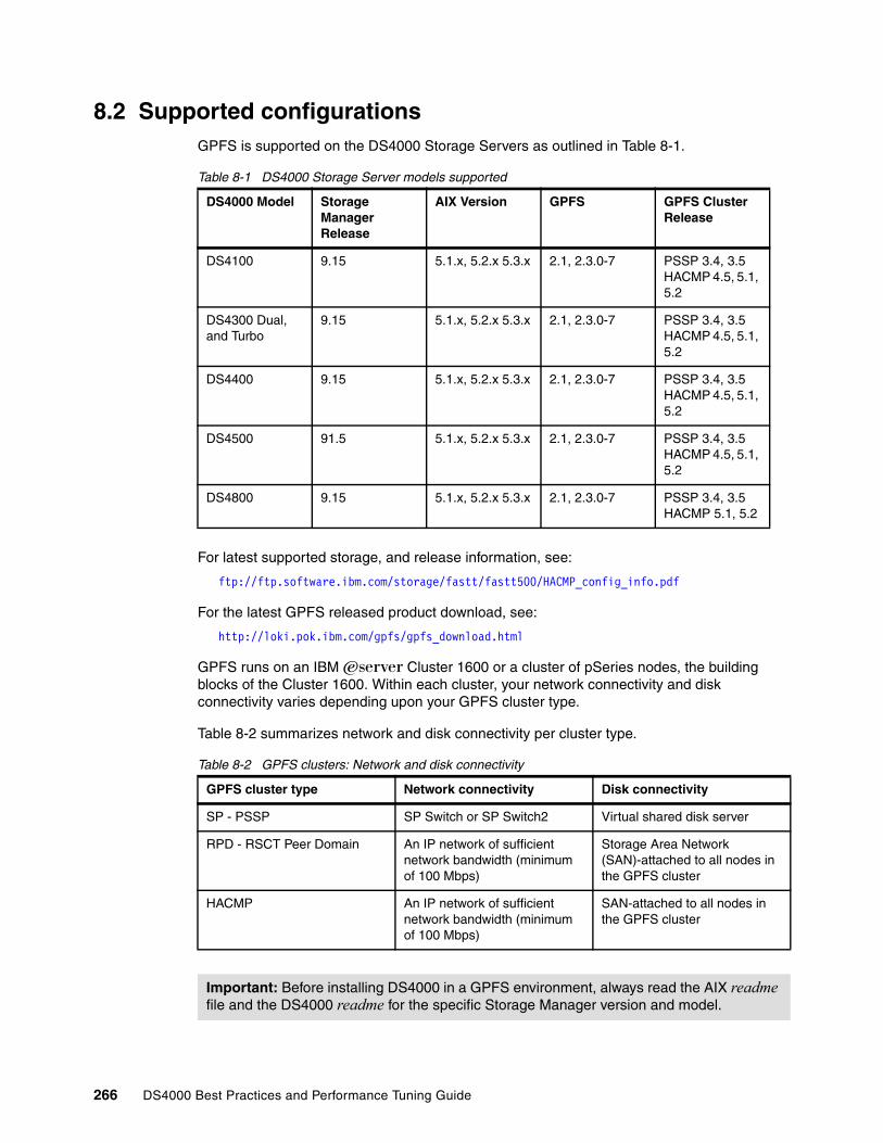
8.2 Supported configurationsGPFS is supported on the DS4000 Storage Servers as outlined in Table 8-1.
Table 8-1 DS4000 Storage Server models supported
For latest supported storage, and release information, see:
ftp://ftp.software.ibm.com/storage/fastt/fastt500/HACMP_config_info.pdf
For the latest GPFS released product download, see:
http://loki.pok.ibm.com/gpfs/gpfs_download.html
GPFS runs on an IBM Eserver Cluster 1600 or a cluster of pSeries nodes, the building blocks of the Cluster 1600. Within each cluster, your network connectivity and disk connectivity varies depending upon your GPFS cluster type.
Table 8-2 summarizes network and disk connectivity per cluster type.
Table 8-2 GPFS clusters: Network and disk connectivity
DS4000 Model Storage Manager Release
AIX Version GPFS GPFS Cluster Release
DS4100 9.15 5.1.x, 5.2.x 5.3.x 2.1, 2.3.0-7 PSSP 3.4, 3.5 HACMP 4.5, 5.1, 5.2
DS4300 Dual, and Turbo
9.15 5.1.x, 5.2.x 5.3.x 2.1, 2.3.0-7 PSSP 3.4, 3.5 HACMP 4.5, 5.1, 5.2
DS4400 9.15 5.1.x, 5.2.x 5.3.x 2.1, 2.3.0-7 PSSP 3.4, 3.5 HACMP 4.5, 5.1, 5.2
DS4500 91.5 5.1.x, 5.2.x 5.3.x 2.1, 2.3.0-7 PSSP 3.4, 3.5 HACMP 4.5, 5.1, 5.2
DS4800 9.15 5.1.x, 5.2.x 5.3.x 2.1, 2.3.0-7 PSSP 3.4, 3.5 HACMP 5.1, 5.2
GPFS cluster type Network connectivity Disk connectivity
SP - PSSP SP Switch or SP Switch2 Virtual shared disk server
RPD - RSCT Peer Domain An IP network of sufficient network bandwidth (minimum of 100 Mbps)
Storage Area Network (SAN)-attached to all nodes in the GPFS cluster
HACMP An IP network of sufficient network bandwidth (minimum of 100 Mbps)
SAN-attached to all nodes in the GPFS cluster
Important: Before installing DS4000 in a GPFS environment, always read the AIX readme file and the DS4000 readme for the specific Storage Manager version and model.
266 DS4000 Best Practices and Performance Tuning Guide

The SP cluster type and supported configurationsThe GPFS cluster type SP is based on the IBM Parallel System Support Programs (PSSP) licensed product and the shared disk concept of the IBM Virtual Shared Disk component of PSSP. In the GPFS cluster type SP (a PSSP environment), the nodes that are members of the GPFS cluster depend on the network switch type being used. In a system with an SP switch, the GPFS cluster is equal to all of the nodes in the corresponding SP partition that has GPFS installed. In a system with an SP Switch2, the GPFS cluster is equal to all of the nodes in the system that have GPFS installed. That is, the cluster definition is implicit and there is no need to run the GPFS cluster commands. Within the GPFS cluster, you define one or more nodesets within which your file systems operate.
In an SP cluster type, GPFS requires the Parallel System Support Programs (PSSP) licensed product and its IBM Virtual Shared Disk and IBM Recoverable Virtual Shared disk components (RVSD) for uniform disk access and recovery.
For the latest supported configurations, refer to:
ftp://ftp.software.ibm.com/storage/fastt/fastt500/PSSP-GPFS_config_info.pdf
RPD cluster type and supported configurationsThe GPFS cluster type RPD is based on the Reliable Scalable Cluster Technology (RSCT) subsystem of AIX 5L. The GPFS cluster is defined over an existing RSCT peer domain. The nodes that are members of the GPFS cluster are defined with the mmcrcluster, mmaddcluster, and mmdelcluster commands. With an RSCT peer domain, all nodes in the GPFS cluster have the same view of the domain and share the resources within the domain. Within the GPFS cluster, you define one or more nodesets within which your file systems operate.
In an RPD cluster type, GPFS requires the RSCT component of AIX. The GPFS cluster is defined on an existing RSCT peer domain with the mmcrcluster command.
For the latest supported configurations, refer to:
ftp://ftp.software.ibm.com/storage/fastt/fastt500/PSSP-GPFS_config_info.pdf
HACMP cluster type and supported configurationsThe GPFS cluster type HACMP is based on the IBM High Availability Cluster Multiprocessing/Enhanced Scalability for AIX (HACMP/ES) licensed product. The GPFS cluster is defined over an existing HACMP cluster. The nodes which are members of the GPFS cluster are defined with the mmcrcluster, mmaddcluster, and mmdelcluster commands. Within the GPFS cluster, you define one or more nodesets within which your file systems operate.
In an HACMP cluster type, GPFS requires the IBM HACMP/ES licensed product over which the GPFS cluster is defined with the mmcrcluster command.
General configuration limitationsThere are some general limitations to follow when configuring DS4000 Storage Servers in a GPFS environment:
� The FAStT200 is not supported in RVSD or GPFS on HACMP cluster configurations.
� DS4000 subsystems with EXP100 disk enclosures are not supported in RVSD or GPFS configurations at this time.
� RVSD and GPFS Clusters are not supported in Heterogeneous Server configurations.
Chapter 8. DS4000 and GPFS for AIX 267

� Only switched fabric connection, no direct connection, is allowed between the host node and DS4000.
� Each AIX host attaches to DS4000 Storage Servers using pairs of Fibre Channel adapters (HBAs):
– For each adapter pair, one HBA must be configured to connect to controller A, and the other to controller B.
– Each HBA pair must be configured to connect to a single partition in a DS4000 Storage Server or multiple DS4000 Storage Servers (fanout).
– To attach an AIX host to a single or multiple DS4000 Storage Servers with two partitions, 2 HBA pairs must be used.
� The maximum number of DS4000 partitions (host groups) per AIX host per DS4000 storage subsystem is two.
� A maximum of four partitions per DS4000 for RVSD and HACMP/GPFS clusters configurations.
� RVSD clusters can support a maximum of two IBM Virtual Shared Disk and RVSD servers per DS4000 partition.
� HACMP/GPFS clusters can support 2-32 servers per DS4000 partition. In this environment, be sure to read and understand the AIX device drivers queue depth settings as documented in the IBM TotalStorage DS4000 Storage Manager Version 9 Installation and Support Guide for AIX, HP-UX, Solaris, and Linux on Power, GC26-7705.
� Single Node Quorum is not supported in a two-node GPFS cluster with DS4000 disks in the configuration.
� SAN Switch zoning rules:
– Each HBA within a host must be configured in a separate zone from other HBAs within that same host when connected to the same DS4000 controller port. In other words, only one HBA within a host can be configured in the same zone with a given DS4000 controller port.
– The two hosts in a RVSD pair can share zones with each other.
� For highest availability, distributing the HBA and DS4000 connections across separate FC switches minimizes the effects of a SAN fabric failure.
� No logical drive on a DS4000 can be larger than 1 TB.
� You cannot protect your file system against disk failure by mirroring data at the LVM level. You must use GPFS replication or RAID devices to protect your data (DS4000 RAID levels).
268 DS4000 Best Practices and Performance Tuning Guide
Appendix A. DS4000 quick guide
In this appendix, we supply summarized information and pointers to DS4000 reference documentation. This is intended as a checklist and a quick guide to help you primarily during your planning and implementation of new systems.
Most of the topics summarized here have been presented and discussed in other chapters of this Best Practices guide.
A
© Copyright IBM Corp. 2005, 2006. All rights reserved. 269

A.1 Pre-installation checklist
Locate and review latest product documentation for DS4000:http://www.ibm.com/servers/storage/disk/ds4000/index.html
Download all software and firmware that is required: DS4000 Firmware, ESM, Drive firmware, HBA Firmware and drivers, RDAC, Storage Manager)
To be automatically notified of updates, register with MySupport (see Section 3.6.1, “Staying up-to-date with your drivers and firmware using My support” on page 101.)
Ensure that all hardware and software is covered by the interoperability matrix:http://www3.ibm.com/servers/storage/disk/ds4000/pdf/interop-matrix.pdf
Ensure that host operating systems that are planned to be connected are supported.
Ensure that power and environmental requirements are met:Each DS4000 and EXP unit will require two power sources.
Obtain 2 (or 4) IP addresses for the Storage serverCtrlA ___.____.____.____ CtrlA service: ___.____.____.____ (DS4800 only)CtrlB ___.____.____.____ CtrlB service: ___.____.____.____ (DS4800 only)
If needed, obtain IP addresses for switches or directors
Choose fabric design (direct connect or through switch or director).
Ensure that growth patterns are known and factored into design.
Ensure that the applications and data sets are reviewed and documented.
Decide on most critical application__________________________Note the type of application:
I/O intensive Throughput intensive
Plan for redundancy levels on storage (RAID Levels):It is best to map out each host with desired RAID level and redundancy required..
If required, plan for redundancy on host connections required (multiple HBAs with failover or load sharing)
Decide on premium features will be used with Storage System:– FlashCopy – VolumeCopy– Enhanced Remote Mirroring
Decide if SAN Volume Controller (SVC) is to be used.
Plan if there is a use or requirement of third party management tools such as Storage Performance Analyzer (SPA) or TotalStorage Productivity Center (TPC).
270 DS4000 Best Practices and Performance Tuning Guide

A.2 Installation tasksThis section summarizes the installation tasks and the recommended sequence.
A.2.1 Rack mounting and cabling
Mount server and expansion units into rack:
– Maintain 15 cm (6 in.) of clearance around your controller unit for air circulation.
– Ensure that the room air temperature is below 35°C (95°F).– Plan the controller unit installation starting from the bottom of the rack.– Remove the rack doors and side panels to provide easier access during installation.– Position the template to the rack so that the edges of the template do not overlap
any other devices.– Connect all power cords to electrical outlets that are properly wired and grounded.– Take precautions to prevent overloading the electrical outlets when you install
multiple devices in a rack.
Ensure for adequate future expansion capabilities when placing the different elements in the rack.
Perform drive side cabling between the DS4000 Server and Expansion enclosures. You can perform host-side cabling as well. The correct cabling depends on the DS4000 models being used:
For details see 3.2.1, “DS4100 and DS4300 host cabling configuration” on page 70.
DS4100 and DS4300 with dual controller
Appendix A. DS4000 quick guide 271
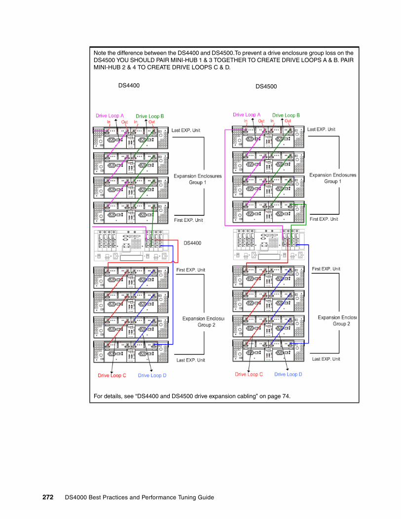
Note the difference between the DS4400 and DS4500.To prevent a drive enclosure group loss on the DS4500 YOU SHOULD PAIR MINI-HUB 1 & 3 TOGETHER TO CREATE DRIVE LOOPS A & B. PAIR MINI-HUB 2 & 4 TO CREATE DRIVE LOOPS C & D.
For details, see “DS4400 and DS4500 drive expansion cabling” on page 74.
DS4400 DS4500
272 DS4000 Best Practices and Performance Tuning Guide

For the DS4800, each drive-side Fibre Channel port shares a loop switch When attaching enclosures, drive loops are configured as redundant pairs utilizing one port from each controller. This ensures data access in the event of a path/loop or controller failure.
� Configure DS4800 with drive trays in multiples of four.� Distribute the drives equally between the drive trays.� For each disk array controller, use four Fibre Channel loops if you have more than 4 expansion
units.� Based on recommended cabling from above:
– Dedicate the drives in tray stacks 2 & 4 to disk array controller “B” – Dedicate the drives in tray stacks 1 & 3 to disk array controller “A” – I/O paths to each controller should be established for full redundancy and failover protection
For details, see“DS4800 drive expansion cabling” on page 78.
1 2 3 4
CtrlB
CtrlA
Host Mini-hubports
In port
Drive Mini-hubs
Out port
1 2 3 4
DS4400 / DS4500
HA1 HA2
Host system A with 2 HBAs
HB1 HB2
Host system B with 2 HBAs
SW1 SW2
Appendix A. DS4000 quick guide 273
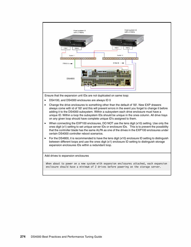
Ensure that the expansion unit IDs are not duplicated on same loop:
� DS4100, and DS4300 enclosures are always ID 0
� Change the drive enclosures to something other than the default of '00'. New EXP drawers always come with id of '00' and this will prevent errors in the event you forget to change it before adding it to the DS4000 subsystem. Within a subsystem each drive enclosure must have a unique ID. Within a loop the subsystem IDs should be unique in the ones column. All drive trays on any given loop should have complete unique ID's assigned to them.
� When connecting the EXP100 enclosures, DO NOT use the tens digit (x10) setting. Use only the ones digit (x1) setting to set unique server IDs or enclosure IDs. This is to prevent the possibility that the controller blade has the same ALPA as one of the drives in the EXP100 enclosures under certain DS4000 controller reboot scenarios.
� For the DS4800, it is recommended to have the tens digit (x10) enclosure ID setting to distinguish between different loops and use the ones digit (x1) enclosure ID setting to distinguish storage expansion enclosures IDs within a redundant loop.
Add drives to expansion enclosures
When about to power on a new system with expansion enclosures attached, each expansion enclosure should have a minimum of 2 drives before powering on the storage server.
274 DS4000 Best Practices and Performance Tuning Guide
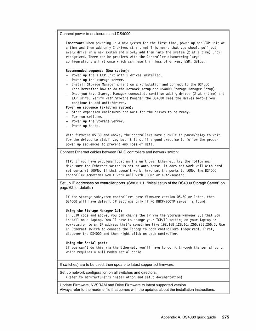
Connect power to enclosures and DS4000.
Important: When powering up a new system for the first time, power up one EXP unit at a time and then add only 2 drives at a time! This means that you should pull out every drive in a new system and slowly add them into the system (2 at a time) until recognized. There can be problems with the Controller discovering large configurations all at once which can result in loss of drives, ESM, GBICs.
Recommended sequence (New system): – Power up the 1 EXP unit with 2 drives installed.– Power up the storage server.– Install Storage Manager client on a workstation and connect to the DS4000
(see hereafter how to do the Network setup and DS4000 Storage Manager Setup).– Once you have Storage Manager connected, continue adding drives (2 at a time) and
EXP units. Verify with Storage Manager the DS4000 sees the drives before you continue to add units/drives.
Power on sequence (existing system):– Start expansion enclosures and wait for the drives to be ready.– Turn on switches.– Power up the Storage Server.– Power up hosts.
With firmware 05.30 and above, the controllers have a built in pause/delay to wait for the drives to stabilize, but it is still a good practice to follow the proper power up sequences to prevent any loss of data.
Connect Ethernet cables between RAID controllers and network switch:
TIP: If you have problems locating the unit over Ethernet, try the following:Make sure the Ethernet switch is set to auto sense. It does not work well with hard set ports at 100Mb. If that doesn't work, hard set the ports to 10Mb. The DS4000 controller sometimes won't work well with 100Mb or auto-sensing.
Set up IP addresses on controller ports. (See 3.1.1, “Initial setup of the DS4000 Storage Server” on page 62 for details.)
If the storage subsystem controllers have firmware version 05.30 or later, then DS4000 will have default IP settings only if NO DHCP/BOOTP server is found.
Using the Storage Manager GUI:In 5.30 code and above, you can change the IP via the Storage Manager GUI that you install on a laptop. You'll have to change your TCP/IP setting on your laptop or workstation to an IP address that's something like 192.168.128.10….255.255.255.0. Use an Ethernet switch to connect the laptop to both controllers (required). First, discover the DS4000 and then right click on each controller.
Using the Serial port:If you can't do this via the Ethernet, you'll have to do it through the serial port, which requires a null modem serial cable.
If switches) are to be used, then update to latest supported firmware.
Set up network configuration on all switches and directors.(Refer to manufacturer’s installation and setup documentation)
Update Firmware, NVSRAM and Drive Firmware to latest supported version Always refer to the readme file that comes with the updates about the installation instructions.
Appendix A. DS4000 quick guide 275

A.2.2 Preparing the host server
Install Host Bus Adapters (HBAs):
� Ensure that Host bus adapters (HBAs) used in hosts are updated to supported firmware and latest drivers.
For the latest supported host adapters, driver levels, bios, and updated readme, check:
http://knowledge.storage.ibm.com/HBA/HBASearch
� Configure HBA settings for operating system that will use the HBA:
Execution throttle (for Qlogic based HBAs) ________LUNs per target ________
Default for most operating systems is 0.(HP-UX, Netware 5.x and Solaris are limited to 32 LUNs)Netware 6.x with latest support packs and multi-path driver requires the setting of LUNs per target = 256).
� Ensure that additional host HBAs are installed if redundancy or load balancing is required.
� Ensure separate HBAs for Disk and Tape access:
For tape access – Enable Fibre Channel tape support.For disk access – Disable Fibre Channel tape support.
TIPS:– Be careful not to put all the high-speed adapters on a single system bus; otherwise
the computer bus becomes the performance bottleneck.– Make a note of what slot in each server.– Record WWPN of each HBA and what slot it is in.– On INTEL based host platforms, Ensure that HBAs are in a higher priority slot than
ServeRAID™ adapters. If not booting from the Host HBAs, it doesn't matter whether or not they are a higher PCI scan priority.
Ensure that latest version of RDAC is installed on each the host.For hosts that require RDAC, or if you plan to use other products such as the Veritas volume manager.
RDAC for Windows NT, Windows 2000 and Solaris (Regardless of whether or not there are multiple paths).
TIPS:
– RDAC is recommended regardless of whether or not there are multiple HBAs.
– AIX - The AIX “fcp.array” driver suite files (RDAC) are not included on the DS4000 installation CD. Either install them from the AIX Operating Systems CD, if the correct version is included, or download them from the Web site:
http://techsupport.services.ibm.com/server/fixes
276 DS4000 Best Practices and Performance Tuning Guide
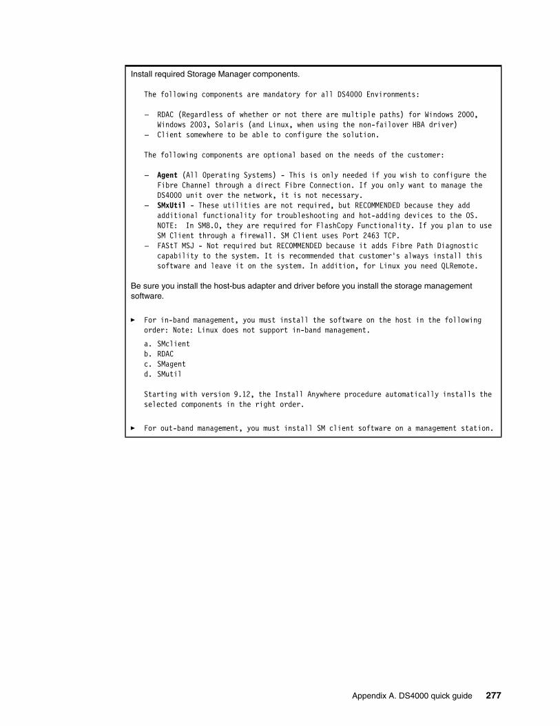
Install required Storage Manager components.
The following components are mandatory for all DS4000 Environments:
– RDAC (Regardless of whether or not there are multiple paths) for Windows 2000, Windows 2003, Solaris (and Linux, when using the non-failover HBA driver)
– Client somewhere to be able to configure the solution.
The following components are optional based on the needs of the customer:
– Agent (All Operating Systems) - This is only needed if you wish to configure the Fibre Channel through a direct Fibre Connection. If you only want to manage the DS4000 unit over the network, it is not necessary.
– SMxUtil - These utilities are not required, but RECOMMENDED because they add additional functionality for troubleshooting and hot-adding devices to the OS.NOTE: In SM8.0, they are required for FlashCopy Functionality. If you plan to use SM Client through a firewall. SM Client uses Port 2463 TCP.
– FAStT MSJ - Not required but RECOMMENDED because it adds Fibre Path Diagnostic capability to the system. It is recommended that customer's always install this software and leave it on the system. In addition, for Linux you need QLRemote.
Be sure you install the host-bus adapter and driver before you install the storage management software.
� For in-band management, you must install the software on the host in the following order: Note: Linux does not support in-band management.
a. SMclientb. RDACc. SMagentd. SMutil
Starting with version 9.12, the Install Anywhere procedure automatically installs the selected components in the right order.
� For out-band management, you must install SM client software on a management station.
Appendix A. DS4000 quick guide 277

A.2.3 Storage Manager setup
Keep accurate and up to date documentation. Consider a change control log.
Launch Storage Manager and perform initial discovery.
When first started on a management workstation, the client software displays the Enterprise Management window and the Confirm Initial Automatic Discovery window.
Note: The Enterprise Management window can take several minutes to open. No wait cursor (such as an hourglass) is displayed.
Click Yes to begin an initial automatic discovery of hosts and storage subsystems attached to the local subnetwork.
Note: The Enterprise Management window can take up to a minute to refresh after an initial automatic discovery.
Direct Management: If the Automatic Discovery doesn't work.• Go to EDIT > Add Device• Enter the IP Address of controller A. Click Add. • Enter IP Address for controller B. Click Add. • Click Done.
Storage Controllers should appear. For new installs, it is likely that they will show “Needs Attention”. This is common since the battery will be charging. Power cycle the DS4000 controller if it doesn't appear.
Rename the DS4000 storage server
– Click Storage Subsystem > Rename. The Rename Storage Subsystem window opens.– Type the name of the storage subsystem. Then click OK.
If you have multiple controllers, it is helpful to enter the IP addresses or some other unique identifier for each subsystem controller.
Change expansion enclosure order
The EXP enclosures will likely show in the GUI different than how you have them installed into the rack. You can change the GUI to look like how the enclosures are installed. You do this by going under File>Change>Enclosure Order and move the enclosures up or down to correctly reflect how they are installed into the rack.
Check that each controller (CtrA and CtrlB) is online and active.
Collect the Storage Server system profile.
Go to View > Storage System ProfileClick on Controller Tab and Make note of NVSRAM and Firmware versions listed
Firmware version: _______________________NVSRAM version: _______________________
Click on the “Drives” tab and find the product ID and Firmware version.HDD Firmware ___________
Click on the “Enclosures” tab and find the ESM Firmware version for each EXP unit (all EXP of the same model should have the same version)
ESM _____________
If you need to upgrade the firmware, always refer to the documentation supplied with the firmware.
Set password on storage server and document the password in a secure area.
278 DS4000 Best Practices and Performance Tuning Guide

Set Storage Server settings.
Set start and stop cache levels as per planning document ___________Set cache block size as per planning document _______K
Create array(s) and logical drives as per planning document (repeat for each array/logical drive).
Select how many drives per array: _________Ensure alternating drive loops (odds and evens)
How many LUNs per array _________Speed of drives in the array _________KChoose RAID level RAID_____Disk Type SATA____ Disk type Fibre Channel________
The recommendation is to do a manual selection of drives and configuration to ensure that:Drives use both drive loops (odds and evens)
Enclosure Loss Protection
Ensure that a small amount of free space is left on each array after logical drive creation
Read ahead multiplier _______
Select segment size _______K
Select controller to ensure a balance of workload between controllers
Note: No more than 30 drives per array. Best performance around 5 to 12 drives.Max 2 TB per LUN
Configure cache settings required for that logical drive:
Read caching enabled Yes__ No___Write caching enabled Yes__ No___Write caching without batteries Yes__ No___Write caching with mirroring Yes__ No___
Configure host access to logical drive.
If using Storage Partitioning, ensure that it is enabled:
DS4300 does not come with Storage Partitioning enabled. There is an activation kit that comes with the storage system that will point you to a Web site for key activation.
DS4400 has 64 storage partitions installed. No additional storage partitioning premium feature options can be purchased for this model.
DS4500 has 16 storage partitions installed. An upgrade from 16 to 64 partition storage partitioning premium feature option can be purchased.
Procedure:Go to Storage Subsystem>Premium Features>List
You should see “Storage Partitioning Enabled”
If you do not see that it is enabled you'll have to get the feature key and enable it. Make note of the 32 digit feature key number. Call 800-IBM-SERV, enter the 4 digit machine type and tell the help desk that you need a feature key generated.
Appendix A. DS4000 quick guide 279
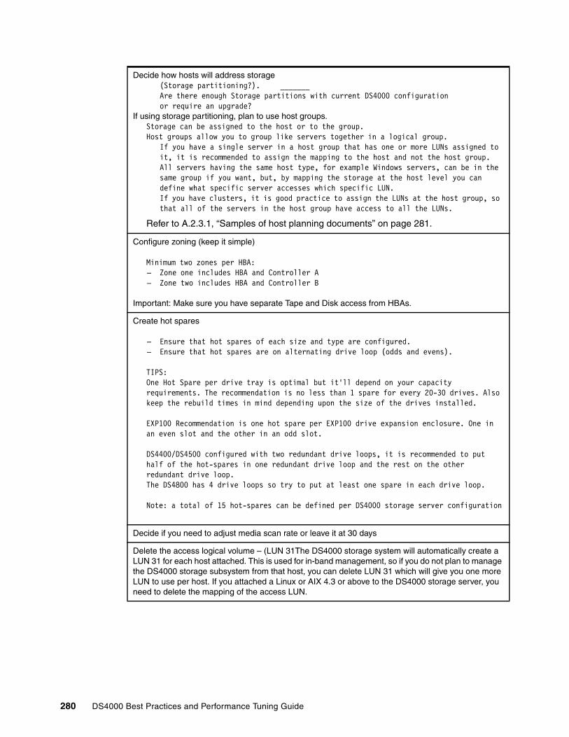
Decide how hosts will address storage(Storage partitioning?). _______Are there enough Storage partitions with current DS4000 configuration or require an upgrade?
If using storage partitioning, plan to use host groups. Storage can be assigned to the host or to the group. Host groups allow you to group like servers together in a logical group.
If you have a single server in a host group that has one or more LUNs assigned to it, it is recommended to assign the mapping to the host and not the host group. All servers having the same host type, for example Windows servers, can be in the same group if you want, but, by mapping the storage at the host level you can define what specific server accesses which specific LUN.If you have clusters, it is good practice to assign the LUNs at the host group, so that all of the servers in the host group have access to all the LUNs.
Refer to A.2.3.1, “Samples of host planning documents” on page 281.
Configure zoning (keep it simple)
Minimum two zones per HBA:– Zone one includes HBA and Controller A– Zone two includes HBA and Controller B
Important: Make sure you have separate Tape and Disk access from HBAs.
Create hot spares
– Ensure that hot spares of each size and type are configured.– Ensure that hot spares are on alternating drive loop (odds and evens).
TIPS:One Hot Spare per drive tray is optimal but it'll depend on your capacity requirements. The recommendation is no less than 1 spare for every 20-30 drives. Also keep the rebuild times in mind depending upon the size of the drives installed.
EXP100 Recommendation is one hot spare per EXP100 drive expansion enclosure. One in an even slot and the other in an odd slot.
DS4400/DS4500 configured with two redundant drive loops, it is recommended to put half of the hot-spares in one redundant drive loop and the rest on the other redundant drive loop. The DS4800 has 4 drive loops so try to put at least one spare in each drive loop.
Note: a total of 15 hot-spares can be defined per DS4000 storage server configuration
Decide if you need to adjust media scan rate or leave it at 30 days
Delete the access logical volume – (LUN 31The DS4000 storage system will automatically create a LUN 31 for each host attached. This is used for in-band management, so if you do not plan to manage the DS4000 storage subsystem from that host, you can delete LUN 31 which will give you one more LUN to use per host. If you attached a Linux or AIX 4.3 or above to the DS4000 storage server, you need to delete the mapping of the access LUN.
280 DS4000 Best Practices and Performance Tuning Guide

A.2.3.1 Samples of host planning documentsThe following are examples of documents that should be prepared when planning host attachment to the DS4000.
� Example of zoning planning document
� Example of host and LUN settings for environment
� Example of LUN settings for each host
Zone Host Name
WWN Cont Switch SW Port
Host OS
Radon- HBA1 Radon 21-00-00-E0-8B-05-4C-AA A SW1 5 Win2000
Radon- HBA1 Radon 21-00-00-E0-8B-05-4C-AA B SW1 5 Win2000
Radon- HBA2 Radon 21-00-00-E0-8B-18-62-8E A SW2 6 Win2000
Radon– HBA2 Radon 21-00-00-E0-8B-18-62-8E B SW2 6 Win2000
LUN Name Use No# HBAs
RAID Level
# of Disks in LUN
Current Size
%Read Growth
Radon_DB OLTP DB 2 1 8 100Gb 63% 50%
Radon_Trans Transac-tion Logs
2 1 2 50Gb 14% 50%
Nile_Backup Backup 1 5 8 750Gb 50% 30%
AIX_Cluster AIX Cluster 2 1 10 250Gb 67% 40%
AIX_Cluster AIX Cluster 2 1 10 250Gb 67% 40%
Netware File 1 5 3 200Gb 70% 35%
Host Name LUN Segment Size
Write Cache
Read Cache Write Cache with Mirror-ing
Read Ahead Multip.
Radon Radon_DB 64 Enabled Enabled Enabled 0
Radon Radon_Trans 128 Enabled Enabled Enabled 0
Nile Nile_Backup 256 Enabled Enabled Disabled 1
Kanaga AIX_Cluster 128 Enabled Enabled Enabled 1
Atlantic AIX_Cluster 128 Enabled Enabled Enabled 1
Pacific Netware 128 Enabled Enabled Enabled 1
Appendix A. DS4000 quick guide 281

A.2.4 Tuning for performance.
Use performance monitor to view the performance of the logical drives on the system.Adjust settings that may improve performance then monitor results, then compare results.Settings that may be changed on a logical drive to tune for performance.
Segment size:
Old Segment Size _______K New Segment Size ______K
Cache settings changes Changed
Read caching enabled Yes _ No _ _Write caching enabled Yes _ No _ _Write caching without batteries Yes _ No _ _Write caching with mirroring Yes _ No _ _
Read ahead multiplier
Old Read Ahead ______ New Read Ahead ______
If multiple logical drives exist on the same array then check for disk contention or thrashing of disks.
Use performance monitor to check performance statistics on the DS4000 storage server.
Look at all the statistics:� Total IOs� Read Percentage� Cache Hit Percentage� Current KB/Sec� Max KB/Sec� Current IO/Sec� Max IO/Sec
From these you can gauge which LUNs are high utilization LUNs and adjust settings to suit each LUN.
Use performance monitor to check controller balance.
Do any arrays or LUNs need to be set to another controller to even out workload?
Yes _ No_
282 DS4000 Best Practices and Performance Tuning Guide
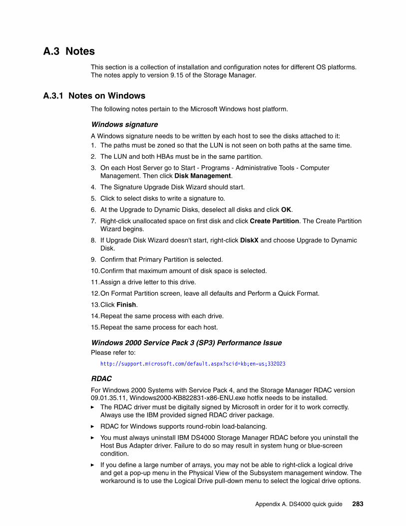
A.3 NotesThis section is a collection of installation and configuration notes for different OS platforms. The notes apply to version 9.15 of the Storage Manager.
A.3.1 Notes on WindowsThe following notes pertain to the Microsoft Windows host platform.
Windows signature
A Windows signature needs to be written by each host to see the disks attached to it:1. The paths must be zoned so that the LUN is not seen on both paths at the same time.
2. The LUN and both HBAs must be in the same partition.
3. On each Host Server go to Start - Programs - Administrative Tools - Computer Management. Then click Disk Management.
4. The Signature Upgrade Disk Wizard should start.
5. Click to select disks to write a signature to.
6. At the Upgrade to Dynamic Disks, deselect all disks and click OK.
7. Right-click unallocated space on first disk and click Create Partition. The Create Partition Wizard begins.
8. If Upgrade Disk Wizard doesn't start, right-click DiskX and choose Upgrade to Dynamic Disk.
9. Confirm that Primary Partition is selected.
10.Confirm that maximum amount of disk space is selected.
11.Assign a drive letter to this drive.
12.On Format Partition screen, leave all defaults and Perform a Quick Format.
13.Click Finish.
14.Repeat the same process with each drive.
15.Repeat the same process for each host.
Windows 2000 Service Pack 3 (SP3) Performance IssuePlease refer to:
http://support.microsoft.com/default.aspx?scid=kb;en-us;332023
RDAC
For Windows 2000 Systems with Service Pack 4, and the Storage Manager RDAC version 09.01.35.11, Windows2000-KB822831-x86-ENU.exe hotfix needs to be installed.� The RDAC driver must be digitally signed by Microsoft in order for it to work correctly.
Always use the IBM provided signed RDAC driver package.
� RDAC for Windows supports round-robin load-balancing.
� You must always uninstall IBM DS4000 Storage Manager RDAC before you uninstall the Host Bus Adapter driver. Failure to do so may result in system hung or blue-screen condition.
� If you define a large number of arrays, you may not be able to right-click a logical drive and get a pop-up menu in the Physical View of the Subsystem management window. The workaround is to use the Logical Drive pull-down menu to select the logical drive options.
Appendix A. DS4000 quick guide 283

Updating RDAC in a Microsoft Cluster Services configurationIn Microsoft Cluster Services (MSCS) configurations, the MSCS service must be stopped and set to manual start after server rebooting, the clusdisk driver must have to be set to offline and, then, the server must be rebooted before uninstalling the RDAC driver in the server. If the clusdisk driver is not set to offline and the MSCS service is not set to manual start, the Microsoft Cluster Service will not start after the new RDAC driver is installed because it can not bring the Quorum disk resource online. The problem is caused by the changing of the disk signatures.
To recover from this problem, you must:
� Look up the old disk signatures of the disk that are defined as cluster disk resources. They could be found either in the registry under the registry key:
HKLM/System/CurrentControlSet/Services/Clusdisk/Parameters/Signatures
Or, in the cluster.log file.
� Look up the new disk signatures of the disks that are defined as cluster disk resources using the dumpcfg utility that is packaged in the Microsoft Windows resource kit.
� Compare the new and old disk signatures. If new disk signature did not match the old signature, you have to change the new disk signature to the old disk signature values by using the dumpcfg command. The syntax of the command is:
dumpcfg.exe -s <old-signature> <Disk#>
For example, dumpcfg.exe -s 12345678 0
Always check in the latest documentation from Microsoft regarding this procedure.
Host typeEnsure that the host type is set correctly for the version of operating system. The Host Type setting configures how the host will access the DS4000 system. For example, do not set the host type for a Windows 2003 Non-Clustered server to Windows NT® Non-Clustered SP5 or Higher host type, otherwise this could extend the boot time (to up to two hours).
Disk alignmentUse diskpar.exe from the Windows 2000 Resource kit to align the storage boundaries. Note that diskpar is for Windows 2000 and Windows 2003. The diskpar functionality was put into diskpart.exe with Windows Server 2003 Service Pack 1. This is explained in more detail in “Disk alignment” on page 124.
Extend disksFor Windows 2003 basic disks, you can extend the volume using the extend command in the diskpart utility. This will extend the volume to the full size of the disk. This command is dynamic and can be done while the system is in operation.
Use the Disk Management GUI to extend dynamic disks in Windows 2000 or Windows 2003.
Note that a system partition cannot be extended.
This is explained in more detail in “Using diskpart to extend a basic disk” on page 121.
Limitations of booting from the DS4000 with WindowsWhen the server is configured to boot the Windows operating system from the DS4000 storage server, and to have storage access and path redundancy, the following limitations apply:
284 DS4000 Best Practices and Performance Tuning Guide

� It is not possible to boot from of a DS4000 Storage Server and use it as a clustering device. This is a Microsoft Windows physical limitation.
� If there is a path failure and the host is generating I/O, the boot drive will move to the other path. However, while this transition is occurring, the system will appear to halt for up to 30 seconds.
� If the boot device (LUN 0) is not on the same path as the bootable HBA port, you will receive an INACCESSIBLE_BOOT_DEVICE error message.
� If you suffer major path problems (LIPs) or path trashing, it can hang the server indefinitely as RDAC tries to find a stable path.
� By booting from the DS4000 storage device, most of the online diagnostic strategies are effectively canceled, and path problem determination must be done from the Ctrl+Q diagnostics panel instead of FAStT MSJ.
� The internal disk devices should not be re-enabled.
If booting from the DS4000 disk on a host server that has two HBAs and the HBA that is configured as the boot device fails, use the following procedure to change the boot device from the failed HBA to the other HBA:
� During the system boot process, press Ctrl+Q at the Qlogic BIOS stage.
Figure 8-2 QLogic HBA Bios
� Select the first adapter at the 2400 I/O address (the failed adapter)� On the failed HBA, the Host Adapter BIOS should be set to disabled.� Save and exit back to the Select Adapter menu.� Select second adapter at the 2600 I/O address.� The second HBA on the Host Adapter BIOS should be set to enabled.
Appendix A. DS4000 quick guide 285
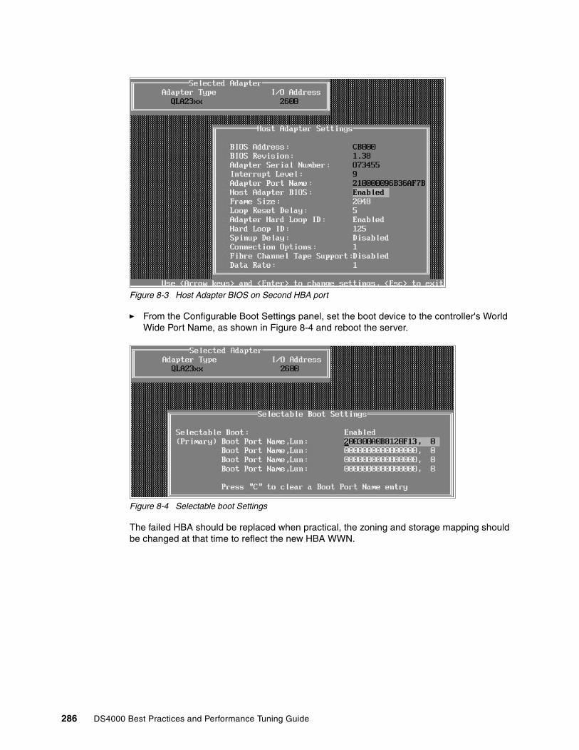
Figure 8-3 Host Adapter BIOS on Second HBA port
� From the Configurable Boot Settings panel, set the boot device to the controller's World Wide Port Name, as shown in Figure 8-4 and reboot the server.
Figure 8-4 Selectable boot Settings
The failed HBA should be replaced when practical, the zoning and storage mapping should be changed at that time to reflect the new HBA WWN.
286 DS4000 Best Practices and Performance Tuning Guide
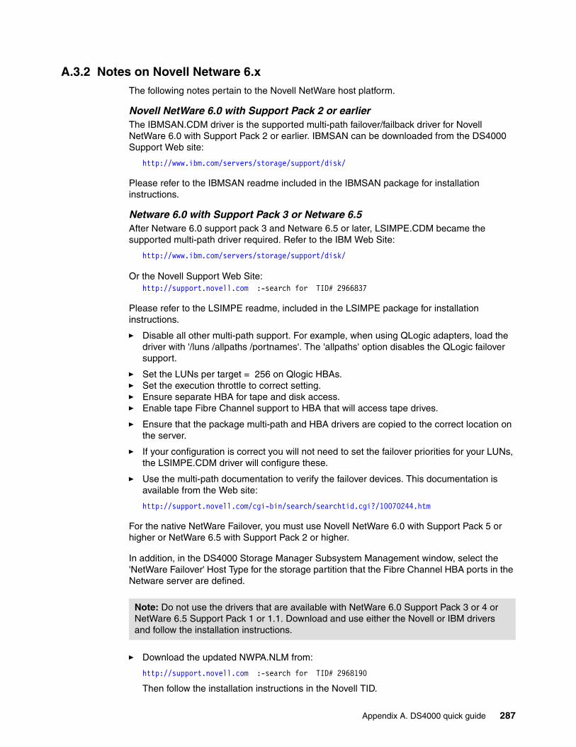
A.3.2 Notes on Novell Netware 6.x The following notes pertain to the Novell NetWare host platform.
Novell NetWare 6.0 with Support Pack 2 or earlierThe IBMSAN.CDM driver is the supported multi-path failover/failback driver for Novell NetWare 6.0 with Support Pack 2 or earlier. IBMSAN can be downloaded from the DS4000 Support Web site:
http://www.ibm.com/servers/storage/support/disk/
Please refer to the IBMSAN readme included in the IBMSAN package for installation instructions.
Netware 6.0 with Support Pack 3 or Netware 6.5After Netware 6.0 support pack 3 and Netware 6.5 or later, LSIMPE.CDM became the supported multi-path driver required. Refer to the IBM Web Site:
http://www.ibm.com/servers/storage/support/disk/
Or the Novell Support Web Site:http://support.novell.com :-search for TID# 2966837
Please refer to the LSIMPE readme, included in the LSIMPE package for installation instructions.
� Disable all other multi-path support. For example, when using QLogic adapters, load the driver with '/luns /allpaths /portnames'. The 'allpaths' option disables the QLogic failover support.
� Set the LUNs per target = 256 on Qlogic HBAs.� Set the execution throttle to correct setting.� Ensure separate HBA for tape and disk access.� Enable tape Fibre Channel support to HBA that will access tape drives.
� Ensure that the package multi-path and HBA drivers are copied to the correct location on the server.
� If your configuration is correct you will not need to set the failover priorities for your LUNs, the LSIMPE.CDM driver will configure these.
� Use the multi-path documentation to verify the failover devices. This documentation is available from the Web site:
http://support.novell.com/cgi-bin/search/searchtid.cgi?/10070244.htm
For the native NetWare Failover, you must use Novell NetWare 6.0 with Support Pack 5 or higher or NetWare 6.5 with Support Pack 2 or higher.
In addition, in the DS4000 Storage Manager Subsystem Management window, select the 'NetWare Failover' Host Type for the storage partition that the Fibre Channel HBA ports in the Netware server are defined.
� Download the updated NWPA.NLM from:
http://support.novell.com :-search for TID# 2968190
Then follow the installation instructions in the Novell TID.
Note: Do not use the drivers that are available with NetWare 6.0 Support Pack 3 or 4 or NetWare 6.5 Support Pack 1 or 1.1. Download and use either the Novell or IBM drivers and follow the installation instructions.
Appendix A. DS4000 quick guide 287

� Download the newer MM.NLM from:
http://support.novell.com :-search for TID# 2968794
Then follow the installation instructions in the Novell TID.
� After the Device Driver is installed, edit the STARTUP.NCF for the following lines:
– Add 'SET MULTI-PATH SUPPORT = ON'– Add 'Load LSIMPE.CDM' before the SCSIHD.CDM driver– Add the 'AEN' command line option to SCSIHD.CDM
Your STARTUP.NCF file should look somewhat like the following example:
SET Multi-path Support = ONLOAD MPS14.PSM LOAD IDECD.CDM LOAD IDEHD.CDMLOAD LSIMPE.CDMLOAD SCSIHD.CDM AENLOAD IDEATA.HAM SLOT=10007 LOAD ADPT160M.HAM SLOT=10010 LOAD QL2300.HAM SLOT=4 /LUNS /ALLPATHS /PORTNAMES XRETRY=400
288 DS4000 Best Practices and Performance Tuning Guide
A.3.3 Notes on LinuxThere are two versions of the Linux RDAC. The version (09.00.A5.09)for Linux 2.4 kernels only like Red Hat EL 3 and SuSe SLES 8 and RDAC package version 09.01.B5.XX for Linux 2.6 kernel environment.
� Make sure you read the README.TXT files for V9.15 Linux RDAC, HBA and Storage Manager for Linux.
� When using the Linux RDAC as the multi-pathing driver, the LNXCL host type must be used.
� There is not a requirement that the UTM (Access LUN) must be removed from the LNXCL Storage Partitioning partition.
� When using the Linux RDAC as the failover/failback driver, the host type should be set to LNXCL instead of Linux. If Linux RDAC is not used, the host type of Linux must be used instead.
� The Linux RDAC driver cannot co-exist with a HBA-level multi-path failover/failback driver such as the 6.06.63-fo driver. You might have to modify the driver make file for it to be compiled in the non-failover mode.
� Auto Logical Drive Transfer (ADT/AVT) mode is not supported when using Linux in a cluster, or when using RDAC. Since ADT(AVT) is automatically enabled in the Linux storage partitioning host type. It has to be disabled by selecting 'host type' of LNXCL.
� AVT is required if you are using the Qlogic Failover drivers.
� The Linux SCSI layer does not support skipped (sparse) LUNs. If the mapped LUNs are not contiguous, the Linux kernel will not scan the rest of the LUNs. Therefore, the LUNs after the skipped LUN will not be available to the host server. The LUNs should always be mapped using consecutive LUN numbers.
� Although the host server can have different FC HBAs from multiple vendors or different FC HBA models from the same vendors, only one model of FC HBAs can be connected to the IBM DS4000 Storage Servers.
� If a host server has multiple HBA ports and each HBA port sees both controllers (via an un-zoned switch), the Linux RDAC driver may return I/O errors during controller failover.
� Linux SCSI device names have the possibility of changing when the host system reboots. We recommend using a utility such as devlabel to create user-defined device names that will map devices based on a unique identifier, called a UUID. The devlabel utility is available as part of the Red Hat Enterprise Linux 3 distribution, or online at:
http://www.lerhaupt.com/devlabel/devlabel.html
� Linux RDAC supports re-scanning to recognize a newly mapped LUN without rebooting the server. The utility program is packed with the Linux RDAC driver. It can be invoked by using either hot_add or mppBusRescan command (note that hot_add is a symbolic link to mppBusRescan). There are man pages for both commands. However, the Linux RDAC driver doesn't support LUN deletion. One has to reboot the server after deleting the mapped logical drives.
Appendix A. DS4000 quick guide 289
A.3.4 Notes on AIX The following notes pertain to the AIX environment.
RequirementsMake sure you have these fileset versions or later. PTF/APARs can be downloaded from Web site:
http://techsupport.services.ibm.com/server/aix.fdc
� AIX 5.3, BASE
devices.fcp.disk.array.diag 5.3.0.0 devices.fcp.disk.array.rte 5.3.0.20 devices.common.IBM.fc.rte 5.3.0.0 devices.pci.df1000f7.com 5.3.0.21 devices.pci.df1000f7.rte 5.3.0.0 devices.pci.df1000f9.rte 5.3.0.0 devices.pci.df1000fa.rte 5.3.0.10
� AIX 5.2, Maintenance Level 4 and the following AIX fileset versions:
devices.fcp.disk.array.diag 5.2.0.30 devices.fcp.disk.array.rte 5.2.0.60 devices.common.IBM.fc.rte 5.2.0.50 devices.pci.df1000f7.com 5.2.0.60 devices.pci.df1000f7.rte 5.2.0.30 devices.pci.df1000f9.rte 5.2.0.30 devices.pci.df1000fa.rte 5.2.0.50
� AIX 5.1, Maintenance Level 6 and the following AIX fileset versions:
devices.fcp.disk.array.diag 5.1.0.51 devices.fcp.disk.array.rte 5.1.0.65 devices.common.IBM.fc.rte 5.1.0.51 devices.pci.df1000f7.com 5.1.0.64 devices.pci.df1000f7.rte 5.1.0.37 devices.pci.df1000f9.rte 5.1.0.37
� AIX 4.3 contains no support for features beyond Storage Manager 8.3.
Host Bus Adapters
The supported Host Bus Adapter(s) are: IBM Feature Code 6227, 6228, 6239, or 5716 with the following HBA firmware levels:
FC 6227 - 3.30X1 FC 6228 - 3.91A1 FC 6239 - 1.81X1 FC 5716 - 1.90A4
For booting from DS4000, the following HBA Firmware levels are required:FC 6227 - 3.22A1 or above FC 6228 - 3.82A01 or aboveFC 6239 - 1.00X5 or aboveFC 5716 - 1.90A4
Important: With AIX 5.3, download the complete maintenance package and update all PTFs together. Do not install each PTF separately.
290 DS4000 Best Practices and Performance Tuning Guide
AIX configuration and usage notesThe following notes pertain to the AIC configuration:
1. Dynamic Volume Expansion (DVE) is only supported on AIX 5.2 and 5.3. AIX 5.3 must have PTF U499974 installed before using DVE.
2. In-band Storage Management is supported on AIX 5.1 and 5.2.
3. Booting up from a DS4000 device is supported only on AIX 5.1 and 5.2.
– SAN (switch) ports should be configured an F port (some switches/directors default ports to type Gx.)
– Use the SAN switch/director management console to force the port to F.
4. Online upgrades are not supported on AIX 4.3.3. I/O must be quiesced prior to performing the upgrade.
5. Online concurrent firmware and NVSRAM upgrades of FC arrays are only supported when upgrading from 06.10.06.XX to another version of 06.10.XX.XX. There is an exception for DS4800’s for 9.12 to 9.15.
APAR_aix_51 = IY64463APAR_aix_52 = IY64585APAR_aix_53 = IY64475
It is highly recommended that online firmware upgrades be scheduled during low peak I/O loads.
Upgrading firmware from 05.xx.xx.xx to version 06.xx.xx.xx must be performed with no IOs. There is no work-around.
6. Interoperability with IBM 2105 and SDD Software is supported on separate HBA and switch zones.
7. Interoperability with tape devices is supported on separate HBA and switch zones.
8. When using FlashCopy, the Repository Volume failure policy must be set to Fail FlashCopy logical drive, which is the default setting. The Fail writes to base logical drive policy is not supported on AIX, as data could be lost to the base logical drive.
9. It is important to set the queue depth to a correct size for AIX hosts. Having too large of a queue depth can result in lost file systems and host panics.
10.F-RAID Manager is not supported.
11.For most installations, AIX hosts attach to DS4000 with pairs of HBAs. For each adapter pair, one HBA must be configured to connect to controller “A” and the other to controller “B”. An AIX host with 4 HBAs will require you to configure 2 DS partitions (or Host Groups).
12.Each AIX host (server) can support 1 or 2 DS4000 Partitions (or Host Groups), each with a maximum of 256 Logical Drives (AIX 5.1 or 5.2 and SM8.4).
– AIX 4.3.3 is restricted to 32 Logical Drives on each partition.
13.Single-switch configurations are allowed, but each HBA and DS4000 controller combination must be in a separate SAN zone.
14.Single HBA configurations are allowed, but each single HBA configuration requires that both controllers in the DS4000 be connected to the host.
– In a switch environment, both controllers must be connected to the switch within the same SAN zone as the HBA.
– In a direct-attach configurations, both controllers must be “daisy-chained” together. This can only be done on DS4400 or DS4500.
Appendix A. DS4000 quick guide 291

15.When you start from a DS4000 device, both paths to the boot device must be up and operational.
16.Path failover is not supported during the AIX boot process. Once the AIX host has started, failover operates normally.
SAN zoningObserve the following:
1. Multiple HBAs within the same server cannot see the same DS4000 controller port.
2. The HBAs are isolated from each other (zoned) if they are connected to the same switch that is connected to the same DS4000 controller port.
3. Each fibre-channel HBA and controller port must be in its own fabric zone, if they are connecting through a single fibre-channel switch, such as 2109-F16.
Single HBA configurations are allowed, but each single HBA configuration requires that both controllers in the DS4000 be connected to the host� In a switch environment, both controllers must be connected to the switch and separate
zones setup, so that the host HBA has access to both controllers.
For Example: Zone one has the HBA and Controller A, and Zone 2 has HBA and Controller B.
� In a direct-attach configurations, both controllers must be “daisy-chained” together.
Other restrictionsWhen booting up your system:
� If you create more than 32 LUNs on a partition, you cannot use the release CD to install AIX on a DS4000 device on that partition. Therefore, if your system is booted from a DS4000 device, do not create more than 32 LUNs on the partition that you are booting from.
� When you boot your system from a DS4000 device, both paths to the DS4000 storage server must be up and running. The system cannot use path failover during the AIX boot process. Once the AIX host has started, failover operates normally.
� You cannot boot your system from any device that has one or more EXP100 SATA expansion units attached.
Partitioning restrictions:
� The maximum number of partitions per AIX host, per DS4000 storage server, is two.
� All logical drives that are configured for AIX must be mapped to an AIX host group. On each controller, you must configure at least one LUN with an ID between 0 and 31 that is not a UTM or access logical drive.
Important: The DS4000 should be configured with at least 1 LUN assigned to the AIX server before the AIX server is allowed to see the DS. This prevents problems with the auto-generated dac/dar relationship.
292 DS4000 Best Practices and Performance Tuning Guide
Related publications
The publications listed in this section are considered particularly suitable for a more detailed discussion of the topics covered in this redbook.
IBM RedbooksFor information on ordering these publications, see “How to get IBM Redbooks” on page 294. Note that some of the documents referenced here may be available in softcopy only.
� IBM TotalStorage DS4000 Series and Storage Manager, SG24-7010-2
� Introducing IBM TotalStorage FAStT EXP100 with SATA Disks, REDP-3794-00
� IBM TotalStorage Solutions for xSeries, SG24-6874
� Introduction to Storage Area Networks, SG24-5470-01
� IBM TotalStorage Solutions for xSeries, SG24-6874
� Introduction to Storage Area Networks, SG24-5470-01
� IBM SAN Survival Guide, SG24-6143-01
� IBM SAN Survival Guide Featuring the IBM 2109, SG24-6127
� AIX 5L Performance Tools Handbook, SG24-6039-01
� IBM HACMP for AIX V5.X Certification Study Guide, SG24-6375-00
Other publicationsThese publications are also relevant as further information sources:
� IBM TotalStorage DS4000 Storage Manager Version 9 Concepts Guide, GC26-7734-01
� IBM DS4000 Storage Manager Version 9 Installation and Support Guide for Windows 2000, Windows Server 2003, NetWare, ESX Server, and Linux, GC26-7706-02
� IBM DS4000 Storage Manager Version 9 Installation and Support Guide for AIX, HP-UX, Solaris, and Linux on POWER, GC26-7705-02
� IBM TotalStorage DS4000 Storage Manager Version 9 Copy Services Guide, GC26-7707-02
� IIBM TotalStorage DS4000 FC2-133 Host Bus Adapter Installation and User's Guide, GC26-7736-00
� IBM TotalStorage DS4000 Hardware Maintenance Manual, GC26-7702-00
� IBM TotalStorage DS4000 Hard Drive and Storage Expansion Enclosure Installation and Migration Guide, GC26-7704-01
� IBM TotalStorage DS4000 Problem Determination Guide, GC26-7703-01
� IBM TotalStorage DS4000 Fibre Channel and Serial ATA Intermix Premium Feature Installation Overview, GC26-7713-03
� IBM TotalStorage DS4500 Fibre Channel Storage Server Installation and Support Guide, GC26-7727-00
� IBM TotalStorage DS4500 Fibre Channel Storage Server User's Guide, GC26-7726-00
© Copyright IBM Corp. 2005, 2006. All rights reserved. 293
� IBM TotalStorage DS4300 Fibre Channel Storage Server Installation and User's Guide, GC26-7722-01
� IBM TotalStorage DS4800 Storage Subsystem Installation User's and Maintenance Guide, GC26-7748-00
� IBM TotalStorage DS4000 EXP100 Storage Expansion Unit Installation, User's and Maintenance Guide, GC26-7694
� IBM TotalStorage DS4100 Storage Server Installation, User's Guide, and Maintenance Guide, GC26-7712
� IBM TotalStorage DS4000 EXP700 and EXP710 Storage Expansion Enclosures Installation, User's and Maintenance Guide, GC26-7735-00
� IBM TotalStorage DS4000 Hard Drive and Storage Expansion Enclosure Installation and Migration Guide, GC26-7704-01
� IBM Netfinity Rack Planning and Installation Guide, Part Number 24L8055
Online resourcesThese Web sites and URLs are also relevant as further information sources:
� IBM TotalStorage:
http://www.ibm.com/servers/storage/
� IBM TotalStorage Disk products support:
http://www.ibm.com/servers/storage/support/disk/
� IBM DS4000 Storage products:
http://www.ibm.com/servers/storage/disk/ds4000/index.html
� IBM DS4000 Storage interoperability matrix:
http://www.storage.ibm.com/disk/ds4000/supserver.htm
How to get IBM RedbooksYou can search for, view, or download Redbooks, Redpapers, Hints and Tips, draft publications and Additional materials, as well as order hardcopy Redbooks or CD-ROMs, at this Web site:
ibm.com/redbooks
Help from IBMIBM Support and downloads:
ibm.com/support
IBM Global Services:
ibm.com/services
294 DS4000 Best Practices and Performance Tuning Guide

Index
Aaccess logical drive 43, 90access LUN 42–43, 90, 280, 289ADT 59, 94, 228Advanced Technology Attachment (ATA) 2–3, 72, 135AIX 5.1 210, 224–225, 241, 257, 290–291AIX 5.2 225, 241–242, 257, 290–291AIX 5L
operating system 223, 264AIX environment 176–177, 224, 256, 263, 290AIX host 118, 198, 224, 226–229, 239, 248–249, 268, 291–292
configuration 226physical attachment 227
AIX system 225, 232, 234, 236, 238alert 93
destination 99notification 94
alert delay 95Alert Delay Period 94Alert Manager Services 99alignment 117, 124, 162allocation unit 125–126, 149
size 119, 124, 149Allocation unit size 124–126, 149appliance 100Application Program Interface (API) 217Arbitrated Loop 77array 29, 34, 37, 83–84
configuration 35–36creating 85defragment 133size 34, 182
Array Support Library (ASL) 59AS (Automatic Storage) 144asynchronous mirroring 51–52attenuation 19Auto Logical Drive Transfer. See ADTAutomatic Discovery 68auto-negotiation 21autonomic 4
Bbackup 126bandwidth 115base DS4300 3
host interface 3basic disc 56, 120–121, 123, 162, 284
primary partition 56, 120battery 31, 33BladeCenter 16blocksize 116, 147BOOTP 62bootstrap 62
© Copyright IBM Corp. 2005, 2006. All rights reserved.
boundary crossing 117Business Continuance and Disaster Recovery (BCDR) 91
Ccable 219
labeling 21–22length 17management 21routing 22types 18
cabling 18DS4000 cabling configuration 70mistakes 23
cache 33, 45, 115, 127, 140block size 47, 49, 134flushing 47, 49hit percentage 183memory 4–5, 183mirroring 47–48read-ahead 116–118, 183read-ahead multiplier 47, 88, 140, 183setting 85write-through 48
capacity 88, 135unconfigured 88upgrade 108
chdev 118checklist 14CIM Extension 194–195, 197–198clock 83, 92cluster 90, 125–126, 245, 247cluster.log file 284clustered disks 120command line
tool 7command-line interface 178Common Information Model (CIM) 193Concurrent Resource Manager (CRM) 246connectors 18Consistency Group 52container 146contention 35, 38controller
clock 83, 92firmware 7, 103–104, 106network setup 62ownership 37, 39, 60, 88, 183
Controller-based 7copy
FlashCopy 14, 132–133Remote Volume Mirroring 16
copy priority 132copy priority rate 132
295

copy services 91, 130copyback 133copy-on-write 132CRC Error 201–202, 220crossover 63Cyclic Redundancy Check (CRC) 219
DDACStor 35DACstor 35DACstore 109, 111Data location 144, 147data mining 3data pattern 114–115data scrubbing 44data striping 29, 31database
log 127, 137, 144Database structure 144datafile table 146, 148DB2 144
logs 147DB2 object 144dd command 190, 192defragment 133de-skew window 176
given target 176destination node 255–256
volume group 255–256device driver 53diagnostic test 217–218diagnostics 220digital media 3direct attach 70disk
latency 115, 137mirroring 30, 32
disk arraycontroller 226router 226
disk array controller (DAC) 23–24, 58, 226–227, 232–236, 251, 273, 292disk array router (DAR) 226–227, 232–234, 292disk capacity 28Disk drive 2, 6, 25, 29, 31, 35, 40–41, 54, 82, 109, 128, 135, 137, 207disk drive 2, 6, 25
types 135disk group 57, 124disk heart beat 260–261disk heartbeat 257–258, 260–261Disk Management 122, 126
GUI 284snap-in 125
disk system 2diskhb network 259–260diskpar 124diskpart 56, 120–121, 124, 162diskpart utility 120–121, 125, 284diskpart.exe utility 124
dispersion 18modal 18
distribute 88Distributed File System (DFS) 265DMA 242DMS (Database Managed Storage) 144drive
selection 27drive channel 79DRIVE Loop 4, 25–26, 38, 40, 75, 79, 81–82, 111–112, 138, 272–273, 279–280DS family 2
positioning 2DS300 2DS400 2DS400 Series
Storage Servers 2DS4000 2
capacity upgrade 108configuring 83models 128overall positioning 2rename 83, 92Service Alert 96set password 83software update 107upgrade 102
DS4000 Series 4overall positioning 2
DS4000 StorageServer ix, 1, 15, 23, 61–62, 113, 115–116, 152, 167–168, 224, 248, 268, 280, 285, 287, 289
DS4000 Storage Server ix, 1, 7, 13, 15–16, 18, 23, 61–65, 113–117, 144, 147–149, 166–168, 179, 190, 223–224, 226, 247–248, 268, 278, 280, 282, 284, 292
installation ix, 98log 101machine type 92management 92, 97–98management station 69, 97–98model 136–137product 62
DS4000 Storage serverlogical drive 50, 154, 221
DS4100 3DS4300 3
Turbo 3DS4300 SCU 4DS4300 Turbo 4, 72DS4400
drive-side cabling 74DS4500 3
drive-side cabling 76DS4800 3
drive-side cabling 78Ethernet connections 66Ethernet port 100host cabling 77partition key 62
DS6000 2
296 DS4000 Best Practices and Performance Tuning Guide

DS8000 2Dynamic Capacity Expansion (DCE) 133, 242dynamic disc 57, 120, 122–124, 162, 283dynamic disk 56–57, 120–121, 123–124, 283Dynamic Logical Drive Expansion (DVE) 133–134Dynamic Multi-Pathing (DMP) 42Dynamic RAID Migration (DRM) 133, 242Dynamic Reconstruction Rate (DRR) 133Dynamic Segment Sizing (DSS) 133, 242Dynamic Volume Expansion (DVE) 121
Ee-mail 39, 92–93, 96–97, 99–100E-mail Address 99Emulex 42enclosure
ID 25, 82loss protection 36, 87migrating 109
enclosure ID 25, 82Enhanced Remote Mirroring (ERM) 3, 5–6, 14, 16, 40, 50–52, 70, 78, 88, 91, 130, 270entry level
SATA storage system 3environmental requirements 14, 16Environmental Service Module (ESM) 7, 25, 27, 62, 74, 77, 270, 275, 278Environmental Service Modules (ESM) 26, 75–76errpt 242ESM 103ESM board 25, 74–77ESS 2, 239Ethernet 103Ethernet network 7Ethernet port 62, 100Ethernet switch 62, 275event log 39, 83Event Monitor 67–68, 93, 98–99Exchange
IOPS 156mailbox 155sizing 159storage groups 157
execution throttle 25, 120EXP unit 26, 75, 108, 111, 270, 275, 278EXP500 81–82EXP700 81EXP710 3, 26, 53, 72, 82expansion
ID 82intermix 81supported 80
Expansion enclosure 25–26, 61–62, 72, 78–82, 99, 102–103, 111, 271, 274–275, 278, 280Expansion unit 74, 77, 111, 274expansion unit 75–76
right ESM board switch settings 75, 77extend 56, 120extent size (ES) 145, 246, 267
Ffabric 10Fabric Shortest Path First (FSPF) 10failed drive 34, 84, 109, 133failover 8, 39, 58, 95
alert delay 95FAStT MSJ 25, 42, 120, 165, 217–218, 277, 285FC Aluminum 4FC-AL 4–5FCP 9fcs 118fcs device 119FC-SW 4–5feature key 51, 81, 91fiber
multi-mode 18single-mode 19
Fibre Channel 2–5, 9adapter 12, 23, 46, 73, 220, 241, 247connectivity 3–4controller 3, 16, 58, 103, 273director 10hub 73, 103I/O path 58, 66I/O path failover driver 7loop 7, 25, 81–82, 220, 273switch 20, 70, 198, 247, 273unconfigured capacity 85
Fibre Channel (FC) 2–3, 7, 9–10, 12, 14, 16, 19–21, 23, 27–29, 46, 52, 58–59, 66, 68, 70, 72–76, 80–82, 85, 102–103, 108, 117, 135, 137, 155, 165, 184, 198, 201, 220, 227, 241, 247–248, 250, 268, 273, 276–277, 287Fibre switch 70FICON 9filesystem 32–33, 42, 54, 88, 119, 125, 133, 144, 147–149, 153, 162, 180–181, 184, 210–211, 215, 242, 246, 253–255, 263–265, 267–268, 291firewall 63firmware 101, 103
activate 106Firmware version 25, 101, 104, 224, 275, 278FlashCopy 5–6, 14, 50, 52, 88, 91, 131–134, 270, 277, 291floor plan 16floor-load 16flushing level 47, 49Forced Unit Access 141format 133frame switch 10free capacity 85
logical drive 85free space node 133free-capacity 85FSPF 10full stripe write 118–119
GGBIC 19Gigabit Interface Converters 19
Index 297
gigabit transport 19given storage subsystem
maximum I/O transfer rates 183Global Copy 51Global Mirroring 52GPFS 264GPFS cluster 265–268
type 266–267type HACMP 267
GPFS model 264graphical user interface (GUI) 7, 88growth 15GUID partition table (GPT) 123
HHACMP 223HACMP cluster
configuration 247, 250, 259, 267node 245, 247type 267
HACMP environment 245–248HACMP V5.1
disk heartbeat device 257HANFS 246HBA 7, 12, 15–16, 23, 25, 71, 78, 90, 94, 115–118, 120, 153, 162, 188, 194, 201–202, 217, 224–228, 268, 270, 276–277, 280, 285
sharing 16HBAs 10, 16, 23–25, 42–43, 58, 70, 73, 89, 116–117, 120, 162, 191, 194, 218, 224, 229–230, 233–234, 237–238, 248, 268, 270, 276, 280–281, 283, 285, 287, 289, 291–292
separate zone 248, 268hdisk 226heterogeneous host 89High Availability Cluster Multi-Processing (HACMP) 246High Availability Subsystem (HAS) 246host 42–43, 116
data layout 117performance 116settings 116
host agent 68–69, 93Host Bus Adapter 23Host Bus Adapter (HBA) 7, 15, 23, 25, 41–43, 58–59, 90–91, 116–117, 153, 162, 167, 194, 201, 217–219, 224, 226, 228–229, 231, 233–234, 237–240, 248, 268, 276, 280, 283, 285–287, 290, 292host cabling 72host computer 7Host group 3, 88host group 3, 42–43, 88–90, 248, 252, 268, 280, 291–292
single server 43, 90, 280host group. 43host path 115host port 4, 12, 42, 52, 70, 89–90, 228, 252
World Wide Names 90host software 67host system 103Host Type 43, 59, 89–90, 141, 153–154, 228, 280, 284,
287, 289host type 59, 90, 284, 289Host-based 7hot_add 91hot-scaling 109, 111hot-spare 16, 40, 78, 84, 133
capacity 84global 84ratio 84unassign 84
hot-spare drive 84hub 10HyperTerm 65
II/O path 88I/O rate 131, 182–183I/O request 15, 24, 45–46, 58–60, 123, 171, 176, 182–183, 211in-band 66, 83in-band management 43, 66, 93, 277, 280in-band management (IBM) 7, 103, 226initial discovery 68, 278initialization 133in-order-delivery 141InstallAnywhere 67inter-disk allocation 55–56intermix 52, 74
feature key 81intermixing 81interoperability matrix 14interpolicy 119inter-switch link 10intra-disk allocation 56IO
blocksize 116IO rate 28, 135–136, 202, 207IO request 118, 145, 261IOD 141IOPS 4–5, 15, 29, 33, 45, 114, 129, 153, 156–157, 162, 179–181, 219, 261IP address 21, 61–63, 65–66, 69, 93, 186, 198–199, 270, 275, 278ISL 10
JJet database 155JFS 119JFS2 119jfs2 filesystem 181journal 127, 137Journaled File System (JFS) 255, 265
Llabeling 21latency 115, 137, 162LC connector 20LDM 56
298 DS4000 Best Practices and Performance Tuning Guide

leaf page 145lg_term_dma 119, 241link failure 219Linux 43, 59, 91, 108Linux RDAC 289list 145load balancing 24, 56, 60, 88Load LSIMPE.CDM 288log file 100Log Sense 195Logical Disk Manager (LDM) 123logical drive 6–7, 30, 32, 34–35, 37, 39–40, 42, 85, 87–91, 115–119, 121, 146–148, 151, 153–154, 158, 181–184, 187, 192, 204, 242, 268, 279, 282–283, 289, 291–292
cache read-ahead 48capacity 87–88create 138creating 85instant notification 95ownership 104preferred path 104primary 40, 91, 131second statistics 184secondary 40, 131segment size 184single drive 133source 91target 91
logical drive transfer alert 94Logical Unit Number (LUN) 88Logical view 53, 55, 160, 181logical volume 37, 53–57, 119, 123, 189–190, 210–211, 214–215, 243–244, 246, 253–255, 258, 280Logical Volume Control Block 119Logical Volume Manager (LVM) 53, 117, 119, 265long field (LF) 144longwave 18loop 10loopback 220loss protection 87LSIMPE.CDM 42LUN 34, 37, 41, 43, 66, 88, 90–91, 108, 135, 141, 158, 189, 193, 198, 218, 221, 243, 279–283
masking 41LUN masking 89LUNs 89LVM 55
conceptual view 55LVM component 253
MMajor Event Log (MEL) 94, 110Management Server 193–194, 196–198management station 103management workstation 66mapping 42–43, 88–89Mappings View 88Master Boot Record (MBR) 123–124master boot record (MBR) 162
max_xfer_size 119, 190–192, 242maximum IOs 117Media Scan 132Media scan 44Messaging Application Programming Interface (MAPI) 155Metro Mirroring 51microcode 85, 103
level 93staged upgrade 103upgrade 101
Microsoft Exchange 154Microsoft Management Console (MMC) 57Microsoft Windows
2000 Resource Kit 124host platform 283Performance Monitor 165physical limitation 285resource kit 124, 284workstation 66
Micrsoft SQL server 149maintenance plans 152transaction log 151
migration 109mini hub 74Mirrored Volume 123mirroring 30, 32, 120misalignment 117mklv 56modal dispersion 18modem 100modification priority 132monitoring 37MPP 158multi-mode fiber 18multi-mode fiber (MMF) 18multi-path driver 276, 287multipath driver 58, 60multi-path support 287–288multiple HBA 276, 289My support 101
NnetCfgSet 65netCfgShow 65Netware 42, 59Network File System (NFS) 265network parameters 63node failover 245nodeset 264node-to-node 10non-concurrent access 253
shared LVM components 253Novell NetWare x, 8, 98–99, 287Novell TID 287–288
installation instructions 287NTFS 122, 149num_cmd_elem 118–119num_cmd_elems 241NVSRAM 7, 27, 90, 103–105, 107, 128, 141, 168, 218,
Index 299
275, 278, 291NVSRAM version 104, 278
Ooad balancing 78Object Data Manager (ODM) 246, 253, 255offset 118, 146OLTP environment 144on demand 3OnLine Transaction Processing (OLTP) 126online transaction processing (OLTP) 3, 15, 126–127op read 178–180operating system 7
command line tool 91management station 98–99
operating system (OS) 8, 24, 32–33, 35, 43, 66, 114, 157–158, 173, 181–182, 184, 218, 225, 242, 277, 281, 283Oracle
database 147logs 148volume management 148
Oracle Database 143, 147OS platform 42, 66
configuration notes 283Out port 74–77out-of-band 66, 83ownership 37–39, 60, 104, 183
PParallel System Support Programs (PSSP) 265parity 138partition key 62password 83, 101path failure 72PCI bus 242PCI slots 23performance 29, 34, 48performance monitor 88, 156, 163, 165, 167–168, 181–182, 184–186, 188, 190–193, 282physical drive 45, 192, 206, 210, 221physical partitions (PPs) 54physical volume 54, 56, 88, 210–212, 214, 244, 253–254, 256planning 13–14Point-in-Time 91point-to-point 10polling interval 184preferred controller 37, 39, 58, 95preferred path 104prefetch 145–146premium features 3, 50primary 91profile 83, 93proxy host 198PTF U499974 242, 291putty 64
QQlogic 42queue depth 23–25, 29, 116, 119–120, 135, 153–154, 173, 249, 268, 291queuing 29
Rrack 16
layout 17RAID 6
comparison 33level 33, 184levels 29reliability 34
RAID 1 117RAID 5 117
definite advantage 136RAID controller 6RAID Level 86RAID level 29–34, 37, 88, 131, 133, 149, 157, 160–161, 183, 268, 270, 279, 281RAID types 136range 145range of physical volumes 56raw device 118, 144, 147–148RDAC 7, 24, 67, 219, 228RDAC driver 59–60, 67, 220, 225–226, 239, 283–284, 289
architecture 220Read cache 114, 150–152, 161, 281read caching 48read percentage 183read-ahead 116–118, 183read-ahead multiplier 47–48, 140read-head multiplier 88rebuild 84Recoverable Virtual Shared Disk (RVSD) 265, 267–268Recovery Guru 95, 103recovery storage group (RSG) 157, 160–161Redbooks Web site 294
Contact us xiiredundancy 72redundant array
of independent disks 2Redundant Dual Active Controller (RDAC) 7, 23, 42, 58, 60, 90, 94, 103, 107–108, 158, 219, 225, 239–240, 270, 276–277, 283, 285Reliable Scalable Cluster Technology (RSCT) 244, 264, 267remote login 63Remote Volume Mirroring 16reservation 109revolutions per minute (RPM) 28rlogin 64–65round-robin 24, 60rpd 267RPM 28
300 DS4000 Best Practices and Performance Tuning Guide
SSAN 7, 9, 14SAN Volume Controller (SVC) 6, 13, 239, 270SATA drive 2–3, 5–6, 27–29, 52, 72, 80, 135, 150–154SC connector 20script 107SCSI 9security 83, 101seek time 28segment 45segment size 16, 45, 85, 87–88, 116, 119, 124, 133, 138–139, 145–148, 150–154, 161, 184, 279, 281–282separate HBA 287, 291sequential IO
high throughput 140serial connection 63serial port 65Service Alert 92, 96–99
installation 99process 99testing 99
SFF 19SFP 19, 74shell command 65shortwave 18Simple Network Management Protocol (SNMP) 67Simple Volume 123single mode fiber (SMF) 18single-mode fiber 19site planning 21slice 117SM Client 62–63, 66, 68, 83, 85, 277SMagent 7, 67, 226small form factor plug (SFP) 19–20, 74Small Form Factor Transceivers 19Small Form Pluggable 19SMclient 67–68smit 253–256, 258SMS (System Managed Storage) 144SMTP 93SMTP queue 155, 159, 161SNMP 39, 67, 93, 198software update 107source logical drive 91SP Switch 265–266Spanned Volume 123spanned volume 57spanning 120spare 33SQL Server
logical file name 150operation 151
staged microcode upgrade 103Standard Edition (SE) 159Storage Area Network, see SANStorage Area Networks
server consolidation 2storage bus 8storage capacity 2storage group 155, 157–159, 162
overhead IOPS 158required IOPS 157
Storage Management Initiative (SMI) 193Storage Manager 6
9.1 Agent 7logical drives 206, 227warning message 69
storage manager (SM) 25, 86, 88Storage Manager 9.1
Client 7Runtime 7Utility 7
Storage Network Industry Association (SNIA) 194storage partition 3, 41–42, 89–90, 226, 228–234, 279–280, 287storage partitioning 38, 41, 88–89Storage Performance Analyzer (SPA) ix, 192–193, 197, 270Storage Server
controller port 71storage server 104
logical drives 37, 41, 83, 115–117, 168storage servers 2storage subsystem 103
Performance Monitor Statistics 187Streaming database 155stripe kill 34stripe size 118, 139stripe width 116–117, 127, 139Striped Volume 123striped volume 57–58, 123striping 117, 120, 146sub-disk 57Subsystem Management window
Mappings View 89Subsystem management window 63, 69, 83–85, 89, 93, 95, 104, 181, 283, 287subsystem profile 93sundry drive 109support
My support 101surface scan 44switch 10, 218
ID 25, 82Switch Application Programming Interface (SWAPI) 198synchronization 131Synchronize Cache 141synchronous mirroring 51System Performance Measurement Interface (SPMI) 217
Ttablespace 127, 136–137, 144–146tape 16, 117target logical drive 91Task Assistant 68, 83, 89TCO 9tempdb 150tempdb database 150throughput 15, 36, 45–46, 49, 114–115, 119, 127
Index 301
throughput based 126time server 83Tivoli Storage Manager 152Tivoli Storage Manager (TSM) 126, 152–154topas command 215–217total cost of ownership (TCO) 9Total I/O 183TotalStorage Productivity Center (TPC) 270transaction 114transaction based 126Transaction log 31, 127, 149–152, 155, 157–158, 281transceivers 18tray ID 25tray Id 25trunking 10TSM database 153TSM instance 152–153
Uunconfigured capacity 85
logical drive 85Universal Transport Mechanism (UTM) 226upgrade 108upgrades 102User profile 97–98, 155–156, 158, 162userdata.txt 97–98userdata.txt file 98utilities 7
VVeritas Volume Manager 57vg 54, 119, 242, 253–254, 257volume 37volume group 54, 57, 148, 153–154, 189, 191, 206, 226, 242–244, 253–258
available new space 244drive statistics 206file systems 253, 255forced varyon 257logical drives 153
VolumeCopy 50, 91, 131VxVM 57
WWeb-based Enterprise Management (WBEM) 195Windows
basic disc 120dynamic disk 120, 123
Windows 2000 23, 42–43, 56–58, 66, 98–99, 120, 123–126, 149, 165, 220, 276–277, 283–284
dynamic disks 56, 120, 284Storage Manager 9.10 66
Windows 2003 23, 56, 66, 120–122, 124–126, 149, 155, 220, 277, 284Windows Management Instrumentation (WMI) 195workload 114–115
throughput based 114transaction based 114
workload type 126World Wide Name 90World Wide Name (WWN) 11–12, 42, 109, 220, 224, 228, 281, 286World Wide Name (WWN). See WWNwrite cache 116, 140write cache mirroring 140write caching 48write order consistency 91write order consistency (WOC) 91write-back 48write-through 48WWN 11, 42, 90
XXdd 165, 175–178, 180
Zzone 10Zone types 11zoning 11, 15, 70, 90
302 DS4000 Best Practices and Performance Tuning Guide

(0.5” spine)0.475”<
->0.873”
250 <->
459 pages
DS4000 Best Practices and Performance Tuning Guide
DS4000 Best Practices and Perform
ance Tuning Guide
DS4000 Best Practices and Perform
ance Tuning Guide
DS4000 Best Practices and Performance Tuning Guide

DS4000 Best Practices and Perform
ance Tuning Guide
DS4000 Best Practices and Perform
ance Tuning Guide

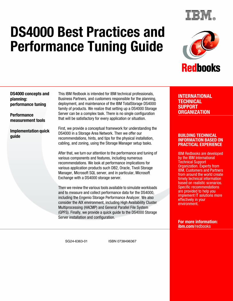
®
SG24-6363-01 ISBN 0738496367
INTERNATIONAL TECHNICALSUPPORTORGANIZATION
BUILDING TECHNICAL INFORMATION BASED ON PRACTICAL EXPERIENCE
IBM Redbooks are developed by the IBM International Technical Support Organization. Experts from IBM, Customers and Partners from around the world create timely technical information based on realistic scenarios. Specific recommendations are provided to help you implement IT solutions more effectively in your environment.
For more information:ibm.com/redbooks
DS4000 Best Practices and Performance Tuning Guide
DS4000 concepts and planning: performance tuning
Performance measurement tools
Implementation quick guide
This IBM Redbook is intended for IBM technical professionals, Business Partners, and customers responsible for the planning, deployment, and maintenance of the IBM TotalStorage DS4000 family of products. We realize that setting up a DS4000 Storage Server can be a complex task. There is no single configuration that will be satisfactory for every application or situation.
First, we provide a conceptual framework for understanding the DS4000 in a Storage Area Network. Then we offer our recommendations, hints, and tips for the physical installation, cabling, and zoning, using the Storage Manager setup tasks.
After that, we turn our attention to the performance and tuning of various components and features, including numerous recommendations. We look at performance implications for various application products such DB2, Oracle, Tivoli Storage Manager, Microsoft SQL server, and in particular, Microsoft Exchange with a DS4000 storage server.
Then we review the various tools available to simulate workloads and to measure and collect performance data for the DS4000, including the Engenio Storage Performance Analyzer. We also consider the AIX environment, including High Availability Cluster Multiprocessing (HACMP) and General Parallel File System (GPFS). Finally, we provide a quick guide to the DS4000 Storage Server installation and configuration.
Back cover
Related Documents


![IBM Storwize V3500img.zhilankeji.com/ibm/storwize_v3500_01.pdf · 2013-12-18 · IBM Storwize V7000 2010 年 10 ... V7000 Storwize V7000 [ Unified ] DS4000, DS5000, Storwize V7000](https://static.cupdf.com/doc/110x72/5f8da2e2ad21c4137b6552e2/ibm-storwize-2013-12-18-ibm-storwize-v7000-2010-10-v7000-storwize-v7000.jpg)

