1 3xtend/EINC L/.. Data Sheet TA200800 3 12/8/08 Data Sheet 3xtend/EINC L/.. Node Controller 3xtend/EINC L/.. Description The 3xtend/EINC L enables IQ networks running on the IQ system current loop Lan, Ethernet, and LONWORKS ® network to be integrated into a single network. It operates at the internetwork level, including the necessary support for WAN’s. It also provides virtual CNCs that allow supervisory or tool software running in PCs connected to the Ethernet network to connect to the BMS system. Operation on a LONWORKS network is achieved without the need for any LONWORKS network management. Features • Integration of IQ network on IQ system current loop Lan, Ethernet and LONWORKS network. • 10/100 BASE-T interface. • Eight virtual CNCs for PC connection using Ethernet. • Can span routers. • Metal enclosure for 230 version (not available in USA). • Network alarms available in 10 languages. • FLASH retains configured data during power fail (no battery required). • Integration of IQL controllers into IQ system. • Connection to LONWORKS network with IqlTool 2 using virtual CNC. • DHCP Enabled. Physical 24V version Front view with panels removed to expose terminals 1 2 3 4 5 6 7 8 9 10 Power Ethernet connector IQ system current loop connector Power LED Ethernet OK LED Current loop Lan LEDs (TX, RX, OK) M20 (¾”) conduit entry Rear cable entry Neoprene seal 3 point mounting holes 4 point mounting holes 227 mm (8.94”) 218 mm (8.58”) 60 mm (2.36”) SD socket Service button LON connector LON terminator link LON Service LED Address Switch LON OK LED

Welcome message from author
This document is posted to help you gain knowledge. Please leave a comment to let me know what you think about it! Share it to your friends and learn new things together.
Transcript

13xtend/EINC L/.. Data Sheet TA200800 3 12/8/08
Data Sheet
3xtend/EINC L/..Node Controller
3xtend/EINC L/..
Description
The 3xtend/EINC L enables IQ networks running on the IQ systemcurrent loop Lan, Ethernet, and LONWORKS® network to beintegrated into a single network. It operates at the internetworklevel, including the necessary support for WAN’s. It also providesvirtual CNCs that allow supervisory or tool software running inPCs connected to the Ethernet network to connect to the BMSsystem.
Operation on a LONWORKS network is achieved without the needfor any LONWORKS network management.
Features
• Integration of IQ network on IQ system current loop Lan,Ethernet and LONWORKS network.
• 10/100 BASE-T interface.• Eight virtual CNCs for PC connection using Ethernet.• Can span routers.• Metal enclosure for 230 version (not available in USA).• Network alarms available in 10 languages.• FLASH retains configured data during power fail (no battery required).• Integration of IQL controllers into IQ system.• Connection to LONWORKS network with IqlTool 2 using virtual
CNC.• DHCP Enabled.
Physical
24V version
Front view with panels removed to expose terminals
1 2 3 4 5 6 7 8 9 10
Power
Ethernetconnector
IQ system current loopconnector
PowerLED
Ethernet OKLED
CurrentloopLan LEDs(TX, RX,OK)
M20 (¾”) conduit entry
Rear cable entry Neoprene seal
3 point mounting holes
4 pointmountingholes
227 mm (8.94”)
218
mm
(8.
58”)
60 mm (2.36”)
SD socketService button
LONconnector
LON terminator link
LON ServiceLED
Address Switch
LON OKLED

2 3xtend/EINC L/.. Data Sheet TA200800 Issue 3 12/8/08
3xtend/EINC L/.. Data Sheet
Physical (Continued)
230V version (not available in USA)
� � �
� � � � � � � � � � � � � � � � �
� � �
� � � � �� � � � � � � � � � �
� � � � � � � � � � � � � �
� � � � � � � � � � � � � � � � �
� � � � �� � � � � � � � � � �� ! � � � " # $ %
� � � � � � �
� � � & � '
� � � � � � � � � � � � � � � � � �
� � � � � �
� �
� � � �
� � � � � � � � �
� � � � � � �
� � � � � � � � � �
� � � � � � �
� � � � � � � � � � � � � � � � � � � � � � � � � � � � � � � � � � � � � �
� �
� �
� �
� � �
� � � � � � � � � � � � � �
� � � � � � �
302 mm (11.89”) 60 mm (2.36”)
266
mm
(10
.47”
)
Transformer
24V terminals
Cable knockout
Ethernetconnector IQ system current loop connector
Power LED
Ethernet OK LED
Current loop Lan LEDs (TX, RX,OK)
SD socketService button
Input Powerterminals
LON terminator link
LON OK LEDAddress Switch
LON ServiceLED
LON connector
FUNCTIONALITYThe functionality of the 3xtend/EINC L can be split into system, hardware, and firmware sections:
SYSTEM
The 3xtend/EINC L acts as an interface between parts of an IQ network running over IQ system current loop, Ethernet, and LONWORKS network.It acts like an INC, but it enables Ethernet or LONWORKS network to be used to carry the internetwork. It also enables a current loop internetworkto be extended onto Ethernet or LONWORKS network. To enable this a 3xtend/EINC L’s current loop can operate in one of two modes:
INC modeInternetwork Extension mode.
The mode of operation is determined by the address set on its address switch. When set to a value less than 100 the current loop willoperate in INC mode when set to a value greater than or equal to 100 the current loop will operate in Internetwork Extension mode.
Note that it is recommended that the LONWORKS network is not used where a high level of communication traffic is expected, e.g.joining internetworks or where there are many IQ System devices on many IQ System Lans being accessed across an internetworkrouted through the LONWORKS network. An alternative topology should be used, such as an Ethernet internetwork.

33xtend/EINC L/.. Data Sheet TA200800 Issue 3 Draft 12/8/08
Data Sheet 3xtend/EINC L/..
Lan(on current loop)
Internetwork(on current loop)
LINC
EINC
EINC
INC
Internetwork(on Ethernet)
Internetwork(on L W network)ON ORKS
Lan(on current loop)
3xtend/EINC LInternetwork(on Ethernet)
Internetwork(on L W network)ON ORKS
4 5 6
27 8 9
310 11 12
4
13 14 15
5
16 17 18
619 20 21
722 23 24
825 26 27
928 29 30
10+ 0+ 0 + 0 + 0 + 0 + 0+ 0+ 0+ 0
1 2 3
1+ 0
0 V24 V
24 V 34 35 36
12
37 38 39
13
40 41 42
14A
31 32 33P
11
43 44 45
15
46 47 48
16100-240 V
OK RXP 0 P 0 P 0P 0 P 0 P 0
EINC
( � � �
� � �
4 5 6
27 8 9
310 11 12
4
13 14 15
5
16 17 18
6
19 20 21
7
22 23 24
825 26 27
928 29 30
10+ 0+ 0 + 0 + 0 + 0 + 0+ 0+ 0+ 0
1 2 3
1+ 0
0 V24 V
24 V 34 35 36
12
37 38 39
13
40 41 42
14A
31 32 33P
11
43 44 45
15
46 47 48
16100-240 V
OK RXP 0 P 0 P 0P 0 P 0 P 0
� � �
4 5 6
27 8 9
310 11 12
4
13 14 15
5
16 17 18
619 20 21
722 23 24
825 26 27
928 29 30
10+ 0+ 0 + 0 + 0 + 0 + 0+ 0+ 0+ 0
1 2 3
1+ 0
0 V24 V
24 V 34 35 36
12
37 38 39
13
40 41 42
14A
31 32 33P
11
43 44 45
15
46 47 48
16100-240 V
OK RXP 0 P 0 P 0P 0 P 0 P 0
� � �
4 5 6
27 8 9
310 11 12
4
13 14 15
5
16 17 18
6
19 20 21
7
22 23 24
825 26 27
928 29 30
10+ 0+ 0 + 0 + 0 + 0 + 0+ 0+ 0+ 0
1 2 3
1+ 0
0 V24 V
24 V 34 35 36
12
37 38 39
13
40 41 42
14A
31 32 33P
11
43 44 45
15
46 47 48
16100-240 V
OK RXP 0 P 0 P 0P 0 P 0 P 0
� � � � � ) � & *
( � + & & �
� �
, � � � - & � � � � � . /OK
Tx Rx
230 V1 2 3 4 5 6 83 4 5
7 9 10 1124 V 24V
AC24VAC
24VAC
OK
Tx Rx
230 V1 2 3 4 5 6 83 4 5
7 9 10 1124 V 24V
AC24VAC
24VAC
� � � �
� �
, � � ( � + & & � /
� �
, � � ( � + & & � /
� � & & � * � 0
, � � ( � + & & � /
L WNetworkON ORKS
Lan(on Current Loop)
OK
Tx Rx
230 V1 2 3 4 5 6 83 4 5
7 9 10 1124V 24V
AC
24V
AC
24V
AC
OK
Tx Rx
230 V1 2 3 4 5 6 83 4 5
7 9 10 1124V 24V
AC
24V
AC
24V
AC
IQ IQ
Lan(on LON)
Lan(on LON)
LINC
IQLIQL
IQLIQLInternetwork
(on LON)
System without 3xtend/EINC L Equivalent system with 3xtend/EINC L
In the diagram above the functions of the EINC, LINC, and INC arereplaced by the 3xtend/EINC L.
Note that when operating in this mode it is not possible to haveanother internetworking device (INC or another 3xtend/EINC L)on the IQ system current loop.
The 3xtend/EINC L will build an internetwork with other 3xtend/EINC Ls, EINCs, LINCs, IQ3s, IQLs, or IQViews connected to the sameEthernet network or LONWORKS network. Once these internetworks are complete they are joined together inside the 3xtend/EINC Lalong with the Lan on the current loop to form a single IQ network. The 3xtend/EINC L builds up a list of which Lans are connectedusing Ethernet, LONWORKS network or IQ system current loop and automatically routes messages to the correct network.
The LAN number of the Lan connected to the 3xtend/EINC L’s IQ system current loop is defined by the 3xtend/EINC L’s addressswitch and is known as the 3xtend/EINC L’s local Lan.
Note that only one internetwork device is allowed on a Lan therefore ensure that the 3xtend/EINC L’s LAN number is not used byanother INC type device.
The internetworks on Ethernet and LonWorks bus can be built in the normal way using other IQ system devices allowing the 3xtend/EINC Lto join together existing IQ networks. For example an IQ network on Ethernet consisting of two Lans of IQ3 controllers, an IQView, andan EINC with a current loop Lan, an IQ network on a LONWORKS network consisting of two Lans of IQL controllers, and an LINC with acurrent loop Lan, and a single Lan on the IQ system current loop can be joined together to form a single IQ network as shown.
Network 1 on Ethernet Network 2 on LONWORKS network
In the diagram above there are three Lans two on Ethernet, andone on the IQ system current loop connected to Ethernet usingthe EINC. These Lans are joined by an internetwork on Ethernet.
In the diagram above there are three Lans two on the LONWORKSnetwork, and one on the IQ system current loop connected to aLONWORKS network using the LINC. These Lans are joined by aninternetwork running on a LONWORKS network.
INC Mode
When operating in INC mode it enables an internetwork running on an Ethernet network, an internetwork running on a LonWorksbus and a Lan running on a current loop network to be joined together to form a single IQ network as shown below.

4 3xtend/EINC L/.. Data Sheet TA200800 Issue 3 12/8/08
3xtend/EINC L/.. Data Sheet
INC Mode (Continued)
Network 3 on IQ system current loop
� �
, � � � - & � � � � � . /OK
Tx Rx
230 V1 2 3 4 5 6 83 4 5
7 9 10 1124 V 24V
AC24VAC
24VAC
OK
Tx Rx
230 V1 2 3 4 5 6 83 4 5
7 9 10 1124 V 24V
AC24VAC
24VAC
� � � �
4 5 64 5 6
2
7 8 97 8 9
3
10 11 1210 11 12
4
13 14 1513 14 15
5
16 17 1816 17 18
6
19 20 2119 20 21
7
22 23 2422 23 24
8
25 26 2725 26 27
9
28 29 3028 29 30
10+ 0+ 0+ 0+ 0 + 0+ 0 + 0+ 0 + 0+ 0 + 0+ 0+ 0+ 0+ 0+ 0+ 0+ 0
1 2 31 2 3
1+
0V
24V
24V
34 35 3634 35 36
12
37 38 3937 38 39
13
40 41 4240 41 42
14A
31 32 3331 32 33P
11
43 44 4543 44 45
15
46 47 4846 47 48
16100-240 V100-240 V
OK RXOK RX
P 0 P 0 P 0P 0 P 0 P 0
EINC
EINC
IQ3
4 5 64 5 6
2
7 8 97 8 9
3
10 11 1210 11 12
4
13 14 1513 14 15
5
16 17 1816 17 18
6
19 20 2119 20 21
7
22 23 2422 23 24
8
25 26 2725 26 27
9
28 29 3028 29 30
10+ 0+ 0+ 0+ 0 + 0+ 0 + 0+ 0 + 0+ 0 + 0+ 0+ 0+ 0+ 0+ 0+ 0+ 0
1 2 31 2 3
1+
0V
24V
24V
34 35 3634 35 36
12
37 38 3937 38 39
13
40 41 4240 41 42
14A
31 32 3331 32 33P
11
43 44 4543 44 45
15
46 47 4846 47 48
16100-240 V100-240 V
OK RXOK RX
P 0 P 0 P 0P 0 P 0 P 0
IQ3
IQView
Ethernet
Lan(on Current Loop)
OK
Tx Rx
230 V1 2 3 4 5 6 83 4 5
7 9 10 1124V 24V
AC
24V
AC
24V
AC
OK
Tx Rx
230 V1 2 3 4 5 6 83 4 5
7 9 10 1124V 24V
AC
24V
AC
24V
AC
IQ IQ
Lan(on Ethernet)
Lan(on Ethernet)
Lan(on Current Loop)
OK
Tx Rx
230 V1 2 3 4 5 6 83 4 5
7 9 10 1124V 24V
AC
24V
AC
24V
AC
OK
Tx Rx
230 V1 2 3 4 5 6 83 4 5
7 9 10 1124V 24V
AC
24V
AC
24V
AC
IQ
IQ
L W networkON ORKS
Lan(on Current Loop)
OK
Tx Rx
230 V1 2 3 4 5 6 83 4 5
7 9 10 1124V 24V
AC
24V
AC
24V
AC
OK
Tx Rx
230 V1 2 3 4 5 6 83 4 5
7 9 10 1124V 24V
AC
24V
AC
24V
AC
IQ IQ
Lan(on LON)
Lan(on LON)
LINC
IQLIQL
IQLIQL
EINC/LInternetwork
(on LON)Internetwork(on Ethernet)
Internetwork(inside
3xtend/EINC L)
3xtend/EINC L
CNC3CNC2CNC1
3xtend/EINC L's Local Lan
INC
CNC4CNC7CNC6CNC5
CNC8
OK
Tx Rx
230 V1 2 3 4 5 6 83 4 5
7 9 10 1124V 24V
AC24VAC
24VAC
IQ
OK
Tx Rx
230 V1 2 3 4 5 6 83 4 5
7 9 10 1124V 24V
AC24VAC
24VAC
IQ
126
Internetwork(on current loop)
Internetwork(on current loop) LINC
EINC
EINC
INC
Internetwork(on Ethernet)
Internetwork(on L W network)ON ORKS
Internetwork(on current loop)
3xtend/EINC LInternetwork(on Ethernet)
Internetwork(on L W network)ON ORKS
In the diagram left there is a single Lan on the IQ system currentloop,
Networks 1, 2, and 3 can be joined together using a 3xtend/EINC L as shown below.
In the diagram above networks 1, 2, and 3 are joined together by a 3xtend/EINC L. The 3xtend/EINC L is connected to the Ethernetnetwork, the LONWORKS network, and the IQ system current loop. The 3xtend/EINC L connects to both the Ethernet and LONWORKS
network internetworks, and the IQ system current loop Lan joining them together as a single IQ network of 7 Lans on Ethernet,LONWORKS network, and the IQ system current loop. The Lans are linked together by an internetwork that is also running on Ethernet,and LONWORKS network.
In this mode the 3xtend/EINC L’s Local Lan’s Lan number isdefined by the address switch. This Lan will consist of thedevice connected to the IQ system current loop to which the3xtend/EINC L is connected; it will also contain the 3xtend/EINCL’s virtual CNCs, plus the 3xtend/EINC L itself, which always hasaddress 126.
Internetwork Extension Mode
When operating in internetwork extension mode the 3xtend/EINC L enables an internetwork running on an Ethernet network, aninternetwork running on a LONWORKS network and a internetwork running on an IQ system current loop network to be joined togetherto form a single IQ network as shown below.
System without 3xtend/EINC LEquivalent system with 3xtend/EINC L
In the diagram above the functions of the EINC, LINC, and INC arereplaced by the 3xtend/EINC L.
The 3xtend/EINC L will build an internetwork with other 3xtend/EINC Ls, EINCs, LINCs, INCs, IQ3s, IQLs, or IQViews connectedto the same IQ system current loop, Ethernet network or LONWORKS
network. Once these internetworks are complete they are joined together inside the 3xtend/EINC L. 3xtend/EINC L builds a list ofwhich devices are connected using Ethernet, LONWORKS network or IQ system current loop and routes messages to the correctnetwork.

53xtend/EINC L/.. Data Sheet TA200800 Issue 3 Draft 12/8/08
Data Sheet 3xtend/EINC L/..
L WNetworkON ORKS
Lan(on Current Loop)
OK
Tx Rx
230 V1 2 3 4 5 6 83 4 5
7 9 10 1124V 24V
AC
24V
AC
24V
AC
OK
Tx Rx
230 V1 2 3 4 5 6 83 4 5
7 9 10 1124V 24V
AC
24V
AC
24V
AC
IQ IQ
Lan(on LON)
Lan(on LON)
LINC
IQLIQL
IQLIQLInternetwork
(on LON)
4 5 6
27 8 9
310 11 12
4
13 14 15
5
16 17 18
619 20 21
722 23 24
825 26 27
928 29 30
10+ 0+ 0 + 0 + 0 + 0 + 0+ 0+ 0+ 0
1 2 3
1+ 0
0 V24 V
24 V 34 35 36
12
37 38 39
13
40 41 42
14A
31 32 33P
11
43 44 45
15
46 47 48
16100-240 V
OK RXP 0 P 0 P 0P 0 P 0 P 0
EINC
( � � �
� � �
4 5 6
27 8 9
310 11 12
4
13 14 15
5
16 17 18
6
19 20 21
7
22 23 24
825 26 27
928 29 30
10+ 0+ 0 + 0 + 0 + 0 + 0+ 0+ 0+ 0
1 2 3
1+ 0
0 V24 V
24 V 34 35 36
12
37 38 39
13
40 41 42
14A
31 32 33P
11
43 44 45
15
46 47 48
16100-240 V
OK RXP 0 P 0 P 0P 0 P 0 P 0
� � �
4 5 6
27 8 9
310 11 12
4
13 14 15
5
16 17 18
619 20 21
722 23 24
825 26 27
928 29 30
10+ 0+ 0 + 0 + 0 + 0 + 0+ 0+ 0+ 0
1 2 3
1+ 0
0 V24 V
24 V 34 35 36
12
37 38 39
13
40 41 42
14A
31 32 33P
11
43 44 45
15
46 47 48
16100-240 V
OK RXP 0 P 0 P 0P 0 P 0 P 0
� � �
4 5 6
27 8 9
310 11 12
4
13 14 15
5
16 17 18
6
19 20 21
7
22 23 24
825 26 27
928 29 30
10+ 0+ 0 + 0 + 0 + 0 + 0+ 0+ 0+ 0
1 2 3
1+ 0
0 V24 V
24 V 34 35 36
12
37 38 39
13
40 41 42
14A
31 32 33P
11
43 44 45
15
46 47 48
16100-240 V
OK RXP 0 P 0 P 0P 0 P 0 P 0
� � � � � ) � & *
( � + & & �
� �
, � � � - & � � � � � . /OK
Tx Rx
230 V1 2 3 4 5 6 83 4 5
7 9 10 1124 V 24V
AC24VAC
24VAC
OK
Tx Rx
230 V1 2 3 4 5 6 83 4 5
7 9 10 1124 V 24V
AC24VAC
24VAC
� � � �
� �
, � � ( � + & & � /
� �
, � � ( � + & & � /
� � & & � * � 0
, � � ( � + & & � /
� �
, � � � - & � � � � � . /OK
Tx Rx
230 V1 2 3 4 5 6 83 4 5
7 9 10 1124 V 24V
AC24VAC
24VAC
OK
Tx Rx
230 V1 2 3 4 5 6 83 4 5
7 9 10 1124 V 24V
AC24VAC
24VAC
� � � �
� �
, � � � - & � � � � � . /OK
Tx Rx
230 V1 2 3 4 5 6 83 4 5
7 9 10 1124 V 24V
AC24VAC
24VAC
OK
Tx Rx
230 V1 2 3 4 5 6 83 4 5
7 9 10 1124 V 24V
AC24VAC
24VAC
� � � �
� � �
� � �
� � & & � * � 0
, � � � - & � � � � � . /
4 5 64 5 6
2
7 8 97 8 9
3
10 11 1210 11 12
4
13 14 1513 14 15
5
16 17 1816 17 18
6
19 20 2119 20 21
7
22 23 2422 23 24
8
25 26 2725 26 27
9
28 29 3028 29 30
10+ 0+ 0+ 0+ 0 + 0+ 0 + 0+ 0 + 0+ 0 + 0+ 0+ 0+ 0+ 0+ 0+ 0+ 0
1 2 31 2 3
1+
0V
24V
24V
34 35 3634 35 36
12
37 38 3937 38 39
13
40 41 4240 41 42
14A
31 32 3331 32 33P
11
43 44 4543 44 45
15
46 47 4846 47 48
16100-240 V100-240 V
OK RXOK RX
P 0 P 0 P 0P 0 P 0 P 0
EINC
EINC
IQ3
4 5 64 5 6
2
7 8 97 8 9
3
10 11 1210 11 12
4
13 14 1513 14 15
5
16 17 1816 17 18
6
19 20 2119 20 21
7
22 23 2422 23 24
8
25 26 2725 26 27
9
28 29 3028 29 30
10+ 0+ 0+ 0+ 0 + 0+ 0 + 0+ 0 + 0+ 0 + 0+ 0+ 0+ 0+ 0+ 0+ 0+ 0
1 2 31 2 3
1+
0V
24V
24V
34 35 3634 35 36
12
37 38 3937 38 39
13
40 41 4240 41 42
14A
31 32 3331 32 33P
11
43 44 4543 44 45
15
46 47 4846 47 48
16100-240 V100-240 V
OK RXOK RX
P 0 P 0 P 0P 0 P 0 P 0
IQ3
IQView
Ethernet
Lan(on Current Loop)
OK
Tx Rx
230 V1 2 3 4 5 6 83 4 5
7 9 10 1124V 24V
AC
24V
AC
24V
AC
OK
Tx Rx
230 V1 2 3 4 5 6 83 4 5
7 9 10 1124V 24V
AC
24V
AC
24V
AC
IQ IQ
Lan(on Ethernet)
Lan(on Ethernet)
L W networkON ORKS
Lan(on Current Loop)
OK
Tx Rx
230 V1 2 3 4 5 6 83 4 5
7 9 10 1124V 24V
AC
24V
AC
24V
AC
OK
Tx Rx
230 V1 2 3 4 5 6 83 4 5
7 9 10 1124V 24V
AC
24V
AC
24V
AC
IQ IQ
Lan(on LON)
Lan(on LON)
LINC
IQLIQL
IQLIQL
EINC/LInternetwork
(on LON)Internetwork(on Ethernet)
Internetwork(inside
3xtend/EINC L)
Lan(on Current Loop)
OK
Tx Rx
230 V1 2 3 4 5 6 83 4 5
7 9 10 1124V 24V
AC
24V
AC
24V
AC
OK
Tx Rx
230 V1 2 3 4 5 6 83 4 5
7 9 10 1124V 24V
AC
24V
AC
24V
AC
IQIQ
INC Lan(on Current Loop)
OK
Tx Rx
230 V1 2 3 4 5 6 83 4 5
7 9 10 1124V 24V
AC
24V
AC
24V
AC
OK
Tx Rx
230 V1 2 3 4 5 6 83 4 5
7 9 10 1124V 24V
AC
24V
AC
24V
AC
IQ
IQ
INC
Internetwork(on Current Loop)
3xtend/EINC L
CNC3CNC2CNC1
3xtend/EINC L's Local Lan
INC
CNC4CNC7CNC6CNC5
CNC8
126
Internetwork Extension Mode (Continued)
The internetworks are built in the normal way with other IQ system devices allowing the 3xtend/EINC L to join together existing IQ networks.For example an IQ network on Ethernet consisting of two Lans of IQ3 controllers, an IQView, and an EINC with a current loop Lan, anIQ network on a LONWORKS network consisting of two Lans of IQL controllers, and an LINC with a current loop Lan, and an IQ networkon the IQ system current loop consisting of two Lans of IQ controllers can be joined together to form a single IQ network as shown.
Network 1 on Ethernet Network 2 on LONWORKS network
In the diagram above there are three Lans two on Ethernet, andone on the IQ system current loop connected to Ethernet usingthe EINC. They are joined by an internetwork running on Ethernet.
In the diagram above there are three Lans two on a LONWORKS
network, and one on the IQ system current loop connected to aLONWORKS network using the LINC. They are joined by aninternetwork running on a LONWORKS network.
Network 3 on IQ system current loop
In the diagram left there are two Lans on the IQ system currentloop joined together by an internetwork also running on IQ systemcurrent loop.
Networks 1, 2, and 3 can be joined together using a 3xtend/EINC L as shown below.
In the diagram above networks 1, 2, and 3 are joined together by a 3xtend/EINC L. The 3xtend/EINC L is connected to the Ethernet network,the LONWORKS network, and the IQ system current loop Lan. The 3xtend/EINC L connects to the Ethernet, LONWORKS network, and IQsystem current loop internetworks joining them together as a single IQ network of 8 Lans on Ethernet, LONWORKS network, and the IQ systemcurrent loop all linked together by an internetwork that is also running on Ethernet, LONWORKS network, and the IQ system current loop.
When operating in this mode the 3xtend/EINC L’s Local Lan’s Lannumber is defined by the address switch. This Lan will containthe 3xtend/EINC L’s virtual CNCs, plus the 3xtend/EINC L itself,which always has address 126.
Note that only one internetwork device is allowed on a Lantherefore ensure that the 3xtend/EINC L’s LAN number is notused by another INC type device.

6 3xtend/EINC L/.. Data Sheet TA200800 Issue 3 12/8/08
3xtend/EINC L/.. Data Sheet
Virtual CNCs
The 3xtend/EINC L’s firmware incorporates eight virtual CNCs that enable the connection between a PC running supervisor/toolsoftware and the IQ network to be made over Ethernet to the virtual CNC. They also enable alarms generated from IQs or otherdevices to be transmitted to a PC running 963. In order to do this each of the virtual CNCs can act in on of two modes:
Supervisor modeAlarm mode
For a virtual CNC to operate, its CNC address must be set up using IPTool or in configuration mode. The virtual CNC is switched froma supervisor mode to alarm mode by setting up an alarm IP address or host name in the virtual CNC module. Once enabled the virtualCNCs appear to be located on the 3xtend/EINC L’s local Lan, and will respond to Lan mapping in this way.
3xtend/EINC L
CNC3CNC2CNC1
3xtend/EINC L's Local Lan
INC CNC4
CNC7CNC6CNC5 CNC8
Tempory EthernetConnection
963
IQ3
IQ3
Internetwork(on Ethernet)
Lan =21
EINCEINC
EINC
Ethernet
Lan =20
Address=22
3xtend/EINC L
Address=23
3xtend/EINC L
CNC3CNC2CNC1
3xtend/EINC L's Local Lan (Lan 20)
INC CNC4
CNC7CNC6CNC5 CNC8
Ethernet
Supervisor/Tool
24
Supervisor ModeThis enables the Ethernet network to be used as a connectionbetween a PC running supervisory or tool software and thevirtual CNC (rather than normal RS232, device to CNC, interface).The supervisor connects to the CNC by using the 3xtend/EINCL’s host name or IP address and the port address set up in the virtualCNC module making a permanent connection to the virtual CNC. Thisenables the supervisor/tool to communicate with devices on the IQnetwork, and for those devices to communicate with it.
The 963 can make a connection to the virtual CNC wheninformation is required, treating each connection as a separatesite. However, temporary connections will not allow the virtualCNC to send alarms back to the supervisor; instead a virtual CNCin alarm mode must be used.
When IqlTool 2 connects to the a virtual CNC in supervisor modeIqlTool 2 detects that the virtual CNC is capable of communicationswith devices on a LONWORKS network enabling IqlTool 2 to connectto the LONWORKS network over an Ethernet network.
Connection to virtual CNC
In the diagram above the supervisor/tool connects to the 3xtend/EINC L virtual CNC2 over Ethernet, and will have will have a Lanaddress of 20 and a network address of 24 on the IQ network.
Alarm ModeThe Alarm mode of a virtual CNC enables alarms generated fromIQs or other devices to be transmitted to a PC running 962 v3 orgreater or 963 connected to the Ethernet where the connectionto the virtual CNC is of a temporary nature. An IQ can send itsalarms to the virtual CNC using normal Lan/device addressing,and the virtual CNC will forward the alarms to the PC using thePort Address and the Alarm host name/IP address, specified inthe virtual CNC. The 963 listens for alarms on the specified port,and retrieves the site identities, Lan numbers, and deviceaddresses of any alarms it receives so that it can process themfurther.
In the diagram right the 963 is able to connect to the site on whichthe 3xtend/EINC L is situated, using a temporary connection tovirtual CNC 1 which is in supervisor mode. Virtual CNC 2 isoperating in alarm mode and set to forward alarms it receivesto the IP address of the 963.
Connection to virtual CNC with alarms sent by virtual CNC in alarmmode.
Building Internetworks On Ethernet
The 3xtend/EINC L will build an internetwork with EINCs, IQ3 controllers, IQViews, NXIPs, and other 3xtend/EINC L that are connectedto the Ethernet network.
If there is more than one EINC, IQ3, 3xtend/EINC L, or IQView onthe same segment of the Ethernet network (no routers betweenthem) and they use the same UDP port they will automaticallyform a single internetwork as shown right. If IQ3s, NXIPs, andIQViews have formed Lans the device with the lowest IP addresswill assume INC functionality and will be included in theinternetwork. In the diagram right the 3xtend/EINC L, IQ3 controllersand the EINC are on the same network segment and the IQ3controllers have different Lan numbers. Therefore they form aninternetwork consisting of Lan 20, Lan 21, Lan 22, and Lan 23.
When there are routers on the Ethernet network and it is requiredfor the internetwork to be built across routers an IQ systemEthernet device must be installed on either side of the router andbe configured to span the routers. In the diagram right there isa router with EINCs and IQ3 controllers on the Ethernet network.

73xtend/EINC L/.. Data Sheet TA200800 Issue 3 Draft 12/8/08
Data Sheet 3xtend/EINC L/..
IQ3
IQ3
Internetwork(on Ethernet)
Lan =21
EINC
EINC
Ethernet
Lan =20
Address=22
3xtend/EINC L
Address=23
Router Internetwork(on Ethernet)
IQ3
IQ3
Internetwork(on Ethernet)
Lan =21
EINCEINC
EINC
Ethernet
Lan =20
Address=22
3xtend/EINC L
Address=23
Router Internetwork(on Ethernet)
LINC
IQL1
Lan 6Address 21
Lan 6Address 22
IQL3
Lan 5Address 21
3xtend/EINC L
Lan 1
Lan 7IQL2
Internetwork
(on L W network)ON ORKS L WNetworkON ORKS
Building Internetworks On Ethernet (Continued)
If none of the devices have their remote devices table setup theywill be unable to build an internetwork across the routers, and willconstruct two separate internetworks as shown right. This iseffectively two separate sites.
For the sites to combine, the remote devices table must be setup in each device on the system. The remote devices table mustcontain the details of two devices in the network from each othersubnet and be set up in every device on the local subnet. Forincreased reliability, details of additional devices should also beset up. In the example all the devices have had their remotedevices table setup. This allows the two sites to combine to formone single site as shown right.
The setting up of the table in more than one device across routers is facilitated by the ‘uPdatelist’ configuration module. This enablesthe remote devices table from the 3xtend/EINC L to be copied to all the 3xtend/EINC L and EINCs in the table.
UDP PortThe UDP (User Datagram Protocol) port number defines the Ethernet port used by the 3xtend/EINC L to send messages to otherIQ system Ethernet devices. To construct an internetwork, the devices must be on the same subnet (unless set up to span routers),and must use the same UDP port. If the user is restricted to using one subnet, but wishes to have separate sites on that subnet(i.e. more than one internetwork), then he can set different UDP port numbers for the groups of IQ system Ethernet devices in thedifferent internetworks.
Building Internetworks on a LONWORKS network
The 3xtend/EINC L will build an internetwork with LINCs, IQL controllers, and other 3xtend/EINC L that are connected to the LONWORKSnetwork.
If there is more than one LINC, IQL, 3xtend/EINC L, on the LONWORKSnetwork they will automatically form a single internetwork asshown right. If IQLs have formed Lans the device with the lowestaddress will assume INC functionality and will be included in theinternetwork. In the diagram right the 3xtend/EINC L, the IQLcontrollers, and LINC are on the same network segment. IQL 1and 2 have the same Lan address and form a Lan. IQL3, and IQL1have the lowest address on their Lans and assume INCfunctionality and will build an internetwork with the 3xtend/EINCL, and LINC consisting of Lan 1, Lan 5, Lan 6, and Lan 7.
Note that 3xtend/EINC L is not compatible with LONCs. The LONC must be bound on a LONWORKS network, and 3xtend/EINC Lcannot be bound, an EINC and LINC must be used instead.
IQ system Network on a LONWORKS network - Rules
The maximum number of nodes allowed on an FTT LONWORKS network segment (i.e. between routers) is 64 (including any routernodes). The recommended maximum number of nodes on a Lan is 40.
Connection to Network on a LONWORKS network using a Virtual CNC
When IqlTool 2 connects to a virtual CNC in supervisor mode IqlTool 2 detects that the virtual CNC is capable of communicationswith devices on a LONWORKS network. This enables IqlTool 2 to connect to the network on the LONWORKS network over an Ethernetnetwork without the need for an LCI. If any of the 3xtend/EINC L’s virtual CNCs are connected to by IqlTool 2 the address modulesvlci in use parameter is set to Yes. Only one virtual CNC can be connected in this way at a time.

8 3xtend/EINC L/.. Data Sheet TA200800 Issue 3 12/8/08
3xtend/EINC L/.. Data Sheet
Ethernet Addressing
The 3xtend/EINC L’s Ethernet addressing information can be set up automatically (automatic addressing) or manually (manualaddressing). The default mode of operation is automatic addressing enabling the 3xtend/EINC L to be easily set up.
Note that when setting up the Ethernet addressing ensure that there is only one subnet on a network segment.
Automatic AddressingThe 3xtend/EINC L is able to operate on an Ethernet system where the IP addressing information (IP address, subnet mask, defaultrouter, and WINS Server) are automatically allocated by a Dynamic Host Configuration Protocol (DHCP) server or the IP addressis automatically negotiated with other devices. This means that the IP address is not fixed.
When in auto addressing mode the 3xtend/EINC L obtains IP addressing information from a DHCP server. If there is no DHCP serveror the DHCP server fails the 3xtend/EINC L enters link/local mode where it auto-negotiates its IP address with other devices on itsEthernet segment. There may be some time delay between DHCP server failure and the 3xtend/EINC L entering link/local mode asit will only prompt the DHCP server after its lease has expired which may be a long time.
When in link/local mode IP addresses start at 169.254.0.0 with subnet mask of 255.255.0.0; ensuring all devices in link/local modeare on the same subnet, the default router, and WINS server address remain at their last settings. Any devices wanting to communicatewith them using IP addressing must be on this subnet.
Fixing the 3xtend/EINC L’s address on a DHCP controlledSystem: It is possible for the 3xtend/EINC L to operate in a DHCPregime with a fixed IP address by setting up the DHCP server so thatit always gives the 3xtend/EINC L the same IP address. An alternativeis to set the 3xtend/EINC L to use manual addressing and set its IPaddress outside the range of the DHCP server.
Connecting to an automatically addressed 3xtend/EINCL: Because the 3xtend/EINC L’s IP address may not remain thesame any connection to it over Ethernet, e.g. to a virtual CNC,must use a host name. For more details see ‘Host name’ below.
Note that if any communication using a host name crosses arouter(s), then a WINS server address must be set up.
Crossing Routers if DHCP is operating: In the DHCP regime,if the internetwork is to be built across a router(s), the devicesin the remote devices table must be specified using their hostnames and subnet mask. This will enable the IP addresses to beobtained from the WINS servers. The remote devices table mustcontain the details of two devices in the network from each othersubnet and be set up in every device on the local subnet. Forincreased reliability, details of additional devices should also beset up.
Manual AddressingThe 3xtend/EINC L can operate on an Ethernet system where the IP addressing information (IP address, subnet mask, default router,and WINS Server) are specified manually (i.e. the IP address is fixed). This is done using IPTool.
Connecting to a manually addressed 3xtend/EINC L:Connection to a 3xtend/EINC L over Ethernet, e.g. to a virtual CNC,can be made using either the host name or IP address. For moredetails see ‘Host names’ below.
Note that If any communication using a host name crosses arouter(s), then a WINS server address must be set up.
Crossing Routers: If the internetwork is to be built across arouter(s), the devices in the remote devices table can be specifiedusing their host names and subnet mask, or IP address andsubnet mask. The remote devices table must contain the detailsof the two devices with the lowest IP address in the network fromeach other subnet and be set up in every device on the localsubnet. For increased reliability, details of additional devicesshould also be set up.
Use across routers: If the connection is to be across routersa Windows Internet Naming Service (WINS) server must be usedto enable the device connecting to the 3xtend/EINC L to obtainthe EINC L’s IP address. Each device must be set up with the IPaddress of the WINS server. The 3xtend/EINC L sends its hostname to the WINS server on power up. Devices wishing tocommunicate with 3xtend/EINC L send the host name to the WINSserver which returns the associated IP address.
If a WINS server is not present the host name can only be usedover the local segment (i.e. not across routers).
Use in a DHCP regime: Because the 3xtend/EINC L’s IP addressmay not remain the same the host name must be used to connectto the 3xtend/EINC L when automatic addressing is being used.
Communication across the Internet: If connection to 3xtend/EINC L is to be made using the Internet then the firewall either hasto be able to use the host name, or the 3xtend/EINC L’s IP addressmust be fixed.
Remote Devices Table: The 3xtend/EINC L allows the addressof remote devices to be specified using host names.
Link/local Default Operation3xtend/EINC L, IQ3 controllers, and IQView are set to automatic IP addressing by default. If a group of these devices are connectedtogether on an Ethernet segment (without DHCP, WINS servers) they will power up in link/local and auto-negotiate their IP addresses.If they have been set up with device addresses and Lan numbers they will construct an IQ system network. A supervisor or systemtool running on a PC on the same segment will be able to communicate with them using host names (if the PC is set up forauto-addressing). Such a system cannot form a network across a router; this would require the setting up of DHCP and WINS serversand the remote devices table.
Host names
The 3xtend/EINC L has an additional addressing parameter, Host name, which provides a user friendly method of accessing the3xtend/EINC L e.g. connecting to a virtual CNC, or building an internetwork across routers in a DHCP regime. The host name defaultsto TREND_xx_yy_zz where xx, yy and zz are the last 3 groups of number in the 3xtend/EINC L’s MAC address.

93xtend/EINC L/.. Data Sheet TA200800 Issue 3 Draft 12/8/08
Data Sheet 3xtend/EINC L/..
HARDWARE
Box: There are two mechanical versions of the 3xtend/EINC L: the 24V unit, and the 230V unit.
The 24V unit (/24) has a snap on cover which can be levered off to reveal the labeled terminal cover. This can be unscrewed toexpose the terminals, LEDs, and service button. The Power/Alarm LED (blue) can be seen externally with the covers in place. Thereare two M20 (or ¾”) conduit holes fitted with plastic bungs in the base of the box for cable entry and a rear rectangular aperturefor rear cable entry surrounded by a neoprene seal.
170 mm (6.69”)
126 mm (4.96”)
75 mm(2.95”)
196
mm
(3.7
8”)Length depends on
screw headprojection andscrew type
3 pointmounting
Ramped keyhole
4 pointmounting
255 mm (10”)
Length depends on screw headprojection and screw type
Ramped keyhole
The unit is either 3 point mounting (e.g. for mounting to a wall)or 4 point mounting (e.g. for mounting on a panel). The 3 holemounting method uses M4, 5, 6 or No. 10 or 12 screws. A rampedkeyhole slot in the top back centre of the unit slips over a screwhead, and as the unit is lowered the unit clamps onto the wallcreating a seal around the rear aperture. The two lower mountingholes can be used to spot their positions. The 4 hole mountingmethod uses 4 off M4 x 16 mm screws; this gives a maximumpanel thickness of 10 mm (0.39”). A template provided is only foruse for 4 hole mounting.
The 230V version (/230) is supplied in metal box suitable for wall mounting. The box can be opened to expose the terminals, LEDs,and service button. There are knockouts for M20 (or ¾”) conduit holes in the sides and base of the box.
The unit is 3 point mounting (e.g. for mounting to a wall). The 3hole mounting method uses M4, 5, 6 or No. 10 or 12 screws; aramped keyhole slot in the top back centre of the unit slips overa screw head, and as the unit is lowered the unit clamps ontothe wall. The two lower mounting holes can be used to spot theirpositions.
Power: The 3xtend/EINC L is available in two different power versions 24V and 230V.
The 24V version requires 24 Vac, 50/60 Hz, or 28 to 36 Vdc. Themaximum consumption is 8 VA. This power level cannot beprovided from an IQ controller’s auxiliary power output, so separateinput power supply unit is required.
A 230 V/24 Vac, 24 VA, transformer is available (ACC/24VAC).This is a sealed unit with two mounting lugs; it has an isolated24 Vac output and an additional earth (ground) lead connectedthrough from the input for earthing (grounding) the 3xtend/EINCL. A general purpose 24 Vac transformer may be used providingit is rated at 24VA or greater. Note that some transformers (asin typical plant room installations) are earthed (grounded) onone side of the secondary; therefore care must be taken toensure that the earthed (grounded) side of the transformersecondary is connected to the middle terminal of the 3xtend/EINC L’s power connector. The PSR/230/24-2.5 DIN rail mountingDC power supply unit may be used, but its output voltage levelmust be adjusted for maximum volts (28 Vdc).
The 230V version (/230) (not available in USA) requires 230 Vacinput power at 50 or 60 Hz. The maximum consumption is 8 VA.
Note that a switch or circuit breaker (230 Vac, 1 A) must beincluded in the input power to the unit and in close proximity toit, and it must be clearly marked as the disconnecting devicefor the unit.
Fusing: On both versions the PCB is protected by a 6.3 A fast-blowfuse. This protects the 3xtend/EINC L board from drawing excessivecurrent. If it blows the unit should be returned to the supplier for repair.
The /230 version is also protected by a 125 mA fuse before thetransformer, if necessary this fuse can be replaced.
Connectors: Two part connectors are used throughout to facilitatewiring.
Data Backup: Configuration data is stored in non-volatile memory(Flash).
Address Switch: The 3xtend/EINC L’s device address on thelocal Lan is set to 126 (hard coded); and its Lan number (1, 4 to9, 11 to 99) is selected by the address switch poles 1 to 7. It mustbe set to a Lan number unique on the internetwork and cannotbe the same as any IQ3 Lan number. An address setting <100identifies the mode of operation as current loop Lan/Ethernetinternetwork whereas =>100 identifies the mode of operation ascurrent loop internetwork/Ethernet internetwork.
Baud Rate Switch: The baud rate on the IQ system current loopnetwork is set by address/baud rate switch poles 8 to 10. It mustbe set to match other nodes on the Lan/internetwork. It may beset to 9k6, or 19k2 baud. It may also be set to 38k4 baud if thecurrent loop is connecting an internetwork.
IQ system Current Loop Network: The network terminalsfacilitate connection of 2 wire cables. The standard IQ systemcurrent loop features are included (TX, RX, and network OKindicators, bypass relay, and network alarm generation). If the IQsystem current loop is not to be connected (i.e. the unit is to onlyinterface between Ethernet and LonWorks bus) a loop backconnector must be fitted.
IQ system Current Loop Network bypass relay: In order thatthe current loop Lan continues to operate if the 3xtend/EINC Lfails, a set of node bypass relays is fitted to maintain networkintegrity in the event failure of the node’s power supply, or failureof the node itself. The bypassing of a node will be recognised bythe downstream node, and reported as a Lan Changed alarm.

10 3xtend/EINC L/.. Data Sheet TA200800 Issue 3 12/8/08
3xtend/EINC L/.. Data Sheet
HARDWARE (Continued)
Ethernet Network: The Ethernet port uses an RJ45 connector,and requires the specification of IP address, subnet mask, anddefault router. If required this information can be obtain from aDHCP server.
Ethernet Transceivers: The 3xtend/EINC L uses the 10/100BASE-T. The 100 BASE-T network uses twisted pair cable (toIEEE 802.3) and the 3xtend/EINC L can run up to 100 Mbps. Themaximum distance between the node and the hub is 100 m (109yds). The 3xtend/EINC L should be connected to the hub usingCat 5e unshielded or shielded (UTP or FTP) cable and RJ45plugs (shielded or unshielded appropriate to the cable).
SD Card: The 3xtend/EINC L has an SD card socket that will takean SD/MMC card (Secure digital/Multimedia card). This can beused for upgrades. Firmware upgrades will be supplied as a filealong with a utility to write it onto an SD card from a PC.
LONWORKS network: The LONWORKS network port uses 2 partconnectors with screw terminals for 0.5 to 2.5 mm2 cross sectionarea (14 to 20 AWG) cable.
LONWORKS network Transceivers: The integral LONWORKSnetwork transceiver uses FTT (or LPT) allows the use of freebus topology enabling star, bus, or loop wiring. It simplifiesinstallation and facilitates network expansion. The bus uses twowires (twisted pair) which are polarity independent with noneed for screen. The FTT runs at 78 k baud. The FTT LONWORKS
network may already be present in a building, so the IQ systemis able to make use of an existing building bus and hence reduceinstallation cost.
LONWORKS network Terminator Link: The LONWORKS network terminatorlink enables the LONWORKS network to be terminated. It can be set to oneof two positions, OFF, or Free. When set to OFF there is no terminationand the network must be terminated elsewhere. When set to Free thenetwork is terminated at that point with a 50Ω termination.
RS232 Port: An RS232 port is fitted for future use only, but iscurrently not used. Connections should not be made to this port.
Caution the unit MUST NOT be powered using the RS232port.
USB Port: A USB port is fitted for future use. Connections shouldnot be made to this port.
Reset: Setting both the address and baud rate switches to zero for more than 3 seconds with power applied will reset theconfiguration parameters to default values. Defaults are:
Address module (see list in firmware section)User module (clear)Router (clear)Virtual CNCs (clear)Remote EINCs (clear)
IndicatorsThe 3xtend/EINC L has 9 LED indicators.
EthernetOK :(green) ON if the 3xtend/EINC L has successfully
communicated with at least one other IQ systemdevice on the Ethernet. ON if internetwork on Ethernethas been constructed. OFF if 3xtend/EINC L alone(e.g. using virtual CNCs only).
Link :(green) ON if the 3xtend/EINC L has a good Ethernetconnection. If OFF it indicates a faulty Ethernetconnection.
Data :(yellow) Flashes when a package of data is beingreceived from the Ethernet network.
LONWORKS networkLON OK :(green) Flashes every 24s while the
internetwork on the LonWorks bus is being builtafter which it stays on indicating that the 3xtend/EINC L has successfully communicated with atleast one other IQ system device on the LonWorksbus. Although the virtual Lans of IQLs will buildin about 30s, it takes up to about 2½ minutes untilthe virtual internetwork on the LONWORKS networkis completed after a LONWORKS network change.
LON Service :(yellow) Flashes when service button ispressed.
Power :(blue) This LED is normally ON to indicate that thepower is connected. If OFF it indicates a power failureor processor problem. A slow double pulse indicatesthat an IP address has not been established. Thisoccurs briefly on startup when using a DHCP serverof for a more prolonged period if in automaticaddressing mode without a DHCP server.
Current Loop networkTX :(yellow) Indicates current flowing from the 3xtend/
EINC L current loop network transmitter (normallyON). If OFF indicates open circuit.
RX :(yellow) Indicates current flowing into the 3xtend/EINC L current loop network receiver (normally ON).If OFF indicates open circuit or short circuit.
OK :(green) This indicates that the 3xtend/EINC L is ableto send and receive messages on the current loopnetwork (normally ON). Flashes when prohibitedaddress switch setting (0, 2, 3, >119). When OFF itindicates a LAN BROKEN condition exists on thenetwork (e.g. baud rate fault). The LED will flashintermittently as it tries to communicate.

113xtend/EINC L/.. Data Sheet TA200800 Issue 3 Draft 12/8/08
Data Sheet 3xtend/EINC L/..
FIRMWARE
The 3xtend/EINC L’s firmware consists of a number of configuration modules (see table below) similar to the ones used in IQcontrollers that enable 3xtend/EINC L’s operation to be specified. These modules need to be set up as required before the 3xtend/EINC L will operate correctly.
The initial configuration is best done using IPTool over Ethernet. This allows the configuration of the IP address, subnet mask, UDPport, Lan and network address, default router, virtual CNCs, and the remote devices table. The configuration of other moduleparameters must be done using the 3xtend/EINC L’s configuration mode which provides access to all of the 3xtend/EINC L’sparameters. Configuration mode is a built-in feature enabling the modules to be setup using the network (including across theinternetwork), using any IQ system configuration utility.
When accessing the 3xtend/EINC L with IP Tool it can be identified from the list of devices by its MAC address. The 3xtend/EINCL can be accessed in configuration mode using any IQ system configuration utility connected to the IQ network. This connectioncan be made using Ethernet, or the current loop. A local PC may be connected using the Ethernet either by using an adjacent hub,or by direct connection using a standard Ethernet cable in conjunction with a crossover adapter (XCITE/XA) and then by using oneof the 3xtend/EINC L’s virtual CNCs. Once the configuration utility has connected to the IQ network the 3xtend/EINC L will be locatedfrom its local Lan at address 126 on Lan 0, and from the internetwork by device address 126 on its Lan number.
Configuration Mode
When a 3xtend/EINC L is accessed in configuration mode the top-level configuration mode menu is as follows:
Connecting to OS 126 Lan 63xtend/EINC LaddRess User virtualCncs TimeILoop Ethernet LonremoteEincs uPdatelist=?
Note that if Ethernet is not connected, the following warning is given:
*** WARNING - NO ETHERNET SIGNAL DETECTED ***
The required options are selected by entering the relevant upper case letter and pressing ENTER. If a value has been changedX+ENTER will confirm it and return to the top menu, whereas Q+ENTER will quit and return with the value unchanged. Configurationmode may be protected by a password that will stop any changes being made until a valid password is entered.
epyTeludoM stpmorPnoitarugifnoC reifitnedIeludoMsmmoCtxeT seludoMforebmuN
sserddA R R 1
pi-tenrehtE E 2n 1
nal-qI I 1n 1
klatnoL L 3n 1
sCNIEetomeR E )2nni(a/n 02
emiT T a/n 1
tsiletadpU P a/n 1
resU U U 1
CNClautriV C C 8

12 3xtend/EINC L/.. Data Sheet TA200800 Issue 3 12/8/08
3xtend/EINC L/.. Data Sheet
Address Module
The address module stores the 3xtend/EINC L’s addressing information and product specific non-network information. It has thefollowing parameters:
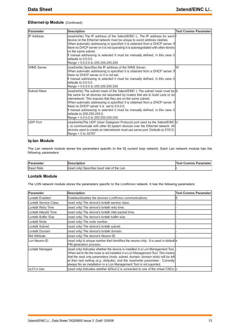
Ethernet-ip Module
The Ethernet-ipmodule stores the parameters specific to the Ethernet network. Each IP network module has the followingparameters:
retemaraP noitpircseD retemaraPsmmoCtxeTegaugnaLmralA ,hsinapS=1,hsilgnE=0.smralakrowtenehtrofdesuegaugnalehT)etirw/daer(
,nailatI=7,namreG=6,hsinaD=5,naigewroN=4,hsidewS=3,hsinniF=2)hsilgnE(0=tluafeD.hcnerF=9,eseugutroP=8
P
evilACNCvelbasiDsmralA
ehtybdetarenegsmraladaedeciveddna,enil-noecivedselbasid/selbanE.oN=tluafeD,delbasidsmrala=seY,oNroseY=egnaR.sCNClautriv
V
diegamihsalF .diegamihsalfs'ecivedehT)ylnodaer( -reifitnedI =tluafeD.naLehtyfitnediotdesulebalretcarahc04A)etirw/daer(
ehtnirebmunfospuorg3tsalehterazzdna,yy,xxerehW.zz_yy_xx_DNERT.sserddaCAMtenrehtE
.sretcarahc*?;{(\/ton-sretcarahcciremunahpla04
D
sserddAmralAkrowtenretnI ebnactI.smralakrowtenretnirofsserddaecivedtegratmralaehT)etirw/daer(spots0.)01dna,3,2sesserddagnidulcxe911ot1(sserddadilavynaottes
0=tluafeD.dettimsnartgniebsmralaeht
E
naLmralAkrowtenretnI tesebnactI.smralakrowtenretnirofrebmunnaLtegratmralaehT)etirw/daer(ehtspots0.)01dna,3,2sesserddagnidulcxe911ot1(sserddadilavynaot
0=tluafeD.dettimsnartgniebsmrala
T
sserddAmralAnaL tnerrucehtybdetarenegsmralarofsserddaecivedtegratmralaehT)etirw/daer(sserddadilavynaottesebnactI.naLasagnitarepositinehwkrowtenpoolgniebsmralaehtspots0.)01dna,3,2sesserddagnidulcxe911ot1(
0=tluafeD.dettimsnart
A
naLmralAnaL pooltnerrucehtybdetarenegsmralarofrebmunnaLtegratehT)etirw/daer(911ot1(sserddadilavynaebnactI.naLasagnitareponehwkrowten
.0=tluafeDdettimsnartgniebsmralaehtspots0.)01dna,3,2gnidulcxe
R
rebmuNnaL ehtotdetcennocpooltnerrucmetsysQIehtforebmunnaLehT)ylnodaer(otdesusitI.edomCNInignitarepositifiLCNIE/dnetx3ehtybkrowtenretnirofLCNIE/dnetx3ehtdna,CNClautrivs'LCNIE/dnetx3ehtsserddaegnaR.edomnoisnetxekrowtenretninignitareponehwsesoprupnoitarugifnoc
.1dna,3,2sesserddagnidulcxe911ot1(=eht,001<sisserddaehtfI.gnitteshctiwssserddaehtybdeficepssitIkrowtenretninisetarepoti001>=fidnaedomCNInisetarepoLCNIE/dnetx3
.edomnoisnetxe
n
edoCtcudorP .rebmunlairess'tinuehT)ylnodaer( -noisreV etaddna,eussimorp,epytecivedgniniatnocgnirtsretcarahc-52A)ylnodaer( C
retemaraP noitpircseD retemaraPsmmoCtxeTgnisserddA-pi-otuA .desusignisserddalaunamrocitamotuarehtehwseificepS)etirw/daer(
,sserddaPIs'LCNIE/dnetx3ehtdeificepssignisserddacitamotuanehWamorfdeniatboerasretemaraprevresSNIWdna,retuortluafed,ksamtenbussserddaPIehtgnitarepotonsitirorevresPCHDonsierehtfI.revresPCHDtenbusPIehtdna,tenbusemasehtnosecivedrehtoehthtiwdetaitogenotuasi
0.552.555.552ottessiksam,ksamtenbus,sserddaPIs'LCNIE/dnetx3ehtdetcelessignisserddalaunamfI
.denifedyllaunamebtsumsretemaraprevresSNIWdna,retuortluafed.seY=tluafeD,desuPCHD=seY,oNroseY=egnaR
H
retuoRtluafeD ehtfitneserasegassemhcihwotretuorehtfosserddaPIehT)etirw/daer(sserddaPIehtottesebdluohstI.tenbuslacolehtnotonsisserddanoitanitsedehtfideificepsebtsumtI.LCNIE/dnetx3ehtsatenbusemasehtnoretuorafoehtfoenofiro,sretuorsnapstahtkrowtenretninadliubotsiLCNIE/dnetx3rehtoehttenbustenrehtEnaotdetcennocCPaybdesuebotsisCNClautriv
.retuorafoedisfI.revresPCHDamorfdeniatbositideificepssignisserddacitamotuanehW
.testonsitignitarepotonsitirorevresPCHDonerehttiesacsihtni,denifedyllaunamebtsumtidetcelessignisserddalaunamfI
.0.0.0.0otstluafed552.552.552.552ot0.0.0.0=egnaR
O
sserddACAMtenrehtE tluafednidesuosla;pihctenrehtEseifitneditahtrebmuneuqinuA)ylnodaer(.ssecorpnoitarenegNIP
s
emantsoH revresemankrowtenehthtiwderetsigersitahtgnirtsretcarahc-51A)ylno/daer(trehtaremanybgnitcennocrof serddaPInah
fospuorg3tsalehterazzdna,yy,xxerehW.zz_yy_xx_DNERTotstluafedtIehtnisrebmun .sserddaCAM
=egnaR sretcarahc*?;{(\/ton-sretcarahcciremunahpla51
-
133xtend/EINC L/.. Data Sheet TA200800 Issue 3 Draft 12/8/08
Data Sheet 3xtend/EINC L/..
Lontalk Module
The LON network module stores the parameters specific to the LONWORKS network. It has the following parameters:
Iq-lan Module
The Lan network module stores the parameters specific to the IQ current loop network. Each Lan network module has thefollowing parameters:
Ethernet-ip Module (Continued)
retemaraP noitpircseD retemaraPsmmoCtxeTsserddAPI hcaerofsserddaPIehT.LCNIE/dnetx3ehtfosserddaPIehT)etirw/daer(
.sehsalcsserddadiovaoteuqinuebtsumkrowtentenrehtEehtnoecivedfI.revresPCHDamorfdeniatbositideificepssignisserddacitamotuanehWseivedrehtohtiwdetaitogenotuasitignitarepotonsitirorevresPCHDonereht
.tenbusemasehtnotiesacsihtni,denifedyllaunamebtsumtidetcelessignisserddalaunamfI
.0.0.0.0otstluafed552.552.552.552ot0.0.0.0=egnaR
I
revreSSNIW .revreSSNIWehtfosserddaPIehtseificepS)etirw/daer(fI.revresPCHDamorfdeniatbositideificepssignisserddacitamotuanehW
.testonsitirorevresPCHDonerehttiesacsihtni,denifedyllaunamebtsumtidetcelessignisserddalaunamfI
.0.0.0.0otstluafed552.552.552.552ot0.0.0.0=egnaR
W
ksaMtenbuS ebtsumksamtenbusehTLCNIE/dnetx3ehtfoksamtenbusehT)etirw/daer(narosnaLdliuboteratahtsretuorybdetarapestonsecivedllarofemaseht
.tenbusemasehtnoerayehttahtserusnesihT.krowtenretnifI.revresPCHDamorfdeniatbositideificepssignisserddacitamotuanehW
.0.0.0.0ottessitirevresPCHDonerehttiesacsihtni,denifedyllaunamebtsumtidetcelessignisserddalaunamfI
.0.552.552.552otstluafed552.552.552.552ot0.0.0.0=egnaR
S
troPPDU CNIE/dnetx3ehtybdesutrop)locotorPmargataDresU(PDUehT)etirw/daer(llA.krowtentenrehtEehtrevosecivedmetsysQIrehtohtiwetacinummocotL.21675otstluafeD.tropemasesutsumkrowtenretninaetaercotdesusecived
76723ot0=egnaR
U
retemaraP noitpircseD retemaraPsmmoCtxeTetaRduaB .naLehtfoetarduabseificepS)ylnodaer( r
retemaraP noitpircseD retemaraPsmmoCtxeTdelbanEklatnoL Lsecivedehtselbasid/selbanE NO W SKRO .snoitacinummoc E
ssalCecivreSklatnoL .ssalcecivresklatnols'ecivedehT)ylnodaer( -emiTyrteRklatnoL .emityrterklatnols'ecivedehT)ylnodaer( -
emiTtkpretnIklatnoL .emittekcap-retniklatnols'ecivedehT)ylnodaer( -eziSreffuBklatnoL .ezisreffubklatnols'ecivedehT)ylnodaer( -
edoNklatnoL .rebmunedonehT)ylnodaer( -tenbuSklatnoL .tenbusklatnols'ecivedehT)ylnodaer( -niamoDklatnoL .niamodklatnols'ecivedehT)ylnodaer( -
etubirttAdiN .DInorueNs'ecivedehT)ylnodaer( -DInorueNnoL tluafednidesusitI.pihcnoruenehtseifitneditahtrebmuneuqinuA)ylnodaer(
.ssecorpnoitarenegNIPe
deganaMklatnoL .looTtnemeganaMnoLanidellatsnisiecivedehtrehtehwsetacidnI)ylnodaer(snaemsihT.looTtnemeganaMnoLanidellatsnitonsiedonehtoNottesnehWtfeleblliw)ediwniamod,niamod,tenbus,edon(sretemarapylnodaerehttahtyltnerruC.retemarapetirw/daerehtdna,)stluafed.g.e(gnittestsalriehtta
.detropustonsilooTtnemeganaMnoLaninoitallatsnisaoNsyawla
-
esUniICLv sCNClautrivehtfoenootdetcennocsi2looTlqIrehtehwsetacidnI)ylnodaer( v

14 3xtend/EINC L/.. Data Sheet TA200800 Issue 3 12/8/08
3xtend/EINC L/.. Data Sheet
Remote EINC Modules
The remote EINC modules store details of other devices that are to form part of the internetwork on Ethernet, allowing the internetworkto be built across routers. They form the remote devices table; each module is one entry in the table. There are 20 modules enablingup to 20 remote devices to be specified.
The remote devices table must contain the details of two devices on the internetwork from each other subnet and be set up in everydevice on the local subnet. If automatic addressing is being used the devices must be specified using their host names and subnetmask. If manual addressing is being used host names/IP address and subnet mask can be used, and the devices should be thosewith the lowest IP address. For increased reliability, details of additional devices should also be set up.
Time Module
The time module holds the 3xtend/EINC L’s time and date information. The module contains the following parameters:
Update List Module
The updatelist module enables the remote devices table in one 3xtend/EINC L to be copied to all the 3xtend/EINC L and EINCs inthe table. Selecting P from the top-level configuration menu displays the following prompts.
Overwrite remote EINC list in all EINC(s) (Y/N)
If Y is entered, the list (including Broadcast/Directed flag status) will be copied to all the other devices on subnets that have at leastone of their INC type node’s details in the list. The devices will then be able to create the internetwork across the routers. The listshould contain the 3xtend/EINC L’s own details as well as details of at least two INC type nodes from every subnet to be linked bythe internetwork. If broadcasting is not enabled, details of as many devices as possible from each subnet should be entered.
During the process the screen will show the progress of the operation. Any INC type node with a security enabled will require thatPIN to be entered for its update to proceed.
Note that IPTool is recommended to keep the remote Trend devices list updated, so the update list function should not be used.
User Module
The user module provides password protection against changes made to 3xtend/EINC L parameters. There is only one password (PIN),and if set, this PIN must be entered before changes can be made. If the PIN is not correct the changes will be discarded.
If the PIN is forgotten, a default password can be obtained from Trend by quoting the generator number and the Ethernet MACaddress. The default password may then be entered and the protection turned off, or the password changed to one that can beremembered. It has the following parameters.
retemaraP noitpircseD retemaraPsmmoCtxeTsserddAPI tenrehtEnoecivedetomerehtfoemantsoh/sserddaPIehT)etirw/daer(
0.0.0.0=tluafeD.552.552.552.552ot0.0.0.0=egnaRI
stsacdaorBetomeRdneS segassemdetceridrosegassemtsacdaorbetomerrehtehwseificepS.sretuorssorcakrowtenretniehtdliubotdesuera
ehtdliubotdesusegassemeht)seY(segassemtsacdaorbesuottesfIgnitseuqerretuortluafedehtottneseblliwsretuorssorcakrowtenretnisatenbuss’ecivedetomerehtnosecivedllaotegassemtsacdaorba
ehtsahsihT.eludomehtnideificepsecivedetomerehtsallewdeliafsaheludomehtnideificepsecivedetomerehtfitahtegatnavda
ehtdnatenbustahtehtnosecivedrehtohcaerlliwsegassemeht.tliubebllitsnackrowtenretni
etomerehtgniniatnoctenbusehtottnessiegassemtsacdaorbehTybenodsisihT.sitahttahwetaluclacotyrasseceneroferehtsiti,ecivedfosserddatenbusehtevigotsserddaPIehtotksamtenbusehtgniylppasserddaPInahtiw0.552.552.552ksamtenbus.g.E.ecivedetomerehtsadesusihcihw0.01.171.171sserddatenbusehtsevig2.01.171.171
.segassemtsacdaorbehtrofsserddanoitanitsedeht.segassemtsacdaorbwollatonyamretuorehttahtetoN
dliubotdesusegassemeht)oN(segassemtsacdaorbesuottontesfIot)gnigassemtceridyb(tnesebylnolliwsretuorssorcakrowtenretnieht
.eludomehtnideificepsecivedehttsacdaorbetomerevahsretuorehtfiffodenrutebylnodluohsnoitposihT
.delbasidgnigassemmorfelbissopsas’ecivedynamsafosliated,ffodenrutsignitsacdaorbfIehtelbaneotelbatsecivedetomerehtnideretneebdluohstenbushcae
.eruliafafotneveehtnitliubebotkrowtenretni
B
ksamtenbuS ot0.0.0.0=egnaR.ecivedetomerehtrofksamtenbusehT)etirw/daer(0.0.0.0=tluafeD552.552.552.552
S
retemaraP noitpircseD retemaraPsmmoCtxeTemiT tamroflacolehtniemitdnaetadehT)etirw/daer( T
153xtend/EINC L/.. Data Sheet TA200800 Issue 3 Draft 12/8/08
Data Sheet 3xtend/EINC L/..
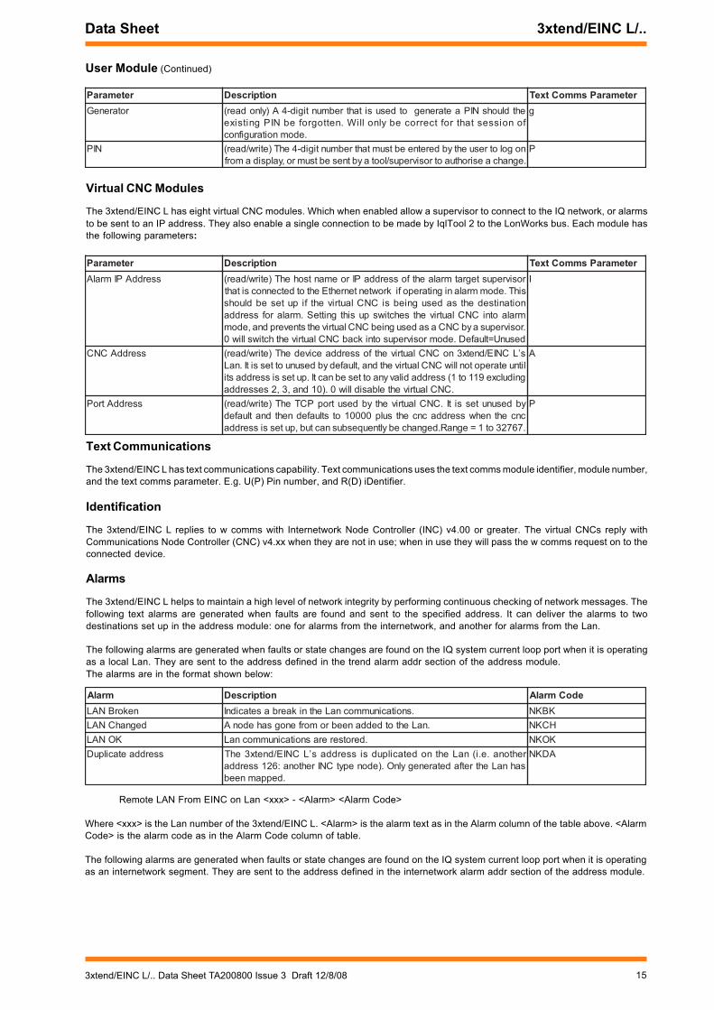
User Module (Continued)
Virtual CNC Modules
The 3xtend/EINC L has eight virtual CNC modules. Which when enabled allow a supervisor to connect to the IQ network, or alarmsto be sent to an IP address. They also enable a single connection to be made by IqlTool 2 to the LonWorks bus. Each module hasthe following parameters:
Text Communications
The 3xtend/EINC L has text communications capability. Text communications uses the text comms module identifier, module number,and the text comms parameter. E.g. U(P) Pin number, and R(D) iDentifier.
Identification
The 3xtend/EINC L replies to w comms with Internetwork Node Controller (INC) v4.00 or greater. The virtual CNCs reply withCommunications Node Controller (CNC) v4.xx when they are not in use; when in use they will pass the w comms request on to theconnected device.
Alarms
The 3xtend/EINC L helps to maintain a high level of network integrity by performing continuous checking of network messages. Thefollowing text alarms are generated when faults are found and sent to the specified address. It can deliver the alarms to twodestinations set up in the address module: one for alarms from the internetwork, and another for alarms from the Lan.
The following alarms are generated when faults or state changes are found on the IQ system current loop port when it is operatingas a local Lan. They are sent to the address defined in the trend alarm addr section of the address module.The alarms are in the format shown below:
Remote LAN From EINC on Lan <xxx> - <Alarm> <Alarm Code>
Where <xxx> is the Lan number of the 3xtend/EINC L. <Alarm> is the alarm text as in the Alarm column of the table above. <AlarmCode> is the alarm code as in the Alarm Code column of table.
The following alarms are generated when faults or state changes are found on the IQ system current loop port when it is operatingas an internetwork segment. They are sent to the address defined in the internetwork alarm addr section of the address module.
retemaraP noitpircseD retemaraPsmmoCtxeTrotareneG ehtdluohsNIPaetarenegotdesusitahtrebmuntigid-4A)ylnodaer(
fonoissestahtroftcerrocebylnolliW.nettogrofebNIPgnitsixe.edomnoitarugifnoc
g
NIP nogolotresuehtybderetneebtsumtahtrebmuntigid-4ehT)etirw/daer(.egnahcaesirohtuaotrosivrepus/lootaybtnesebtsumro,yalpsidamorfP
retemaraP noitpircseD retemaraPsmmoCtxeTsserddAPImralA rosivrepustegratmralaehtfosserddaPIroemantsohehT)etirw/daer(
sihT.edommralanignitarepofikrowtentenrehtEehtotdetcennocsitahtnoitanitsedehtsadesugniebsiCNClautrivehtfiputesebdluohs
mralaotniCNClautrivehtsehctiwspusihtgnitteS.mralarofsserdda.rosivrepusaybCNCasadesugniebCNClautrivehtstneverpdna,edom
desunU=tluafeD.edomrosivrepusotnikcabCNClautrivehthctiwslliw0
I
sserddACNC s’LCNIE/dnetx3noCNClautrivehtfosserddaecivedehT)etirw/daer(litnuetarepotonlliwCNClautrivehtdna,tluafedybdesunuottessitI.naL
gnidulcxe911ot1(sserddadilavynaottesebnactI.putessisserddasti.CNClautrivehtelbasidlliw0.)01dna,3,2sesserdda
A
sserddAtroP ybdesunutessitI.CNClautrivehtybdesutropPCTehT)etirw/daer(cncehtnehwsserddacncehtsulp00001otstluafednehtdnatluafed.76723ot1=egnaR.degnahcebyltneuqesbusnactub,putessisserdda
P
mralA noitpircseD edoCmralAnekorBNAL .snoitacinummocnaLehtnikaerbasetacidnI KBKN
degnahCNAL .naLehtotdeddaneebromorfenogsahedonA HCKNKONAL .derotsererasnoitacinummocnaL KOKN
sserddaetacilpuD rehtona.e.i(naLehtnodetacilpudsisserddas’LCNIE/dnetx3ehTsahnaLehtretfadetarenegylnO.)edonepytCNIrehtona:621sserdda
.deppamneeb
ADKN

16 3xtend/EINC L/.. Data Sheet TA200800 Issue 3 12/8/08
3xtend/EINC L/.. Data Sheet
Alarms (Continued)
The following alarms are generated when faults of state changes are found on the Ethernet port. They are sent to the addressdefined in the internetwork alarm addr section of the address module.
The following alarms are generated when faults or state changes are found on the LONWORKS network port. They are sent to theaddress defined in the internetwork alarm addr section of the address module.
The following alarm is generated when the 3xtend/EINC L’s Lan number is duplicated on the internetwork. It is sent to the addressdefined in the internetwork alarm addr section of the address module.
The alarms are in the format shown below:
Internetwork From EINC on Lan <xxx> - <Alarm> <Alarm Code>
Where <xxx> is the Lan number of the 3xtend/EINC L. <Alarm> is the alarm text as in the Alarm column of the table above. <AlarmCode> is the alarm code as in the Alarm Code column of table.
The following alarm is generated when the 3xtend/EINC L detects a node that thinks it is the only one on the network. It is sent toboth alarm addresses defined in the address module.
The alarm is in the format shown below:
Internetwork IP<xxx.xxx> - <Alarm>
Where <xxx.xxx> is the last two numbers of the IP address of the device that thinks it is the only device on the network. <Alarm>is the alarm text as in the Alarm column of the table above.
COMPATIBILITYSupervisors/Displays 963 v2.1, 915MDS >v3, 916, IQViewUtility software SET v6 (including IP Tool software)Controllers IQ3 controllers and IQ1, IQ2, and IQLEthernet Nodes Compatible with NXIP or EINC providing they are not used in an automatic IP addressing environment.LONWORKS network Not compatible with LONC. The LONC must be bound on a LONWORKS network, and 3xtend/EINC L
cannot be bound, an EINC and LINC must be used instead.
mralA noitpircseD edoCmralAnekorBkrowtenretnI .snoitacinummockrowtenretniehtnikaerbasetacidnI KBKN
degnahCkrowtenretnI .krowtenretniehtotdeddaneebromorfenogsahedonA HCKNKOkrowtenretnI .derotsererasnoitacinummockrowtenretnI KOKNpaM-eRdesuaC krowtenaretfakrowtenretnistignippamdetratssahLCNIE/dnetx3
.001>sisserddaesohwsecivedybdetarenegylnosisihT.egnahcHCKN
tliuBspaMllA ylnosisihT.dehsinifkrowtenretnipooltnerrucehtnognippamnaL.001>sisserddaesohwsecivedybdetareneg
HCKN
mralA noitpircseD edoCmralAnekorBkrwIPI .snoitacinummockrowtenretnitenrehtEehtnikaerbasetacidnI KBKN
degnahCkrwIPI .krowtenretnitenrehtEehtotdeddaneebromorfenogsahedonA HCKNKOkrwIPI .derotsererasnoitacinummockrowtenretnitenrehtE KOKN
paM-eRdesuaCPI naaretfakrowtenretnitenrehtEstignippamdetratssahLCNIE/dnetx3sisserddaesohwsecivedybdetarenegylnosisihT.egnahckrowtenPI
.001>
HCKN
tliuBspaMllAPI esohwsecivedybdetarenegylnosisihT.dehsinifgnippamkrowtenretnI.001>sisserdda
HCKN
mralA noitpircseD edoCmralAsserddaetacilpuD nodetacilpudsignitteshctiwssserddarebmunnaLs’LCNIE/dnetx3ehT
.deppamneebsahkrowtenretniehtretfadetarenegylnO.krowtenretniehtADKN
mralA noitpircseD edoCmralAfaedsiedonsihT sknihttahtedonrehtonasraehLCNIE/dnetx3ehtnehwdetarenegsisihT
erawdrahasierehtfiruccoylnolliwsihT.krowtenehtnoedonylnoehtsitibuss'ecivedehtro,eviecertontubtimsnartotedonaselbanetahttluaf
.tropPDUemasehtnorehtoottnereffidsiten
mralA noitpircseD edoCmralAnekorBkrwInoL LehtnikaerbasetacidnI NO W SKRO .snoitacinummockrowtenretnikrowten KBKN
degnahCkrwInoL .krowtenretniskrownoLehtotdeddaneebromorfenogsahedonA HCKNKOkrwInoL L NO W SKRO .derotsererasnoitacinummockrowtenretnikrowten KOKN
paM-eRdesuaCnoL degnahcnaLronekorbnaLaretfastignippamdetratssahLCNIE/dnetx3.001>sisserddaesohwsecivedybdetarenegylnosisihT.noitidnoc
HCKN
tliuBspaMllAnoL LehtnognippamkrowtenretnI NO W SKRO .dehsinifkrowtenretnikrowten.001>sisserddaesohwsecivedybdetarenegylnosisihT
HCKN

173xtend/EINC L/.. Data Sheet TA200800 Issue 3 Draft 12/8/08
Data Sheet 3xtend/EINC L/..
INSTALLATIONThe 3xtend/EINC L is mounted on a flat surface, e.g. a wall using 3 point mounting (3 screws and rawl plugs). The 3xtend/EINC L/24 is UL rated as ‘UL916, open energy management equipment’. The procedure involves:
CONNECTIONS
3xtend/EINC L/24LON
1 2
Power
Ethernet
100 m(max)
RJ45
Ethernet hub/switch
A standard Ethernet cable and anXCITE/XA adaptor may be used toconnect directly to the 3xtend/EINC L.
1 2 3 4 5 6 7 8 9 10
28 - 36 V24 V ~
24 Vac 24 Vac E28 Vdc +28V 0V E
28 to 36 Vdc24 Vac
L N
E
E
PSR/230/24-2.5
+28 V 0 V
L N
E24 Vac
E
ACC/24VAC
230 Vac 100 to 240 Vac
Using ACC/24VACtransformer
Using PSR/230/24-2.5 powersupply
~
LON
polarity independent
Normal current loop Lan cableis not recommended.Do not use screened cable.
X
TT
RR
1 2 3 4T- T+ R- R+
X
TT
RRTT
RR
1 2 3 4T- T+ R- R+
Current Loop Lan
2 part screw terminals, polarity independent
2 wire
4 wire
additional terminals
RS232 RJ11 (FCC68)
Currently this connection is unused.
If the IQ system current loop is not to beconnected (i.e. the unit is to only interfacebetween Ethernet and a LONWORKS network )a loop back connector must be fitted as shown.
1 2 3 4T- T+ R- R+
CAUTION: Do not apply mains power tothis connector.
Mounting the unitConnecting powerConnecting Ethernet if requiredConnecting IQ system current loop Lan if requiredReading End User Licence Agreement
Powering upConfiguring the unitChecking LEDsTesting the unit
A full description of installation is given in the 3xtend/EINC L/24 Installation Instructions TG200811, or the 3xtend/EINC L/230 InstallationInstructions TG200812. An appropriate mounting template is provided with the /24 version: 3xtend/EINC L/24 Template TG200813.
CAUTION: Do not apply power to this connector
Using 230V/24Vac transformer
24Vac
E
L N

18 3xtend/EINC L/.. Data Sheet TA200800 Issue 3 12/8/08
3xtend/EINC L/.. Data Sheet
CONNECTIONS (Continued)
3xtend/EINC L/230 (not available in USA)
LON
1 2
� 1 � # 2 % 3 $ �
Power230 Vac
X
TT
RR
1 2 3 4T- T+ R- R+
X
TT
RRTT
RR
1 2 3 4T- T+ R- R+
Current Loop Lan
2 part screw terminalspolarity independent2 wire
4 wire
additional terminals
~L N E
RS232 RJ11 (FCC68)
Caution: Do not apply power to this connector
Currently this connection is unused.
LON
polarity independent
Normal current loop Lan cableis not recommended.Do not use screened cable.
If the IQ system current loop is not to beconnected (i.e. the unit is to only interfacebetween Ethernet and LONWORKS network)a loop back connector must be fitted asshown.
1 2 3 4T- T+ R- R+
Ethernet
100 m(max)
RJ45
Ethernet hub/switch
A standard Ethernet cable and anXCITE/XA adaptor may be used toconnect directly to the 3xtend/EINC L.

193xtend/EINC L/.. Data Sheet TA200800 Issue 3 Draft 12/8/08
Data Sheet 3xtend/EINC L/..
DISPOSALCONTROL OF SUBSTANCES HAZARDOUS TO HEALTH UKGOVERNMENT REGULATIONS 2002 (COSHH) ASSESSMENTFOR DISPOSAL OF 3xtend/EINC L. No parts affected.
RECYCLING. All plastic and metal parts are recyclable. The printed circuitboard may be sent to any PCB recovery contractor to recoversome of the components for any metals such as gold and silver.
WEEE Directive :
At the end of their useful life the packagingand product should be disposed of using asuitable recycling centre.Do not dispose of with normal household waste.Do not burn.
ORDER CODESNon USA Order Code USA Order Code3XTEND/EINC L/230 not available in USA :3xtend/EINC L for 230 VAC power supply.3XTEND/EINC L/24 not available in USA :3xtend/EINC L for 24 Vac supply in NBOX plastic enclosure, including
busbar and screws.3XTEND/EINC L/USA/UL/24 882001600 :3xtend/EINC L for 24 Vac supply in NBOX plastic enclosure, including
busbar and screws.
Accessories
XCITE/XA/5 882001100 :Pack of 5 Ethernet connector adapters for direct connection of PCto 3xtend/EINC L using standard Ethernet cable.
LONTERMINATOR 882000350 Universal LONWORKS network terminator FTT, LPT-10, or TPT/XF1250(see LONTERMINATOR data sheet TA200229).
IQLROUTER/24VAC not available in USA IQL Router with 24Vac power option.IQLROUTER/230 not available in USA IQL Router with 230 Vac power option.IQLROUTER/USA/UL/24V 88200130 IQL Router with 24Vac power option.
SPECIFICATIONElectrical
CPU :Intel PXA255CPU speed :200 MHzMemory :8 Mbyte Flash, 32 Mbyte SDRAMInput power
/230 :230 Vac -10%, +15%, 50/60 Hz, 24 VA(not available in USA).
/24 :28 to 36 Vdc , or 24 Vac ±10%, 50/60Hz.Fusing
/230 :The pcb is protected by a 6.3 A fast blowfuse. A 125 mA fuse protects thetransformer. (not available in USA)
/24 :Pcb protected by a 6.3 A fast blow fuse.Protected against reverse polarity.
Consumption :8 VA maximumPower failure protection:Configuration data is stored in
non-volatile memory (Flash).Current loop
Transmission :20 mA, two wire current loop,optoisolated, polarity independentreceiver, balanced transmitter.
Distance :Between units dependent on baud rateand cable type (see below)
Baud rate :Set by switch to 9k6, 19k2, 38k4 baud.Set to match other nodes onLan/internetwork. 38k4 only available oninternetwork.
EthernetTransmission :10/100 BASE-T autonegotiatedDistance :100 m (109 yds) to hub
LONWORKS network :FTT (Free Topology), 78 k baud,transformer isolated. Single termination(RC network). Can also use LPT10 (LoopPowered free Topology).
LON FTT distance :Maximum bus length and node to nodedistance depend on cable type.
Note that this does not include cable recommended for thecurrent loop Lan.LON transceiver :FTT-10Lan number :Selectable by board switches - Lan
number set to be unique on internetwork;116 nodes addressable (1 to 119,excluded addresses 2,3, and 10).
Storage Media :SD card socket takes SD/MMC card(Secure digital/Multimedia card) forfirmware upgrades.
Device address :The address of the 3xtend/EINC L onthe Lan is 126. The 8 virtual CNCaddresses are set in configuration mode,to be unique on Lan; 116 nodesaddressable (1 to 119, excludedaddresses 2,3, and 10).
elbaC duab6k9 2k91duab
4k83duab
fo.oNseriW
2819nedleB m0001)sdy0901(
m007)sdy567(
m005)sdy545( 2
7029nedleB m0001)sdy0901(
m005)sdy545(
m053sdy083( 2
dnerT002/FH/22/1/1/PT
)1678nedleB(
m007)sdy567(
m053)sdy083(
m052)sdy072( 2
dnerT002/FH/22/2/2/PT
)3278nedleB(
m005)sdy545(
m052)sdy072(
m521)sdy531( 4
selbaCdednemmoceR htgnelsubxaM otedonxaMedon
20158nedleB )sdy545(m005 )sdy545(m005dnerT
002/FH/61/0/1/PT)1748nedleB(
)sdy545(m005 )sdy034(m004
GWA22,VIleveLLU )sdy545(m005 )sdy034(m0048.0x2x2Y)tS(YJ )sdy545(m005 )sdy053(m023
GWA42,5.taCA865AIT )sdy094(m054 )sdy072(m052

3xtend/EINC L/.. Data Sheet
20 3xtend/EINC L/.. Data Sheet TA200800 Issue 3 12/8/08
Trend Control Systems LimitedP.O. Box 34, Horsham, West Sussex, RH12 2YF, UK. Tel:+44 (0)1403 211888 Fax:+44 (0)1403 241608 www. trend-controls.comTrend Control Systems USA6670 185th Avenue NE, Redmond, Washington 98052, USA. Tel: (425)897-3900, Fax: (425)869-8445 www. trend-controls.com
Please send any comments about this or any other Trend technical publication to [email protected]
Manufactured for and on behalf of the Environmental and Combustion Controls Division of Honeywell Technologies Sàrl, Ecublens, Route du Bois37,Switzerland by its Authorized Representative, Trend Control Systems Limited.
©Trend Control Systems Limited 2007. Trend Control Systems Limited reserves the right to revise this publication from time to time and makechanges to the content hereof without obligation to notify any person of such revisions or changes.
SPECIFICATION (Continued)
IndicatorsPower/Alarm :(Blue) ON to indicate that the power
supply is connected. Flashes if there isa fault condition. OFF indicates a supplyfailure or processor problem. A slowdouble pulse indicates that an IP addresshas not been established. This occursbriefly on startup when using a DHCPserver of for a more prolonged period ifin automatic addressing mode without aDHCP server.
Current LoopTX :(yellow) ON if current is flowing from the
current loop network transmitter.RX :(yellow) ON if current is entering the
current loop network receiver.OK :(green) ON if 3xtend/EINC L
successfully communicating over currentloop (LED will flash intermittently as ittries to communicate).
EthernetOK :(green) ON if the 3xtend/EINC L has
successfully communicated with at leastone other IQ system device on theEthernet. ON if internetwork on Ethernethas been constructed. OFF if EINC alone(e.g. using virtual CNCs only).
Link :(green) ON if the 3xtend/EINC L has agood Ethernet connection. If OFF itindicates a faulty Ethernet connection.
Data :(yellow) Flashes when a package of datais being received from the Ethernetnetwork.
LONWORKS networkLON OK :(green) ON if 3xtend/EINC L successfully
communicating over LonWorks bus withat least one other device.
LON Service :(yellow) Flashes when service buttonis pressed.
Environmental
EMCEmissions :EN50081-1:1992Immunity :EN61000-3-2:1995 + A1:1998 +
A2:1998EN61000-3-3:1995EN61000-6-2:1999
SafetyEU
/230 :EN61010:2001 (not available in USA)/24 :EN61010:2001
USA/Canada/24 :UL rated as ‘UL916 listed open energy
management equipment’.Canada
/24 :CSA22.2 No. 205-M1983 - SignalEquipment.
Ambient limitsstorage
temp :-10 °C (14 °F) to +50 °C (122 °F)humidity :0 to 90 %RH non-condensing
operatingtemp :0 °C (32 °F) to 45 °C (113 °F)humidity :0 to 80 %RH non-condensing
Protection/230 :IP40 (not available in USA)/24 :IP42, NEMA3R
Version This document covers:Firmware :v1.2Boards
Baseboard :AP105227 issue 4Processor :AP104981 issue 3
© Echelon Corporation. Echelon, LON, Neuron, LONWORKS areU.S. registered trademarks of Echelon Corporation. LONMARKis a trademark of Echelon Corporation.
Mechanical
Dimensions/230 :302 mm (11.89”) x 266 mm (10.47”) x
60 mm (2.36”). (not available in USA)/24 :227 mm (8.94”) x 218 mm (8.58”) x
60 mm (2.36”).Weight
/230 :3.05 Kg, 6.72 lbs (not available in USA)/24 :0.994 Kg, 2.18 lbs
Enclosure material/230 :Polyester powder coated steel. (not
available in USA)Connectors
Current loop Lan :2 part connectors with screw terminalsfor 0.5 to 2.5 mm2 cross section area (14to 20 AWG) cable.
RS232 :RJ11 (FCC68). Connect using RJ11 toRJ11 (crossover cable)CABLE/EJ105650, RJ11 to 25 way Dmale CABLE/EJ105651, orCABLE/EJ105651 with 25 way D femaleto 5 in line male CABLE/78-1172
Ethernet :RJ45 connector, unshielded or shieldedtwisted pair (UTP or FTP) cable 10 Mbps,100 m (109 yds), 10 BASE-T. Cable andconnectors are available (see productcodes). Connect local supervisor(Ethernet) using adjacent hub or directlyusing standard Ethernet cable andXCITE/XA adapter.
Supply :2 part connectors with screw terminalsfor 0.5 to 2.5 mm2 cross section area (14to 20 AWG) cable.
LON :2 part connectors with screw terminalsfor 0.5 to 2.5 mm2 cross section area (14to 20 AWG) cable.
SD :SD card slot for SD or MMC cards.