Mobile Enforcement System User Manual 0 DS-MI9605-GA Series Mobile Enforcement System User Manual

Welcome message from author
This document is posted to help you gain knowledge. Please leave a comment to let me know what you think about it! Share it to your friends and learn new things together.
Transcript

Mobile Enforcement System User Manual
0
DS-MI9605-GA Series Mobile Enforcement System
User Manual
Mobile Enforcement System User Manual
Quick Start Guide
COPYRIGHT © 2017 Hangzhou Hikvision Digital Technology Co., Ltd.
ALL RIGHTS RESERVED.
Any and all information, including, among others, wordings, pictures, graphs are the properties of
Hangzhou Hikvision Digital Technology Co., Ltd. or its subsidiaries (hereinafter referred to be
“Hikvision”). This user manual (hereinafter referred to be “the Manual”) cannot be reproduced,
changed, translated, or distributed, partially or wholly, by any means, without the prior written
permission of Hikvision. Unless otherwise stipulated, Hikvision does not make any warranties,
guarantees or representations, express or implied, regarding to the Manual.
About this Manual
This Manual is applicable to Mobile Enforcement System.
The Manual includes instructions for using and managing the product. Pictures, charts, images and
all other information hereinafter are for description and explanation only. The information
contained in the Manual is subject to change, without notice, due to firmware updates or other
reasons. Please find the latest version in the company website
(http://overseas.hikvision.com/en/).
Please use this user manual under the guidance of professionals.
Trademarks Acknowledgement
and other Hikvision’s trademarks and logos are the properties of Hikvision in various
jurisdictions. Other trademarks and logos mentioned below are the properties of their respective
owners.
Legal Disclaimer
TO THE MAXIMUM EXTENT PERMITTED BY APPLICABLE LAW, THE PRODUCT DESCRIBED, WITH ITS
HARDWARE, SOFTWARE AND FIRMWARE, IS PROVIDED “AS IS”, WITH ALL FAULTS AND ERRORS,
AND HIKVISION MAKES NO WARRANTIES, EXPRESS OR IMPLIED, INCLUDING WITHOUT LIMITATION,
MERCHANTABILITY, SATISFACTORY QUALITY, FITNESS FOR A PARTICULAR PURPOSE, AND
NON-INFRINGEMENT OF THIRD PARTY. IN NO EVENT WILL HIKVISION, ITS DIRECTORS, OFFICERS,
EMPLOYEES, OR AGENTS BE LIABLE TO YOU FOR ANY SPECIAL, CONSEQUENTIAL, INCIDENTAL, OR
INDIRECT DAMAGES, INCLUDING, AMONG OTHERS, DAMAGES FOR LOSS OF BUSINESS PROFITS,
BUSINESS INTERRUPTION, OR LOSS OF DATA OR DOCUMENTATION, IN CONNECTION WITH THE
USE OF THIS PRODUCT, EVEN IF HIKVISION HAS BEEN ADVISED OF THE POSSIBILITY OF SUCH
DAMAGES.
REGARDING TO THE PRODUCT WITH INTERNET ACCESS, THE USE OF PRODUCT SHALL BE WHOLLY
AT YOUR OWN RISKS. HIKVISION SHALL NOT TAKE ANY RESPONSIBILITES FOR ABNORMAL
OPERATION, PRIVACY LEAKAGE OR OTHER DAMAGES RESULTING FROM CYBER ATTACK, HACKER
ATTACK, VIRUS INSPECTION, OR OTHER INTERNET SECURITY RISKS; HOWEVER, HIKVISION WILL
PROVIDE TIMELY TECHNICAL SUPPORT IF REQUIRED.
SURVEILLANCE LAWS VARY BY JURISDICTION. PLEASE CHECK ALL RELEVANT LAWS IN YOUR
JURISDICTION BEFORE USING THIS PRODUCT IN ORDER TO ENSURE THAT YOUR USE CONFORMS
THE APPLICABLE LAW. HIKVISION SHALL NOT BE LIABLE IN THE EVENT THAT THIS PRODUCT IS
USED WITH ILLEGITIMATE PURPOSES.
IN THE EVENT OF ANY CONFLICTS BETWEEN THIS MANUAL AND THE APPLICABLE LAW, THE LATER
PREVAILS.
Mobile Enforcement System User Manual
1
Regulatory Information
FCC Information
Please take attention that changes or modification not expressly approved by the party
responsible for compliance could void the user’s authority to operate the equipment.
Note: This product has been tested and found to comply with the limits for a Class B digital device,
pursuant to Part 15 of the FCC Rules. These limits are designed to provide reasonable protection
against harmful interference in a residential installation. This product generates, uses, and can
radiate radio frequency energy and, if not installed and used in accordance with the instructions,
may cause harmful interference to radio communications. However, there is no guarantee that
interference will not occur in a particular installation. If this product does cause harmful
interference to radio or television reception, which can be determined by turning the equipment
off and on, the user is encouraged to try to correct the interference by one or more of the
following measures:
—Reorient or relocate the receiving antenna.
—Increase the separation between the equipment and receiver.
—Connect the equipment into an outlet on a circuit different from that to which the receiver is
connected.
—Consult the dealer or an experienced radio/TV technician for help.
FCC Conditions
This device complies with part 15 of the FCC Rules. Operation is subject to the following two
conditions:
1. This device may not cause harmful interference.
2. This device must accept any interference received, including interference that may cause
undesired operation.
EU Conformity Statement
This product and - if applicable - the supplied accessories too are marked with "CE" and
comply therefore with the applicable harmonized European standards listed under the
EMC Directive 2004/108/EC, the RoHS Directive 2011/65/EU, the R&TTE Directive 1999/5/EC.
2012/19/EU (WEEE directive): Products marked with this symbol cannot be disposed of
as unsorted municipal waste in the European Union. For proper recycling, return this
product to your local supplier upon the purchase of equivalent new equipment, or
dispose of it at designated collection points. For more information see: www.recyclethis.info
2006/66/EC (battery directive): This product contains a battery that cannot be disposed
of as unsorted municipal waste in the European Union. See the product documentation
for specific battery information. The battery is marked with this symbol, which may
include lettering to indicate cadmium (Cd), lead (Pb), or mercury (Hg). For proper recycling, return
Mobile Enforcement System User Manual
2
the battery to your supplier or to a designated collection point. For more information see:
www.recyclethis.info
Industry Canada ICES-003 Compliance
This device meets the CAN ICES-3 (B)/NMB-3(B) standards requirements.
This device complies with Industry Canada licence-exempt RSS standard(s). Operation is subject to
the following two conditions:
(1) this device may not cause interference, and
(2) this device must accept any interference, including interference that may cause undesired
operation of the device.
Le présent appareil est conforme aux CNR d'Industrie Canada applicables aux appareils
radioexempts de licence. L'exploitation est autorisée aux deux conditions suivantes :
(1) l'appareil ne doit pas produire de brouillage, et
(2) l'utilisateur de l'appareil doit accepter tout brouillage radioélectrique subi, même si le
brouillage est susceptible d'en compromettre le fonctionnement.
Under Industry Canada regulations, this radio transmitter may only operate using an antenna of a
type and maximum (or lesser) gain approved for the transmitter by Industry Canada. To reduce
potential radio interference to other users, the antenna type and its gain should be so chosen that
the equivalent isotropically radiated power (e.i.r.p.) is not more than that necessary for successful
communication.
Conformément à la réglementation d'Industrie Canada, le présent émetteur radio peut
fonctionner avec une antenne d'un type et d'un gain maximal (ou inférieur) approuvé pour
l'émetteur par Industrie Canada. Dans le but de réduire les risques de brouillage radioélectrique à
l'intention des autres utilisateurs, il faut choisir le type d'antenne et son gain de sorte que la
puissance isotrope rayonnée équivalente (p.i.r.e.) ne dépasse pas l'intensité nécessaire à
l'établissement d'une communication satisfaisante.
Mobile Enforcement System User Manual
3
Applicable Models
This manual is applicable to DS-MI9605-GA.
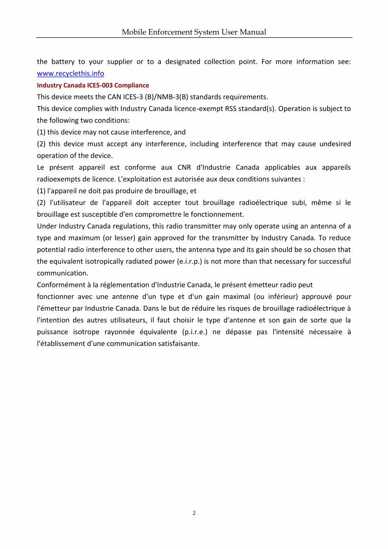
Symbol Conventions
The symbols that may be found in this document are defined as follows.
Symbol Description
Provides additional information to emphasize or supplement important points of the main text.
Indicates a potentially hazardous situation, which if not avoided, could result in equipment damage, data loss, performance degradation, or unexpected results.
Indicates a hazard with a high level of risk, which if not avoided, will result in death or serious injury.
Mobile Enforcement System User Manual
4
Safety Instructions
Proper configuration of all passwords and other security settings is the responsibility of the installer and/or end-user.
In the use of the product, you must be in strict compliance with the electrical safety regulations of the nation and region. Please refer to technical specifications for detailed information.
Input voltage should meet both the SELV (Safety Extra Low Voltage) and the Limited Power Source with 100~240 VAC or 12 VDC according to the IEC60950-1 standard. Please refer to technical specifications for detailed information.
Do not connect several devices to one power adapter as adapter overload may cause over-heating or a fire hazard.
Please make sure that the plug is firmly connected to the power socket.
If smoke, odor or noise rise from the device, turn off the power at once and unplug the power cable, and then please contact the service center.
Preventive and Cautionary Tips
Before connecting and operating your device, please be advised of the following tips:
Ensure unit is installed in a well-ventilated, dust-free environment.
Unit is designed for indoor use only.
Keep all liquids away from the device.
Ensure environmental conditions meet factory specifications.
Ensure unit is properly secured to a rack or shelf. Major shocks or jolts to the unit as a result of dropping it may cause damage to the sensitive electronics within the unit.
Use the device in conjunction with an UPS if possible.
Power down the unit before connecting and disconnecting accessories and peripherals.
A factory recommended HDD should be used for this device.
Improper use or replacement of the battery may result in hazard of explosion. Replace with the same or equivalent type only. Dispose of used batteries according to the instructions provided by the battery manufacturer.
Mobile Enforcement System User Manual
5
TABLE OF CONTENTS Chapter 1 Introduction ................................................................................................................... 8
1.1 Overview ............................................................................................................................. 8
1.2 Main Features ...................................................................................................................... 8
Chapter 2 Assembly Parts Introduction .......................................................................................... 9
2.1 Package List ......................................................................................................................... 9
2.2 Panel Description ............................................................................................................... 10
2.2.1 Front Panel ............................................................................................................... 10
2.2.2 Rear Panel ................................................................................................................. 11
2.2.3 Device Load Information ........................................................................................... 12
2.3 Manual Controller Introduction ......................................................................................... 13
Chapter 3 Installation ................................................................................................................... 16
3.1 Install HDD ......................................................................................................................... 16
3.2 Install SIM Card .................................................................................................................. 18
Chapter 4 Menu Operation ........................................................................................................... 21
4.1 Enter Main Menu............................................................................................................... 21
4.2 Enter Sub-Menu ................................................................................................................ 21
4.3 Edit Parameters ................................................................................................................. 22
4.4 Exit Menu .......................................................................................................................... 22
4.5 Positioning Cursor on an Item ............................................................................................ 22
4.6 Check a Checkbox .............................................................................................................. 23
4.7 Edit Dropdown List ............................................................................................................ 23
4.8 Edit a Text field .................................................................................................................. 23
4.9 Save/Cancel Settings .......................................................................................................... 23
Chapter 5 Start Up Device............................................................................................................. 24
5.1 Startup .............................................................................................................................. 24
5.2 Set Admin Password .......................................................................................................... 24
Chapter 6 Network ....................................................................................................................... 25
6.1 Local Network Settings ...................................................................................................... 25
6.2 Dialing Settings .................................................................................................................. 25
6.3 Firewall Settings ................................................................................................................ 26
Chapter 7 IP Camera ..................................................................................................................... 28
7.1 Activate IP Camera ............................................................................................................. 28
7.2 Automatically Add IP Camera ............................................................................................. 28
7.3 Manually Add IP Cameras .................................................................................................. 29
7.3.1 Quick Add ................................................................................................................. 29
7.3.2 Manual Add .............................................................................................................. 30
7.4 Edit IP Camera ................................................................................................................... 30
7.4.1 Edit Added IP Camera................................................................................................ 30
7.4.2 Edit Un-Added IP Camera .......................................................................................... 31
7.5 Delete IP Cameras.............................................................................................................. 31
Chapter 8 Camera Management ................................................................................................... 32
Mobile Enforcement System User Manual
6
8.1 OSD Settings ...................................................................................................................... 32
8.2 Road Name Overlay ........................................................................................................... 32
Chapter 9 Live View ...................................................................................................................... 34
9.1 PTZ Control Settings........................................................................................................... 34
9.2 PTZ Operations .................................................................................................................. 34
9.2.1 PTZ Parameters ......................................................................................................... 34
9.2.2 Preset Settings .......................................................................................................... 37
Chapter 10 HDD Management ...................................................................................................... 39
10.1.1 Format HDD ............................................................................................................ 39
10.1.2 Set Overwrite Mode ................................................................................................ 39
10.1.3 View S.M.A.R.T Information .................................................................................... 40
Chapter 11 Recording and Capture ............................................................................................... 41
11.1 Record Parameters .......................................................................................................... 41
11.2 All-Day Recording ............................................................................................................ 41
11.3 Manual Recording ............................................................................................................ 42
11.4 Manual Capture ............................................................................................................... 42
Chapter 12 Traffic Violation Operations ....................................................................................... 43
12.1 Traffic Violation Recording ............................................................................................... 43
12.1.1 Set Traffic Violation ................................................................................................. 43
12.1.2 Start Traffic Violation Recording .............................................................................. 43
12.2 Traffic Violation Capture .................................................................................................. 44
12.2.1 Set Traffic Violation Capture Parameters ................................................................. 44
12.2.2 Capture Traffic Violation Pictures ............................................................................ 45
12.3 Picture Comparison ......................................................................................................... 45
12.3.1 Picture Composition Parameters ............................................................................. 45
12.3.2 Start Picture Composition ....................................................................................... 46
Chapter 13 Playback ..................................................................................................................... 47
Chapter 14 Platform ..................................................................................................................... 49
Chapter 15 Backup........................................................................................................................ 50
Chapter 16 Events and Alarms ...................................................................................................... 51
16.1 Exception Settings ........................................................................................................... 51
16.2 Alarm Input Settings ........................................................................................................ 51
16.3 Alarm Output Settings ..................................................................................................... 52
16.4 Speeding Alarm ............................................................................................................... 53
Chapter 17 User Account Management ........................................................................................ 55
Chapter 18 General System Configuration .................................................................................... 56
18.1 Touchscreen Settings ....................................................................................................... 56
18.2 GPS Settings .................................................................................................................... 56
18.3 Configure Basic Display Settings ....................................................................................... 57
18.4 Configure DST Settings ..................................................................................................... 57
18.5 Configure Advanced Display Settings ............................................................................... 58
Chapter 19 Maintenance .............................................................................................................. 60
19.1 View Status ..................................................................................................................... 60
Mobile Enforcement System User Manual
7
19.2 System Information ......................................................................................................... 60
19.3 Log Management ............................................................................................................. 60
19.3.1 Search Log .............................................................................................................. 61
19.3.2 Export Log ............................................................................................................... 61
19.4 Upgrade System ............................................................................................................... 62
19.4.1 Upgrade by USB device ........................................................................................... 62
19.4.2 Upgrade by FTP ....................................................................................................... 63
19.5 Restore Default Settings ................................................................................................... 64
19.6 Import/Export Configuration Files ................................................................................... 64
19.7 RS-232 Serial Port Settings ............................................................................................... 65
Chapter 20 Shutdown ................................................................................................................... 67
20.1 Boot Settings ................................................................................................................... 67
20.1.1 Shutdown Delay ...................................................................................................... 67
20.1.2 Timing On/Off ......................................................................................................... 67
20.2 Manual Shutdown ........................................................................................................... 68
Chapter 21 Appendix .................................................................................................................... 69
21.1 HDD Storage Chart ........................................................................................................... 69
21.2 Troubleshooting ............................................................................................................... 70
21.3 Recommended Sub-stream for 3G Network Transmission ................................................ 73
Mobile Enforcement System User Manual
8
Chapter 1 Introduction
1.1 Overview
DS-MI9605-GA series mobile enforcement system, hereinafter referred to as system or device, as a self-developed product adopts multiple key technology, including local video storage, 3G/4G dialing, wireless network transmission, satellite positioning, remote control, and light supplement, make it perfectly meet the demand of all-day enforcement.
Owing to these functions, the DS-MI9605-GA series mobile enforcement system is widely applied to the police vans, special vehicles, emergency scenes, etc., providing a complete solution for the traffic law enforcement, security protection, emergency commanding and other surveillance projects.
1.2 Main Features
1-ch 1080p positioning system lite and 4-ch network camera.
H.265 video compression for main stream and sub-stream.
1-ch VGA video output with resolution of 1280 × 800.
Pluggable dummy HDD supporting two 2.5-inch HDDs/SSDs.
Dummy HDD adopts HDD/SSD vibration damping technology.
IR and white light illumination help to capture high quality images in dim light environment.
Load name overlay feature records the geographical information of video evidence.
Operate menu and control positioning system lite via single and multi-touch features.
Wireless cluster intercom function.
Power-off protection prevents key data from loss.
Dummy HDD provides smart temperature-control module and USB data export interface.
Built-in GPS (Global Positioning System) module precisely positioning the vehicle via the satellite and recording the location information in the video stream.
Device adopts the aviation plug design to ensure signal stability.
Wide-range power input.
Aluminum die-cast chassis with no-fan design well adaptable to working environment.
Mobile Enforcement System User Manual
9
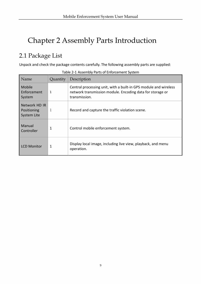
Chapter 2 Assembly Parts Introduction
2.1 Package List
Unpack and check the package contents carefully. The following assembly parts are supplied:
Table 2-1 Assembly Parts of Enforcement System
Name Quantity Description
Mobile Enforcement System
1
Central processing unit, with a built-in GPS module and wireless network transmission module. Encoding data for storage or transmission.
Network HD IR Positioning System Lite
1 Record and capture the traffic violation scene.
Manual Controller
1 Control mobile enforcement system.
LCD Monitor 1 Display local image, including live view, playback, and menu operation.
Mobile Enforcement System User Manual
10
2.2 Panel Description
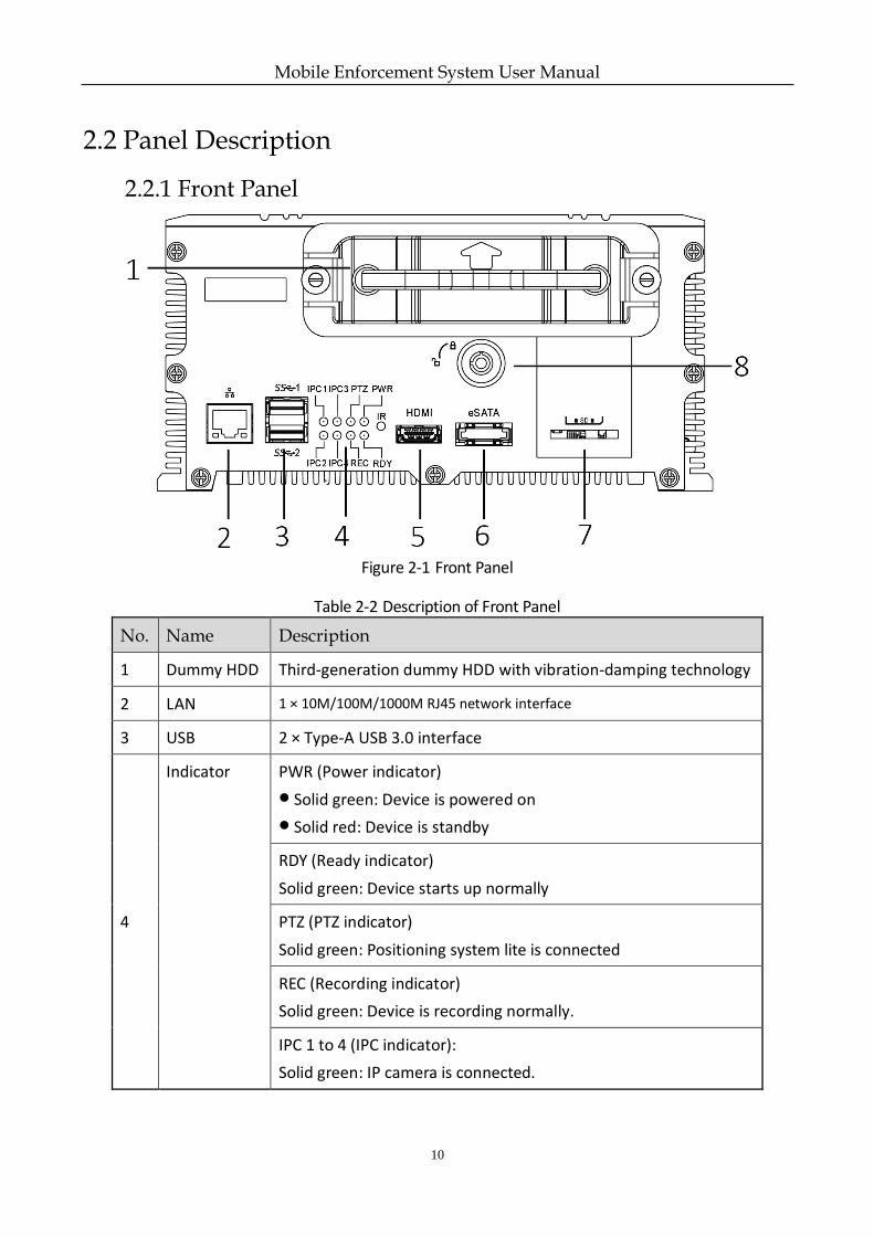
2.2.1 Front Panel
Figure 2-1 Front Panel
Table 2-2 Description of Front Panel
No. Name Description
1 Dummy HDD Third-generation dummy HDD with vibration-damping technology
2 LAN 1 × 10M/100M/1000M RJ45 network interface
3 USB 2 × Type-A USB 3.0 interface
4
Indicator PWR (Power indicator)
Solid green: Device is powered on
Solid red: Device is standby
RDY (Ready indicator)
Solid green: Device starts up normally
PTZ (PTZ indicator)
Solid green: Positioning system lite is connected
REC (Recording indicator)
Solid green: Device is recording normally.
IPC 1 to 4 (IPC indicator):
Solid green: IP camera is connected.
Mobile Enforcement System User Manual
11
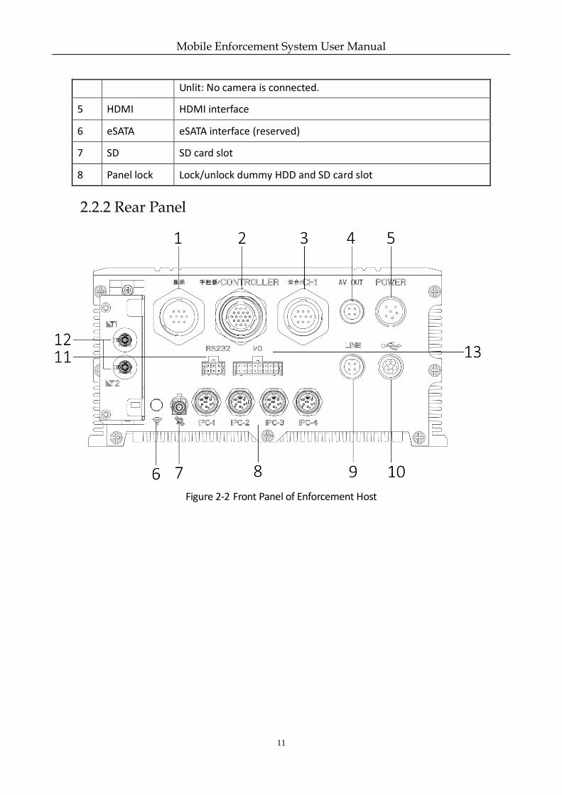
2.2.2 Rear Panel
Figure 2-2 Front Panel of Enforcement Host
Unlit: No camera is connected.
5 HDMI HDMI interface
6 eSATA eSATA interface (reserved)
7 SD SD card slot
8 Panel lock Lock/unlock dummy HDD and SD card slot
Mobile Enforcement System User Manual
12
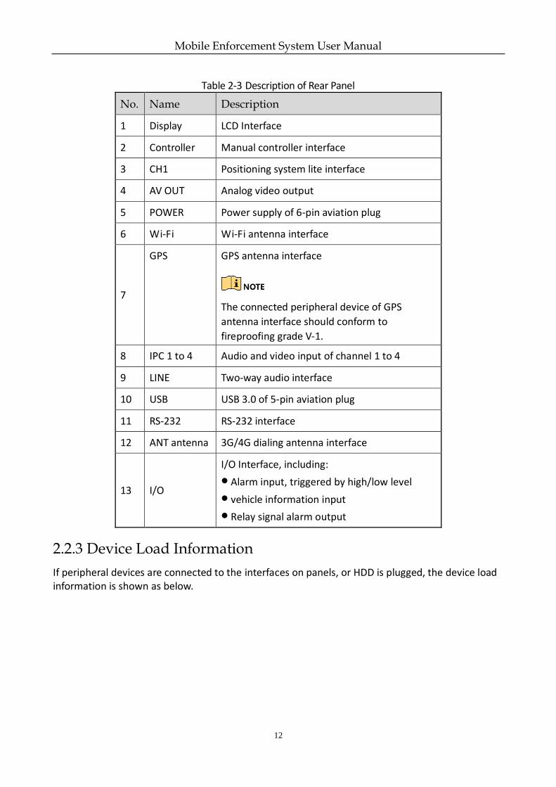
Table 2-3 Description of Rear Panel
No. Name Description
1 Display LCD Interface
2 Controller Manual controller interface
3 CH1 Positioning system lite interface
4 AV OUT Analog video output
5 POWER Power supply of 6-pin aviation plug
6 Wi-Fi Wi-Fi antenna interface
7
GPS GPS antenna interface
The connected peripheral device of GPS
antenna interface should conform to
fireproofing grade V-1.
8 IPC 1 to 4 Audio and video input of channel 1 to 4
9 LINE Two-way audio interface
10 USB USB 3.0 of 5-pin aviation plug
11 RS-232 RS-232 interface
12 ANT antenna 3G/4G dialing antenna interface
13 I/O
I/O Interface, including:
Alarm input, triggered by high/low level
vehicle information input
Relay signal alarm output
2.2.3 Device Load Information
If peripheral devices are connected to the interfaces on panels, or HDD is plugged, the device load information is shown as below.
Mobile Enforcement System User Manual
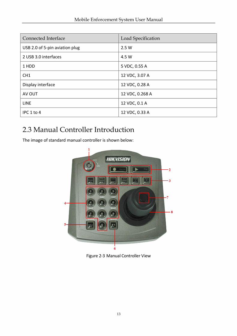
13
Connected Interface Load Specification
USB 2.0 of 5-pin aviation plug 2.5 W
2 USB 3.0 interfaces 4.5 W
1 HDD 5 VDC, 0.55 A
CH1 12 VDC, 3.07 A
Display interface 12 VDC, 0.28 A
AV OUT 12 VDC, 0.268 A
LINE 12 VDC, 0.1 A
IPC 1 to 4 12 VDC, 0.33 A
2.3 Manual Controller Introduction
The image of standard manual controller is shown below:
Figure 2-3 Manual Controller View
Mobile Enforcement System User Manual
14
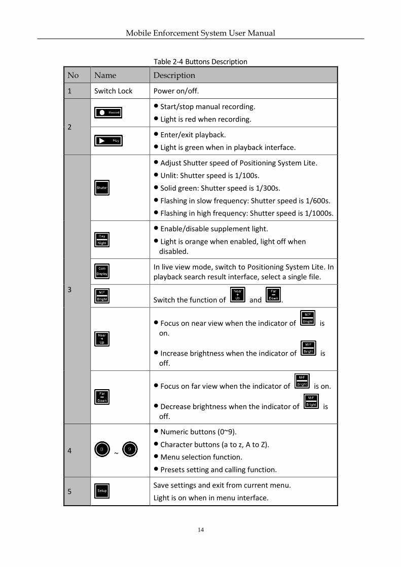
Table 2-4 Buttons Description
No Name Description
1 Switch Lock Power on/off.
2
Start/stop manual recording.
Light is red when recording.
Enter/exit playback.
Light is green when in playback interface.
3
Adjust Shutter speed of Positioning System Lite.
Unlit: Shutter speed is 1/100s.
Solid green: Shutter speed is 1/300s.
Flashing in slow frequency: Shutter speed is 1/600s.
Flashing in high frequency: Shutter speed is 1/1000s.
Enable/disable supplement light.
Light is orange when enabled, light off when disabled.
In live view mode, switch to Positioning System Lite. In playback search result interface, select a single file.
Switch the function of and .
Focus on near view when the indicator of is on.
Increase brightness when the indicator of is off.
Focus on far view when the indicator of is on.
Decrease brightness when the indicator of is off.
4 ~
Numeric buttons (0~9).
Character buttons (a to z, A to Z).
Menu selection function.
Presets setting and calling function.
5
Save settings and exit from current menu.
Light is on when in menu interface.
Mobile Enforcement System User Manual
15
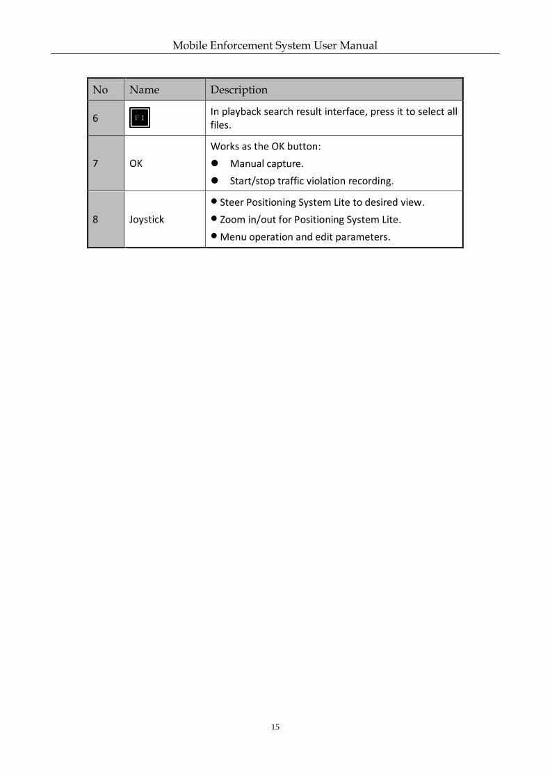
No Name Description
6
In playback search result interface, press it to select all files.
7 OK
Works as the OK button:
Manual capture.
Start/stop traffic violation recording.
8 Joystick
Steer Positioning System Lite to desired view.
Zoom in/out for Positioning System Lite.
Menu operation and edit parameters.
Mobile Enforcement System User Manual
16
Chapter 3 Installation
3.1 Install HDD
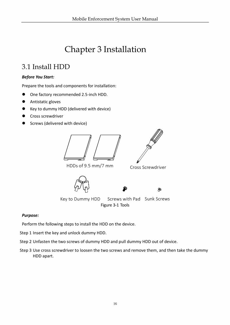
Before You Start:
Prepare the tools and components for installation:
One factory recommended 2.5-inch HDD.
Antistatic gloves
Key to dummy HDD (delivered with device)
Cross screwdriver
Screws (delivered with device)
Figure 3-1 Tools
Purpose:
Perform the following steps to install the HDD on the device.
Step 1 Insert the key and unlock dummy HDD.
Step 2 Unfasten the two screws of dummy HDD and pull dummy HDD out of device.
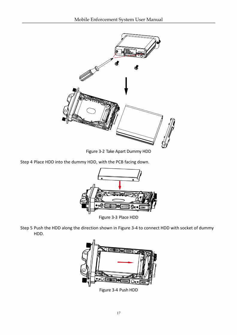
Step 3 Use cross screwdriver to loosen the two screws and remove them, and then take the dummy HDD apart.
Mobile Enforcement System User Manual
17
Figure 3-2 Take Apart Dummy HDD
Step 4 Place HDD into the dummy HDD, with the PCB facing down.
Figure 3-3 Place HDD
Step 5 Push the HDD along the direction shown in Figure 3-4 to connect HDD with socket of dummy HDD.
Figure 3-4 Push HDD
Mobile Enforcement System User Manual
18
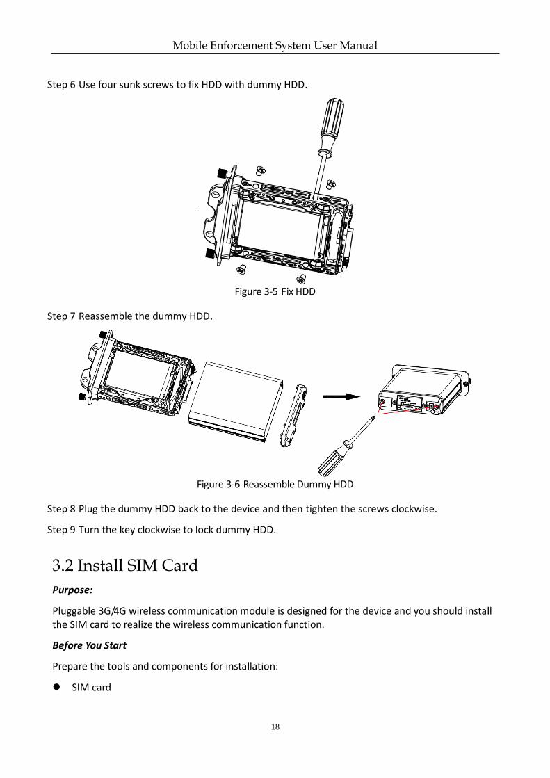
Step 6 Use four sunk screws to fix HDD with dummy HDD.
Figure 3-5 Fix HDD
Step 7 Reassemble the dummy HDD.
Figure 3-6 Reassemble Dummy HDD
Step 8 Plug the dummy HDD back to the device and then tighten the screws clockwise.
Step 9 Turn the key clockwise to lock dummy HDD.
3.2 Install SIM Card
Purpose:
Pluggable 3G/4G wireless communication module is designed for the device and you should install the SIM card to realize the wireless communication function.
Before You Start
Prepare the tools and components for installation:
SIM card
Mobile Enforcement System User Manual
19
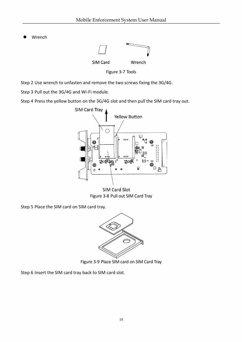
Wrench
Figure 3-7 Tools
Step 2 Use wrench to unfasten and remove the two screws fixing the 3G/4G.
Step 3 Pull out the 3G/4G and Wi-Fi module.
Step 4 Press the yellow button on the 3G/4G slot and then pull the SIM card tray out.
Figure 3-8 Pull out SIM Card Tray
Step 5 Place the SIM card on SIM card tray.
Figure 3-9 Place SIM card on SIM Card Tray
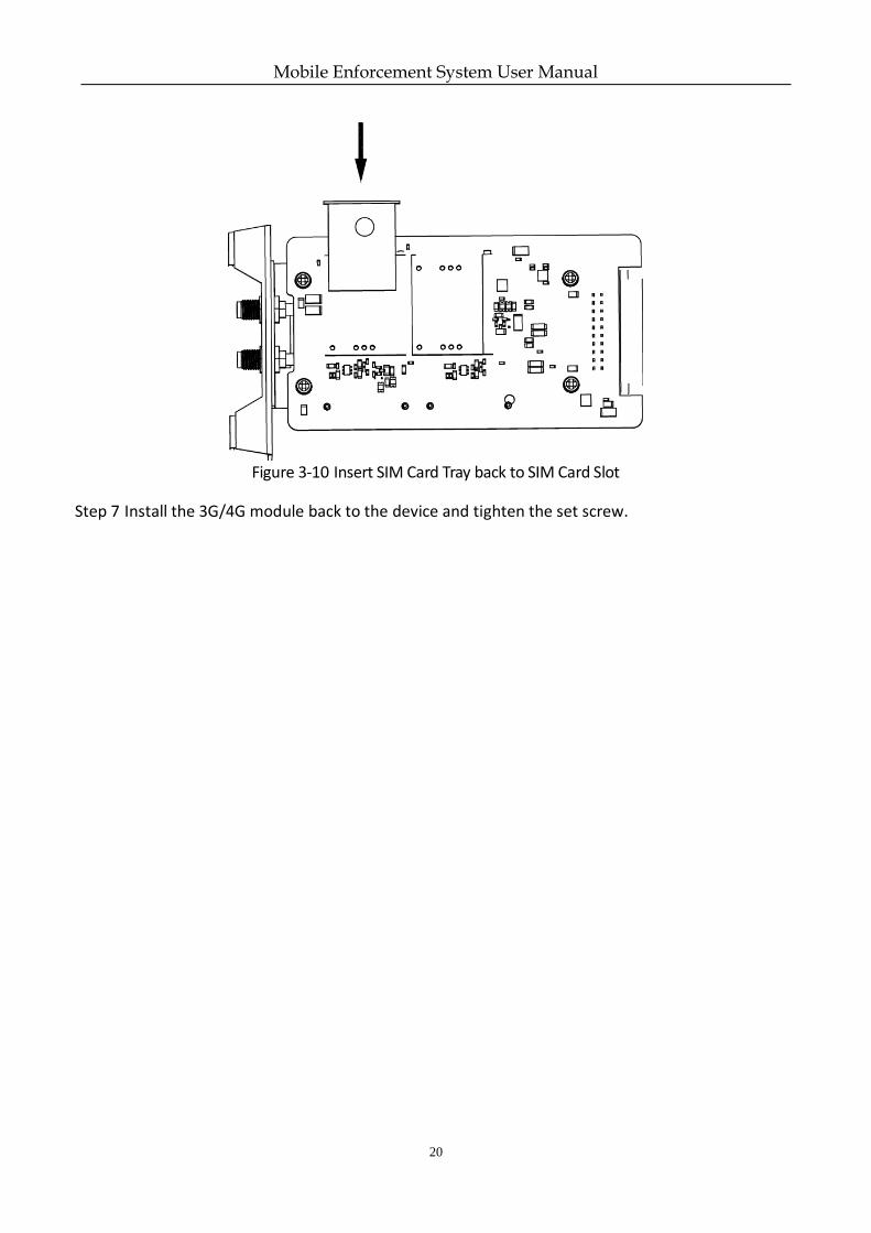
Step 6 Insert the SIM card tray back to SIM card slot.
Mobile Enforcement System User Manual
20
Figure 3-10 Insert SIM Card Tray back to SIM Card Slot
Step 7 Install the 3G/4G module back to the device and tighten the set screw.
Mobile Enforcement System User Manual
21
Chapter 4 Menu Operation
Purpose:
This section introduces manual controller operation, which is often used, to help you improve operation efficiency.
Move the joystick of manual controller upward, downward, leftward and rightward are respectively briefed as press Up, press Down, press Left, and press Right.
The button on the top of the joystick is briefed as OK.
A select box, briefed as cursor will pop up after you enter the system. Press Up, Down, Left or Right, and you can select the menu item as desired with the cursor.
The system provides two input methods, including English and Digital. Select the item with the cursor and press OK to enter the editing status. Press Up to switch the input method, and input the parameters with the numeric buttons. Press Down to delete the input characters. Press OK to confirm the settings after completing the inputs.
Numeric buttons can be used as shortcuts in menu operation. Details are described in Chapter 4 Menu Operation.
4.1 Enter Main Menu
Step 1 Hold till you hear a single beep sound and the button turns red.
4.2 Enter Sub-Menu
Step 1 Enter main menu interface.
Step 2 Double click the numeric button that representing a sub-menu.
For example, double click to enter enforce settings interface.
Mobile Enforcement System User Manual
22
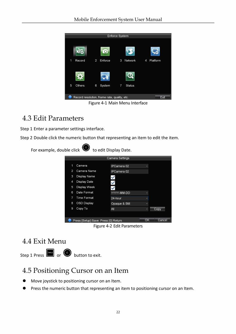
Figure 4-1 Main Menu Interface
4.3 Edit Parameters
Step 1 Enter a parameter settings interface.
Step 2 Double click the numeric button that representing an item to edit the item.
For example, double click to edit Display Date.
Figure 4-2 Edit Parameters
4.4 Exit Menu
Step 1 Press or button to exit.
4.5 Positioning Cursor on an Item
Move joystick to positioning cursor on an Item.
Press the numeric button that representing an item to positioning cursor on an Item.
Mobile Enforcement System User Manual
23
4.6 Check a Checkbox
Step 1 Positioning the cursor on a checkbox.
Step 2 Press OK to check the checkbox.
4.7 Edit Dropdown List
Step 1 Positioning the cursor on a dropdown list.
Step 2 Press OK to pop up dropdown list.
Step 3 Press Up/Down to select an option.
Step 4 Press OK to confirm.
4.8 Edit a Text field
Step 1 Positioning the cursor on the text field.
Step 2 Press OK to pop up input method.
Step 3 Input contents.
● Press Up to switch input method.
● Press Down to delete input content.
● Press Left/Right to move cursor between characters.
Step 4 Press OK to exit from editing status.
4.9 Save/Cancel Settings
Press to save settings.
Press to exit without saving.
Mobile Enforcement System User Manual
24
Chapter 5 Start Up Device
5.1 Startup
Before you start:
Install an HDD into the enforcement host, tighten the bolt, and lock the dummy HDD.
Connect the cables correctly.
Step 1 Insert the key into the lock of manual controller, and turn it to ON status.
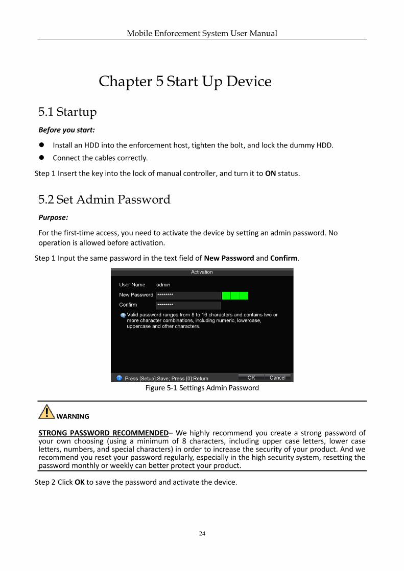
5.2 Set Admin Password
Purpose:
For the first-time access, you need to activate the device by setting an admin password. No operation is allowed before activation.
Step 1 Input the same password in the text field of New Password and Confirm.
Figure 5-1 Settings Admin Password
STRONG PASSWORD RECOMMENDED– We highly recommend you create a strong password of your own choosing (using a minimum of 8 characters, including upper case letters, lower case letters, numbers, and special characters) in order to increase the security of your product. And we recommend you reset your password regularly, especially in the high security system, resetting the password monthly or weekly can better protect your product.
Step 2 Click OK to save the password and activate the device.
Mobile Enforcement System User Manual
25
Chapter 6 Network
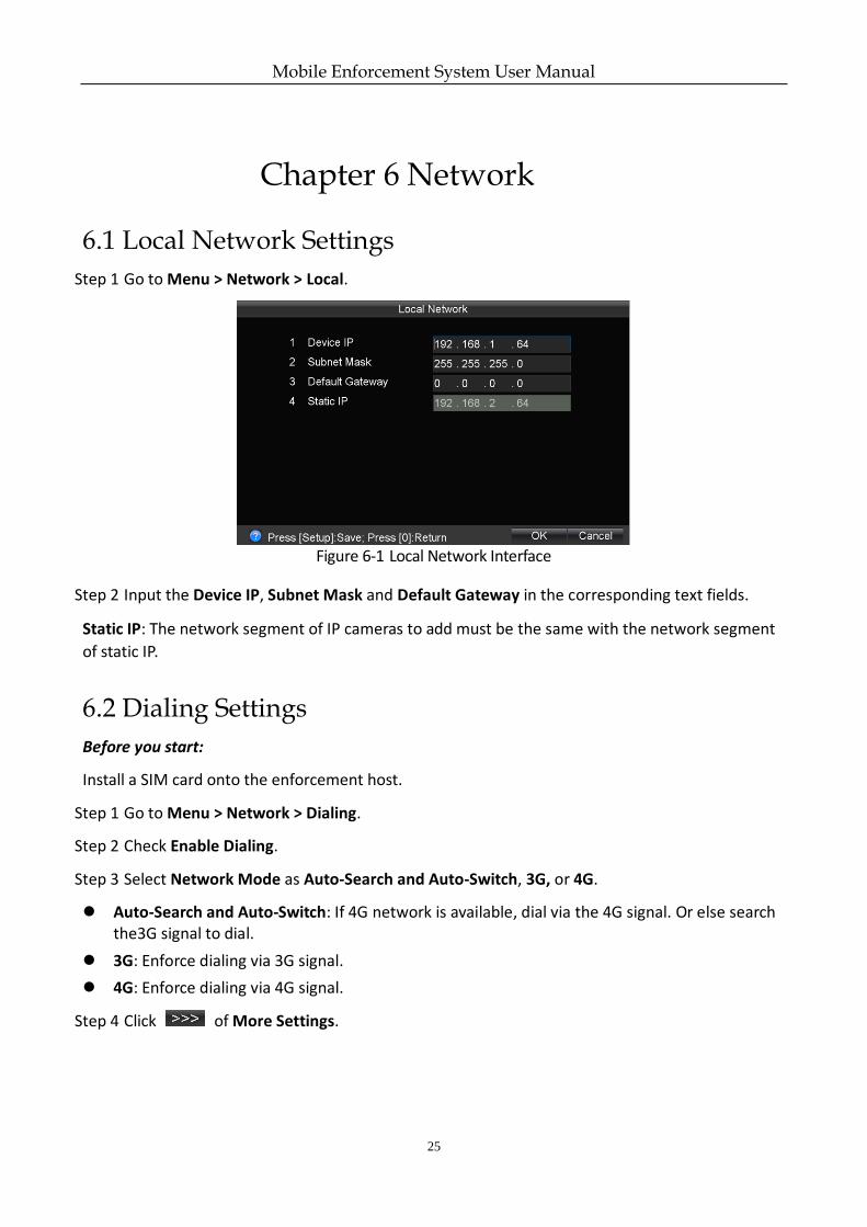
6.1 Local Network Settings
Step 1 Go to Menu > Network > Local.
Figure 6-1 Local Network Interface
Step 2 Input the Device IP, Subnet Mask and Default Gateway in the corresponding text fields.
Static IP: The network segment of IP cameras to add must be the same with the network segment
of static IP.
6.2 Dialing Settings
Before you start:
Install a SIM card onto the enforcement host.
Step 1 Go to Menu > Network > Dialing.
Step 2 Check Enable Dialing.
Step 3 Select Network Mode as Auto-Search and Auto-Switch, 3G, or 4G.
Auto-Search and Auto-Switch: If 4G network is available, dial via the 4G signal. Or else search the3G signal to dial.
3G: Enforce dialing via 3G signal.
4G: Enforce dialing via 4G signal.
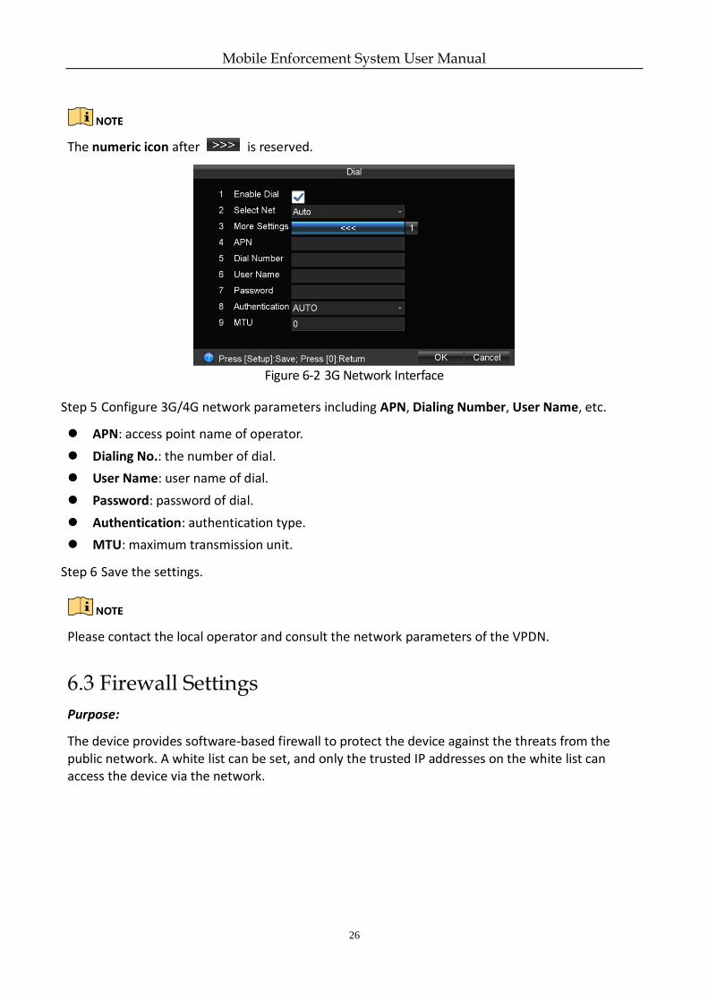
Step 4 Click of More Settings.
Mobile Enforcement System User Manual
26
The numeric icon after is reserved.
Figure 6-2 3G Network Interface
Step 5 Configure 3G/4G network parameters including APN, Dialing Number, User Name, etc.
APN: access point name of operator.
Dialing No.: the number of dial.
User Name: user name of dial.
Password: password of dial.
Authentication: authentication type.
MTU: maximum transmission unit.
Step 6 Save the settings.
Please contact the local operator and consult the network parameters of the VPDN.
6.3 Firewall Settings
Purpose:
The device provides software-based firewall to protect the device against the threats from the public network. A white list can be set, and only the trusted IP addresses on the white list can access the device via the network.
Mobile Enforcement System User Manual
27
192.0.0.xxx is set as the default trusted IP addresses.
The IP address of the platform server to add the device is set as the trusted IP address.
Up to 16 IP addresses can be added on the white list.
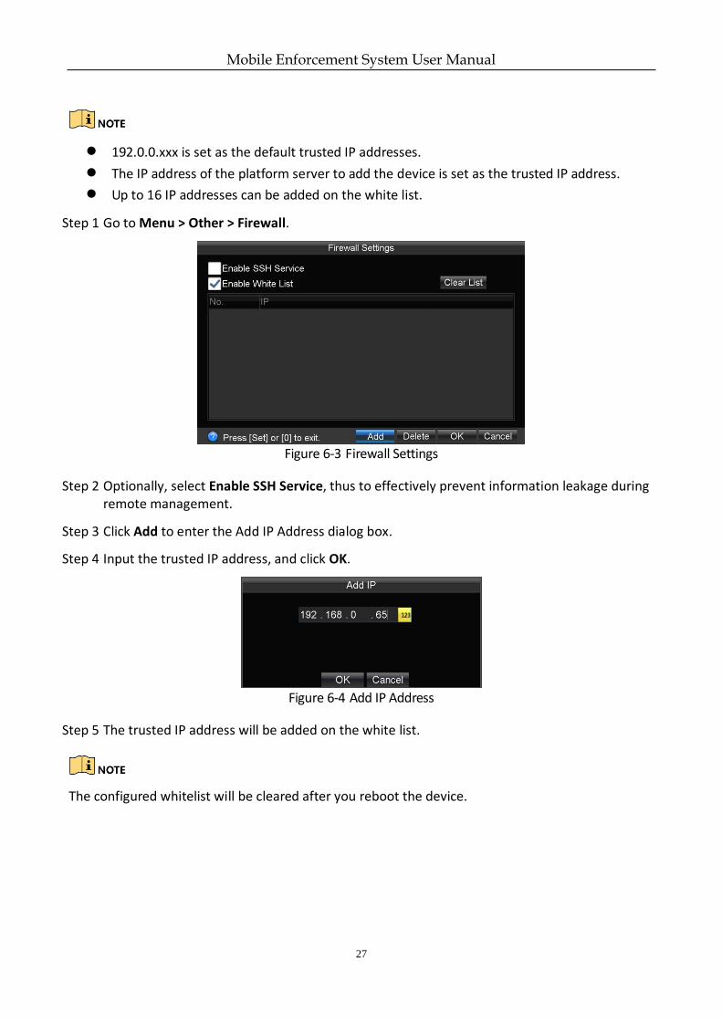
Step 1 Go to Menu > Other > Firewall.
Figure 6-3 Firewall Settings
Step 2 Optionally, select Enable SSH Service, thus to effectively prevent information leakage during remote management.
Step 3 Click Add to enter the Add IP Address dialog box.
Step 4 Input the trusted IP address, and click OK.
Figure 6-4 Add IP Address
Step 5 The trusted IP address will be added on the white list.
The configured whitelist will be cleared after you reboot the device.
Mobile Enforcement System User Manual
28
Chapter 7 IP Camera
Purpose:
Add IP cameras to the device. You can get the live view, record the video, and set the parameters of the connected IP camera.
7.1 Activate IP Camera
Purpose:
Before adding an IP camera, activate it by setting a password for it.
Step 1 Go to Menu > Other > IPC.
Step 2 Uncheck Add Automatically and click .
Step 3 Select an inactivated IP camera.
Step 4 Activate the selected IP camera.
Option 1: Quick Activation
Click Quick Active. The IP camera password will be set as the same with the device password.
Option 2: Manual Activation
1) Click Manu Active.
2) Enter New Password and enter the same password in Confirm.
STRONG PASSWORD RECOMMENDED – We highly recommend you create a strong password of your own choosing (Using a minimum of 8 characters, including at least three of the following categories: upper case letters, lower case letters, numbers, and special characters.) in order to increase the security of your product. And we recommend you reset your password regularly, especially in the high security system, resetting the password monthly or weekly can better protect your product.
Step 5 Click OK.
7.2 Automatically Add IP Camera
Before you start:
Activate the IP camera to configure.
IP camera password must be the same as the one of device.
Mobile Enforcement System User Manual
29
The network segment of IP camera must be 192.168.2.XXX.
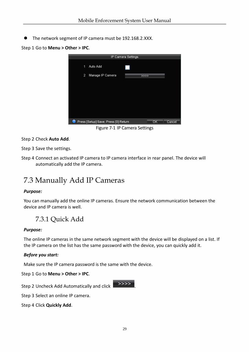
Step 1 Go to Menu > Other > IPC.
Figure 7-1 IP Camera Settings
Step 2 Check Auto Add.
Step 3 Save the settings.
Step 4 Connect an activated IP camera to IP camera interface in rear panel. The device will automatically add the IP camera.
7.3 Manually Add IP Cameras
Purpose:
You can manually add the online IP cameras. Ensure the network communication between the device and IP camera is well.
7.3.1 Quick Add
Purpose:
The online IP cameras in the same network segment with the device will be displayed on a list. If the IP camera on the list has the same password with the device, you can quickly add it.
Before you start:
Make sure the IP camera password is the same with the device.
Step 1 Go to Menu > Other > IPC.
Step 2 Uncheck Add Automatically and click .
Step 3 Select an online IP camera.
Step 4 Click Quickly Add.
Mobile Enforcement System User Manual
30
7.3.2 Manual Add
Step 1 Go to Menu > Other > IPC.
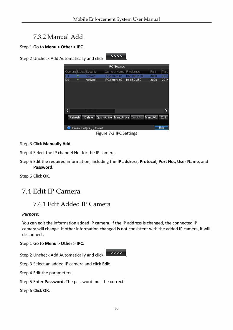
Step 2 Uncheck Add Automatically and click .
Figure 7-2 IPC Settings
Step 3 Click Manually Add.
Step 4 Select the IP channel No. for the IP camera.
Step 5 Edit the required information, including the IP address, Protocol, Port No., User Name, and Password.
Step 6 Click OK.
7.4 Edit IP Camera
7.4.1 Edit Added IP Camera
Purpose:
You can edit the information added IP camera. If the IP address is changed, the connected IP camera will change. If other information changed is not consistent with the added IP camera, it will disconnect.
Step 1 Go to Menu > Other > IPC.
Step 2 Uncheck Add Automatically and click .
Step 3 Select an added IP camera and click Edit.
Step 4 Edit the parameters.
Step 5 Enter Password. The password must be correct.
Step 6 Click OK.
Mobile Enforcement System User Manual
31
7.4.2 Edit Un-Added IP Camera
Purpose:
You can modify the IP address and port of online and un-added IP camera.
Step 1 Go to Menu > Other > IPC.
Step 2 Uncheck Add Automatically and click .
Step 3 Select an un-added IP camera and click Edit.
Step 4 Edit the IP Address or Port.
Step 5 Enter Password. The password must be correct.
Step 6 Click OK.
7.5 Delete IP Cameras
Step 1 Go to Menu > Other > IPC.
Step 2 Uncheck Add Automatically and click .
Step 3 Select an IP camera and click Delete.
Step 4 Click Yes on the pop-up dialog box.
Mobile Enforcement System User Manual
32
Chapter 8 Camera Management
8.1 OSD Settings
Purpose:
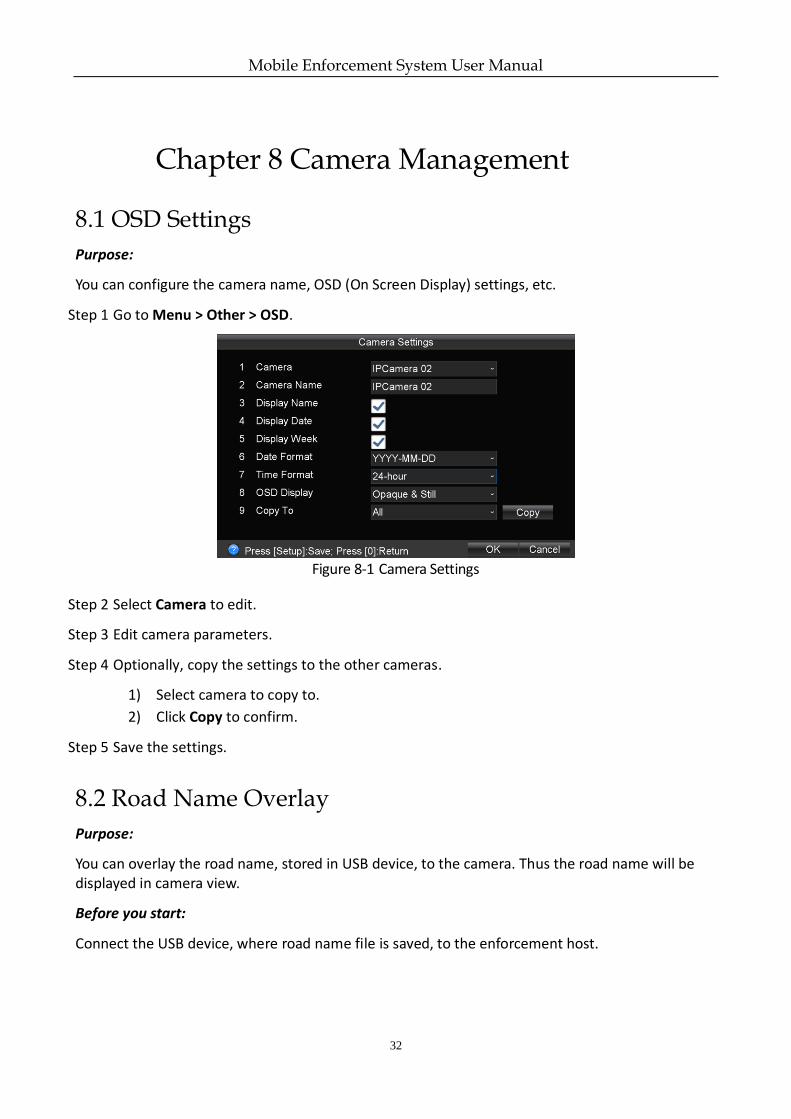
You can configure the camera name, OSD (On Screen Display) settings, etc.
Step 1 Go to Menu > Other > OSD.
Figure 8-1 Camera Settings
Step 2 Select Camera to edit.
Step 3 Edit camera parameters.
Step 4 Optionally, copy the settings to the other cameras.
1) Select camera to copy to.
2) Click Copy to confirm.
Step 5 Save the settings.
8.2 Road Name Overlay
Purpose:
You can overlay the road name, stored in USB device, to the camera. Thus the road name will be displayed in camera view.
Before you start:
Connect the USB device, where road name file is saved, to the enforcement host.
Mobile Enforcement System User Manual
33
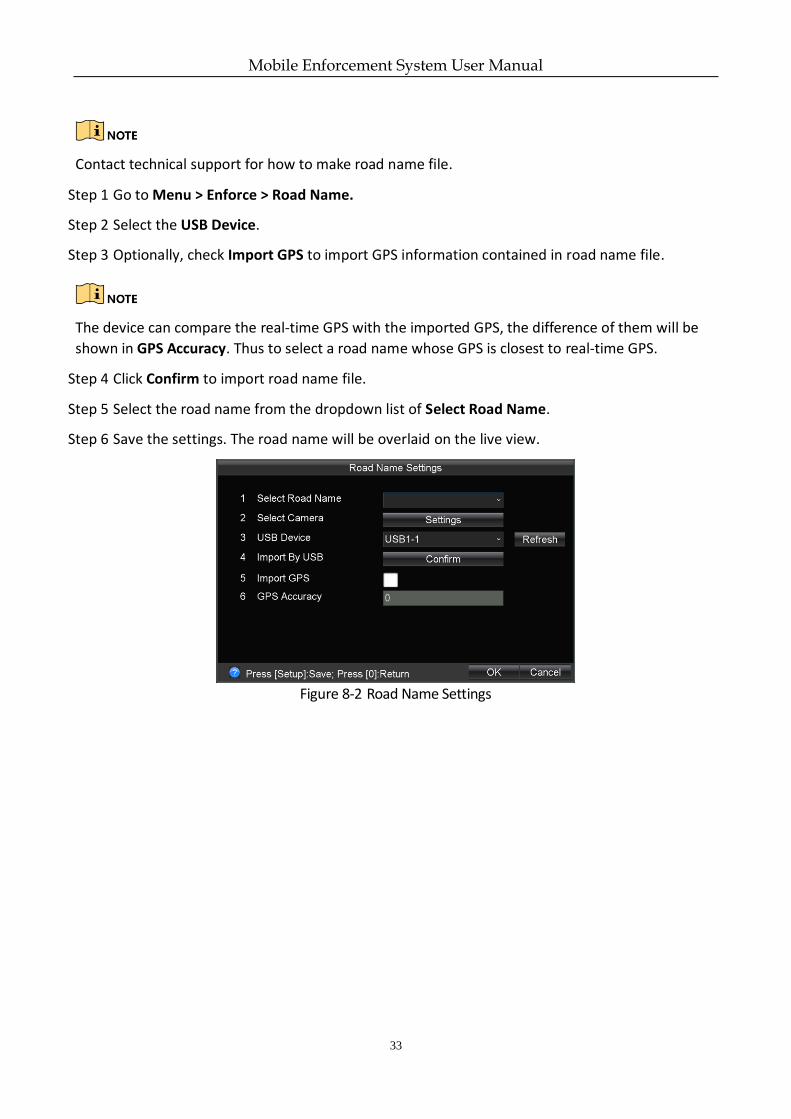
Contact technical support for how to make road name file.
Step 1 Go to Menu > Enforce > Road Name.
Step 2 Select the USB Device.
Step 3 Optionally, check Import GPS to import GPS information contained in road name file.
The device can compare the real-time GPS with the imported GPS, the difference of them will be
shown in GPS Accuracy. Thus to select a road name whose GPS is closest to real-time GPS.
Step 4 Click Confirm to import road name file.
Step 5 Select the road name from the dropdown list of Select Road Name.
Step 6 Save the settings. The road name will be overlaid on the live view.
Figure 8-2 Road Name Settings
Mobile Enforcement System User Manual
34
Chapter 9 Live View
9.1 PTZ Control Settings
Purpose:
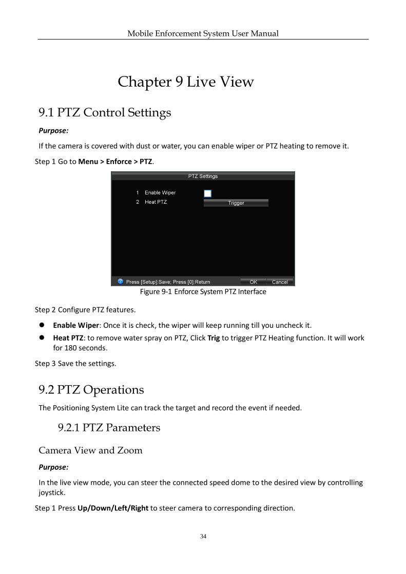
If the camera is covered with dust or water, you can enable wiper or PTZ heating to remove it.
Step 1 Go to Menu > Enforce > PTZ.
Figure 9-1 Enforce System PTZ Interface
Step 2 Configure PTZ features.
Enable Wiper: Once it is check, the wiper will keep running till you uncheck it.
Heat PTZ: to remove water spray on PTZ, Click Trig to trigger PTZ Heating function. It will work for 180 seconds.
Step 3 Save the settings.
9.2 PTZ Operations
The Positioning System Lite can track the target and record the event if needed.
9.2.1 PTZ Parameters
Camera View and Zoom
Purpose:
In the live view mode, you can steer the connected speed dome to the desired view by controlling joystick.
Step 1 Press Up/Down/Left/Right to steer camera to corresponding direction.
Mobile Enforcement System User Manual
35
The more you title the joystick, the faster the PTZ moves.
Step 2 Rotate the joystick clockwise to zoom in. Rotate the joystick anticlockwise to zoom out.
The PTZ speed slows down while zooming in. Conversely, the PTZ speeds up while zooming out.
Shutter
Purpose:
The vehicle speed and driving environment cause effect on the video quality. Image tail and unstable focus may occur when the target moves fast. You can adjust the shutter speed of the camera to lower these negative effects.
It is recommended to set the shutter speed to high level in the daytime of fine weather
days.
When the image quality is acceptable, it is recommended to set the shutter speed as high
as possible.
Step 1 Press to switch shutter to auto, low, medium, or high speed.
The indicator status of represents different shutter speed.
Unlit: Auto. Device adjusts shutter automatically.
Solid green: Low speed. It is applicable to dark environment or situation in which the
vehicle speed is under 20km/h.
Blinking with green light and low frequency: Medium speed. It is applicable to normal
environment or situation in which the vehicle speed is between 20km/h to 60km/h.
Blinking with green light and high frequency: High speed. It is applicable to bright
environment or situation in which the vehicle speed is over 60km/h.
Focus
Purpose:
In default situation, enforcement host will automatically adjust focus. If necessary, you can adjust the focus manually.
Step 1 Press till the indicator goes out, thus to enable manually focus.
Step 2 Press to focus on far view. Or press to focus on near view.
Mobile Enforcement System User Manual
36
Step 3 Press to enable auto focus.
Iris
Purpose:
In live view mode, you can lighten/darken camera by enlarging or lessening iris.
Step 1 Press-and-hold button till you hear a single beep sound. And the indicator turns
blinking green. Or press button. And the indicator turns solid orange.
Step 2 Press to enlarge iris. Or press to lessen iris.
Day/Night Switch
Purpose:
In night or dark environment, you can turn on supplement light of mobile PTZ to ensure the quality of camera view.
Step 1 Press button on manual controller and the indicator turns orange. Thus supplement light is enabled.
Step 2 Press button again and the indicator turns off. Thus supplement light is disabled.
Wiper
Purpose:
If the PTZ lens is covered with dust or raindrops, which influence camera view, you can use wiper to remove it.
Steps for manual controller:
Step 1 In the live view mode, press to enable wiper. Then the wiper will run for one round.
Steps for monitor:
Step 2 Go to Menu > Enforce > PTZ.
Mobile Enforcement System User Manual
37
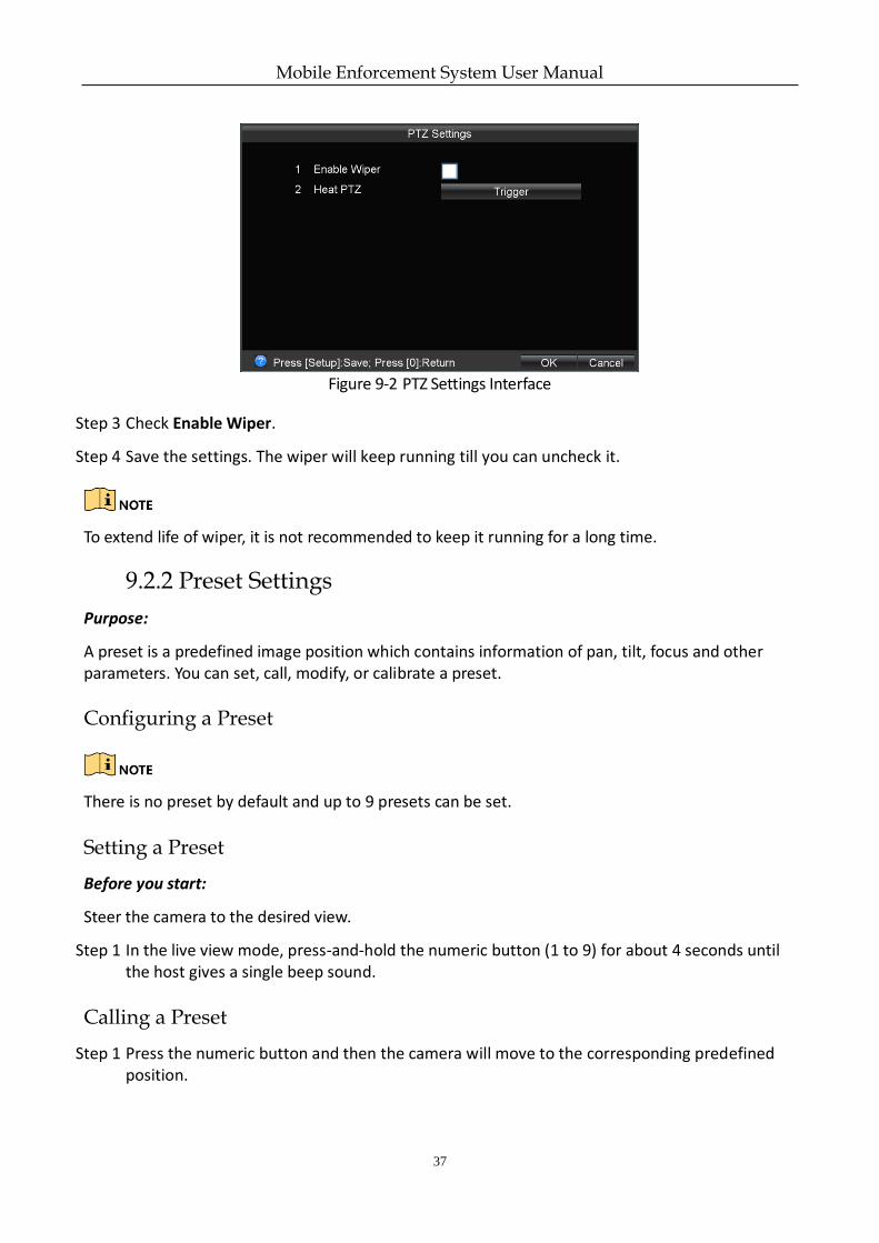
Figure 9-2 PTZ Settings Interface
Step 3 Check Enable Wiper.
Step 4 Save the settings. The wiper will keep running till you can uncheck it.
To extend life of wiper, it is not recommended to keep it running for a long time.
9.2.2 Preset Settings
Purpose:
A preset is a predefined image position which contains information of pan, tilt, focus and other parameters. You can set, call, modify, or calibrate a preset.
Configuring a Preset
There is no preset by default and up to 9 presets can be set.
Setting a Preset
Before you start:
Steer the camera to the desired view.
Step 1 In the live view mode, press-and-hold the numeric button (1 to 9) for about 4 seconds until the host gives a single beep sound.
Calling a Preset
Step 1 Press the numeric button and then the camera will move to the corresponding predefined position.
Mobile Enforcement System User Manual
38
Editing a Preset
Step 1 Repeat the steps in Section Setting a Preset for a certain preset, the previous position will be covered by the new one.
Calibrating a Preset
Due to the intense vibration during vehicle travelling or the influence of other outside forces, the preset of the Positioning System Lite may be out of alignment. It is recommended to give a regular calibration to the presets of the camera.
Two types of methods are provided to calibrate the preset:
Power on the system again.
Rotate the Positioning System Lite at least one circle.
Mobile Enforcement System User Manual
39
Chapter 10 HDD Management
Purpose:
You can set the recording overwrite mode, view the status, free space and total capacity of the storage device, and format the storage device.
Before you start:
Install at least a HDD on the enforcement host for data storage.
10.1.1 Format HDD
Step 1 Go to Menu > System > Hard Disk.
Step 2 Enter password in the text field to get authorization and click OK.
Step 3 Select a Storage Device to format.
Step 4 Click Format.
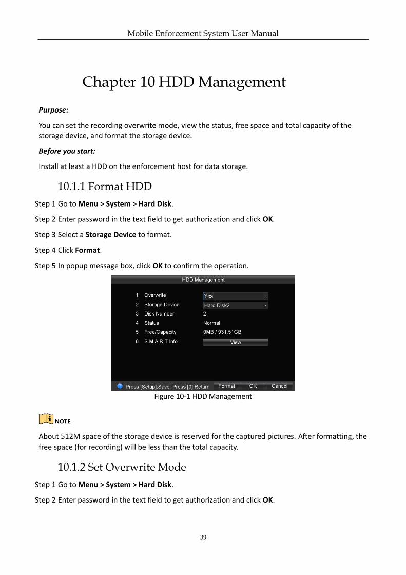
Step 5 In popup message box, click OK to confirm the operation.
Figure 10-1 HDD Management
About 512M space of the storage device is reserved for the captured pictures. After formatting, the
free space (for recording) will be less than the total capacity.
10.1.2 Set Overwrite Mode
Step 1 Go to Menu > System > Hard Disk.
Step 2 Enter password in the text field to get authorization and click OK.
Mobile Enforcement System User Manual
40
Step 3 Select Overwrite as Yes or No.
Yes: The history videos will be overwritten when HDD is full.
No: The recording will stop when HDD is full. If the HDD full alarm is enabled, the system will send out linkage alarm action when the HDD is full.
Step 4 Save the settings.
10.1.3 View S.M.A.R.T Information
Step 1 Go to Menu > System > Hard Disk.
Step 2 Enter password in the text field to get authorization and click OK.
Step 3 Select a Storage Device to format.
Step 4 Click View of S.M.A.R.T Info.
Mobile Enforcement System User Manual
41
Chapter 11 Recording and Capture
11.1 Record Parameters
Purpose:
You can configure record parameters, which directly influence the quality of record image. Generally, it is recommended to use the default settings.
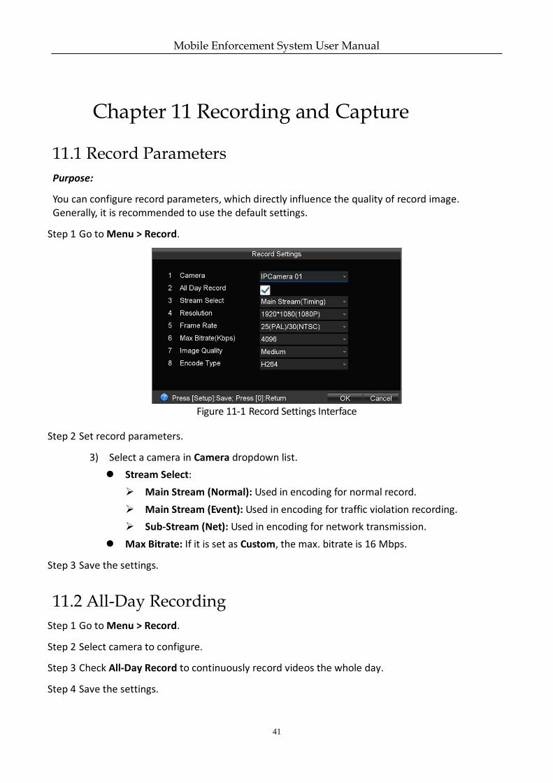
Step 1 Go to Menu > Record.
Figure 11-1 Record Settings Interface
Step 2 Set record parameters.
3) Select a camera in Camera dropdown list.
Stream Select:
Main Stream (Normal): Used in encoding for normal record.
Main Stream (Event): Used in encoding for traffic violation recording.
Sub-Stream (Net): Used in encoding for network transmission.
Max Bitrate: If it is set as Custom, the max. bitrate is 16 Mbps.
Step 3 Save the settings.
11.2 All-Day Recording
Step 1 Go to Menu > Record.
Step 2 Select camera to configure.
Step 3 Check All-Day Record to continuously record videos the whole day.
Step 4 Save the settings.
Mobile Enforcement System User Manual
42
11.3 Manual Recording
Step 1 Enter live view mode.
Step 2 Hold the Record button for 2 seconds to start manual recording and the indicator turns red.
Step 3 Hold the Record button for 2 seconds to stop manual recording and the indicator turns off.
All-day recording stops when manual recording starts. All-day recording resumes when manual
recording stops.
11.4 Manual Capture
Step 1 Go to Menu > Enforce > Capture.
Step 2 Select Channel as needed and check Enable Capture.
Step 3 Save the settings.
Step 4 Enter live view mode.
Step 5 Press OK to capture one picture.
Mobile Enforcement System User Manual
43
Chapter 12 Traffic Violation Operations
12.1 Traffic Violation Recording
Purpose:
You can record traffic violation videos. The function is only available for positioning system lite (channel 1).
12.1.1 Set Traffic Violation
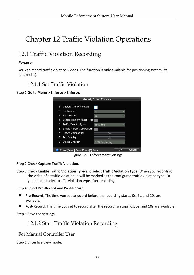
Step 1 Go to Menu > Enforce > Enforce.
Figure 12-1 Enforcement Settings
Step 2 Check Capture Traffic Violation.
Step 3 Check Enable Traffic Violation Type and select Traffic Violation Type. When you recording the video of a traffic violation, it will be marked as the configured traffic violation type. Or you need to select traffic violation type after recording.
Step 4 Select Pre-Record and Post-Record.
Pre-Record: The time you set to record before the recording starts. 0s, 5s, and 10s are available.
Post-Record: The time you set to record after the recording stops. 0s, 5s, and 10s are available.
Step 5 Save the settings.
12.1.2 Start Traffic Violation Recording
For Manual Controller User
Step 1 Enter live view mode.
Mobile Enforcement System User Manual
44
Step 2 Hold the Record button for 2 seconds to start manual recording.
Step 3 Hold the OK button for 2 seconds to start traffic violation recording.
Step 4 If Enable Picture Composition is unchecked and Enable Traffic Violation Type is checked, select traffic, hold the OK button for 2 seconds to stop traffic violation recording.
If both Enable Picture Composition and Enable Traffic Violation Type are unchecked, select traffic, hold the OK button for 2 seconds to stop traffic violation recording and select traffic violation type.
If Enable Picture Composition is checked, press OK to capture till the captured picture number reaches the Number of Pictures set in 12.3.1 Picture Composition Parameters.
For Touchscreen User
Step 1 Enter live view mode.
Step 2 Tap Record to start manual recording.
Step 3 Tap Mark to start traffic violation recording.
Step 4 If Enable Picture Composition is unchecked and Enable Traffic Violation Type is checked, select traffic, tap Exit to stop traffic violation recording.
If both Enable Picture Composition and Enable Traffic Violation Type are unchecked, select traffic, tap Exit to stop traffic violation recording and select traffic violation type.
If Enable Picture Composition is checked, tap Exit to capture till the captured picture number reaches the Number of Pictures set in 10.8.1 Picture Composition Parameters.
12.2 Traffic Violation Capture
Purpose:
During traffic violation recording, you can capture the picture of traffic violation scene. The function is only available for positioning system lite (channel 1).
12.2.1 Set Traffic Violation Capture Parameters
Purpose:
You can capture traffic violation.
Step 1 Go to Menu > Enforce > Capture.
Mobile Enforcement System User Manual
45
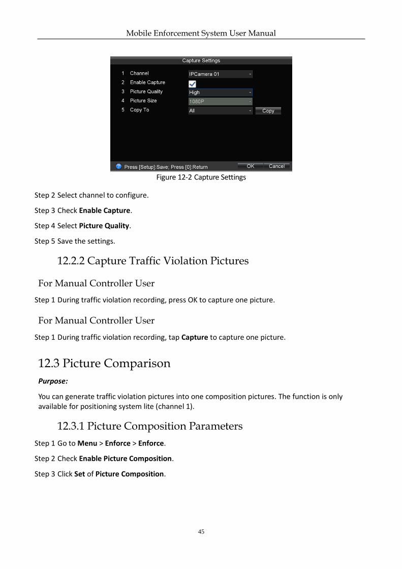
Figure 12-2 Capture Settings
Step 2 Select channel to configure.
Step 3 Check Enable Capture.
Step 4 Select Picture Quality.
Step 5 Save the settings.
12.2.2 Capture Traffic Violation Pictures
For Manual Controller User
Step 1 During traffic violation recording, press OK to capture one picture.
For Manual Controller User
Step 1 During traffic violation recording, tap Capture to capture one picture.
12.3 Picture Comparison
Purpose:
You can generate traffic violation pictures into one composition pictures. The function is only available for positioning system lite (channel 1).
12.3.1 Picture Composition Parameters
Step 1 Go to Menu > Enforce > Enforce.
Step 2 Check Enable Picture Composition.
Step 3 Click Set of Picture Composition.

Mobile Enforcement System User Manual
46
Figure 12-3 Picture Composition Settings
Step 4 Configure composition picture options.
Step 5 Click Set of Text Overlay.
Step 6 Select the information to overlay on composition picture.
Step 7 Save the settings.
12.3.2 Start Picture Composition
Step 1 Enter live view mode.
Step 2 Start traffic violation recording.
Step 3 Press OK to capture.
Device will exit traffic violation till the captured picture number reaches the Number of Pictures set in 12.3.1 Picture Composition Parameters.
You can search the composited pictures in playback menu.
Mobile Enforcement System User Manual
47
Chapter 13 Playback
Purpose:
The videos and captured pictures can be played back.
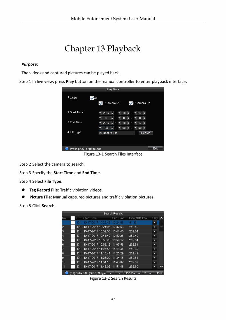
Step 1 In live view, press Play button on the manual controller to enter playback interface.
Figure 13-1 Search Files Interface
Step 2 Select the camera to search.
Step 3 Specify the Start Time and End Time.
Step 4 Select File Type.
Tag Record File: Traffic violation videos.
Picture File: Manual captured pictures and traffic violation pictures.
Step 5 Click Search.
Figure 13-2 Search Results
Mobile Enforcement System User Manual
48
Step 6 Select the file to play and press OK.
The playback toolbar is only available for touchscreen.
Mobile Enforcement System User Manual
49
Chapter 14 Platform
Purpose:
You can connect the device to the Ehome platform for central management.
Before you start:
Register the device ID on Ehome platform.
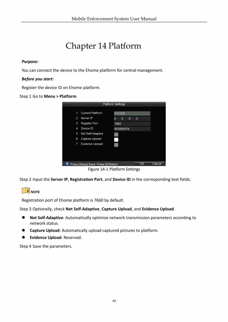
Step 1 Go to Menu > Platform.
Figure 14-1 Platform Settings
Step 2 Input the Server IP, Registration Port, and Device ID in the corresponding text fields.
Registration port of Ehome platform is 7660 by default.
Step 3 Optionally, check Net Self-Adaptive, Capture Upload, and Evidence Upload.
Net Self-Adaptive: Automatically optimize network transmission parameters according to network status.
Capture Upload: Automatically upload captured pictures to platform.
Evidence Upload: Reserved.
Step 4 Save the parameters.
Mobile Enforcement System User Manual
50
Chapter 15 Backup
Purpose:
You can export the videos or pictures stored on the system to the backup device such as a USB flash disk.
Before you start:
Connect a backup device to the device.
Step 1 Search the record files or pictures. For details, see Chapter 13 Step 1 to Step 5.
Step 2 Press to check files to export.
You can also hold until sends out a beep sound to select all videos.
Step 3 Click Export.
Mobile Enforcement System User Manual
51
Chapter 16 Events and Alarms
16.1 Exception Settings
Purpose:
Exception settings refer to the handling action of various exceptions.
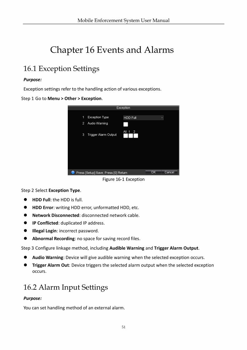
Step 1 Go to Menu > Other > Exception.
Figure 16-1 Exception
Step 2 Select Exception Type.
HDD Full: the HDD is full.
HDD Error: writing HDD error, unformatted HDD, etc.
Network Disconnected: disconnected network cable.
IP Conflicted: duplicated IP address.
Illegal Login: incorrect password.
Abnormal Recording: no space for saving record files.
Step 3 Configure linkage method, including Audible Warning and Trigger Alarm Output.
Audio Warning: Device will give audible warning when the selected exception occurs.
Trigger Alarm Out: Device triggers the selected alarm output when the selected exception occurs.
16.2 Alarm Input Settings
Purpose:
You can set handling method of an external alarm.
Mobile Enforcement System User Manual
52
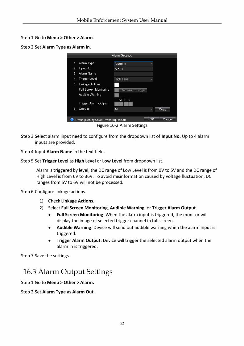
Step 1 Go to Menu > Other > Alarm.
Step 2 Set Alarm Type as Alarm In.
Figure 16-2 Alarm Settings
Step 3 Select alarm input need to configure from the dropdown list of Input No. Up to 4 alarm inputs are provided.
Step 4 Input Alarm Name in the text field.
Step 5 Set Trigger Level as High Level or Low Level from dropdown list.
Alarm is triggered by level, the DC range of Low Level is from 0V to 5V and the DC range of High Level is from 6V to 36V. To avoid misinformation caused by voltage fluctuation, DC ranges from 5V to 6V will not be processed.
Step 6 Configure linkage actions.
1) Check Linkage Actions.
2) Select Full Screen Monitoring, Audible Warning, or Trigger Alarm Output.
● Full Screen Monitoring: When the alarm input is triggered, the monitor will display the image of selected trigger channel in full screen.
● Audible Warning: Device will send out audible warning when the alarm input is triggered.
● Trigger Alarm Output: Device will trigger the selected alarm output when the alarm in is triggered.
Step 7 Save the settings.
16.3 Alarm Output Settings
Step 1 Go to Menu > Other > Alarm.
Step 2 Set Alarm Type as Alarm Out.
Mobile Enforcement System User Manual
53
Figure 16-3 Alarm Settings
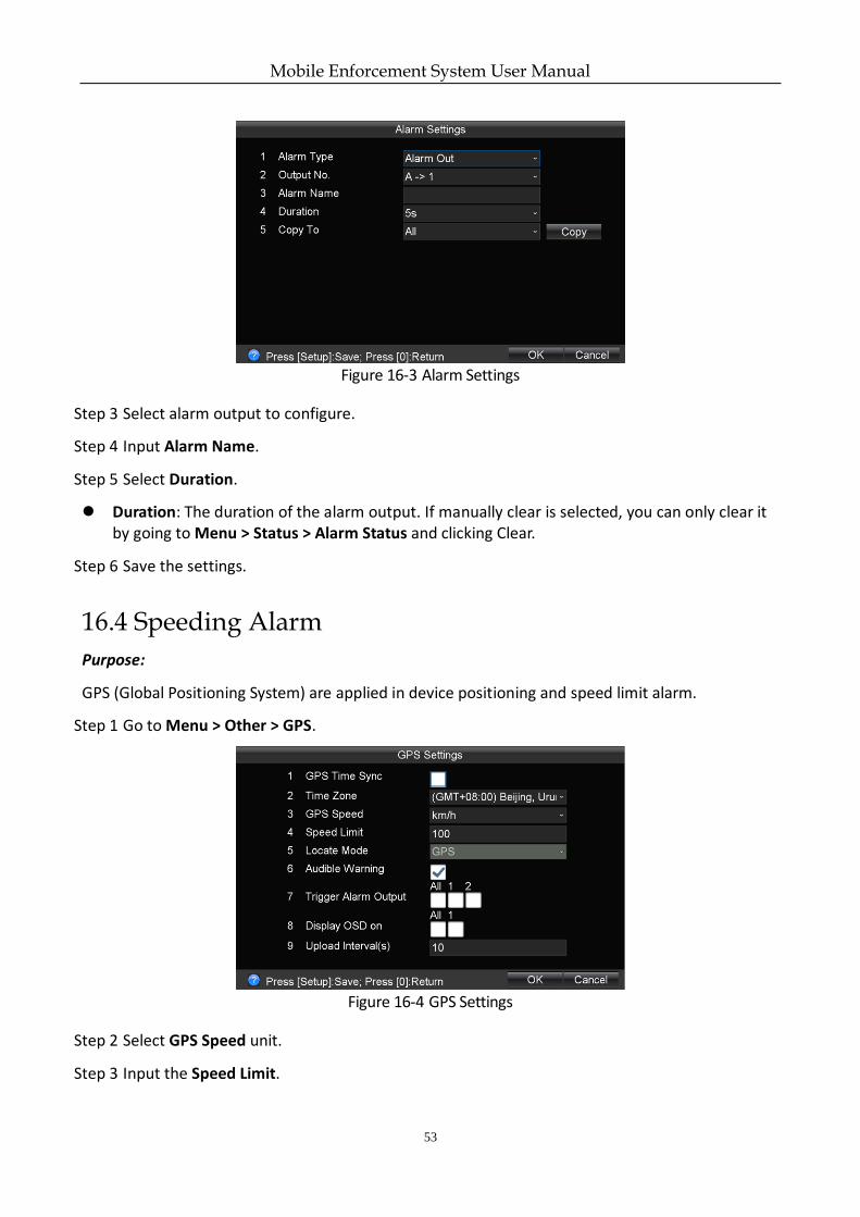
Step 3 Select alarm output to configure.
Step 4 Input Alarm Name.
Step 5 Select Duration.
Duration: The duration of the alarm output. If manually clear is selected, you can only clear it by going to Menu > Status > Alarm Status and clicking Clear.
Step 6 Save the settings.
16.4 Speeding Alarm
Purpose:
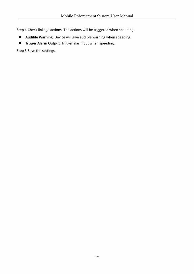
GPS (Global Positioning System) are applied in device positioning and speed limit alarm.
Step 1 Go to Menu > Other > GPS.
Figure 16-4 GPS Settings
Step 2 Select GPS Speed unit.
Step 3 Input the Speed Limit.
Mobile Enforcement System User Manual
54
Step 4 Check linkage actions. The actions will be triggered when speeding.
Audible Warning: Device will give audible warning when speeding.
Trigger Alarm Output: Trigger alarm out when speeding.
Step 5 Save the settings.
Mobile Enforcement System User Manual
55
Chapter 17 User Account Management
Purpose:
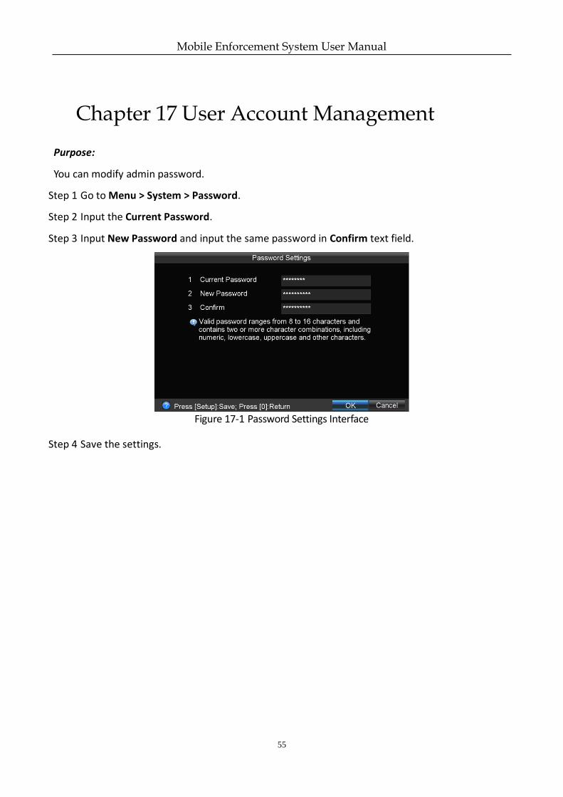
You can modify admin password.
Step 1 Go to Menu > System > Password.
Step 2 Input the Current Password.
Step 3 Input New Password and input the same password in Confirm text field.
Figure 17-1 Password Settings Interface
Step 4 Save the settings.
Mobile Enforcement System User Manual
56
Chapter 18 General System Configuration
18.1 Touchscreen Settings
Purpose:
You can operate device via the connected touchscreen.
Step 1 Go to Menu > Enforce > Touchscreen.
Step 2 Set touchscreen parameters.
Step 3 Save the settings.
Do not connect mouse when using touchscreen.
18.2 GPS Settings
Purpose:
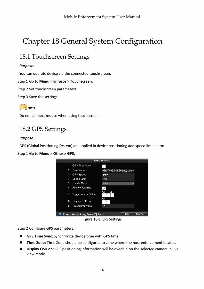
GPS (Global Positioning System) are applied in device positioning and speed limit alarm.
Step 1 Go to Menu > Other > GPS.
Figure 18-1 GPS Settings
Step 2 Configure GPS parameters.
GPS Time Sync: Synchronize device time with GPS time.
Time Zone: Time Zone should be configured to zone where the host enforcement locates.
Display OSD on: GPS positioning information will be overlaid on the selected camera in live view mode.
Mobile Enforcement System User Manual
57
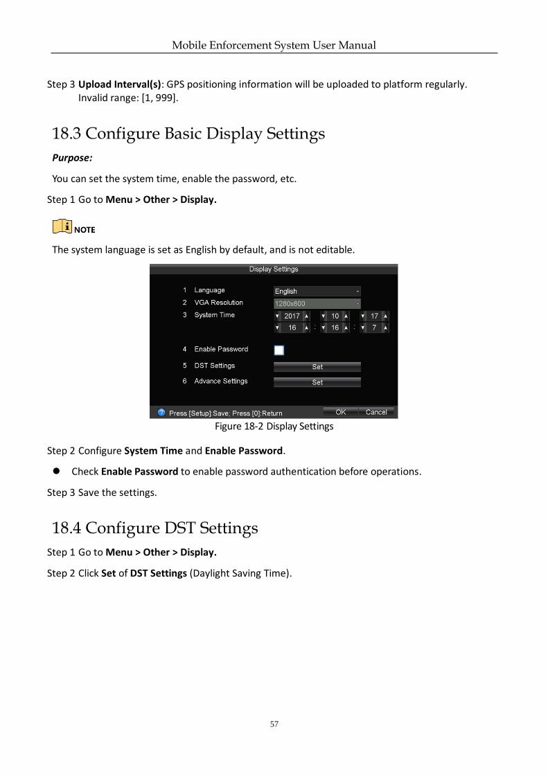
Step 3 Upload Interval(s): GPS positioning information will be uploaded to platform regularly. Invalid range: [1, 999].
18.3 Configure Basic Display Settings
Purpose:
You can set the system time, enable the password, etc.
Step 1 Go to Menu > Other > Display.
The system language is set as English by default, and is not editable.
Figure 18-2 Display Settings
Step 2 Configure System Time and Enable Password.
Check Enable Password to enable password authentication before operations.
Step 3 Save the settings.
18.4 Configure DST Settings
Step 1 Go to Menu > Other > Display.
Step 2 Click Set of DST Settings (Daylight Saving Time).
Mobile Enforcement System User Manual
58
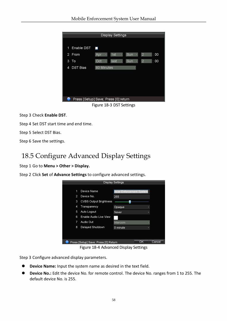
Figure 18-3 DST Settings
Step 3 Check Enable DST.
Step 4 Set DST start time and end time.
Step 5 Select DST Bias.
Step 6 Save the settings.
18.5 Configure Advanced Display Settings
Step 1 Go to Menu > Other > Display.
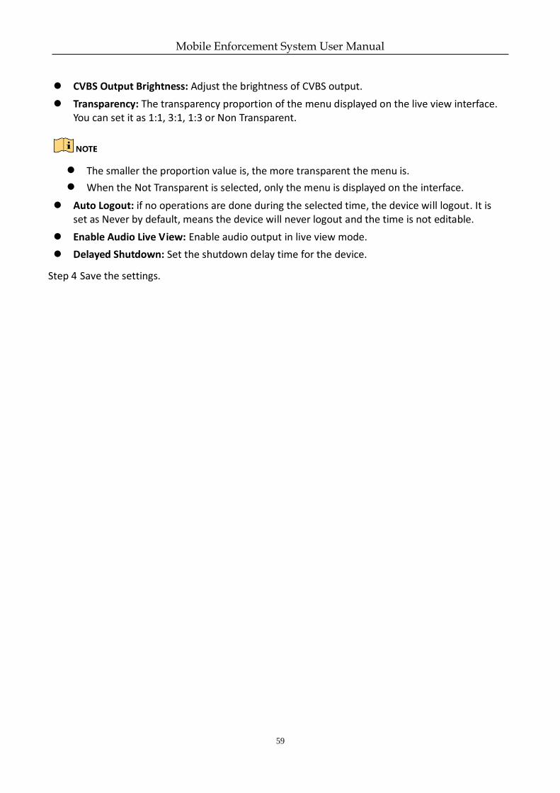
Step 2 Click Set of Advance Settings to configure advanced settings.
Figure 18-4 Advanced Display Settings
Step 3 Configure advanced display parameters.
Device Name: Input the system name as desired in the text field.
Device No.: Edit the device No. for remote control. The device No. ranges from 1 to 255. The default device No. is 255.
Mobile Enforcement System User Manual
59
CVBS Output Brightness: Adjust the brightness of CVBS output.
Transparency: The transparency proportion of the menu displayed on the live view interface. You can set it as 1:1, 3:1, 1:3 or Non Transparent.
The smaller the proportion value is, the more transparent the menu is.
When the Not Transparent is selected, only the menu is displayed on the interface.
Auto Logout: if no operations are done during the selected time, the device will logout. It is set as Never by default, means the device will never logout and the time is not editable.
Enable Audio Live View: Enable audio output in live view mode.
Delayed Shutdown: Set the shutdown delay time for the device.
Step 4 Save the settings.
Mobile Enforcement System User Manual
60
Chapter 19 Maintenance
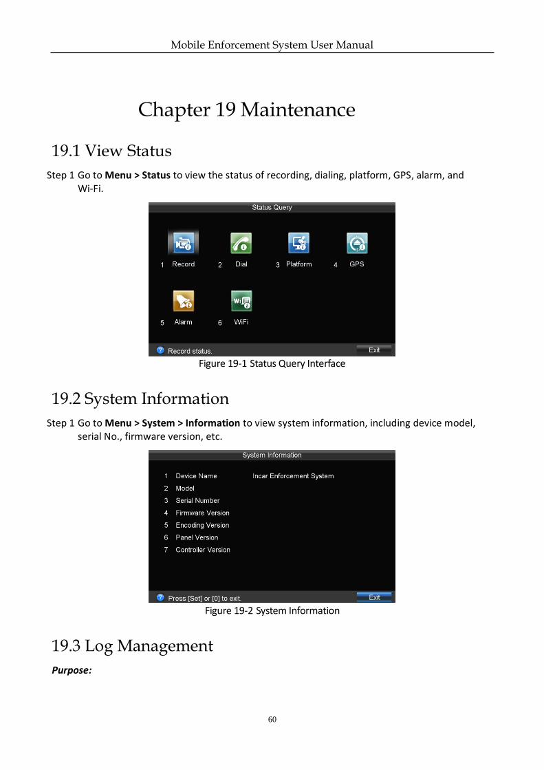
19.1 View Status
Step 1 Go to Menu > Status to view the status of recording, dialing, platform, GPS, alarm, and Wi-Fi.
Figure 19-1 Status Query Interface
19.2 System Information
Step 1 Go to Menu > System > Information to view system information, including device model, serial No., firmware version, etc.
Figure 19-2 System Information
19.3 Log Management
Purpose:
Mobile Enforcement System User Manual
61
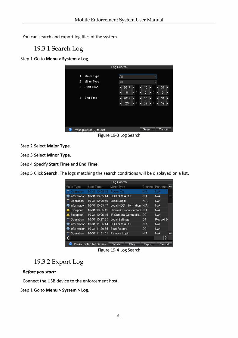
You can search and export log files of the system.
19.3.1 Search Log
Step 1 Go to Menu > System > Log.
Figure 19-3 Log Search
Step 2 Select Major Type.
Step 3 Select Minor Type.
Step 4 Specify Start Time and End Time.
Step 5 Click Search. The logs matching the search conditions will be displayed on a list.
Figure 19-4 Log Search
19.3.2 Export Log
Before you start:
Connect the USB device to the enforcement host,
Step 1 Go to Menu > System > Log.
Mobile Enforcement System User Manual
62
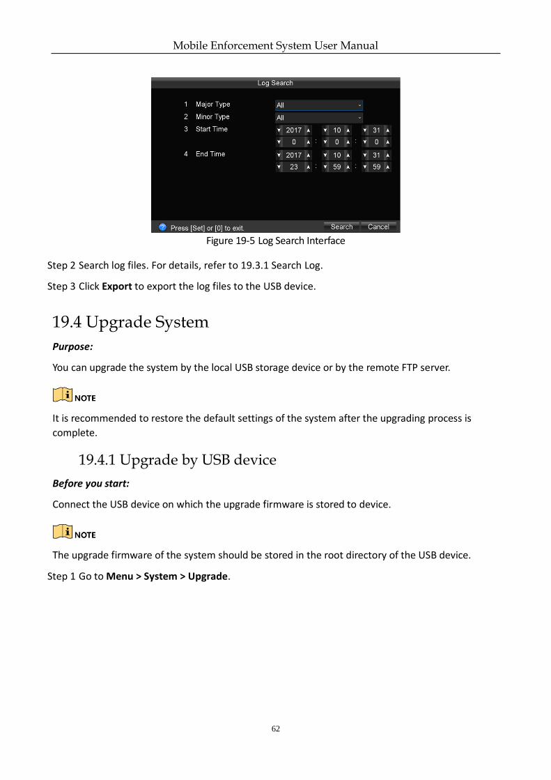
Figure 19-5 Log Search Interface
Step 2 Search log files. For details, refer to 19.3.1 Search Log.
Step 3 Click Export to export the log files to the USB device.
19.4 Upgrade System
Purpose:
You can upgrade the system by the local USB storage device or by the remote FTP server.
It is recommended to restore the default settings of the system after the upgrading process is
complete.
19.4.1 Upgrade by USB device
Before you start:
Connect the USB device on which the upgrade firmware is stored to device.
The upgrade firmware of the system should be stored in the root directory of the USB device.
Step 1 Go to Menu > System > Upgrade.
Mobile Enforcement System User Manual
63
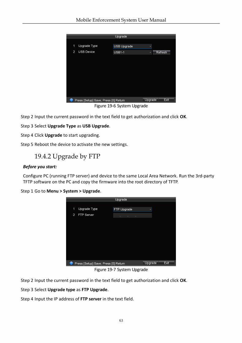
Figure 19-6 System Upgrade
Step 2 Input the current password in the text field to get authorization and click OK.
Step 3 Select Upgrade Type as USB Upgrade.
Step 4 Click Upgrade to start upgrading.
Step 5 Reboot the device to activate the new settings.
19.4.2 Upgrade by FTP
Before you start:
Configure PC (running FTP server) and device to the same Local Area Network. Run the 3rd-party TFTP software on the PC and copy the firmware into the root directory of TFTP.
Step 1 Go to Menu > System > Upgrade.
Figure 19-7 System Upgrade
Step 2 Input the current password in the text field to get authorization and click OK.
Step 3 Select Upgrade type as FTP Upgrade.
Step 4 Input the IP address of FTP server in the text field.
Mobile Enforcement System User Manual
64
Step 5 Click Upgrade to start upgrading.
Step 6 Reboot the device to activate the new settings.
19.5 Restore Default Settings
Purpose:
You can restore the system to factory configuration.
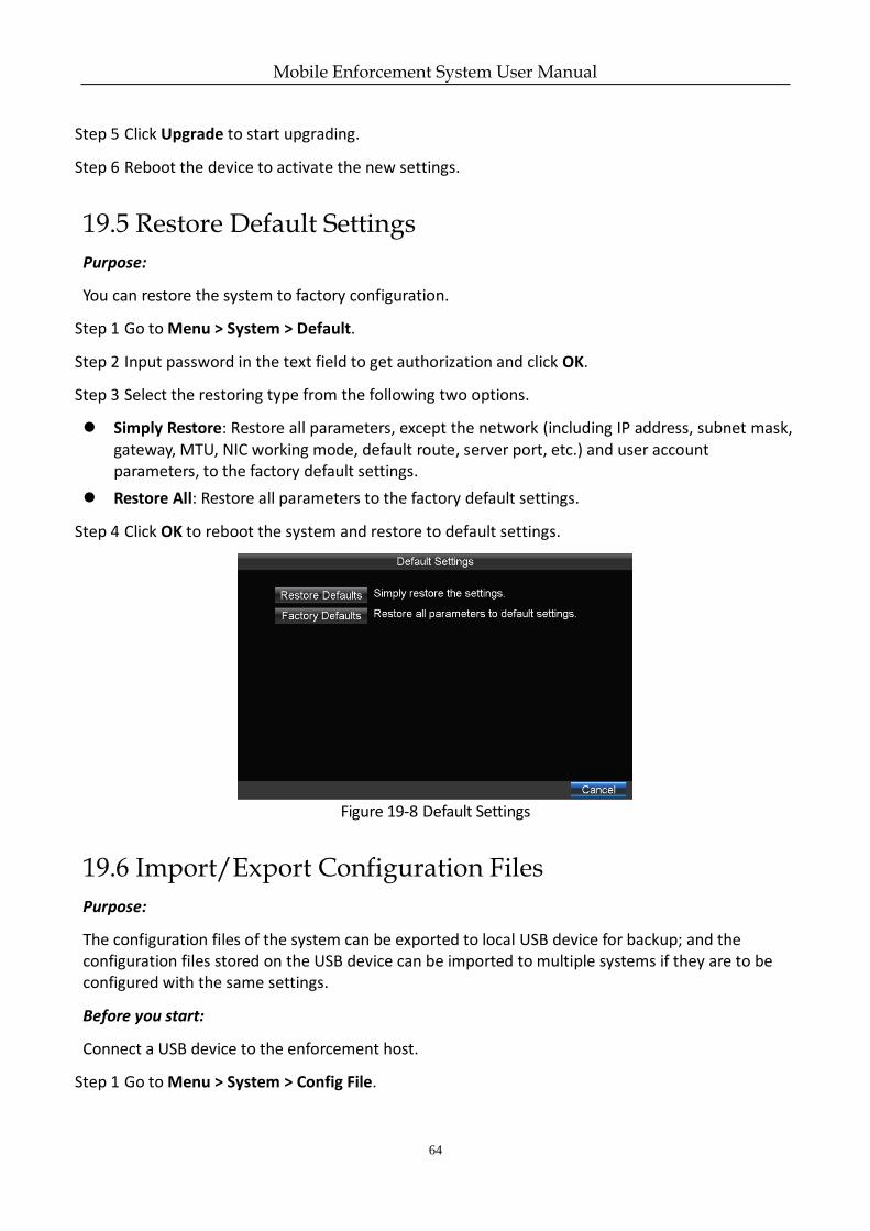
Step 1 Go to Menu > System > Default.
Step 2 Input password in the text field to get authorization and click OK.
Step 3 Select the restoring type from the following two options.
Simply Restore: Restore all parameters, except the network (including IP address, subnet mask, gateway, MTU, NIC working mode, default route, server port, etc.) and user account parameters, to the factory default settings.
Restore All: Restore all parameters to the factory default settings.
Step 4 Click OK to reboot the system and restore to default settings.
Figure 19-8 Default Settings
19.6 Import/Export Configuration Files
Purpose:
The configuration files of the system can be exported to local USB device for backup; and the configuration files stored on the USB device can be imported to multiple systems if they are to be configured with the same settings.
Before you start:
Connect a USB device to the enforcement host.
Step 1 Go to Menu > System > Config File.
Mobile Enforcement System User Manual
65
Step 2 Input the current password in the text field to get authorization and click OK.
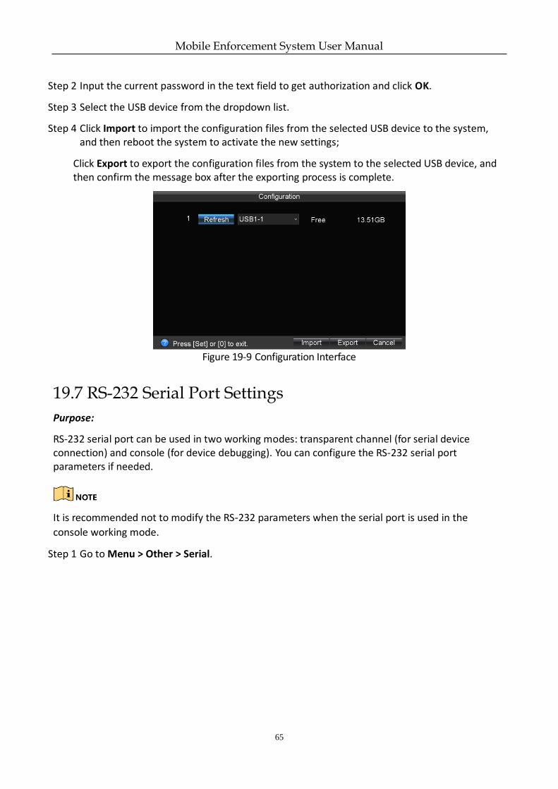
Step 3 Select the USB device from the dropdown list.
Step 4 Click Import to import the configuration files from the selected USB device to the system, and then reboot the system to activate the new settings;
Click Export to export the configuration files from the system to the selected USB device, and then confirm the message box after the exporting process is complete.
Figure 19-9 Configuration Interface
19.7 RS-232 Serial Port Settings
Purpose:
RS-232 serial port can be used in two working modes: transparent channel (for serial device connection) and console (for device debugging). You can configure the RS-232 serial port parameters if needed.
It is recommended not to modify the RS-232 parameters when the serial port is used in the
console working mode.
Step 1 Go to Menu > Other > Serial.
Mobile Enforcement System User Manual
66
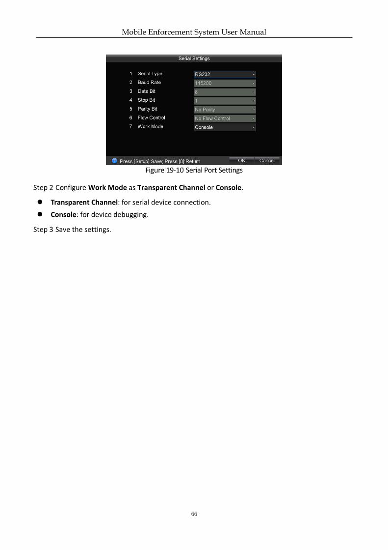
Figure 19-10 Serial Port Settings
Step 2 Configure Work Mode as Transparent Channel or Console.
Transparent Channel: for serial device connection.
Console: for device debugging.
Step 3 Save the settings.
Mobile Enforcement System User Manual
67
Chapter 20 Shutdown
20.1 Boot Settings
Purpose:
You can set the shutdown delay time (Vehicle Ignition Startup and Shutdown) or specify the startup/shutdown time (Timing On/Off) for the device.
20.1.1 Shutdown Delay
Purpose:
You can set the shutdown delay time for the device.
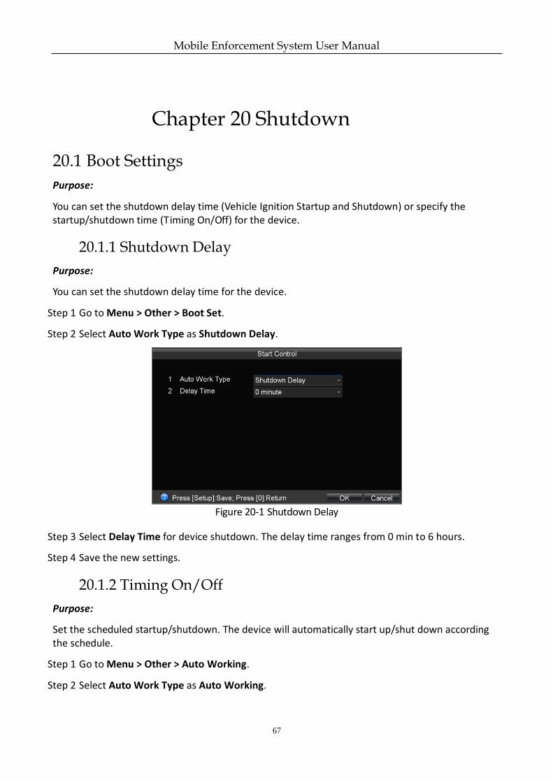
Step 1 Go to Menu > Other > Boot Set.
Step 2 Select Auto Work Type as Shutdown Delay.
Figure 20-1 Shutdown Delay
Step 3 Select Delay Time for device shutdown. The delay time ranges from 0 min to 6 hours.
Step 4 Save the new settings.
20.1.2 Timing On/Off
Purpose:
Set the scheduled startup/shutdown. The device will automatically start up/shut down according the schedule.
Step 1 Go to Menu > Other > Auto Working.
Step 2 Select Auto Work Type as Auto Working.
Mobile Enforcement System User Manual
68
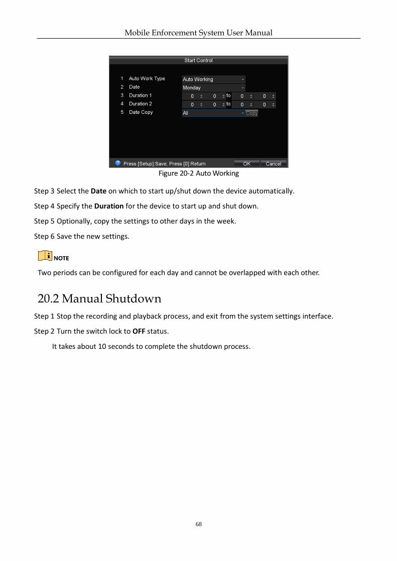
Figure 20-2 Auto Working
Step 3 Select the Date on which to start up/shut down the device automatically.
Step 4 Specify the Duration for the device to start up and shut down.
Step 5 Optionally, copy the settings to other days in the week.
Step 6 Save the new settings.
Two periods can be configured for each day and cannot be overlapped with each other.
20.2 Manual Shutdown
Step 1 Stop the recording and playback process, and exit from the system settings interface.
Step 2 Turn the switch lock to OFF status.
It takes about 10 seconds to complete the shutdown process.
Mobile Enforcement System User Manual
69
Chapter 21 Appendix
21.1 HDD Storage Chart
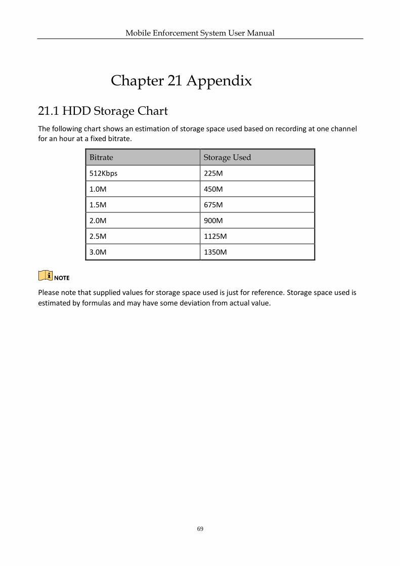
The following chart shows an estimation of storage space used based on recording at one channel for an hour at a fixed bitrate.
Bitrate Storage Used
512Kbps 225M
1.0M 450M
1.5M 675M
2.0M 900M
2.5M 1125M
3.0M 1350M
Please note that supplied values for storage space used is just for reference. Storage space used is
estimated by formulas and may have some deviation from actual value.
Mobile Enforcement System User Manual
70
21.2 Troubleshooting
The new device sends out an audible warning after startup.
Possible Reasons:
a) No storage device (HDD or SD card) is installed on the enforcement host.
b) The installed storage device has not been formatted.
c) The storage device does not work.
Solutions:
a) Install the storage device on the enforcement host or disable the HDD Error alarm on the
Exception Settings interface.
b) Format the storage device.
c) Replace the broken storage device with a new one.
The enforcement host does not respond or restarts repeatedly in the startup process.
Possible Reason:
a) The power supply does not support the system to start up.
The operating voltage of the system ranges from +6VDC to +36VDC. However, the input
voltage and power should be at least 8V and 40W for the system startup.
Solution:
a) Make sure the power supply meets the actual needs of the system.
There is no recording while the system is working properly.
Possible Reasons:
a) No storage device is (HDD or SD card) installed on the enforcement host.
b) The recording function is not enabled.
Solutions:
a) Install the storage device on the enforcement host.
b) Hold-and-press the REC button for about 3 seconds to enable the manual recording; Or check
the checkbox of All-day Record on the Record Settings interface to enable the all-day
recording.
3G dialing failure.
Possible Reasons:
a) The 3G dialing function is not enabled.
b) The 3G VPDN (Virtual Private Dialup Network) parameters, including APN, dialing number,
user name, password and authentication type, are not configured.
c) The 3G antenna is not connected properly.
d) The SIM card number owes a fee or the 3G service is not opened.
Solutions:
Mobile Enforcement System User Manual
71
a) Check the checkbox of Enable 3G on the 3G Network Settings interface to enable the 3G
dialing function.
b) Configure the parameters, including APN, dialing number, user name, password and
authentication type, if 3G VPDN is adopted.
c) Keep the master and slave antennas upright in a distance of at least 20cm if both of them are
installed.
d) Top up the SIM card No. or open the 3G service.
The device is connected to the 3G network, while it cannot be connected to the platform.
Possible Reasons:
a) The input platform parameters, including the server IP address, device ID and so on, are not
correct.
b) The platform server does not work properly.
Solutions:
a) Make sure the input platform parameters are correct.
b) Make sure the database service and other components of the server are working properly.
The locating information of the system cannot be obtained.
Possible Reasons:
a) The GNSS module is not inserted into the enforcement host.
b) The GNSS module is abnormal.
c) There is no satellite positioning signal.
Solutions:
a) Insert the GNSS module into the enforcement host.
b) Make sure the GNSS module works properly.
c) Make sure the GNSS antenna is installed and locate the antenna outdoor or in places with
good signal.
There is no backup device for the record files exporting.
Possible Reasons:
a) No backup device is installed.
b) The backup device is incompatible with the system.
c) The backup device suffers from virus or the format is not correct.
d) The backup device breaks down.
Solutions:
a) Insert the backup device, such as a USB flash drive, on the enforcement host.
b) Replace the backup device with another one which is compatible with the system.
c) Format the backup device and try again.
d) Replace the backup device with a proper-functioning one.
Manually capturing failed.
Possible Reasons:
a) The manual capture function is not enabled.
Mobile Enforcement System User Manual
72
b) The storage device does not work properly.
Solutions:
a) Check the checkbox of Enable Capture on the Enforcement Settings interface to enable the
manual capture function.
b) Make sure the status of the storage device is displayed as Normal on the Storage
Management interface.
The installed HDD (Hard Disk Drive) cannot be recognized.
Possible Reasons:
a) The device has been connected to the computer before system startup. In this situation, the
HDD will be recognized by the computer instead of the device.
b) The HDD does not work properly.
Solutions:
a) Disconnect the device from the computer before system startup.
b) Replace the HDD with a new one.
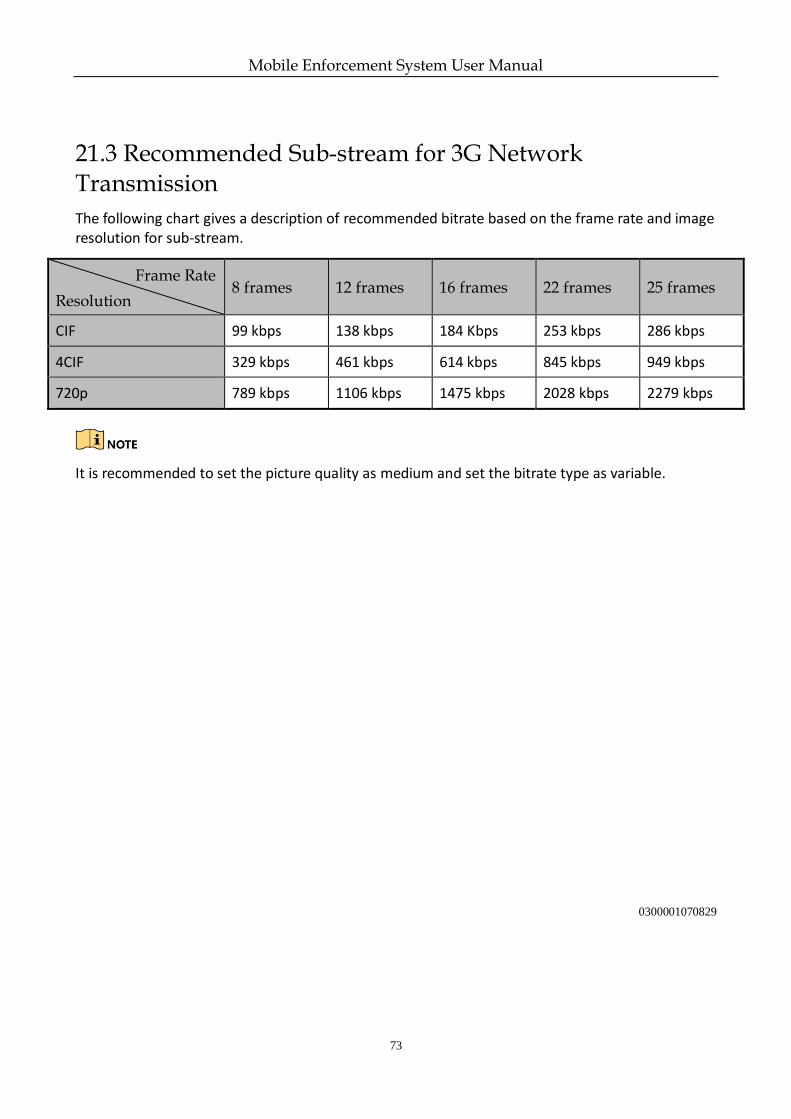
Mobile Enforcement System User Manual
73
21.3 Recommended Sub-stream for 3G Network Transmission
The following chart gives a description of recommended bitrate based on the frame rate and image resolution for sub-stream.
Frame Rate
Resolution 8 frames 12 frames 16 frames 22 frames 25 frames
CIF 99 kbps 138 kbps 184 Kbps 253 kbps 286 kbps
4CIF 329 kbps 461 kbps 614 kbps 845 kbps 949 kbps
720p 789 kbps 1106 kbps 1475 kbps 2028 kbps 2279 kbps
It is recommended to set the picture quality as medium and set the bitrate type as variable.
0300001070829

Mobile Enforcement System User Manual
74
UD08585B
Related Documents


![Sample Copy. Not For Distribution.vc rks eksrh Hkh lLrs yxrs ga mldh rcLle* ds vkxs] fn;s ty tkrs ga mlds fy, NsM rjUuqe* ds vkxs] ?kaVksa Mck, jgrs g mlds rlOoqj* ds eatj] tls Qwyksa](https://static.cupdf.com/doc/110x72/610efb627faa1b4bb03a3db1/sample-copy-not-for-vc-rks-eksrh-hkh-llrs-yxrs-ga-mldh-rclle-ds-vkxs-fns-ty.jpg)