BEST PRACTICE MANUAL DRYERS Prepared for Bureau of Energy Efficiency, (under Ministry of Power, Government of India) Hall no.4, 2 nd Floor, NBCC Tower, Bhikaji Cama Place, New Delhi – 110066. Indian Renewable Energy Development Agency, Core 4A, East Court, 1 st Floor, India Habitat Centre, Lodhi Road, New Delhi – 110003 . By Devki Energy Consultancy Pvt. Ltd., 405, Ivory Terrace, R.C. Dutt Road, Vadodara – 390007, India. 2006

Welcome message from author
This document is posted to help you gain knowledge. Please leave a comment to let me know what you think about it! Share it to your friends and learn new things together.
Transcript
BEST PRACTICE MANUAL
DRYERS
Prepared for
Bureau of Energy Efficiency, (under Ministry of Power, Government of India) Hall no.4, 2
nd Floor, NBCC Tower,
Bhikaji Cama Place, New Delhi – 110066.
Indian Renewable Energy Development Agency, Core 4A, East Court, 1
st Floor, India Habitat Centre,
Lodhi Road, New Delhi – 110003
.
By
Devki Energy Consultancy Pvt. Ltd., 405, Ivory Terrace, R.C. Dutt Road,
Vadodara – 390007, India.
2006
2
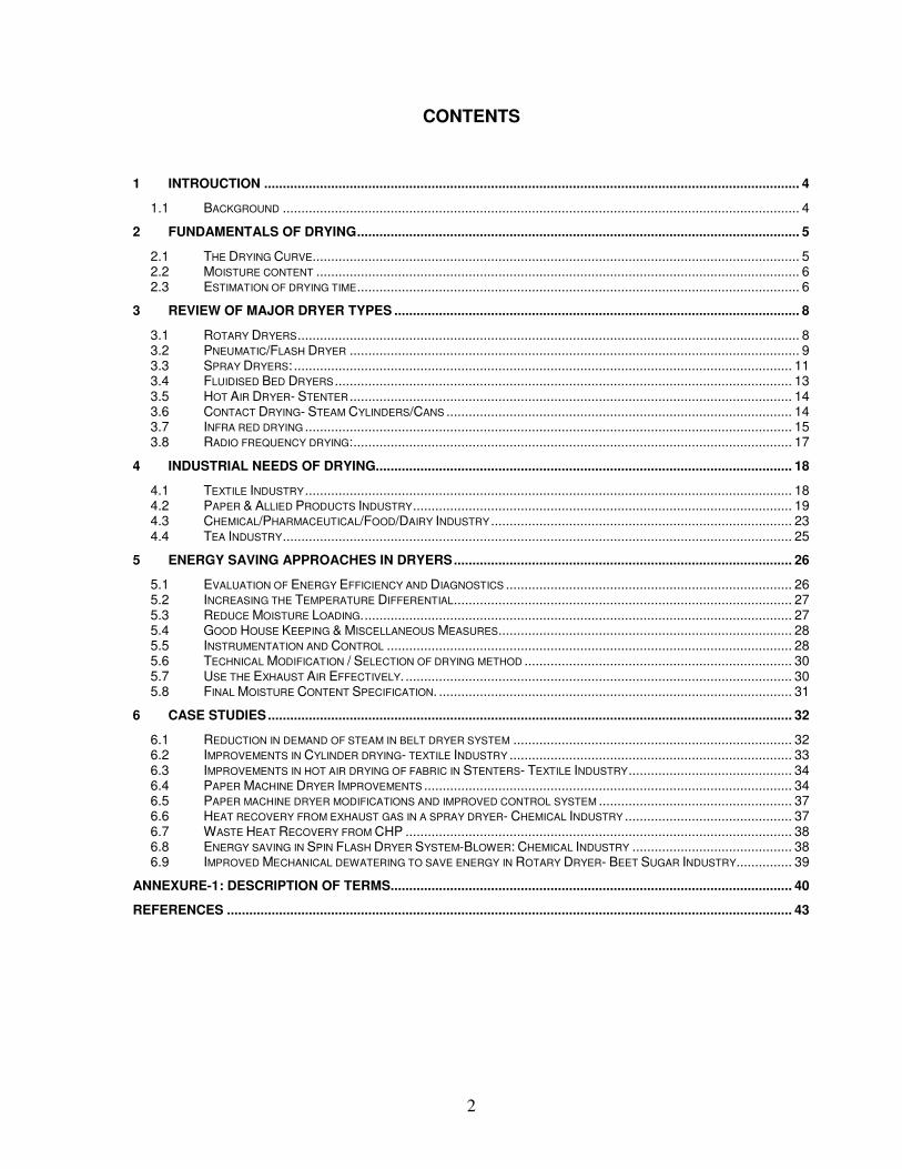
CONTENTS
1 INTROUCTION ................................................................................................................................................ 4
1.1 BACKGROUND ........................................................................................................................................... 4
2 FUNDAMENTALS OF DRYING....................................................................................................................... 5
2.1 THE DRYING CURVE................................................................................................................................... 5 2.2 MOISTURE CONTENT .................................................................................................................................. 6 2.3 ESTIMATION OF DRYING TIME....................................................................................................................... 6
3 REVIEW OF MAJOR DRYER TYPES ............................................................................................................. 8
3.1 ROTARY DRYERS....................................................................................................................................... 8 3.2 PNEUMATIC/FLASH DRYER ......................................................................................................................... 9 3.3 SPRAY DRYERS: ...................................................................................................................................... 11 3.4 FLUIDISED BED DRYERS ........................................................................................................................... 13 3.5 HOT AIR DRYER- STENTER ....................................................................................................................... 14 3.6 CONTACT DRYING- STEAM CYLINDERS/CANS ............................................................................................. 14 3.7 INFRA RED DRYING ................................................................................................................................... 15 3.8 RADIO FREQUENCY DRYING:...................................................................................................................... 17
4 INDUSTRIAL NEEDS OF DRYING................................................................................................................ 18
4.1 TEXTILE INDUSTRY ................................................................................................................................... 18 4.2 PAPER & ALLIED PRODUCTS INDUSTRY...................................................................................................... 19 4.3 CHEMICAL/PHARMACEUTICAL/FOOD/DAIRY INDUSTRY ................................................................................. 23 4.4 TEA INDUSTRY......................................................................................................................................... 25
5 ENERGY SAVING APPROACHES IN DRYERS........................................................................................... 26
5.1 EVALUATION OF ENERGY EFFICIENCY AND DIAGNOSTICS ............................................................................. 26 5.2 INCREASING THE TEMPERATURE DIFFERENTIAL........................................................................................... 27 5.3 REDUCE MOISTURE LOADING.................................................................................................................... 27 5.4 GOOD HOUSE KEEPING & MISCELLANEOUS MEASURES............................................................................... 28 5.5 INSTRUMENTATION AND CONTROL ............................................................................................................. 28 5.6 TECHNICAL MODIFICATION / SELECTION OF DRYING METHOD ........................................................................ 30 5.7 USE THE EXHAUST AIR EFFECTIVELY. ........................................................................................................ 30 5.8 FINAL MOISTURE CONTENT SPECIFICATION. ............................................................................................... 31
6 CASE STUDIES............................................................................................................................................. 32
6.1 REDUCTION IN DEMAND OF STEAM IN BELT DRYER SYSTEM ........................................................................... 32 6.2 IMPROVEMENTS IN CYLINDER DRYING- TEXTILE INDUSTRY ............................................................................ 33 6.3 IMPROVEMENTS IN HOT AIR DRYING OF FABRIC IN STENTERS- TEXTILE INDUSTRY............................................ 34 6.4 PAPER MACHINE DRYER IMPROVEMENTS ................................................................................................... 34 6.5 PAPER MACHINE DRYER MODIFICATIONS AND IMPROVED CONTROL SYSTEM .................................................... 37 6.6 HEAT RECOVERY FROM EXHAUST GAS IN A SPRAY DRYER- CHEMICAL INDUSTRY ............................................. 37 6.7 WASTE HEAT RECOVERY FROM CHP ........................................................................................................ 38 6.8 ENERGY SAVING IN SPIN FLASH DRYER SYSTEM-BLOWER: CHEMICAL INDUSTRY ........................................... 38 6.9 IMPROVED MECHANICAL DEWATERING TO SAVE ENERGY IN ROTARY DRYER- BEET SUGAR INDUSTRY............... 39
ANNEXURE-1: DESCRIPTION OF TERMS............................................................................................................ 40
REFERENCES ........................................................................................................................................................ 43
3
List of Figures Figure 2-1: Drying Curve........................................................................................................................................................... 5
Figure 3-1 Indirect Rotary Dryer............................................................................................................................................... 8
Figure 3-2:Pneumatic /Flash Dryer....................................................................................................................................... 11
Figure 3-3: Spray Dryer........................................................................................................................................................... 12
Figure 3-4: Closed cycle spray dryer lay out ........................................................................................................................ 12
Figure 3-5: Fluidised bed dryer .............................................................................................................................................. 13
Figure 3-6:Schematic of a stenter ........................................................................................................................................... 14
Figure 3-7: Cylinder Dryer....................................................................................................................................................... 15
Figure 3-8: Infrared heating for paper machine ................................................................................................................... 16
Figure 3-9: Cylinder Dryer with radiant burner inside ......................................................................................................... 17
Figure 4-1: Energy flow diagram ............................................................................................................................................ 20
Figure 5-1: Delta T control system for hot air drying ........................................................................................................... 30
Figure 6-1: Heat recovery- Spray Dryer ................................................................................................................................ 38
List of Tables
Table 3-1: Performance data of rotary dryers for various feed materials ................................................................... 9
Table 3-2: Performance data of Pneumatic dryers................................................................................................... 10
Table 4-1: Equilibrium moisture content of textiles................................................................................................... 18
Table 4-2: Steam pressure and drying speed .......................................................................................................... 19
Table 4-3: Theoretical steam requirement in paper drying cylinders........................................................................ 21
Table 5-1: Expected Dryer Efficiencies .................................................................................................................... 26
Table 6-1: Textiel dryer performance ....................................................................................................................... 33
Table 6-2: Energy requirements per tonne of fabric produced................................................................................. 34
4
1 INTROUCTION
1.1 Background
Drying is perhaps the oldest, most common and most diverse of chemical engineering unit operations. Over four hundred types of dryers have been reported in the literature while over one hundred distinct types are commonly available. Energy consumption in drying ranges from a low value of under five percent for the chemical process industries to thirty five percent for the papermaking operations. Drying occurs by effecting vaporization of the liquid by supplying heat to the wet feedstock. Heat may be supplied by convection (direct dryers), by conduction (contact or indirect dryers), radiation or volumetrically by placing the wet material in a microwave or radio frequency electromagnetic field. Over 85 percent of industrial dryers are of the convective type with hot air or direct combustion gases as the drying medium. Over 99 percent of the applications involve removal of water. This is one of the most energy-intensive unit operations due to the high latent heat of vaporization and the inherent inefficiency of using hot air as the (most common) drying medium. This manual describes different types of dryers, their industrial applications and energy conservation opportunities. Although here we will focus only on the dryer, it is very important to note that in practice one must consider a drying system which includes pre-drying stages (e.g., mechanical dewatering, evaporation, pre-conditioning of feed by solids back mixing, dilution or pelletization and feeding) as well as the post-drying stages of exhaust gas cleaning, product collection, partial recirculation of exhausts, cooling of product, coating of product, agglomeration, etc. Energy cost reduction measures are also generally visible in pre and post drying operations and supporting equipments like blowers and pumps as well.
5
2 FUNDAMENTALS OF DRYING
2.1 The Drying Curve
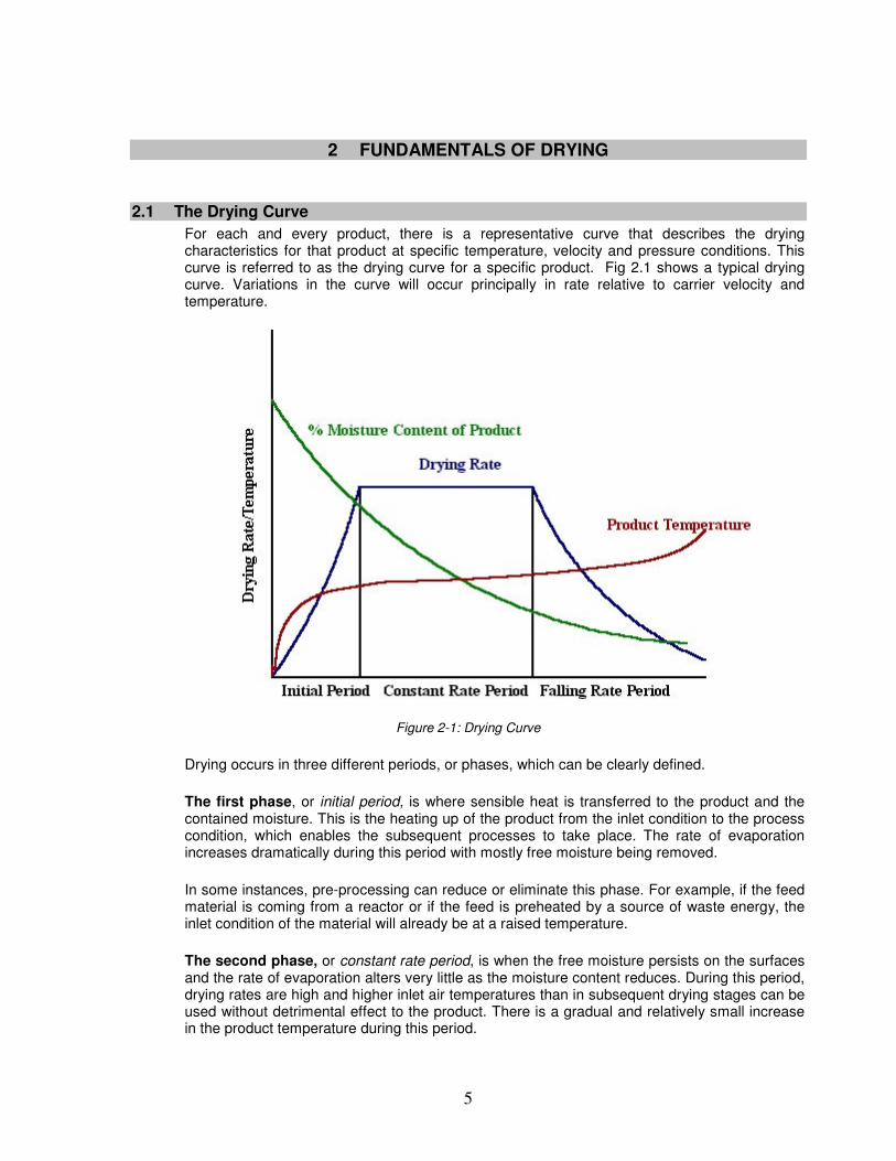
For each and every product, there is a representative curve that describes the drying characteristics for that product at specific temperature, velocity and pressure conditions. This curve is referred to as the drying curve for a specific product. Fig 2.1 shows a typical drying curve. Variations in the curve will occur principally in rate relative to carrier velocity and temperature.
Figure 2-1: Drying Curve
Drying occurs in three different periods, or phases, which can be clearly defined.
The first phase, or initial period, is where sensible heat is transferred to the product and the contained moisture. This is the heating up of the product from the inlet condition to the process condition, which enables the subsequent processes to take place. The rate of evaporation increases dramatically during this period with mostly free moisture being removed.
In some instances, pre-processing can reduce or eliminate this phase. For example, if the feed material is coming from a reactor or if the feed is preheated by a source of waste energy, the inlet condition of the material will already be at a raised temperature.
The second phase, or constant rate period, is when the free moisture persists on the surfaces and the rate of evaporation alters very little as the moisture content reduces. During this period, drying rates are high and higher inlet air temperatures than in subsequent drying stages can be used without detrimental effect to the product. There is a gradual and relatively small increase in the product temperature during this period.
6
Interestingly, a common occurrence is that the time scale of the constant rate period may determine and affect the rate of drying in the next phase.
The third phase, or falling rate period, is the phase during which migration of moisture from the inner interstices of each particle to the outer surface becomes the limiting factor that reduces the drying rate.
2.2 Moisture content
Measuring moisture content allows control of the drying process such that drying is carried out until a specific level of moisture content is achieved rather than for a fixed time period.
Electrical resistance type meters operate on the principle of electrical resistance, which varies minutely in accordance with the moisture content of the item measured. Most of these types of instruments are suitable for measuring moisture content in grain, wood, food, textiles, pulp, paper, chemicals, mortar, soil, coffee, jute, tobacco, rice, copra, and concrete. Resistance meters have an average accuracy of + 1% MC over their operating range.
Dielectric moisture meters rely on surface contact with a flat plate electrode that does not penetrate the wood. Similar to resistance meters, the accuracy of dielectric meters in measuring average MC is + 1% moisture content.
Modern portable moisture balances are available with built in infrared heaters, which directly measures the moisture content of the product and gives a profile of moisture content variations with time. For measuring moisture content in paper rolls or stacks of paper, advanced methods include the use of Radio Frequency Capacitance method. The instrument measures the loss, or change, in RF dielectric constant as affected by the presence of moisture.
Calculation of the quantity of water to be evaporated is explained below with a sample calculation.
If the throughput of the dryer is 60 kg of wet product per hour, drying it from 55% moisture to 10% moisture, the heat requirement is:
60 kg of wet product contains 60 x 0.55 kg water = 33 kg moisture and 60 x (1 - 0.55) = 27 kg bone-dry product. As the final product contains 10% moisture, the moisture in the product is 27/9 = 3 kg and so moisture removed = (33 - 3) = 30 kg Latent heat of evaporation = 2257 kJ kg
-1(at 100 °C
so heat necessary to supply = 30 x 2257 = 6.8
x l04 kJ
2.3 Estimation of drying time
The rate of drying is determined for a sample of substance by suspending it in a cabinet or duct, in a stream of air from a balance. The weight of the drying sample can then be measured as a function of time from wet product to bone dry product. The curve of moisture content as a function of time, similar to fig 2.1, can be plotted. While different solids and different conditions of drying often give rise to curves of very different shapes in the falling rate period, the curve shown above occurs frequently.
During the above measurements, the following conditions are to be followed.

7
1. The sample should be subjected to similar conditions of radiant heat transfer 2. Air should have the same temperature, humidity & velocity
Electronic moisture balances with online data collection/plotting can be used to establish drying curves of materials.
8
3 REVIEW OF MAJOR DRYER TYPES
3.1 Rotary Dryers
Rotary dryers potentially represent the oldest continuous and undoubtedly the most common high volume dryer used in industry, and it has evolved more adaptations of the technology than any other dryer classification.
All rotary dryers have the feed materials passing through a rotating cylinder termed a drum. It is a cylindrical shell usually constructed from steel plates, slightly inclined, typically 0.3-5 m in diameter, 5-90 m in length and rotating at 1-5 rpm. It is operated in some cases with a negative internal pressure (vacuum) to prevent dust escape. Solids introduced at the upper end move towards the lower or discharge end. Depending on the arrangement for the contact between the drying gas and the solids, a dryer may be classified as direct or indirect, con-current or counter-current.
The drum is mounted to large steel rings, termed riding rings, or tires that are supported on fixed trunnion roller assemblies. The rotation is achieved by either a direct drive or chain drive, which require a girth gear or sprocket gear, respectively, on the drum.
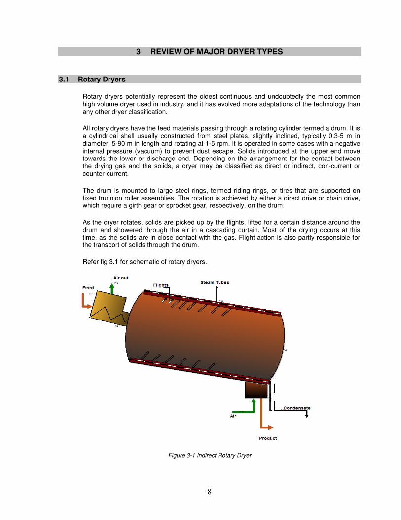
As the dryer rotates, solids are picked up by the flights, lifted for a certain distance around the drum and showered through the air in a cascading curtain. Most of the drying occurs at this time, as the solids are in close contact with the gas. Flight action is also partly responsible for the transport of solids through the drum.
Refer fig 3.1 for schematic of rotary dryers.
Figure 3-1 Indirect Rotary Dryer
9
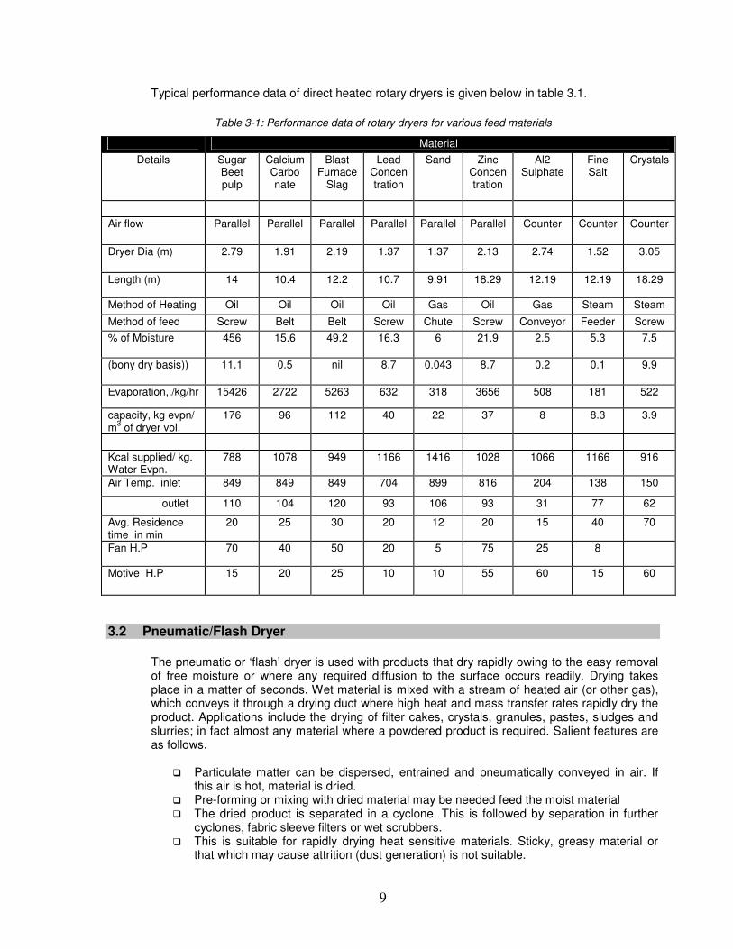
Typical performance data of direct heated rotary dryers is given below in table 3.1.
Table 3-1: Performance data of rotary dryers for various feed materials
Material
Details
Sugar Beet pulp
Calcium Carbo nate
Blast Furnace
Slag
Lead Concen tration
Sand
Zinc Concen tration
Al2 Sulphate
Fine Salt
Crystals
Air flow Parallel Parallel Parallel Parallel Parallel Parallel Counter Counter Counter
Dryer Dia (m) 2.79 1.91 2.19 1.37 1.37 2.13 2.74 1.52 3.05
Length (m) 14 10.4 12.2 10.7 9.91 18.29 12.19 12.19 18.29
Method of Heating Oil Oil Oil Oil Gas Oil Gas Steam Steam
Method of feed Screw Belt Belt Screw Chute Screw Conveyor Feeder Screw
% of Moisture 456 15.6 49.2 16.3 6 21.9 2.5 5.3 7.5
(bony dry basis)) 11.1 0.5 nil 8.7 0.043 8.7 0.2 0.1 9.9
Evaporation,./kg/hr 15426 2722 5263 632 318 3656 508 181 522
capacity, kg evpn/ m
3 of dryer vol.
176 96 112 40 22 37 8 8.3 3.9
Kcal supplied/ kg. Water Evpn.
788 1078 949 1166 1416 1028 1066 1166 916
Air Temp. inlet 849 849 849 704 899 816 204 138 150
outlet 110 104 120 93 106 93 31 77 62
Avg. Residence time in min
20 25 30 20 12 20 15 40 70
Fan H.P 70 40 50 20 5 75 25 8
Motive H.P 15 20 25 10 10 55 60 15 60
3.2 Pneumatic/Flash Dryer
The pneumatic or ‘flash’ dryer is used with products that dry rapidly owing to the easy removal of free moisture or where any required diffusion to the surface occurs readily. Drying takes place in a matter of seconds. Wet material is mixed with a stream of heated air (or other gas), which conveys it through a drying duct where high heat and mass transfer rates rapidly dry the product. Applications include the drying of filter cakes, crystals, granules, pastes, sludges and slurries; in fact almost any material where a powdered product is required. Salient features are as follows.
� Particulate matter can be dispersed, entrained and pneumatically conveyed in air. If this air is hot, material is dried.
� Pre-forming or mixing with dried material may be needed feed the moist material � The dried product is separated in a cyclone. This is followed by separation in further
cyclones, fabric sleeve filters or wet scrubbers. � This is suitable for rapidly drying heat sensitive materials. Sticky, greasy material or
that which may cause attrition (dust generation) is not suitable.
10
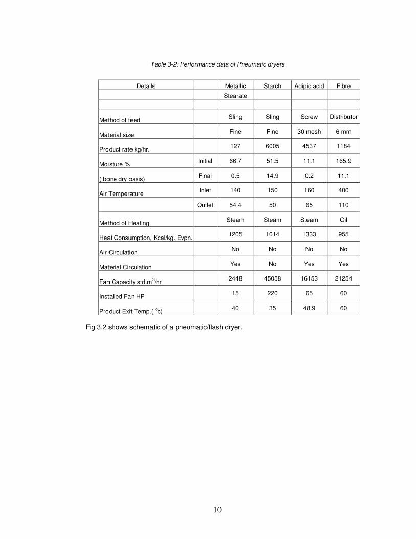
Table 3-2: Performance data of Pneumatic dryers
Details Metallic Starch Adipic acid Fibre
Stearate
Method of feed Sling Sling Screw Distributor
Material size Fine Fine 30 mesh 6 mm
Product rate kg/hr. 127 6005 4537 1184
Moisture % Initial 66.7 51.5 11.1 165.9
( bone dry basis) Final 0.5 14.9 0.2 11.1
Air Temperature Inlet 140 150 160 400
Outlet 54.4 50 65 110
Method of Heating Steam Steam Steam Oil
Heat Consumption, Kcal/kg. Evpn. 1205 1014 1333 955
Air Circulation No No No No
Material Circulation Yes No Yes Yes
Fan Capacity std.m3/hr
2448 45058 16153 21254
Installed Fan HP 15 220 65 60
Product Exit Temp.( oc)
40 35 48.9 60
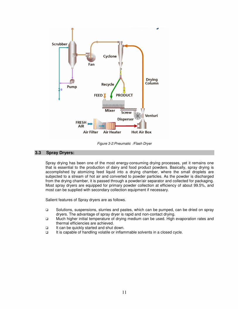
Fig 3.2 shows schematic of a pneumatic/flash dryer.
11
Figure 3-2:Pneumatic /Flash Dryer
3.3 Spray Dryers:
Spray drying has been one of the most energy-consuming drying processes, yet it remains one that is essential to the production of dairy and food product powders. Basically, spray drying is accomplished by atomizing feed liquid into a drying chamber, where the small droplets are subjected to a stream of hot air and converted to powder particles. As the powder is discharged from the drying chamber, it is passed through a powder/air separator and collected for packaging. Most spray dryers are equipped for primary powder collection at efficiency of about 99.5%, and most can be supplied with secondary collection equipment if necessary.
Salient features of Spray dryers are as follows.
� Solutions, suspensions, slurries and pastes, which can be pumped, can be dried on spray dryers. The advantage of spray dryer is rapid and non-contact drying.
� Much higher initial temperature of drying medium can be used. High evaporation rates and thermal efficiencies are achieved.
� It can be quickly started and shut down. � It is capable of handling volatile or inflammable solvents in a closed cycle.
12
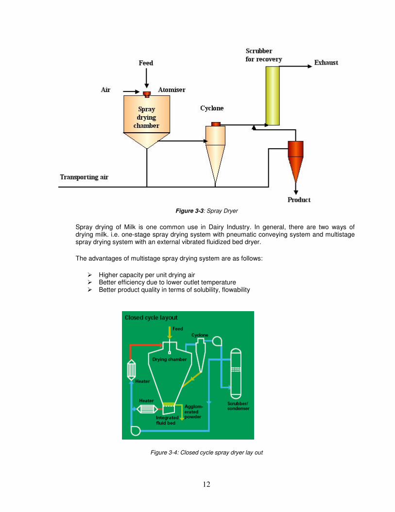
Figure 3-3: Spray Dryer
Spray drying of Milk is one common use in Dairy Industry. In general, there are two ways of drying milk. i.e. one-stage spray drying system with pneumatic conveying system and multistage spray drying system with an external vibrated fluidized bed dryer.
The advantages of multistage spray drying system are as follows:
� Higher capacity per unit drying air � Better efficiency due to lower outlet temperature � Better product quality in terms of solubility, flowability
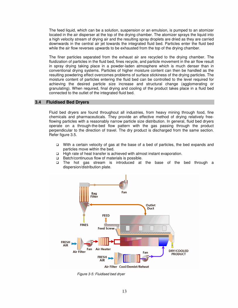
Figure 3-4: Closed cycle spray dryer lay out
13
The feed liquid, which can be a solution, suspension or an emulsion, is pumped to an atomizer located in the air disperser at the top of the drying chamber. The atomizer sprays the liquid into a high velocity stream of drying air and the resulting spray droplets are dried as they are carried downwards in the central air jet towards the integrated fluid bed. Particles enter the fluid bed while the air flow reverses upwards to be exhausted from the top of the drying chamber. The finer particles separated from the exhaust air are recycled to the drying chamber. The fluidization of particles in the fluid bed, fines recycle, and particle movement in the air flow result in spray drying taking place in a powder-laden atmosphere which is much denser than in conventional drying systems. Particles of higher moisture content can then be handled as the resulting powdering effect overcomes problems of surface stickiness of the drying particles. The moisture content of particles entering the fluid bed can be controlled to the level required for achieving the desired particle size increase and structural change (agglomerating or granulating). When required, final drying and cooling of the product takes place in a fluid bed connected to the outlet of the integrated fluid bed.
3.4 Fluidised Bed Dryers
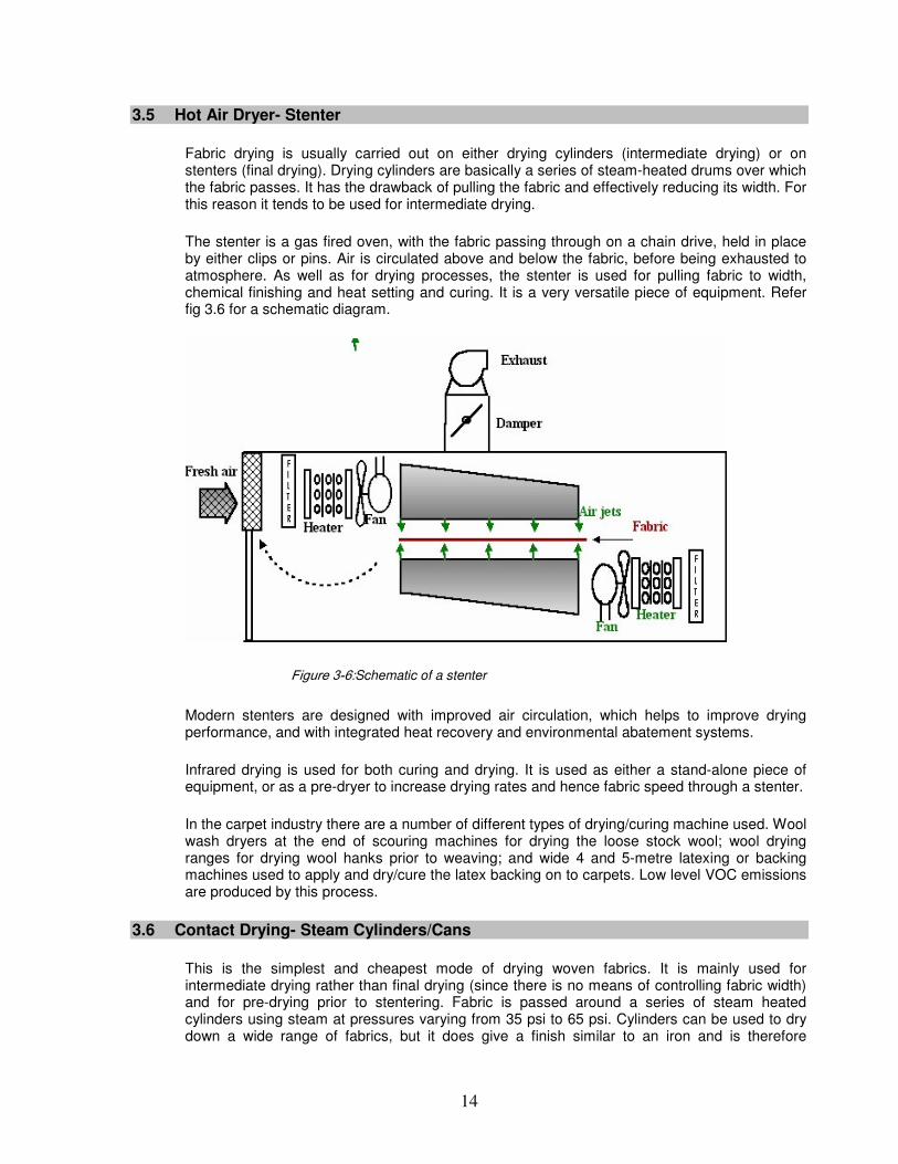
Fluid bed dryers are found throughout all industries, from heavy mining through food, fine chemicals and pharmaceuticals. They provide an effective method of drying relatively free-flowing particles with a reasonably narrow particle size distribution. In general, fluid bed dryers operate on a through-the-bed flow pattern with the gas passing through the product perpendicular to the direction of travel. The dry product is discharged from the same section. Refer figure 3.5.
� With a certain velocity of gas at the base of a bed of particles, the bed expands and particles move within the bed.
� High rate of heat transfer is achieved with almost instant evaporation. � Batch/continuous flow of materials is possible. � The hot gas stream is introduced at the base of the bed through a
dispersion/distribution plate.
Figure 3-5: Fluidised bed dryer
14
3.5 Hot Air Dryer- Stenter
Fabric drying is usually carried out on either drying cylinders (intermediate drying) or on stenters (final drying). Drying cylinders are basically a series of steam-heated drums over which the fabric passes. It has the drawback of pulling the fabric and effectively reducing its width. For this reason it tends to be used for intermediate drying.
The stenter is a gas fired oven, with the fabric passing through on a chain drive, held in place by either clips or pins. Air is circulated above and below the fabric, before being exhausted to atmosphere. As well as for drying processes, the stenter is used for pulling fabric to width, chemical finishing and heat setting and curing. It is a very versatile piece of equipment. Refer fig 3.6 for a schematic diagram.
Figure 3-6:Schematic of a stenter
Modern stenters are designed with improved air circulation, which helps to improve drying performance, and with integrated heat recovery and environmental abatement systems.
Infrared drying is used for both curing and drying. It is used as either a stand-alone piece of equipment, or as a pre-dryer to increase drying rates and hence fabric speed through a stenter.
In the carpet industry there are a number of different types of drying/curing machine used. Wool wash dryers at the end of scouring machines for drying the loose stock wool; wool drying ranges for drying wool hanks prior to weaving; and wide 4 and 5-metre latexing or backing machines used to apply and dry/cure the latex backing on to carpets. Low level VOC emissions are produced by this process.
3.6 Contact Drying- Steam Cylinders/Cans
This is the simplest and cheapest mode of drying woven fabrics. It is mainly used for intermediate drying rather than final drying (since there is no means of controlling fabric width) and for pre-drying prior to stentering. Fabric is passed around a series of steam heated cylinders using steam at pressures varying from 35 psi to 65 psi. Cylinders can be used to dry down a wide range of fabrics, but it does give a finish similar to an iron and is therefore
15
unsuitable where a surface effect is present or required. In stenters, the fabric is width wise stretched for width fixation by a series of holding clips or pins mounted on a pair of endless chains.
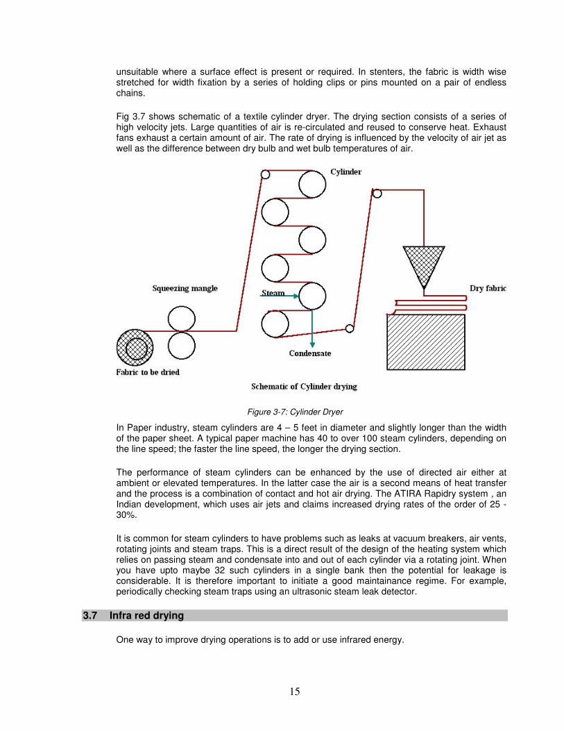
Fig 3.7 shows schematic of a textile cylinder dryer. The drying section consists of a series of high velocity jets. Large quantities of air is re-circulated and reused to conserve heat. Exhaust fans exhaust a certain amount of air. The rate of drying is influenced by the velocity of air jet as well as the difference between dry bulb and wet bulb temperatures of air.
Figure 3-7: Cylinder Dryer
In Paper industry, steam cylinders are 4 – 5 feet in diameter and slightly longer than the width of the paper sheet. A typical paper machine has 40 to over 100 steam cylinders, depending on the line speed; the faster the line speed, the longer the drying section.
The performance of steam cylinders can be enhanced by the use of directed air either at ambient or elevated temperatures. In the latter case the air is a second means of heat transfer and the process is a combination of contact and hot air drying. The ATIRA Rapidry system , an Indian development, which uses air jets and claims increased drying rates of the order of 25 - 30%.
It is common for steam cylinders to have problems such as leaks at vacuum breakers, air vents, rotating joints and steam traps. This is a direct result of the design of the heating system which relies on passing steam and condensate into and out of each cylinder via a rotating joint. When you have upto maybe 32 such cylinders in a single bank then the potential for leakage is considerable. It is therefore important to initiate a good maintainance regime. For example, periodically checking steam traps using an ultrasonic steam leak detector.
3.7 Infra red drying
One way to improve drying operations is to add or use infrared energy.
16
Infrared energy can be generated by electric or gas infrared heaters or emitters. Each energy source has advantages and disadvantages. Typically, gas infrared systems are more expensive to buy because they require safety controls and gas-handling equipment, but they often are less expensive to run because gas usually is cheaper than electricity. Gas infrared is often a good choice for applications that require a lot of energy. Products such as nonwoven and textile webs are examples where gas often is a good choice.
Gas IR heaters produce an infrared wavelength that is readily absorbed by the water in the sheet. This leads to a higher temperature and a drying efficiency increase that cannot be duplicated by conduction and convection temperatures alone.
Table 3-3: Drying rates for dryers
Method Type of Drying Drying Rate
(lbs water/hr/ft2)
Steam Cans Conduction 2 - 6
Air Hoods Impingement Convection 4 - 8
Gas IR Radiation + Convection 30+
By contrast, electric infrared is likely better for sensitive substrates such as film and certain fabrics, where extreme control and uniformity is required. Electric infrared heaters can be divided into multiple, separately controlled temperature zones with tolerances as tight as +/-1
oF.
Both electric and gas infrared typically are controlled by thermocouple feedback control loops that regulate the electrical power or fuel mixture going to the infrared heaters. For more precise control, temperature feedback from the product using an optical pyrometer is used.
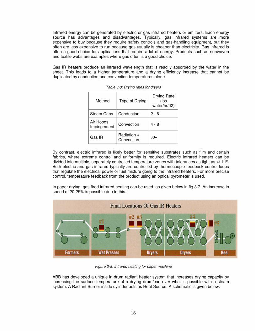
In paper drying, gas fired infrared heating can be used, as given below in fig 3.7. An increase in speed of 20-25% is possible due to this.
Figure 3-8: Infrared heating for paper machine
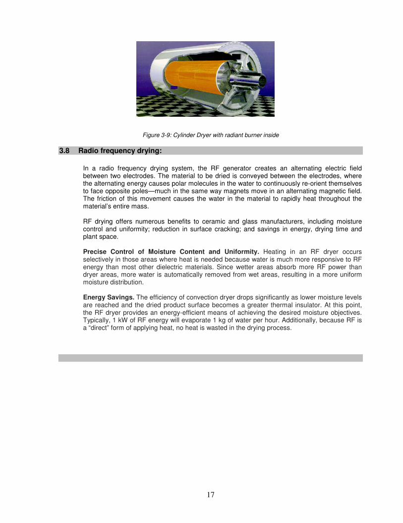
ABB has developed a unique in-drum radiant heater system that increases drying capacity by increasing the surface temperature of a drying drum/can over what is possible with a steam system. A Radiant Burner inside cylinder acts as Heat Source. A schematic is given below.
17
Figure 3-9: Cylinder Dryer with radiant burner inside
3.8 Radio frequency drying:
In a radio frequency drying system, the RF generator creates an alternating electric field between two electrodes. The material to be dried is conveyed between the electrodes, where the alternating energy causes polar molecules in the water to continuously re-orient themselves to face opposite poles—much in the same way magnets move in an alternating magnetic field. The friction of this movement causes the water in the material to rapidly heat throughout the material’s entire mass. RF drying offers numerous benefits to ceramic and glass manufacturers, including moisture control and uniformity; reduction in surface cracking; and savings in energy, drying time and plant space. Precise Control of Moisture Content and Uniformity. Heating in an RF dryer occurs selectively in those areas where heat is needed because water is much more responsive to RF energy than most other dielectric materials. Since wetter areas absorb more RF power than dryer areas, more water is automatically removed from wet areas, resulting in a more uniform moisture distribution. Energy Savings. The efficiency of convection dryer drops significantly as lower moisture levels are reached and the dried product surface becomes a greater thermal insulator. At this point, the RF dryer provides an energy-efficient means of achieving the desired moisture objectives. Typically, 1 kW of RF energy will evaporate 1 kg of water per hour. Additionally, because RF is a “direct” form of applying heat, no heat is wasted in the drying process.
18
4 INDUSTRIAL NEEDS OF DRYING
4.1 Textile Industry
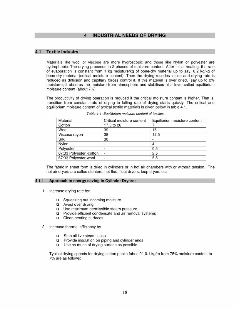
Materials like wool or viscose are more hygroscopic and those like Nylon or polyester are hydrophobic. The drying proceeds in 2 phases of moisture content. After initial heating, the rate of evaporation is constant from 1 kg moisture/kg of bone-dry material up to say, 0.2 kg/kg of bone-dry material (critical moisture content). Then the drying recedes inside and drying rate is reduced as diffusion and capillary forces control it. If this material is over dried, (say up to 2% moisture), it absorbs the moisture from atmosphere and stabilises at a level called equilibrium moisture content (about 7%). The productivity of drying operation is reduced if the critical moisture content is higher. That is, transition from constant rate of drying to falling rate of drying starts quickly. The critical and equilibrium moisture content of typical textile materials is given below in table 4.1.
Table 4-1: Equilibrium moisture content of textiles
Material Critical moisture content Equilibrium moisture content Cotton 17.5 to 26 7 Wool 39 16 Viscose rayon 38 12.5 Silk 30 - Nylon - 4 Polyester - 0.5 67:33 Polyester -cotton - 2.5 67:33 Polyester-wool - 5.5
The fabric in sheet form is dried in cylinders or in hot air chambers with or without tension. The hot air dryers are called stenters, hot flue, float dryers, loop dryers etc
4.1.1 Approach to energy saving in Cylinder Dryers:
1. Increase drying rate by:
� Squeezing out incoming moisture � Avoid over drying � Use maximum permissible steam pressure � Provide efficient condensate and air removal systems � Clean heating surfaces
2. Increase thermal efficiency by
� Stop all live steam leaks � Provide insulation on piping and cylinder ends � Use as much of drying surface as possible
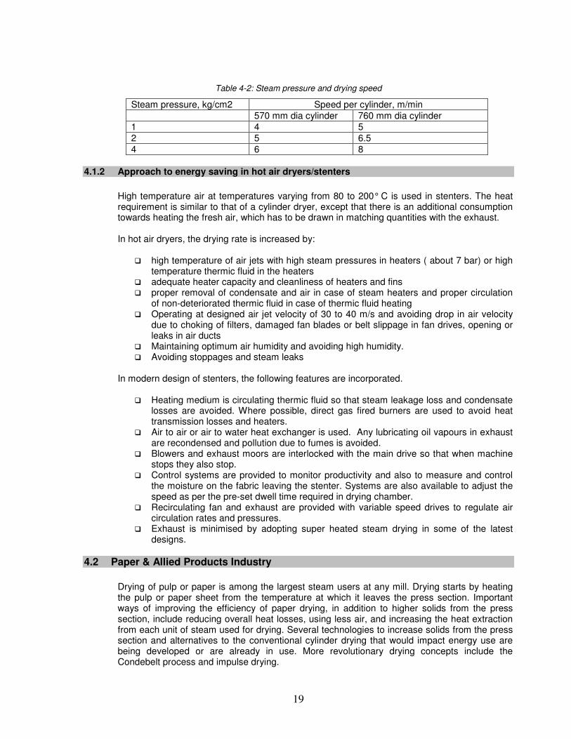
Typical drying speeds for drying cotton poplin fabric 0f 0.1 kg/m from 75% moisture content to 7% are as follows:
19
Table 4-2: Steam pressure and drying speed
Steam pressure, kg/cm2 Speed per cylinder, m/min 570 mm dia cylinder 760 mm dia cylinder 1 4 5 2 5 6.5 4 6 8
4.1.2 Approach to energy saving in hot air dryers/stenters
High temperature air at temperatures varying from 80 to 200° C is used in stenters. The heat requirement is similar to that of a cylinder dryer, except that there is an additional consumption towards heating the fresh air, which has to be drawn in matching quantities with the exhaust. In hot air dryers, the drying rate is increased by:
� high temperature of air jets with high steam pressures in heaters ( about 7 bar) or high temperature thermic fluid in the heaters
� adequate heater capacity and cleanliness of heaters and fins � proper removal of condensate and air in case of steam heaters and proper circulation
of non-deteriorated thermic fluid in case of thermic fluid heating � Operating at designed air jet velocity of 30 to 40 m/s and avoiding drop in air velocity
due to choking of filters, damaged fan blades or belt slippage in fan drives, opening or leaks in air ducts
� Maintaining optimum air humidity and avoiding high humidity. � Avoiding stoppages and steam leaks
In modern design of stenters, the following features are incorporated.
� Heating medium is circulating thermic fluid so that steam leakage loss and condensate losses are avoided. Where possible, direct gas fired burners are used to avoid heat transmission losses and heaters.
� Air to air or air to water heat exchanger is used. Any lubricating oil vapours in exhaust are recondensed and pollution due to fumes is avoided.
� Blowers and exhaust moors are interlocked with the main drive so that when machine stops they also stop.
� Control systems are provided to monitor productivity and also to measure and control the moisture on the fabric leaving the stenter. Systems are also available to adjust the speed as per the pre-set dwell time required in drying chamber.
� Recirculating fan and exhaust are provided with variable speed drives to regulate air circulation rates and pressures.
� Exhaust is minimised by adopting super heated steam drying in some of the latest designs.
4.2 Paper & Allied Products Industry
Drying of pulp or paper is among the largest steam users at any mill. Drying starts by heating the pulp or paper sheet from the temperature at which it leaves the press section. Important ways of improving the efficiency of paper drying, in addition to higher solids from the press section, include reducing overall heat losses, using less air, and increasing the heat extraction from each unit of steam used for drying. Several technologies to increase solids from the press section and alternatives to the conventional cylinder drying that would impact energy use are being developed or are already in use. More revolutionary drying concepts include the Condebelt process and impulse drying.
20
Bulk of the paper in sheet form is dried in Cylinder/Can dryers. Paper pulp takes many shapes as molded materials, boards, light and heavy weight paper, and resin impregnated/coated paper as laminates/wall papers. While molded articles are dried in truck tray tunnels or continuous conveyor sheet dryers, special coated paper is handled in continuous festoon dryers.
4.2.1 Paper Making Process
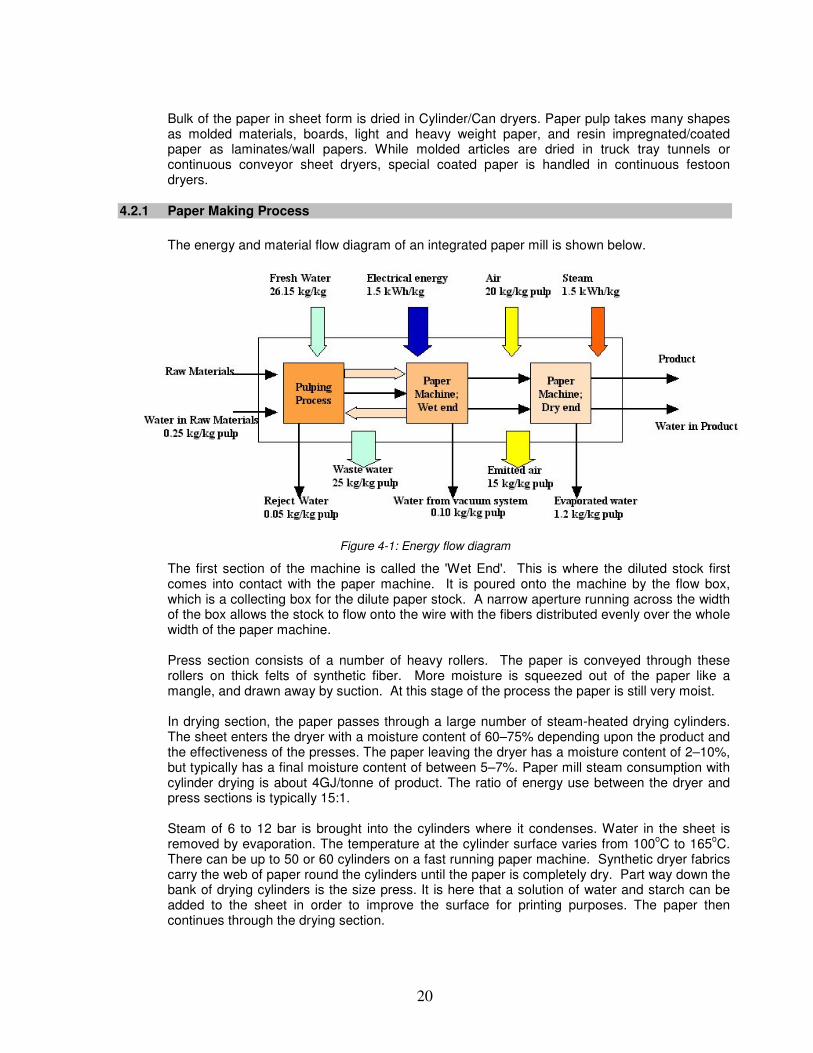
The energy and material flow diagram of an integrated paper mill is shown below.
Figure 4-1: Energy flow diagram
The first section of the machine is called the 'Wet End'. This is where the diluted stock first comes into contact with the paper machine. It is poured onto the machine by the flow box, which is a collecting box for the dilute paper stock. A narrow aperture running across the width of the box allows the stock to flow onto the wire with the fibers distributed evenly over the whole width of the paper machine. Press section consists of a number of heavy rollers. The paper is conveyed through these rollers on thick felts of synthetic fiber. More moisture is squeezed out of the paper like a mangle, and drawn away by suction. At this stage of the process the paper is still very moist. In drying section, the paper passes through a large number of steam-heated drying cylinders. The sheet enters the dryer with a moisture content of 60–75% depending upon the product and the effectiveness of the presses. The paper leaving the dryer has a moisture content of 2–10%, but typically has a final moisture content of between 5–7%. Paper mill steam consumption with cylinder drying is about 4GJ/tonne of product. The ratio of energy use between the dryer and press sections is typically 15:1. Steam of 6 to 12 bar is brought into the cylinders where it condenses. Water in the sheet is removed by evaporation. The temperature at the cylinder surface varies from 100
oC to 165
oC.
There can be up to 50 or 60 cylinders on a fast running paper machine. Synthetic dryer fabrics carry the web of paper round the cylinders until the paper is completely dry. Part way down the bank of drying cylinders is the size press. It is here that a solution of water and starch can be added to the sheet in order to improve the surface for printing purposes. The paper then continues through the drying section.
21
The calendar consists of a stack of polished iron rollers mounted one above the other. The calendar 'irons' the paper. The surface of the paper is smoothed and polished. The paper now comes off the machine ready for reeling up into large reels, each of which may contain up to 20 tonnes of paper. These large reels are either cut into sheets or slit into smaller reels according to the customer's requirements.
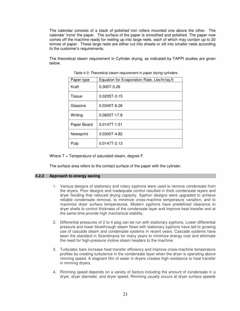
The theoretical steam requirement in Cylinder drying, as indicated by TAPPI studies are given below.
Table 4-3: Theoretical steam requirement in paper drying cylinders
Paper type Equation for Evaporation Rate, Lbs/hr/sq.ft
Kraft 0.300T-5.26
Tissue 0.0205T-3.15
Glassine 0.0340T-6.26
Writing 0.0820T-17.8
Paper Board 0.0147T-1.51
Newsprint 0.0300T-4.82
Pulp 0.0147T-2.13
Where T = Temperature of saturated steam, degree F.
The surface area refers to the contact surface of the paper with the cylinder.
4.2.2 Approach to energy saving
1. Various designs of stationary and rotary syphons were used to remove condensate from
the dryers. Poor designs and inadequate control resulted in thick condensate layers and dryer flooding that reduced drying capacity. Syphon designs were upgraded to achieve reliable condensate removal, to minimize cross-machine temperature variation, and to maximize dryer surface temperatures. Modern syphons have predefined clearance to dryer shells to control thickness of the condensate layer and improve heat transfer and at the same time provide high mechanical stability.
2. Differential pressures of 2 to 4 psig can be run with stationary syphons. Lower differential
pressure and lower blowthrough steam flows with stationary syphons have led to growing use of cascade steam and condensate systems in recent years. Cascade systems have been the standard in Scandinavia for many years to minimize energy cost and eliminate the need for high-pressure motive steam headers to the machine.
3. Turbulator bars increase heat transfer efficiency and improve cross-machine temperature
profiles by creating turbulence in the condensate layer when the dryer is operating above rimming speed. A stagnant film of water in dryers creates high resistance to heat transfer in rimming dryers.
4. Rimming speed depends on a variety of factors including the amount of condensate in a
dryer, dryer diameter, and dryer speed. Rimming usually occurs at dryer surface speeds
22
over 900 fpm. Manufacturers recommend the installation of Turbulator bars on drying-limited paper machines operating at speeds as low as 900 fpm and machines with poor CD moisture profiles.
5. Bar design and configuration can have a significant impact on performance. Syphon
clearance is also closely related to the optimal performance of dryer bars. With the correct condensate depth, the condensate resonates "in tune" with dryer rotation. This greatly increases the rate of heat transfer from the dryer cylinder.
6. For some applications, improvement in uniformity of heat transfer is needed without any
increase in the rate of heat transfer. "De-tuned" Turbulator bars were developed for such applications. These have been installed on some newsprint machines to reduce heat transfer efficiency while maintaining uniform CD profiles. Many newsprint machines have excess drying capacity and must operate at very low dryer steam pressures, due to improved press section water removal and lower basis weights. "De-tuned" bars permit running higher steam pressures with improved steam and condensate system control.
When the paper sheet enters the paper machine Dryer Section, it is about 50% water. It must be dried to less than 10% water for a finished product. The drying section of the process consumes around 90% of the steam demand of a typical paper mill. Less energy is used in removing water from the web by mechanical means than by evaporation. Monitor product dryness leaving the press section; a 1% increase in dryness leaving the press results in a 4% decrease in steam consumption of the drying section. There is a balance between removing water at the wet end and in presses through increased electrical power for presses and vacuum against the value of the lower cost steam saved. Dewatering in the papermaking machine is achieved by increasing the nip pressure and by applying it uniformly in the cross direction.
� Examine compliance of final product dryness and overall evenness of quality. Poor moisture profile is usually corrected by over drying
� Cylinder wall finish and cleanliness and close contact between the feedstock and the
cylinder external surface will affect drying rates.
� Characteristics of both the paper and the type of felt used will affect operational efficiencies.
� Make sure that water can be efficiently drained away from the forming section in the
most effective manner. Check collection points, weirs, pipe-work and sumps for downstream blockages.
� Ensure proper maintenance of the vacuum system removing water through the suction
boxes. Check seals for condition and leakage. Power is wasted if too high a vacuum is maintained, so ensure adequate levels are maintained and that controls are operable and accurate. For overall drying operations. Develop a figure for energy input per kg water evaporated, (theoretical minimum is 0.63 kWh/kg water).
� Examine suitability and efficacy of drying mechanism controls. Check whether the end
point temperature and humidity controls installed and working correctly. Less energy is used in removing water from the web by mechanical means than by evaporation; check on moisture levels at the interface.
� Examine compliance of final product dryness and overall evenness of quality. Poor
moisture profile is usually corrected by over drying.
23
� Monitor dryer inlet and outlet air temperatures and flows over daily/weekly operations. Link to product throughput and moisture levels to establish a heat and mass balance for overall drying operations. Develop a figure for energy input per kg water evaporated, (theoretical minimum is 0.63 kWh/kg water).
� Ensure adequate removal of condensate and uncondensed gases from within drying
cylinders. Uneven distribution of the steam supply over the internal surface could affect paper condition.
The concepts for saving energy in cylinder dryers for textiles discussed in previous section apply to paper drying as well.
4.2.3 New Technologies for efficient drying
Impulse drying is a technology that improves the mechanical dehydration of paper and consequently reduces the amount of water that has to be removed in the drying section. The press cylinder is heated by steam or electro-techniques (infrared, induction heating). Very high temperatures (200-500
oC) are used and contact time is very short.
In the Condebelt drying concept a wet web (sheet of paper) is carried between two steel bands, one hot band and one cold band, and subjected to high pressure (max. 10 bar) and temperature (max. 180
oC). Heat is transferred from the hot band to the sheet; moisture
evaporates and traverses through two wire screens to the cold band, where it condenses. The condensate is carried away by the thickest of the two wire screens. The sheet is dried in absence of air. In contrast with conventional pressing technologies and impulse drying the pressure is maintained for several seconds, resulting in good paper qualities. Drying rates are 5-15 times as high as in conventional drying. Condensing belt drying can dry paper from 44% (exit conventional pressing section) to 94%. The technical life of paper machines is approximately 20 years and investment costs are extremely high. Demonstration of new pressing and drying technologies will be difficult. The first Condebelt dryer is delivered to Finnish paper mill (Pankakoski) and would start production in the 1996. Condensing belt will be available for all types of paper, except tissue.
4.3 Chemical/Pharmaceutical/Food/Dairy Industry
In Chemical Industry, Inorganic salts and insoluble organic dyes require drying. Many of the materials are heat resistive and require time temperature control to prevent degradation and exact get exact shades. These require tray/vacuum dryers in batch process and semi continuous truck and tray tunnel dryers, direct and indirect rotary dryers, continuous through circulation dryers and spray dryers for large productions. In Pharmaceutical industry, the material in powder, granular or crystalline form having moisture/solvents needs drying. These are generally heat sensitive. These require all kinds of tray dryers, fluidised bed dryers and vibratory conveyor dryers for small productions and rotary dryers, flash dryers, Continuous through circulation and fluidised bed for large production. Very sensitive materials have to be dried in Spray dryers, High vacuum tray dryers and freeze dryers.
Dryers for liquids
Simple and colloidal solutions, emulsions such as salt solutions, extracts, milk, blood, waste liquors, rubber latex etc. are examples. For large production, spray dryers of direct contact and continuous operation can be used. It permits use of high temperatures with heat sensitive materials. The product usually is powdery, free flowing, spherical and has low bulk density.
24
Another method for continuous drying is Film drum dryers at atmospheric pressure and vacuum. The product is usually flaky and dusty and maintenance costs may be high. For small batches, jacketed pan types dryers are used. These can be cleaned and amenable to solvent recovery. For heat sensitive and readily oxidised pharmaceutical materials like Penicillin and blood, freeze dryers are useful.
Dryers for Slurries:
Pumpable suspensions such as pigment slurries, soap and detergents, calcium carbonate, bentonite, clay slip lead concentrates etc. are examples of slurries require drying in chemical industries. Spray dryers could be used with pressure nozzle atomisers. Film dryers with twin are widely used. For small batches, vacuum shelf dryers can be used. Tray/compartment dryers are used for very small –laboratory type production.
Dryers for pastes and sludges
Filter press cakes, sedimentation sludges, centrifuged solids, starch etc. require drying in chemical/food industry. Continuous Tray tunnels are suitable for small and large productions. For small batches, tray-compartment dryer is used. These have very long drying times and for larger production, investment and operating costs are high. If the material can be preformed, then batch type or continuous through circulation is possible. For heat sensitive, readily oxidisable material, indirectly heated vacuum shelf dryer can be used. Spray dryers would need very special pumping equipment to feed the atomiser.
Dryers for free flowing powders
100 mesh or less free flowing when wet but dusty when dry such as cement, clay, pigments, precipitates etc. are examples. Screw conveyors and indirectly heated rotary dryers suit a large range of materials and capabilities and have continuous dust free operation. Drying with steam is possible. Rotary vacuum dryers are considered for large batches of heat sensitive material where solvent recovery is also desired. For large capacities, pneumatic conveying type direct contact dryers are suitable if the material can be suspended and looses moisture easily. If dusting is not too severe, direct rotary dryers of continuous type can suit many materials. Fluidised bed batch type dryers can be used in case of non-dusty materials.
Dryers for granular/Crystalline or fibrous materials
Larger than 100 mesh such as sand ores, salt crystals, rayon staples, potato strips, synthetic rubber etc. are the typical materials. For most materials and capacities, continuous rotary dryers are suitable. The limitation comes only in the form of dust and abrasion. For large batches of heat sensitive materials, or where solvent is to be recovered, batch type indirect vacuum rotary dryers can be used. Product is subjected to some grinding action and dust collection may be required. Screw conveyor and indirect rotary dryer with continuous operation have low dust loss. Continuous pneumatic conveying direct type dryers have high capacities and can handle materials that are easily suspended. Fluidised bed dryers are suitable for crystals, granules and short fibers. Tray/vacuum tray dryers may be selected for small batches, keeping in mind that drying times are long. Where primarily surface moisture only is to be removed, infra red dryers can be considered. Approach to energy saving:
� Heat recovery from exhaust air to preheat incoming air � Proper mechanical dewatering of feed before entering the dryer � Online instrumentation and automatic feed forward controls � Energy saving by optimising auxiliary equipment operation.
25
4.4 Tea Industry
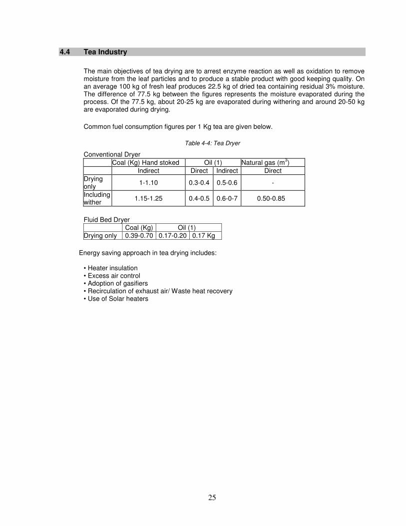
The main objectives of tea drying are to arrest enzyme reaction as well as oxidation to remove moisture from the leaf particles and to produce a stable product with good keeping quality. On an average 100 kg of fresh leaf produces 22.5 kg of dried tea containing residual 3% moisture. The difference of 77.5 kg between the figures represents the moisture evaporated during the process. Of the 77.5 kg, about 20-25 kg are evaporated during withering and around 20-50 kg are evaporated during drying.
Common fuel consumption figures per 1 Kg tea are given below.
Table 4-4: Tea Dryer
Conventional Dryer Coal (Kg) Hand stoked Oil (1) Natural gas (m
3)
Indirect Direct Indirect Direct Drying only
1-1.10 0.3-0.4 0.5-0.6 -
Including wither
1.15-1.25 0.4-0.5 0.6-0-7 0.50-0.85
Fluid Bed Dryer Coal (Kg) Oil (1) Drying only 0.39-0.70 0.17-0.20 0.17 Kg
Energy saving approach in tea drying includes:
• Heater insulation • Excess air control • Adoption of gasifiers • Recirculation of exhaust air/ Waste heat recovery • Use of Solar heaters
26
5 ENERGY SAVING APPROACHES IN DRYERS
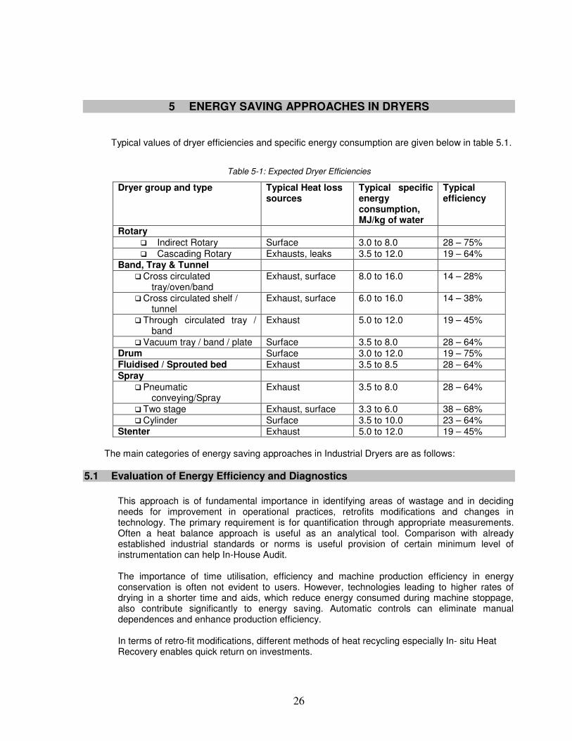
Typical values of dryer efficiencies and specific energy consumption are given below in table 5.1.
Table 5-1: Expected Dryer Efficiencies
Dryer group and type Typical Heat loss sources
Typical specific energy consumption, MJ/kg of water
Typical efficiency
Rotary � Indirect Rotary Surface 3.0 to 8.0 28 – 75% � Cascading Rotary Exhausts, leaks 3.5 to 12.0 19 – 64%
Band, Tray & Tunnel � Cross circulated
tray/oven/band Exhaust, surface 8.0 to 16.0 14 – 28%
� Cross circulated shelf / tunnel
Exhaust, surface 6.0 to 16.0 14 – 38%
� Through circulated tray / band
Exhaust 5.0 to 12.0 19 – 45%
� Vacuum tray / band / plate Surface 3.5 to 8.0 28 – 64% Drum Surface 3.0 to 12.0 19 – 75% Fluidised / Sprouted bed Exhaust 3.5 to 8.5 28 – 64% Spray
� Pneumatic conveying/Spray
Exhaust 3.5 to 8.0 28 – 64%
� Two stage Exhaust, surface 3.3 to 6.0 38 – 68% � Cylinder Surface 3.5 to 10.0 23 – 64%
Stenter Exhaust 5.0 to 12.0 19 – 45% The main categories of energy saving approaches in Industrial Dryers are as follows:
5.1 Evaluation of Energy Efficiency and Diagnostics
This approach is of fundamental importance in identifying areas of wastage and in deciding needs for improvement in operational practices, retrofits modifications and changes in technology. The primary requirement is for quantification through appropriate measurements. Often a heat balance approach is useful as an analytical tool. Comparison with already established industrial standards or norms is useful provision of certain minimum level of instrumentation can help In-House Audit. The importance of time utilisation, efficiency and machine production efficiency in energy conservation is often not evident to users. However, technologies leading to higher rates of drying in a shorter time and aids, which reduce energy consumed during machine stoppage, also contribute significantly to energy saving. Automatic controls can eliminate manual dependences and enhance production efficiency. In terms of retro-fit modifications, different methods of heat recycling especially In- situ Heat Recovery enables quick return on investments.
27
5.2 Increasing the Temperature Differential
The higher the temperature differential (δT) across the dryer, the more efficient the operation, the higher the energy transfer, and the greater the productivity of the unit. In many instances, users may have concerns about operating temperatures that are unfounded, and these temperatures can be adjusted without a detrimental effect. Even a small adjustment can result in a much-improved yield.
Increasing the temperature differential may increase the inlet temperature or reduce the exhaust temperature -- optimally, it will affect both. Some of the primary concerns regarding increasing the δT are:
• Damaging the product (overheating, discoloring, modifying the particle characteristics, skinning, cracking).
• Increasing the humidity of the exhaust stream, potentially causing a moisture block. • Creating condensation problems related to the exhaust humidity. • Causing thermal expansion of the dryer due to the higher temperatures. • Exceeding the physical limitations of the materials of construction. • Increasing heat losses due to inadequate insulation and leakage.
The process of drying imparts various energies to the feed, including sensible heat and latent heat of vaporization. Sensible heat raises the temperature of the feed and the fabric of the dryer to the operating condition, and no more. Water molecules that evaporate from the product being processed retain the latent heat as they leave the product mass and hence, reduce the energy of the mass. This reduction in energy, in the form of heat, will promote the phenomenon of evaporative cooling and will keep the product mass at a reasonably constant temperature for the bulk of the drying process. Testing often reveals that this temperature is substantially lower than the temperature at which damage would occur to the product.
Similarly, it is preferable to maintain the exhaust above the dew point temperature. In many instances, there is a conservatism that is applied to this aspect. Once again, testing the actual condition will provide a potential opportunity.
5.3 Reduce Moisture Loading.
Moisture is introduced to the dryer by the feed, the process air and, in certain instances, by reaction, such as combustion. Reducing this loading allows the energy to be better utilized on the drying process.
Mechanically dewatering: Energy used in mechanical dewatering is only 1% of the energy used for evaporate the same quantity of water. Wherever possible, mechanical dewatering techniques -- filtration (vacuum, pressure, membrane, etc.), concentration, air knives, centrifugation, etc. -- should be employed. Also, it may be advantageous to change your current mechanical dewatering system to a more efficient method. For instance, concentrates can be dewatered on vacuum filters to approximately 25% moisture (wet basis). Membrane pressure filters can achieve final moistures below 10% for the same concentrate.
For each 1% reduction in feed stock moisture content, the dryer input can be reduced by 4%.
Using Dry Air. Using dry air for the process air reduces the quantity of moisture in the air that requires heating and vaporization. For small volumes of air, using desiccant or dehumidifying techniques will reduce air moisture levels effectively, but for larger volumes, this becomes impractical. In very humid environments, however, conditioning of the air will reduce the energy
28
An example of this technique would be the case of kaolin dryer with a duty to produce 50,000 lb/h (12,727kg/h) of solids with 1% moisture from a feed of 99,000 lb/h (45,454kg/h) of material at 50% moisture. Typically, this duty would be performed in a large spray dryer. However, if the solids content of the feed material can be increased from 50% to 60% by evaporation, the amount of water to be evaporated in the spray dryer is reduced by 33%. Note that in a large system, it is possible to evaporate 7 or 8 mass units of water for 1 mass unit of steam supply. Mechanical recompression evaporation can be even more energy efficient. A typical dryer does not even evaporate 1 mass unit per 1 mass unit of steam.
5.4 Good House Keeping & Miscellaneous Measures
Good house keeping includes:
� Reduce Losses. Energy losses to the atmosphere -- whether caused by surface radiation, leakage of process air, product discharge temperature being too high, or exhaust temperature being too high -- are to be avoided.
� Prevent Leakage. Leaks reduce the operation's effectiveness. Ingressive leaks dilute the air and expend valuable energy on heating up this additional air and any moisture in it. Exfiltration result in the loss of process air and will decrease the unit's performance.
� Insulation. Insulation will contain the energy for the process. All surfaces should be insulated appropriately -- with the correct material, thickness and installation quality -- to restrain heat from being lost. The thickness of insulation varies from50mm to 200mm.Different insulation materials like Glass, Mineral wool, Foam, Calcium Silicate etc. is applied to different parts of dryers like burner, heat exchanger, roofs, walls and pipes etc. The insulation areas differ and range from 50-100 m
2 . Temperatures ranges
from 100-750 deg C. Foam is used for low temperature at near ambient conditions and ceramics are useful for high temperatures.
� Maintain Utility Supply Lines. Utilities such as steam, fuel, compressed air, etc., should
be regularly maintained to control losses. These losses are unrecoverable and will contribute to the overall operating cost of the system.
� Avoiding steam leaks and regular steam trap checking � Avoiding air leaks and repair of doors and seals � Cleaning of filters at fans � Checking of belt slippage and fan speeds � Cleaning of heaters � Avoiding fouling and pressure drop at heaters � Monitoring heat transfer efficiency � Checking burners/ combustion efficiency � Improving insulation efficiency at burners compartments, heat exchangers,
duct work and the body of dryer itself
5.5 Instrumentation and Control
Air temperature can be measured using either a thermocouple or a resistance thermometer. Resistance thermometers are more expensive but accurate. The surface temperature of solids can be measured using infrared pyrometer. The internal temperature of solids is difficult to measure.
29
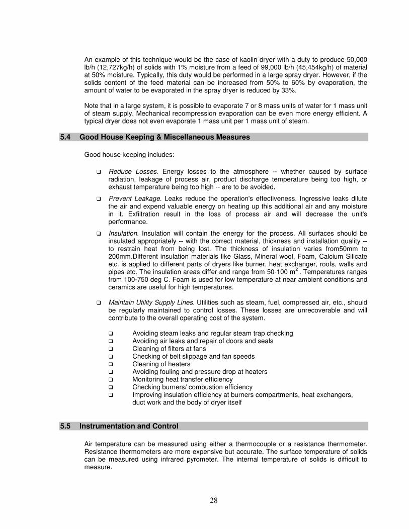
Air humidity can be measured buy wet-bulb and dry-bulb thermometers. Resistance sensors, which consists of an absorbent material whose resistance changes with moisture content. Absorption capacitive sensors consist of a parallel plate capacitor whose dielectric is sensitive to humidity. Material used is usually aluminum oxide doped with lithium chloride. The commonly used control methods are discussed below. In manual control systems, at some point downstream of the dryer exit, the operator measures the moisture content of the material and compares the same with desired value. Then the energy input/feed rate is adjusted to get desired quality of drying. This type of manual feed back control is seen in many plants, they are simple and less expensive. But they are not effective especially when good control is required. If the adjustments to energy input/feed rate etc are made automatically in a closed loop control scheme, the variations in moisture contents can be limited. The above control systems (manual and automatic) do not effectively tackle the disturbances at the input. For example, a 1 Tph dryer suddenly operates at 50% of the load and if the inlet moisture content is higher, in the above control systems, though work hard to give desired moisture content, the energy consumption is not optimised. Hence a feed forward control system which measures all the above parameters is used when lot of variations are expected. In a feed forward control system, it is necessary to include a feed rate sensor/transmitter and an inlet moisture content transmitter/transmitter. From the sensed parameters, the controller calculates the material and energy balance and estimate the quantity of water to be evaporated and the fuel quantity required. The estimated fuel quantity requirement is compared with the actual fuel flow rate and this difference is used to correct the moisture content. Costs of these systems would be 3 to 4 times cost of a manual control system. The measurement of feed rate and inlet moisture content is necessary because the actual moisture content of the material inside the dryer is not generally available. This value, if measured would be representative of the inlet variations, for a given energy input. A relatively advanced control-Delta T Dryer Control- has temperature probes continually measure the moisture content of the product inside the dryer during the drying cycle and readjust the time and temperature of the dryers accordingly. The control variable is delta T. The exact definition depends on the type of drying. It is usually defines as the change in temperature of air before and after contact with product. In batch drying, it may be defined as the temperature of entering hot air minus the temperature air leaving the dryer. The dryer works using a mathematical equation to continually adjust the temperature based on information provided by the temperature probes. Customized control mechanisms have been created to work within the wide variety of dryers in manufacturing including conveyor, rotary, flash, fluidized bed, and rotary louver. A schematic of hot air drying in carpet drying is given below in fig 5.1. RTDs are used to measure hot end temperature (T-hot) and cold end temperature (T-cold). The resulting temperature drop is used as a process measurement to relate to moisture content. A change in conveyor speed or energy input can be made based on the temperature drop.
30
Figure 5-1: Delta T control system for hot air drying
5.6 Technical Modification / Selection of drying method
Direct Heating: Direct fired dryers are more efficient than indirectly heated dryers. Direct heating can reduce using steam/ thermic fluid about 35 to 45% of the primary fuel requirement. Apart from use of hot combustion gases exhaust of gas turbine from combined heat power project or gas fired infrared heating can also be used. The application will depend on retrofit modification needed in existing dryer and nature of the material to be dried. Drying and curing using natural gas direct firing with individual zone control, in place of steam system in a stenter is an example of using direct heating. Using CHP exhaust gases in fluidised bed drying directly is also done to utilise direct heating principles. Electro-Magnetic Heating: Some of the material take long drying time because of their bulk and thickness. Sometimes there is a possibility of non-uniform drying or damage. In such cases a targeted drying of moisture in the material results in faster and more efficient drying and better audit of product. Infrared heating, induction heating and dielectric heating (Radio Frequency and Microwave Drying) can be used in such cases for direct delivery of electromagnetic energy to the solid or moisture.
5.7 Use the Exhaust Air Effectively.
The humidity of exhaust air is well below its equilibrium value, in relation to the moisture content of the material being dried. This means that it has removed less water that material than it can and that more heat is used to heat the air than necessary. For example, suppose if the equilibrium humidity content of exhaust air is 0.1 kg/kg dry basis, but the actual humidity of exhaust air is 0.02 kg/kg of dry air. Then for a flow rate of 50 kg/s of dry air, the same rate of water removal could be theoretically achieved with 10 kg/s of dry air. The remaining 40 kg/s is not needed for drying the material. Energy used for heating this air is wasted. However, it is always not possible to do that, because the rate of drying is proportional to the difference between the equilibrium and the actual humidity.
31
Heat recovery is the simplest method of retrofit modification of dryer to enhance its efficiency. The major methods are as follows: � Recycling of exhaust air � Use of recuperators, heat wheels, plate heat exchangers run-around coils Heat recovery is used with rotary, spray, fluid-bed and conveyor/band dryers in chemicals, mineral and food industries. These are also used in textile dryers like stenters and paper machine dryers.
Recycling. Recycling the air within the dryer reduces the sensible requirements to heat the air from its atmospheric condition to the operating condition. Recycling involves redirecting the exhaust air or a portion thereof, back into the process. Limiting factors for recycling will include saturation of the gas and depletion of the oxygen content of the gas (for direct-fired applications). They can be overcome by controlling the percentage recycle.
Recuperation. The use of recuperation to preheat the feed product, inlet air or combustion air offers additional advantages. This same concept also could be used as the source of energy to preheat the product. Recuperators can be air-to-air, air to solid, or air to liquid units. Some recuperators may be relatively large and will absorb a certain amount of power (from the fans) to overcome losses associated with the equipment.
5.8 Final Moisture Content Specification.
In many instances, the product's final moisture content can be increased without any detrimental effect on the post process. Easing this requirement can significantly improve the overall production. As an alternative, it may be advantageous to install a second dryer to remove the last, small fraction of moisture. Frequently referred to as two-stage drying, this approach offers benefits in both energy consumed and production due to reduced airflows and heat requirements for such a small fraction of moisture removal.
32
6 CASE STUDIES
6.1 Reduction in demand of steam in belt dryer system
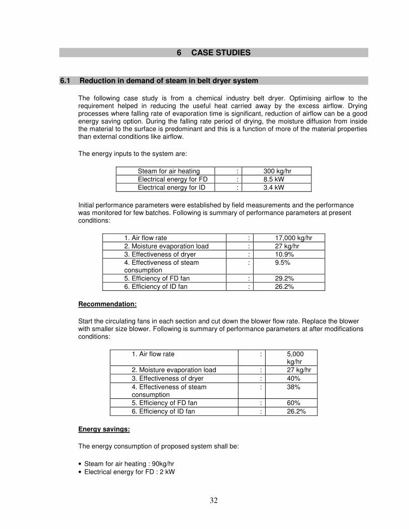
The following case study is from a chemical industry belt dryer. Optimising airflow to the requirement helped in reducing the useful heat carried away by the excess airflow. Drying processes where falling rate of evaporation time is significant, reduction of airflow can be a good energy saving option. During the falling rate period of drying, the moisture diffusion from inside the material to the surface is predominant and this is a function of more of the material properties than external conditions like airflow.
The energy inputs to the system are:
Steam for air heating : 300 kg/hr Electrical energy for FD : 8.5 kW Electrical energy for ID : 3.4 kW
Initial performance parameters were established by field measurements and the performance was monitored for few batches. Following is summary of performance parameters at present conditions:
1. Air flow rate : 17,000 kg/hr 2. Moisture evaporation load : 27 kg/hr 3. Effectiveness of dryer : 10.9% 4. Effectiveness of steam consumption
: 9.5%
5. Efficiency of FD fan : 29.2% 6. Efficiency of ID fan : 26.2%
Recommendation:
Start the circulating fans in each section and cut down the blower flow rate. Replace the blower with smaller size blower. Following is summary of performance parameters at after modifications conditions:
1. Air flow rate : 5,000 kg/hr
2. Moisture evaporation load : 27 kg/hr 3. Effectiveness of dryer : 40% 4. Effectiveness of steam consumption
: 38%
5. Efficiency of FD fan : 60% 6. Efficiency of ID fan : 26.2%
Energy savings:
The energy consumption of proposed system shall be:
• Steam for air heating : 90kg/hr • Electrical energy for FD : 2 kW
33
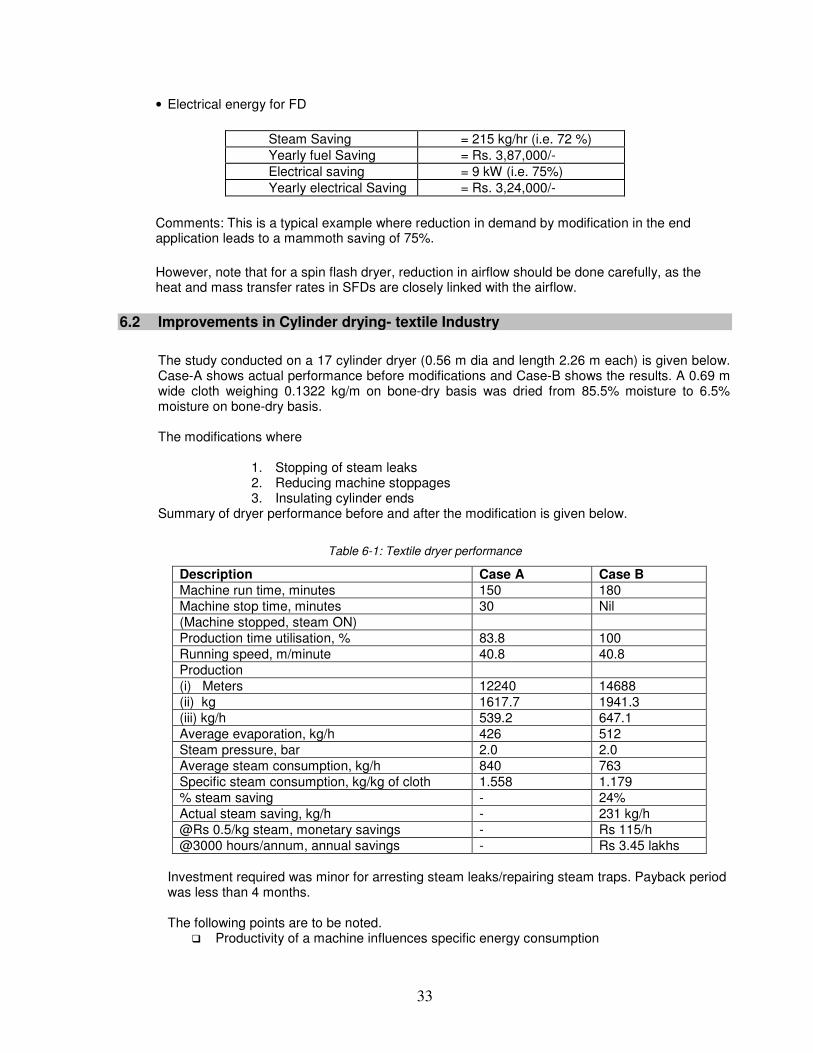
• Electrical energy for FD
Steam Saving = 215 kg/hr (i.e. 72 %) Yearly fuel Saving = Rs. 3,87,000/- Electrical saving = 9 kW (i.e. 75%) Yearly electrical Saving = Rs. 3,24,000/-
Comments: This is a typical example where reduction in demand by modification in the end application leads to a mammoth saving of 75%.
However, note that for a spin flash dryer, reduction in airflow should be done carefully, as the heat and mass transfer rates in SFDs are closely linked with the airflow.
6.2 Improvements in Cylinder drying- textile Industry
The study conducted on a 17 cylinder dryer (0.56 m dia and length 2.26 m each) is given below. Case-A shows actual performance before modifications and Case-B shows the results. A 0.69 m wide cloth weighing 0.1322 kg/m on bone-dry basis was dried from 85.5% moisture to 6.5% moisture on bone-dry basis. The modifications where
1. Stopping of steam leaks 2. Reducing machine stoppages 3. Insulating cylinder ends
Summary of dryer performance before and after the modification is given below.
Table 6-1: Textile dryer performance
Description Case A Case B
Machine run time, minutes 150 180 Machine stop time, minutes 30 Nil (Machine stopped, steam ON) Production time utilisation, % 83.8 100 Running speed, m/minute 40.8 40.8 Production (i) Meters 12240 14688 (ii) kg 1617.7 1941.3 (iii) kg/h 539.2 647.1 Average evaporation, kg/h 426 512 Steam pressure, bar 2.0 2.0 Average steam consumption, kg/h 840 763 Specific steam consumption, kg/kg of cloth 1.558 1.179 % steam saving - 24% Actual steam saving, kg/h - 231 kg/h @Rs 0.5/kg steam, monetary savings - Rs 115/h @3000 hours/annum, annual savings - Rs 3.45 lakhs
Investment required was minor for arresting steam leaks/repairing steam traps. Payback period was less than 4 months. The following points are to be noted.
� Productivity of a machine influences specific energy consumption
34
� First priority should be given to stopping all live steam leakages through trap and rotary joints
� Steam consumption could have been further reduced if incoming moisture was reduced to 60 to 70% level instead of 85.5%.
� Practically about 1.6 to 1.8 kg steam/kg evaporation is required in cylinder drying
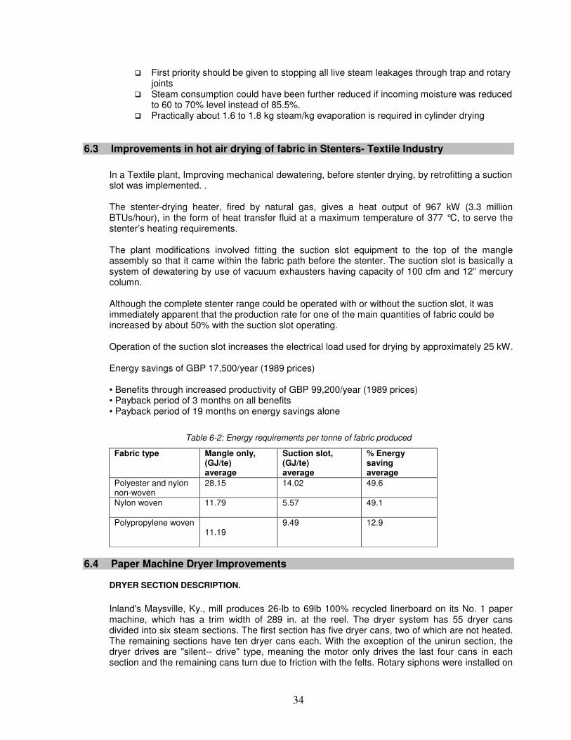
6.3 Improvements in hot air drying of fabric in Stenters- Textile Industry
In a Textile plant, Improving mechanical dewatering, before stenter drying, by retrofitting a suction slot was implemented. . The stenter-drying heater, fired by natural gas, gives a heat output of 967 kW (3.3 million BTUs/hour), in the form of heat transfer fluid at a maximum temperature of 377 °C, to serve the stenter’s heating requirements. The plant modifications involved fitting the suction slot equipment to the top of the mangle assembly so that it came within the fabric path before the stenter. The suction slot is basically a system of dewatering by use of vacuum exhausters having capacity of 100 cfm and 12” mercury column. Although the complete stenter range could be operated with or without the suction slot, it was immediately apparent that the production rate for one of the main quantities of fabric could be increased by about 50% with the suction slot operating. Operation of the suction slot increases the electrical load used for drying by approximately 25 kW. Energy savings of GBP 17,500/year (1989 prices) • Benefits through increased productivity of GBP 99,200/year (1989 prices) • Payback period of 3 months on all benefits • Payback period of 19 months on energy savings alone
Table 6-2: Energy requirements per tonne of fabric produced
Fabric type Mangle only, (GJ/te) average
Suction slot, (GJ/te) average
% Energy saving average
Polyester and nylon non-woven
28.15
14.02
49.6
Nylon woven 11.79
5.57
49.1
Polypropylene woven 11.19
9.49
12.9
6.4 Paper Machine Dryer Improvements
DRYER SECTION DESCRIPTION.
Inland's Maysville, Ky., mill produces 26-lb to 69lb 100% recycled linerboard on its No. 1 paper machine, which has a trim width of 289 in. at the reel. The dryer system has 55 dryer cans divided into six steam sections. The first section has five dryer cans, two of which are not heated. The remaining sections have ten dryer cans each. With the exception of the unirun section, the dryer drives are "silent-- drive" type, meaning the motor only drives the last four cans in each section and the remaining cans turn due to friction with the felts. Rotary siphons were installed on
35
all dryers at startup in 1992. The third and fourth section dryer cans were also equipped with turbulence bars.
The mill uses a recirculating thermocompressor differential pressure control system to remove condensate from the dryer cans.With this system, condensate is drawn out of the dryer cans, since a lower pressure is maintained in the condensate flash tanks.
To maintain the differential pressure, the blow through steam is recirculated into a thermocompressor where it is recompressed and injected into the steam header.When the thermocompressor valve is wide open and differential pressure is still below set point, excess steam is discharged to the off-machine silos for heating. When the silo valve is wide open and the differential pressure is still below set point, the blow through steam is then vented to the atmosphere.
Dryer Flooding Challenges. As the Maysville mill's No. 1 paper machine was optimized and production increased, dryer flooding became increasingly problematic. The mill's paper yield task team identified several issues associated with this flooding:
Energy loss. Dryer can flooding caused extensive energy loss. Differential pressures as high as 18 psi in the early dryer sections were required to evacuate the dryer cans.This resulted in excessive blow through steam. Also, venting was a serious problem during production of linerboard weights of 33 lb and lower.
Machine speed limitations. Dryer flooding limited machine speed on the No. 1 paper machine. When the dryer drive motors became loaded due to dryer flooding, the machine speed was reduced to regain normal operation.This occurred when producing linerboard weights of 42 lb and heavier. Also, when dryer cans flooded during operations, it could take as long as ten hours to drain them.
Delayed threading. Dryer flooding during sheet breaks delayed threading and extended the time required to bring the machine back up to speed. Leaking steam valves caused dryer flooding in all the sections. The second section flooded in minutes after shutdown, because the silent-drive allowed the rotary siphons to stop at positions other than six o'clock. This section took 30 minutes to one hour to drain during a shutdown. During startup, dryer flooding delayed threading and caused repeated drive trips while the section was brought up to speed.
Felt wear Dryer flooding caused excessive wear on the silent-drive felts of the second section. Flooded dryers in the second section required more force from the felts to turn them. By 1997, the felts on the second section that had an expected life of 200 days were splitting at the seams within 60 days.
Stationary Siphons. The use of rotary siphons in the silent-drive second section had been a concern since the 1992 startup of the No. 1 paper machine.The stationary siphons on the market at that time were considered unreliable due to siphon shoe erosion, vibration, and other mechanical problems. However, by 1998, stationary siphons were considered a reliable, efficient, and low-maintenance alternative to rotary siphons.
The paper yield task team investigated stationary siphons as a means to reduce the mill's dryer flooding problems. Because condensate does not have to resist centrifugal forces to exit the dryer cans through stationary siphon systems, less differential pressure is required to evacuate condensate out of the cans. Consequently, there is less blow through steam and steam venting.
The stationary siphons are particularly suitable for use on silent-drive sections, where rotary siphons may not stop in the six o'clock position during shutdowns. The paper yield task team
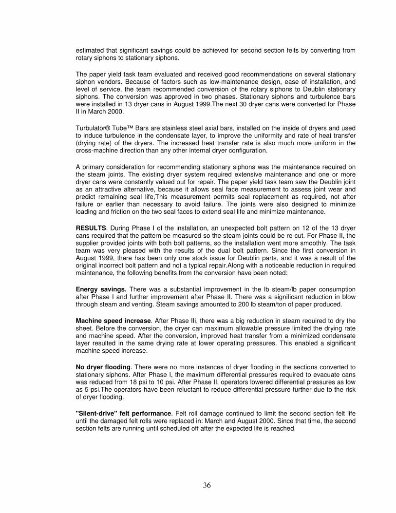
36
estimated that significant savings could be achieved for second section felts by converting from rotary siphons to stationary siphons.
The paper yield task team evaluated and received good recommendations on several stationary siphon vendors. Because of factors such as low-maintenance design, ease of installation, and level of service, the team recommended conversion of the rotary siphons to Deublin stationary siphons. The conversion was approved in two phases. Stationary siphons and turbulence bars were installed in 13 dryer cans in August 1999.The next 30 dryer cans were converted for Phase II in March 2000.
Turbulator® Tube™ Bars are stainless steel axial bars, installed on the inside of dryers and used to induce turbulence in the condensate layer, to improve the uniformity and rate of heat transfer (drying rate) of the dryers. The increased heat transfer rate is also much more uniform in the cross-machine direction than any other internal dryer configuration.
A primary consideration for recommending stationary siphons was the maintenance required on the steam joints. The existing dryer system required extensive maintenance and one or more dryer cans were constantly valued out for repair. The paper yield task team saw the Deublin joint as an attractive alternative, because it allows seal face measurement to assess joint wear and predict remaining seal life,This measurement permits seal replacement as required, not after failure or earlier than necessary to avoid failure. The joints were also designed to minimize loading and friction on the two seal faces to extend seal life and minimize maintenance.
RESULTS. During Phase I of the installation, an unexpected bolt pattern on 12 of the 13 dryer cans required that the pattern be measured so the steam joints could be re-cut. For Phase II, the supplier provided joints with both bolt patterns, so the installation went more smoothly. The task team was very pleased with the results of the dual bolt pattern. Since the first conversion in August 1999, there has been only one stock issue for Deublin parts, and it was a result of the original incorrect bolt pattern and not a typical repair.Along with a noticeable reduction in required maintenance, the following benefits from the conversion have been noted:
Energy savings. There was a substantial improvement in the lb steam/lb paper consumption after Phase I and further improvement after Phase II. There was a significant reduction in blow through steam and venting. Steam savings amounted to 200 lb steam/ton of paper produced.
Machine speed increase. After Phase IIi, there was a big reduction in steam required to dry the sheet. Before the conversion, the dryer can maximum allowable pressure limited the drying rate and machine speed. After the conversion, improved heat transfer from a minimized condensate layer resulted in the same drying rate at lower operating pressures. This enabled a significant machine speed increase.
No dryer flooding. There were no more instances of dryer flooding in the sections converted to stationary siphons. After Phase I, the maximum differential pressures required to evacuate cans was reduced from 18 psi to 10 psi. After Phase II, operators lowered differential pressures as low as 5 psi.The operators have been reluctant to reduce differential pressure further due to the risk of dryer flooding.
"Silent-drive" felt performance. Felt roll damage continued to limit the second section felt life until the damaged felt rolls were replaced in: March and August 2000. Since that time, the second section felts are running until scheduled off after the expected life is reached.
37
6.5 Paper machine dryer modifications and improved control system
A case history was presented on the No. 26 Stora Enso Biron paper machine DMS ( Dryer management System) installation (also profiled in the July 2004 issue of Pulp & Paper, p. 45). The No. 26 unit is a Voith lightweight coated machine with two on-machine coalers. The machine produces 30- to 45-lb (45- to 65-gsm) grades at speeds up to 4,200 fpm (1,280 mpm). Phase I of the rebuild, completed in June 2003, included modifying the steam and condensate system and installing the DMS. Wet end steam joints and syphons were replaced in May 2004. The remaining steam joints and syphons were replaced in January 2005. Wisconsin Focus on Energy funded a Johnson Systems dryer section study to identify potential energy savings. Results from the system installation included:
� Consistency of steam and condensate system operation greatly improved
� Annual energy savings of $75,000
� Dryer flooding eliminated
� System startups are reliable; sheet break recovery time reduced by three to four minutes
� Reduced maintenance adds up to $90,000 savings annually
� Raw stock sheet threading has improved
� Less shift-to-shift variability of the paper produced
� Improved coater tail threading due to calculation of required steam pressure
� Total annual savings of $263,000 due to reduced energy consumption, lower maintenance
cost, and higher production.
� Project payback was seven months.
6.6 Heat recovery from exhaust gas in a spray dryer- Chemical Industry
A spray dryer having 400 tons/h water evaporation capacity is used to dry inorganic salts. The input air is heated by direct gas firing to between 200 and 300 C. The feedstock was having initial temperature between 20 and 60 C and a moisture content of 40 to 60% by weight. The feedstock enters the dryer through a rotating disk atomiser. The dried solid is separated from the exhaust air in a cyclone. The exhaust air has an average temperature between 100 to 112 C. A heat exchanger was installed to recover heat from the exhaust air, to preheat the incoming air. A schematic of the system after modification is given below in fig 6.1.
38
Figure 6-1: Heat recovery- Spray Dryer
The heat recovery device used was a glass tube recuperator. The dryer exhaust air flows upwards through the inside of the tubes. The glass tubes were used essentially to prevent corrosion of tubes due to salty vapors. It was found that after the installation of heat exchanger, the gas consumption in dryer was found to reduce from 60.7 m3/h to 40.6 m3/h. For an average production rate of 300 kg/hr dry products, the specific energy consumption reduced from 6.6 MJ/kg to 5 MJ/kg.
6.7 Waste Heat Recovery from CHP
The site consists of underground mines and a nickel concentrator.
The plant utilised three diesel fired spray dryers for drying nickel concentrate from a moisture concentration of approximately 30% down to 0.5%. In 1996 approximately 250,000 tonnes of nickel concentrate was dried utilising around 8.5 million litres of diesel. This provided an efficiency of drying of around 1.3 GJ per tonne of concentrate dried.
In 1997, the plant commissioned a 42 MW gas turbine and a project for utilisation of the waste heat available from the turbine exhaust gases for drying of nickel concentrate was commissioned.
Following the commissioning of the gas turbines and subsequent utilisation of the waste heat gas diesel usage dropped significantly. Natural gas was then used in place of diesel for the supplementary firing required beyond the heat available from the gas turbine exhaust. By 1998 the production throughput had increased to around 300,000 tonnes of concentrate. With the use of the available waste heat and the conversion to natural gas supplementary firing energy had been reduced to below 0.4 GJ per tonne of nickel concentrate dried. This represented a reduction in fuel use of approximately 270 TJ of diesel.
6.8 Energy saving in Spin Flash Dryer System-Blower: Chemical Industry
The plant manufactures CPC blue powder. The cakes from the filter press are manually conveyed to the dryer. Heat source of dryer is thermic fluid circulated coils. Drying time was 4 hours.
39
The blower draws atmospheric air through a filter and the heating coils into the dryer and exhausts out through bag filters located after the dryer. The blower was rated for 75 HP. Airflow was measured to be about 22,000 m3/h and actual power input to the blower was 51.5 kW. The blower operating speed was 2400 rpm with a pulley diameter of 8.5 “and motor side pulley of 12” dia. During the study, it was noted that the suction damper of the blower is partially closed. It was suggested to avoid damper control and reduce the speed of the blower to save energy. Initially the blower speed was reduced to 1700 rpm. Operation of the dryer was observed to ensure production and quality parameters. It was found that that the drying time was increased by 20%. This was not acceptable. Clearly, airflow has reduced due to the fact that speed reduction was not optimum. A 12” pulley was installed on motor and operation of the dryer was observed. Blower speed is now 2000 rpm. Power input was 41.5 kW. There was no change in production time or quality and hence the measure was accepted. Total energy saving was 80000 kWh/annum. I.e. Rs 3.7 lakhs/annum. Investment for new pulley was only Rs 10,000/- with a payback period of 10 days.
6.9 Improved Mechanical dewatering to save energy in Rotary Dryer- Beet Sugar Industry
This case study from a British Sugar Mill shows that the energy requirements of removing moisture by mechanical dewatering techniques are generally insignificant compared with those needed to evaporate moisture. This means that as much moisture as possible should be removed mechanically (i.e. pressing, filtering, sedimentation, etc.) prior to entering a dryer, especially if the initial moisture content is high. This principle can be illustrated by the use of screw presses in processing pulp, a by-product of the extraction of sugar from sugar beet that is used as cattle fodder. Sugar beet to be processed was cut into thin slices before going into the diffuser where the sugar was extracted. The remaining pulp was sent to screw presses, which reduced its moisture content from 8.5 to 2.3 kg/kg (dry basis). After pressing, molasses were added to increase the nutritional value of the pulp which was then sent to rotary dryers to be dried to a final moisture content of 0.3 kg/kg (dry basis). The plant operated 6 presses and 3 rotary dryers for this purpose. The water expelled from the wet beet pulp by pressing was 8.69 kg/s. Each press required approximately 0.2 MW of electrical power. Hence the specific energy consumption of removing water using a screw press was 21.1 kJ/kg of water. The evaporation rate in the rotary dryer was 6.88 kg/s. The evaporation of 6.88 kg/s of water in a single rotary dryer required 20 MW from a direct fired heater. Therefore the specific energy consumption of removing water in the rotary dryer was 2,840 kJ/kg. The percentage energy saving by using mechanical dewatering was therefore: 8.69
6.88 + 8.69 = 55.8%
40
ANNEXURE-1: Description of terms
Terms related to drying materials
• Feed: Wet input material to the dryer is termed as feed.
• Hygroscopic /non hygroscopic materials: material that has ability to absorb and bind
moisture by hygroscopic forces (depending on nature of the product and temperature/ humidity of the surroundings is termed as hygroscopic. Material, which does not contain any bound moisture, is called non-hygroscopic.
Terms related to level/nature of moisture in drying materials
• Bone Dry Material: Any material, which has been dried at sufficiently high temperature for a
prolonged time by well-established methods till it is deviled of all traces of moisture, is called ‘Bone Dry Material’.
• Moisture Content: The loss of moisture under standard prescribed drying condition till bone-
dry stale is reached is termed as the ‘moisture content’ of the material and is usually expressed as a fraction of moisture per kg of wet material (wet basis) or expressed as fraction of moisture per kg of bone-dry material (bone dry basis). Moisture refers to water, although other liquids may follow the same testing techniques.
• Equilibrium moisture content: It is the level of bound moisture in a given material which is
attained on stabilization under specified conditions of temperature and humidity either by loosing excess moisture by drying or by absorbing moisture from surroundings.
• Bound Moisture: Liquid bound in the solid in its capillaries, by solution in its cells/walls, by
solution and by chemical/physical adsorption.
• Free moisture: In a hygroscopic material, it is the moisture in excess of the equilibrium moisture content at existing humidity and temperature and includes unbound as well as bound moisture which can be removed.
Terms related to drying process
• Periods of Drying: As drying proceeds, moisture content and rate of drying change with
respect to time as follows.
Initially the moisture evaporates from the saturated surface of a solid. In this phase, the rate of drying per unit drying area is CONSTANT. At the end of this, there is a decrease in the area of saturated surface and a transition level called CRITICAL MOISTURE CONTENT is reached. Finally, the water diffuses from the interior and then evaporates. In this phase called FALLING RATE PERIOD of drying, the instantaneous rate of drying continuously decreases. The drying curve is a graphical representation of moisture content of the product vs. time during the process of drying and it identifies the constant, critical and falling rate regimes of drying.
41
Terms Related to Heat and Mass Transfer/Psychrometric Processes.
• Absolute Humidity: It is the amount of liquid (e.g. water) vapour in a given gas stream
expressed as weight of liquid per weight of dry gas, expressed as kg of liquid /kg of dry air • Relative Humidity: It is the ratio of the partial pressure of the condensable vapour in the gas
to the vapour pressure of the pure vapour at the same temperature expressed as a percentage.
• Wet Bulb Temperature: It is the dynamic equilibrium temperature attained by a liquid
surface when the rate of heat transfer to the surface by convection equals the rate of mass transfer away from the surface.
• Sensible heat: It is the energy involved in changing the temperature of a given substance.
• Latent heat: It is the energy involved in a phase change (e.g. liquid to vapour), which does
not result in a temperature change, expressed as kJ/kg.
• Humid Heat: Is the heat necessary to cause a unit temperature increase in a unit mass of humid air (dry air + moisture)
• Material Balance: It is an account of material entering a system, which must equal the
material leaving a system if no hold up occurs. Care must be taken to account for the various means through which material can leave a system. For example, in a spray dryer, dried powder can come out through the main dryer as well as though the dust collector.
• Heat Balance: It is an account of the heat supplied to the system and the heat used. The
heat required in the dryer is generally made up of the following:
• Sensible heat to for raising the material to the drying temperature. • Heat required for raising the temperature and then the evaporation of the liquid • Heat losses through the equipment losing by radiation and convection. • Heat lost in exhaust or due to air leakage and in the rejected heating medium like
condensate if it is not recovered/recycled.
• Thermal Efficiency: Is the percentage of total energy supply that is used to evaporate water (or solvent).
Equipments:
The letter symbols in the code may be used with appropriate subscript, which may designate a place in space or time a system of units or a constant or reference value. The terminology refers principally to the unit operation of drying to remove water, though often drying of other solvents is also involved.
The definitions conform generally to common usage but as there are many types of dryers and many modes of dryer operation there are exceptions to some definitions.
• Dryer: It is an assembly of equipments used for removal of moisture from solids by
evaporation.
42
• Continuous Dryers: These are those in which the feed, moisture evaporations are continuous and uniform
• Batch Dryers: These are those in which either the feed operation or discharge operation or
both are intermittent.
• Direct Dryers: Heat is transferred from hot gases by direct contact with wet solids. Hot gases carry the vaporized liquid away. These are hot-air/convection dryers.
• Indirect Dryers: Heat is transferred to the wet solid through a retaining wall. The rate of drying
depends on good contact of wet materials with hot surfaces. These are conduction/contact dryers.
43
REFERENCES
1. Energy Conservation in Pulp & Paper Industry- CADDET Analysis Series, Netherlands 2. APV Dryer Handbook-Invensys APV Technical Centre, USA 3. Handbook of Drying Technologies- Arun Mujumdar-Marcel Decker Publications 4. Chemical Engineering handbook- Perry 5. Industrial Drying- A. Williams Gardner- George Godwin Ltd.
Related Documents