*26862719_0121* Drive Technology \ Drive Automation \ System Integration \ Services Manual DriveRadar ® DataCollector Edition 01/2021 26862719/EN

Welcome message from author
This document is posted to help you gain knowledge. Please leave a comment to let me know what you think about it! Share it to your friends and learn new things together.
Transcript

*26862719_0121*Drive Technology \ Drive Automation \ System Integration \ Services
Manual
DriveRadar® DataCollector
Edition 01/2021 26862719/EN
SEW-EURODRIVE—Driving the world

Table of contents
Manual – DriveRadar® DataCollector 3
Table of contents1 General information.................................................................................................................. 5
1.1 About this documentation ............................................................................................... 51.2 Content of the documentation......................................................................................... 51.3 Other applicable documentation ..................................................................................... 51.4 Short designation ............................................................................................................ 51.5 Structure of the warning notes ........................................................................................ 6
1.5.1 Meaning of signal words ................................................................................ 61.5.2 Structure of section-related safety notes........................................................ 61.5.3 Structure of embedded safety notes .............................................................. 6
1.6 Decimal separator in numerical values ........................................................................... 71.7 Rights to claim under limited warranty ............................................................................ 71.8 Product names and trademarks...................................................................................... 7
1.8.1 Trademark of Beckhoff Automation GmbH .................................................... 71.9 Copyright notice .............................................................................................................. 7
2 Safety notes .............................................................................................................................. 82.1 Preliminary information ................................................................................................... 82.2 Target group ................................................................................................................... 82.3 Network security and access protection ......................................................................... 82.4 Designated use ............................................................................................................... 8
3 System description .................................................................................................................. 93.1 Introduction ..................................................................................................................... 93.2 Functions ........................................................................................................................ 93.3 Operating principle........................................................................................................ 103.4 Added value .................................................................................................................. 10
4 Project planning information................................................................................................. 114.1 Requirement ................................................................................................................. 114.2 Hardware ...................................................................................................................... 114.3 Software........................................................................................................................ 114.4 Licensing....................................................................................................................... 12
5 Installation............................................................................................................................... 13
6 User interface.......................................................................................................................... 156.1 Start screen................................................................................................................... 15
6.1.1 Displaying frequency inverters ..................................................................... 156.1.2 Displaying controllers ................................................................................... 16
6.2 Configuration editor....................................................................................................... 16
7 Settings.................................................................................................................................... 177.1 Language ...................................................................................................................... 177.2 Options.......................................................................................................................... 177.3 Meta data ...................................................................................................................... 19
8 Startup ..................................................................................................................................... 208.1 Startup procedure ......................................................................................................... 208.2 Scope templates ........................................................................................................... 20
2686
2719
/EN
– 0
1/20
21
Table of contents
Manual – DriveRadar® DataCollector4
8.2.1 Configuring scope ........................................................................................ 208.2.2 Saving scope as template............................................................................ 22
8.3 Device list...................................................................................................................... 238.3.1 Device configuration..................................................................................... 238.3.2 Grouping devices ......................................................................................... 288.3.3 Saving the configuration............................................................................... 30
9 Operation................................................................................................................................. 319.1 Operating modes .......................................................................................................... 319.2 Activating manual mode................................................................................................ 319.3 Initializing devices......................................................................................................... 319.4 Starting automatic mode ............................................................................................... 32
10 Appendix ................................................................................................................................. 3310.1 IIoT sensor technology properties (extract) .................................................................. 3310.2 Sample topologies ........................................................................................................ 34
10.2.1 Data acquisition via PROFINET................................................................... 3410.2.2 Data acquisition via Wi-Fi............................................................................. 3410.2.3 Data acquisition via SEW system bus and gateway .................................... 3510.2.4 Data acquisition of single parameters .......................................................... 35
Index ........................................................................................................................................ 36
2686
2719
/EN
– 0
1/20
21
1General informationAbout this documentation
Manual – DriveRadar® DataCollector 5
1 General information1.1 About this documentation
This documentation is an integral part of the product. The documentation is intendedfor all employees who perform work on the product.Make sure this documentation is accessible and legible. Ensure that persons respon-sible for the systems and their operation as well as persons who work with the productindependently have read through the documentation carefully and understood it. If youare unclear about any of the information in this documentation, or if you require furtherinformation, contact SEW‑EURODRIVE.
1.2 Content of the documentationThe descriptions in this documentation apply to the software and firmware versionsapplicable at the time of publication. These descriptions might differ if you install latersoftware or firmware versions. In this case, contact SEW‑EURODRIVE.
1.3 Other applicable documentationObserve the corresponding documentation for all further components.Always use the latest edition of the documentation and the software.The SEW‑EURODRIVE website (www.sew‑eurodrive.com) provides a wide selectionof documents for download in various languages. If required, you can also order prin-ted and bound copies of the documentation from SEW‑EURODRIVE.
1.4 Short designationThe following short designations are used in this documentation.
Designation Short designationDriveRadar® DataCollector Software
Industrial Internet of Things IIoT
2686
2719
/EN
– 0
1/20
21
1 General informationStructure of the warning notes
Manual – DriveRadar® DataCollector6
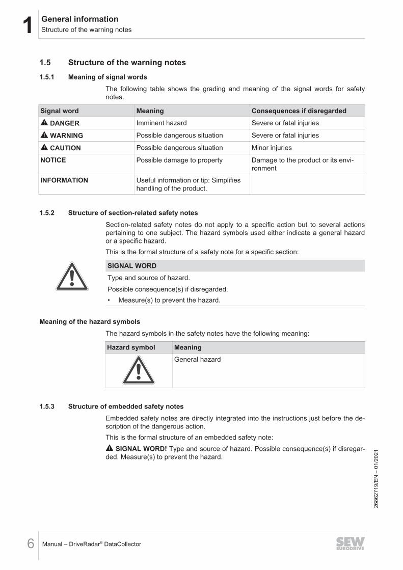
1.5 Structure of the warning notes1.5.1 Meaning of signal words
The following table shows the grading and meaning of the signal words for safetynotes.
Signal word Meaning Consequences if disregarded
DANGER Imminent hazard Severe or fatal injuries
WARNING Possible dangerous situation Severe or fatal injuries
CAUTION Possible dangerous situation Minor injuries
NOTICE Possible damage to property Damage to the product or its envi-ronment
INFORMATION Useful information or tip: Simplifieshandling of the product.
1.5.2 Structure of section-related safety notesSection-related safety notes do not apply to a specific action but to several actionspertaining to one subject. The hazard symbols used either indicate a general hazardor a specific hazard.This is the formal structure of a safety note for a specific section:
SIGNAL WORDType and source of hazard.Possible consequence(s) if disregarded.• Measure(s) to prevent the hazard.
Meaning of the hazard symbolsThe hazard symbols in the safety notes have the following meaning:
Hazard symbol MeaningGeneral hazard
1.5.3 Structure of embedded safety notesEmbedded safety notes are directly integrated into the instructions just before the de-scription of the dangerous action.This is the formal structure of an embedded safety note:
SIGNAL WORD! Type and source of hazard. Possible consequence(s) if disregar-ded. Measure(s) to prevent the hazard.
2686
2719
/EN
– 0
1/20
21

1General informationDecimal separator in numerical values
Manual – DriveRadar® DataCollector 7
1.6 Decimal separator in numerical values
In this document, a period is used to indicate the decimal separator.Example: 30.5 kg
1.7 Rights to claim under limited warrantyRead the information in this documentation. This is essential for fault-free operationand fulfillment of any rights to claim under limited warranty. Read the documentationbefore you start working with the product.
1.8 Product names and trademarks
The brands and product names in this documentation are trademarks or registeredtrademarks of their respective titleholders.
1.8.1 Trademark of Beckhoff Automation GmbHEtherCAT® is a registered trademark and patented technology, licensed by BeckhoffAutomation GmbH, Germany.
1.9 Copyright notice
© 2021 SEW‑EURODRIVE. All rights reserved. Unauthorized reproduction, modifica-tion, distribution or any other use of the whole or any part of this documentation isstrictly prohibited.
2686
2719
/EN
– 0
1/20
21
2 Safety notesPreliminary information
Manual – DriveRadar® DataCollector8
2 Safety notes2.1 Preliminary information
The following general safety notes serve the purpose of preventing injury to personsand damage to property. They primarily apply to the use of products described in thisdocumentation. If you use additional components, also observe the relevant warningand safety notes.
2.2 Target group
Software specialist Any work with the software may only be performed by a specialist with suitable train-ing. A specialist in this context is someone who has the following qualifications:• Appropriate training• Knowledge of this documentation and other applicable documentation• SEW‑EURODRIVE recommends additional training for products that are operated
using this software.
2.3 Network security and access protectionA bus system makes it possible to adapt electronic drive technology components tothe particulars of the machinery within wide limits. There is a risk that a change of pa-rameters that cannot be detected externally may result in unexpected but not uncon-trolled system behavior and may have a negative impact on operational safety, systemavailability, or data security.Ensure that unauthorized access is prevented, especially with respect to Ethernet-based networked systems and engineering interfaces.Use IT‑specific safety standards to increase access protection to the ports. For a portoverview, refer to the respective technical data of the device in use.
2.4 Designated use
The DriveRadar® DataCollector is used to manually or automatically record and saveparameter data of frequency inverters and controllers from SEW‑EURODRIVE in peri-odic intervals.Observe the documentation for the components used.Unintended or improper use of the product may result in severe injury to persons anddamage to property.
2686
2719
/EN
– 0
1/20
21
3System descriptionIntroduction
Manual – DriveRadar® DataCollector 9
3 System description3.1 Introduction
Implementing a smart factory requires recording device data to obtain valuable in-sights on the state and diagnostics of machines and systems.With its automatic recording and saving of IIoT sensor data from electronic SEW drivesystems of generation B (control cabinet and decentralized drive technology), theDriveRadar® DataCollector enables easy access to the required information.The software can be set up on field customer IT systems, on edge units or SEW con-trollers. The devices are connected with the DriveRadar® DataCollector either wirelessor with cables via existing ethernet-based network channels (e.g. PROFINET, Ether-net) without hardware retrofitting.
3.2 FunctionsOverview of the software features:• Providing IIoT sensor data from SEW frequency inverters of generation B by auto-
matic or manual recording and saving of scope data• Providing IIoT sensor data from SEW frequency inverters and controllers of gener-
ation B by automatic or manual recording and saving of device parameter data• Automatic parameterization of the device scopes
The following functions can be implemented according to customer needs:
INFORMATIONContact SEW‑EURODRIVE Service for this.
• Individual could/IIoT connection e.g. based on MQTT or HTTPS as provided ser-vice within a customer-specific project.
• Data analysis and evaluation as provided service within the scope of a customer-specific agreement.
2686
2719
/EN
– 0
1/20
21
3 System descriptionOperating principle
Manual – DriveRadar® DataCollector10
3.3 Operating principleThe data extraction is performed by the MOVILINK® parameter service and the scopefunctionality and is executed as follows:
Scope data Once the configured interval elapsed, the software checks the state of the device thathas been configured for data extraction (e.g. if the scope program is currently active)and loads the defined scope template to this device.
INFORMATIONIf, during the device status check after the configured interval has elapsed, the soft-ware detects that the scope program in MOVITOOLS® MotionStudio is active, no dataextraction will occur and the interval is restarted.
If the trigger that is configured in the scope template is activated and the scope bufferis filled, the data are extracted and saved according to the settings. Afterwards, thesoftware loads the configured scope template to the device again, the scope recordingis started and the interval is restarted.
INFORMATIONIf a configured device is in "automatic mode" (→ 2 32), the scope device status ischecked every 10 minutes. If the scope program is deactivated (e.g. due to a systemfailure or similar), the software loads the configured scope template to the device andrestarts the scope recording.
Device parameterdata
A copy of device parameter data is appended to the scope recording for devices withscope function. This means a copy of the configured device parameter data is madeafter each scope recording and is stored in an additional JSON file in each case. Fordevices without scope function, the copying of device parameter data is started imme-diately after the configured interval and is also saved in an additional JSON file.
3.4 Added valueThe software offers the following benefits:• IIoT connection and optimization of existing systems with SEW drive technology
(control cabinet and decentralized drive technology)• Integration of the functionality without hardware retrofitting and without interfering
with the process sequence as it is connected via existing wireless or cable-based network communication channels (e.g. PROFINET, Ethernet). See chapter "Sample topologies" (→ 2 34).
• Providing various communication and IIoT uplink options• Recording of parameter and scope data
2686
2719
/EN
– 0
1/20
21
4Project planning informationRequirement
Manual – DriveRadar® DataCollector 11
4 Project planning information
4.1 RequirementCorrect project planning and proper installation of the components is required for suc-cessful startup and operation.For detailed project planning information, refer to the documentation of the respectivecomponents.
4.2 HardwareThe following hardware components are compatible with the software:• MOVILINK®-capable SEW devices of the generation B
(e.g. MOVIDRIVE®, MOVIMOT®)
INFORMATIONFor recording of sensor data, the software uses the Ethernet-based engineering inter-face of the devices.• In situations with a lot of access via the MOVILINK® parameter channel (e.g. par-
allel access of several communication nodes on one device) delays/bottlenecks incommunication may occur with some devices. For detailed information on com-patibility of the devices, refer the to respective documentation and chapter "IIoTsensor technology properties (extract)" (→ 2 33).
• To allow for access via other fieldbus protocols, the respective gateway must beused. For this, observe the notes and information in chapter "Sample topolo-gies" (→ 2 34).
4.3 SoftwareThe following software is required for operating the software:• Microsoft Windows (64 bits) 7 or later• Microsoft .NET 5.0 Framework
The following software is required to create scope templates:• MOVITOOLS® MotionStudio
The MOVITOOLS® MotionStudio software is available for free on theSEW‑EURODRIVE website (www.sew‑eurodrive.com).
For more detailed information on the hardware requirements of the individual softwarecomponents, see the documentation for the respective software.
2686
2719
/EN
– 0
1/20
21
4 Project planning informationLicensing
Manual – DriveRadar® DataCollector12
4.4 LicensingFor following licenses are required for operating the software:
Software license Type designationDriveRadar DataCollector B unlimited 10axes SDR0001-000
DriveRadar DataCollector B unlimited 25axes SDR0002-000
DriveRadar DataCollector B unlimited 50axes SDR0003-000
DriveRadar DataCollector B unlimited 100axes SDR0010-000
DriveRadar DataCollector B unlimited 10axes update SDR0004-000
DriveRadar DataCollector B unlimited 25axes update SDR0005-000
DriveRadar DataCollector B unlimited 50axes update SDR0006-000
DriveRadar DataCollector B unlimited 100axes update SDR0011-000
DriveRadar DataCollector B yearly 10axes SDR0007-000
DriveRadar DataCollector B yearly 25axes SDR0008-000
DriveRadar DataCollector B yearly 50axes SDR0009-000
DriveRadar DataCollector B yearly 100axes SDR0012-000
After purchasing a license, you will receive a license key. Enter the license key in the"License check" dialog when you start the software for the first time after "installa-tion" (→ 2 13).
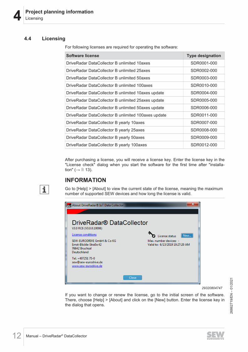
INFORMATIONGo to [Help] > [About] to view the current state of the license, meaning the maximumnumber of supported SEW devices and how long the license is valid.
29320804747
If you want to change or renew the license, go to the initial screen of the software.There, choose [Help] > [About] and click on the [New] button. Enter the license key inthe dialog that opens.
2686
2719
/EN
– 0
1/20
21
5Installation
Manual – DriveRadar® DataCollector 13
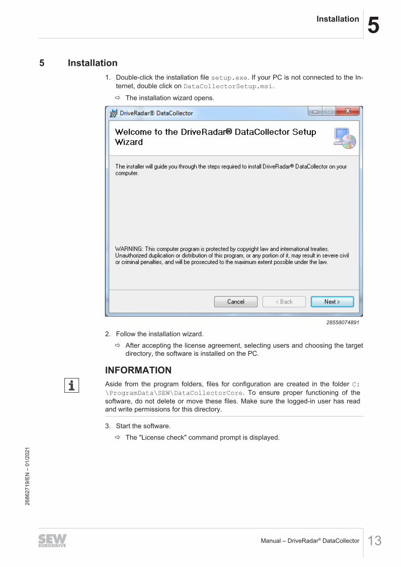
5 Installation1. Double-click the installation file setup.exe. If your PC is not connected to the In-
ternet, double click on DataCollectorSetup.msi.
ð The installation wizard opens.
28558074891
2. Follow the installation wizard.ð After accepting the license agreement, selecting users and choosing the target
directory, the software is installed on the PC.
INFORMATIONAside from the program folders, files for configuration are created in the folder C:\ProgramData\SEW\DataCollectorCore. To ensure proper functioning of thesoftware, do not delete or move these files. Make sure the logged-in user has readand write permissions for this directory.
3. Start the software.ð The "License check" command prompt is displayed.
2686
2719
/EN
– 0
1/20
21
5 Installation
Manual – DriveRadar® DataCollector14
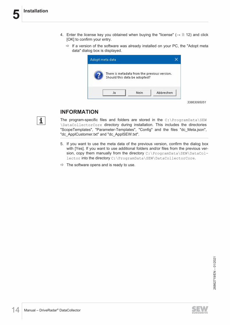
4. Enter the license key you obtained when buying the "license" (→ 2 12) and click[OK] to confirm your entry.ð If a version of the software was already installed on your PC, the "Adopt meta
data" dialog box is displayed.
33863095051
INFORMATIONThe program-specific files and folders are stored in the C:\ProgramData\SEW\DataCollectorCore directory during installation. This includes the directories"ScopeTemplates", "Parameter-Templates", "Config" and the files "dc_Meta.json","dc_ApplCustomer.txt" and "dc_ApplSEW.txt".
5. If you want to use the meta data of the previous version, confirm the dialog boxwith [Yes]. If you want to use additional folders and/or files from the previous ver-sion, copy them manually from the directory C:\ProgramData\SEW\DataCol-lector into the directory C:\ProgramData\SEW\DataCollectorCore.
ð The software opens and is ready to use.
2686
2719
/EN
– 0
1/20
21
6User interfaceStart screen
Manual – DriveRadar® DataCollector 15
6 User interface6.1 Start screen
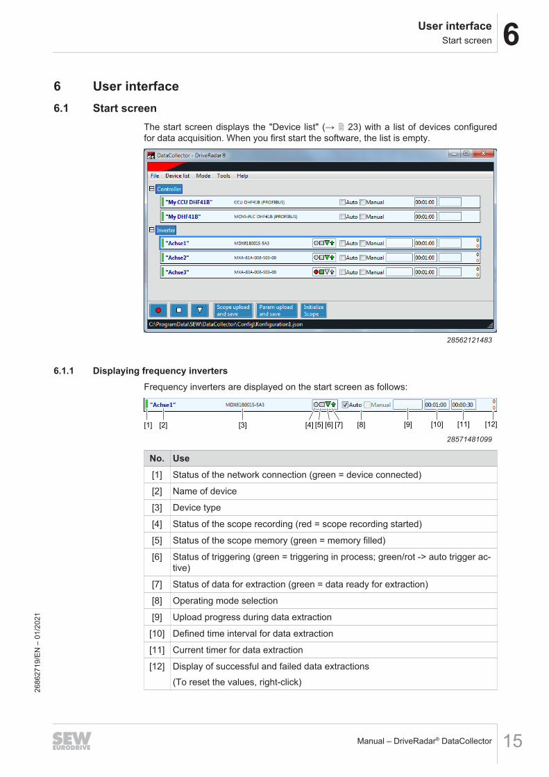
The start screen displays the "Device list" (→ 2 23) with a list of devices configuredfor data acquisition. When you first start the software, the list is empty.
28562121483
6.1.1 Displaying frequency invertersFrequency inverters are displayed on the start screen as follows:
[1] [2] [3] [4] [5] [6] [7] [8] [9] [10] [11] [12]
28571481099
No. Use[1] Status of the network connection (green = device connected)
[2] Name of device
[3] Device type
[4] Status of the scope recording (red = scope recording started)
[5] Status of the scope memory (green = memory filled)
[6] Status of triggering (green = triggering in process; green/rot -> auto trigger ac-tive)
[7] Status of data for extraction (green = data ready for extraction)
[8] Operating mode selection
[9] Upload progress during data extraction
[10] Defined time interval for data extraction
[11] Current timer for data extraction
[12] Display of successful and failed data extractions(To reset the values, right-click)
2686
2719
/EN
– 0
1/20
21
6 User interfaceConfiguration editor
Manual – DriveRadar® DataCollector16
6.1.2 Displaying controllersControllers are displayed on the start screen as follows:
[1] [2] [3] [4] [5] [6]
28571525131
No. Use[1] Status of the network connection (green = device connected)
[2] Name of device
[3] Device type
[4] Operating mode selection
[5] Defined time interval for data extraction
[6] Current timer for data extraction
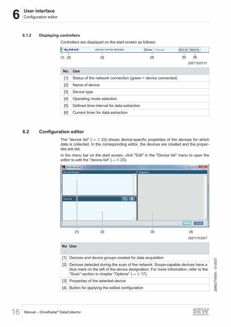
6.2 Configuration editorThe "device list" (→ 2 23) shows device-specific properties of the devices for whichdata is collected. In the corresponding editor, the devices are created and the proper-ties are set.In the menu bar on the start screen, click "Edit" in the "Device list" menu to open theeditor to edit the "device list" (→ 2 23).
[1] [2] [3] [4]
28571703307
No.
Use
[1] Devices and device groups created for data acquisition
[2] Devices detected during the scan of the network. Scope-capable devices have ablue mark on the left of the device designation. For more information, refer to the"Scan" section in chapter "Options" (→ 2 17).
[3] Properties of the selected device
[4] Button for applying the edited configuration
2686
2719
/EN
– 0
1/20
21
7SettingsLanguage
Manual – DriveRadar® DataCollector 17
7 SettingsIn the menu bar under "Settings", you will find the software settings that are describedin this chapter.
7.1 LanguageLanguage of user interface (software restart required).
7.2 Options
Dialog with the following options for software operation:
General• Open last device list
Set whether or not the last saved device list file is opened when the software isstarted.
• Folder for application descriptions
Set in which directory the lists with identifications for SEW and customer applica-tions are saved. The entries in these lists are available when configuring thedevices in the "Appl. customer" or "Appl SEW" drop-down lists. See chapter"Device configuration" (→ 2 23).Use the respective buttons below to open the lists with "SEW identification" or"Customer identification" for editing.
• Hide start screen
Specify whether to display the start screen when the program starts.
ScanSelect the network adapter used to perform a network scan. In addition, the IP ad-dress can be explicitly specified for the scan.
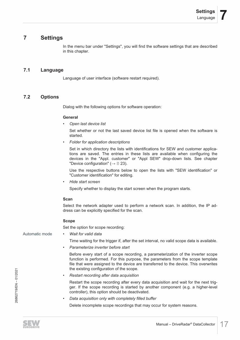
ScopeSet the option for scope recording:
Automatic mode • Wait for valid data
Time waiting for the trigger if, after the set interval, no valid scope data is available.• Parameterize inverter before start
Before every start of a scope recording, a parameterization of the inverter scopefunction is performed. For this purpose, the parameters from the scope templatefile that were assigned to the device are transferred to the device. This overwritesthe existing configuration of the scope.
• Restart recording after data acquisition
Restart the scope recording after every data acquisition and wait for the next trig-ger. If the scope recording is started by another component (e.g. a higher-levelcontroller), this option should be deactivated.
• Data acquisition only with completely filled buffer
Delete incomplete scope recordings that may occur for system reasons.
2686
2719
/EN
– 0
1/20
21
7 SettingsOptions
Manual – DriveRadar® DataCollector18
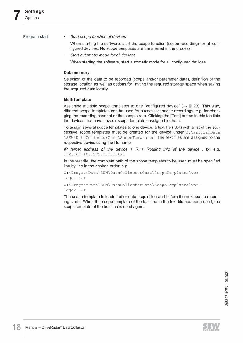
Program start • Start scope function of devices
When starting the software, start the scope function (scope recording) for all con-figured devices. No scope templates are transferred in the process.
• Start automatic mode for all devices
When starting the software, start automatic mode for all configured devices.
Data memorySelection of the data to be recorded (scope and/or parameter data), definition of thestorage location as well as options for limiting the required storage space when savingthe acquired data locally.
MultiTemplateAssigning multiple scope templates to one "configured device" (→ 2 23). This way,different scope templates can be used for successive scope recordings, e.g. for chan-ging the recording channel or the sample rate. Clicking the [Test] button in this tab liststhe devices that have several scope templates assigned to them.To assign several scope templates to one device, a text file (*.txt) with a list of the suc-cessive scope templates must be created for the device under C:\ProgramData\SEW\DataCollectorCore\ScopeTemplates. The text files are assigned to therespective device using the file name:IP target address of the device + R + Routing info of the device . txt e.g.192.168.10.12R2.1.1.1.txt
In the text file, the complete path of the scope templates to be used must be specifiedline by line in the desired order, e.g.C:\ProgramData\SEW\DataCollectorCore\ScopeTemplates\vor-lage1.SCT
C:\ProgramData\SEW\DataCollectorCore\ScopeTemplates\vor-lage2.SCT
The scope template is loaded after data acquisition and before the next scope record-ing starts. When the scope template of the last line in the text file has been used, thescope template of the first line is used again.
2686
2719
/EN
– 0
1/20
21
7SettingsMeta data
Manual – DriveRadar® DataCollector 19
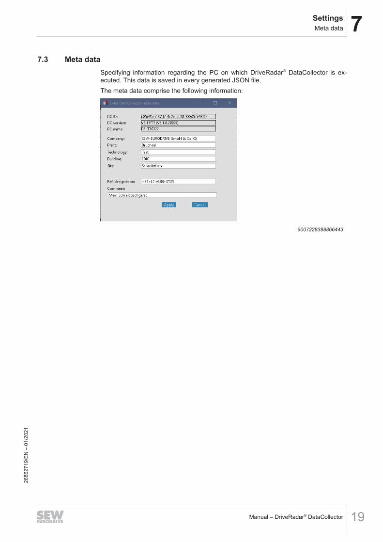
7.3 Meta dataSpecifying information regarding the PC on which DriveRadar® DataCollector is ex-ecuted. This data is saved in every generated JSON file.The meta data comprise the following information:
9007228388866443
2686
2719
/EN
– 0
1/20
21
8 StartupStartup procedure
Manual – DriveRadar® DataCollector20
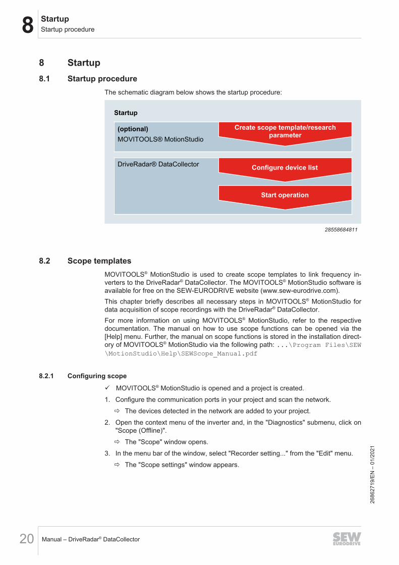
8 Startup8.1 Startup procedure
The schematic diagram below shows the startup procedure:
MOVITOOLS® MotionStudio
Create scope template/researchparameter
Startup
DriveRadar® DataCollector Configure device list
Start operation
(optional)
28558684811
8.2 Scope templatesMOVITOOLS® MotionStudio is used to create scope templates to link frequency in-verters to the DriveRadar® DataCollector. The MOVITOOLS® MotionStudio software isavailable for free on the SEW‑EURODRIVE website (www.sew‑eurodrive.com).This chapter briefly describes all necessary steps in MOVITOOLS® MotionStudio fordata acquisition of scope recordings with the DriveRadar® DataCollector.For more information on using MOVITOOLS® MotionStudio, refer to the respectivedocumentation. The manual on how to use scope functions can be opened via the[Help] menu. Further, the manual on scope functions is stored in the installation direct-ory of MOVITOOLS® MotionStudio via the following path: ...\Program Files\SEW\MotionStudio\Help\SEWScope_Manual.pdf
8.2.1 Configuring scope
ü MOVITOOLS® MotionStudio is opened and a project is created.1. Configure the communication ports in your project and scan the network.
ð The devices detected in the network are added to your project.2. Open the context menu of the inverter and, in the "Diagnostics" submenu, click on
"Scope (Offline)".ð The "Scope" window opens.
3. In the menu bar of the window, select "Recorder setting..." from the "Edit" menu.ð The "Scope settings" window appears.
2686
2719
/EN
– 0
1/20
21
8StartupScope templates
Manual – DriveRadar® DataCollector 21
[7]
[6]
[5]
[1] [2]
[3]
[4]
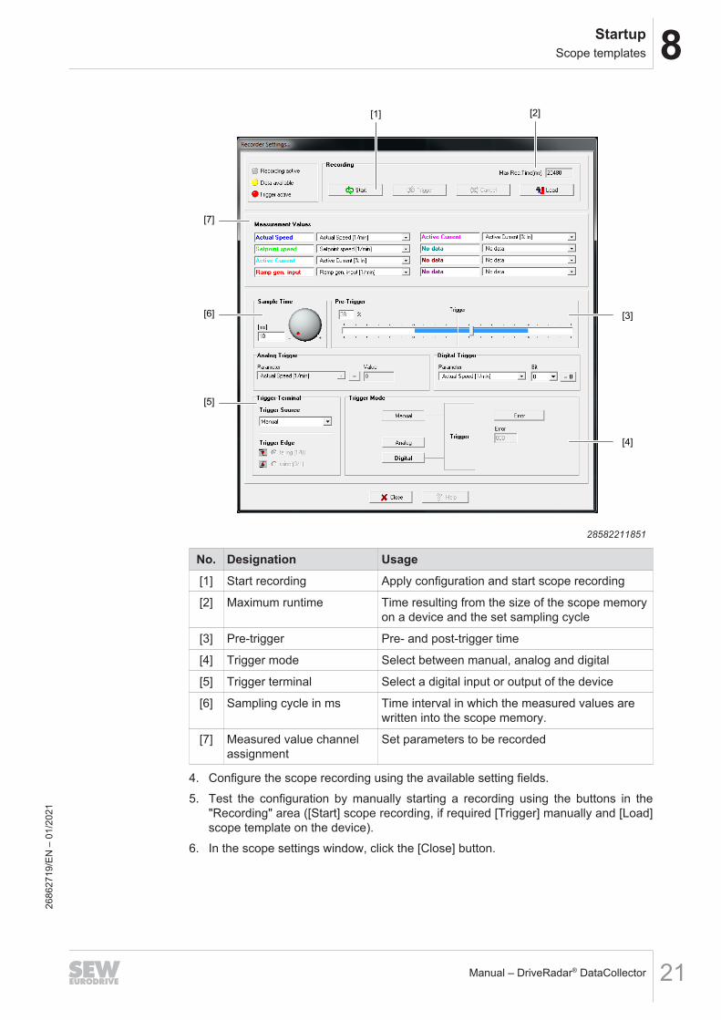
28582211851
No. Designation Usage[1] Start recording Apply configuration and start scope recording
[2] Maximum runtime Time resulting from the size of the scope memoryon a device and the set sampling cycle
[3] Pre-trigger Pre- and post-trigger time
[4] Trigger mode Select between manual, analog and digital
[5] Trigger terminal Select a digital input or output of the device
[6] Sampling cycle in ms Time interval in which the measured values arewritten into the scope memory.
[7] Measured value channelassignment
Set parameters to be recorded
4. Configure the scope recording using the available setting fields.5. Test the configuration by manually starting a recording using the buttons in the
"Recording" area ([Start] scope recording, if required [Trigger] manually and [Load]scope template on the device).
6. In the scope settings window, click the [Close] button.
2686
2719
/EN
– 0
1/20
21

8 StartupScope templates
Manual – DriveRadar® DataCollector22
8.2.2 Saving scope as templateSave the configured scope device settings as template file to link it during the configu-ration of a device in the DriveRadar® DataCollector.ü The "Scope" window of an inverter is open in MOVITOOLS® MotionStudio. See
chapter "Configuring scope" (→ 2 20).ü The scope template has been loaded to the device.1. In the "File" menu bar, click "Save as template...".2. Select a storage location and a file name for the template and click [Save].
ð The scope settings are saved as a scope template (*.sct) at the defined storagelocation.
2686
2719
/EN
– 0
1/20
21
8StartupDevice list
Manual – DriveRadar® DataCollector 23
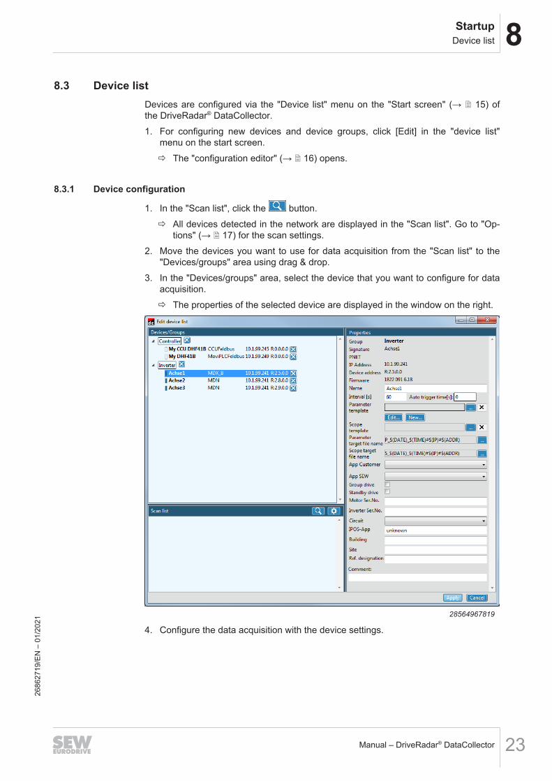
8.3 Device listDevices are configured via the "Device list" menu on the "Start screen" (→ 2 15) ofthe DriveRadar® DataCollector.1. For configuring new devices and device groups, click [Edit] in the "device list"
menu on the start screen.ð The "configuration editor" (→ 2 16) opens.
8.3.1 Device configuration
1. In the "Scan list", click the button.ð All devices detected in the network are displayed in the "Scan list". Go to "Op-
tions" (→ 2 17) for the scan settings.2. Move the devices you want to use for data acquisition from the "Scan list" to the
"Devices/groups" area using drag & drop.3. In the "Devices/groups" area, select the device that you want to configure for data
acquisition.ð The properties of the selected device are displayed in the window on the right.
28564967819
4. Configure the data acquisition with the device settings.
2686
2719
/EN
– 0
1/20
21
8 StartupDevice list
Manual – DriveRadar® DataCollector24
The following properties and settings are available for the devices:
Characteristic DescriptionGroup Group assignment of the device.
See "Grouping devices" (→ 2 28)
Signature Signature of the device
PNET PROFINET address of the device in the network
IP address IP address of the device in the network
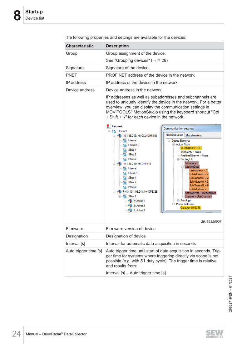
Device address Device address in the networkIP addresses as well as subaddresses and subchannels areused to uniquely identify the device in the network. For a betteroverview, you can display the communication settings inMOVITOOLS® MotionStudio using the keyboard shortcut "Ctrl+ Shift + K" for each device in the network.
29186320907
Firmware Firmware version of device
Designation Designation of device
Interval [s] Interval for automatic data acquisition in seconds
Auto trigger time [s] Auto trigger time until start of data acquisition in seconds. Trig-ger time for systems where triggering directly via scope is notpossible (e.g. with S1 duty cycle). The trigger time is relativeand results from:Interval [s] – Auto trigger time [s]
2686
2719
/EN
– 0
1/20
21
8StartupDevice list
Manual – DriveRadar® DataCollector 25
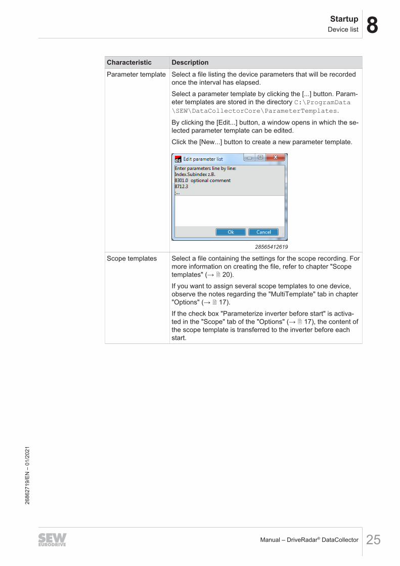
Characteristic DescriptionParameter template Select a file listing the device parameters that will be recorded
once the interval has elapsed.Select a parameter template by clicking the [...] button. Param-eter templates are stored in the directory C:\ProgramData\SEW\DataCollectorCore\ParameterTemplates.
By clicking the [Edit...] button, a window opens in which the se-lected parameter template can be edited.Click the [New...] button to create a new parameter template.
28565412619
Scope templates Select a file containing the settings for the scope recording. Formore information on creating the file, refer to chapter "Scopetemplates" (→ 2 20).If you want to assign several scope templates to one device,observe the notes regarding the "MultiTemplate" tab in chapter"Options" (→ 2 17).If the check box "Parameterize inverter before start" is activa-ted in the "Scope" tab of the "Options" (→ 2 17), the content ofthe scope template is transferred to the inverter before eachstart.
2686
2719
/EN
– 0
1/20
21

8 StartupDevice list
Manual – DriveRadar® DataCollector26
Characteristic DescriptionParameter file targetname
Name of the file in which the parameters are saved. You canset the storage location of the "Data memory" tab in the "Op-tions" (→ 2 17). You can freely select the file name. Refer tothe figure below on information on which placeholders can beused to create the file name.Tip: Use placeholders to create a file name that will allow youto assign the file to the device again later. To ensure that thenames are unique for all devices, use the placeholder$(GUID).
29186558603
Scope file targetname
Name of the file in which the scope data are saved. You canset the storage location of the "Data memory" tab in the "Op-tions" (→ 2 17). You can freely select the file name. Refer tothe figure below on information on which placeholders can beused to create the file name.Tip: Use placeholders to create a file name that will allow youto assign the file to the device again later. To ensure that thenames are unique for all devices, use the placeholder$(GUID).
29186558603
Appl. Customer Customer application to which the device is assigned (e.g. forstructuring the recorded data for evaluation). The list of applic-ations can be maintained in the "General" tab under "Op-tions" (→ 2 17).
2686
2719
/EN
– 0
1/20
21

8StartupDevice list
Manual – DriveRadar® DataCollector 27
Characteristic DescriptionAppl. SEW SEW application to which the device is assigned (e.g. for struc-
turing the recorded data for evaluation). The list of applicationscan be maintained in the "General" tab under "Op-tions" (→ 2 17).
Group drive Define the device as a group drive.
Standby drive Define the device as a standby drive.
Motor part no. Serial number of the motor.
Inverter part no. Serial number of the inverter.
Connection type Connection type of the drive.
IPOS® app Designation of the IPOS® application (is filled out automatical-ly).
Hall Hall in which the device is located.
Location Location in which the device is located.
Ref ID/OR ID Reference ID or operating resource ID of the device.
Comment Other comments.
2686
2719
/EN
– 0
1/20
21
8 StartupDevice list
Manual – DriveRadar® DataCollector28
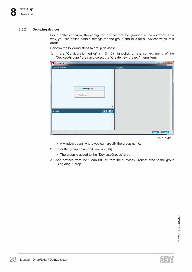
8.3.2 Grouping devicesFor a better overview, the configured devices can be grouped in the software. Thisway, you can define certain settings for one group and thus for all devices within thisgroup.Perform the following steps to group devices:1. In the "Configuration editor" (→ 2 16), right-click on the context menu of the
"Devices/Groups" area and select the "Create new group.." menu item.
28565565195
ð A window opens where you can specify the group name.2. Enter the group name and click on [OK].
ð The group is added to the "Devices/Groups" area.3. Add devices from the "Scan list" or from the "Devices/Groups" area to the group
using drag & drop.
2686
2719
/EN
– 0
1/20
21
8StartupDevice list
Manual – DriveRadar® DataCollector 29
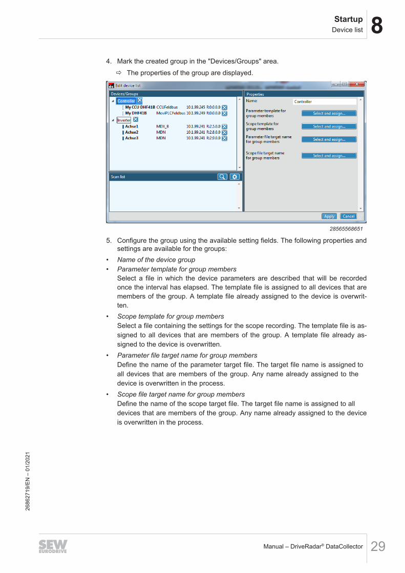
4. Mark the created group in the "Devices/Groups" area.ð The properties of the group are displayed.
28565568651
5. Configure the group using the available setting fields. The following properties andsettings are available for the groups:
• Name of the device group• Parameter template for group members
Select a file in which the device parameters are described that will be recorded once the interval has elapsed. The template file is assigned to all devices that are members of the group. A template file already assigned to the device is overwrit-ten.
• Scope template for group membersSelect a file containing the settings for the scope recording. The template file is as-signed to all devices that are members of the group. A template file already as-signed to the device is overwritten.
• Parameter file target name for group membersDefine the name of the parameter target file. The target file name is assigned to all devices that are members of the group. Any name already assigned to the device is overwritten in the process.
• Scope file target name for group membersDefine the name of the scope target file. The target file name is assigned to all devices that are members of the group. Any name already assigned to the device is overwritten in the process.
2686
2719
/EN
– 0
1/20
21
8 StartupDevice list
Manual – DriveRadar® DataCollector30
8.3.3 Saving the configuration
1. To save the configuration click "Save" or "Save as..." in the "Device list" menu ofthe menu bar on the start screen.ð With "Save", the configuration file (*.json) is saved in the directory C:\Pro-
gramData\SEW\DataCollectorCore\Config; with "Save as..." it is savedat the specified storage location.
INFORMATIONUnder "Options" (→ 2 17), you can set that the last saved configuration is alwaysloaded when starting the software.
2686
2719
/EN
– 0
1/20
21
9OperationOperating modes
Manual – DriveRadar® DataCollector 31
9 Operation9.1 Operating modes
The software has "manual mode" and "automatic mode".Manual mode is used to support startup, e.g. testing the function, configuration, orscope resolution. In this operating mode, the scope function can be initially parameter-ized manually with the configured scope template.Automatic mode is used exclusively to automatically execute the configured acquisi-tion of IIoT sensor data.
9.2 Activating manual modeProceed as follows to use manual mode:1. On the start screen, activate the "Manual" check box for all devices that you want
to control manually. If you want to activate manual mode for all devices on the startscreen, click "Activate manual mode for available devices" under "Mode" in themenu bar.ð The selected devices can be controlled manually using the buttons on the start
screen. As controllers do not have any scope function, only the button [Paramupload and save] is available for these devices.
ð The settings for saving parameter and scope data, the file names and the stor-age locations are adopted from the "Device list" (→ 2 23).
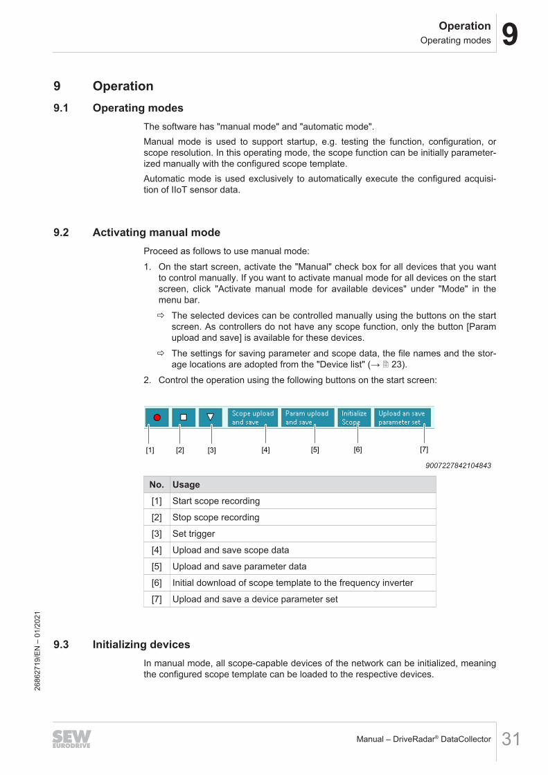
2. Control the operation using the following buttons on the start screen:
[1] [2] [3] [4] [5] [6] [7]
9007227842104843
No. Usage[1] Start scope recording
[2] Stop scope recording
[3] Set trigger
[4] Upload and save scope data
[5] Upload and save parameter data
[6] Initial download of scope template to the frequency inverter
[7] Upload and save a device parameter set
9.3 Initializing devicesIn manual mode, all scope-capable devices of the network can be initialized, meaningthe configured scope template can be loaded to the respective devices.
2686
2719
/EN
– 0
1/20
21
9 OperationStarting automatic mode
Manual – DriveRadar® DataCollector32
Proceed as follows:1. Activate "manual mode" (→ 2 31) for all devices you want to initialize.2. On the start screen click the [Initialize scope] button.
9.4 Starting automatic modeProceed as follows:1. On the start screen, deactivate the "Manual" check box for all devices that you
want to operate in automatic mode.2. Click "Start automatic mode for available devices" in the menu bar under "Mode".ð Automatic data acquisition of the devices is started.ð If the set trigger occurred, an upload of the scope memory and/or the selected pa-
rameters is realized after the set time has elapsed.ð Depending on the settings, the collected data are saved as .JSON files at the set
location.
2686
2719
/EN
– 0
1/20
21
10AppendixIIoT sensor technology properties (extract)
Manual – DriveRadar® DataCollector 33
10 Appendix
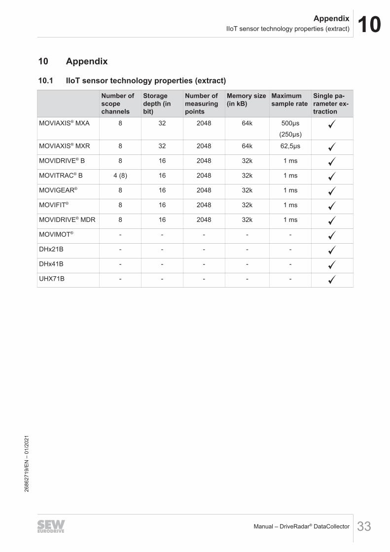
10.1 IIoT sensor technology properties (extract)
Number ofscopechannels
Storagedepth (inbit)
Number ofmeasuringpoints
Memory size(in kB)
Maximumsample rate
Single pa-rameter ex-traction
MOVIAXIS® MXA 8 32 2048 64k 500µs(250µs)
MOVIAXIS® MXR 8 32 2048 64k 62,5µs
MOVIDRIVE® B 8 16 2048 32k 1 ms
MOVITRAC® B 4 (8) 16 2048 32k 1 ms
MOVIGEAR® 8 16 2048 32k 1 ms
MOVIFIT® 8 16 2048 32k 1 ms
MOVIDRIVE® MDR 8 16 2048 32k 1 ms
MOVIMOT® - - - - -
DHx21B - - - - -
DHx41B - - - - -
UHX71B - - - - -
2686
2719
/EN
– 0
1/20
21
10 AppendixSample topologies
Manual – DriveRadar® DataCollector34
10.2 Sample topologies
INFORMATIONDo not execute MOVITOOLS® MotionStudio and DriveRadar® DataCollector for onedevice at the same time as that may impair the functionalities.
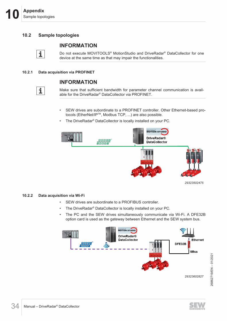
10.2.1 Data acquisition via PROFINET
INFORMATIONMake sure that sufficient bandwidth for parameter channel communication is avail-able for the DriveRadar® DataCollector via PROFINET.
• SEW drives are subordinate to a PROFINET controller. Other Ethernet-based pro-tocols (EtherNet/IPTM, Modbus TCP, ...) are also possible.
• The DriveRadar® DataCollector is locally installed on your PC.
29323502475
10.2.2 Data acquisition via Wi-Fi• SEW drives are subordinate to a PROFIBUS controller.• The DriveRadar® DataCollector is locally installed on your PC.• The PC and the SEW drives simultaneously communicate via Wi-Fi. A DFE32B
option card is used as the gateway between Ethernet and the SEW system bus.
29323602827
2686
2719
/EN
– 0
1/20
21
10AppendixSample topologies
Manual – DriveRadar® DataCollector 35
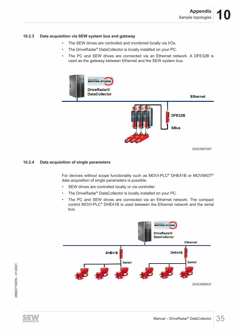
10.2.3 Data acquisition via SEW system bus and gateway• The SEW drives are controlled and monitored locally via I/Os.• The DriveRadar® DataCollector is locally installed on your PC.• The PC and SEW drives are connected via an Ethernet network. A DFE32B is
used as the gateway between Ethernet and the SEW system bus.
29323597067
10.2.4 Data acquisition of single parameters
For devices without scope functionality such as MOVI-PLC® DHE41B or MOVIMOT®
data acquisition of single parameters is possible.• SEW drives are controlled locally or via controller.• The DriveRadar® DataCollector is locally installed on your PC.• The PC and SEW drives are connected via an Ethernet network. The compact
control MOVI-PLC® DHE41B is used between the Ethernet network and the serialbus.
29323499531
2686
2719
/EN
– 0
1/20
21
Index
IndexA
Appendix ............................................................. 33
C
Copyright notice .................................................... 7
D
Decimal separator ................................................. 7
E
Embedded safety notes......................................... 6EtherCAT®
Beckhoff trademark .......................................... 7
H
Hazard symbolsMeaning............................................................ 6
N
NotesDesignation in the documentation .................... 6Meaning of the hazard symbols ....................... 6
P
Product names ...................................................... 7Project planning................................................... 11
R
Rights to claim under limited warranty .................. 7
S
Safety notesBus systems ..................................................... 8Designation in the documentation .................... 6Meaning of the hazard symbols ....................... 6Preliminary information..................................... 8Structure of embedded..................................... 6Structure of section-related .............................. 6
Section-related safety notes.................................. 6Signal words in safety notes.................................. 6
T
Target group.......................................................... 8Trademarks ........................................................... 7
U
Use, designated .................................................... 8
2686
2719
/EN
– 0
1/21
Manual – DriveRadar® DataCollector36


SEW-EURODRIVE—Driving the world
SEW-EURODRIVE GmbH & Co KGErnst-Blickle-Str. 4276646 BRUCHSALGERMANYTel. +49 7251 75-0Fax +49 7251 [email protected]
Related Documents