Proceedings of the International Conference on Industrial Engineering and Operations Management Washington DC, USA, September 27-29, 2018 © IEOM Society International Driver Awareness System Using RFID Technology: A collaboration in Senior Design Projects Emad Abd-Elrady Abu Dhabi Women’s College, Higher Colleges of Technology P.O. Box 41012 Abu Dhabi, UAE. [email protected] Osama Abuelkheir Atlas Telecom AD Abu Dhabi, UAE. [email protected] Said Kafumbe Abu Dhabi Women’s College, Higher Colleges of Technology P.O. Box 41012 Abu Dhabi, UAE. [email protected] Abstract Road traffic safety refers to the methods and measures used to prevent road users from being killed or seriously injured. Typical road users include: pedestrians and vehicle passengers. A collaboration work with a Telecommunication industrial partner in senior design graduation projects considers enhancing road safety. In this work, Radio Frequency Identification (RFID) technology is used in order to develop driver awareness systems against pedestrian crossing, foggy weather collisions, construction road site, and bridge crash. This paper will focus on the awareness system developed against pedestrian crossing. Keywords Arduino microcontroller; awareness systems; RFID technology; road safety. 1. Introduction Road traffic safety is an important worldwide topic [1] and road injuries are one of the leading causes of death for children. Two out of every three fatally injured children die due to road traffic crashes. Many studies considered using Radio Frequency Identification (RFID) technology [2-5] in order to achieve more safe roads and hence reducing number of accidents [6-9]. RFID refers to a technology whereby digital data encoded in RFID smart label or tag - that consists of an integrated circuit and an antenna - are captured by a reader via radio waves. RFID is similar to barcoding in that data from a tag are captured by a device that stores the data in a database. RFID, however, has several advantages over barcode systems. The RFID tag data can be read outside the line-of-sight, whereas barcodes must be aligned with an optical scanner. Also, RFID tags are read/write, i.e. the data on the tag can be rewritten or modified as needed but it is read only in barcodes. Even data on RFID tags can be encrypted. Moreover, RFID tags are more durable and reusable than barcodes. In senior design graduation projects, different driver awareness techniques were practically implemented and tested in different road hazard conditions. Three awareness systems has been developed. Namely: driver 299

Welcome message from author
This document is posted to help you gain knowledge. Please leave a comment to let me know what you think about it! Share it to your friends and learn new things together.
Transcript

Proceedings of the International Conference on Industrial Engineering and Operations Management
Washington DC, USA, September 27-29, 2018
© IEOM Society International
Driver Awareness System Using RFID Technology:
A collaboration in Senior Design Projects
Emad Abd-Elrady
Abu Dhabi Women’s College, Higher Colleges of Technology
P.O. Box 41012 Abu Dhabi, UAE.
Osama Abuelkheir
Atlas Telecom AD
Abu Dhabi, UAE.
Said Kafumbe
Abu Dhabi Women’s College, Higher Colleges of Technology
P.O. Box 41012 Abu Dhabi, UAE.
Abstract
Road traffic safety refers to the methods and measures used to prevent road users from being killed or
seriously injured. Typical road users include: pedestrians and vehicle passengers. A collaboration work
with a Telecommunication industrial partner in senior design graduation projects considers enhancing road
safety. In this work, Radio Frequency Identification (RFID) technology is used in order to develop driver
awareness systems against pedestrian crossing, foggy weather collisions, construction road site, and bridge
crash. This paper will focus on the awareness system developed against pedestrian crossing.
Keywords
Arduino microcontroller; awareness systems; RFID technology; road safety.
1. Introduction
Road traffic safety is an important worldwide topic [1] and road injuries are one of the leading causes of
death for children. Two out of every three fatally injured children die due to road traffic crashes. Many
studies considered using Radio Frequency Identification (RFID) technology [2-5] in order to achieve more
safe roads and hence reducing number of accidents [6-9].
RFID refers to a technology whereby digital data encoded in RFID smart label or tag - that consists of an
integrated circuit and an antenna - are captured by a reader via radio waves. RFID is similar to barcoding
in that data from a tag are captured by a device that stores the data in a database. RFID, however, has several
advantages over barcode systems. The RFID tag data can be read outside the line-of-sight, whereas barcodes
must be aligned with an optical scanner. Also, RFID tags are read/write, i.e. the data on the tag can be
rewritten or modified as needed but it is read only in barcodes. Even data on RFID tags can be encrypted.
Moreover, RFID tags are more durable and reusable than barcodes.
In senior design graduation projects, different driver awareness techniques were practically implemented
and tested in different road hazard conditions. Three awareness systems has been developed. Namely: driver
299
Proceedings of the International Conference on Industrial Engineering and Operations Management
Washington DC, USA, September 27-29, 2018
© IEOM Society International
awareness system against pedestrian crossing, driver awareness system against foggy weather collisions,
and driver awareness system for construction road site, and bridge crash. This paper focuses on the
pedestrian awareness project.
The safety of pedestrians is a very important issue nowadays. Traffic police have already taken numerous
steps to ensure the safety of pedestrians and are still taking vital steps forward. The most important issue in
this regard is that Pedestrians, especially children and special needs people may not know about an
approaching vehicle. This project has been designed to make sure that the pedestrians present on the streets
can cross the road safely. For this purpose, this project proposes installation of a broadcaster for traffic
movement and monitoring through RFID. In order to implement such a system, the real challenge would
be to measure the speed of a vehicle and the movement of pedestrians accordingly. This would have to be
done within seconds before a flash message is displayed to warn both the pedestrian and the driver.
In Section 2, the system description is presented. The block diagrams of the project subsystems are
introduced in Section 3. In Section 4, the wiring of different subsystems is shown. Arduino programing
flow charts are given in Section 5. In section 6, system testing of different subsystems is shown. Results
and discussion are presented in Section 7. Conclusions are given in Section 8.
2. Methodology
2.1 Block Diagrams
The proposed project to detect the vehicle as well as the child using RFID reader includes the following
five main Subsystems:
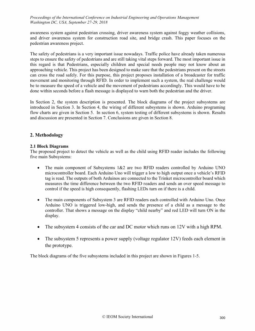
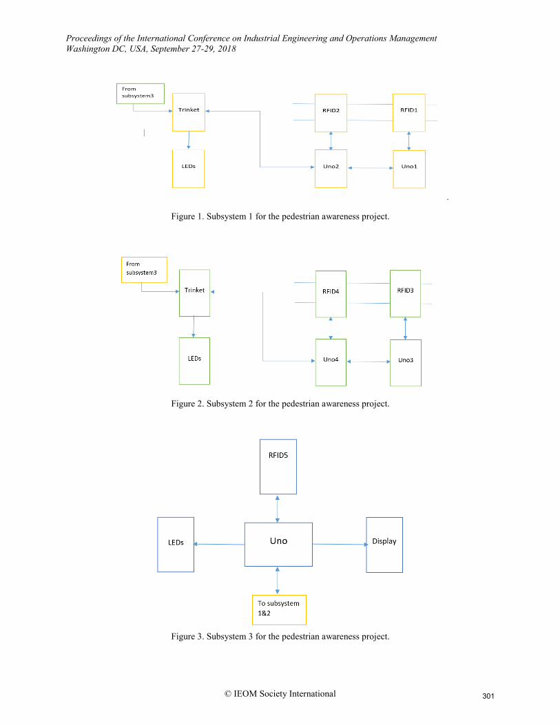
The main component of Subsystems 1&2 are two RFID readers controlled by Arduino UNO
microcontroller board. Each Arduino Uno will trigger a low to high output once a vehicle’s RFID
tag is read. The outputs of both Arduinos are connected to the Trinket microcontroller board which
measures the time difference between the two RFID readers and sends an over speed message to
control if the speed is high consequently, flashing LEDs turn on if there is a child.
The main components of Subsystem 3 are RFID readers each controlled with Arduino Uno. Once
Arduino UNO is triggered low-high, and sends the presence of a child as a message to the
controller. That shows a message on the display “child nearby” and red LED will turn ON in the
display.
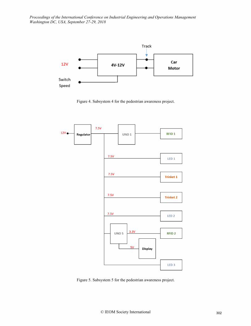
The subsystem 4 consists of the car and DC motor which runs on 12V with a high RPM.
The subsystem 5 represents a power supply (voltage regulator 12V) feeds each element in
the prototype.
The block diagrams of the five subsystems included in this project are shown in Figures 1-5.
300
Proceedings of the International Conference on Industrial Engineering and Operations Management
Washington DC, USA, September 27-29, 2018
© IEOM Society International
Figure 1. Subsystem 1 for the pedestrian awareness project.
Figure 2. Subsystem 2 for the pedestrian awareness project.
Figure 3. Subsystem 3 for the pedestrian awareness project.
301
Proceedings of the International Conference on Industrial Engineering and Operations Management
Washington DC, USA, September 27-29, 2018
© IEOM Society International
Figure 4. Subsystem 4 for the pedestrian awareness project.
Figure 5. Subsystem 5 for the pedestrian awareness project.
302
Proceedings of the International Conference on Industrial Engineering and Operations Management
Washington DC, USA, September 27-29, 2018
© IEOM Society International
2.2 Programming Flow Charts
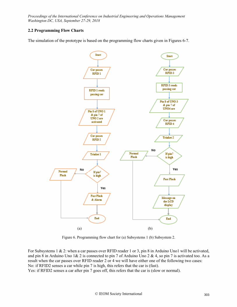
The simulation of the prototype is based on the programming flow charts given in Figures 6-7.
(a) (b)
Figure 6. Programming flow chart for (a) Subsystems 1 (b) Subsystem 2.
For Subsystems 1 & 2: when a car passes over RFID reader 1 or 3, pin 8 in Arduino Uno1 will be activated,
and pin 8 in Arduino Uno 1& 2 is connected to pin 7 of Arduino Uno 2 & 4, so pin 7 is activated too. As a
result when the car passes over RFID reader 2 or 4 we will have either one of the following two cases:
No: if RFID2 senses a car while pin 7 is high, this refers that the car is (fast).
Yes: if RFID2 senses a car after pin 7 goes off, this refers that the car is (slow or normal).
303
Proceedings of the International Conference on Industrial Engineering and Operations Management
Washington DC, USA, September 27-29, 2018
© IEOM Society International
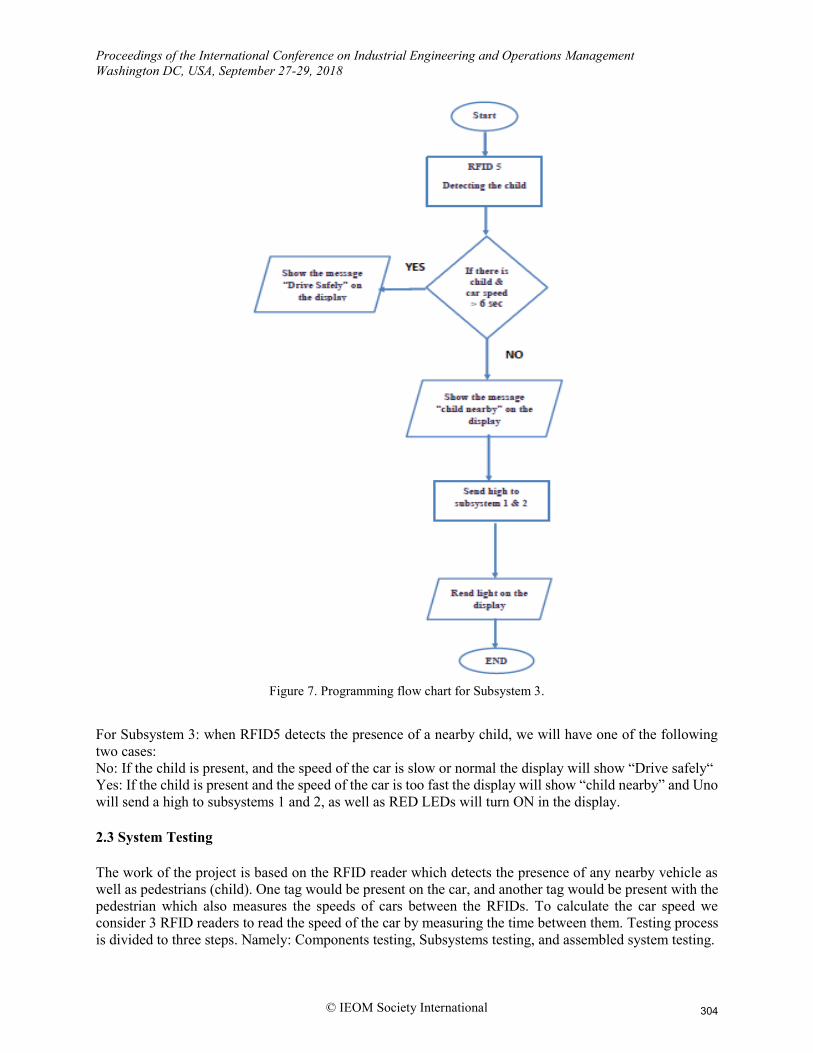
Figure 7. Programming flow chart for Subsystem 3.
For Subsystem 3: when RFID5 detects the presence of a nearby child, we will have one of the following
two cases:
No: If the child is present, and the speed of the car is slow or normal the display will show “Drive safely“
Yes: If the child is present and the speed of the car is too fast the display will show “child nearby” and Uno
will send a high to subsystems 1 and 2, as well as RED LEDs will turn ON in the display.
2.3 System Testing
The work of the project is based on the RFID reader which detects the presence of any nearby vehicle as
well as pedestrians (child). One tag would be present on the car, and another tag would be present with the
pedestrian which also measures the speeds of cars between the RFIDs. To calculate the car speed we
consider 3 RFID readers to read the speed of the car by measuring the time between them. Testing process
is divided to three steps. Namely: Components testing, Subsystems testing, and assembled system testing.
304
Proceedings of the International Conference on Industrial Engineering and Operations Management
Washington DC, USA, September 27-29, 2018
© IEOM Society International
a) Component Testing
The initial test done for each component is to check their activation and operation. Then building and testing
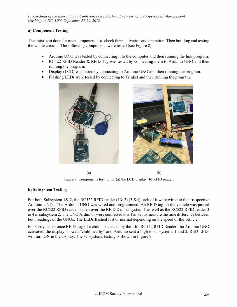
the whole circuits. The following components were tested (see Figure 8):
Arduino UNO was tested by connecting it to the computer and then running the link program.
RC522 RFID Reader & RFID Tag was tested by connecting them to Arduino UNO and then
running the program.
Display (LCD) was tested by connecting to Arduino UNO and then running the program.
Flashing LEDs were tested by connecting to Trinket and then running the program.
(a) (b)
Figure 8. Components testing for (a) the LCD display (b) RFID reader.
b) Subsystem Testing
For both Subsystem 1& 2, the RC522 RFID reader (1& 2) (3 &4) each of it were wired to their respective
Arduino UNOs. The Arduino UNO was wired and programmed. An RFID tag on the vehicle was passed
over the RC522 RFID reader 1 then over the RFID 2 in subsystem 1 as well as the RC522 RFID reader 3
& 4 in subsystem 2, The UNO Arduinos were connected to a Trinket to measure the time difference between
both readings of the UNOs. The LEDs flashed fast or normal depending on the speed of the vehicle.
For subsystem 3 once RFID Tag of a child is detected by the fifth RC522 RFID Reader, the Arduino UNO
activated, the display showed “child nearby” and Arduino sent a high to subsystems 1 and 2, RED LEDs
will turn ON in the display. The subsystems testing is shown in Figure 9.
305

Proceedings of the International Conference on Industrial Engineering and Operations Management
Washington DC, USA, September 27-29, 2018
© IEOM Society International
(a) (b)
(c) (d)
Figure 9. Testing for (a) Subsystems 1 & 2 (b) Subsystem 3 (c) Subsystem 4 (d) Subsystem 5.
c) Assembled System Testing
The system assembly was started after the subsystems were tested to ensure it operates in a stable way. The
project members were able to compile the parts of the prototype and the program was working successfully.
However, some errors appeared during the first final test and were corrected by the team. The errors will
be explained in the results. The project members worked on the approach to have both Arduinos and the
Trinket works in sequence with the RFID readers.
3. Results and Discussion
Once all the components were tested, the team was able to identify any required enhancements or
modifications to the components and plans. The first challenge was with the flashing LEDs on the side of
the track, they must flash faster when there is a pedestrian and a car moving at high speed. However, it was
flashing faster before the car reached the RFID reader 2, so the project team identified that the coded time
was a little bit high. As a result, the coded time was modified and changed from 6sec to 4 sec.
306

Proceedings of the International Conference on Industrial Engineering and Operations Management
Washington DC, USA, September 27-29, 2018
© IEOM Society International
In order to calculate the car speed we consider 3 RFID reader to read the speed of the car by measuring the
time between them. For instance, we considered the time 5 sec, if the car is moving and reaching to the next
RFID reader in less than 5 sec, it means that the car is moving very fast. However, if it is reaching to the
next RFID reader in more than 5sec, it means the car is moving slowly.
The car speed was controlled by varying the voltage applied to the car track from 9V to 12V to simulate
high speed. Another challenge was that the motor of the used car had a low torque and high speed with
15000 rpm. In order to control the speed of the car and guarantee that the car is moving in a stable way, the
solution was modifying the hardware to have high torque and lower speed with 12000rpm at 12 V.
In some cases, the car was moving out of the track, so the project team increased the weight of the car in
order to improve the contact of the car with the track, and we added a magnet under the car to hold the car
on the track. Moreover, the distance between two RFIDs are very short as a result difficult to calculate the
time also distinguishing between high speed and low speed was not possible in order to reduce the time to
milliseconds. Also, the relay on the LED and LCD output display was very sensitive which caused the
messages shown on the display to be unstable and/or missing so it was replaced with a transistor buffer.
One of the Trinkets wasn’t reliable and unstable so it was replaced with Arduino YUN.
Considering the RFID reader of the pedestrian as a first input, and the RFID reader of an existing car on
the road as a second input:
If a child is present and the car passes between Subsystems 1& 2 in a normal or slow speed the
LEDs will flash slowly and the red LEDs in Subsystem 5 will turn ON as well as the display will
show a message “Drive Safely “.
If a child is present and the car passes between Subsystems 1& 2 in a high speed (over speed) the
LEDs will flash faster and the red LEDs in Subsystem 5 will turn ON as well as the display will
show a message “A Child is Nearby “.
If a car passes between Subsystems 1& 2 in a high speed and if there is no child the LEDs will not
be flashing and the green LEDs in Subsystem 5 will be turned ON.
If there is no child (0) and there is a car (1) it will not show anything.
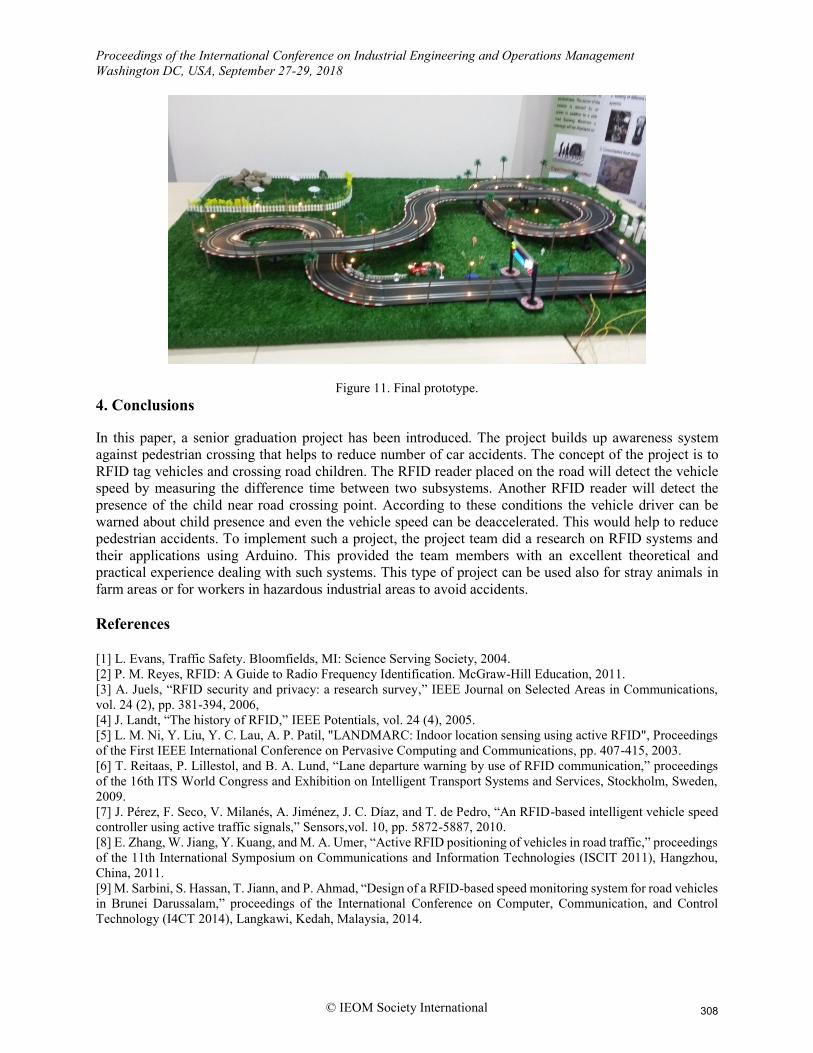
Figure 10 shows the flash light, LEDs and the LCD screen in operation. The complete prototype of the
project is shown in Figure 11.
Figure 10. Flash light, LEDs and LCD screen in operation.
307
Proceedings of the International Conference on Industrial Engineering and Operations Management
Washington DC, USA, September 27-29, 2018
© IEOM Society International
Figure 11. Final prototype.
4. Conclusions
In this paper, a senior graduation project has been introduced. The project builds up awareness system
against pedestrian crossing that helps to reduce number of car accidents. The concept of the project is to
RFID tag vehicles and crossing road children. The RFID reader placed on the road will detect the vehicle
speed by measuring the difference time between two subsystems. Another RFID reader will detect the
presence of the child near road crossing point. According to these conditions the vehicle driver can be
warned about child presence and even the vehicle speed can be deaccelerated. This would help to reduce
pedestrian accidents. To implement such a project, the project team did a research on RFID systems and
their applications using Arduino. This provided the team members with an excellent theoretical and
practical experience dealing with such systems. This type of project can be used also for stray animals in
farm areas or for workers in hazardous industrial areas to avoid accidents.
References
[1] L. Evans, Traffic Safety. Bloomfields, MI: Science Serving Society, 2004.
[2] P. M. Reyes, RFID: A Guide to Radio Frequency Identification. McGraw-Hill Education, 2011.
[3] A. Juels, “RFID security and privacy: a research survey,” IEEE Journal on Selected Areas in Communications,
vol. 24 (2), pp. 381-394, 2006,
[4] J. Landt, “The history of RFID,” IEEE Potentials, vol. 24 (4), 2005.
[5] L. M. Ni, Y. Liu, Y. C. Lau, A. P. Patil, "LANDMARC: Indoor location sensing using active RFID", Proceedings
of the First IEEE International Conference on Pervasive Computing and Communications, pp. 407-415, 2003.
[6] T. Reitaas, P. Lillestol, and B. A. Lund, “Lane departure warning by use of RFID communication,” proceedings
of the 16th ITS World Congress and Exhibition on Intelligent Transport Systems and Services, Stockholm, Sweden,
2009.
[7] J. Pérez, F. Seco, V. Milanés, A. Jiménez, J. C. Díaz, and T. de Pedro, “An RFID-based intelligent vehicle speed
controller using active traffic signals,” Sensors,vol. 10, pp. 5872-5887, 2010.
[8] E. Zhang, W. Jiang, Y. Kuang, and M. A. Umer, “Active RFID positioning of vehicles in road traffic,” proceedings
of the 11th International Symposium on Communications and Information Technologies (ISCIT 2011), Hangzhou,
China, 2011.
[9] M. Sarbini, S. Hassan, T. Jiann, and P. Ahmad, “Design of a RFID-based speed monitoring system for road vehicles
in Brunei Darussalam,” proceedings of the International Conference on Computer, Communication, and Control
Technology (I4CT 2014), Langkawi, Kedah, Malaysia, 2014.
308
Related Documents